embedded systems 1: hardware description languages...
TRANSCRIPT

Embedded Systems 1: Hardware Description Languages (HDLs) for Design
Davide Zoni PhDemail: [email protected]
webpage: home.deib.polimi.it/zoni
November 2017
2
Embedded Systems 1 Davide Zoni
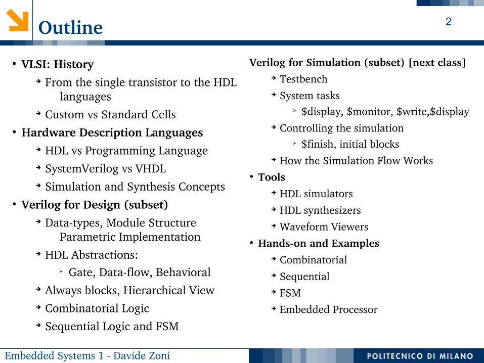
Outline
Verilog for Simulation (subset) [next class]➔ Testbench➔ System tasks
➢ $display, $monitor, $write,$display➔ Controlling the simulation
➢ $finish, initial blocks➔ How the Simulation Flow Works
● Tools➔ HDL simulators➔ HDL synthesizers➔ Waveform Viewers
● Handson and Examples➔ Combinatorial➔ Sequential➔ FSM➔ Embedded Processor
● VLSI: History➔ From the single transistor to the HDL
languages➔ Custom vs Standard Cells
● Hardware Description Languages➔ HDL vs Programming Language➔ SystemVerilog vs VHDL➔ Simulation and Synthesis Concepts
● Verilog for Design (subset)➔ Datatypes, Module Structure
Parametric Implementation➔ HDL Abstractions:
➢ Gate, Dataflow, Behavioral➔ Always blocks, Hierarchical View➔ Combinatorial Logic➔ Sequential Logic and FSM

3
Embedded Systems 1 Davide Zoni
Reference Books
● “Verilog HDL: A Guide to Digital Design and Synthesis”, 2nd Ed., Samir Palnitkar, 2003, Prentice Hall PTR
● “Fundamentals of Digital Logic with Verilog Design”, 3rd Edition, Stephen Brown and Zvonko Vranesic
● “FPGA prototyping by Verilog examples: Xilinx Spartan3 Version”, Pong P. Chu, 2008, Wiley

4
Embedded Systems 1 Davide Zoni
The VLSI Evolution
Very Large Scale Integrated (VLSI) Circuits● Late 1970s: the process of creating an integrated
circuit made of thousands of transistors into a single chip.
● The Moore’s Law predict a double in the chip transistor count every 18months
➔ Nowadays almost any reasonable complex digital design follows in the VLSI category
Technology Libraries● Full Custom Cells
➔ Huge effort to design the adhoc cells for each design
● SemiCustom Cells● Standard Cells
➔ Design the technology library once, then move the optimization effort to the circuit design stage up to the place&route
● INTegrated Electronics (Intel)➔ 1968: founded by Moore and Noyce with a focus on memory chips➔ 1971: Intel 4004, 4bit datapath @ 108KHz. 2300 transistors @ 10um➔ 1972: Intel 8008, 8bit datapath. 3500 transistors➔ 1974: intel 8080, 2MHz 6000 transistors @ 6um➔ …

5
Embedded Systems 1 Davide Zoni
The need for a better HW description methodology
CURRENT STATUS:
The increase in the transistor count in the same chip allows for:● More functionalities ● More complex functions
ISSUES:● The gate level design optimization
(handmade) is not practical anymore● (Possibly) design a custom cell for each
gate of the design is not viable anymore
NEW REQUIREMENTS:● A flexible, scalable and maintainable way to
describe the hardware, also easing the optimization design stage
● Possibly a testing and verification language support can be a [huge] advantage
SINGLE FUNCTION DESIGN
MULTIPLE FUNCTIONS WITHIN THE SAME DESIGN
And
And
Not
DFF
And
And
Not
DFF
And
And
Not
DFF
And
And
Not
DFF
And
And
Not
DFF

6
Embedded Systems 1 Davide Zoni
SystemVerilog: Dawn and Evolution
● SystemVerilog is a hardware description (and verification) language➔ Actually it is more than this, while we focus on a subset of the entire specification.
➢ Keep an eye on the complexity➢ We explore the widely used parts, that allows the design up to a complete SoC
● The History of Verilog:➔ 1983: Gateway Design Automation invented Verilog➔ 1990: Cadence bought Verilog. Transferred into the public domain and became a standard IEEE STD. 13641995
aka Verilog95➔ Later versions:
➢ Verilog 2001 (what we are considering in the rest of these classes)➢ SystemVerilog/Verilog 2005, SystemVerilog 2008, SystemVerilog 2012
● VHDL (VHSIC Hardware Description Language)➔ Published in 1987 with Dept. of Defence support as IEEE STD. 10761987➔ Later Versions: 1987,1993, 2000, 2002, 2008
● Verilog and VHDL share the same HDL opportunities➔ Verilog is Clike➔ VHDL is Adalike
WHY HDLs ? Hardware description language (HDL) is a deviceindependent representation of digital logic

7
Embedded Systems 1 Davide Zoni
Final Goals of These Classes
● Presenting the HDL basics to:➔ read and design simple combinatorial/sequential circuits and FSMs➔ Behavioral simulation of the design, only (post synthesis sim during ES1 projects)➔ From the specification to an HDL of the required design
● We are constrained to a subset of the SystemVerilog language➔ Reduce the complexity to start approaching HDLs (subset of Verilog 2001)➔ The focus is the parts that are really useful for real designs➔ This is not an HDL course
● A subset of the Verilog 2001 language is used
➔ SystemVerilog and Verilog are used in the rest of this talk interchangeably with the clear meaning of Verilog 2001 subset
➔ This is not limiting you in the offered functionalities, while the notation could be a little more verbose
8
Embedded Systems 1 Davide Zoni
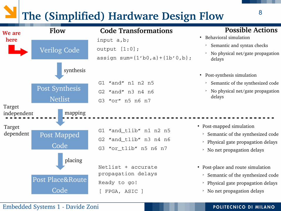
The (Simplified) Hardware Design Flow
input a,b;
output [1:0];
assign sum={1’b0,a}+{1b’0,b};Verilog Code
Post Synthesis
Netlist
Post Mapped
Code
Post Place&Route
Code
Target independent
Target dependent
G1 “and” n1 n2 n5
G2 “and” n3 n4 n6
G3 “or” n5 n6 n7
Possible ActionsCode Transformations● Behavioral simulation
➢ Semantic and syntax checks➢ No physical net/gate propagation
delays
● Postsynthesis simulation➢ Semantic of the synthesized code➢ No physical net/gate propagation
delays
Flow
● Postmapped simulation➢ Semantic of the synthesized code➢ Physical gate propagation delays➢ No net propagation delays
G1 “and_tlib” n1 n2 n5
G2 “and_tlib” n3 n4 n6
G3 “or_tlib” n5 n6 n7
Netlist + accurate propagation delays
Ready to go!
[ FPGA, ASIC ]
● Postplace and route simulation➢ Semantic of the synthesized code➢ Physical gate propagation delays➢ No net propagation delays
We are here
synthesis
mapping
placing

9
Embedded Systems 1 Davide Zoni
Verilog 2001: The Basic “Ingredients”

10
Embedded Systems 1 Davide Zoni
Verilog 2001: Data Types
● Vector of bits is the only data type we consider in these classes➔ No struct or float➔ Integer is a 32bit vector➔ String can be declared as an nbit vector where each char is 8bit long
● Each bit of the vector can take on one of four values
Value Meaning Simulation
Meaning Synthesis
0 Logic zero Logic zero
1 Logic one Logic one
X Unknown Don’t care
Z High impedance
High Impedance
● Set X in simulation where we want don’t care, thus helping the synthesis results.
● Moreover, it helps finding bugs

11
Embedded Systems 1 Davide Zoni
Verilog 2001: How to Represent the Information
● Binary literals➔ 8’b0000_0000➔ 8’b0xx0_1xx1
● Hexadecimal literals➔ 32’h0123_cdef➔ 16’haxxx
● Decimal literals➔ 32’d58
8’b0101_1111
Decimal number representing the size in bits
Base format
( d – decimal
b – binary
o – octat
h – hexadecimal )
Underscores are ignored
Bit literals

12
Embedded Systems 1 Davide Zoni
Verilog 2001: wire and reg
● wire: ➔ used to denote a hardware net
➢ wire [15:0] instruction;➢ Wire [7:0] byte_bus;
● reg: ➔ It is a variable that can be used to implement both
combinatorial and sequential logic➔ It does not identify a hardware register
● NOTE:➔ Verilog provides no type safety at all by connecting nets or regs.➔ Verilog only checks the width of the two connecting signals

13
Embedded Systems 1 Davide Zoni
Verilog 2001: Boolean Operators
● Bitwise operators: perform bitsliced operations on vectors➔ ~(4’b1010)={~1,~0,~1,~0}=4’b0101➔ 4’b1010 & 4’b0011 = 4’b0010
● Logical operators: return onebit result➔ a && b
● Reduction operators: ➔ bitwise operation on a single operand returning onebit result➔ &(4’b0101) = 0 & 1 & 0 & 1 =1’b0
● Comparison: boolean test on two arguments
~a NOT
a & b AND
a | b OR
a ^ b XOR
a~^b XNOR
&a AND
~&a NAND
|a OR
~| NOR
^ XOR
!a NOT
a && b AND
a || b OR
a<b a>b a>=b
Relational
a==b a!=b
(in)equality. Returns x when x or z in bits. Else 0 or 1, bitwise comparison
a === b a !== b
Case (in)equality. Returns 0 or 1on a bitBYbit
comparison. x and z values matter
Bitwise LogicalReduction
Comparison

14
Embedded Systems 1 Davide Zoni
Verilog 2001: The Module
● Modules are the basic building blocks in Verilog➔ Hardware blocks: made of synthesizable Verilog code➔ Testing blocks: made of nonsynthesizable Verilog code
● Verilog designs consist of interconnected modules➔ A module can instantiate other modules as children
● NOTE: split between synthesizable VS nonsynthesizable code➔ System tasks, delays using # char, tasks are not synthesizable➔ Several coding styles are not synthesizable: e.g. loops with a nonconstant loop
variable
module dut(in1,in2...,out1,out2...);
input in1;
input in2;
output out;
<impl of the module>
endmodule
The module’s behavior can be described in many different ways, but it should not matter from outside

15
Embedded Systems 1 Davide Zoni
Verilog 2001: How to Describe the
Semantic of the Module

16
Embedded Systems 1 Davide Zoni
HDL: module body description
● High level description of a module semantic using all the features of the language: combination of always blocks and continuous assignments
● When:➔ Nonsynthesizable logic or complex module
hierarchy➔ Let the synthesizer the maximum optimization
opportunities
Behavioral
Data-Flow
Gate-Level
● Continuous assignments, only. Description follows the data flow
● When:➔ Is there a clear data flow structure to follow?
● Use the basic gates only to describe the semantic of a module. No behavioral level constructs allowed
● When:➔ Constraint to a specific implementation
17
Embedded Systems 1 Davide Zoni
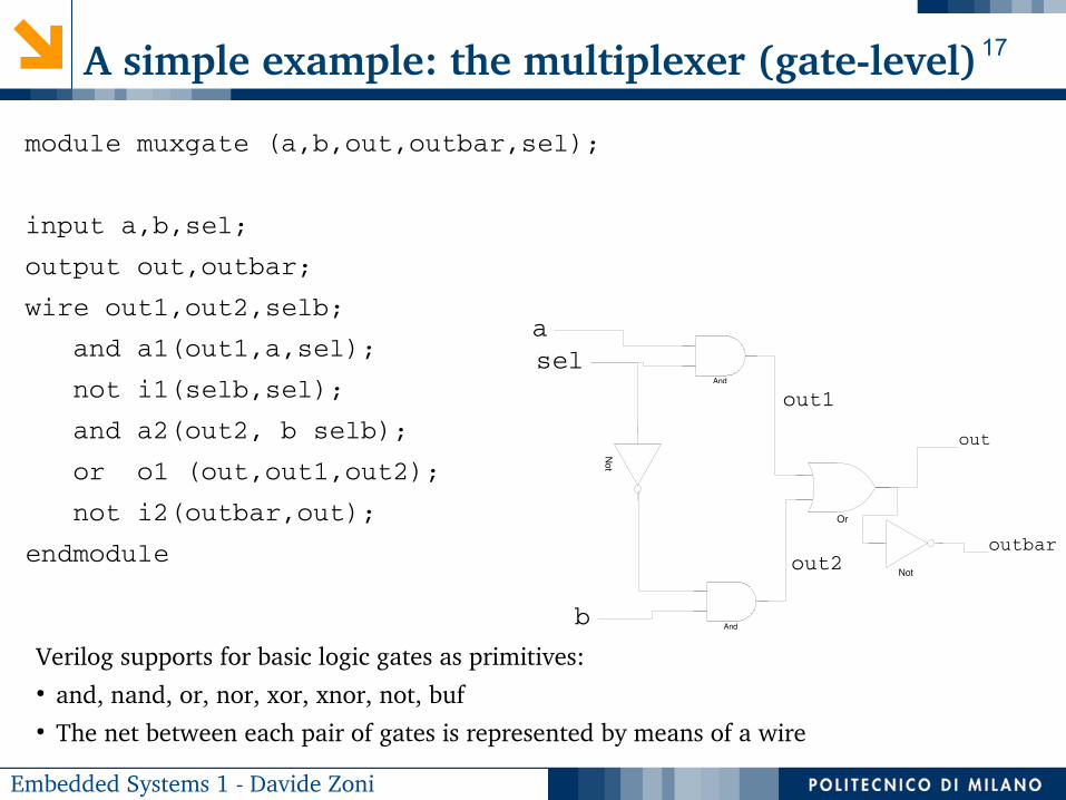
A simple example: the multiplexer (gatelevel)
module muxgate (a,b,out,outbar,sel);
input a,b,sel;
output out,outbar;
wire out1,out2,selb;
and a1(out1,a,sel);
not i1(selb,sel);
and a2(out2, b selb);
or o1 (out,out1,out2);
not i2(outbar,out);
endmodule
And
Or
Not
Not
And
sel
b
a
out1
out2outbar
out
Verilog supports for basic logic gates as primitives:● and, nand, or, nor, xor, xnor, not, buf● The net between each pair of gates is represented by means of a wire

18
Embedded Systems 1 Davide Zoni
A simple example: the multiplexer (dataflow)
module muxdataflow (a,b,out,outbar,sel);
input a,b,sel;
output out,outbar;
assign out = sel ? a : b;
assign outbar = ~out;
endmodule
Not
● Continuous assignments by using the assign keyword➔ models combinatorial logic in an easier way➔ The left side of the assign statement must be a wire➔ The right side can be both a reg or wire
● Dataflow operators➔ Conditional operator: (cond_expression) ? (value_if_true) : (value_if_false);➔ Arithmetic operator: +, , (do not use *, **, / in synthesizable code)➔ Boolean operator: ~, &, | , ^ [unary and binary version]
● Nested conditional operator (4:1 mux)➔ assign out = s1 ? (s0 ? i3 : i2) : (s0 ? i1 : i0);
b
a
sel
out
outbar

19
Embedded Systems 1 Davide Zoni
A simple example: the multiplexer (behavioral)
module muxbehavioral (a,b,out,
outbar,sel);
input a,b,sel;
output reg out, outbar;
always@(a,b,sel)
begin
if(sel)
out = a;
else
out = b;
outbar = ~out;
end
endmodule
Comments
● Anything assigned in an always block must be declared as reg
● always block is processed once whenever a signal in the sensitivity list changes value. Since Verilog2001 the sensitivity list can be substituted with a * to get all the wire/variables to whom the always has to be “sensitive” at
● Statements in the always block are executed sequentially. (Order matters!)
● The begin/end keyword pair is used to group multiple statements within the same always block. Actually they are equivalent with the { / } in C/C++ code

20
Embedded Systems 1 Davide Zoni
MixandMatch Assignments
module mux (a,b,out,outbar,sel);
input a,b,sel;
output reg out;
output outbar;
always@(a,b,sel)
begin
if(sel) out=a;
else out=b;
end
assign outbar = ~out;
endmodule
Not
● Defacto practice: procedural blocks and continuous assignments used side by side in the design of the same module
● Simulation viewpoint: procedural blocks and continuous assignments are evaluated in parallel➔ the order in the event processing is auto induced by the design, i.e. the always block is evaluated first
with respect to the continuous assignment because of a dependency (by construction)
● Do not assign the same reg twice or more (overdrive error)➔ The same for the continuous assignments
b
a
sel
out
outbar
21
Embedded Systems 1 Davide Zoni
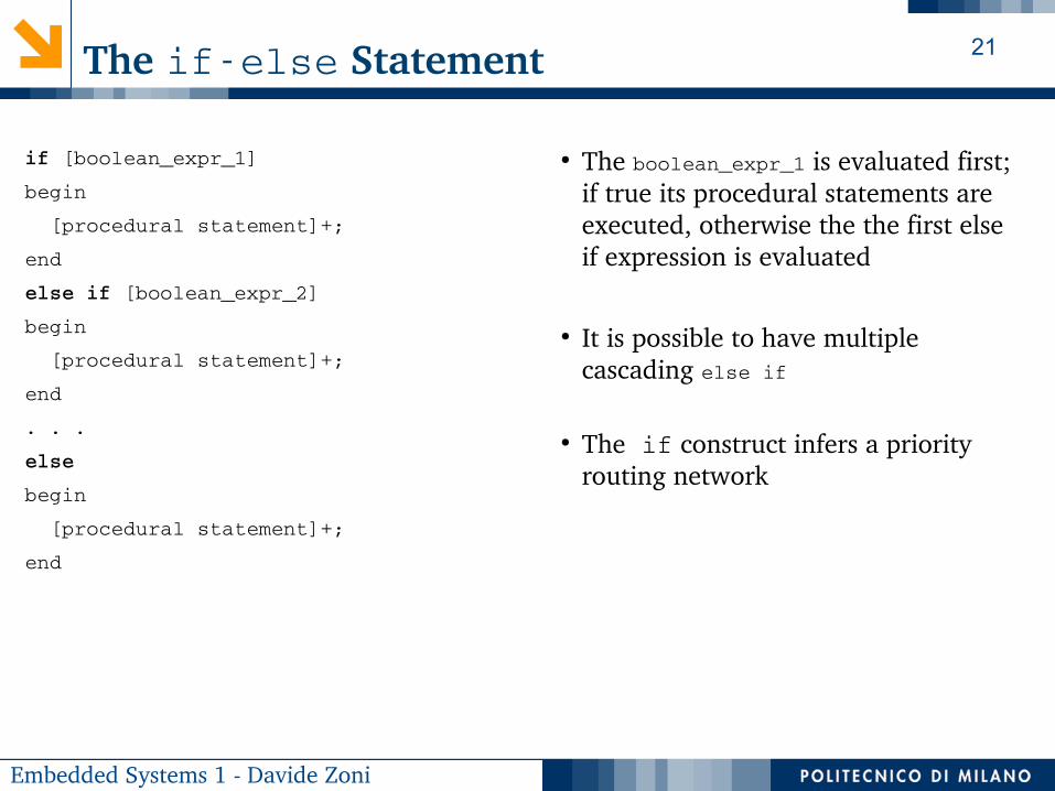
The ifelse Statement
if [boolean_expr_1]
begin
[procedural statement]+;
end
else if [boolean_expr_2]
begin
[procedural statement]+;
end
. . .
else
begin
[procedural statement]+;
end
● The boolean_expr_1 is evaluated first; if true its procedural statements are executed, otherwise the the first else if expression is evaluated
● It is possible to have multiple cascading else if
● The if construct infers a priority routing network
22
Embedded Systems 1 Davide Zoni
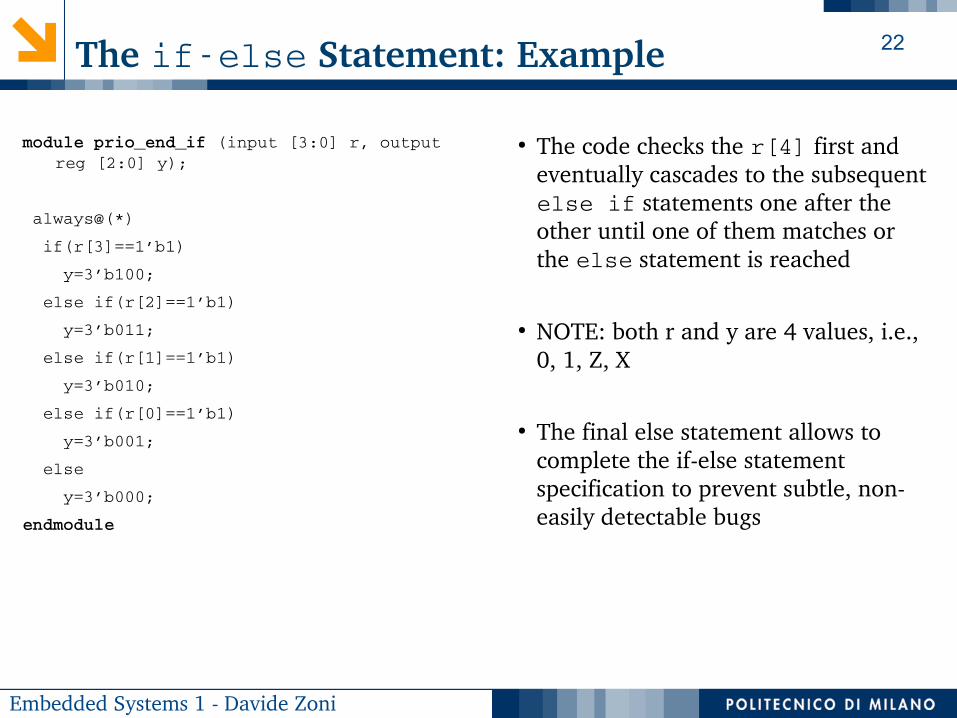
The ifelse Statement: Example
module prio_end_if (input [3:0] r, output reg [2:0] y);
always@(*)
if(r[3]==1’b1)
y=3’b100;
else if(r[2]==1’b1)
y=3’b011;
else if(r[1]==1’b1)
y=3’b010;
else if(r[0]==1’b1)
y=3’b001;
else
y=3’b000;
endmodule
● The code checks the r[4] first and eventually cascades to the subsequent else if statements one after the other until one of them matches or the else statement is reached
● NOTE: both r and y are 4 values, i.e., 0, 1, Z, X
● The final else statement allows to complete the ifelse statement specification to prevent subtle, noneasily detectable bugs

23
Embedded Systems 1 Davide Zoni
The case Statement
case [case_expr]
[item1]:
begin
[procedural statement]+;
end
[item2]:
begin
[procedural statement]+;
end
[item3]:
begin
[procedural statement]+;
end
. . .
default:
begin
[procedural statement]+;
end
endcase
● The case statement is a multiway decision statement that compares the [case_expr]with a number of items and execute the procedural statements of the first matching item
● In the case of multiple matching items only the procedural statements of the first one are executed
● It does not infer a priority network like the ifelse statement
● The default keyword is matched each time no item is matched. It is not mandatory to specify all the possible items

24
Embedded Systems 1 Davide Zoni
The case Statement: Example
module prio_enc_case(input [3:0] r, output reg [2:0] y
always@(*)
case(r) 4’b1000,4’b1001,4’b1010,4’b1011,4’b1100,4’b1101,4’b1110,4’b1111:
y=3’b100;
4’b0100,4’b0101,4’b0110,4’b0111:
y=3’b011;
4’b0010,4’b0011:
y=3’b010;
4’b0001:
y=3’b001;
4’b0000:
y=3’b000;
endcase
endmodule
● The case statement can mimic the priority enforced by the ifelse statement
➔ it seems a stretch
● The 0 and 1 values are not the only values the r and items can assume (hints: X and Z)
➔ Maybe a more flexible case statement can fit the task if the priority is necessary
➔ The non complete specification can be dangerous… (discussed after)

25
Embedded Systems 1 Davide Zoni
The casez and casex Statements
casez (expr)
3’bzzz: ...
3’b???: ...
3’b?zz: ...
endcase
● The casez statement is a multiway decision statement that allows the z value and ? character in the item expression as don’tcares
➔ It ignores each bit position with a Z➔ Use it for synthesis if necessary
● The casex statement is a multiway decision statement that allows the z and x values as well as the ? character in the item expression as don’tcares.
➔ It ignores each bit position with a Z or X➔ don’t use the casex statement due to its subtleties in
treating x values that can thus mask bugs➔ x value semantic is different between simulation and
synthesis
● NOTE:➔ casex and casez use the identity operator
(===)to compare the case_espr with each item
➔ casex and casez are symmetric since it does not matter if the special value/character appears in the item or in the case_espr
➔ ? is a placeholder / character; X / Z are values➔ The use of ? In the item is preferred than X /Z
EXAMPLE● Matching with multiple items is possible
➔ the first coming is selected one, thus inferring a priority network
● expr=3’bxxx➔ No match in the casez➔ Always match in the casex
expr=3’bzzz➔ Always match for both
casex (expr)
3’bzxz: ...
3’b???: ...
3’b?xx: ...
endcase

26
Embedded Systems 1 Davide Zoni
Inferred Unintended Latches in Comb. Circuits
module mux_wrong(input [1:0] sel, output reg [1:0] y
always@(*)
case(r)
2’b00: y=2’b00;
2’b01: y=2’b01;
2’b10: y=2’b10;
endcase
endmodule
● What we have when sel == 2’b11?➔ The old value. Is that what we
intended to infer? (probably not!)➔ We inferred an unintended latch to
eventually keep the old value
● The default special item can help preventing such a behavior
➔ Simulation: propagates the X and Z values thus eases the bug detection
➔ Synthesis: X values are optimized as treated as don’tcare
● The same for the ifelse statement➔ Use the else statement to catch all
not listed possibilities
module mux_correct(input [1:0] sel, output reg [1:0] y
always@(*)
case(r)
2’b00: y=2’b00;
2’b01: y=2’b01;
2’b10: y=2’b10;
default: y=2’bxx;
endcase
endmodule
Use the default special case item

27
Embedded Systems 1 Davide Zoni
Use parameters to improve the design flexibility
module mux #(parameter W=2)
(input [1:0] sel,
input [W1:0] a,
input [W1:0] b,
input [W1:0] c,
input [W1:0] d,
output reg [W1:0] y);
always@(*)
case(sel)
2’b00: y=a;
2’b01: y=b;
2’b10: y=c;
2’b10: y=d;
default: y={W{1’bx}};
endcase
endmodule
● The parameter keyword allows for a viable way to reuse the same design using
➔ Same behavior different signal widths
➔ Passing options to a design at the elaboration time
● NOTE: Sometimes the parameter alone is not enough to make the module flexible
➔ Hints: think about an Ninput mux where N is a parameter. The sel signal width becomes parametric...

28
Embedded Systems 1 Davide Zoni
Nested modules and parametersmodule mux #(parameter W=2)
(input [1:0] sel,
input [W1:0] a, input [W1:0] b,
input [W1:0] c, input [W1:0] d,
output reg [W1:0] y);
. . . //(defined as before)
endmodule
`define WGLOBAL 2
module parent(…)
wire [`WGLOBAL1:0] a,b,c,d,y;
wire sel[1:0];
mux #(.W(`WGLOBAL))
mux0(
.a(a), .b(b), .c(c), .d(d),
.sel(sel), .y(y)
);
… //rest of the parent module logic
endmodule
● The parameter keyword allows for a viable way to reuse the same design:
➔ Same behavior but different signal widths
➔ Passing options to a design at the elaboration time
● NOTE: Sometimes the parameter alone is not enough to make the module flexible
➔ Hints: think about an Ninput mux where N is a parameter. The sel signal width becomes parametric ...

29
Embedded Systems 1 Davide Zoni
From Combinatorial To Sequential Logic Circuits

30
Embedded Systems 1 Davide Zoni
Nonblocking VS Blocking Assignments
...
reg a[3:0];
reg b[3:0];
reg c[3:0];
always@(posedge clk)
begin
a <= b;
c <= a;
end
...
Afterwards a=3, c=2;
[nonblocking (<=)]
...
reg a[3:0];
reg b[3:0];
reg c[3:0];
always@(posedge clk)
begin
a=b;
c=a;
end
...
Afterwards a=3, c=3
[blocking (=)]
Beginning with a=2, b=3

31
Embedded Systems 1 Davide Zoni
Nonblocking VS Blocking Assignments
Blocking (=) and nonblocking (<=) assignments can be
used within the always block, only
Differences:● Blocking Assignment: evaluated (autoordered) one after the other● Nonblocking Assignment: within the same always block the right side of each
statement is frozen and it is used to update all the left side of the corresponding statement. Then, all the variables/signals are updated in parallel at once
Practical Usage Rules:● The standard allows to mix and match blocking and nonblocking assignments
together in the same always block● In this course it is mandatory to use:
➔ Combinatorial logic: blocking assignments only➔ Sequential logic: nonblocking assignments only

32
Embedded Systems 1 Davide Zoni
The flipflop
module ff(input clk, input d, output reg q);
always@(posedge clk)
begin
q<=d;
end
endmodule
module ff_en(input clk, input en, input d, output reg q);
always@(posedge clk)
begin
if(en)
q<=d;
end
endmodule
ffd
clk
q
ff_end
clk
q
en

33
Embedded Systems 1 Davide Zoni
The flipflop with (asynch/synch) reset
module ff_rst_a(input clk, input rst,
input d, output reg q);
always@(posedge clk, posedge rst)
begin
if(rst)
q<=d;
end
endmodule
module ff(input clk, input rst,
input d, output reg q);
always@(posedge clk)
begin
if(rst)
q<=d;
end
endmodule
ff_rst_a
d
clk
q
ff_rst_s
d
clk
q
rst
rst

34
Embedded Systems 1 Davide Zoni
The RegisterStandalone Component
module register #(parameter W=2)
(
input clk,
input [W1:0] d,
output reg [W1:0] q
);
always@(posedge clk)
begin
q <= d;
end
endmodule
They share the same semantic...
As made of ff modules
module register #(parameter W=2)
(
input clk,
input [W1:0] d,
output reg [W1:0] q
);
ff ff0(.clk(clk), .d(d), .q(q));
ff ff1(.clk(clk), .d(d), .q(q));
endmodule

35
Embedded Systems 1 Davide Zoni
More on the Nonblocking Assignments

36
Embedded Systems 1 Davide Zoni
Verilog for Design: An Example
...
wire [2:0] a_i, b_i, c_i;
reg [2:0] a, b, c;
always@(posedge clk)
begin
a <= a_i;
b <= a+1;
c <= b+1;
end
...
a_i
clk
+1 +1
A B C
● The order of the nonblocking assignments within the same always block does not matter
● The structure of the always makes the synthesizer to infer flipflops
c

37
Embedded Systems 1 Davide Zoni
Verilog for Design: A second coding style
...
wire [2:0] a_i, b_i, c_i;
reg [2:0] a, b, c;
always@(posedge clk)
begin
a <= a_i;
b <= b_i;
c <= c_i;
end
assign b_i = a + 1;
assign c_i = b + 1;
...
a_i
clk
+1 +1
A B C
● Same semantic; combinatorial logic is outside the always block
● The order of the non blocking assignment does not matter
c

38
Embedded Systems 1 Davide Zoni
Verilog for Design: A WRONG solution
...
wire [2:0] a_i, b_i, c_i;
reg [2:0] a, b, c;
always@(posedge clk)
begin
a <= a_i;
b <= b_i;
c <= c_i;
assign b_i = a + 1;
assign c_i = b + 1;
end
...
a_i
clk
+1 +1
A B C
● Syntactically NOT correct➔ Always blocks cannot contain continuous
assignment statements
c

39
Embedded Systems 1 Davide Zoni
Verilog for Design: A third coding style
...
wire [2:0] a_i, b_i, c_i;
reg [2:0] a, b, c;
always@(posedge clk)
a <= a_i;
always@(posedge clk)
b <= b_i;
always@(posedge clk)
c <= c_i;
assign b_i = a + 1;
assign c_i = b + 1;
...
a_i
clk
+1 +1
A B C
● Same (CORRECT) behavior➔ Concurrent (sequential) always blocks,
the same circuit is inferred
c

40
Embedded Systems 1 Davide Zoni
Verilog for Design: Another WRONG solution
...
wire [2:0] a_i, b_i, c_i;
reg [2:0] a, b, c;
always@(posedge clk)
begin
a = a_i;
b = b_i;
c = c_i;
end
assign b_i = a + 1;
assign c_i = b + 1;
...
a_i
clk
+1 +1
A B C
● Syntactically correct (it can be synthesized)● Semantically broken
➔ Blocking assignments do not reflect the intrinsic behavior of the sequential logic
➢ The order of the statements matters! ➔ Don’t use blocking assignments in sequential
logic● IT IS FORBIDDEN IN THIS COURSE
c

41
Embedded Systems 1 Davide Zoni
Verilog for Design: Simulation Hints
The simulator generates and processes the events following a strict policy
● For a sequential circuit
1) update the variables/wire in the combinatorial constructs:➢ Continuous assignments➢ always@(*)➢ NOTE: Recursive actions can happen
2) evaluate all the right hand of each nonblocking assignment (unordered), and defer the update of the left side of the statement
3) update the left side of the statement
More details in the next class (SystemVerilog for Verification)...

42
Embedded Systems 1 Davide Zoni
Finite State Machines

43
Embedded Systems 1 Davide Zoni
Finite State Machines (FSMs): Hello Worldmodule fsm_light(input clk,
input button,
output reg light);
wire light_next;
always@(posedge clk)
light <= light_next;
always@(*)
begin
//prevent unintended latches
//light_next = light;
if(button)
light_next=1’b1;
else
light_next=1’b0;
end
endmodule
D Q
clk
Hello World FSM● The FSM has two (unnamed) states: ON, OFF● The datapath uses the input to compute the next state● What about if button is X ?
➔ light_next = light; but the semantic is lost
light0
1
button
LIGHT=0 LIGHT=1
button=1
button=0
button=0 button=1
1’b0
1’b1

44
Embedded Systems 1 Davide Zoni
Finite State Machines (FSMs)
Mealy FSM● Output
➔ Depends on input and state➔ Not synchronized with the clock
➢ Temporarily unstable output➔ Changes during transitions
S0 S1
in/out
Moore FSM● Output
➔ Depends on state only➔ Associated with FSM states
S0
out0
S1
out1
in
NextState
Comb
Logic ss
inputs
clk
D Q
Moore
Output
Logic
Mealy
Output
Logicss_next
ss_reg
Moore
output
Mealy
output

45
Embedded Systems 1 Davide Zoni
The Simple Vending Machine Example
Problem Specification:● No change (sorry I’m too simple :p)● Product delivery after inserting 0.3 . Single product€● Accepted Coins 0.1 0.2 . Single coin slot€ €● The Hard Reset input signal resets the vending machine● Single idle cycle after completing one transaction● No X at the FSM primary inputs (ideal scenario for now)
Coin
Sensor
And MechanismFSM
Comb+Seq
Logic
0.1€
0.2€
reset
clock
open Delivery
Mechanism
coin product

46
Embedded Systems 1 Davide Zoni
Simple Vending Machine: Moore FSMmodule fsm_moore(input clk, input rst, input ten_i, input twenty_i
output open_o);
reg [1:0] ss;
localparam IDLE=2’b00, TEN=2’b01, TWENTY=2’b10, OPEN_CMD=2’b11;
always@(posedge clk)
begin
if(rst) ss<=0;
else
begin
case(ss)
IDLE: if(ten_i) ss<=TEN;
else if(twenty_i) ss<=TWENTY;
else ss<=IDLE;
TEN: if(ten_i) ss<=TWENTY;
else if(twenty_i) ss<=OPEN_CMD;
else ss<=TEN;
TWENTY: if(ten_i) ss<=OPEN_CMD;
else if(twenty_i) ss<=OPEN_CMD;
else ss<=TWENTY;
OPEN_CMD: ss<=IDLE; //send an impulse only
endcase //endcase
end //endif
end //end always
assign open = (ss==OPEN_CMD);
endmodule
IDLE TEN
TWENTYOPEN_CMD
ten_i
ten_i
twenty
ten_i ||
twenty
twenty
twenty_i=X
&& ten_i=X
Simplifications● Leave one clock cycle before two transactions
➔ (to not bother the state diagram with additional arrows)● Assume no X can appear as primary input to the FSM. The X means don’t
care in the state diagram
twenty_i=0
|| ten_i=0

47
Embedded Systems 1 Davide Zoni
Simple Vending Machine: Mealy FSM (noopt)module fsm_moore(input clk, input rst, input ten_i, input twenty_i
output reg open_o);
reg [1:0] ss, ss_next;
localparam IDLE=2’b00, TEN=2’b01, TWENTY=2’b10, OPEN_CMD=2’b11;
always@(posedge clk)
ss<=ss_next;
always@(twenty_i, ten_i, ss, rst)
begin
if(rst) begin ss_next=0; open=0; end
else
begin
case(ss)
IDLE: begin
open=0;
if(ten_i) ss_next=TEN;
else if(twenty_i) ss_next=TWENTY;
else ss_next=IDLE;
end
TEN: begin
open=0;
if(ten_i) ss_next=TWENTY;
else if(twenty_i) ss_next=OPEN_CMD;
else ss_next=TEN;
end
TWENTY: begin
open=0;
if(ten_i) ss_next=OPEN_CMD;
else if(twenty_i) ss_next=OPEN_CMD;
else ss_next=TWENTY;
end
OPEN_CMD: begin ss_next=IDLE; open=1;end //send an impulse only
endcase //endcase
end //endif
end //end always
endmodule
IDLE TEN
TWENTYOPEN_CMD
ten_i/0
ten_i/0
twenty/0
ten_i ||
twenty
/0
twenty/0
twenty_i=X
&& ten_i=X
/1
twenty_i=0
|| ten_i=0
Simplifications● Not optimized● Assume no X can appear as primary input to the FSM. ● The X means don’t care in the state diagram

48
Embedded Systems 1 Davide Zoni
Simple Vending Machine: Mealy FSMmodule fsm_moore(input clk, input rst, input ten_i, input twenty_i
output reg open_o);
reg [1:0] ss, ss_next;
localparam IDLE=2’b00, TEN=2’b01, TWENTY=2’b10, OPEN_CMD=2’b11;
always@(posedge clk)
ss<=ss_next;
always@(twenty_i, ten_i, ss, rst)
begin
if(rst) begin ss_next=0; open=0; end
else
begin
case(ss)
IDLE: begin
open=0;
if(ten_i) ss_next=TEN;
else if(twenty_i) ss_next=TWENTY;
else ss_next=IDLE;
end
TEN: begin
open=0;
if(ten_i) ss_next=TWENTY;
else if(twenty_i) begin ss_next=IDLE; open=1; end
else ss_next=TEN;
end
TWENTY: begin
open=0;
if(ten_i || twenty_i) begin ss_next=IDLE; open=1; end
else ss_next=TWENTY;
end
endcase //endcase
end //endif
end //end always
endmodule
IDLE TEN
TWENTY
ten_i/0
ten_i/0
twenty/1
ten_i ||
twenty
/1twenty/0
twenty_i=0
|| ten_i=0
Simplifications● The Mealy FSM is faster and requires less states, in general
compared with the equivalent Moore one● Assume no X can appear as primary input to the FSM. ● The X means don’t care in the state diagram

49
Embedded Systems 1 Davide Zoni
An Rising Edge Detector (Moore)
The rising edge detector is a circuit that generates a short oneclockcycle tick when the input signal changes from 0 to 1
POSSIBLE USAGE:identify the onset of a slow timevarying input signal
module edge_detector_moore
(
input clk,input rst,
input level,
output reg tick
);
localparam [1:0] ZERO=2’b00, EDGE=2’b01, ONE= 2’b10;
reg [1:0] ss, ss_next;
// FSM state register update
always@(posedge clk,posedge rst)
if(rst) ss<=zero;
else ss<=ss_next;
cont’d
cont’d here
// combinatorial logic
always@(*)
begin
ss_next=ss; tick=1’b0;
case(ss)
begin
ZERO: if(level) ss_next=edge;
EDGE: begin
tick=1’b1;
if(level) ss_next=one;
Else ss_next= zero;
end
ONE: if(~level) ss_next=zero
default: ss_next=zero;
end
end
endmodule
ZERO
tick=0
EDGE
tick=1
level
ONE
tick=0
level
~level
~level

50
Embedded Systems 1 Davide Zoni
An Rising Edge Detector (Mealy)
The rising edge detector is a circuit that generates a short oneclockcycle tick when the input signal changes from 0 to 1
POSSIBLE USAGE:identify the onset of a slow timevarying input signal
module edge_detector_moore
(
input clk,input rst,
input level,
output reg tick
);
localparam ZERO=1’b0, ONE= 1’b1;
reg [1:0] ss, ss_next;
// FSM state register update
always@(posedge clk,posedge rst)
if(rst) ss<=zero;
else ss<=ss_next;
cont’d
cont’d here
// combinatorial logic
always@(*)
begin
ss_next=ss; tick=1’b0;
case(ss)
begin
ZERO: if(level) begin
ss_next=ONE;
tick=1’b1;
end
ONE: if(~level) ss_next=zero;
default: ss_next=zero;
end
end
endmodule
ZERO ONE
level/tick=1level
~level

51
Embedded Systems 1 Davide Zoni
Tools

52
Embedded Systems 1 Davide Zoni
Behavioral Simulation and Waveform Analysis
● CADENCE (ASIC flow)➔ ncsim RTL simulator➔ Simvision
● Xilinx (FPGA flow)➔ Vivado
➢ xvlog, xelab, compile and elaborate the design➢ xsim simulator with integrated waveform analyzer
➔ ISE➢ GUIbased flow➢ The commandline tools are not user friendly
● Open Source (Behavioral Simulation)➔ Icarus verilog (Verilog 2001 simulator)➔ Gtkwave waveform analyzer