embedded linux router
TRANSCRIPT
Patrick Kagechu
Embedded Linux Router
Helsinki Metropolia University of Applied Sciences
Degree Bachelor of Engineering
Degree Programme Information Technology
Thesis
19th December 19, 2012

Abstract
Author Title Number of Pages Date
Patrick Kagechu Embedded Linux Router 27 pages + 9 appendices 5 May 2010
Degree Bachelor of Engineering
Degree Programme Information Technology
Specialisation option Network, Embedded Engineering
Instructor
Matti Puska, Principal Lecturer
The goal of project was to show that a working router could be developed using readily available embedded devices and readily available software under the Linux operating sys-tem. The project also brought two multi-disciplines together, which are networking and embedded engineering. The project also tried to highlight the reusability of readily availa-ble software that is on the Internet. The project was carried out firstly by defining the functions a router does and which func-tions are meant for industrial and small home routers: the additional services it needs to offer more value to the user and later defining the software and drivers needed for all this to be able to work properly. The additional software installed were Webmin for providing a graphical user interface and a way of configuring the dreamplug, bird routing software for handling the dynamic routing protocols. The other applications used were word editors for editing the configuration files. The functionality of the router was tested both through systematic troubleshooting of the network files some of which, with any change made were fatal while others rendered the dreamplug unresponsive. The router worked and some of the tools used were iperf, netstat, ipconfig among those found in the Linux networking utilities. The results showed that the dreamplug can handle as much as necessary for a Small Of-fice Home Office type of ecosystem. The project also showed that there is more than openly available software to ensure proper running and routing of software.
Keywords Open source, Linux, bird, Webmin, protocol

Contents
1 Introduction 1
2 Routing 2
2.1 Router 3
Routing table 4
2.2 Internet Protocol 5
2.2.1 Forwarding of Packet 6
2.2.2 Verification Process 6
2.3 Internet Control Message Protocol 8
2.4 Internet Protocol Security (IPsec) 10
IPsec Workings 11
2.5 Routing Protocols 12
3 Router Platforms 13
3.1 Router Operating Systems 13
3.2 Dreamplug 14
3.2.1 Hardware 14
3.2.2 Firmware 15
3.3 Linksys WRVS4400N 16
3.4 Ethernet over USB Adapter 17
4 Software 18
4.1 Linux as a Network Operating System (NOS) 18
4.2 Bird Internet Routing Daemon 19
4.3 Webmin 20
4.4 Sound Module 21
5 International Intensive Program (IP DOSSEE) 22
6 Testing 25
7 Conclusion 32
References 33

Appendices
Appendix 1. BIRD Configuration file
Appendix 2. Debian Ubuntu OS change
Appendix 3. Network Testing
Appendix 4. Wireless LAN Testing
Appendix 5. Services Test
Appendix 6. Webmin

1
1 Introduction
The project answered to the question, if it is possible to come up with a functioning
router using an embedded device. This idea has taken ground from the fact that tech-
nology has enabled advancement in embedded development leading to miniaturization
of electronic devices. The current technology world initiative is to open-source soft-
ware, hence decidedly opted to run the router with readily available open source con-
tent. For technocrats and hobbyist setting up the dreamplug as router or media server
would be the ultimate project though capability and efficiency of the router should be at
per with commercially available ones.
The router device of choice should be robust enough to meet the requirements of a
Small Office/Home Office (SOHO) router. The router device should be able to work
within an autonomous network supporting multiple computer devices both wired and
wireless. The device should be scalable and could be used at various parts of the net-
work. That is extending provision of network services through cable and Wireless Local
Area Network (WLAN) also termed as ‘Wi-Fi’. The support for the wide range of Inter-
net Protocols (IP) and other router devices of other vendors and manufactures is par-
amount.
The scope of the report covers the software, modules and the hardware used for the
project. The report also covers the results from an international team selected to im-
plement the defined technical plan and to test the device. Further tests were carried out
to compare the device with a commercially available router of choice. Future develop-
ments which could be carried out with the device of choice are also discussed. The
miniaturization of the router devices leads to introduction of the concept of ‘plug com-
puter’ since the size is the same as that of the power plug.
2
2 Routing
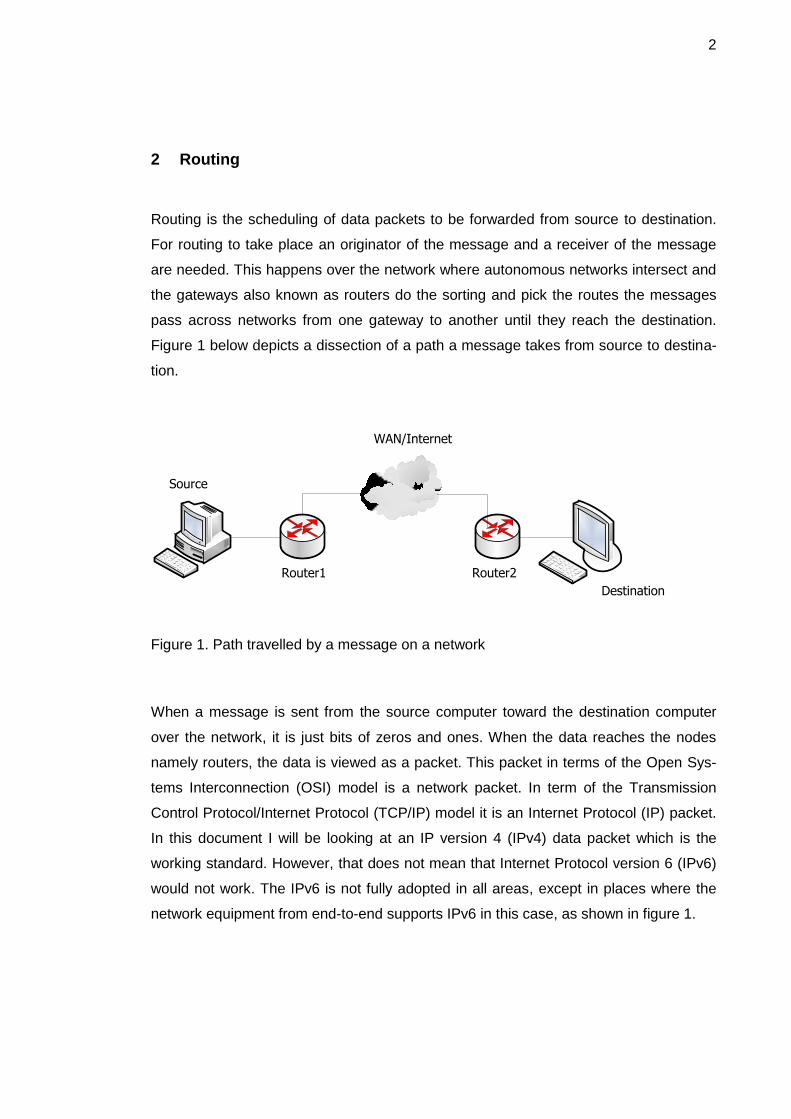
Routing is the scheduling of data packets to be forwarded from source to destination.
For routing to take place an originator of the message and a receiver of the message
are needed. This happens over the network where autonomous networks intersect and
the gateways also known as routers do the sorting and pick the routes the messages
pass across networks from one gateway to another until they reach the destination.
Figure 1 below depicts a dissection of a path a message takes from source to destina-
tion.
WAN/Internet
Router1 Router2
Source
Destination
Figure 1. Path travelled by a message on a network
When a message is sent from the source computer toward the destination computer
over the network, it is just bits of zeros and ones. When the data reaches the nodes
namely routers, the data is viewed as a packet. This packet in terms of the Open Sys-
tems Interconnection (OSI) model is a network packet. In term of the Transmission
Control Protocol/Internet Protocol (TCP/IP) model it is an Internet Protocol (IP) packet.
In this document I will be looking at an IP version 4 (IPv4) data packet which is the
working standard. However, that does not mean that Internet Protocol version 6 (IPv6)
would not work. The IPv6 is not fully adopted in all areas, except in places where the
network equipment from end-to-end supports IPv6 in this case, as shown in figure 1.
3
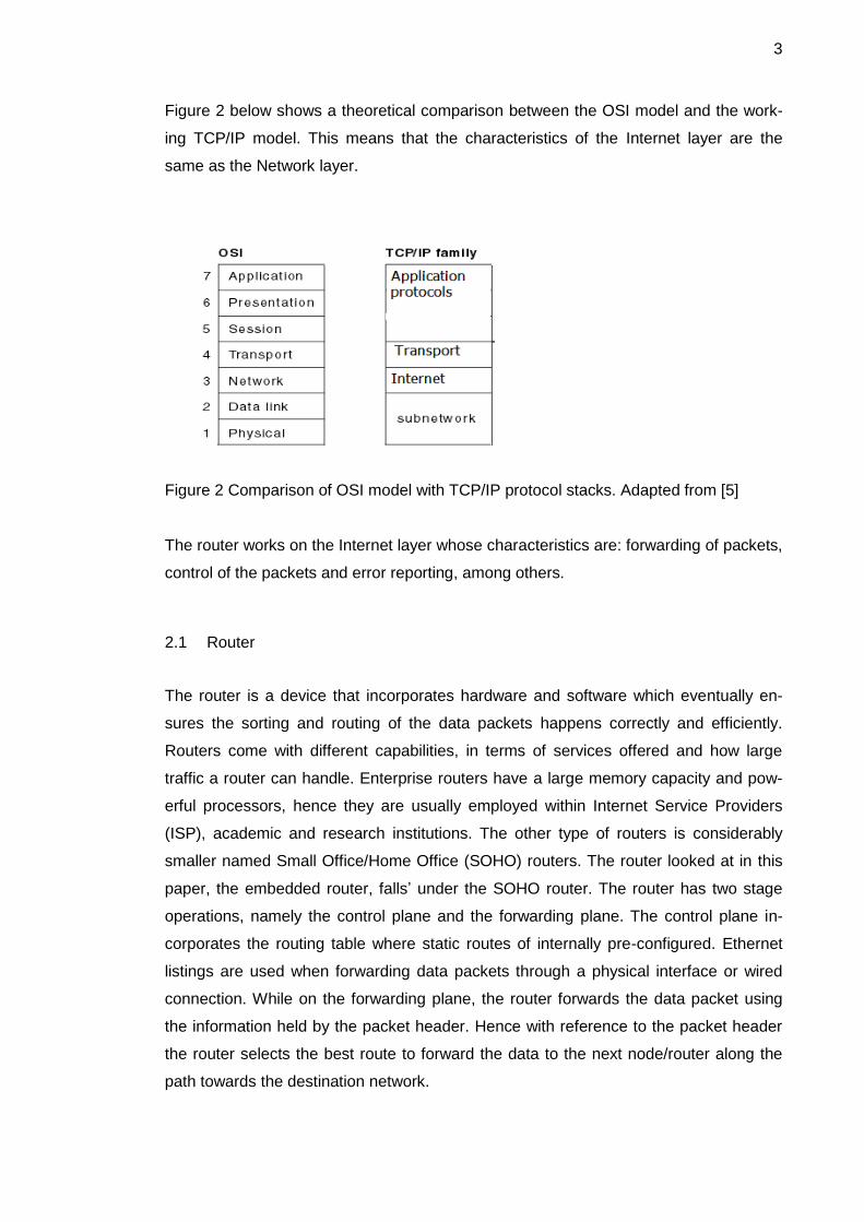
Figure 2 below shows a theoretical comparison between the OSI model and the work-
ing TCP/IP model. This means that the characteristics of the Internet layer are the
same as the Network layer.
Figure 2 Comparison of OSI model with TCP/IP protocol stacks. Adapted from [5]
The router works on the Internet layer whose characteristics are: forwarding of packets,
control of the packets and error reporting, among others.
2.1 Router
The router is a device that incorporates hardware and software which eventually en-
sures the sorting and routing of the data packets happens correctly and efficiently.
Routers come with different capabilities, in terms of services offered and how large
traffic a router can handle. Enterprise routers have a large memory capacity and pow-
erful processors, hence they are usually employed within Internet Service Providers
(ISP), academic and research institutions. The other type of routers is considerably
smaller named Small Office/Home Office (SOHO) routers. The router looked at in this
paper, the embedded router, falls’ under the SOHO router. The router has two stage
operations, namely the control plane and the forwarding plane. The control plane in-
corporates the routing table where static routes of internally pre-configured. Ethernet
listings are used when forwarding data packets through a physical interface or wired
connection. While on the forwarding plane, the router forwards the data packet using
the information held by the packet header. Hence with reference to the packet header
the router selects the best route to forward the data to the next node/router along the
path towards the destination network.
4
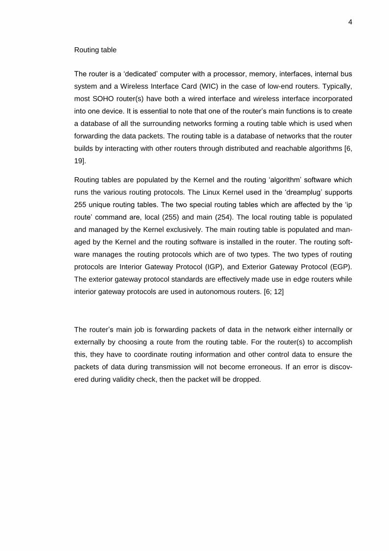
Routing table
The router is a ‘dedicated’ computer with a processor, memory, interfaces, internal bus
system and a Wireless Interface Card (WIC) in the case of low-end routers. Typically,
most SOHO router(s) have both a wired interface and wireless interface incorporated
into one device. It is essential to note that one of the router’s main functions is to create
a database of all the surrounding networks forming a routing table which is used when
forwarding the data packets. The routing table is a database of networks that the router
builds by interacting with other routers through distributed and reachable algorithms [6,
19].
Routing tables are populated by the Kernel and the routing ‘algorithm’ software which
runs the various routing protocols. The Linux Kernel used in the ‘dreamplug’ supports
255 unique routing tables. The two special routing tables which are affected by the ‘ip
route’ command are, local (255) and main (254). The local routing table is populated
and managed by the Kernel exclusively. The main routing table is populated and man-
aged by the Kernel and the routing software is installed in the router. The routing soft-
ware manages the routing protocols which are of two types. The two types of routing
protocols are Interior Gateway Protocol (IGP), and Exterior Gateway Protocol (EGP).
The exterior gateway protocol standards are effectively made use in edge routers while
interior gateway protocols are used in autonomous routers. [6; 12]
The router’s main job is forwarding packets of data in the network either internally or
externally by choosing a route from the routing table. For the router(s) to accomplish
this, they have to coordinate routing information and other control data to ensure the
packets of data during transmission will not become erroneous. If an error is discov-
ered during validity check, then the packet will be dropped.
5
2.2 Internet Protocol
IP is the main protocol which establishes the Internet. As per the TCP/IP model, it
takes the transport layer data packets and cloaks them with the Internet layer header
information, adding a way in which the data packets can navigate the Internet. The
Internet layer header introduces the Internet address to the data packet and this en-
sures that the data packet can navigate the network until it locates the host or it is
dropped if the Time-To-Live (TTL) count is reached. This is how the routers are able to
route data from source to destination by use of addresses incorporated in the header of
the data packet being forwarded through the outgoing interface of the router. The IP
layer provides connectionless (datagram) service that is, the Internet protocol works
like a postal service, meaning that the parcel which is the datagram is sent without a
direct link between the source and destination from router to router until it reaches the
destination address. The router receives a data packet, in this case an Internet Proto-
col Version 4 (IPv4) packet and checks for the best route from the local routing table
and forwards the data packet to the next hop node. Below there is a brief explanation
of how the router goes about this process of forwarding. [6, 70-83; 19]

6
2.2.1 Forwarding of Packet
The IP header is made of a minimum of five words of 32 bits each with the options and
padding part varying between 0 – 10 words of 32 bits each. This makes the size of the
header to have a minimum of 20 bytes and a maximum of 60 bytes.
Figure 3. IPv4 Header Format. Adapted from [19]
As shown by the IP header in figure 3, the four main key mechanisms it uses to offer
delivery service are: Type of Service (TOS), Time to Live (TTL), header checksum and
options. [19]
2.2.2 Verification Process
An IPv4 router on receiving a data packet does the following: (with reference to figure
3)
1. The router verifies the header is valid by running the following test;
i. The packet length is the legal minimum of the IP datagram that is 20
bytes.
ii. The IP checksum is correct.
iii. The IP version number is four (4).
iv. The IP Header Length (IHL) field is large enough to hold the minimum
length of 5 words of 32 bits each.
v. The IP total length field is large enough to hold the IP header datagram
stated in the IHL. [6, 66]

7
2. Secondly the router must confirm if the destination address is local or not. Ei-
ther picking an outgoing interface or delivering the IPv4 packet to the local net-
work, the packet can be handled in one of the three ways:
i. If the data packet is meant for the local network, it is queued for the de-
livery.
ii. After the routing decision is made, the router picks the outgoing inter-
face by checking the routing table, and the data packet is queued for
forwarding.
iii. Lastly if it is a multicast packet, it is queued for local delivery and a copy
queued for forwarding.
3. When the packet is confirmed that it is not meant for the local network, the rout-
er decrements the Time to Live (TTL) count.
4. If the data packets are for the routers’ local network, the router updates the
timestamp counter. However in the case of the external network, the router
does not update the header timestamp counter. [6, 68-69]
The above verification procedure happens for all packet types; unicast, multicast and
broadcast alike. Though there are several differences when it comes to the individual
set of messages.
Unicast messages are meant for a single recipient and they are briefly explained be-
low.
I. The forwarder (router) of the message determines the next hop by checking the
routing table.
II. During determining the route, the router also determines the network and the
output interface to send the packet to.
III. The router also confirms that the source and destination address are valid.
IV. The router next decrements the TTL count from the packet header.
V. The router then queues the packet for forwarding as in the verification part 2(iii).
VI. If the packet is bigger than the transmitting media, fragmentation is done but
only after the outgoing interface has been picked, so that all the packets can
have the same route of destination.
VII. Then the router determines the link layer address of the packet’s next hop that
is, the physical address of the interface the packet is to go through.
VIII. The IP datagram header is then encapsulated to the message/data and queued
for forwarding to the outgoing interface.

8
IX. Lastly the router sends an Internet Control Message Protocol (ICMP) redirect if
necessary. To redirect is where the router informs the host to pick another route
for certain messages. [6, 63-64]
2.3 Internet Control Message Protocol
The Internet is made up of inter-joined networks. The interconnection is made possible
with the use of gateways (routers). The Internet Protocol (IP) is used for host-to-host
datagram service which is not designed to be reliable. The gateways communicate with
each other through a gateway to gateway protocol (GGP) for control purposes. The
main purpose of ICMP is to give feedback to the source host about the communication
environment. This could be an error which the gateway/router considers necessary to
communicate to the originator, host so that the issue can be corrected. [6, 51-52]
The ICMP messages can be grouped into two categories:
ICMP error messages
o Destination unreachable
o Redirect
o Source Quench
o Time Exceeded
o Parameter problem
ICMP query messages
o Echo
o Information
o Timestamp
o Address mask
o Router discovery
By default ICMP error messages have the same Type of Service (TOS) as the trigger-
ing packet, unless by doing so it would lead to them being dropped. Then the value
would be set to zero. [6, 51-52]

9
Figure 4 below shows the IP fields of a Destination Unreachable Message which is
attached with the header of the packet which triggered the destination unreachable to
be generated.
Figure 4. Destination Unreachable Message of the ICMP [20, 3]
The message is generated by the router if the router does not have a route to the des-
tination address of the network embedded in the packet. This also includes the router
not having a default route where all packets are usually forwarded. Also the message
can be generated if the Type of Service (TOS) of the link is not default, which is (0000).
Secondly, if the TOS link to the next-hop is not the same as the TOS of the data pack-
et, then the router generates a ICMP message whose code is 0 (network unreachable).
The ICMP message is required to have as much information as that of the triggering
packet as long as it does not go beyond 576 bytes. This ensures that the host origina-
tor of the message understands the environment that leads to the generation of the
ICMP message. It is also essential to note that some of the utilities are based on the
ICMP message, such as ping which makes use of echo request/reply message. The
traceroute utility, which is based on echo, messages that is, making use of the time-to-
live (TTL), between the hosts. [6, 55-56; 20, 4]
10
2.4 Internet Protocol Security (IPsec)
The Internet layer has a security protocol whose main purpose is to authenticate and
encrypt all IP packets of a communication session. The security protocol IPsec pro-
vides protection for all data packets in the Internet layer. The IPsec security protocols
create a boundary where the traffic traversing across the interfaces is subjected to the
access controls set by the administrator. The security scheme protection runs from
end-to-end, meaning it protects data from a pair of hosts (host-to-host), a pair of securi-
ty gateways (network-to-network), and/or between gateway and host (network-to-host).
The IPsec provides high-quality cryptographic-based security for both IPv4 and IPv6
data packets. IPsec also offers additional security services, namely access control,
connectionless integrity, data origin authentication, detection and rejection of replays,
confidentiality through encryption and limited traffic flow confidentiality. All these ser-
vices offer security for all the protocols in the application layer and transport layer ac-
cording to figure 2. [33]
The IPsec protocol has two traffic security protocols, the Authentication Header (AH),
and Encapsulation Security Payload (ESP), and also automatic key management pro-
tocols which are Internet Key Exchange (IKE and IKEv2). When the IPsec is correctly
implemented and deployed, the firewall functionality should not adversely affect the
users, host and other Internet components that do not employ IPsec. The IPsec securi-
ty protocols AH and ESP and to some extent IKE are designed to be undeterred by the
cryptographic algorithms. That said assumptions are that effectiveness of IPsec de-
pends on the operating environment that it operates in. This means that defects in the
OS security, poor quality of random number sources, and sloppy system management
practices can adversely affect the workings of the IPsec. [33]
IPsec implementation works in a host or in an intermediary device such as a security
gateway, implementing IPsec for example a firewall or a router that has IPsec enabled.
The requirements that IPsec is based upon are defined by a Security Policy Database
(SDP) which is established and maintained by the user, administrator or by an applica-
tion which works within the constraints of the user/administrators. The IP packets under
the IPsec security services are either DISCARDed or allowed to BYPASS IPsec protec-
tion or PROTECTed by the IPsec, as defined by the SDP policies. [33]

11
IPsec Workings
IPsec creates a boundary between the unprotected and protected interfaces, for the
host or network. The data traffic going through this boundary is subject to the access
control specified by the user or administrator and may either go unimpeded or dropped
or afforded the security services of AH and ESP. IPsec can protect:
i. Between pairs of host
ii. Between a pair of security gateways
iii. Between a security gateway and a host.
A host compliant supports the first and third forms of connectivity while a compliant
gateway security device should support all three types of connectivity. The terms used
by traffic moving from the unprotected implementation to the protected is said to be
‘inbound’, while traffic moving from protected to unprotected is said to be ‘outbound’.
This setup could be inside a host where the boundary is across a port. [33]
The IPsec security protocols provide traffic security and have different specializations.
AH offers integrity and data origin authentication and ESP offer the same set of ser-
vices as AH and also confidentiality. ESP is a compulsory provision in IPsec implemen-
tation while AH is optional. Where the ESP is used with confidentiality enabled, there is
provision for limited traffic flow confidentiality, that is, concealing packet length which is
effective in the Virtual Private Network (VPN). Both AH and ESP provide access control
whose distribution of cryptographic keys and management flows are dictated by the
Security Policy Database (SPD). The IPsec security protocols AH and ESP can both be
applied individually. Each of them supports two modes of use, transport mode and tun-
nel mode. In transport mode they provide protection to the transport layer while in tun-
nel mode they are applied to the tunnel IP packets. The implementation of the IPsec
can be done in conjunction with a host, or a router or a firewall to create security gate-
way or an independent device. [33]

12
2.5 Routing protocols
Routing protocols are standards or formats that have been put in place, so that the
routers irrespective of the manufacturer can be able to communicate with each other
and share information of the changes in the network. A router used in an Autonomous
System (AS) network normally has static routing and dynamic routing to comply with.
Static routing is when the information in the link has been manually configured, thus no
change is expected. Dynamic routing usually incorporates protocol algorithm which
adjusts the routing table entries with each change in the network. There are three clas-
ses of dynamic protocols:
Interior Gateway Protocol (IGP) using the link-state protocol which is based on
Dijkstra’s algorithm.
Interior gateway protocol using the distance-vector protocol which is based on
Bellman-Ford algorithm and
Exterior Gateway Protocol (EGP) for inter-Autonomous system routing.
For a home or small office router, the interior gateway protocol class category is para-
mount as a requirement of a SOHO router. A router implementing any routing protocol
besides static routes, should be able to run Open Shortest Path First version 2
(OSPFv2) in addition to the other IGPs. [6]
The IGP routing protocol function within an autonomous system should ensure fast
convergence, that is, any network change is updated in the routing table as quickly as
possible. The inter-routing advertising information should be as minimal as possible, so
as not to over-clog the link bandwidth. Lastly, the protocol should provide equal costing
of the routes to enable load splitting. The router should also provide some means of
management which in this project is the use of ‘Webmin’ which is introduced in chapter
4. The router should support also Simple Network Management Protocol (SNMP),
which is an application layer protocol same as the routing protocols. [6]

13
3 Router Platforms
Platforms are the underlying hardware and or software which determine how a com-
puter is used or can be used and which software can be used or installed. Router plat-
forms are dependent of the hardware, that is, the processor and the embedded operat-
ing system running in them. [7]
3.1 Router Operating Systems
Router platforms and router Operating Systems (OS) are therefore tied together and
named depending on the hardware and operating system deployed in the routers. The
list below is not conclusive but includes some of the most active platforms:
Network Operating System (NOS)
Junos
Cisco IOS (formerly Internetworking Operating System).
Extensible Open Router Platform (XORP).
A Router is an embedded device running a customized operating system whose main
function is to share resources among the attached computers. The OS has to manage
users, groups, data and other resources, hence increasing the throughput of the IP
datagram forwarding and managing the bandwidth efficiently. If the operating system
implements the TCP/IP protocol stack suite and supports programs and utilities such
as iproute2, ping and traceroute and most importantly runs a dialoguer which manages
resources of the system, then it can be termed to be a NOS. In this report, the operat-
ing system of choice is Linux, which is of Ubuntu distribution and does support net-
working features. The other examples of NOS, though not embedded systems are Mi-
crosoft Windows Server 2003, Microsoft Windows Server 2008, UNIX, Mac OS X,
Novell NetWare and Berkley Software Distribution (BSD).
14
3.2 Dreamplug
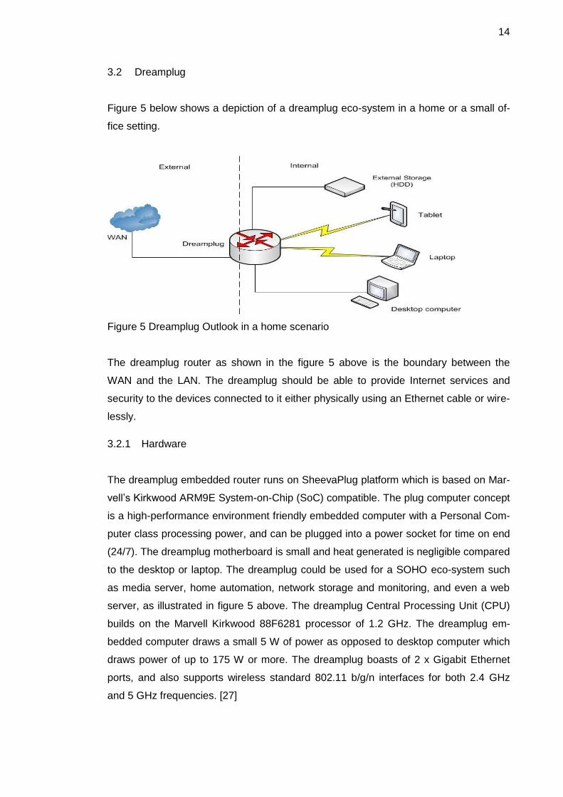
Figure 5 below shows a depiction of a dreamplug eco-system in a home or a small of-
fice setting.
Figure 5 Dreamplug Outlook in a home scenario
The dreamplug router as shown in the figure 5 above is the boundary between the
WAN and the LAN. The dreamplug should be able to provide Internet services and
security to the devices connected to it either physically using an Ethernet cable or wire-
lessly.
3.2.1 Hardware
The dreamplug embedded router runs on SheevaPlug platform which is based on Mar-
vell’s Kirkwood ARM9E System-on-Chip (SoC) compatible. The plug computer concept
is a high-performance environment friendly embedded computer with a Personal Com-
puter class processing power, and can be plugged into a power socket for time on end
(24/7). The dreamplug motherboard is small and heat generated is negligible compared
to the desktop or laptop. The dreamplug could be used for a SOHO eco-system such
as media server, home automation, network storage and monitoring, and even a web
server, as illustrated in figure 5 above. The dreamplug Central Processing Unit (CPU)
builds on the Marvell Kirkwood 88F6281 processor of 1.2 GHz. The dreamplug em-
bedded computer draws a small 5 W of power as opposed to desktop computer which
draws power of up to 175 W or more. The dreamplug boasts of 2 x Gigabit Ethernet
ports, and also supports wireless standard 802.11 b/g/n interfaces for both 2.4 GHz
and 5 GHz frequencies. [27]

15
The Ethernet and Wi-Fi interface give the dreamplug an edge as a router for it can
support two or more networks, as depicted by figure 5 above. The router setup above
has the external network that is a Wide Area Network (WAN) or the Internet and the
internal Local Area Network (LAN). The dreamplug can also support smart devices
which have wireless capabilities or Bluetooth capabilities. The dreamplug has two Uni-
versal Serial Bus (USB) ports and one external Serial Advanced Technology Attach-
ment (e SATA) 2.0 port, and Secure Digital (SD) card socket. The USB ports can be
used to increase the dreamplug Ethernet interfaces by using Ethernet over USB adapt-
er if extra Ethernet interfaces are needed. [15]
3.2.2 Firmware
The dreamplug ships with a Linux Kernel and a firmware installed. A firmware is a
combination of hardware and software, that is, memory space, program code and
stored data. The firmware software is embedded in a non-volatile memory that is Read
Only Memory (ROM). The program mostly is not upgradeable during the lifetime of the
device but there are some cases which are upgradable with the use of a special utility.
The firmware runs the network protocols, security and other administrative controls.
The dreamplug firmware runs the Wi-Fi and Bluetooth since the network protocols are
supported by the operating system (Linux) by default.
Also the dreamplug has a boot loader program loaded in the internal Serial Peripheral
Interface (SPI) Bus and flash memory. The boot loader work is to bring up the hard-
ware interfaces and the Kernel during reset or power-up [16]. This ensures that even
with power outage the dreamplug can boot-up and run the services it was previously
running. This makes the dreamplug flexible in that the script that runs can be edited
and customized to start services (or modules), which for example run a house alarm
system or website. Some of the features that stand out are support for Wireless Local
Area Network (WLAN), IPv6, Bluetooth, and media files. [15]
16
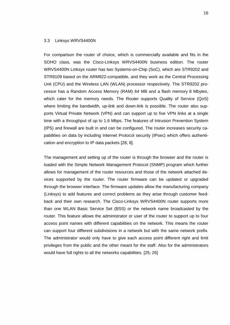
3.3 Linksys WRVS4400N
For comparison the router of choice, which is commercially available and fits in the
SOHO class, was the Cisco-Linksys WRVS4400N business edition. The router
WRVS4400N Linksys router has two Systems-on-Chip (SoC), which are STR9202 and
STR9109 based on the ARM922-compatible, and they work as the Central Processing
Unit (CPU) and the Wireless LAN (WLAN) processor respectively. The STR9202 pro-
cessor has a Random Access Memory (RAM) 64 MB and a flash memory 8 Mbytes,
which cater for the memory needs. The Router supports Quality of Service (QoS)
where limiting the bandwidth, up-link and down-link is possible. The router also sup-
ports Virtual Private Network (VPN) and can support up to five VPN links at a single
time with a throughput of up to 1.6 Mbps. The features of Intrusion Prevention System
(IPS) and firewall are built in and can be configured. The router increases security ca-
pabilities on data by including Internet Protocol security (IPsec) which offers authenti-
cation and encryption to IP data packets [28, 8].
The management and setting up of the router is through the browser and the router is
loaded with the Simple Network Management Protocol (SNMP) program which further
allows for management of the router resources and those of the network attached de-
vices supported by the router. The router firmware can be updated or upgraded
through the browser interface. The firmware updates allow the manufacturing company
(Linksys) to add features and correct problems as they arise through customer feed-
back and their own research. The Cisco-Linksys WRVS4400N router supports more
than one WLAN Basic Service Set (BSS) or the network name broadcasted by the
router. This feature allows the administrator or user of the router to support up to four
access point names with different capabilities on the network. This means the router
can support four different subdivisions in a network but with the same network prefix.
The administrator would only have to give each access point different right and limit
privileges from the public and the other meant for the staff. Also for the administrators
would have full rights to all the networks capabilities. [25; 26]

17
3.4 Ethernet over USB Adapter
The Ethernet over Universal Serial Bus (USB) adapter is an Ethernet gadget that im-
plements the USB port to an Ethernet network. The Ethernet over USB adapter has a
male USB connector on one end and on the other an RJ45 female connector. The
adapter couples the host (dreamplug) with an attached peripheral device which could
be a hub or computer or another router. The Ethernet over USB adapter has two Light
Emitting Diodes (LED) that show the status or speeds that the device is working at. The
Link is for showing if it is ON/OFF and default speeds of 10 Mbps and 100 Mbps re-
spectively. The second LED labeled 1000 Mbps is for showing exactly when data
speeds are in the gigabits per second range. The adapter also spots two Random Ac-
cess Memory (RAM) buffers of 20 Kbytes on either side of transmission, that is, on
both receiving (RX) and transmitting (TX) sides respectively. The buffers are used as
storage space during transmission of data; these buffers increase the throughput of the
Ethernet over USB adapter.
The dreamplug comes with two Universal Serial Bus (USB) ports which can be adapted
to an Ethernet network port. When the adapter is first plugged into a USB port, it is de-
tected by the host system that is the dreamplug. The Linux OS loads a device driver
which will ensure that the installation of the Ethernet over USB adapter is successful
and functions well with the rest of the system. The use of USB port as an Ethernet net-
work interface is possible because the Ethernet v2 transport frames (802.3) have a
Maximum Transmission Unit (MTU) length of 1500 bytes. The Ethernet data frames are
independent of the transport media type in that the data frames can be sliced to fit the
transport media type. The maximum data frames of USB 1.1 are 64 bytes large; hence
a 1500-byte Ethernet frame would be divided 23 times while data packets of USB 2.0
are 512 bytes would be divided 3 times for them to be transmitted in the respective
media. The USB 2.0 has been improved to cover speeds of up to 480 Mbps. [16]

18
4 Software
As stated in the introduction, all of the software in this project was under the open
source banner, meaning they could be altered to fit the job description needed for them
without breaching software rights of a person or organization.
The software in use are:
Linux OS as a Network Operating System (NOS)
Bird Internet Routing Daemon (BIRD)
Webmin (Management System)
Music Player Daemon (MPD).
4.1 Linux as a Network Operating System (NOS)
Networking Operating System (NOS) is a dialoguer or server which provides file, task
and job management. A server in a Local Area Network (LAN) manages resources
such as data, users, groups, security applications and other functions of computers in
the network. The main purpose of Linux as a NOS is to provide resource division to the
connected computers. The dreamplug envisioned use is to act as a webserver, media
server, Wi-Fi access point, or online security server, among many other uses. All the
above applications affect the type of architecture that can be used. [21]
The Linux Kernel is monolithic, meaning the working of all processes are within the
Kernel space. This means the Linux Kernel is the supervisor to the resources available,
including memory management and concurrency. Concurrency is two processes ac-
cessing same resource; this can be achieved by time sharing and/or synchronization of
adjacent processes. For concurrency to be achieved the sharing of resources is para-
mount, where data exchange, memory allocation and execution of scheduling is essen-
tial to minimizing response time and maximizing throughput. The Linux Kernel is best
suited for this type of SOHO devices. Linux Kernel, besides supporting the TCP/IP
stack, also has the major network services that make it ideal. [29, 7]
19
4.2 Bird Internet Routing Daemon
The routing in the Linux operating system is mostly done by the Kernel and the utilities
under iproute2 are adequate for controlling both IPv4 and IPv6. Though for routing pro-
tocols the dreamplug Linux OS needs assistance in creating the routing table. This is
the purpose of adding BIRD to handle all dynamic protocols together with the static
ones; the relevant dynamic routing protocols in SOHO type of routers are namely BGP,
OSPFv2 and OSPFv3, and RIPv2. The OSPFv2 routing protocol handles IPv4 and
OSPFv3 handles IPv6. BIRD routing daemon is a program that supports multiple rout-
ing tables and each routing protocol imports network routes from neighboring routers to
their respective routing tables. The BIRD routing imports create an internal routing ta-
ble which is sent to the Kernel which does decision making and final forwarding of
packets. The routing protocols show how the routers communicate between each oth-
er, meaning the routing protocols are just routing algorithms that prioritize the routes
and give them metric calculations, thus knowing which routes are selected as default.
The bird daemon can be accessed and configured through its configuration table found
in the location "/etc/bird.conf". The configuration file shows that one can config-
ure the bird daemon to synchronize the internal table with that of the Kernel. The bird
daemon can also be configured to advertise among the various networks attached to
the dreamplug router. The configuration that runs in the dreamplug can be viewed in
the appendix 1. [22]

20
4.3 Webmin
The dreamplug computer has a Linux operating system installed in it. The only way to
configure the dreamplug is through the terminal. A part of the project was to make the
dreamplug accessible to a Linux novice user who is not experienced. The Webmin is a
server which manages the Linux system processes. The Webmin User Interface (UI) is
accessed by a browser which enables one to configure the parameters of a particular
program without a need to go to the terminal. Webmin when installed taps to the con-
figuration files of the programs installed in the dreamplug. The administrator or ‘root’
has the privilege to configure or edit the configuration files and so does the Webmin.
The Webmin allows creating and deleting of users, groups, and programs without alter-
ing the program stability in the Linux system. This is because the Webmin is a modular
program where each function can be installed and removed as a module without affect-
ing the other installations. Thus Webmin can be stated to be a configuration tool be-
cause on its own it does not do anything else. There have to be applications and mod-
ules to configure in the host system. The default programs and utilities in the
UNIX/Linux system can be configured through it. The major configurations possible are
under users, group rights and passwords, configuring the network, Domain Name Sys-
tem (DNS), Network File System (NFS), servers, namely Apache, and MySQL, among
other programs. [24]
Besides making administration of application and servers easier to edit, Webmin en-
sures safe alteration of configuration files of various applications. The Webmin notifies
the user any time he/she is about to cause a system-wide problem through, wrongful
deletion of a module or inclusion of wrong configuration data. Webmin can be found in
repositories of most mainstream UNIX/Linux OS versions, though, if that is not the
case, Webmin can be downloaded from the Webmin site. In this case, Webmin was
downloaded, uncompressed, and installed in the dreamplug. The Webmin default port
was configured, which the user could use to access it from the browser and unneces-
sary programs removed. [24]

21
4.4 Sound Module
The Music Player Daemon is a server, music player that uses a client/server model and
the installation uses a few system resources in terms of memory. The MPD can be
accessed by various client side applications either over the local area network or over a
remote network where one configures the accessing port. The default port is 6600. The
dreamplug does not support video output, thus once programmed it can run without a
screen, which is termed as headless. The MPD is quite useful in that it can be pro-
grammed to run when the dreamplug is booted on startup and hence does not require
any administration. This ensures that what is programmed will run even after an inter-
rupt of electricity or any other form of disruption. This project used the MPD to test that
the dreamplug could allow commands over the network, support and play music file
saved in the internal memory. [22]

22
5 International Intensive Program (IP DOSSEE)
The Intensive Program in Developing Open Source Software Expertise in Europe (IP-
DOSSEE) helps to foster cooperation of Higher Education Institutions (HEIs) across
the European Union (EU). It encourages HEIs in the Information Technology (IT) envi-
ronment to research projects selected by the various institutions on varied topics, not
limited to the curriculum. The common factor in the projects is that “open source” is
highly encouraged and wholly used, thus meaning that any project presented by the
various universities use open source applications or ‘source code’. The other part of
the IP-DOSSEE topics is that the projects try solving a communal problem or find an
alternate choice to a commercial product using open source software which is readily
available. [29]
The Austrian chapter of IP-DOSSEE was the final of the three previously held which
were under the stewardship of Helsinki Metropolia University of Applied Sciences. The
participating universities would select a topic and find a team of students favourably in
their third and fourth year of studies in various fields of studies. The team of students
met the lecturers and were presented with a topic which they would discuss and pre-
sent how to handle the problem and result they would expected. The team then drew
specification and requirements document which they deemed would best lead to a fa-
vourable solution. The team went ahead and implemented some of the specifications
got from their research. The project was divided into three; one team looked at the rout-
ing protocols and the routing software, and other team on how to change operating
system of the dreamplug and lastly one team on additional services which could be
included in the router. This was in line with the requirements of the IP DOSSEE docu-
ment on the requirements for the Embedded Linux Router. The result from the home
campus was a technical plan which was partially implemented to clarify soundness of
the results. The technical plan could be found in appendix 2 of this document.
The next phase was going to Austria and having the technical plan implemented by an
international team which were chosen from the other universities participating in the IP-
DOSSEE meet. The team ‘D-Dream’ as was known, was formed from participants from
five different universities and six different nationalities. This could be confirmed by the
picture of the teams from the IP-DOSSEE site [31]. The name was coined from the
idea that the dreamplug computer would give hobbyist and developers a way to dream
and develop new use of embedded systems.

23
The Helsinki Metropolia team selected two project leaders to represent the university
topic to the international team. The team leaders were to present the goals and objec-
tives of their universities’ projects while discussing the technical plan that was drawn in
the local universities with their assigned international teammates. As the team leader of
Helsinki Metropolia before leaving for Austria I contacted my other international team
members through Skype before time, so as to familiarize ourselves with each other and
what skill sets each of us brought to that table. This knowledge of each person’s edu-
cation background gave an idea of where to place each member and how to approach,
and how to go about discussing what is meant to be done in the project. The communi-
cation included sharing the technical plan with them ensuring they had an idea of what
our team was required to do on arrival in Austria.
On arrival to Austria introductions and each person’s knowledge of Linux and network-
ing were carried out first to facilitate the team leaders to introduce the topic and to
know how well to train the members on the need to know the materials, so that the pro-
ject could be carried out successfully. For some it was a new field of study but they
were willing to learn. Hence I and my co-team leader started a small tutorial on the ba-
sics of using the terminal to configure the dreamplug. I allocated to the persons familiar
with Linux and networking a subject to start studying. The parts that were supposed to
be further read on were the web user interface, quality of service (QoS), and the best
testing topology and testing tools.
The other part of the Austrian experience worth mentioning was the planning of the day
to day affairs and the challenges we faced as project managers. At the start of the
week as project managers we had to assess each of our teammate’s knowledge base
and know who to train them further so as to understand the project. This helped when
we were to have discussions, ensuring they could participate in them. Also, the as-
sessment of each one understanding of the topic of choice, that is, networking ensured
we knew where to place each individual in the division of the work-load. The other ma-
jor challenge was the language barrier since for most of them English was a second
language. This fact made the fluent team members to take time explaining concepts
out, and at extreme points we requested assistants from the teachers of the respective
institutions.

24
The other notable challenge during the implementation was that one of the team mem-
bers found that a specific QoS algorithm that would best work was not supported by the
Linux Kernel we were using. This ended up in re-compiling the Kernel just for the sake
of researching if it would work and if it were better. Though the compiled Kernel was
never used it was educational and good to see the team work and the different skill
sets compel each other. After successfully implementing the project, we needed to
make it interesting during the presentation, thus we installed Music Player Daemon
which is a music server which could be accessed and controlled externally. We loaded
music in the dreamplug internal memory and accessed it over the network and played
the music just to show the possibilities that the dreamplug offered.
The IP-DOSSEE program in Austria was an eye opener and brought out the leadership
skills and team building experience which gives one the insight of a working life one
would appreciate. The IP-DOSSEE program showed that working with international
individuals is possible even with language barrier, that is, technology cuts all barriers
and boundaries. This is to point out that Google translate was used during conversa-
tions, where word pronunciation were a problem. The project and the program was a
success in creating new friends and imparting knowledge of how a working environ-
ment should look like. The presentation was well delivered and with all that took place I
could say it was a success. The process lived to the billing of IP-DOSSEE. Universities
come together with the idea of solving communal problems with open source technolo-
gy and in the meanwhile breaking the barriers of country and language as Europeans
and fostering cooperation among all countries and cultures available. [31]

25
6 Testing
The dreamplug is a plug computer and as all computers it ships with an embedded
Linux operating system of Debian distribution as the default OS. In this project Ubuntu
distribution was favoured because although both Debian and Ubuntu are free and open
source, the Ubuntu distributions repositories are maintained by an organisation and are
kept updated and most of the programs are ported for Ubuntu and would be found in
the Ubuntu’s repositories. The steps to changing the operating system from Debian to
Ubuntu can be found in appendix 2 and the steps can be replicated for other operating
system working with an ARM processor on the SheevaPlug platform [32]. However
before the switching of the operating system can be carried out, the downloaded files
have to be moved to the SD card, and then to the dreamplug. Firstly, the SD card was
formatted into two partitions, one that is 100 MB in size and of the file format ‘fat16’,
and the second that is greater than 2 GB of file format ‘ext3’. The file partitions were
named “dp_Kernel” and “dp_ubuntu” which hold the Linux Kernel and the Ubuntu file
system respectively. The best program for this partitioning and formatting is ‘gparted’
which is found in a computer running Linux operating system.
Once the dreamplug operating system was changed to Ubuntu, the sources list of links
was updated and the dreamplug connected to the Internet and the update command
“apt-get update” given. The Linux Kernel updated automatically and the programs had
any changes awaiting in the Ubuntu repositories. The next phase was to install the
drivers for the Joint Test Action Group (JTAG) module to the computer being used to
access the dreamplug during configurations. The JTAG is a standard test access port
and boundary-scan which is used for testing and facilitating debugging of printed board
devices. The JTAG offers the developer way to access the dreamplugs’ boot loader/u-
boot when making changes in the Kernel environment and the boot loader/u-boot envi-
ronment. The JTAG ensures that the developer is not locked out of the device once a
change happens and a restart is required. The developer will still be able to access the
dreamplug internals and error log files and make changes if the situation calls for it.
Once the driver is installed and the hardware interface (COM) port is set, then one can
access the dreamplug with either ‘putty’ or ‘terminal’ application for Windows NT as
well as for a Linux-operated computer. For the Linux-operated computer one could
always run the following line on the ‘konsole’ or ‘xterm’ terminal to access the COM
interface: #screen /dev/ttyUSB0 115200.
26
This opens a screen with a baud rate of 115200 or symbols/second. The baud rate is
digital pulse rate needed to make the information on the dreamplug visible on the
screen. Once this setup is complete, one is ready to start running the test on the
dreamplug.
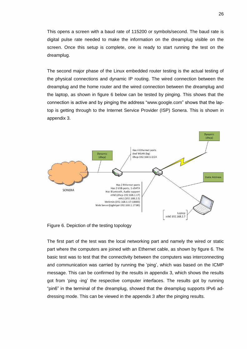
The second major phase of the Linux embedded router testing is the actual testing of
the physical connections and dynamic IP routing. The wired connection between the
dreamplug and the home router and the wired connection between the dreamplug and
the laptop, as shown in figure 6 below can be tested by pinging. This shows that the
connection is active and by pinging the address “www.google.com” shows that the lap-
top is getting through to the Internet Service Provider (ISP) Sonera. This is shown in
appendix 3.
Figure 6. Depiction of the testing topology
The first part of the test was the local networking part and namely the wired or static
part where the computers are joined with an Ethernet cable, as shown by figure 6. The
basic test was to test that the connectivity between the computers was interconnecting
and communication was carried by running the ‘ping’, which was based on the ICMP
message. This can be confirmed by the results in appendix 3, which shows the results
got from ‘ping -ing’ the respective computer interfaces. The results got by running
“pin6” in the terminal of the dreamplug, showed that the dreamplug supports IPv6 ad-
dressing mode. This can be viewed in the appendix 3 after the pinging results.

27
The third phase of testing was the wireless LAN which uses Dynamic Host Configura-
tion Protocol (DHCP), so as to allow network devices to connect to the router and
communicate on the IP network (Internet). The issuing of IP addresses is done dynam-
ically from a pool of addresses. The dreamplug has a small DHCP server whose con-
figuration file is under the file address “/etc/udhcp.conf”. This file shows the pool of ad-
dresses that can be issued dynamically and the maximum lease time in seconds and
the lease file that stores the mac addresses of the devices connected. All this infor-
mation we can access through the use of the utility “uaputl” which is a driver enabling
the dreamplug to be a Wi-Fi access point. The files that ensure that the wireless LAN
operates can be found in appendix 4.
The Installation and configuration of the ‘BIRD’ routing software was carried out with-
out a hitch, although as a drawback the bird command line utility “birdc” does not seem
to run. When ran, it gives an error as listed below:
root@dreamplug2:~# birdc
Unable to connect to server control socket
(/var/run/bird.ctl): No such file or directory
This shows that during installation the process never installed the user command line
interface, only the server side. Despite the drawback, the bird routing software could be
confirmed working through system log files. The listing below shows system log files
under “/var/log/syslog” displaying the activity of the bird server:
Nov 29 17:47:37 dreamplug2 bird: device1: Scanning interfac-
es
Nov 29 17:47:37 dreamplug2 bird: Kernel1: Scanning routing
table
Nov 29 17:47:37 dreamplug2 bird: Kernel1: Pruning table mas-
ter
Nov 29 17:47:44 dreamplug2 bird: MyOSPF: HELLO packet sent
via eth0
Nov 29 17:47:44 dreamplug2 bird: MyOSPF: HELLO packet sent
via eth1
Listing 1. Bird routing activity log
28
As per the captured data in listing 1 above, it shows the bird routing software in con-
junction with the Kernel working together to update the routing table. The bird routing
software runs the instance of OSPF protocol ‘MyOSPF’ which scans all Ethernet inter-
faces (eth*) and populates the routing table. The Kernel scans the routing table and
makes changes to the main routing table as shown under the captured data under
(Kernel1), which it uses to forward packets to the other networks. The results above
covered the control plane and the data plane of the dreamplug router. The status of the
dreamplug router can be confirmed by use of network statistics (netstat) which, when
run with various options, give the output of active Internet and socket connections of
servers and their state and Process ID (pid) numbers. The printout can be viewed in
appendix 5.
The ‘iperf’ is a tool for measuring the bandwidth of a link and the throughput of a device
doing the routing of packets. The tool ‘iperf’ works in the form of a client/server archi-
tecture setup where one computer runs the client-side part of software while the other
runs the server side. The server listens to the port 5001 and from the client side a script
is ran sending packets to the specific address of the computer running server-side. For
the throughput to be stable and show the correct value, it has to go through the routing
section of the router. Thus in most routers connection goes through LAN and WAN
ports of the router. In the case of the dreamplug there are two Ethernet ports, which
could both be used as either/or LAN and/or WAN. The test for throughput is tested
across the Ethernet cable since the wireless is not stable for the test and hence it is not
advisable to use the wireless part to run the throughput test. The other reason is that
the speed of the Ethernet is faster on the Ethernet cable than on the Wi-Fi for there are
no disruptions.
The first test of ‘iperf’ carried out was measurement for bandwidth between the laptop
and a desktop computer connected to the home router, as shown in figure 6 above.
The Ethernet cable is the only cable connecting the laptop to the Internet and through
the dreamplug. Hence routing takes place. The results are as shown in appendix 5
IPERF section. Also the test showed that the change in the TCP window size did not
do anything to alter the bandwidth of the dreamplug. The test for checking if the band-
width of two TCP streams running at the same time add up to the value of the total
bandwidth was a success, as seen in the results in appendix 5.

29
The next phase was to ensure both the administrator and user could access an easier
way to configure the dreamplug and install applications. For the management applica-
tion the Webmin was chosen for it supports the dreamplug and it is easier to use, as
explained in section 4.2.
The Webmin brings the graphic user interface to the dreamplug and offers more in
terms of accessing the daemon and configuration files, which ensure the user can alter
the working of specific programs installed in the dreamplug system. The Webmin also
offers the ability to install new daemons or programs which are supported by the
Webmin platform. Developers can develop or program software for the Webmin plat-
form for it is open source and allows for third party drivers or daemons which have
been ported for the platform. The open platform APIs of Webmin increases the flexibil-
ity of using Webmin as most programs found in Linux distributions have been ported
under the Webmin. The applications found in the Ubuntu repositories for Webmin are
not available for the dreamplug repositories because they are stripped down to the
bare minimum. Thus installation is done manually as shown consecutively on the
Webmin site. Once the Webmin is downloaded and installed, the user could access the
dreamplug using a browser with the IP address assigned by the ISP or home router.
The address on my browser was as follows: https://192.168.1.17:10000/
The Webmin source list ‘links’ could be added to the file “/etc/apt/sources.list” to ensure
that when updating the dreamplug automatically by running “apt-get update” the
Webmin would be updated too. Although for this to be accepted, the user must run the
GNU Privacy Guard key to sign the software as authentic. This GNU privacy key allows
update from the developers’ database allow the Webmin program installed to access
them.

30
The pictures captured in the screen of the computer, figure 7 and appendix 6, show
that the Webmin was successfully installed and it works. To log in one uses the default
username/password “root/nosoup4u”. When the user logs in, the page visible is that of
the status of the dreamplug internals which is; the dreamplugs’ OS type, the version of
the Webmin, the processes running, and the memory remaining. On the left of the
screen there is a menu giving breakdown of classifications of programs available. The
un-collapsed tab shows further divisions under the others part. Once the part is select-
ed from the OtherFile Manager the service runs a Java certificate which needs ap-
proval since it is not identified by the browser and my computer. The file manger tab
when selected opens a Graphical User Interface where the file system root folders are
on the left and when selected, the internal files and folders are viewed on the right
pane window. The left part of the navigation pane only shows folders and not the files
under it. Above the navigation pane and the main selection window there is a menu bar
which has an easier way of carrying out functions such as creating folders and editing
files. When a file is selected to be edited, it opens a window with all tools for available
for searching and saving purposes among others the changes is possible, as shown by
the captured by figure 7 and figure 8 below.
Figure 7. Webmin security certificate

31
The screen shot below shows the File manager navigtion pane and the selected folder
open on the right side of the window.
Figure 8. Webmin File manager
32
7 Conclusion
The project was aimed to show the capability of a dreamplug as a router developed
with free open source developed programs so that it could still compete equally with
commercially available embedded routers found in shops. The services that are offered
by the dreamplug give an added advantage to the dreamplug as a router and a com-
puter. The Webmin besides giving the user flexibility to customization for the router,
offers more modules and drivers including third party programs. This is in the sense
that the user can update the Linux Kernel or any other application, so as to remain cur-
rent. This means that the router keeps offering even newer features and services every
time a new feature comes out and there would be no cost.
The project can be further developed to include network-attached storage, cloud ser-
vices where one uses the router to access a headless server. Due to applications such
as samba one can keep the files in their respective laptops synchronised with the
online server the moment one is in the home network environment. The presence of
the audio module in the router shows the ability to use it for Voice over IP (VoIP) calls.
The part of using the router as a media server was explored by the use of installing an
MPD music server which enables one to access the music in the router over the net-
work.
The project could further integrate the Bluetooth modem so that near field communica-
tion (NFC) can be used to do transaction where authentication of the user is required.
For example in an Internet café a user could register an account and once close
enough, and then he/she is allowed to use the Wi-Fi automatically. Further develop-
ment needs to be done for the drivers for ‘usbnet’ to accept the Kernel being by the
dreamplug. This would aid the number of computers that can be supported by the
dreamplug at any particular moment. The project can be stated to be as a success and
the dreamplug is in no way inferior to commercial routers for the Small Office Home
Office category. Further projects could be based on it since it does not show limitation
in scalability.

33
References
1. Cisco: What is a Network Switch vs. a Router? [Online]
URL:http://www.cisco.com/cisco/web/solutions/small_business/resource_center/arti
cles/connect_employees_and_offices/what_is_a_network_switch/index.html Ac-
cessed 11 April 2012.
2. kratky J. Cisco: Internetworking Technology Handbook [Online]. Updated on 10th
April 2012.
URL:http://docwiki.cisco.com/wiki/Internetworking_Technology_Handbook#Routing.
Accessed 12 April 2012.
3. Malhotra R. IP Routing. United States of America: O’Reilly & Associates Inc, CA;
2002.
4. Webopedia [Online]
URL:http://www.webopedia.com/TERM/R/router.html. Accessed 12 April 2012.
5. Software Information Center[Online]
URL:http://publib.boulder.ibm.com/infocenter/cicsts/v3r1/index.jsp?topic=%2Fcom.i
bm.cics.ts31.doc%2Fdfhtm%2Fdfhtm32.htm Accessed 13 April 2012.
6. Exist E, Baker F. Requirements for IP Version 4 Routers [online]. Network Working
Group. Edited June 1995
URL: http://tools.ietf.org/html/rfc1812#section-2.2.3. Accessed 12 April 2012.
7. Webopedia [online]
URL:http://www.webopedia.com/TERM/P/protocol.html. Accessed 23rd April 2012.
8. Hall Eric. Internet Core Protocols: The Definitive Guide: O’reilly Media [online]. Print
February 2000. Ebook June 2009.
URL:http://oreilly.com/catalog/coreprot/chapter/appb.html. Accessed 23 April 2012.
9. Exist E, Kent S, Seo K. Security Architecture for the Internet Protocol [online]. In-
ternet Engineering Task Force (IETF); December 2005.
URL: http://tools.ietf.org/html/rfc4301#page-4. Accessed 24 April 2012.
10. Ramakrishnan K, Floyd S, Black D. Explicit Congestion Notification (ECN) to IP
[online]. September 2001.
URL: http://www.ietf.org/rfc/rfc3168.txt. Accessed 25 April 2012.
34
11. Holbrook H, Cain B, Haberman B. Using Internet Group Management Protocol Ver-
sion 3 (IGMPv3) and Multicast Listener Discovery Protocol Version 2 (MLDv2) for
Source-Specific Multicast. August 2006.
URL: http://tools.ietf.org/html/rfc4604. Accessed 25 April 2012.
12. Martin A. Brown. Guide to IP Layer Network Administration with Linux [Online].
March 2007.
URL: http://linux-ip.net/html/routing-tables.html. Accessed 30 April 2012.
13. Malkin G. RIP Version 2. November 1998.
URL: http://www.faqs.org/rfcs/rfc2453.html#b. Accessed 9 May 2012.
14. Moy J. OSPF version 2. April 1998.
URL: http://www.faqs.org/rfcs/rfc2328.html#b. Accessed 9 May 2012.
15. Globalscale Technologies. DreamPlug-DevKit. Globalscale Technologies Inc. 1200
N. Van Buren Street, Unit #D Anaheim, CA 92807 U.S.A.
URL: http://www.globalscaletechnologies.com/p-54-dreamplug-devkit.aspx. Ac-
cessed 21 May 2012.
16. Petazzoni T, Opdenacker M. Bootloaders: Free Electrons. Updated Jan 19,2011
URL: http://free-electrons.com/docs/bootloaders/. Accessed June 4, 2012.
17. Opdenacker Michael. Linux USB drivers: Free Electrons. Updated Sep 15,2009
URL: http://free-electrons.com/doc/linux-usb.pdf. Accessed 4 August 2012.
18. Cameron Jamie. Managing Linux Systems with Webmin [Online]. States of Ameri-
ca: Pearson Education Inc, NJ; 2004.
19. Exist Errata, etc. Internet Protocol. Updated September 1981
URL: http://tools.ietf.org/html/rfc791#section-3.1. Accessed 27 August 2012.
20. Exist E and Postel J. Internet Control Message Protocol. Network Working Group;
September 1981.
URL: http://tools.ietf.org/html/rfc792. Accessed 27 August 2012.
21. Nguyen Binh. Linux Dictionary. 16th August 2004
URL: http://www.tldp.org/LDP/Linux-Dictionary/html/index.html. Accessed 20th Oc-
tober 2012.
22. Jonathan Roberts. MPD: Personal sound server. Linux Format [magazine] Issue
149 October 2011. Accessed 15th October 2012.
23. Fallip O, Machek P, Mares M, Zajicek O. BIRD Internet Routing Daemon [Online].
Updated 2nd April 2012.
URL: http://bird.network.cz/?get_doc&f=bird.html . Accessed 20th October 2012.
24. Jamie Cameron. Managing Linux Systems with Webmin: System Administrationand
Module Development. Upper Saddle River , NJ: Prentice Hall; 2004.
35
25. Cisco. Administration Guide: WRVS4400N Wireless-N Gigabit Security Router with
VPN.
URL:http://www.cisco.com/en/US/docs/routers/csbr/wrvs4400n/administration/guide
/WRVS4400N_AG_OL-20048.pdf. Accessed 25th October 2012.
26. Linksys. Linksys WRVS4400N v1.0. Modified 1 May 2012.
URL: http://www.wikidevi.com/wiki/Linksys_WRVS4400N_v1.0. Accessed 25th Oc-
tober 2012.
27. Marvell. Marvell 88F6281 SoC with Sheeva Technology. Marvell Semiconductor,
Inc. 5488 Marvell Lane, CA 95054.
URL: www.marvell.com
28. Exist E, Kent S, Seo K. Security Architecture for the Internet Protocol. December
2005.
URL: http://tools.ietf.org/html/rfc4301#page-4. Accessed 5 November 2012.
29. Love Robert. Linux Kernel Development Third Edition. Upper Saddle River, NJ.
Pearson Education, Inc.; 2010.
30. Kagechu P, Nylund T, Schuster R, Haidinger K, Montero V, Svec J, Barkovskis V,
Demics G. Developing Open Source Software Expertise in Europe. March 2012.
URL:https://ip-wiki.metropolia.fi/dossee2012/index.php/Main_Page. Accessed 5
November 2012.
31. Patrick K, Tuomas N, etc. D-Dream: IP DOSSEE. March 2012.
URL:https://ip-wiki.metropolia.fi/dossee2012/index.php/Team_7:_D-
Dream#Webmin_2. Accessed 6 November 2012.
32. “Yuchouc…@gmail.com”. 17 June 2011
URL:http://dreamplug.googlecode.com/files/Dreamplug%20-
%20Change%20OS%20from%20%20Debian%20to%20Ubuntu-20110615.1.pdf
Accessed March 2012.
33. Exist E, Kent S, Seo K. Security Architecture for the Internet Protocol [online]. Edit-
ed December 2005.
URL: http://tools.ietf.org/html/rfc4301. Accessed 26 November 2012.

Appendix 1
1 (4)
Appendix 1. BIRD Configuration file
/* * This is an example configuration file. */ # Yes, even shell-like comments work... # Configure logging #log syslog { debug, trace, info, remote, warning, error, auth, fatal, bug }; #log stderr all; #log "tmp" all; # Override router ID #router id 62.168.0.1; # You can define your own symbols... #define xyzzy = 120+10; # Define a route filter... filter test_filter { if net ~ 10.0.0.0/16 then accept; else reject; } #filter sink { reject; } #filter okay { accept; } # Define another routing table #table testable; # Turn on global debugging of all protocols #debug protocols all; # The direct protocol automatically generates device routes to # all network interfaces. Can exist in as many instances as you wish # if you want to populate multiple routing tables with device routes. protocol direct { # interface "-eth*", "*"; # Restrict network interfaces it works with } # This pseudo-protocol watches all interface up/down events. protocol device { scan time 10; # Scan interfaces every 10 seconds } # Static routes (again, there can be multiple instances, so that you # can disable/enable various groups of static routes on the fly). protocol static { # disabled; # Disable by default # table testable; # Connect to a non-default table # preference 1000; # Default preference of routes

Appendix 1
2 (4)
# debug { states, routes, filters, interfaces, events, packets }; # debug all; # route 0.0.0.0/0 via 62.168.0.13; # route 62.168.0.0/25 reject; # route 10.0.0.0/8 reject; # route 10.1.1.0:255.255.255.0 via 62.168.0.3; # route 10.1.2.0:255.255.255.0 via 62.168.0.3; # route 10.1.3.0:255.255.255.0 via 62.168.0.4; # route 10.2.0.0/24 via "arc0"; } This part supports the RIP protocol: # RIP aka Rest In Pieces... #protocol rip MyRIP { # You can also use an explicit name # preference xyzzy; # debug all; # port 1520; # period 7; # infinity 16; # garbage time 60; # interface "*" { mode broadcast; }; # honor neighbor; # To whom do we agree to send the routing table # honor always; # honor never; # passwords { password "ahoj" from 0 to 10; # password "nazdar" from 10; # } # authentication none; # import filter { print "importing"; accept; }; # export filter { print "exporting"; accept; }; #} This part supports the OSPF protocol: protocol ospf MyOSPF { tick 2; # rfc1583compat yes; area 0.0.0.0 { stub no; interface "eth*" { hello 10; retransmit 6; cost 10; transmit delay 5; dead count 4; wait 10; type broadcast; authentication none; # password "pass"; }; # interface "arc0" { # rx buffer large;

Appendix 1
3 (4)
# type nonbroadcast; # poll 14; # dead 75; # neighbors { # 10.1.1.2 eligible; # 10.1.1.4; # }; # strict nonbroadcast yes; # }; # interface "xxx0" { # passwords { # password "abc" { # id 1; # generate to "22-04-2003 11:00:06"; # accept to "17-01-2004 12:01:05"; # }; # password "def" { # id 2; # generate from "22-04-2003 11:00:07"; # accept from "17-01-2003 12:01:05"; # }; # authentication cryptographic; # }; }; # area 20 { # stub 1; # interface "ppp1" { # hello 8; # authentication none; # }; # interface "fr*"; # virtual link 192.168.0.1 { # password "sdsdffsdfg"; # authentication cryptographic; # }; # }; } This is the BGP protocol #protocol bgp { # disabled; # local as 65000; # neighbor 62.168.0.130 as 5588; # multihop 20 via 62.168.0.13; # hold time 240; # startup hold time 240; # connect retry time 120; # keepalive time 80; # defaults to hold time / 3 # start delay time 5; # How long do we wait before initial connect # error wait time 60, 300;# Minimum and maximum time we wait after an error (when consecutive # # errors occur, we increase the delay exponentially ...

Appendix 1
4 (4)
# error forget time 300; # ... until this timeout expires) # disable after error; # Disable the protocol automatically when an error occurs # next hop self; # Disable next hop processing and always advertise our local address as nexthop # path metric 1; # Prefer routes with shorter paths (like Cisco does) # default bgp_med 0; # MED value we use for comparison when none is defined # default bgp_local_pref 0; # The same for local preference # source address 62.168.0.14; # What local address we use for the TCP connec-tion # password "secret" # Password used for MD5 authentication # rr client; # I am a route reflector and the neighor is my client # rr cluster id 1.0.0.1 # Use this value for cluster id instead of my router id # export where source=RTS_STATIC; # export filter { # if source = RTS_STATIC then { ## bgp_community = -empty-; bgp_community = add(bgp_community,(65000,5678)); ## bgp_origin = 0; # bgp_community = -empty-; bgp_community.add((65000,5678)); ## if (65000,5678) ~ bgp_community then ## bgp_community.add((0, 1)); # if bgp_path ~ / 65000 / then # bgp_path.prepend(65000); # accept; # } # reject; # }; #}
Appendix 2
1 (16)
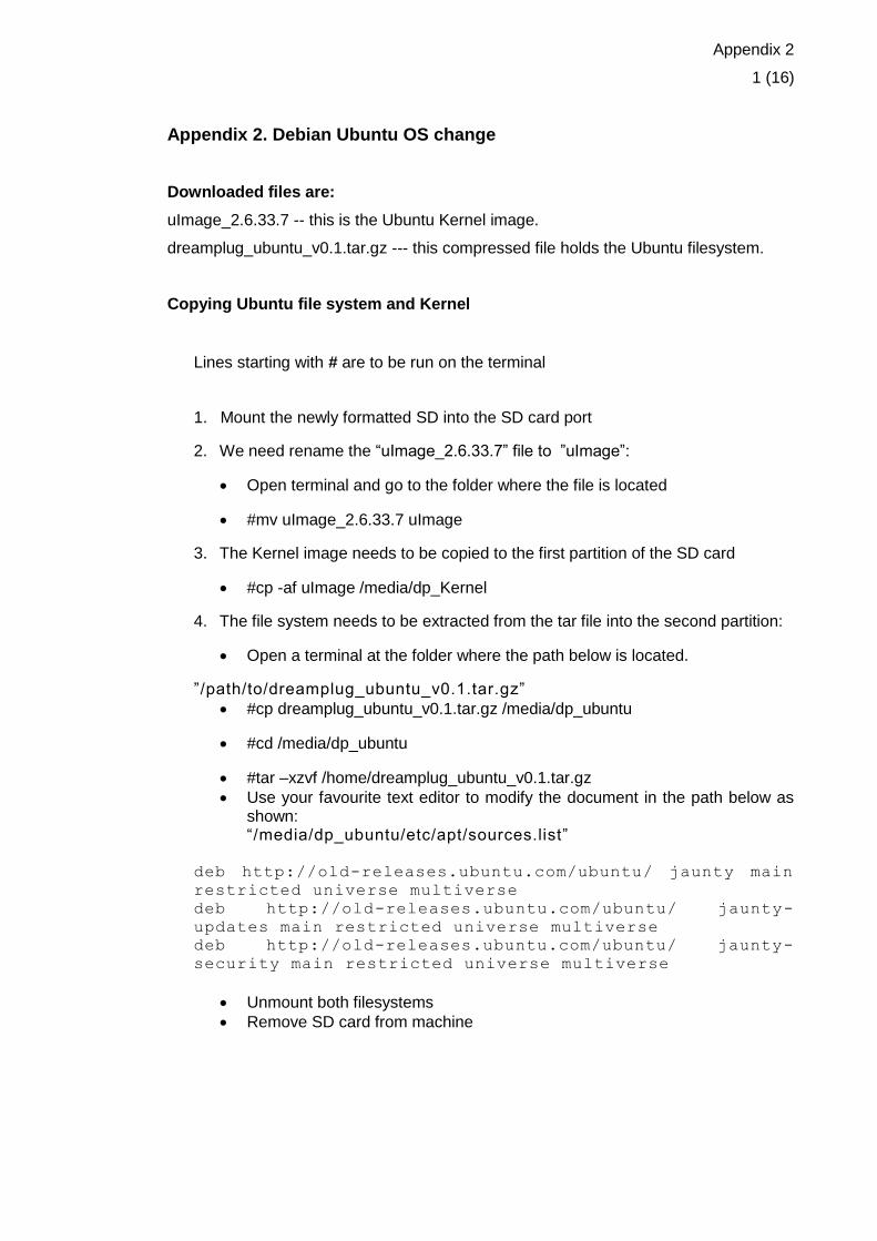
Appendix 2. Debian Ubuntu OS change
Downloaded files are:
uImage_2.6.33.7 -- this is the Ubuntu Kernel image.
dreamplug_ubuntu_v0.1.tar.gz --- this compressed file holds the Ubuntu filesystem.
Copying Ubuntu file system and Kernel
Lines starting with # are to be run on the terminal
1. Mount the newly formatted SD into the SD card port
2. We need rename the “uImage_2.6.33.7” file to ”uImage”:
Open terminal and go to the folder where the file is located
#mv uImage_2.6.33.7 uImage
3. The Kernel image needs to be copied to the first partition of the SD card
#cp -af uImage /media/dp_Kernel
4. The file system needs to be extracted from the tar file into the second partition:
Open a terminal at the folder where the path below is located.
”/path/to/dreamplug_ubuntu_v0.1.tar.gz”
#cp dreamplug_ubuntu_v0.1.tar.gz /media/dp_ubuntu
#cd /media/dp_ubuntu
#tar –xzvf /home/dreamplug_ubuntu_v0.1.tar.gz
Use your favourite text editor to modify the document in the path below as shown: “/media/dp_ubuntu/etc/apt/sources.list”
deb http://old-releases.ubuntu.com/ubuntu/ jaunty main
restricted universe multiverse
deb http://old-releases.ubuntu.com/ubuntu/ jaunty-
updates main restricted universe multiverse
deb http://old-releases.ubuntu.com/ubuntu/ jaunty-
security main restricted universe multiverse
Unmount both filesystems
Remove SD card from machine

Appendix 2
2 (16)
Running Ubuntu on Dreamplug
1. Put the SD card into the Dreamplug.
2. Attach the external JTAG module to the Dreamplug through the UART port.
3. Attach External JTAG module to a computer
4. The device should appear as a serial port. The correct baud rate is 115200
5. Open the serial port
6. Turn on Dreamplug and press a key on the serial port within a couple of
seconds of boot to get to the bootloader:
7. Run these commands on the bootloader:
1. #setenv x_bootargs_root root=/dev/sdc2 rootdelay=10
2. #setenv x_bootcmd_Kernel fatload usb 2 0x6400000 uImage
3. #saveenv
4. #boot
5. This makes the Dreamplug boot from the external SD card
8. Ubuntu should now start booting up
1. username: root
2. password: nosoup4u
9. You are running the linux system

Appendix 2
3 (16)
Appendix 3. Network Testing
This part covers pings and data captures when the test was done on the figure 6 in the
testing chapter.
Static routing
This is the result for pinging the dreamplug router from the laptop as shown in the
figure 6. This shows that there is an established link between the two devices to be
able to pass data between them.
C:\Users\mungai kagechu>ping 192.168.1.17
Pinging 192.168.1.17 with 32 bytes of data:
Reply from 192.168.1.17: bytes=32 time=2ms TTL=64
Reply from 192.168.1.17: bytes=32 time=1ms TTL=64
Reply from 192.168.1.17: bytes=32 time=1ms TTL=64
Reply from 192.168.1.17: bytes=32 time=1ms TTL=64
Ping statistics for 192.168.1.17:
Packets: Sent = 4, Received = 4, Lost = 0 (0% loss),
Approximate round trip times in milli-seconds:
Minimum = 1ms, Maximum = 2ms, Average = 1ms

Appendix 2
4 (16)
This part of test shows that the laptop is getting across to the ISP and is getting
Internet connection to the outside world. This is what the pinging of the address
“www.google.com” shows.
C:\Users\mungai kagechu>ping www.google.com
Pinging www.google.com [74.125.143.105] with 32 bytes of da-
ta:
Reply from 74.125.143.105: bytes=32 time=18ms TTL=45
Reply from 74.125.143.105: bytes=32 time=18ms TTL=45
Reply from 74.125.143.105: bytes=32 time=21ms TTL=45
Reply from 74.125.143.105: bytes=32 time=18ms TTL=45
Ping statistics for 74.125.143.105:
Packets: Sent = 4, Received = 4, Lost = 0 (0% loss),
Approximate round trip times in milli-seconds:
Minimum = 18ms, Maximum = 21ms, Average = 18ms
This part shows the results of “ipconfig” when run in the laptop
Ethernet adapter Local Area Connection:
Connection-specific DNS Suffix . :
Link-local IPv6 Address . . . : fe80::d42c:1621:7f08:4dda%22
IPv4 Address. . . . . . . . . . . : 192.168.2.7
Subnet Mask . . . . . . . . . . . : 255.255.255.0
Default Gateway . . . . . . . . . : 192.168.2.5
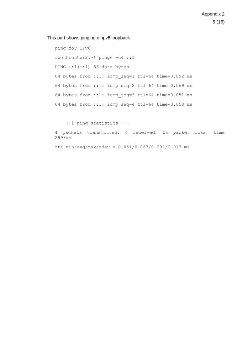
Appendix 2
5 (16)
This part shows pinging of ipv6 loopback
ping for IPv6
root@router2:~# ping6 -c4 ::1
PING ::1(::1) 56 data bytes
64 bytes from ::1: icmp_seq=1 ttl=64 time=0.092 ms
64 bytes from ::1: icmp_seq=2 ttl=64 time=0.069 ms
64 bytes from ::1: icmp_seq=3 ttl=64 time=0.051 ms
64 bytes from ::1: icmp_seq=4 ttl=64 time=0.058 ms
--- ::1 ping statistics ---
4 packets transmitted, 4 received, 0% packet loss, time
2998ms
rtt min/avg/max/mdev = 0.051/0.067/0.092/0.017 ms

Appendix 2
6 (16)
Appendix 4. Wireless LAN Testing
The files that fall under this category are paramount for the proper functioning of the
dreamplug to work as a WiFi Access Point (AP). Firstly we look at the ”udhcp.conf” file
which shows the pool of addresses which are to be issued, the lease time and the file
holding the leased devices mac addresses. Also the file holds the local domain name
and the dns address. All this ensures that the DHCP network protocol works well. The
lease file can be cleared of old mac addresses by removing the file and later replacing
them and their timestamp through the Linux command ”touch”. Once the lease file
timestamp has been updated it is always essential to restart the ’udhcp server’.
root@dreamplug2:~# cat /etc/udhcpd.conf
start 192.168.4.100
end 192.168.4.200
interface uap0
opt lease 86400
opt router 192.168.4.1
opt subnet 255.255.255.0
opt dns 192.168.4.1
opt domain localdomain
max_leases 101
lease_file /var/lib/udhcpd.leases
auto_time 5
root@dreamplug2:~# rm /var/lib/udhcpd.leases
root@dreamplug2:~# rm /var/lib/udhcpd.leases
rm: cannot remove `/var/lib/udhcpd.leases': No such file or
directory
root@dreamplug2:~# touch /var/lib/udhcpd.leases

Appendix 2
7 (16)
root@dreamplug2:~# /etc/init.d/udhcpd restart
Restarting very small DHCP server: udhcpd (v0.9.9-pre) start-
ed
udhcpd.
The information below is from the renew address of the wireless LAN from the laptop
showing its been issued an address fron the udhcp server. And also showing the con-
figuration file of the interfaces and the ping of ”www.google.com” to show that forward-
ing of packest is happening through the dreamplug router.
root@dreamplug2:~# cat /etc/network/interfaces
# Used by ifup(8) and ifdown(8). See the interfaces(5)
manpage or
# /usr/share/doc/ifupdown/examples for more information.
auto lo
iface lo inet loopback
auto eth0 #connected to the home router
iface eth0 inet dhcp
auto eth1 #connected to the laptop ethernet
iface eth1 inet static
address 192.168.2.5
netmask 255.255.255.0
network 192.168.2.0
broadcast 192.168.2.255

Appendix 2
8 (16)
auto uap0 #wireless interface
iface uap0 inet static
address 192.168.4.5
netmask 255.255.255.0
network 192.168.4.0
broadcast 192.168.4.255
ip route add default via 192.168.1.1 dev eth0 #defining
default route
#route add -net 192.168.4.0 netmask 255.255.255.0 gw
192.168.4.1 dev uap0
route add -net 192.168.2.0 netmask 255.255.255.0 gw
192.168.2.1 dev eth1
This is the ”uaputl” utility print out for connected devices:
root@dreamplug2:~# uaputl sta_list
Number of STA = 2
#The first one is the mac address of my phone and the second of the laptop.
STA 1 information:
=====================
MAC Address: 98:0c:82:88:73:29
Power mfg status: power save
Rssi : -41 dBm
STA 2 information:
=====================
MAC Address: 4c:0f:6e:eb:ba:b7
Power mfg status: active
Rssi : -68 dBm
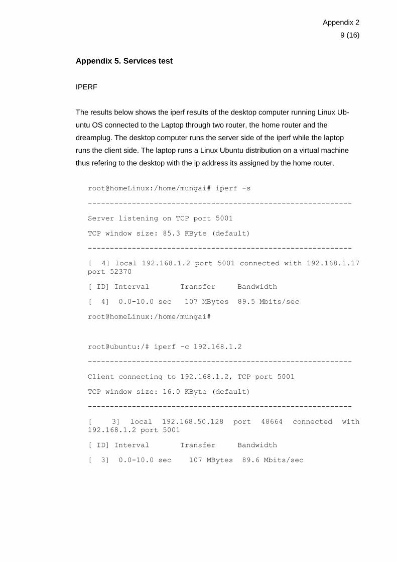
Appendix 2
9 (16)
Appendix 5. Services test
IPERF
The results below shows the iperf results of the desktop computer running Linux Ub-
untu OS connected to the Laptop through two router, the home router and the
dreamplug. The desktop computer runs the server side of the iperf while the laptop
runs the client side. The laptop runs a Linux Ubuntu distribution on a virtual machine
thus refering to the desktop with the ip address its assigned by the home router.
root@homeLinux:/home/mungai# iperf -s
------------------------------------------------------------
Server listening on TCP port 5001
TCP window size: 85.3 KByte (default)
------------------------------------------------------------
[ 4] local 192.168.1.2 port 5001 connected with 192.168.1.17
port 52370
[ ID] Interval Transfer Bandwidth
[ 4] 0.0-10.0 sec 107 MBytes 89.5 Mbits/sec
root@homeLinux:/home/mungai#
root@ubuntu:/# iperf -c 192.168.1.2
------------------------------------------------------------
Client connecting to 192.168.1.2, TCP port 5001
TCP window size: 16.0 KByte (default)
------------------------------------------------------------
[ 3] local 192.168.50.128 port 48664 connected with
192.168.1.2 port 5001
[ ID] Interval Transfer Bandwidth
[ 3] 0.0-10.0 sec 107 MBytes 89.6 Mbits/sec
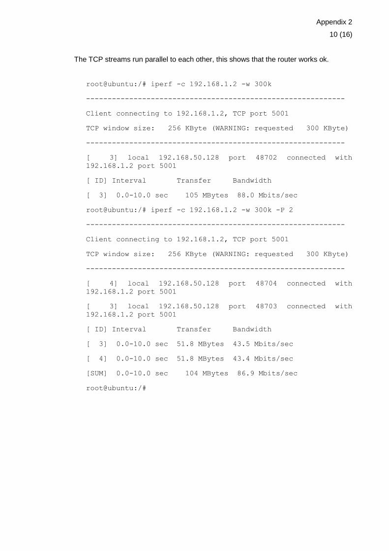
Appendix 2
10 (16)
The TCP streams run parallel to each other, this shows that the router works ok.
root@ubuntu:/# iperf -c 192.168.1.2 -w 300k
------------------------------------------------------------
Client connecting to 192.168.1.2, TCP port 5001
TCP window size: 256 KByte (WARNING: requested 300 KByte)
------------------------------------------------------------
[ 3] local 192.168.50.128 port 48702 connected with
192.168.1.2 port 5001
[ ID] Interval Transfer Bandwidth
[ 3] 0.0-10.0 sec 105 MBytes 88.0 Mbits/sec
root@ubuntu:/# iperf -c 192.168.1.2 -w 300k -P 2
------------------------------------------------------------
Client connecting to 192.168.1.2, TCP port 5001
TCP window size: 256 KByte (WARNING: requested 300 KByte)
------------------------------------------------------------
[ 4] local 192.168.50.128 port 48704 connected with
192.168.1.2 port 5001
[ 3] local 192.168.50.128 port 48703 connected with
192.168.1.2 port 5001
[ ID] Interval Transfer Bandwidth
[ 3] 0.0-10.0 sec 51.8 MBytes 43.5 Mbits/sec
[ 4] 0.0-10.0 sec 51.8 MBytes 43.4 Mbits/sec
[SUM] 0.0-10.0 sec 104 MBytes 86.9 Mbits/sec
root@ubuntu:/#

Appendix 2
11 (16)
Netstat is a network tool used to show the streams that are available and which appli-
cations are using specific ports. It also shows the route that is being used by the router.
root@dreamplug2:~# netstat -le
Active Internet connections (only servers)
Proto Recv-Q Send-Q Local Address Foreign Address
State User Inode
tcp 0 0 *:webmin *:*
LISTEN root 4673
tcp 0 0 *:domain *:*
LISTEN root 3664
tcp 0 0 *:ssh *:*
LISTEN root 3709
tcp 0 0 localhost:ipp *:*
LISTEN root 4325
tcp6 0 0 [::]:www [::]:*
LISTEN root 4465
tcp6 0 0 [::]:domain [::]:*
LISTEN root 3666
tcp6 0 0 [::]:ssh [::]:*
LISTEN root 3711
udp 0 0 *:10000 *:*
root 4674
udp 0 0 *:domain *:*
root 3663
udp 0 0 *:bootpc *:*
root 2661
udp6 0 0 [::]:domain [::]:*
root 3665
Active UNIX domain sockets (only servers)
Proto RefCnt Flags Type State I-Node Path
Unix 2 [ACC] STREAM LISTENING 3632
/var/run/dbus/system_bus_socket
unix 2 [ ACC ] STREAM LISTENING 4252
@/org/bluez/audio
unix 2 [ ACC ] STREAM LISTENING 3749
@/var/run/hald/dbus-ljFm3zE0zZ
unix 2 [ ACC ] STREAM LISTENING 4247
/var/run/sdp
unix 2 [ ACC ] STREAM LISTENING 3758
@/var/run/hald/dbus-YQFrL0Mq5f
unix 2 [ ACC ] STREAM LISTENING 4326
/var/run/cups/cups.sock

Appendix 2
12 (16)
root@dreamplug2:~# netstat -lpn
Active Internet connections (only servers)
Proto Recv-Q Send-Q Local Address Foreign Address
State PID/Program name
tcp 0 0 0.0.0.0:10000 0.0.0.0:*
LISTEN 2504/perl
tcp 0 0 0.0.0.0:53 0.0.0.0:*
LISTEN 2145/dnsmasq
tcp 0 0 0.0.0.0:22 0.0.0.0:*
LISTEN 2163/sshd
tcp 0 0 127.0.0.1:631 0.0.0.0:*
LISTEN 2322/cupsd
tcp6 0 0 :::80 :::*
LISTEN 2404/lighttpd
tcp6 0 0 :::53 :::*
LISTEN 2145/dnsmasq
tcp6 0 0 :::22 :::*
LISTEN 2163/sshd
udp 0 0 0.0.0.0:10000 0.0.0.0:*
2504/perl
udp 0 0 0.0.0.0:53 0.0.0.0:*
2145/dnsmasq
udp 0 0 0.0.0.0:68 0.0.0.0:*
1452/dhclient3
udp6 0 0 :::53 :::*
2145/dnsmasq
Active UNIX domain sockets (only servers)
Proto RefCnt Flags Type State I-Node PID/Program
name Path
unix 2 [ ACC ] STREAM LISTENING 3632 2127/dbus-
daemon /var/run/dbus/system_bus_socket
unix 2 [ ACC ] STREAM LISTENING 4252
2261/bluetoothd @/org/bluez/audio
unix 2 [ ACC ] STREAM LISTENING 3749 2186/hald
@/var/run/hald/dbus-ljFm3zE0zZ
unix 2 [ ACC ] STREAM LISTENING 4247
2261/bluetoothd /var/run/sdp
unix 2 [ ACC ] STREAM LISTENING 3758 2186/hald
@/var/run/hald/dbus-YQFrL0Mq5f

Appendix 2
13 (16)
unix 2 [ ACC ] STREAM LISTENING 4326 2322/cupsd
/var/run/cups/cups.sock
The bird routing software was installed but the server side only thus for confirmation if it
was working we had to check the system log file under the path ”/var/log/syslog”. The
following part of the script from the testing part continuation.
Nov 29 17:47:47 dreamplug2 bird: device1: Scanning interfac-
es
Nov 29 17:47:53 dreamplug2 bird: MyOSPF: HELLO packet sent
via eth1
Nov 29 17:47:53 dreamplug2 bird: MyOSPF: HELLO packet sent
via eth0
Nov 29 17:47:57 dreamplug2 bird: device1: Scanning interfac-
es
Nov 29 17:47:57 dreamplug2 bird: Kernel1: Scanning routing
table
Nov 29 17:47:57 dreamplug2 bird: Kernel1: Pruning table mas-
ter
Nov 29 17:48:02 dreamplug2 bird: MyOSPF: HELLO packet sent
via eth0
Nov 29 17:48:02 dreamplug2 bird: MyOSPF: HELLO packet sent
via eth1

Appendix 2
14 (16)
Appendix 6. Webmin
The captured screen shows the login part after starting the Webmin.
The diagram below shows the java certificate which is sent from the Webmin after
clicking the File Manager on the navigation pane.

Appendix 2
15 (16)
When the Certificate is accepted by the user of the Webmin, the File Manager opens to
show all the folders under the root (/) and on the right we have the selection window
showing the internals of the folder selected on the navigation pane.
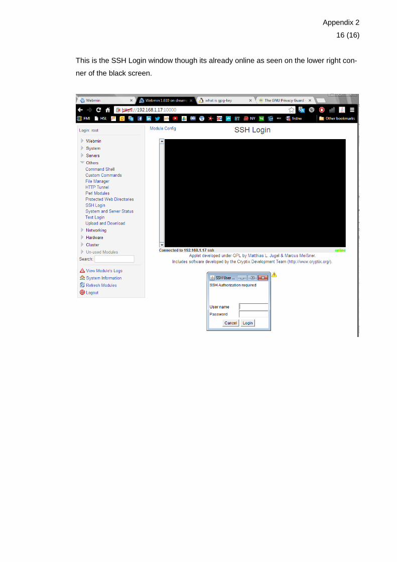
Appendix 2
16 (16)
This is the SSH Login window though its already online as seen on the lower right con-
ner of the black screen.