emax - vf servis€¦ · · 2011-10-10e1 25 28 e2 28 32 e3 38 45 e4 50 48 e4/f 50 e6 70 80 e6/f...
TRANSCRIPT

Emax
Installation, service and maintenanceinstructions for the fixed part of withdrawableversion circuit-breakers
Installation andservice instructions
1SDH000461R0002 L2778

L2234Emax
ABB SACE
Index
1. Description ..................................................................................................................................................................................... page 1
1.1 General characteristics ................................................................................................................................................................. « 11.2 Fixed part construction characteristics ........................................................................................................................................ « 1
2. Checking on receipt ....................................................................................................................................................................... « 1
3. Storage, lifting and weights ............................................................................................................................................................ « 1
4. Installation ....................................................................................................................................................................................... « 2
4.1 Installation room ............................................................................................................................................................................. « 24.2 Installation of the fixed part of withdrawable circuit-breaker ........................................................................................................ « 24.2.1 Preparation of the fixed part .......................................................................................................................................................... « 24.2.2 Installation of the fixed part ............................................................................................................................................................ « 34.2.3 Installation of the fixed part on board a ship .................................................................................................................................. « 44.3 Installation of the flange on the compartment door ....................................................................................................................... « 4
5. Electrical connections .................................................................................................................................................................... « 5
5.1 Connections to the power circuit ................................................................................................................................................... « 55.1.1 Shapes of the terminals ................................................................................................................................................................. « 55.1.2 Examples of positioning the connection busbars according to the types of terminal ................................................................. « 55.1.3 Assembly procedures of the connection busbars ........................................................................................................................ « 65.2 Earthing ........................................................................................................................................................................................... « 75.3 Wiring the circuit-breaker auxiliary circuits ................................................................................................................................... « 75.3.1 Withdrawable circuit-breaker ......................................................................................................................................................... « 7
6. Fixed part accessories .................................................................................................................................................................. « 86.1 Electrical accessories .................................................................................................................................................................... « 86.1.1 Auxiliary contacts ........................................................................................................................................................................... « 86.2 Mechanical accessories ................................................................................................................................................................ « 86.2.1 Accessory for shutter padlock ...................................................................................................................................................... « 86.2.2 Mechanical lock on compartment door ......................................................................................................................................... « 86.2.3 Interlock between circuit-breakers ................................................................................................................................................ « 8
7. Overall dimensions ........................................................................................................................................................................ « 9
8. Circuit diagrams ............................................................................................................................................................................. « 16
L2778Doc. N°
Model Apparatus
Dwg. Title
App.
Resp.Off.
Take-over Off.
Scale
Language
en
1SDH000461R0002
Installation, service and maintenanceinstruction for the fixed part ofwithdrawable version circuit-breakers

L2234 Emax
1/2 5Doc. N°
Model Apparatus Scale
Page N°1SDH000461R0002
L2778
2b
1
2a
3
4
5
6
7
8
9
1.2 Fixed part construction characteristics
Fig. 1
Fig. 2 Fig. 3
2. Checking on receipt
Examine the state of the material received and its consistency with the content of the order. Should any damage or errors be found on unpacking,which must be carried out carefully, make the relative notification within and not over 5 days from the receipt of the material. The notification mustindicate the number of the shipping note.
3. Storage, lifting and weights
The fixed part, protected by an external wooden crate, is fixed by means of screws to the transport pallet or to the bottom of the packing case.If the fixed part has to remain in the warehouse even for a short time before being put into service, after checking it on receipt, it must be put backin its container and covered with a waterproof sheet.
Caution– Use a dry, dust-free room free of aggressive chemical agents as a storage room– Position the fixed part on a horizontal surface, not in direct contact with the floor, but on a suitable support surface (Fig. 2)– The maximum number of stackable circuit-breakers is indicated in figure 3.
1 Steel sheet supporting structure2 Earthing contacts (a: for all versions; b: for E4,
E6)3 Safety shutters (IP20 degree of protection)4 Insulating terminal support base5 Terminals6 Contacts for signalling connected/test
isolated/disconnected (on request)7 Sliding contacts8 Padlock for safety shutters (on request))9 Anti-racking-in lock for circuit-breakers of
different size10 Fixing holes (qty 4 for E1, E2, E3, 6 for E4, E6)
1. Description
1.1 General CharacteristicsThe SACE Emax series of circuit-breakers consists of a steel sheet structure which houses the operating mechanism, the poles and the auxiliaryparts. Each pole, insulated from the others, contains the circuit-breaking parts and the current transformer of the corresponding phase.The structure of the poles differs according to whether the circuit-breaker is selective or current-limiting.The fixed version circuit-breaker has its own terminals for connection to the power circuit; in the withdrawable version the circuit-breaker comprisesthe moving part of the apparatus, which is completed with a fixed part fitted with the terminals for connection to the power circuit of the installation.The moving part and the fixed part are coupled by means of special contacts installed in the fixed part.

L2234 Emax
2/2 5
L2778Doc. N°
Model Apparatus Scale
Page N°1SDH000461R0002
4.2 Installation of the fixed part of the withdrawable circuit-breaker
4.2.1 Preparation of the fixed part
Assembly of the anti-racking-in lock
Before installing the fixed part, it is necessary to check the presence of the anti-racking-in lock for circuit-breakers with different electricalcharacteristics from those of the fixed part; if the anti-racking-in lock has been supplied separately, proceed to assemble it as follows:– On the self-adhesive plate (4), find the assembly position of the stop bolts in relation to the circuit-breaker which has to be housed in the fixed
part– Insert the hexagonal-head screws (1) in the holes found in the previous item as shown in the figure– Fix the screw with the washer (2) and nut (3).Make sure that the anti-racking-in lock corresponding to the one installed on the fixed part is present on the circuit-breaker (moving part).
Table of the fixed parts weights (Kg.)
4. Installation
4.1 Installation roomInstall the circuit-breaker in a dry, dust-free, non-corrosive room, and in such a way that it is not subject to shocks or vibrations; where this is notpossible, install it inside a switchboard with a suitable degree of protection.For the preparation of the installation room, please refer to the "Overall dimensions" chapter, which gives information on the following points:– minimum installation volumes of the circuit-breakers and derived versions– distances to be respected for circuit-breakers in compartments– overall dimensions of the circuit-breakers– fixing drillings– compartment door drillings
The installation, commissioning and any ordinary and extraordinary maintenance have to be done by skilled personnel, with a detailed knowledgeof the apparatus.
Fig. 4
With regard to lifting, follow the instructions: the fixed part must be placed on a sturdy supporting surface and lifted, preferably, by means of aspecial fork-lift truck. However, the use of ropes is allowed. In this case, the lifting ropes must be hooked up as shown in the figures.
NoteThe above table refers to fixed parts with horizontal back terminals.
Fixed part 3 poles withdrawable 4 poles withdrawable
kg kg
E1 25 28
E2 28 32
E3 38 45
E4 50 48
E4/f 50
E6 70 80
E6/f 85

L2234 Emax
3/2 5Doc. N°
Model Apparatus Scale
Page N°1SDH000461R0002
L2778
E3H-VE2S-H
E3N-SE2B-N-LE1B-N
3
4
2
1
1
2
3
5
Fig. 5 Fig. 6
Example for E1B 08 according to the nameplate diagram
4.2.2 Installation of the fixed partAttach the fixed part by means of the screws (1), washer (2) and nut (3) (M8 x 16), supplied by ABB SACE. If other screws are used, make surethat the head of the screws does not extend more than 5.5 mm from the base of the fixed part.
Fig. 7
Notes(*) For the E1-E2-E3 fixed parts,there are four fixing points, whereasthere are six for E4-E6.
1
2
3

L2234 Emax
4/2 5
L2778Doc. N°
Model Apparatus Scale
Page N°1SDH000461R0002
4.2.3 Installation of the fixed part on board a shipRegarding the fixing points of the SACE Emax withdrawable version air circuit-breakers, for applications on board a ship, additional fixing on thesides of the fixed part itself is recommended (the M12 screws and the spacers are not provided in the supply).
E1 - E2 - E3
E4 - E6
Spaces
Spaces
Fig. 8
4.3 Installation of the flange on the compartment door (Fig. 9)– Make the compartment door drillings specified in the "Overall dimensions" paragraph.– Attach the flange (1) on the front of the compartment door, fixing it from the inside by means of the self-tapping screws (2).
Fig. 9
1 2
L2234 Emax
5/2 5Doc. N°
Model Apparatus Scale
Page N°1SDH000461R0002
L2778
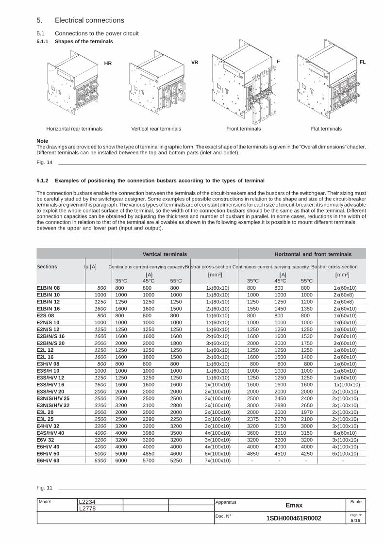
5. Electrical connections
5.1 Connections to the power circuit5.1.1 Shapes of the terminals
Fig. 14
NoteThe drawings are provided to show the type of terminal in graphic form. The exact shape of the terminals is given in the "Overall dimensions" chapter.Different terminals can be installed between the top and bottom parts (inlet and outlet).
5.1.2 Examples of positioning the connection busbars according to the types of terminal
The connection busbars enable the connection between the terminals of the circuit-breakers and the busbars of the switchgear. Their sizing mustbe carefully studied by the switchgear designer. Some examples of possible constructions in relation to the shape and size of the circuit-breakerterminals are given in this paragraph. The various types of terminals are of constant dimensions for each size of circuit-breaker: it is normally advisableto exploit the whole contact surface of the terminal, so the width of the connection busbars should be the same as that of the terminal. Differentconnection capacities can be obtained by adjusting the thickness and number of busbars in parallel. In some cases, reductions in the width ofthe connection in relation to that of the terminal are allowable as shown in the following examples.It is possible to mount different terminalsbetween the upper and lower part (input and output).
Fig. 11
Flat terminalsHorizontal rear terminals Vertical rear terminals Front terminals
HR VR F FL
Vertical terminals Horizontal and front terminals
Sections Iu [A] Continuous current-carrying capacityBusbar cross-section Continuous current-carrying capacity Busbar cross-section
[A] [mm2] [A] [mm2]35°C 45°C 55°C 35°C 45°C 55°C
E1B/N 08 800 800 800 800 1x(60x10) 800 800 800 1x(60x10)E1B/N 10 1000 1000 1000 1000 1x(80x10) 1000 1000 1000 2x(60x8)E1B/N 12 1250 1250 1250 1250 1x(80x10) 1250 1250 1200 2x(60x8)E1B/N 16 1600 1600 1600 1500 2x(60x10) 1550 1450 1350 2x(60x10)E2S 08 800 800 800 800 1x(60x10) 800 800 800 1x(60x10)E2N/S 10 1000 1000 1000 1000 1x(60x10) 1000 1000 1000 1x(60x10)E2N/S 12 1250 1250 1250 1250 1x(60x10) 1250 1250 1250 1x(60x10)E2B/N/S 16 1600 1600 1600 1600 2x(60x10) 1600 1600 1530 2x(60x10)E2B/N/S 20 2000 2000 2000 1800 3x(60x10) 2000 2000 1750 3x(60x10)E2L 12 1250 1250 1250 1250 1x(60x10) 1250 1250 1250 1x(60x10)E2L 16 1600 1600 1600 1500 2x(60x10) 1600 1500 1400 2x(60x10)E3H/V 08 800 800 800 800 1x(60x10) 800 800 800 1x(60x10)E3S/H 10 1000 1000 1000 1000 1x(60x10) 1000 1000 1000 1x(60x10)E3S/H/V 12 1250 1250 1250 1250 1x(60x10) 1250 1250 1250 1x(60x10)E3S/H/V 16 1600 1600 1600 1600 1x(100x10) 1600 1600 1600 1x(100x10)E3S/H/V 20 2000 2000 2000 2000 2x(100x10) 2000 2000 2000 2x(100x10)E3N/S/H/V 25 2500 2500 2500 2500 2x(100x10) 2500 2450 2400 2x(100x10)E3N/S/H/V 32 3200 3200 3100 2800 3x(100x10) 3000 2880 2650 3x(100x10)E3L 20 2000 2000 2000 2000 2x(100x10) 2000 2000 1970 2x(100x10)E3L 25 2500 2500 2390 2250 2x(100x10) 2375 2270 2100 2x(100x10)E4H/V 32 3200 3200 3200 3200 3x(100x10) 3200 3150 3000 3x(100x10)E4S/H/V 40 4000 4000 3980 3500 4x(100x10) 3600 3510 3150 6x(60x10)E6V 32 3200 3200 3200 3200 3x(100x10) 3200 3200 3200 3x(100x10)E6H/V 40 4000 4000 4000 4000 4x(100x10) 4000 4000 4000 4x(100x10)E6H/V 50 5000 5000 4850 4600 6x(100x10) 4850 4510 4250 6x(100x10)E6H/V 63 6300 6000 5700 5250 7x(100x10) - - - -

L2234 Emax
6/2 5
L2778Doc. N°
Model Apparatus Scale
Page N°1SDH000461R0002
Positioning the first anchoring baffle of the busbars according to the short-circuit currentAnchoring to the switchgear
Fig. 12
FLAT
FRONT
VERTICAL
HORIZONTAL
P E1-E2 E3-E4-E6 E1-E6
HORIZONTALI 250 150 –VERTICAL 250 150 –FRONT – – 250FLAT – – 250
5.1.3 Assembly procedure for the connection busbarsCheck the state of the contact surfaces of the connections very carefully: they must be very clean with no burrs, dents or traces of rust which mustbe eliminated using a fine file or an emery cloth to prevent localized increases in temperature. On completion of the operation, remove all tracesof grease or dust with a cloth soaked in a suitable solvent. When copper connections are used, it is advisable to tin-plate the contact surfaces.When aluminium connections are used, it is advisable to apply a thin layer of Vaseline over the contact surfaces.The connections must not exert any strain on the terminals in any directionAlways insert a large diameter flar washer and a spring washer between them (to spread the tightening pressure over a greater area).Make the contact between connection and terminal and tighten the fixing screws completely.Always use two wrenches (so as not to strain the insulating parts excessively), applying the tightening torque 70 Nm and use M12 high resistancescrews. Check tightness after 24 hours.
Fig. 13
2 2
3 3
4 2
4 4
6 3
6 6
Fixed part terminals No. screws for phase No. screws for neutral
2 2
3 3
4 2
4 4
6 3
6 6
Fixed circuit-breaker terminals No. screws for phase No. screws for neutral
L2234 Emax
7/2 5Doc. N°
Model Apparatus Scale
Page N°1SDH000461R0002
L2778
5.2 EarthingThe fixed part of the withdrawable circuit-breaker have one or two terminals on the rear, marked with the special symbol, for connection to earth(Fig. 7).Each terminal is complete with a bolt for fixing the connection.A conductor with a cross-section conforming to current standards must be used for the connection. Before assembling the connection, clean anddegrease the area around the screw. After the assembly tighten the bolt with a torque of 70 Nm.
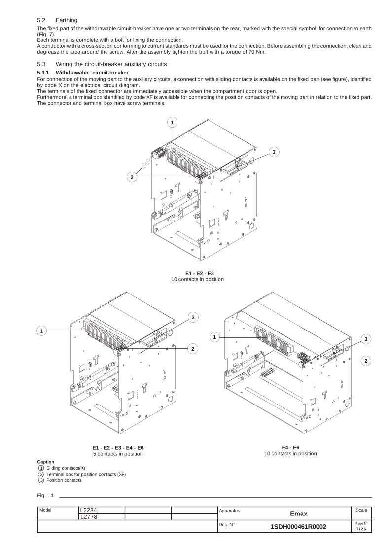
5.3 Wiring the circuit-breaker auxiliary circuits
1
2
3
1
2
3
31
2
5.3.1 Withdrawable circuit-breakerFor connection of the moving part to the auxiliary circuits, a connection with sliding contacts is available on the fixed part (see figure), identifiedby code X on the electrical circuit diagram.The terminals of the fixed connector are immediately accessible when the compartment door is open.Furthermore, a terminal box identified by code XF is available for connecting the position contacts of the moving part in relation to the fixed part.The connector and terminal box have screw terminals.
E1 - E2 - E3 - E4 - E65 contacts in position
E4 - E610 contacts in position
E1 - E2 - E3
Fig. 14
Caption1 Sliding contacts(X)2 Terminal box for position contacts (XF)3 Position contacts
10 contacts in position
L2234 Emax
8/2 5
L2778Doc. N°
Model Apparatus Scale
Page N°1SDH000461R0002
Un In max T
125 V DC 0.3 A 10 ms
250 V DC 0.15 A 10 ms
Un In max cosϕϕϕϕϕ
250 V AC 5 A 0.3
Electrical signalling for circuit-breaker connected/test isolated/disconnected (Fig. 15)In addition to mechanical signalling of the position of the circuit-breaker, it is possible to have electrical signalling by means of 5 or 10 auxiliarycontacts which are installed on the fixed part.Only available for circuit-breakers in withdrawable versions for installing on the fixed part.The auxiliary contacts can have the following configurations:Reference figures in the electrical circuit diagrams: S75I (31-32) – S75T (31-32) – S75E (31-32)– 5 contacts; group consisting of 2 connected signalling contacts, 2 disconnected signalling contacts and 1 test position signalling contact (main
contacts isolated, but sliding contacts connected)– 10 contacts; group consisting of 4 connected signalling contacts, 4 disconnected signalling contacts and 2 test position signalling contacts
(main contacts isolated, but sliding contacts connected).
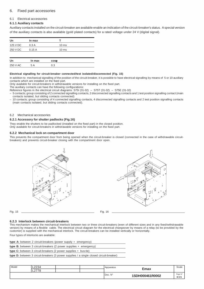
6.2 Mechanical accessories6.2.1 Accessory for shutter padlocks (Fig.16)They enable the shutters to be padlocked (installed on the fixed part) in the closed position.Only available for circuit-breakers in withdrawable versions for installing on the fixed part.
6.2.2 Mechanical lock on compartment doorThis prevents the compartment door from being opened when the circuit-breaker is closed (connected in the case of withdrawable circuit-breakers) and prevents circuit-breaker closing with the compartment door open.
6.2.3 Interlock between circuit-breakersThis mechanism makes the mechanical interlock between two or three circuit-breakers (even of different sizes and in any fixed/withdrawableversion) by means of a flexible cable. The electrical circuit diagram for the electrical changeover by means of a relay (to be provided by thecustomer) is supplied with the mechanical interlock. The circuit-breakers can be installed vertically or horizontally.
6. Fixed part accessories
6.1 Electrical accessories6.1.1 Auxiliary contactsAuxiliary contacts installed on the circuit-breaker are available enable an indication of the circuit-breaker's status. A special versionof the auxiliary contacts is also available (gold plated contacts) for a rated voltage under 24 V (digital signal).
Four types of interlocks are available:
type A: between 2 circuit-breakers (power supply + emergency)
type B: between 3 circuit-breakers (2 power supplies + emergency)
type C: between 3 circuit-breakers (2 power supplies + bus-tie)
type D: between 3 circuit-breakers (3 power supplies / a single closed circuit-breaker)
Fig. 15 Fig. 16

L2234 Emax
9/2 5Doc. N°
Model Apparatus Scale
Page N°1SDH000461R0002
L2778
E1 E2/E3/E4/E6
E1 414 324 162 162 10 – –
E2 414 324 162 162 8 – –
E3 558 432 216 216 8 370 490
E4 684 594 252 342 8 530 610
E4/f 774 - - 342 8 – 700
E6/f 1062 - - 468 8 - 1000
E6 936 810 342 468 8 750 870
1SD
C20
0220
F00
01
1SD
C20
0221
F00
01
7. Overall dimensions
Withdrawable circuit-breaker
Basic version with horizontal rear terminals
E1/E2
View A
E3
View A
3 POLES
3 POLES4 POLES
4 POLES
4 POLES
3 POLES
4 POLES
3 POLES
A B C D E F3poles 4 poles
Fig. 17
Caption
1 Inside edge of compartmentdoor
2 Segregation(where foreseen)
3 Fixing fixed part Ø 10drilling (use M8 screws)
4 No. 1 M12 screw (E1, E2, E3) orno. 2 M12 screws (E4, E6) forearthing (included in the supply)
5 Run from connected for a TESTto isolated
6 Alternative drilling with 25 mmpitch for fixing fixed part
7 Ventilation drilling on theswitchgear

L2234 Emax
10/25
L2778Doc. N°
Model Apparatus Scale
Page N°1SDH000461R0002
E4View A
E6View A
3 POLES (E4)
4 POLES (E4)
4 POLES (E4/f)
3 POLES (E6)
4 POLES (E6)
4 POLES (E6/f)
Withdrawable circuit-breaker
Basic version with horizontal rear terminals
1SD
C20
0222
F00
01
1SD
C20
0223
F00
01
Fig. 18

L2234 Emax
11/25Doc. N°
Model Apparatus Scale
Page N°1SDH000461R0002
L2778
Fig. 19
E1 E2/E4 E3/E6
Captive M12included in thesupply
E1View A
E2View A
E3View A
E4View A
E6View A
E4/fView A
E6/fView A
Captive M12included in thesupply
Captive M12included in thesupply
Withdrawable circuit-breaker
Basic version with vertical rear terminals
1SD
C20
0224
F00
01

L2234 Emax
12/25
L2778Doc. N°
Model Apparatus Scale
Page N°1SDH000461R0002
Fig. 20
E1
E2
E3
Withdrawable circuit-breaker
Version with front terminals
1SD
C20
0225
F00
01

L2234 Emax
13/25Doc. N°
Model Apparatus Scale
Page N°1SDH000461R0002
L2778
Fig. 21
E4
E6 E6 E6/f
E4 E4/f
Withdrawable circuit-breaker
Version with flat terminals

L2234 Emax
14/25
L2778Doc. N°
Model Apparatus Scale
Page N°1SDH000461R0002
E1 E2-E3-E4-E4/f-E6-E6/f
Fig. 22
Withdrawable circuit-breaker
Version with flat terminals
E1
View A
E2
View A
E3
View A
E4
View A
E6
View A
E4/f
View A
E6/f
View A
L2234 Emax
15/25Doc. N°
Model Apparatus Scale
Page N°1SDH000461R0002
L2778
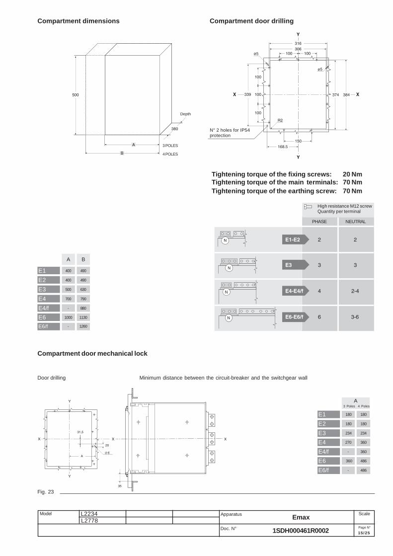
A B
E1 400 490
E2 400 490
E3 500 630
E4 700 790
E4/f - 880
E6 1000 1130
E6/f - 1260
Tightening torque of the fixing screws: 20 NmTightening torque of the main terminals: 70 NmTightening torque of the earthing screw: 70 Nm
Compartment dimensions Compartment door drilling
High resistance M12 screwQuantity per terminal
PHASE NEUTRAL
N° 2 holes for IP54protection
Depth
3 POLES
4 POLES
Fig. 23
Minimum distance between the circuit-breaker and the switchgear wallDoor drilling
Compartment door mechanical lock
E1 180 180
E2 180 180
E3 234 234
E4 270 360
E4/f - 360
E6 360 486
E6/f - 486
A 3 Poles 4 Poles

L2234 Emax
16/25
L2778Doc. N°
Model Apparatus Scale
Page N°1SDH000461R0002
8. Circuit diagrams
WarningBefore installing the circuit-breaker, carefully read notes F and O on the circuit diagrams.
Operating status shownThe circuit diagram is for the following conditions:- withdrawable circuit-breaker, open and racked-in- circuits de-energised- releases not tripped- motor operating mechanism with springs unloaded.
VersionsThe diagram shows a circuit-breaker in withdrawable version; it can be applied to a fixed version circuit-breaker as well.
Fixed versionThe control circuits are fitted between terminals XV (connector X is not supplied).With this version, the applications indicated in figures 31 and 32 cannot be provided.
Withdrawable versionThe control circuits are fitted between the poles of connector X (terminal box XV is not supplied).Version without overcurrent releaseWith this version, the applications indicated in figures 13, 14, 41, 42, 43, 44, 45, 46, 47, 48, 62 cannot be provided.
Version with PR121/P electronic releaseWith this version, the applications indicated in figures 42, 43, 44, 45, 46, 47, 48 cannot be provided.
Version with PR122/P electronic releaseWith this version, the applications indicated in figure 41 cannot be provided.
Version with PR123/P electronic releaseWith this version, the applications indicated in figure 41 cannot be provided.
Caption= Circuit diagram figure number
* = See note indicated by the letterA1 = Circuit-breaker accessoriesA3 = Accessories applied to the fixed part of the circuit-breaker (for withdrawable version only)A4 = Example switchgear and connections for control and signalling, outside the circuit-breakerA13 = PR021/K signalling unit (outside the circuit-breaker)AY = SACE SOR TEST UNIT Test/monitoring Unit (see note R)D = Electronic time-delay device of the undervoltage release, outside the circuit-breakerF1 = Delayed-trip fuseK51 = PR121/P, PR122/P, PR123/P electronic release with the following protection functions:
- L overload protection with inverse long time-delay trip-setting I1- S short-circuit protection with inverse or definite short time-delay trip-setting l2- I short-circuit protection with instantaneous time-delay trip-setting l3- G earth fault protection with inverse short time-delay trip-setting l4
K51/1...8 = Contacts for the PR021/K signalling unitK51/GZin(DBin)= Zone selectivity: for protection G (only with Vaux and PR122/P or PR123/P release) or "reverse" direction input for protection
D (only with Vaux and PR123/P release)K51/GZout(DBout) = Zone selectivity: for protection G (only with Vaux and PR122/P or PR123/P release) or "reverse" direction output for protection
D (only with Vaux and PR123/P release)K51/IN1 = Digital programmable input (available only with Vaux and release PR122/P or PR123/P with indicator module PR120/K)K51/P1...P4 = Programmable electrical signalling (available only with Vaux and release PR122/P or PR123/P with indicator module PR120/K)K51/SZin(Dfin) = Zone selectivity: input for protection S or "direct" input for protection D (only with Vaux and PR122/P or PR123/P release)K51/SZout(DFout) = Zone selectivity: output for protection S or "direct" output for protection D (only with Vaux and PR122/P or PR123/
P release)K51/YC = Closing control from PR122/P or PR123/P electronic release with communication module PR120/D-MK51/YO = Opening control from PR122/P or PR123/P electronic release with communication module PR120/D-MM = Motor for loading the closing springsQ = Circuit-breakerQ/1...27 = Circuit-breaker auxiliary contactsS33M/1...3 = Limit contacts for spring-loading motorS43 = Switch for setting remote/local controlS51 = Contact for electrical signalling of circuit-breaker open due to tripping of the overcurrent release. The circuit-breaker may be closed
only after pressing the reset pushbutton, or after energizing the coil for electrical reset (if available)S75E/1.4 = Contacts for electrical signalling of circuit-breaker in disconnected position (only with withdrawable circuit-breakers)S75I/1..5 = Contacts for electrical signalling of circuit-breaker in connected position (only with withdrawable circuit-breakers)S75T/1..4 = Contacts for electrical signalling of circuit-breaker in test isolated position (only with withdrawable circuit-breakers)CS = Pushbutton or contact for closing the circuit-breakerSO = Pushbutton or contact for opening the circuit-breakerSO1 = Pushbutton or contact for opening the circuit-breaker with delayed tripSO2 = Pushbutton or contact for opening the circuit-breaker with instantaneous tripSR = Pushbutton or contact for electrical circuit-breaker resetTI/L1 = Current transformer located on phase L1TI/L2 = Current transformer located on phase L2
L2234 Emax
17/25Doc. N°
Model Apparatus Scale
Page N°1SDH000461R0002
L2778
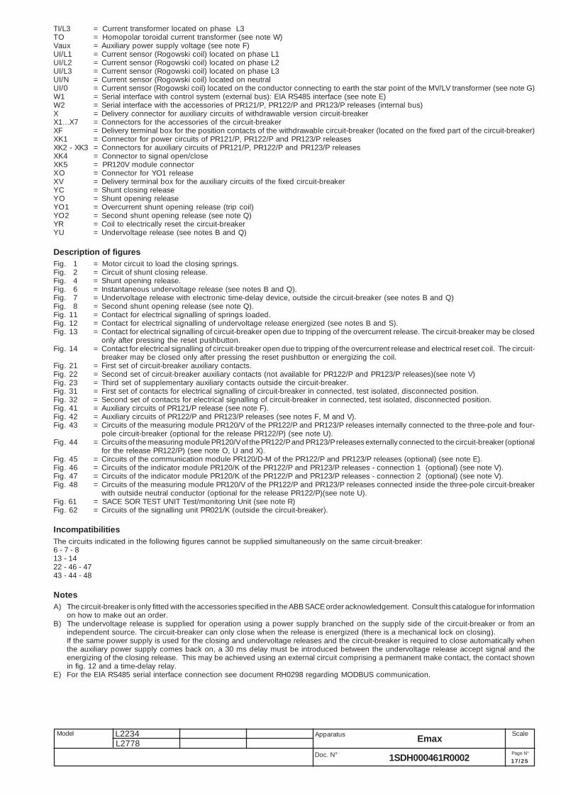
TI/L3 = Current transformer located on phase L3TO = Homopolar toroidal current transformer (see note W)Vaux = Auxiliary power supply voltage (see note F)UI/L1 = Current sensor (Rogowski coil) located on phase L1UI/L2 = Current sensor (Rogowski coil) located on phase L2UI/L3 = Current sensor (Rogowski coil) located on phase L3UI/N = Current sensor (Rogowski coil) located on neutralUI/0 = Current sensor (Rogowski coil) located on the conductor connecting to earth the star point of the MV/LV transformer (see note G)W1 = Serial interface with control system (external bus): EIA RS485 interface (see note E)W2 = Serial interface with the accessories of PR121/P, PR122/P and PR123/P releases (internal bus)X = Delivery connector for auxiliary circuits of withdrawable version circuit-breakerX1...X7 = Connectors for the accessories of the circuit-breakerXF = Delivery terminal box for the position contacts of the withdrawable circuit-breaker (located on the fixed part of the circuit-breaker)XK1 = Connector for power circuits of PR121/P, PR122/P and PR123/P releasesXK2 - XK3 = Connectors for auxiliary circuits of PR121/P, PR122/P and PR123/P releasesXK4 = Connector to signal open/closeXK5 = PR120V module connectorXO = Connector for YO1 releaseXV = Delivery terminal box for the auxiliary circuits of the fixed circuit-breakerYC = Shunt closing releaseYO = Shunt opening releaseYO1 = Overcurrent shunt opening release (trip coil)YO2 = Second shunt opening release (see note Q)YR = Coil to electrically reset the circuit-breakerYU = Undervoltage release (see notes B and Q)
Description of figuresFig. 1 = Motor circuit to load the closing springs.Fig. 2 = Circuit of shunt closing release.Fig. 4 = Shunt opening release.Fig. 6 = Instantaneous undervoltage release (see notes B and Q).Fig. 7 = Undervoltage release with electronic time-delay device, outside the circuit-breaker (see notes B and Q)Fig. 8 = Second shunt opening release (see note Q).Fig. 11 = Contact for electrical signalling of springs loaded.Fig. 12 = Contact for electrical signalling of undervoltage release energized (see notes B and S).Fig. 13 = Contact for electrical signalling of circuit-breaker open due to tripping of the overcurrent release. The circuit-breaker may be closed
only after pressing the reset pushbutton.Fig. 14 = Contact for electrical signalling of circuit-breaker open due to tripping of the overcurrent release and electrical reset coil. The circuit-
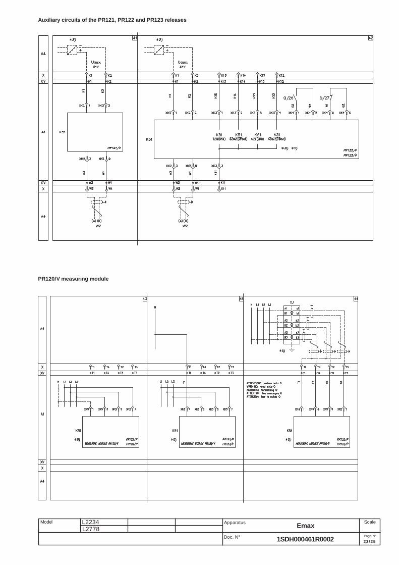
breaker may be closed only after pressing the reset pushbutton or energizing the coil.Fig. 21 = First set of circuit-breaker auxiliary contacts.Fig. 22 = Second set of circuit-breaker auxiliary contacts (not available for PR122/P and PR123/P releases)(see note V)Fig. 23 = Third set of supplementary auxiliary contacts outside the circuit-breaker.Fig. 31 = First set of contacts for electrical signalling of circuit-breaker in connected, test isolated, disconnected position.Fig. 32 = Second set of contacts for electrical signalling of circuit-breaker in connected, test isolated, disconnected position.Fig. 41 = Auxiliary circuits of PR121/P release (see note F).Fig. 42 = Auxiliary circuits of PR122/P and PR123/P releases (see notes F, M and V).Fig. 43 = Circuits of the measuring module PR120/V of the PR122/P and PR123/P releases internally connected to the three-pole and four-
pole circuit-breaker (optional for the release PR122/P) (see note U).Fig. 44 = Circuits of the measuring module PR120/V of the PR122/P and PR123/P releases externally connected to the circuit-breaker (optional
for the release PR122/P) (see note O, U and X).Fig. 45 = Circuits of the communication module PR120/D-M of the PR122/P and PR123/P releases (optional) (see note E).Fig. 46 = Circuits of the indicator module PR120/K of the PR122/P and PR123/P releases - connection 1 (optional) (see note V).Fig. 47 = Circuits of the indicator module PR120/K of the PR122/P and PR123/P releases - connection 2 (optional) (see note V).Fig. 48 = Circuits of the measuring module PR120/V of the PR122/P and PR123/P releases connected inside the three-pole circuit-breaker
with outside neutral conductor (optional for the release PR122/P)(see note U).Fig. 61 = SACE SOR TEST UNIT Test/monitoring Unit (see note R)Fig. 62 = Circuits of the signalling unit PR021/K (outside the circuit-breaker).
IncompatibilitiesThe circuits indicated in the following figures cannot be supplied simultaneously on the same circuit-breaker:6 - 7 - 813 - 1422 - 46 - 4743 - 44 - 48
NotesA) The circuit-breaker is only fitted with the accessories specified in the ABB SACE order acknowledgement. Consult this catalogue for information
on how to make out an order.B) The undervoltage release is supplied for operation using a power supply branched on the supply side of the circuit-breaker or from an
independent source. The circuit-breaker can only close when the release is energized (there is a mechanical lock on closing).If the same power supply is used for the closing and undervoltage releases and the circuit-breaker is required to close automatically whenthe auxiliary power supply comes back on, a 30 ms delay must be introduced between the undervoltage release accept signal and theenergizing of the closing release. This may be achieved using an external circuit comprising a permanent make contact, the contact shownin fig. 12 and a time-delay relay.
E) For the EIA RS485 serial interface connection see document RH0298 regarding MODBUS communication.

L2234 Emax
18/25
L2778Doc. N°
Model Apparatus Scale
Page N°1SDH000461R0002
F) The auxiliary voltage Vaux allows actuation of all operations of the PR121/P, PR122/P and PR123/P releases.Having requested a Vaux insulated from earth, one must use “galvanically separated converters” in compliance with IEC 60950 (UL 1950)or equivalent standards that ensure a common mode current or leakage current (see IEC 478/1, CEI 22/3) not greater than 3.5 mA, IEC 60364-41 and CEI 64-8.
G) Earth fault protection is available with the PR122/P and PR123/P releases by means of a current sensor located on the conductor connectingto earth the star center of the MV/LV transformer.The connections between terminals 1 and 2 (or 3) of current transformer UI/O and poles T7 and T8 of the X (or XV) connector must be madewith a two-pole shielded and stranded cable (type BELDEN 3105A/3105B) no more than 15m long. The shield must be earthed on the circuit-breaker side and current sensor side.
N) With releases PR122/P and PR123/P, the connections to the zone selectivity inputs and outputs must be made with a two-pole shielded andstranded cable (type BELDEN 3105A/3105B), no more than 300m long. The shield must be earthed on the selectivity input side.
O) Systems with a rated voltage greater than 690V require the use of an insulation voltage transformer to connect to the busbars (connect accordingto the diagrams on the sheet provided with the kit 1SDH000460R0508).
P) With releases PR122/P and PR123/P with communication module PR120/D-M, the coils YO and YC are controlled directly from contacts K51/YO and K51/YC with maximum voltages of 110-120 VDC and 240-250 VAC.
Q) The second shunt opening release may be installed as an alternative to the undervoltage release.R) The SACE SOR TEST UNIT + opening release (YO) is guaranteed to operate starting at 75% of the Vaux of the opening release itself.
While the YO power supply contact is closing (short-circuit on terminals 4 and 5), the SACE SOR TEST UNIT is unable to detect the openingcoil status.Consequently:- For continuously powered opening coil, the TEST FAILED and ALARM signals will be activated- If the coil opening command is of the pulsing type, the TEST FAILED signal may appear at the same time. In this case, the TEST FAILED
signal is actually an alarm signal only if it remains lit for more than 20s.S) Also available in the version with normally-closed contactU) The measuring module PR120/V is always supplied with relay PR123/P.V) If fig. 22 is present (second set of auxiliary contacts) simultaneously as relay PR122/P (or PR123/P), the contacts for the zone selectivity in fig.
42 (K51/Zin, K51/Zout, K51/Gzin and K51/Gzout) are not wired. In addition, the indicator module PR120/K in figures 46 and 47 cannot besupplied.
W) For the connections between TO toroidal transformer and poles of CB X (or XV) connector, use a shielded 4-pole cable with paired braidedwires (BELDEN 9696 paired type), length not exceeding 10m. The shielding will be grounded on CB side.
X) T3 and T4 poles of X (or XV) connector are used to measure voltage when U>690V. In this case, they must be connected to the secondarywinding of the TU voltage transformer (see fig. 44). Ask ABB SACE for applications of the residual current protection with voltages higher than690V.
Y) The shielding of the connection cable will be grounded on CB side only. The connection must be made with a two-pole shielded and strandedcable (type BELDEN 3105A) no more than 15m long.

L2234 Emax
19/25Doc. N°
Model Apparatus Scale
Page N°1SDH000461R0002
L2778
Circuit diagram symbols (IEC 60617 and CEI 3-14 ... 3-26 Standards)
Shield(may be drawnin any shape)
Delay
Mechanical or electricalconnection
Manually operatedcontrol (general case)
Operated by turning
Operated by pushing
Equipotentiality
Terminal
Plug and socket(male and female)
Motor(general symbol)
Current transformer
Voltage transformer
Winding of three-phasetransformer, connectionstar
Position switch (limit switch)change-over break beforemake contact
Circuit-breaker-disconnectorwith automatic release
Switch-disconnector(on-load isolating switch)
Operating device(general symbol)
Instantaneousovercurrent or rate-of-riserelay
Overcurrent relay withadjustable short time-lagcharacteritic
Converter withgalvanic separator
Conductors in a screenedcable (i.e., 3 conductorsshown)
Twisted conductors (i.e., 3conductors shown)
Connection of conductors
Make contact
Break contact
Change-over break beforemake contact
Position switch (limitswitch), make contact
Position switch (limitswitch), break contact
Overcurrent relay withinverse short time-lagcharacteritic
Overcurrent relaywith inverse long time-lagcharacteritic
Earth fault overcurrent relaywith inverse short time-lagcharacteritic
Fuse(general symbol)
Current sensingelement

L2234 Emax
20/25
L2778Doc. N°
Model Apparatus Scale
Page N°1SDH000461R0002
Circuit diagram - Operating status
Morsetto
non connesso
Morsetto
non connesso
Four-pole circuit-breaker with PR121/P, PR122/P, PR123/P electronicrelease
Three-pole circuit-breaker with PR121/P, PR122/P or PR123/P electronicrelease
Three-or four-pole switch-disconnectorThree-pole circuit-breaker with PR122/P or PR123/P electronic release,residual current protection and U<=690V.
* G)* G)
UI/N
PE
PE N
T6T6
UI/L1
N
TO
L1
UI/L3
UI/L2
L2 L3
1
2
3
4
TI/L2
TI/L3
TI/L1
Q
L1 L2 L3
T8
X
T5
T4
T3
W)*
T7
X
T8 7T8
XV
T5 T43
T44
X)
T4
*
T3
T4
T3
XK1
8
7
4
6
T34
XV
T7 T7
T24
T33
T14
T23
6
XK2
8
4
5
2
3
T13
T31
T32
T12
T21
T22
T11
XK1
1
14
13
XK1
10
12
11
9
12
Y01>>>
>>
>>
2
XO
1
XO
>>
>
K51
Idn: 3A...30A
PR123/P
PR122/P
* Y)
* Y)
Terminal not connected
Terminal not connected

L2234 Emax
21/25Doc. N°
Model Apparatus Scale
Page N°1SDH000461R0002
L2778
Motor operating mechanism, opening, closing and undervoltage releases
Signalling contacts

L2234 Emax
22/25
L2778Doc. N°
Model Apparatus Scale
Page N°1SDH000461R0002
Signalling contacts
L2234 Emax
23/25Doc. N°
Model Apparatus Scale
Page N°1SDH000461R0002
L2778
Auxiliary circuits of the PR121, PR122 and PR123 releases
PR120/V measuring module

L2234 Emax
24/25
L2778Doc. N°
Model Apparatus Scale
Page N°1SDH000461R0002
PR120/K signalling module
PR120/D-M communication module

L2234 Emax
25/25Doc. N°
Model Apparatus Scale
Page N°1SDH000461R0002
L2778
PR021/K signalling unit
PR122
P
PR121/P
PR122/P
PR123/P

1SD
H00
0461
R00
02
L27
78
ABB SACE S.p.A.L.V. BreakersVia Baioni, 35 - 24123 Bergamo - ItalyTel.: +39 035.395.111 - Telefax: +39 035.395.306-433
http://www.abb.com
Due to possible developments of standards as well as ofmaterials, the characteristics and dimensions specified inthe present catalogue may only be considered binding afterconfirmation by ABB SACE.