ema omap3530 evm linux psp kernel user guide · 2. built with linux kernel version 2.6.29-rc3. 3....
TRANSCRIPT

TI-DM3730-EM Linux PSP Kernel
User Guide

2
I
Table of Contents
Table of Contents ........................................................................................................................1
Read This First ........................................................................................................................... 1
About This Manual ................................................................................................................ 2
How to Use This Manual........................................................................................................ 3
Notation of information elements ........................................................................................ 4
If You Need Assistance .......................................................................................................... 4
Installation ................................................................................................................................. 5
System Requirements............................................................................................................ 6
Installation ............................................................................................................................. 6
Installation Steps ................................................................................................................... 7
Environment Setup ................................................................................................................ 7
Kernel ........................................................................................................................................ 8
Compiling Linux Kernel .......................................................................................................... 9
Configuring Linux Kernel ....................................................................................................... 9
Booting Linux Kernel............................................................................................................ 10
Brief of Drivers..................................................................................................................... 11
Linux PSP details .............................................................................................................. 11
Device driver list .............................................................................................................. 11
Drivers not supported ..................................................................................................... 12
Audio Driver............................................................................................................................. 13
Introduction......................................................................................................................... 14
References ....................................................................................................................... 15
Acronyms & Definitions................................................................................................... 15
Features ............................................................................................................................... 16
Features Supported ......................................................................................................... 16
Constraints....................................................................................................................... 16
Driver Configuration ............................................................................................................ 17

II
Software Interfaces ............................................................................................................. 21
Application Interface ....................................................................................................... 21
Driver Interface ................................................................................................................... 23
Description ...................................................................................................................... 23
Sample Applications ............................................................................................................ 25
Introduction..................................................................................................................... 25
A minimal playback application....................................................................................... 25
A minimal record application .......................................................................................... 29
Display Driver .......................................................................................................................... 33
Introduction......................................................................................................................... 34
References ....................................................................................................................... 34
Acronyms & Definitions................................................................................................... 34
Hardware Overview......................................................................................................... 34
Features ............................................................................................................................... 36
Overview.......................................................................................................................... 36
Usage ............................................................................................................................... 36
Architecture ......................................................................................................................... 49
Driver Architecture .......................................................................................................... 49
Software Design Interfaces ............................................................................................. 49
Software Interfaces ............................................................................................................. 51
'fbdev' Driver Interface.................................................................................................... 51
V4L2 Driver Interface....................................................................................................... 52
SYSFS Software Design Interfaces ................................................................................... 54
Driver Configuration ............................................................................................................ 55
Configuration Steps ......................................................................................................... 55
Installation ....................................................................................................................... 58
USB Driver................................................................................................................................ 60
Introduction......................................................................................................................... 61
References ....................................................................................................................... 61
Hardware Overview......................................................................................................... 61

Features ............................................................................................................................... 62
III
Supported ........................................................................................................................ 62
Limitations ....................................................................................................................... 62
Driver configuration ............................................................................................................ 63
USB phy selection for MUSB OTG port............................................................................ 63
USB controller in host mode ........................................................................................... 63
MUSB OTG controller in gadget mode ............................................................................ 64
MUSB OTG controller in OTG mode ................................................................................ 64
Software Interface ............................................................................................................ 65
sysfs ................................................................................................................................. 65
procfs ............................................................................................................................... 65
MMC Driver ............................................................................................................................. 66
Introduction......................................................................................................................... 67
References ....................................................................................................................... 67
Acronyms & Definitions................................................................................................... 67
Features ............................................................................................................................... 68
Features Supported ......................................................................................................... 68
Features Not Supported .................................................................................................. 68
Limitations ....................................................................................................................... 68
Power Management ................................................................................................................ 69
Introduction......................................................................................................................... 70
References ....................................................................................................................... 70
Features ............................................................................................................................... 71
Supported ........................................................................................................................ 71
Not Supported ................................................................................................................. 71
Limitations ....................................................................................................................... 71
Architecture ......................................................................................................................... 72
cpuidle ............................................................................................................................. 72
Dynamic Tick Suppression ............................................................................................... 74
Suspend & Resume.......................................................................................................... 74

IV
Configuration ....................................................................................................................... 75
cpuidle ............................................................................................................................. 75
cpufreq ............................................................................................................................ 77
SmartReflex ..................................................................................................................... 77
Software Interface ............................................................................................................... 79
cpuidle ............................................................................................................................. 79
Suspend & Resume.......................................................................................................... 80
SmartReflex ..................................................................................................................... 81
Release Note............................................................................................................................ 82
General Information ............................................................................................................ 85
Tool Chain Version Used In This Release ......................................................................... 85
Limitations ....................................................................................................................... 85
Drivers ................................................................................................................................. 86
Baseport .......................................................................................................................... 86
Audio Driver..................................................................................................................... 86
NAND Driver .................................................................................................................... 87
USB Driver........................................................................................................................ 87
V4L2 and FBDEV Display Driver ....................................................................................... 89
Ethernet Driver ................................................................................................................ 91
MMC/SD Driver ............................................................................................................... 92
Touch Screen Driver ........................................................................................................ 93
Power Management ........................................................................................................ 93

1

2

3
How to Use This Manual
This document includes the following chapters:
Chapter 1, Installation - describes the installation procedure for
The PSP package.
Chapter 2, Kernel - describes the procedure to build and
execute the Linux kernel.
Chapter 3, Audio Driver - describes the implementation of audio
driver.
Chapter 4, Display Driver - describes the implementation of
video, display driver.
Chapter 5, USB Driver - describes the implementation of USB
driver.
Chapter 6, MMC Driver - describes the implementation of MMC
driver.
Chapter 7, Power Management - describes the power
management frameworks.
Chapter 8, Release Note - describes the details about this
release.
Please go through the Release Notes before starting the
installation.

4
Notation of information elements
The document may contain these additional elements:
Warning
This is an example of warning message. It usually indicates a
non-recoverable change, e.g. formatting a file system.
Caution
This is an example of caution message.
Important
This is an example of important message.
Note
This is an example of additional note. This usually indicates
additional information in the current context.
Tip
This is an example of a useful tip.
If You Need Assistance
For any assistance, please send an mail to software support
Mailto: [email protected]

5
Installation

6
System Requirements
Hardware Requirements:
TI-DM3730-EM-M Main Board (REV A2 or later) and TI-
DM3730-EM
EV-C Core Board with OMAP35x ES 2.1/3.1 Processor (REV A3
or later) This release also supports the OMAP EVM2 Main board
with ES3.1 processor.
Software Requirements:
Code Sourcery ARM tool chain version 2008-q1
Installation
Find a directory named TI-DM3730-EM-PSP-02.01.03.11
with the following contents:
TI-DM3730-EM-PSP-02.01.03.11/
|-- docs
| `-- User Guide.pdf
|-- host-tools
| |-- linux
| | `-- signGP
| `-- src
| `-- signGP.c
|-- images
| |-- boot-strap
| | `-- MLO
| |-- examples
| |-- fs
| | |--
Angstrom-console-image-glibc-ipk-2009.X-stable-beagleboard.ro
otfs.tar.bz2
| | `--
Angstrom-x11-image-glibc-ipk-2009.X-stable-beagleboard.rootfs
.tar.bz2
| |-- kernel
| | `-- uImage
| `-- u-boot
| `-- u-boot.bin
`-- src
|-- kernel
| `-- ema_psp-02.01.03.11_kernel.tar.bz2
`-- u-boot

7
`-- u-boot-release_20091118.tar.bz2
Installation Steps
To use the pre-built binaries included in the release, speed up your
progress. You can always return to the instructions on how to build
the Linux kernel yourself.
Environment Setup
1. Set the environment variable PATH to contain the binaries of
the CodeSourcery cross-compiler tool-chain.
For example, in bash:
$ export PATH=/opt/toolchain/2008-q1/bin:$PATH
2. Add location of u-boot tools to the PATH environment variable.
For example, in bash:
$ export PATH=/opt/u-boot/tools:$PATH
Note
Actual instructions and the path setting will depend upon
your shell and location of the tools

8
Kernel

9
Compiling Linux Kernel
Change to the base of the Linux source directory.
Create default configuration for the OMAP3EVM.
$ make CROSS_COMPILE=arm-none-linux-gnueabi- ARCH=arm
TI-DM3730-EM_evm_defconfig
Initiate the build.
Note
For the kernel image(uImage) to be built, mkimage utility
must be included in the path. mkimage utility is
generated(under tools folder) while building u-boot.bin
$ make CROSS_COMPILE=arm-none-linux-gnueabi- ARCH=arm uImage
On successful completion, file uImage will be created in the
directory ./arch/arm/boot.
Copy this file to the SD card or burn it into right place of the nand
flash.
Configuring Linux Kernel
Enter following command to make changes to default configuration.
The configuration options for various drivers will be described in
later chapter
$ make CROSS_COMPILE=arm-none-linux-gnueabi- ARCH=arm menuconfig
Following drivers are enabled in the default configuration:
Serial port
Mentor USB in Host mode
USB EHCI
Ethernet
MMC/SD
Video Display
Audio
NAND

10
Booting Linux Kernel
Power on TI-DM3730-EMM and wait for u-boot to come up.
Important
Ensure that u-boot environment variables bootargs and
bootcmd are properly set
Use command:
#printenv
Most environment variables should not be modified, while these
environment variables must be set with correct values:
1. defaultdisplay
2. dvimode
For example:
When using DVI-D port as output:
setenv defaultdisplay dvi
setenv dvimode 1024x786-16@60
Note
Actual instructions will depend upon the resolution you want
When using LCD as output with an optional accessories EV-L:
:
setenv defaultdisplay lcd070
setenv dvimode
Note
Actual instructions will depend upon the LCD size you have:
lcd070: for 7’ inch LCD
lcd043: for 4.3’ inch LCD
And ‘dvimode’ must be empty

11
Brief of Drivers
This part provides a brief description of the device drivers
supported on OMAP35x along with any limitations.
Linux PSP details
1. Supports OMAP35x EVM with ES2.1 and ES3.1 silicons.
2. Built with linux kernel version 2.6.29-rc3.
3. Compiled with Code Sourcery tool chain version arm-2008-q1.
4. Supports boot from Nand and MMC/SD.
Device driver list
Peripheral Description Linux driver
type
Display sub system
(DSS)
Enables display on graphics pipeline using
Fbdev and video pipeline using V4L2
Fbdev, V4L2
Audio (McBSP) Audio Record and Playback ALSA SoC
Ethernet Transmit/receive network data. Supports
Auto negotiation with 10/100 Mbps link
speed
Netdev
USB 2.0 MSC Host
(MUSB, EHCI)
USB Mass Storage Class Host Driver Block
USB 2.0 HID Host
(MUSB, EHCI)
USB Human Interface Device Host Driver Input driver
USB 2.0 ISO Host
(MUSB, EHCI)
USB Isochronous class supporting audio
and video
USB Host ISO
USB 2.0 MSC Slave USB Mass Storage Class Slave Driver USB Gadget
USB 2.0 CDC Slave USB Communication Device Class USB
Gadget/Netdev
USB 2.0 RNDIS
Slave
USB Remote Network Driver Interface
Specification
USB
Gadget/Netdev
Micron Nand Flash storage system MTD Character
and Block
MMC/SD Interface to MultiMedia Secure Digital cards Block
UART Serial Communication Interface Character
Touchscreen Enables the LCD on OMAP35x EVM to be
used as touch screen by using McSPI for
communication
Input (event)
driver
Power Management Enables power management by CPUidle,

12
supportingCPUIdle and dynamic tick. dyntick
I2C Inter-IC Communication Character
Drivers not supported
1. SDIO –WLAN

13
Audio Driver

14
Introduction
OMAP audio driver complies to the ALSA SoC framework. ASoC
framework provides better audio support for embedded SoC
processors and portable audio codecs.
ASoC framework splits an embedded audio system into three
components:
Codec driver: The codec driver is generic and hardware
independent code that configures the audio codec to provide
audio capture and playback. It should contain no code that is
specific to the target platform or machine.
Platform driver: The platform driver can be divided into audio
DMA and SoC Digital Audio Interface (DAI) configuration and
control. The platform driver only targets the SoC CPU and
must have no board specific code.
Machine driver: The ASoC machine (or board) driver is the
code that glues together the platform and codec drivers. It can
contain codec and platform specific code. It registers the audio
subsystem with the kernel as a platform device.
The TPS659X0 audio module contains audio analog inputs and
outputs. It is connected to the main OMAP35x processor through
the TDM/I2S interface (audio interface) and used to transmit and
receive audio data. The TPS659X0 codec is connected via
Multi-Channel Buffered Serial Port (McBSP) interface, a
communication peripheral, to the main processor.
McBSP provides a full-duplex direct serial interface between the
device (OMAP35x processor) and other devices in the system such
as the TPS659X0 codec. It provides a direct interface to industry
standard codecs, analog interface chips (AICs) and other serially
connected A/D and D/A devices:
Inter-IC Sound (I2S) compliant devices
Pulse Code Modulation (PCM) devices
Time Division Multiplexed (TDM) bus devices.
The TPS659X0 audio module is controlled by internal registers that
can be accessed by the high speed I2C control interface. This user
manual defines and describes the usage of user level and platform
level interfaces of the ALSA SoC Audio driver.

15
References
1. ALSA SoC Project Homepage
[http://www.alsa-project.org/main/index.php/ASoC]
2. ALSA Project Homepage
[http://www.alsa-project.org/main/index.php/Main_Page]
3. ALSA User Space Library
[http://www.alsa-project.org/alsa-doc/alsa-lib/]
4. Using ALSA Audio API
[http://www.equalarea.com/paul/alsaaudio.html/]
Author: Paul Davis
5. TWL4030 OMAP Power Management and System Companion
Device Silicon Revision 2.1. (Author: Texas Instruments)
Acronyms & Definitions
Acronym Definition
ALSA Advanced Linux Sound Architecture
ALSA SoC ALSA System on Chip
DMA Direct Memory Access
I2C Inter-Integrated Circuit
McBSP Multi-channel Buffered Serial Port
PCM Pulse Code Modulation
TDM Time Division Multiplexing
OSS Open Sound System
I2S Inter-IC Sound

16
Features
This section describes the supported features and constraints of
the ALSA SoC Audio driver.
Features Supported
Supports TPS659x0 audio codec in ALSA SoC framework.
Supports audio in both mono and stereo modes.
Multiple sample rate support (8 KHz, 11.025 KHz, 12 KHz, 16
KHz, 22.05 KHz, 24 KHz, 32 KHz, 44.1 KHz and 48 KHz) for
both capture
and playback.
Supports simultaneous playback and record (full-duplex
mode).
16 Bit Little Endian Signed PCM data.
I2S mode of operation.
Interleaved access mode.
Start, stop, pause and resume feature.
Supports mixer interface for TPS659x0 audio codec.
McBSP is configured as slave and TPS659x0 Codec is
configured as master.
Constraints
Constraint Remark
Support for synthesizer and
similar interfaces other than
ones described in supported
features.
Synthesizer and midi interfaces
are not supported as many
codecs do not support the
same. If any codec driver does
support it, it would be a specific
functionality of that driver
alone.
Formats other than I2S. Formats such as TDM, Left and
Right Justified are currently not
supported.
Opening of the same stream
(Play/Record) multiple times
The audio driver will support a
single input (RECORD) and a
single output stream (PLAY).
The audio driver will not allow
opening the same stream
(Play/Record) multiple times
17
Configuration of McBSP as
Master.
Configuration of capture and
playback streams in different
sampling rates.
concurrently.
TPS659x0 codec needs to be
configured in Master mode only,
and therefore McBSP can only
be used as slave along with this
codec.
TPS659x0 codec uses McBSP
instance 2 on TI-DM3730-
EMM. This McBSP instance has
a limitation that when used in
full-duplex mode, both
reception and transmission
could only use the same clock
signal and the same frame
synchronization signal. Hence
capture and playback streams
cannot be configured for two
different sampling frequencies.
OSS emulation layer support. OSS emulation layer is not
supported because of which
OSS based applications (for e.g.
madplay) may not work
properly.
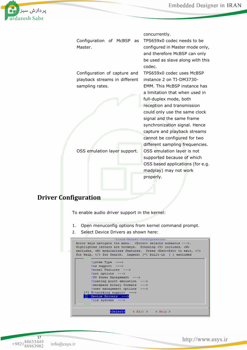
Driver Configuration
To enable audio driver support in the kernel:
1. Open menuconfig options from kernel command prompt.
2. Select Device Drivers as shown here:

18
3. Select Device Drivers > Sound card support as shown here:
4. Select Device Drivers > Sound card support > Advanced Linux
Sound Architecture as shown here:
5. Select Device Drivers > Advanced Linux Sound Architecture >
OSS PCM (digital audio) API, OSS PCM (digital audio) API –
Include plugin system (NEW) and Support old ALSA API, as
shown here:

19
6. Select Device Drivers > Sound > Advanced Linux Sound
Architecture > ALSA for SoC audio support as shown here:
7. Select Device Drivers > Sound > Advanced Linux Sound
Architecture > ALSA for SoC audio support > SoC Audio for the
Texas Instruments OMAP chips and SoC Audio support for
OMAP3 Beagle, as shown here:

20
8. To enable McBSP hardware, select System Type as shown
here:
9. Select System Type > TI OMAP Implementations as shown
here:
10. Select System Type > TI OMAP Implementations > McBSP
Support, as shown here:
21
Software Interfaces
This section provides the details of the Application Interface and
the Driver Interface for the ALSA Audio driver.
Application Interface
Application developer uses ALSA-lib, a user space library, rather
than the kernel API. The library offers 100% of the functionality of
the kernel API, but adds major improvements in usability, making
the application code simpler and better looking.
The online-documentation for the same is available at:
http://www.alsa-project.org/alsa-doc/alsa-lib/
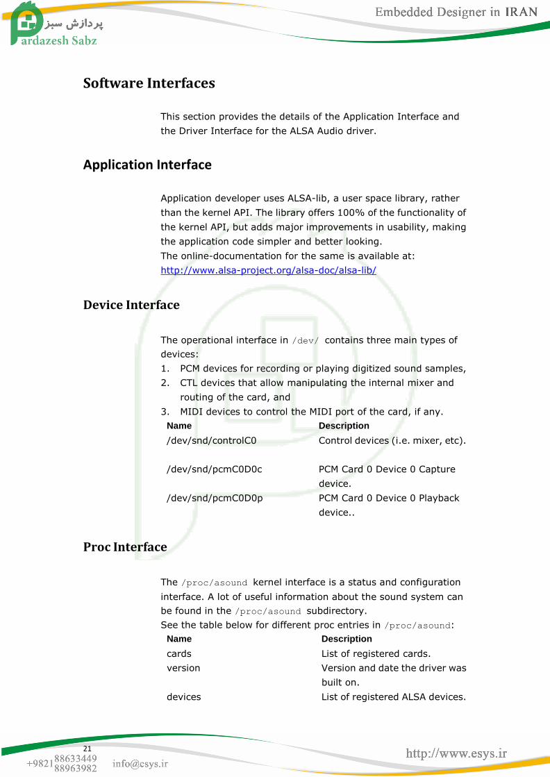
Device Interface
The operational interface in /dev/ contains three main types of
devices:
1. PCM devices for recording or playing digitized sound samples,
2. CTL devices that allow manipulating the internal mixer and
routing of the card, and
3. MIDI devices to control the MIDI port of the card, if any.
Name Description
/dev/snd/controlC0 Control devices (i.e. mixer, etc).
/dev/snd/pcmC0D0c PCM Card 0 Device 0 Capture
device.
/dev/snd/pcmC0D0p PCM Card 0 Device 0 Playback
device..
Proc Interface
The /proc/asound kernel interface is a status and configuration
interface. A lot of useful information about the sound system can
be found in the /proc/asound subdirectory.
See the table below for different proc entries in /proc/asound:
Name Description
cards List of registered cards.
version Version and date the driver was
built on.
devices List of registered ALSA devices.
22
pcm The list of allocated PCM
streams.
cardX/ (X = 0-7) The card specific directory.
cardX/pcm0p The directory of the given PCM
playback stream.
cardX/pcm0c The directory of the given PCM
capture stream.
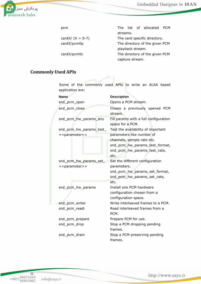
Commonly Used APIs
Some of the commonly used APIs to write an ALSA based
application are:
Name Description
snd_pcm_open Opens a PCM stream.
snd_pcm_close Closes a previously opened PCM
stream.
snd_pcm_hw_params_any Fill params with a full configuration
space for a PCM.
snd_pcm_hw_params_test_
<<parameter>>
Test the availability of important
parameters like number of
channels, sample rate etc.
snd_pcm_hw_params_test_format,
snd_pcm_hw_params_test_rate,
etc.
snd_pcm_hw_params_set_
<<parameter>>
Set the different configuration
parameters.
snd_pcm_hw_params_set_format,
snd_pcm_hw_params_set_rate,
etc.
snd_pcm_hw_params Install one PCM hardware
configuration chosen from a
configuration space.
snd_pcm_writei Write interleaved frames to a PCM.
snd_pcm_readi Read interleaved frames from a
PCM.
snd_pcm_prepare Prepare PCM for use.
snd_pcm_drop Stop a PCM dropping pending
frames.
snd_pcm_drain Stop a PCM preserving pending
frames.

23
Driver Interface
This section describes the various function entry points into the
various platform specific drivers of the audio driver.
The platform specific codec drivers are required to implement the
mentioned entry points and register with the device driver
framework by calling platform_driver_register and
platform_device_register with the appropriate data structures.
The framework calls the corresponding probe function in which the
sound card is regsitered and new PCM streams are created. The
platform specific audio driver is required to register itself with the
kernel to let the kernel know about
its availability.
Description
The platform specific ALSA audio driver is instantiated as a
'platform_driver' and is expected to implement the following
function hooks, for the core ALSA layer to probe it and handle
correctly:
codec_clock_on ()
Initializes the McBSP peripheral and the TPS659x0 audio codec.
codec_clock_off ()
Used for cleanup.
codec_configure_dev ()
Used to configure the TPS659x0 codec.
codec_set_samplerate ()
Used to set the desired sample rate.
codec_set_stereomode ()
Used to set the desired mode: mono or stereo.
Moreover, as mentioned above, while probing, the various PCM
related functions which can be performed on the actual underlying
codec are also registered via function hooks. They are codec
specific functions which will be called from the OMAP audio layer on
receiving the specific request from the user space.
Both capture and playback side PCM functions need to be
registered. Following is a list of all the functions which could be

24
implemented for a specific codec:
open
Codec initialization. The first function to be called during the
initialization of the communication paths and do the initial stuff
required for the codec to become operational. Codec is assumed to
be operational at the end of this stage.
close
Codec clean up operations are done here. This function is the last
to be called and is to be designed to request all the communication
paths to shutdown. Codec is no longer operational at the end of this
stage.
ioctl
This is used for any special action to pcm ioctls. But usually you can
pass a generic ioctl callback, snd_pcm_lib_ioctl.
hw_params
This is called when the hardware parameter (hw_params) is set up
by the application, that is, once when the buffer size, the period
size, the format, etc. are defined for the pcm substream. Many
hardware setups should be done in this callback, including the
allocation of buffers.
hw_free
This is called to release the resources allocated via hw_params.
prepare
This callback is called when the PCM is "prepared". You can set the
format type, sample rate, etc. here. The difference from
hw_params () is that the prepare callback will be called at each
time snd_pcm_prepare () is called, i.e. when recovered after
under-runs, etc.
trigger
This data transfer hook is called for transmits and receives to
send/receive data.
pointer
This data transfer hook is used to query the codec driver as to the
location of the transfer of the current buffer.

25
Sample Applications
Introduction
Writing an audio application involves the following steps:
Opening the audio device.
Set the parameters of the device.
Receive audio data from the device or deliver audio data to the
device.
Close the device.
These steps are explained in detail in this section.
Note
User space ALSA libraries can be downloaded from this link
[http://www.alsa-project.org/main/index.php/Download].
User needs to build and install them before he starts using
the ALSA based applications.
A minimal playback application
This program opens an audio interface for playback, configures it
for stereo, 16 bit, 44.1kHz, interleaved conventional read/write
access. Then its delivers a chunk of random data to it, and exits. It
represents about the simplest possible use of the ALSA Audio API,
and isn't meant to be a real program.
Opening the audio device
To write a simple PCM application for ALSA, we first need a handle
for the PCM device. Then we have to specify the direction of the
PCM stream, which can be either playback or capture. We also
have to provide some information about the configuration we
would like to use, like buffer size, sample rate, pcm data format. So,
first we declare:
#include <stdio.h>
#include <stdlib.h>

26
#include <alsa/asoundlib.h>
#define BUFF_SIZE 4096
int main (int argc, char *argv[])
{
int err;
short buf[BUFF_SIZE];
int rate = 44100; /* Sample rate */
unsigned int exact_rate; /* Sample rate returned by */
/* Handle for the PCM device */
snd_pcm_t *playback_handle;
/* Playback stream */
snd_pcm_stream_t stream = SND_PCM_STREAM_PLAYBACK;
/* This structure contains information about */
/* the hardware and can be used to specify the */
/* configuration to be used for the PCM stream. */
snd_pcm_hw_params_t *hw_params;
The most important ALSA interfaces to the PCM devices are the
"plughw" and the "hw" interface. If you use the "plughw" interface,
you need not care much about the sound hardware. If your
soundcard does not support the sample rate or sample format you
specify, your data will be automatically converted. This also applies
to the access type and the number of channels. With the "hw"
interface, you have to check whether your hardware supports the
configuration you would like to use. Otherwise, user can use the
default interface for playback by:
/* Name of the PCM device, like plughw:0,0 */
/* The first number is the number of the soundcard, */
/* the second number is the number of the device. */
static char *device = "default"; /* playback device */
Now we can open the PCM device:
/* Open PCM. The last parameter of this function is the mode.
*/
if ((err = snd_pcm_open (&playback_handle,
device, stream, 0)) < 0) {
fprintf (stderr, "cannot open audio device (%s)\n",
snd_strerror (err));
exit (1);
}
27
Setting the parameters of the device
Now we initialize the variables and allocate the hwparams
structure:
/* Allocate the snd_pcm_hw_params_t structure on the stack. */
if ((err = snd_pcm_hw_params_malloc (&hw_params)) < 0) {
fprintf (stderr, "cannot allocate hardware parameters
(%s)\n", snd_strerror (err));
exit (1);
}
Before we can write PCM data to the soundcard, we have to specify
access type, sample format, sample rate, number of channels,
number of periods and period size. First, we initialize the
hwparams structure with the full configuration space of the
soundcard:
/* Init hwparams with full configuration space */
if ((err = snd_pcm_hw_params_any (playback_handle,
hw_params)) < 0) {
fprintf (stderr, "cannot initialize hardware parameter
structure (%s)\n",
snd_strerror (err));
exit (1);
}
Now configure the desired parameters. For this example, we
assume that the soundcard can be configured for stereo playback
of 16 Bit Little Endian data, sampled at 44100 Hz. Therefore, we
restrict the configuration space to match this configuration only.
The access type specifies the way in which multi-channel data is
stored in the buffer. For INTERLEAVED access, each frame in the
buffer contains the consecutive sample data for the channels. For
16 Bit stereo data, this means that the buffer contains alternating
words of sample data for the left and right channel.
/* Set access type. */
if ((err = snd_pcm_hw_params_set_access (playback_handle,
hw_params, SND_PCM_ACCESS_RW_INTERLEAVED)) < 0) {
fprintf (stderr, "cannot set access type (%s)\n",
snd_strerror (err));

28
exit (1);
}
/* Set sample format */
if ((err = snd_pcm_hw_params_set_format (playback_handle,
hw_params, SND_PCM_FORMAT_S16_LE)) < 0) {
fprintf (stderr, "cannot set sample format (%s)\n",
snd_strerror (err));
exit (1);
}
/* Set sample rate. If the exact rate is not supported */
/* by the hardware, use nearest possible rate. */
exact_rate = rate;
if ((err = snd_pcm_hw_params_set_rate_near (playback_handle,
hw_params, &exact_rate, 0)) < 0) {
fprintf (stderr, "cannot set sample rate (%s)\n",
snd_strerror (err));
exit (1);
}
if (rate != exact_rate) {
fprintf(stderr, "The rate %d Hz is not supported by your
hardware.\n ==> Using %d Hz instead.\n", rate, exact_rate);}
/* Set number of channels */
if ((err = snd_pcm_hw_params_set_channels (playback_handle,
hw_params, 2)) < 0) {
fprintf (stderr, "cannot set channel count (%s)\n",
snd_strerror (err));
exit (1);
}
Now we apply the configuration to the PCM device pointed to by
pcm_handle and prepare the PCM device.
/* Apply HW parameter settings to PCM device and prepare
* device.
*/
if ((err = snd_pcm_hw_params (playback_handle, hw_params)) <
0) {
fprintf (stderr, "cannot set parameters (%s)\n",
snd_strerror (err));
exit (1);
}
snd_pcm_hw_params_free (hw_params);
if ((err = snd_pcm_prepare (playback_handle)) < 0) {
fprintf (stderr, "cannot prepare audio interface for use
(%s)\n", snd_strerror (err));
exit (1);

29
}
Writing data to the device
After the PCM device is configured, we can start writing PCM data
to it. The first write access will start the PCM playback. For
interleaved write access, we use the function:
/* Write some junk data to produce sound. */
if ((err = snd_pcm_writei (playback_handle, buf,
BUFF_SIZE/2)) != BUFF_SIZE/2) {
fprintf (stderr, "write to audio interface failed (%s)\n",
snd_strerror (err));
exit (1);
} else {
fprintf (stdout, "snd_pcm_writei successful\n");
}
After the PCM playback is started, we have to make sure that our
application sends enough data to the soundcard buffer. Otherwise,
a buffer under-run will occur. After such an under-run has occurred,
snd_pcm_prepare should be called.
Closing the device
After the data has been transferred, the device needs to be closed
by calling:
snd_pcm_close (playback_handle);
exit (0);
}
A minimal record application
This program opens an audio interface for capture, configures it for
stereo, 16 bit, 44.1kHz, interleaved conventional read/write
access. Then its reads a chunk of random data from it, and exits. It
isn't meant to be a real program.
Note that it is not possible to use one pcm handle for both playback
and
capture. So you have to configure two handles if you want to
access the
PCM device in both directions.

30
#include <stdio.h>
#include <stdlib.h>
#include <alsa/asoundlib.h>
#define BUFF_SIZE 4096
int main (int argc, char *argv[])
{
int err;
short buf[BUFF_SIZE];
int rate = 44100; /* Sample rate */
int exact_rate; /* Sample rate returned by */
snd_pcm_t *capture_handle;
/* This structure contains information about */
/* the hardware and can be used to specify the */
/* configuration to be used for the PCM stream. */
snd_pcm_hw_params_t *hw_params;
/* Name of the PCM device, like hw:0,0 */
/* The first number is the number of the soundcard, */
/* the second number is the number of the device. */
static char *device = "default"; /* capture device */
/* Open PCM. The last parameter of this function is
* the mode.
*/
if ((err = snd_pcm_open (&capture_handle, device,
SND_PCM_STREAM_CAPTURE, 0)) < 0) {
fprintf (stderr, "cannot open audio device (%s)\n",
snd_strerror (err));
exit (1);
}
memset(buf,0,BUFF_SIZE);
/* Allocate the snd_pcm_hw_params_t structure on the stack. */
if ((err = snd_pcm_hw_params_malloc (&hw_params)) < 0) {
fprintf (stderr, "cannot allocate hardware parameter
structure (%s)\n", snd_strerror (err));
exit (1);
}
/* Init hwparams with full configuration space */
if ((err = snd_pcm_hw_params_any (capture_handle,hw_params))
< 0) {
fprintf (stderr, "cannot initialize hardwareparameter
structure (%s)\n", snd_strerror (err));
exit (1);
}
/* Set access type. */
if ((err = snd_pcm_hw_params_set_access (capture_handle,

31
hw_params, SND_PCM_ACCESS_RW_INTERLEAVED)) < 0) {
fprintf (stderr, "cannot set access type (%s)\n",
snd_strerror (err));
exit (1);
}
/* Set sample format */
if ((err = snd_pcm_hw_params_set_format (capture_handle,
hw_params, SND_PCM_FORMAT_S16_LE)) < 0) {
fprintf (stderr, "cannot set sample format (%s)\n",
snd_strerror (err));
exit (1);
}
/* Set sample rate. If the exact rate is not supported */
/* by the hardware, use nearest possible rate. */
exact_rate = rate;
if ((err = snd_pcm_hw_params_set_rate_near (capture_handle,
hw_params, &exact_rate, 0)) < 0) {
fprintf (stderr, "cannot set sample rate (%s)\n",
snd_strerror (err));
exit (1);
}
if (rate != exact_rate) {
fprintf(stderr, "The rate %d Hz is not supported " "by your
hardware.\n ==> Using %d " "Hz instead.\n", rate, exact_rate);}
/* Set number of channels */
if ((err = snd_pcm_hw_params_set_channels(capture_handle,
hw_params, 2)) < 0) {
fprintf (stderr, "cannot set channel count (%s)\n",
snd_strerror (err));
xit (1);
}
/* Apply HW parameter settings to PCM device and
* prepare device.
*/
if ((err = snd_pcm_hw_params (capture_handle, hw_params)) < 0)
{
fprintf (stderr, "cannot set parameters (%s)\n",
snd_strerror (err));
exit (1);
}
snd_pcm_hw_params_free (hw_params);
if ((err = snd_pcm_prepare (capture_handle)) < 0) {
fprintf (stderr, "cannot prepare audio interface for use
(%s)\n", snd_strerror (err));

32
exit (1);
}
/* Read data into the buffer. */
if ((err = snd_pcm_readi (capture_handle, buf, 128)) != 128)
{
fprintf (stderr, "read from audio interface failed (%s)\n",
snd_strerror (err));
exit (1);
} else {
fprintf (stdout, "snd_pcm_readi successful\n");
}
snd_pcm_close (capture_handle);
exit (0);
}

33
Display Driver

34
Acronym Definition
V4L2 Video for Linux Two
DSS Display SubSystem
PAL
Phase Alternating Line
LCD Liquid Crystal Display
Introduction
OMAP35x display hardware integrates one graphics pipeline, two
video pipelines, and two overlay managers (one for digital and one
for analog interface). Digital interface is used for LCD and DVI
output and analog interface is used for TV out.
The primary functionality of the display driver is to provide
interfaces to user level applications and management of OMAP35x
display hardware. This includes, but is not limited to:
GUI rendering through the graphics pipeline.
Static image or video rendering through two video pipelines.
Connecting each of three pipelines to either LCD or TV output
so that the display layer is presentedon the selected output
path.
Image processing (cropping, rotation, mirroring, color
conversion, resizing, etc).
This chapter describes the driver overview along with the
supported features and constraints.
References
1. Video for Linux Two Home Page
[http://linux.bytesex.org/v4l2/]
2. Video for Linux Two API Specification
[http://v4l2spec.bytesex.org/v4l2spec/v4l2.pdf]
Acronyms & Definitions
NTSC National Television System Committee
Hardware Overview
The display subsystem provides the logic to display a video frame
from the memory frame buffer (either SDRAM or SRAM) on a

35
liquid-crystal display (LCD) panel or a TV set. The display
subsystem integrates the following elements
Display controller (DISPC) module
Remote frame buffer interface (RFBI) module
Serial display interface (SDI) complex input/output (I/O)
modulewith the associated phased-locked loop (PLL)
Display serial interface (DSI) complex I/O module and a DSI
protocolengine
DSI PLL controller that drives a DSI PLL and high-speed (HS)
divider
NTSC/PAL video encoder

36
Features
Overview
The OMAP35x Display driver supports the following features:
Supports LCD display interface at VGA resolution (480*640)
Supports TV display interface at NTSC/PAL resolutions on
Video Pipelines (both S-Video out and composite out is
supported)
Supports DVI digital interface at 720P and 480P resolution.
Supports Graphics pipeline and two video pipelines. Graphics
pipeline is supported through fbdev and video pipelines
through V4L2
Supported color formats: On OSD (Graphics pipeline):
RGB565, RGB888, ARGB and RGBA. On Video pipelines:
YUV422 interleaved, RGB565, RGB888.
Configuration of parameters such as height and width of
display screen, bits-per-pixel etc.
Supports setting up of OSD and Video pipeline destinations (TV
or LCD). Through syfs for OSD and compile time option for
video pipelines
Supports buffer management through memory mapped and
user pointer buffer exchange for application usage (mmaped)
Supports rotation - 0, 90, 180 and 270 degrees on LCD and TV
output
Supports destination and source colorkeying on Video
pipelines through V4L2
Supports alpha blending through ARGB pixel format on Video2
pipeline and RGBA and ARGB format on graphics pipeline and
global alpha blending
Usage
Usage of each feature supported by driver is explained below.
Opening and Closing of Driver
The device can be opened using open call from the application,
with the device name and mode of operation as parameters.

37
Application can open the driver only in blocking mode.
Non-blocking mode of open is not supported.
V4L2 Driver
The driver will expose two software channels (/dev/v4l/video1 and
/dev/v4l/video2), one for each video pipeline. Both of these
channels supports only blocking mode of operations. These
channels can only be opened once.
/* call to open a video Display logical channel in blocking mode
*/
video2fd_blocking =open ("/dev/v4l/video1", O_RDWR); /* closing
of channels */
close (video2fd_blocking);
FBDEV Driver
The driver will expose one software channels (/dev/fb0) for the
graphics pipeline. The driver cannot be opened multiple times.
Driver can be opened once only.
/* call to open a graphics Display logical channel in blocking
mode */
fb0fd_blocking =open ("/dev/fb0", O_RDWR); /* closing of channels
*/
close (fb0fd_blocking);
Command Line arguments
V4L2 Driver
V4L2 driver supports command line argument for specifying
default number of buffers and buffer size for both the video
pipelines. These arguments are video1_numbuffers,
video2_numbuffers, video1_bufsize and video2_bufsize. Once
number of buffers specified at the time of insertion, these many
buffers are always available until driver is removed from the
kernel.
V4L2 driver uses the VRFB buffers for rotation. Because of the
limitation of the VRFB engine these buffers are quite big in size.
Size of the VRFB buffers is listed in buffer managment section.
VRFB buffers are allocated by driver during vidioc_reqbufs ioctl if
the rotation is enabled and freed during vidioc_streamoff. But
under heavy system load memory fragmentation may occur and

38
VFRB buffer allocation may fail. To address this issue V4L2 driver
provides command line argument to allocate the VRFB buffers at
driver init time and buffers will be freed when driver is unloaded.
Command line argument is vid1_static_vrfb_alloc and
vid2_static_vrfb_alloc for video1 and video2 nodes respectively.
For dynamic build of the driver, these argument are specified at the
time of inserting the driver. For static build of the driver, these
argument can be specified along with boot time arguments.
Following example shows how to specify command line argument
for static and dynamic build.
Set the bootargsfor statically compiled driver on bootloader:
#setenv bootargs console=ttyS0,115200n8 mem=128M root=/dev/nfs
noinitrd nfsroot=172.24.190.19:nfsserver/
home,nolock,rsize=4096,wsize=4096 ip=dhcp
omap_vout.video1_numbuffers=3 omap_vout.video2_numbuffers=3
omap_vout.video1_bufsize=64400 omap_vout.video2_bufsize=64400
omap_vout.vid1_static_vrfb_alloc=y omap_vout.vid2_static_vrfb_alloc=y
mpurate=600
Note
Actual instructions and the path setting will depend upon
your shell and location of the tools
FBDEV Driver
FBDEV driver supports command line argument for
enabling/setting rotation angle, rotation type and size of vram.
These command line arguments can only be used with boot time
arguments as FBDEV driver only supports static build. Following
example shows how to specify 90 degree rotation in boot time
argument.
Set the bootargs for enabling rotation:
setenv bootargs console=ttyS0,115200n8 mem=128M noinitrd
root=/dev/nfs nfsroot=172.24.133.229:/home/user/remote/
_install,nolock,rsize=4096,wsize=4096 ip=dhcp omapfb.rotate=1
omapfb.rotate_type=1 mpurate=600

39
Following example shows how to specify size of framebuffer in boot
time argument.
Set the bootargs for specifing size of framebuffer:
Note
Actual instructions and the path setting will depend upon
your shell and location of the tools
Buffer Management
Driver Without Rotation With Rotation
FBDEV
Driver
A single buffer of size
1280*720*4*2 bytes
A single buffer of size
1280*720*4*2 bytes
V4L2
Driver
Single buffer takes
1280*720*4 bytes.
Number of buffers can
be configures using
VIDIOC_REQBUFS ioctl
and command line
argument.
Same requirement as
without rotation.
Additionally allocates one
buffer of size 1695744 bytes
for each context. Number of
context are same as the
number of buffers allocated
using REQBUFS not more
than four.
V4L2 Driver
Memory Mapped buffer mode and User pointer buffer mode are the
two memory allocation modes supported by driver.
In Memory map buffer mode, application can request memory
from the driver by calling VIDIOC_REQBUFS ioctl. In this mode,
maximum number of buffers is limited to VIDEO_MAX_FRAME
(defined in driver header files) and is limited by the available
memory in the kernel. If driver is not able to allocate the requested
number of buffer, it will return the number of buffer it is able to
allocate. The main steps that the application must perform for
buffer allocation are:

40
1) Allocating Memory
This ioctl is used to allocate memory for frame buffers. This is a
necessary ioctl for streaming IO. It has to be called for both drivers
buffer mode and user buffer mode. Using this ioctl, driver will
identify whether driver buffer mode or user buffer mode will be
used.
Ioctl: VIDIOC_REQBUFS
It takes a pointer to instance of the v4l2_requestbuffers
structure as an argument.
User can specify the buffer type (V4L2_BUF_TYPE_VIDEO_OUTPUT),
number of buffers, and memory type (V4L2_MEMORY_MMAP,
V4L2_MEMORY_USERPTR)at the time of buffer allocation. In case of
driver buffer mode, this ioctl also returns the actual number of
buffers allocated in count member of v4l2_requestbuffer
structure
It can be called with zero number of buffers to free up all the
buffers already allocated. It also frees allocated buffers when
application changes buffer exchange mechanism. Driver always
allocates buffers of maximum image size supported. If application
wants to change buffer size, it can be done through
video1_buffsize and video2_buffsize command line arguments
When rotation is enabled, driver also allocates buffer for the VRFB
virtual memory space along with the mmap or user buffer. It
allocates same number of buffers as the mmap or user buffers.
Maximum number of buffers, which can be allocated, is 4 when
rotation is enabled.
/* structure to store buffer request parameters */
struct v4l2_requestbuffers reqbuf;
reqbuf.count = numbuffers;
reqbuf.type = V4L2_BUF_TYPE_VIDEO_OUTPUT;
reqbuf.memory = V4L2_MEMORY_MMAP;
ret = ioctl(fd , VIDIOC_REQBUFS, &reqbuf);
if(ret < 0) {
printf("cannot allocate memory\n");
close(fd);
return -1;
}

41
2) Getting physical address
This ioctl is used to query buffer information like buffer size and
buffer physical address. This physical address is used in
m-mapping the buffers. This ioctl is necessary for driver buffer
mode as it provides the physical address of buffers, which are used
to mmap system call the buffers.
Ioctl: VIDIOC_QUERYBUF
It takes a pointer to instance of v4l2_buffer structure as an
argument. User has to specify the buffer type
(V4L2_BUF_TYPE_VIDEO_OUTPUT), buffer index, and memory type
(V4L2_MEMORY_MMAP)at the time of querying.
/* allocate buffer by VIDIOC_REQBUFS */
/* structure to query the physical address
of allocated buffer */
struct v4l2_buffer buffer;
/* buffer index for quering -0 */
buffer.index = 0;
buffer. type = V4L2_BUF_TYPE_VIDEO_OUTPUT;
buffer.memory = V4L2_MEMORY_MMAP;
if (ioctl(fd, VIDIOC_QUERYBUF, &buffer) < 0) {
printf("buffer query error.\n");
close(fd);
exit(-1);
}
/*The buffer.m.offset will contain the physical address returned
from driver*/
3) Mapping Kernel space address to user space
Mapping the kernel buffer to the user space can be done via mmap.
User can pass buffer size and physical address of buffer for getting
the user space address
/* allocate buffer by VIDIOC_REQBUFS */
/* query the buffer using VIDIOC_QUERYBUF */
/* addr hold the user space address */
unsigned int addr;
Addr = mmap(NULL, buffer.size,PROT_READ | PROT_WRITE, MAP_SHARED,
fd, buffer.m.offset);
/* buffer.m.offset is same as returned from VIDIOC_QUERYBUF */

42
FBDEV Driver
FBDEV driver supports only memory mapped buffers. If rotation is
not enabled at the time of insertion of the driver, it allocates one
physically contiguous buffers, which can support 640X480
resolution for all buffer formats supported. If rotation is enabled,
driver allocates single buffer of maximum resolution for the VRFB
memory space. Following steps are required to map buffers in
application memory space
1) Getting fix screen information
FBIOGET_FSCREENINFO ioctl is used to get the not-changing
screen information like physical address of the buffer, size of the
buffer, line length.
/* Getting fix screen information */
struct fb_fix_screeninfo fix;
ret = ioctl(display_fd, FBIOGET_FSCREENINFO, &fix);
if(ret < 0) {
printf("Cannot get fix screen information\n");
exit(0);
}
printf("Line length = %d\n",fix.line_length);
printf("Physical Address = %x\n",fix.smem_start);
printf("Buffer Length = %d\n",fix.smem_len);
2) Getting Variable screen information
FBIOGET_VSCREENINFO ioctl is used to get the variable screen
information like resolution, bits per pixel etc.
/* Getting fix screen information */
struct fb_var_screeninfo var;
ret = ioctl(display_fd, FBIOGET_VSCREENINFO, &var);
if(ret < 0) {
printf("Cannot get variable screen information\n");
exit(0);
}
printf("Resolution = %dx%d\n",var.xred, var.yres);
printf("bites per pixel = %d\n",var.bpp);
3) Mapping Kernel space address to user space
Mapping the kernel buffer to the user space can be done via mmap
system call.
/* addr hold the user space address */
unsigned int addr, buffersize;

43
/* Get the fix screen info */
/* Get the variable screen information */
buffersize = fix.line_length * var.yres;
addr = mmap(NULL, buffersize, PROT_READ | PROT_WRITE, MAP_SHARED,
fd, 0);
/* buffer.m.offset is same as returned from VIDIOC_QUERYBUF */
Rotation
Rotation is implemented with use of Rotation Engine module in
Virtual Rotation Frame Buffer module in OMAP35X. Rotation engine
supports rotation of an image with degree 0, 90, 180 and 270.
There are 12 contexts available for rotating an image and there are
four virtual memory space associated with each context. To rotate
an image, image is written to 0 degree virtual memory for a
context and rotated image can read back from the virtual memory
for that angle of the same context.
For using Rotation Engine, User has to allocate physical memory
and provide address of the memory to the rotation engine. The
buffer size for this physical buffer should be large enough to store
the image to be rotated. When program writes to the virtual
address of the context, rotation engine write to this memory space
and when program reads image from virtual address, rotation
engine reads image from this buffer with rotation angle.
V4L2 Driver
V4L2 driver supports rotation by using rotation engine in the VRFB
module. Driver allocates physical buffers, required for the rotation
engine, when application calls VIDIOC_REQBUFS ioctl. Therefore,
when this ioctl is called driver allocates buffers for storing image
and allocates buffers for the rotation engine. It also programs
VRFB rotation engine when this ioctl is called. At the time of
enqueing memory mapped buffer, driver copies entire image from
mmaped buffer to buffer for the rotation engine using DMA. DSS is
programmed to take image from VRFB memory space when
rotation is enabled. So DSS always gets rotated image. Maximum
four buffers can be allocated using REQBUFS ioctl when rotation is
enabled.
Driver provides ioctl interface for enabling/disabling and changing
the rotation angle. These ioctls are
VIDIOC_S_CTRL/VIDIOC_G_CTRL as drive allocates buffer for

44
VRFB during REQBUFS ioctl, application has to enable/set the
rotation angle before calling REQBUFS ioctl. After enabling rotation,
application can change the rotation angle. Rotationangle cannot be
changed while streaming is on. Following code shows how to set
rotation angle to 90 degree.
Important
Rotation value must be set using VIDIOC_S_CTRL before
setting any format using VIDIOC_S_FMT as VIDIOC_S_FMT
uses rotation value for calculating buffer formats. Also
VIDIOC_S_FMT ioctl must be called after changing the
rotation angle to change parameters as per the new rotation
angle
struct v4l2_control control;
int degree = 90;
control.id = V4L2_CID_ROTATION;
control.value = degree;
ret = ioctl(fd, VIDIOC_S_CTRL, &control);
if (ret < 0) {
perror("VIDIOC_S_CTRL\n");
close(fd);
exit(0);
}
/* Rotation angle is now set to 90 degree. Application can now
do streaming to see rotated image*/
FBDEV Driver
FBDEV driver supports rotation by using rotation engine in the
VRFB module. For using this feature of the driver, rotation has to
be enabled. Application can enable rotation by enabling/setting
rotation angle in boot time argument of the kernel for FBDEV driver.
One of the fields in the fb_var_screeninfo structure has been used
for 'rotate' field. Applications can thus use the
FBIOPUT_VSCREENINFO ioctl to set the rotation angle.
Applications have to set this 'rotate' field in the fb_var_screeninfo
structure equal to the angle of rotation (0, 90, 180 or 270) and call
this ioctl. Frame buffer driver also supports the rotation through
sysfs entry. Any one of the two method can be used to configure
rotation.
Constraint: While doing rotation x-resolution virtual should be
equal to x-resolution. y-resolution virtual should be greater than or

45
equal to y resolution. Please note that VRFB rotation engine
requires alignment of 32 bytes in horizontal size and 32 lines in
vertical size. So while doing rotation x-resolution should be 32 byte
aligned and y resolution and y resolution virtual should be 32 lines
aligned. For example for 360X360 required resolution with 16bpp
no of bytes per line comes to 360*2=720. Which is not 32 byte
aligned. While no of lines comes to 360 which is also not 32 lines
aligned. So actual resolution should be set to 368X368. But if same
resolution is required for 32bpp then no of bytes per line comes to
360*4 that is 1440. Which is 32 byte aligned so actual resolution
should be set to 360X368. Also the maximum y-res virtual possible
is 2048 because of VRFB limitation when rotation enabled.
Important
FBDEV driver internally reverses/manages the xres and yres
for the 90 and 270 degree rotation, so user must give original
values for rotation. var.rotate variable should not be
modified when rotation is not selected through command
line arguments else behaviour is unexpected.
Important
By default frame buffer driver allocates the buffer for single
720P frame considering 0 degree rotation.
This allocation can be overridden using the command line
arguments
"vram= and omapfb.vram="
Memory requirement can be calculated by following
equation (2048 * yres_virtual * max_Bpp)* NO_OF_BUFFERS,
2048 is the default pitch required by VRFB, yres_virtual =
maximum virtual yresolution required, max_Bpp = maximum
bytes per pixel required, NO_OF_BUFFERS = Number of
buffers required for panning.
So for 720*1280 resolution with 32bpp with two buffers with
90 or 270 degree rotation it comes to (2048 * 1280 * 4) * 2 =
20971520 bytes which rounds upto 20M bytes. so above
command line arguments will look like
"vram=20M omapfb.vram=20M"
So it is not desirable to have panning for 720P resolution.
For 480P it comes to (2048 * 720 * 4) * 2 which is equal to

46
11796480 bytes with rounding up it is 12M bytes.
Rotation is supported for 16bpp, 24 unpacked bpp and 32 bpp.
Rotation can be enabled by using "omapfb.rotate=1" and
"omapfb.rotate_type=1" boot time argument given to the boot
loader. Enabling rotation by setting rotation angle of 90 degree.
Value of omapfb.rotate can be 0, 1, 2 or 3 where 0 = 0 degree, 1 =
90 degree, 2 = 180 degree and 3 = 270 degree.
Following code listings demos how to set the rotation in frame
buffer driver using ioctl and sysfs entry.
struct fb_var_screeninfo var;
/* Set the rotation through ioctl. */
/* Get the Variable screen info through "FBIOGET_VSCREENINFO" */
var.rotate = 1; /* To set rotation angle to 90 degree */
if (ioctl(fb, FBIOPUT_VSCREENINFO, &var)<0) {
perror("Error:FBIOPUT_VSCREENINFO\n");
exit(4);
}
Setting the rotation through sysfs where 0 - 0 degree, 1 - 90
degree, 2- 180 degree and 3 - 270 degree respectively
Buffer Format
Buffer format describes the pixel format in the image. It also
describes the memory organization of each color component within
the pixel format. In all buffer formats, blue value is always stored
in least significant bits, then green value and then red value.
V4L2 Driver
Video layer supports following buffer format: YUYV, UYVY, RGB565,

47
RGB24 (packed and unpacked). The corresponding v4l2 defines for
pixel format are V4L2_PIX_FMT_YUYV, V4L2_PIX_FMT_UYVY,
V4L2_PIX_FMT_RGB565, V4L2_PIX_FMT_RGB24(packed),
V4L2_PIX_FMT_RGB32. (For video1 and video2
V4L2_PIX_FMT_RGB32 corresponds to RGB24 unpacked). Buffer
format can be changed using VIDIOC_S_FMT ioctl with type as
V4L2_BUF_TYPE_VIDEO_OUTPUT and appropriate pixel format
type. Following example shows how to change pixel format to
RGB565
struct v4l2_format fmt;
fmt.type = V4L2_BUF_TYPE_VIDEO_OUTPUT;
fmt.fmt.pix.pixelformat = V4L2_PIX_FMT_RGB565;
ret = ioctl(fd, VIDIOC_S_FMT, &fmt);
if (ret < 0) {
perror("VIDIOC_S_FMT\n");
close(fd);
exit(0);
}
FBDEV Driver
Graphics layer supports following buffer format: RGB24(un-packed)
and RGB565. Buffer format can be changed in FBDEV driver by
using bpp, red, green, and blue fields of fb_vscreeninfo structure
and ioctl FBIOPUT_VSCREENINFO. Application needs to specify
bits per pixel and length and offset of red, green and blue
component. Bits-per-pixel and color depth in the pixel aren't quite
the same thing. The display controller supports color depths of 1, 2,
4, 8, 12, 16, 24 and 32 bits. Color depth and bits-per-pixel are the
same for depths of 1, 2, 4, 8, and 16 bits, but for a color depth of
12 bits the pixel data is padded to 16 bits-perpixel, and for a color
depth of 24 bits the pixel data is padded to 32 bitsper-pixel. So
application has to specify bits per pixel 16 and 32 for the color
depth 12 and 24. To specify exact color depth, red, green and blue
member of the fb_varscreeninfo can be used. Following example
shows how to set 12 and 24 bits per pixels.
Struct fb_varscreeninfo var;
var.bpp = 16;
var.red.length = var.green.length = var.blue.length = 4;
var.red.offset = 8;
var.green.offset = 4;
var.blue.offset = 0;
ret = ioctl(fd, FBIOPUT_VSCREENINFO, &var);

48
if (ret < 0) {
perror("FBIOPUT_VSCREENINFO\n");
close(fd);
exit(0);
}

49
Architecture
This chapter describes the Driver Architecture and Design concepts
Driver Architecture
OMAP35x display hardware integrates one graphics pipeline, two
video pipelines, and two overlay managers (one for digital and one
for analog interface). Digital interface is used for LCD and DVI
output and analog interface is used for TV out.
The primary functionality of the display driver is to provide
interfaces to user level applications and management to OMAP35x
display hardware.This includes, but is not limited to:
GUI rendering through the graphics pipeline.
Static image or video rendering through two video pipelines.
Connecting each of three pipelines to either LCD or TV output
so the display layer is presented on the selected output path.
Image processing (cropping, rotation, mirroring, color
conversion, resizing, and etc).
Software Design Interfaces
Above figure shows the major components that makes up the DSS
software sub-system
Display Library
This is a HAL/functional layer controlling the bulk of DSS hardware.
It exposes the number of APIs controlling the overlay managers,
clock, and pipelines to the user interface drivers like V4L2 and
FBDEV.
It also exposes the functions for registering and de-registering of
the various display devices like LCD and DVI to the DSS overlay
managers.
SYSFS interfaces
The SYSFS interfaces are mostly used as the control path for
configuring the DSS parameters which are common between
FBDEV and V4L2 like the panel size, pixel clock frequency, alpha
blending etc.
It is also used for switching the output of the pipeline to either LCD
or Digital overlay manager. In future sysfs entries might also be

50
used to switch the modes like NTSC, PAL on TV and 480P, 720P on
DVI outputs.
Note
Please note that due to clock source limitation while
switching the output DSS2 throws error message "Could not
find exact pixel clock" (In order to fix this we need to use DSI
input clock source).
Frame Buffer Driver
This driver is registered with the FBDEV subsystem, and is
responsible for managing the graphics layer frame buffer. Driver
creates /dev/fb0 as the device node. Application can open this
device node to open the driver and negotiate parameters with the
driver through frame buffer ioctls. Application maps driver
allocated buffers in the application memory space and fills them for
the driver to display.
Video Applications & V4L2 subsystem
Video applications (camera, camcorder, image viewer, etc.) use
the standard V4L2 APIs to render static images and video to the
video layers, or capture/preview camera images.
This driver is responsible for managing the video layers' frame
buffers. It is a V4L2 compliant driver with some additions to
implement special software requirements that target OMAP35x
hardware features. This driver conforms to the Linux driver model.
For using the driver, application should create the device nodes
/dev/v4l/video1and /dev/v4l/video2device nodes for two
video layers. Application can open the driver by opening these
device nodes and negotiate the parameters by V4L2 ioctls. Initially
application can request the driver to allocate number of buffers and
MMAPs these buffers. Then the application can fill up these buffers
and pass them to driver for display by using the standard V4L2
streaming ioctls.

51
Software Interfaces
'fbdev' Driver Interface
Application Interface
open ()
To open a framebuffer device
close ()
To close a framebuffer device
ioctl ()
To send ioctl commands to the framebuffer driver.
mmap ()
To obtain the framebuffer region as mmap'ed area in user space.
Supported Standard IOCTLs
FBIOGET_VSCREENINFO, FBIOPUT_VSCREENINFO
These I/O controls are used to query and set the so-called variable
screen info. This allows an application to query or change the
display mode, including the color depth, resolution, timing etc.
These I/O controls accept a pointer to a struct fb_var_screeninfo
structure. The video mode data supplied in the fb_var_screeninfo
struct is translated to values loaded into the display controller
registers.
FBIOGET_FSCREENINFO
This I/O control can be used by applications to get the fixed
properties of the display, e.g. the start address of the framebuffer
memory. This I/O control accepts a pointer to a struct
fb_fix_screeninfo
FBIOGETCMAP, FBIOPUTCMAP
These I/O controls are used to get and set the color-map for the
framebuffer. These I/O controls accept a pointer to a struct
fb_cmap structure.
FBIO_BLANK

52
This I/O control is used to blank or unblank the framebuffer
console.
Data Structures
fb_var_screeninfo
This structure is used to query and set the so-called variable screen
information. This allows an application to query or change the
display mode, including the color depth, resolution, timing etc.
fb_fix_screeninfo
This structure is used by applications to get the fixed properties of
the display, e.g. the start address of the framebuffer memory,
framebuffer length etc.
fb_cmap
This structure is used to get/set the color-map for the framebuffer
V4L2 Driver Interface
Application Interface
open
To open a video device
close
To close a video device
ioctl
To send ioctl commands to the display driver.
mmap
To memory map a driver allocated buffer to user space
Supported Standard IOCTLs

53
Note
This section describes the standard V4L2 IOCTLs supported
by the Display Driver. Standard IOCTLs that are not listed
here are not supported. The Display Driver handles the
unsupported ones by returning EINVAL error code.
VIDIOC_QUERYCAP
This is used to query the driver's capability. The video driver fills a
v4l2_capability struct indicating the driver is capable of output and
streaming.
VIDIOC_ENUM_FMT
This is used to enumerate the image formats that are supported by
the driver. The driver fills a v4l2_fmtdesc struct.
VIDIOC_G_FMT
This is used to get the current image format or display window
depending on the buffer type. The driver fills the information to a
v4l2_format
struct.
VIDIOC_TRY_FMT
This is used to validate a new image format or a new display
window depending on the buffer type. The driver may change the
passed values if they are not supported. Application should check
what is granted.
VIDIOC_S_FMT
This is used to set a new image format or a new display window
depending on the buffer type. The driver may change the passed
values if they are not supported. Application should check what is
granted if VIDIOC_TRY_FMT is not used first.
VIDIOC_CROPCAP
This is used to get the default cropping rectangle based on the
current image size and the current display panel size. The driver
fills a v4l2_cropcap struct.
VIDIOC_G_CROP
This is used to get the current cropping rectangle. The driver fills a
v4l2_crop struct.
VIDIOC_S_CROP

54
This is used to set a new cropping rectangle. The driver fills a
v4l2_crop struct. Application should check what is granted.
VIDIOC_REQBUFS
This is used to request a number of buffers that can later be
memory mapped. The driver fills a v4l2_requestbuffers struct.
Application should check how many buffers are granted.
VIDIOC_QUERYBUF
This is used to get a buffer's information so mmap can be called for
that buffer. The driver fills a v4l2_buffer struct.
VIDIOC_QBUF
This is used to queue a buffer by passing a v4l2_buffer struct
associated to that buffer.
VIDIOC_DQBUF
This is used to dequeue a buffer by passing a v4l2_buffer struct
associated to that buffer.
VIDIOC_STREAMON
This is used to turn on streaming. After that, any VIDIOC_QBUF
results in an image being rendered.
VIDIOC_S_CTRL VIDIOC_G_CTRL VIDIOC_QUERYCTRL
These ioctls are used to set/get and query various V4L2 controls
like rotation, mirror and background color. Currently only rotation
is supported
VIDIOC_STREAMOFF
This is used to turn off streaming.
SYSFS Software Design Interfaces
Currently we are not supporting the sysfs interfaces for functions
like changing the output, changing the mode and alpha blending.
But bulk of sysfs entries are exported by DSS library. Please refer
to the Migration guide for detailed explanation on sysfs entries
supported.
Note
This section describes the standard V4L2 IOCTLs supported
by the Display Driver. Standard IOCTLs that are not listed
here are not supported. The Display Driver handles the
unsupported ones by returning EINVAL error code.

55
Driver Configuration
Configuration Steps
To enable V4L2 video driver:
1. Open menuconfig options from kernel command prompt.
2. Select Device Drivers as shown here:
3. Select Device Drivers > Multimedia devices as shown here:
4. Select Video For Linux

56
5. Select Device Drivers > Multimedia devices > Video capture
adapaters as shown here and go inside the main menu:
6. Select OMAP2/OMAP3 V4L2-DSS Drivers. Select Video out
library Video out driver support under OMAP2/OMAP3
V4L2-DSS Drivers

57
To enable Frame buffer driver.
1. Open menuconfig options from kernel command prompt.
2. Select Device Drivers as shown here:
3. Select Device Drivers > Graphics Supports as shown here:
4. Select Support for frame buffer devices under Graphics
support as shown.

58
Installation
5. Select OMAP2/3 Frame buffer support (EXPERIMENTAL) and 1
as Number of Frame buffers. Select 1 will allow the Graphics
pipeline of the DSS to be controlled by FBDEV interface and
both video pipelines by V4L2 interface. Selecting 2 will allow
graphic pipeline and 1 video pipeline to be controlled by FBDEV
interface and one video pipeline by V4L2 interface. Selecting 3
will allow all the three DSS pipelines to be controlled by FBDEV
interface.
Driver built statically
If the v4l2 video driver is built statically into the kernel, it is
activated during boot-up. If frame buffer driver is built statically it
gets activated during bootup. Modular build of frame buffer is not
supported.
Driver built as loadable module
If the video driver and video library has been configured to be a
loadable modules, then the driver are built as a modules with the
name omap_vout.ko and omap_voutlib.ko, which will be placed
under directory drivers/media/video/omap/ in the kernel tree.
Copy this driver files on to the target board and issue the following
command to insert the driver:

59
insmod omap_vout.ko
insmod omap_voutlib.ko
There might be some dependencies for this module on other
modules, These modules also need to be inserted before inserting
V4L2 video driver.
To remove the driver, issue the following command:
rmmod omap_vout.ko
rmmod omap_voutlib.ko

60
USB Driver

61
Introduction
TI OMAP35x has a host cum gadget controller MUSB OTG,an EHCI
and its companion OHCI controller.There are three USB ports
which are to be controlled by either EHCI or OHCI controller
individually. In ES2.0/2.1 silicon all the three port can either be
configured in PHY mode or in TLL mode at a time.This limitation got
resolved in ES3.0/3.1 silicon where PHY/TLL mode selection can be
done on per port basis.
The salient features of the MUSB OTG controller are:
High/full speed operation as USB peripheral.
High/full/low speed operation as Host controller.
The host controller for a multi-point USB system (when
connected via hub).
USB On-The-Go compliant USB controller.
15 Transmit and 15 Receive Endpoints other than the
mandatory Control Endpoint 0.
16 Kilobytes of Endpoint FIFO RAM for USB packet buffering.
Double buffering FIFO.
Support for Bulk split and Bulk combine
Support for high bandwidth Isochronous transfer
Dual Mode HS DMA controller with 8 channels.
References
1. OMAP35x Technical Reference Manual
Hardware Overview
The OMAP35x MUSB OTG controller sits on the L3 and L4
interconnect. It can be an L3 master while performing DMA
transfers and an L4 target when host CPU/DMA engine is the
master.
The USB controller in the SoC is connected to the TPS659x0 USB
PHY located on the EV-C. A mini-AB USB port connects to the PHY.
Hence, there is only one root port for the USB controller.
62
Features
The MUSB OTG and EHCI drivers supports a significant subset of all
the features provided by the USB controller. The following section
discusses the supported and unsupported features in this release.
Supported
The Driver supports the following features for MUSB OTG port:
Can be built in-kernel (part of vmlinux) as well as a driver
module (musb_hdrc.ko).
Audio Class in Host mode.
Video Class in Host mode.
Mass Storage Class in Host mode.
Mass Storage Class in Gadget mode.
Hub Class in Host mode.
Human Interface Devices (HID) in Host mode.
Communication Device Class (CDC) in Gadget mode.
Remote Network Driver Interface Specification (RNDIS)
Gadget support.
OTG support which includes support for Host Negotiation
Protocol (HNP) and Session Request Protocol (SRP).
Limitations
Driver doesn't behave as expected when power management
is enabled.

63
Driver configuration
The MUSB OTG controller is used in Host and Gadget modes while
EHCI is used only in Host mode.The following section shows the
configuration options for USB and its associated class drivers.
USB phy selection for MUSB OTG port
Please select NOP USB transceiver for MUSB support.
USB controller in host mode
MUSB OTG Host Configuration

64
MUSB OTG controller in gadget mode
Configuration
Please do not disable support for host side usb as this will disable
EHCI host interface also.Gadget option in driver mode will appear
only when gadget support is also selected.
MUSB OTG controller in OTG mode
OTG Configuration
Both Host and Gadget driver should be selected for OTG support. If
gadget driver is build as module then the host side module will be
initialized only after gadget module is inserted after bootup.
If "Rely on targeted peripheral list" is also selected then make sure
to update "drivers/usb/core/otg_whitelist.h" with the desired
supported device class identification ids.
OTG option in driver mode will appear only when gadget support is
also selected. Please make sure that Inventra HDRC is selected as
USB peripheral controller which will appear only when OTG is
selected.

65
Software Interface
The USB driver exposes its state/control through the sysfs and the
procfs interfaces. The following sections talks about these.
sysfs
SYSFS attribute Description
mode The entry
/sys/devices/platform/musb_hdrc.0/mode
is a read-only entry. It will show the state of
the OTG (though this feature is not
supported) state machine. This will be true
even if the driver has been compiled without
OTG support. Only the states like A_HOST,
B_PERIPHERAL, that makes sense for
non-OTG will show up.
vbus The entry
/sys/devices/platform/musb_hdrc.0/vbus
is a write-only entry. It is used to set the
VBUS timeout value during OTG. If the
current OTG state is a_wait_bcon then then
urb submission is disabled.
procfs
The profcs entry /proc/driver/musb_hdrc is used to control the
driver behaviour as well as check the status of the driver. The
following command will show the usage of this proc entry
$ echo "?" > /proc/driver/musb_hdrc
Specifically the most important usage of this entry would be to
start an USB session(host mode) by issuing the following
command:
$ echo "F" > /proc/driver/musb_hdrc

66
MMC Driver
67
Introduction
TI OMAP 35x has an multimedia card high-speed/secure
data/secure digital I/O (MMC/SD/SDIO) host controller, which
provides an interface between microprocessor and either MMC, SD
memory cards, or SDIO cards. The current version of the user
guide talks about the MMC/SD controller. The MMC driver is
implemented on top of host controller as a HSMMC controller driver
and supports MMC, SD, SD High Speed and SDHC cards. The
salient features of the aforementioned HSMMC host controller are:
Full compliance with MMC/SD command/response sets as
defined in the Specification.
Support:
• 1-bit or 4-bit transfer mode specifications for SD and SDIO
cards
• 1-bit, 4-bit, or 8-bit transfer mode specifications for MMC
cards
Built-in 1024-byte buffer for read or write
32-bit-wide access bus to maximize bus throughput
Single interrupt line for multiple interrupt source events
Two slave DMA channels (1 for TX, 1 for RX)
Designed for low power and Programmable clock generation
References
1. MMCA Homepage [http://www.mmca.org/home]
2. SD ORG Homepage [http://www.sdcard.org/home]
Acronyms & Definitions
Acronym Definition
MMC Multimedia card
HSMMC High Speed MMC
SD Secure Digital
SDHC SD High Capacity
SDIO SD Input/Output

68
Features
Features Supported
The Driver supports the following features:
The driver is built in-kernel (part of vmlinux).
MMC cards including High Speed cards.
SD cards including SD High Speed and SDHC cards.
Uses block bounce buffer to aggregate scatterred blocks
Features Not Supported
The following features are not currently supported by driver:
SDIO functionality is not supported.
MMC 8-bit mode is not supported.
MMC/SD cards cannot be removed while mount operation is in
progress. If the card is removed, data integrity cannot be
guaranteed.
Limitations
The driver sometimes reports CRC error during read because
of hardware issue.

69
Power Management

70
Introduction
OMAP35x silicon provides a rich set of power management
features. These features are described in detail in the OMAP35x
TRM.
In summary:
Clock control at the module and clock domain level.
16 power domains i.e. 16 sets of one or more hardware
modules sharing same power source.
Control of scalable voltage domains.
Independent scaling of OPPs for the VDD1 and VDD2. MPU and
IVA (in case of OMAP3530) share the voltage domain VDD1.
Other modules are located in VDD2.
Support for transitioning power and voltage domains to
retention/off and wakeup on event.
References
1. Proceedings of the Linux Symposium, June 27-30, 2007
[http://ols.108.redhat.com/2007/Reprints/pallipadi-Reprint.p
df]
Authors: Venkatesh Pallipadi, Shaohua Li, Adam Belay

71
Features
The power management features available in this release are
based on the proposed PM interface for OMAP. This interface is
described in the filename Documentation/arm/OMAP/omap_pm.
Supported
This is list of features supported in this release:
Supports Dynamic Tick framework.
Supports the cpuidle framework with MPU and Core transition
to RETENTION and OFF states. The menu governor is
supported.
Basic implementation for cpufreq.
Support SmartReflex with automatic (hardware-controlled)
mode of operation.
Not Supported
This is list of features not supported in the current release:
Allow drivers and applications to limit the idle state that can be
entered.
Support for SmartReflex with manual (software-controlled)
mode of operation.
Limitations
This is list of limitations that exist in the current release:
Some of the drivers do not leverage the power-saving features
supported by the silicon.
They need to enable/ disable corresponding clocks via
clk_enable() and clock_disable() only when the clocks are
really needed.
After the system is suspended, the resume operation does not
succeed from the keypad and touchscreen.

72
Architecture
cpuidle
The cpuidle framework consists of two key components:
A governor that decides the target C-state of the system.
A driver that implements the functions to transition to target
C-state.
System Diagram
The idle loop is executed when the Linux scheduler has no thread
to run. When the idle loop is executed, current 'governor' is called
to decide the target C-state. Governor decides whether to continue
in current state/transition to a different state. Current 'driver' is
called to transition to the selected state.
C-states
A C-state is used to identify the power state supported through the
cpu idle loop. Each C-state is characterized by its:
Power consumption
Wakeup latency
Preservation of processor state while in 'the' state.
The definition of C-states in the OMAP3 are a combination of the
MPU and CORE states. Currently these C-states have been defined:

73
State Description
C1 MPU WFI + Core active
C2 MPU WFI + Core inactive
C3 MPU CSWR + Core inactive
C4 MPU OFF + Core inactive
C5 MPU RET + CORE RET
C6 MPU OFF + CORE RET
C7 MPU OFF + CORE OFF
CPU Idle Governor
The current implementation supports the 'menu' governor to
decide the target C-state of the system.
CPU Idle Driver
The cpuidle driver registers itself with the framework during
boot-up and populates the C-sates with exit latency, target
residency (minimum period for which the state should be
maintained for it to be useful) and flag to check the bus activity.
In ACPI implementation, flag CPUIDLE_FLAG_CHECK_BM is used to
specify the states requiring bus monitoring interface to be checked.
In the OMAP3 implementation, this flag is used to identify the
C-states that require CORE domain activity to be checked.
Once the governor has decided the target C-state, the control
reaches the function omap3_enter_idle(). Here, the C-state is
adjusted based on the value of valid flag corresponding to the
chosen state.
Note
The value of valid flag for the idle states relates to
/sys/power/enable_off_mode. If transition to OFF mode is
disabled, the idle states that require MPU to be turned OFF
are made valid.

74
Performance considerations
Once idle power management is enabled, the system will transition
across sleep states of varying latency. This transition can impact
the runtime performace of the drivers.
The current implementation does not support any mechanism to
prevent the idle state transitions. However, function pair
omap2_block_sleep() and omap2_allow_sleep() can be used to
prevent transitions away from the C1 state.
Important
Functions omap2_block_sleep() and
omap2_allow_sleep() should be used to protect idle state
transition in a controlled and narrow scope - where driver is
doing real work. Else, power consumption will increase.
Dynamic Tick Suppression
The dynamic tick suppression is achieved through generic Linux
framework for the same.
A 32K timer (HZ=128) is used by the tick suppression algorithm.
Suspend & Resume
The suspend operation results in the system transitioning to the
lowest power state being supported.
The drivers implement the suspend() function defined in the LDM.
When the suspend for the system is asserted, the suspend()
function is called for all drivers. The drivers release the clocks to
reach the desired low power state.
The actual transition to suspend is implemented in the function
omap3_pm_suspend().

75
Configuration
To enable/ disable power management start the Linux Kernel
Configuration tool.
Select Power management options from the main menu.
Select Power Management support to toggle the power management
support.
cpuidle
Select CPU Power Management from the main menu.

76
Select CPU idle PM support to enable the cpuidle driver.

77
cpufreq
SmartReflex
Select CPU Power Management from the main menu. Select CPU idle
PM support to enable the cpuidle driver.
Select System Type from the main menu.
Select TI OMAP Implementations from the menu.

78
Select SmartReflex support from the menu.

79
Software Interface
The cpuidle framework defines a standard interface through /sys
interface.
cpuidle
The parameters controlling cpuidle can be viewed via via /sys
interface.
$ ls -1 /sys/devices/system/cpu/cpuidle/
current_driver
current_governor_ro
current_governor_ro lists the current governor.
$ cat /sys/devices/system/cpu/cpuidle/current_governor_romenu
current_driver lists the current driver.
$ cat
/sys/devices/system/cpu/cpuidle/current_driveromap3_idle
The cpuidle interface also exports information about each idle state.
This information is organized in a directory corresponding to each
idle state.
$ ls -1 /sys/devices/system/cpu/cpu0/cpuidle
state0
state1
state2
state3
state4
state5
state6

80
$ ls -1 /sys/devices/system/cpu/cpu0/cpuidle/state0
desc
latency
name
power
time
usage
Idle state transition
To allow/prevent the processor to enter idle states, execute these
commands:
$ echo 1 > /sys/power/sleep_while_idle
$ echo 0 > /sys/power/sleep_while_idle
Some of the clocks are not explicitly enabled and disabled on idle.
To allow these clocks to be enabled/ disabled execute these
commands:
$ echo 1 > /sys/power/clocks_off_while_idle
$ echo 0 > /sys/power/clocks_off_while_idle
To allow/ prevent transition to OFF mode:
$ echo 1 > /sys/power/enable_off_mode
$ echo 0 > /sys/power/enable_off_mode
Suspend & Resume
The suspend for device can be asserted as follows:
$ echo -n "mem" > /sys/power/state
To wakeup, press a key on the OMAP3EVM keypad; or tap any on

81
the serial console.
SmartReflex
To enable/ disable SmartReflex for VDD1:
$ echo 1 > /sys/power/sr_vdd1_autocomp
$ echo 0 > /sys/power/sr_vdd1_autocomp
T
To enable/ disable SmartReflex for VDD2:
$ echo 1 > /sys/power/sr_vdd2_autocomp
$ echo 0 > /sys/power/sr_vdd2_autocomp

82
Release Note

83
This release notes provides important information that will assist
you in using the OMAP35x EVM Linux PSP. This document contains
product information and known issues that are specific to the Linux
PSP for the OMAP35x EVM.
The PSP Package serves to provide a fundamental software
platform for development, deployment and execution. This
abstracts the functionality provided by the hardware. The product
forms the basis for all application development on this platform.
Important
This release is based on open source Linux Kernel Version
2.6.29-rc3.
(commit-id :c40ce00e32082c57070fdba39c7d7cba3228d440).
It has been tested on the TI-DM3730-EM-C (Rev A3) with the
ES3.1 processor.

84
Video
Display
linux-omap git supports only minimal fbdev driver
(no V4L2 support). This release is based on the
DSS2 library and frame buffer driver submitted by
Tomi to the community
(http://www.bat.org/~tomba/git/linux-omap-dss.git).
The release includes enhancements/fixes to the
DSS2 library and fbdev driver (support for rotation,
wait_for_vsync, dvi, argb). Also included in the
release is the V4L2 driver, built around the DSS2
library. All patches are under various stages of
submission/review/acceptance and can change in
the future.
Audio Driver This release includes patches (posted for
community review) that add support for EMA3530
EVM under ASOC.
Power
Management
Power management support is based on work
from "pm" branch of linux-omap git (PM changes
not on "master" branch yet). Patches from the pm
branch are merged against the chosen kernel
baseline and tested with other drivers. Further
fixes/enhancements included in the release
package have been submitted back to the
community.
USB Includes patches that have submitted/accepted in
the community (linux-usb git). These patches have
been ported against the release baseline.
Note
The linux-omap git does not include full support for Video/PM
Subsystems. It was expected that most of the Video/PM
functionality will be rolled into linux-omap git by the time PSP
02.01.00.xx release is made. Since the convergence is taking
longer, this release package includes a series of patches on top
T of the 2.6.29-rc3 kernel baseline (reflection of work from pm
h branch, dss2 library, psp patches). Based on review and
e acceptance of these patches in the community, the current
implementation can change in the future.
P
S For the list of patches included in the release package, the
P following table summarizes the origin of the patches and their
current state of acceptance in the community.
P
a
c
k
a
g
e
s
e

85
General Information
The release notes contain following sections:
General Information
Related Documentation
Tool Chain Version used in this release
Limitations
Driver Information
Reporting Issues
Tool Chain Version Used In This Release
Code Sourcery arm-2008q1
Limitations

86
Drivers
Baseport
Features
1. Based on 2.6.29 kernel
(commit:c40ce00e32082c57070fdba39c7d7cba3228d440)
from the linux-omap git. The GIT can be accessed at
linuxomap GIT.
[http://git.kernel.org/?p=linux/kernel/git/tmlind/linuxomap-
2.6.git;a=summary]
Known Issues and Limitations
1. When all peripherals are exercised concurrently, system
instability is observed occasionallay. Instances include audio
overrun/underruns, inability to recover from system
suspend/resume
Audio Driver
Features
1. Supports TWL4030 audio codec in ALSA SoC framework.
2. Supports audio in both mono and stereo modes.
3. Supports multiple sample rates for both playback and capture.
4. Supports simultaneous playback and record (full-duplex
mode).
5. Supports start, stop, pause and resume feature.
6. Supports mixer interface for TWL4030 audio codec.
Known Issues and Limitations
1. Forward/Rewind APIs in the ALSA Library return zero.

87
NAND Driver
This sections provides an overview of the NAND driver.
Features
1. Supports JFFS2 file system.
2. Supports UBI file system.
Known Issues and Limitations
1. NAND mount operation, read and write operations are slow on
a filled flash.
USB Driver
This sections provides an overview of the USB driver.
Features
MUSB OTG : Slave mode
1. Supports data transfer in DMA and interrupt mode.
2. File backed storage driver with SD media as the storage
medium.
3. CDC/RNDIS gadget.
MUSB OTG : Host Mode (MSC, HID, Audio, Video)
1. USB Host works fine in DMA and Interrupt mode(see known
issues)
2. USB mouse and USB keyboard functionality.
3. USB MSC functionality.
4. USB Audio, Video has been tested with aplay and mplayer.
MUSB OTG : OTG Mode (HNP, SRP)
1. Device to Host role switching (HNP).

88
2. Request A-device for enabling Vbus (SRP).
EHCI Host: (MSC, HID, Audio, Video)
1. USB mouse and USB keyboard functionality via a high speed
hub.
2. High speed USB MSC functionality.
3. USB Audio, Video has been tested with aplay and mplayer.
MUSB OTG: Known Issues and Limitations
1. There is a limitation in the power that is supplied. TI-DM3730-
EM
EVM can support upto 100mA power and thus self powered
hub is required.
2. The driver fails to behave correctly with Power management
enabled. To illustrate, when the system is forced to save its
context in memory and suspend itself, the USB driver should
save the driver context into memory and on resume the saved
context should be used to re-initialize the USB controller
hardware. This feature is still incomplete and hence it affects
the suspend-resume functionality of the system. One may
choose not to configure the USB driver into the Linux kernel
and that should restore the normal suspend-resume
functionality.
3. The driver fails to behave correctly with
CONFIG_USB_SUSPEND option. The USB bus has its own
power management scheme. The USB controller driver
supports this feature but its current implementation is
improper. To elaborate this, when a USB device connected to a
hub is suspended, the controller suspends the top level hubs
as well. This results in the hubs being non functional. The
default PSP kernel comes with CONFIG_USB_SUSPEND
disabled.
4. Rx throughput is very low compared to Tx throughput.
Currently the driver always programs the DMA hardware in
mode 0 for Rx. This means that for every USB wMaxPacketSize
data the DMA hardware needs to be programmed. On the
other hand the DMA hardware provides mode 1 where in a
single programming of the DMA hardware a chain of
wMaxPacketSize data packets can be transferred. The driver
however correctly uses mode 1 when necessary for Tx DMA.
Thus we see a discrepancy in throughput numbers for Mass
Storage Class Host. Currently we are unable to use Mode-1 in

89
Rx direction for Mass Storage class protocol due to
unavailability of RqPktCount register in Mentor OTG v1.4.
5. Image flickering has been observed for 640*480 size
imagecapture from Creative USB camera which uses high
bandwidth isochronous transfer and with Logitech camera
640*480 image capture fails.When audio is played in parallel
to 640*480 size capture on Creative camera then audio quality
is affected.
6. USB audio/video stress failure obsereved when both audio and
video are run in parallel for one full day.
7. USB MSC failure is observed when both USB audio and MSC is
run in parallel.
8. Read performance drops when CPUIDLE is enabled.
9. Ping failure is observed in RNDIS driver when ping of 64K size
is performed from EVM to Windows XP.This is known limitation
with Windows XP.
EHCI: Known Issues and Limitations
1. Only high speed devices can be connected directly to EHCI port.
All low/full speed devices can be connected via a high speed
hub to EHCI port.
V4L2 and FBDEV Display Driver
This sections lists the features, limitations and issues in the V4L2
display driver and FBDEV display driver. V4L2 display driver
controls both video pipelines of the DSS. FBDEV driver controls
graphics pipeline of DSS
This release is based on the DSS2 library and basic Frame buffer
driver submitted by Tomi to the open source community. On top of
it we have added number of features and bug fixes like, rotation,
wait_for_vsync,etc...
V4L2 driver is built on top of Tomi's DSS2 library with necessary
modification to the library to support number of features like, alpha
blending, color keying etc...
Link to Tomi's Repository -
http://www.bat.org/~tomba/git/linux-omap-dss.git

90
Features
Pixel formats supported on video plane are YUV, UYVU, RGB565,
RGB24P and RGB24 unpacked and ARGB on Video2.
1. Video pipelines controlled through V4L2 user interface.
Graphic pipeline controlled through FBDEV user interface.
2. Supports LCD display interface at VGA resolution (480*640)
3. Supports TV display interface at NTSC and PAL resolutions
(both SVideo and Composite out is supported)
4. Configuration of parameters such as height and width of
display screen, bits-per-pixel etc.
5. Supports setting up of OSD window destinations (TV or LCD)
through sysfs on FBDEV interface while compile time option for
V4L2 interface for video window.
6. Supports driver allocated (mmaped) and user, memory buffer
in V4L2 and only driver allocated buffers in FBDEV.
7. Supports rotation - 0, 90, 180 and 270 degrees.
8. Supports DVI interface with 720P and 480P resolutions.
Compile time selectable resolutions of DVI.
9. Scaling is supported from 1/2X to 8X on video pipelines.
Hardware supports scaling from 1/4x to 8x.
10. Wait for Vsync and Panning supported with FBDEV.
11. Alpha blending supported on video and graphics planes.
12. Source and destination color keying is supported through v4L2
ioctls.
Known limitations and features not supported
1. Mirroring not supported.
2. Sync Lost is observed when incorrect parameters are
programmed on video and graphics pipeline.
3. For RGB888 rotation is not supported because of hardware
limitation.
4. PAL resolution can be set maximum to 720 X 574 instead of
720 X 576 because of hardware limitation. It is mentioned in
hardware errata.
5. Upscaling and downscaling with images more that 720X574
resolution is not supported because of dss functional clock
frequency limitation.
6. Linking feature not supported on video pipelines.
7. Changing of modes in TV not supported.
8. Pixel clock for display is not coming exactly what is required.

91
So frame rate will not be exact 60Fps but it will be very near to
it. Since the pixel clock is not coming exact driver will throw
some warning messages. But that can be ignored.
Known issues
1. SDOCM00053357: Flicker and color corruption observed on TV
display
2. SDOCM00053359: Sharpness is reduced when image is
up-scaled.
3. SDOCM00053360: On some EVMs that have a Micron Nand
part, display quality is bad.
4. SDOCM00053361: Directing any of the pipeline to TV cuts
image on top left corner by few pixels.
5. SDOCM00053362: Frame rate may fall below 60Hz when
rotation enabled for V4L2 driver under heavy system load.
6. SDOCM00053364: down scaling is not supported beyond
1/2x.
7. SDOCM00056810: Video V4L2: V4L2 driver does not support
modular build.
8. SDOCM00059300: Suspend/Resume is not supported when
any of output is on TV (VENC). This is mainly due to the
hardware issue, VENC doesn't work properly after multiple
enable/disable cycles.
Ethernet Driver
Features
1. Supports operations at 10/100 Mbps.
2. Supports NFS.
3. Support for auto-negotiation
Known Issues and Limitations
1. Ping fails beyound packet size of 10,300 bytes
2. The performance numbers for Ethernet are low
3. Under stress test, it is observed that the counter for erroneous
packets is incremented.
4. Ethernet MAC address, use OMAP35x’s die id both in uboot and
linux kernel.

92
MMC/SD Driver
This sections provides an overview of the MMC/SD driver.
Features
1. Supports 1-bit and 4-bit modes.
2. Supports high-speed and high-capacity SD cards.
Known Issues and Limitations
1. SDIO functionality is not supported
2. Driver doesnt support detection of write-protection lock. All
cards are mounted in rw mode.
3. MMC 8-bit mode has not been supported in mmc stack. Hence
some MMC 8-bit card may not be enumerated.
4. MMC/SD cards should not be removed while the device is
mounted. If the card is removed, data integrity cannot be
guaranteed.
5. The throughput number for MMC/SD will be low if mounted
with sync option.
6. Spurious interrupts warning messages are seen when MMC
driver module is inserted.
7. Stability issues are seen with specific makes of MMC
cards(transcend)
8. CRC errors may be reported under heavy IO
operation(specifically on read operation ) with ES2.1 Si
revision.

93
Touch Screen Driver
Features
Known Issues and Limitations
Power Management
Features
This is list of features supported in this release:
1. Supports Dynamic Tick framework.
2. Supports the cpuidle framework with MPU and Core transition to
RETENTION and OFF states. The menu governor is supported.
3. Basic implementation for cpufreq.
4. Support SmartReflex with automatic (hardware-controlled)
mode of operation.
Known Issues and Limitations
1. Allow drivers and applications to limit the idle state that can be
entered.
2. Support for SmartReflex with manual (software-controlled)
mode of operation.
3. Some of the drivers do not leverage the power-saving features
supported by the silicon.
They need to enable/ disable corresponding clocks via
clk_enable() and clock_disable() only when the clocks are
really needed.
4. The cpufreq driver is not fully supported.
5. After the system is suspended, the resume operation does not
succeed from the keypad and touchscreen.
6. Once the system enters OFF state, resume event from the
keypad does not wake-up the system.
7. Resume event from the touchscreen does not wakeup the
system.
8. When OFF mode is enabled and system is allowed to stay idle
for long, virtual paging error is observed on the console.
Sometimes, the system may not recover from this exception.

94
Thank you for choosing our product.
For more info, you may visit our web site at www.esys.ir