elsarticle-template-harv - welcome to enlighten: …eprints.gla.ac.uk/116466/1/116466.pdf · ·...
TRANSCRIPT

n
Pastrikakis, V. A., Steijl, R., Barakos, G. N., and Małecki, J. (2015) Computational aeroelastic analysis of a hovering W3 Sokol blade with gurney flap. Journal of Fluids and Structures, 53, pp. 96-111. There may be differences between this version and the published version. You are advised to consult the publisher’s version if you wish to cite from it.
http://eprints.gla.ac.uk/116466/
Deposited on: 29 March 2016
Enlighten – Research publications by members of the University of Glasgow http://eprints.gla.ac.uk

Computational Aeroelastic Analysis of a Hovering W3
Sokol Blade with Gurney Flap
V.A. Pastrikakisa,1, R. Steijla,2, G.N. Barakosa,3, J. MaÃleckib,4
aThe University of Liverpool, CFD Laboratory, School of Engineering, Liverpool
L693GH, U.K.bPZL-SWIDNIK SpoÃlka Akcyjna, Al. Lotnikow Polskich 1, 21-045 Swidnik, Poland
Abstract
This paper demonstrates the potential effect of a gurney flap on the perfor-mance of the W3-Sokol rotor blade in hover. A rigid blade was first consideredand the calculations were conducted at several thrust settings. The gurneyflap was extended from 46%R to 66%R and it was located at the trailingedge of the main rotor blade. Four different sizes of gurney flaps were stud-ied, 2%, 1%, 0.5% and 0.3% of the chord. The biggest flap proved to be themost effective. A second study considered elastic blades with and withoutthe gurney flap. The results were trimmed at the same thrust values as therigid blade and indicate an increase of aerodynamic performance when thegurney flap is used, especially for high thrust cases.
Keywords: Computational Fluid Dynamics, rotor, hover, gurney flap
URL: http://www.liv.ac.uk/cfd ()1Ph.D. candidate, [email protected], [email protected], corresponding author, [email protected] Specialist for Aeromechanics and Dynamics, [email protected]
March 24, 2016

Nomenclature
LATINa = Lift slopec = Chord in untapered part of the blade (m)k = Turbulent kinetic energyl = Characteristic scale of the flow (main chord at this study) (m)v = Mean velocity of the blade section relative to the fluid (m/s)asound = Speed of sound (m/s)cP = Pressure coefficientCT = Thrust coefficient, CT = T/(0.5ρπR2V 2
tip)CQ = Torque coefficient, CQ = Q/(0.5ρπR3V 2
tip)Ct = Sectional thrust coefficient, Ct = Lz/(0.5ρcV 2
tip)Cm = Sectional moment coefficient, Cm = Lm/(0.5ρc2V 2
tip)Cq = Sectional torque coefficient, Cq = Lq/(0.5ρc2V 2
tip)E = Total iternal energy per unit massLz = Rotor loading along the span in the thrust direction (N/m)Lm = Rotor moment loading around the blade pitch axis (N)Lq = Rotor moment loading around the shaft axis (N)M = Mach number (v/asound)Nb = Number of bladesPi = Ideal induced rotor powerP = Actual rotor powerR = Aspect ratio of the bladeV (t) = Time dependent cotrol volumeRe = Reynolds Number (vl/ν)FM = Figure of merit, FM = Pi/PBVI = Blade Vortex InteractionMRB = Main Rotor BladeCFD = Computational Fluid DynamicsCVT = Constant Volume TetrahedralPIV = Particle Image VelocimetrySAM = Spring Analogy MethodTFI = Transfinite Interpolation~Ri,j,k = Flux residuals at cell (i, j, k)~w = Vector of conserved variables
2

~Fai = Inviscid fluxes~Fav = Viscous fluxes~nai = Normal vector of the i-th face of a cell~S = Source termSubscripts∞ = Free-stream Valuetip = Tip value
GREEKα = Angle of insidence (degrees)β or β0 = Flapping angle (degrees)γ = Rotor blade Lock number, (φαcR4/Ib)θ or θ0 = Collective angle at 75%R (degrees)λ = Inflow factorν = Kinematic viscosity, (µv/ρ, m2/s)µ = Advance ratioµv = Dynamic viscosity (kg/ms)ρ = Density (kg/m3)σ = Rotor solidity, (NbcR/πR2)ω = Specific dissipation (m2/s3)~ω = Rotor rotational speed
3
1. Introduction
The use of gurney flaps for lift enhancement is well established in theaerospace community and several research works like the one by Wang et al.(2008) document the advantages and disadvantages of these devices. Thegurney flap was introduced by race car driver Gurney and its aerodynamicswere first studied by Liebeck (1978). This has been followed by numerousexperimental studies conducted by Jeffrey and Zghang (2000), Troolin et al.(2006), and Lee and Su (2011). Tang and Dowell (2007) compared the loadingof a NACA0012 wing section with both static and oscillating trailing-edgegurney flaps using an incompressible Navier-Stokes code against experimentsconducted in a wind tunnel by them. Due to the scarcity of experimentaldata with dynamically deployed gurney flaps Chow and Dam (2006), Bakeret al. (2007), and Kinzel et al. (2010) have utilised this set of data in theircomputational studies.
The gurney flap is a short flat plate placed at the trailing edge, perpen-dicular to the chord-line on the pressure side of the aerofoil, and works byproviding a stagnation area near the trailing edge resulting in an increaseof lift. It increases the zero lift angle and keeps the lift slope constant sothere is a decrease in the stall angle. The pitching moment coefficient isalso increased (i.e. more nose down) as presented by Gai and Palfrey (2003)and unless the gurney is sized carefully, substantial drag penalties may alsooccur. Based on the review of flow control mechanisms by Yeo (2008) gurneyflaps are generally less than 3% of the wing chord. Previous studies by Jef-frey et al. (2000) and Maughmer and Bramesfeld (2008) have concluded thatthe optimal height for a gurney flap should be close to the boundary layerthickness on the pressure side of the aerofoil. If the gurney flap height issmaller than the boundary layer thickness, then its influence is significantlydecreased, while increasing the size of the flap leads to a drag penalty.
Most of the studies found in the literature are dealing with commonly usedaerofoils in rotorcraft applications, and try to derive conclusions concerningthe potential effect of the gurney flap on rotor blades according to two-dimensional calculations, like the studies conducted by Yee et al. (2007),and Liu et al. (2011). Min et al. (2009) studied the effects of gurney flapson the blade root loads and hub vibratory loads. In their study, a gurneyflap was deployed over the entire span of the BO-105 rotor in forward flightwith three different deployment schedules. A carefully chosen azimuthaldeployment schedule of the gurney flap was found to reduce the peak-to-
4

peak variations in hub loads. The 4-per-revolution normal force at the hubwas compared with the loads for a higher harmonic controlled rotor and thebaseline rotor. The simulations showed that the gurney flap deploymentreduced by 80% the 4-per-rev normal force vibration. For the same rotorin descending flight, a gurney set at 30 degrees angle relative to the meanchord resulted in a 40% decrease of the vertical descend rate. However,the gurney flap resulted in local nose-down pitching moment, and alteredthe trim condition, which indicates that additional fluid-structure couplinganalysis for aeroelastic deformation and rotor trim is required.
Active gurney flaps were also studied by Padthe et al. (2011) to deter-mine their effectiveness in reducing noise and vibration in rotorcraft, as wellas improving rotor performance. Active control studies employing microflapswere conducted on a hingeless rotor configuration resembling the MBB BO-105, and various spanwise configurations of the flaps, including a single, adual, and a segmented five-flap configuration were evaluated. Results indi-cate that the gurney flap is capable of substantial reductions in blade vortexinteraction (BVI) noise ranging from 3-6 dB. Vibration reduction rangingfrom 70-90% was also demonstrated. Vibration and noise reduction was alsoexamined at the same time, and was found that reduction in one was linkedto an increase on the other. Finally, the gurney flap appeared to be moreeffective in reducing the BVI noise at both advancing and retreating sideswhile the plain flap was more effective in reducing the vibrations.
The effectiveness of a single active gurney flap in reducing vibration ofa UH-60A Blackhawk helicopter in high-speed flight (µ = 0.35) was studiedby Bae and Gandhi (2012). An elastic blade was considered and the gurneyflap was extending from 70%R to 80%R and was deployed to an amplitudeof 0.5% of the chord. The gurney flap actuation was most influential inreducing the vertical vibratory hub force. The most effective actuation inputwas 4/rev and it led to 80% reduction.
Comparing the above studies by Min et al. (2009), Padthe et al. (2011),and Bae and Gandhi (2012), to the ones conducted by Milgram et al. (1998),and Viswamurthy and Ganguli (2004) it seems that a gurney flap can havea similar effect on the vibratory loads of the rotor hub like a conventionaltrailing edge flap. A typical flap is suggested by Viswamurthy and Ganguli(2004) on a soft hingeless rotor leading to a 72% reduction of the vibratoryloads. However, the advantage of using a gurney flap compared to a trailingedge flap is on the amount of energy required for the actuation and the easeof the implementation of the gurney flap.
5

A further computational study conducted by Yeo (2008) tried to assess ac-tive control mechanisms for rotor performance enhancement. A four-bladedrotor was considered at medium (80kt) and high (150kt) speed forward flightcases and the gurney flap was assumed to be either completely deployedor retracted. A significant increase in thrust for a given power was foundwhen the gurney was extended from 60%R up to 100%R and activated atthe retreating side, which agrees with the outcome of the study by Chengand Celi (2005) who defined the optimum 2-per-revolution inputs in order toimprove the rotor performance by either increasing the thrust of the rotor ordecreasing the torque requirement. However, the positive effect of the gurneywas observed at medium speed flight while at high speed the performanceimprovement diminished.
Finally, Gagliardi and Barakos (2009) studied a low twist hovering rotorand the effects of trailing-edge flaps on its performance. A flap located in-board resulted in hover performance similar to a blade of 6 deg more twist.At the same time, a reduction of the trim angles was observed. A flap locatedoutboard did not improve the performance of the rotor although by carefullyoptimising its configuration similar trim benefits as for the inboard flap wereachieved.
The majority of the previous studies are computational and there is a needfor experimental investigations of gurney flaps on rotors. This is in contrastto integrated trailing edge flaps that are well-studied using CFD and windtunnels. For such flaps, in addition to integrated loads, flow fields are alsoavailable from techniques like particle image velocimetry (PIV) for fixed andactuated configurations, as reported by Sterenborg et al. (2014). There is,however, an experimental and computational study of the aeromechanics of aSikorsky demonstration rotor by Lorber et al. (2012) that examined the effectof an active flap. The report points out that the gurney flap may have similareffect to a conventional flap. However, because of its small size the gurneyhas the potential for high bandwidth active control with low actuation powerrequirements and minimal impact to the blade structure when compared toconventional control surfaces.
To conclude, few complete studies concerning gurney flap implementationon helicopter rotors were found in the literature. All of them investigated theeffect of gurneys on BVI and vibration reduction in forward flight. Althoughthere is strong indication from 2D calculations of potential performance en-hancement the question still remains whether there is a practical hover benefitto be achieved or not. In this work, a gurney flap is studied on the main rotor
6

blade of the W3 Sokol helicopter. The enhancement of the performance isinvestigated by coupling fluid and structure calculations taking into accountthe structural properties of the main rotor blade (MRB). The method usedfor the CFD-CSD coupling was presented in detail in the previous studies ofaeroelastic rotors by Dehaeze and Barakos (2012a,b, 2011). To the author’sknowledge, there are no studies for the effect of the gurney flap in hover withtrimmed, aeroelastic methods and CFD for any real rotor blade.
2. Numerical Methods
2.1. HMB2 flow solver
The Helicopter Multi-Block 2 (HMB2) CFD code Barakos et al. (2005),Steijl et al. (2006), and Steijl and Barakos (2008b) was employed for thiswork. HMB2 solves the Navier-Stokes equations in integral form using thearbitrary Lagrangian Eulerian formulation for time-dependent domains withmoving boundaries:
d
dt
∫
V (t)
~wdV +
∫
∂V (t)
(~Fi(~w −~Fv(~w)~ndS = ~S. (1)
The above equations form a system of conservation laws for any time-dependent control volume V (t) with boundary ∂V (t) and outward unit nor-mal ~n. The vector of conserved variables is denoted by ~w = [ρ, ρu, ρv, ρw, ρE]T ,where ρ is the density, u, v, w are the Cartesian velocity components and E isthe total internal energy per unit mass. ~Fi and ~Fv are the inviscid and viscousfluxes, respectively. For hovering rotors, the grid is fixed, and a source term,~S = [0,−ρ~ω × ~uh, 0]T , is added to compensate for the inertial effects of therotation. ~uh is the local velocity field in the rotor-fixed frame of reference.
The non-inertial frame of reference used here has two benefits over arotating frame of reference: (i) the energy equation is unchanged by therotation vector ~ω and (ii) a vanishing ‘undisturbed’ velocity field occurs incontrast to the position-dependent ‘undisturbed’ velocity field in the rotatingframe of reference, which is given by −ω × ~r.
Equations (1) are discretized using a cell-centred finite volume approachon structured multiblock grids. The spatial discretisation leads to a set ofequations in time,
∂
∂t(~wi,j,kVi,j,k) = −
~Ri,j,k(~wi,j,k), (2)
7

where ~w and ~R are the vectors of cell variables and residuals, respectively.Here, i,j,k are the cells indices in each of the grid blocks, Vi,j,k is the cellvolume. The convective terms are discretized using Osher’s upwind schemeby Osher and Chakravarthy (1983). MUSCL variable interpolation is usedto provide third-order accuracy and the Van Albada limiter by Albada et al.(1982) is employed to prevent spurious oscillations near steep gradients.Boundary conditions are set using ghost cells on the exterior of the compu-tational domain. For viscous flow simulations, ghost values are extrapolatedat solid boundaries ensuring that the velocity takes on the solid wall veloc-ity. Implicit time integration is employed, and the resulting linear system ofequations is solved using a pre-conditioned Generalised Conjugate Gradientmethod. For unsteady simulations, an implicit dual-time stepping methodis used, based on the pseudo-time integration approach by Jameson (1991).The HMB2 method has been validated for a range of rotorcraft applicationsand has demonstrated good accuracy and efficiency for very demanding flows.Examples of work with HMB2 can be found in references Steijl et al. (2006),Steijl and Barakos (2008a), and Steijl and Barakos (2008b). Several ro-tor trimming methods are available in HMB2 along with a blade-actuationalgorithm that allows for the near-blade grid quality to be maintained ondeforming meshes Steijl et al. (2006).
The HMB2 solver has a library of turbulence closures including severalone- and two- equation turbulence models and even non-Boussinesq versionsof the k − ω model. Turbulence simulation is also possible using either theLarge-Eddy or the Detached-Eddy simulation approach. The solver was de-signed with parallel execution in mind and the MPI library along with aload-balancing algorithm are used to this end. For multi-block grid genera-tion, the ICEM-CFD Hexa commercial meshing tool is used and CFD gridswith 40-50 or more million points and thousands of blocks are commonlyused with the HMB2 solver.
2.2. Modelling gurney Flaps
Recently, the solver was extended to allow for overset grids, and separateto that, functionality to allow for trailing edge flaps has also been presentedby Steijl et al. (2010). For the purposes of this study the gurney flap on theW3-Sokol MRB is modelled by flagging any cell face within the computationalmesh occupied by the flap with a solid, no-slip boundary condition. Thismethod is implemented in the HMB solver and has been proved to be simpleand effective by Woodgate and Barakos (2012). In this case the gurney is
8

assumed to be thin, and is modelled along a block boundary. The same gridcan be used for different size flaps as well as allowing unsteady deploymentof gurney flaps along block interfaces. To be able to obtain the loads on thegurney flap alone and to be able to find its moment about a different point -for example the gurney hinge - HMB2 requires some additional information.This is done in two places. Firstly, a special boundary condition tag mustbe used for the gurney flap to be identified. Secondly, additional input filesmust be used to define that computations are to be performed with a gurneyflap. The advantage of this method is that no additional effort is neededin terms of mesh generation. The results of the method were presented byWoodgate and Barakos (2012).
2.3. Coupling with Structural Dynamics and Trimming
For aeroelastic cases NASTRAN was employed for calculating the staticstructural deformation of the blade that is modelled as a beam. The mainstructural properties needed for this analysis are the distributions of the sec-tional area, the chordwise and flapwise area moments of inertia, the torsionalstiffness, and the mass distribution along the span. The W3 MRB was mod-elled, as presented by MSC Software Corporation (2005), by 29 CBEAMelements along the span and the properties were obtained by PZL Swidnik.At the root, the blade was free to flap but the lead-lag and pitching motionwas not allowed. The twist of the blade was linear, −10.6o/R. To accountfor fluid/structure coupling the aerodynamic loads are extracted from thefluid solution and used in NASTRAN as nodal forces to obtain the deformedblade shape. The blade along with the mesh is deformed based on the struc-tural shape using a method described by Dehaeze and Barakos (2012b). Thismethod first deforms the blade surface using the constant tetrahedral vol-ume (CVT) method. Then it obtains the updated block vertex positions viaspring analogy (SAM) and finally it generates the full mesh via a transfiniteinterpolation (TFI). The same process is repeated until the loads extractedfrom the flow solution are converged.
A hover trimming method based on blade-element aeroelasticity was usedfor this study and was described by Steijl et al. (2006). The method requiresthe lock number γL of the blade and computes an initial trim state for ahovering rotor. After estimating the collective angle θ based on the thrustcoefficient, the lift slope factor of the blade section, and the solidity of therotor, the inflow factor λ is estimated, as well as the coning angle β. HMB2
9

is subsequently used to compute the thrust coefficient at this particular trim-ming before updating the collective and the coning based on the differencebetween the target and the estimated thrust coefficients. The procedure con-sists of the following steps:1. At start-up two options can be used:(i) an initial estimate of the trim state is computed using the following equa-tion for the collective pitch:
θ0 =6
σαCT +
3
2
√
CT
2. (3)
(ii) a user defined initial guess for θ0 is used.The inflow factor λ can be obtained directly from the equation:
λ = −
√
CT
2= −
σα
16[
√
1 +64
3σαθ0 − 1]. (4)
For a twisted rotor blade Equation (4) gives the collective pitch at 0.75 ofthe rotor radius R. Then the equation for the coning angle is used:
β0 =γ
8[θ0 +
4
3λ]. (5)
2. The mesh is subsequently deformed to account for the new rotor bladeincidence and position.3. A steady flow simulation is performed until a prescribed level of conver-gence is reached.4. The collective is updated using the following relation:
δθ0 =CT,target − CT
dCT/dθ0
, (6)
dCT
dθ0
=σα
6[1 −
1√
1 + (64/3σα)θ0
]. (7)
Equation (5) gives the coning angle for the new collective pitch θ0 + δθ0.5. Steps 2-4 are repeated until a constant trim state is reached.Therefore, the coning angle β0 depends on the Lock number and the reducedmodel assumptions, while the collective is independent as only the derivationof the Newton iteration is dependent on the reduced aerodynamic model.
10

3. Hover Flight Calculations
3.1. W3-Sokol MRB Geometry
The W3-Sokol main rotor consists of four blades made out of fibre-glass.It is a soft blade in torsion that encourages the idea of the implementationof a gurney flap in order to alter the twist distribution along the radius ofthe blade. Fig. 1 presents the geometry of the original MRB. The radiusof the blade is along the x-axis and the leading-edge points towards thepositive y-axis as the blade is rotating counter-clockwise. Although differentsections of 5-digit NACA series are used along the radius, the basic sectionis the NACA23012M which is created by taking some camber out of thebaseline NACA23012. At 0.678R of the blade there is a trim tab of 0.1clength and 0.07R span, while from 0.75R and up to the blade tip there isa trailing edge tab of 0.05c. The tip of the blade is rounded as shown inFig. 1-III(upper panel). The MRB has a blunt trailing edge. All thesegeometrical characteristics increased the complexity of the generated mesh.Adding a fixed gurney within the multiblock mesh topology would increasethe number of nodes and would require additional computational cost tocalculate even a steady hover case. For this reason the implementation of ainfinitely thin gurney flap was essential. For hover a gurney flap of 0.01c wasinitially located at 0.46R. The span of the gurney was 0.2R and its locationand geometry are presented in Fig. 1-II(upper panel). The gurney flap wasflagged using the local mesh around the blade. This allows a normal to thetrailing edge flap of infinite thickness to be simulated (Fig. 1(lower panel)).The process is described by Woodgate and Barakos (2012).
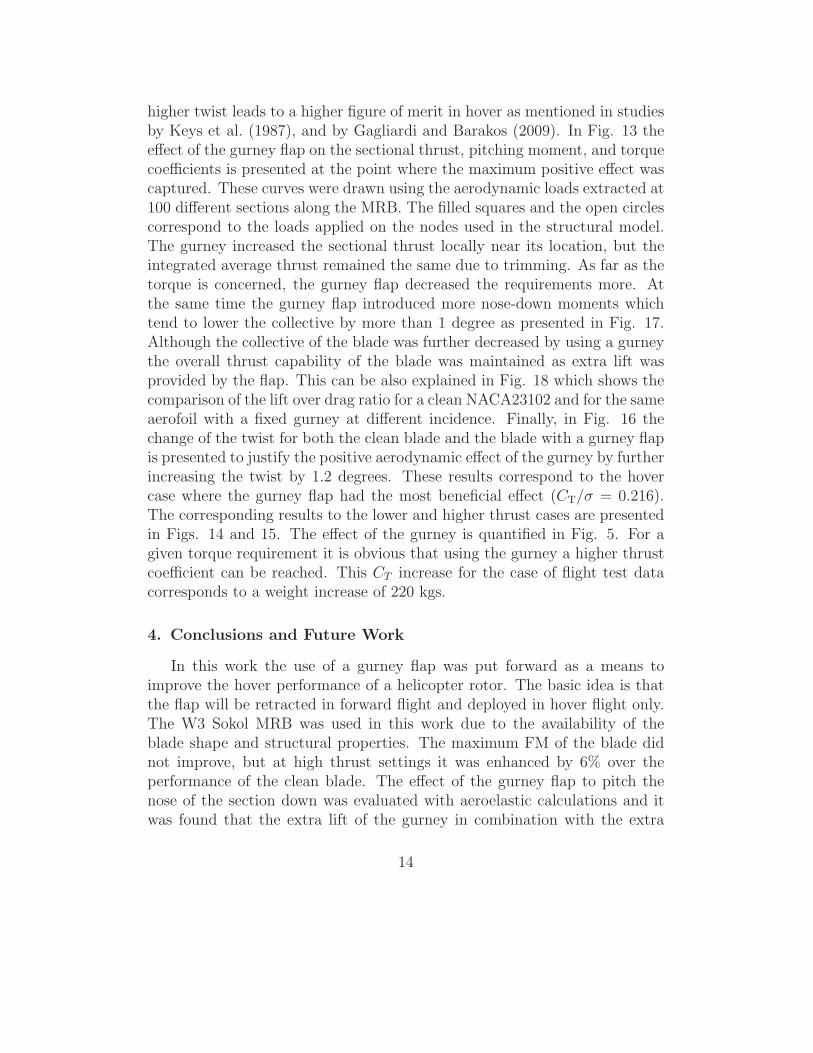
The mesh used for the hover calculations consists of 5.8 million nodes. Amesh convergence study suggested that this large number of cells was neededfor the blade-loads to converge. It is a combined C-type topology in they-plane with 402 nodes along the blade and O-type topology in the x-planewith 196 nodes around every section of the blade. In the normal direction ofthe blade 64 nodes have been used. The domain is split in 1360 blocks andit is presented in Fig. 2. For the 4-bladed W3-Sokol rotor, the periodicityboundary condition in space and time is applied in a sector of 2π/4 radians.At the farfield, the inflow, and the outflow surfaces the Froude condition forhover, presented by Wake and Baeder (1996), was applied. The farfield waslocated 52 chords away from the tip of the blade, while the inflow and outflowboundaries are located 30 and 60 chords away from the blade, respectively.
11

3.2. Rigid Blade Computations
3.2.1. Performance
Comparative performance calculations have been conducted at six differ-ent thrust targets for the rigid clean blade using the k − ω SST turbulencemodel. The collective and coning angles used at every case are presentedin Table1. The maximum FM was 0.74 and it was observed at mediumthrust settings (CT/σ = 0.185). At the same setting the torque coefficientwas CQ = 0.001. The hover performance for the clean blade as well as theblade with gurney flaps can be seen in Figs. 3 and 4, and an enlarged viewis presented in Fig. 5. Three vertical lines are also drawn in that figurecorresponding to estimated weight cases for a typical helicopter like the W3Sokol. In fact, the green line represents hover data provided by PZL Swidnikin order to validate the CFD methods. As demonstrated in Fig. 6a about200,000 iterations were needed for a well converged solution. If the trimmerwas also employed, it added an additional number of iterations since afterevery retrim the flow needs to adjust and further steps to converge.
3.2.2. Analysis of Rigid Blade Results
In Fig. 7a the surface pressure coefficient is presented and in Fig. 7bthe CP plots at three different sections for the clean blade can be seen. Ther/R = 0.56 station is where the gurney flap will be located, while in ther/R = 0.73 section the expected effect of the blade trim tab is observed.The trailing edge tab seems to have a similar effect, which can be seen fromthe pressure distribution at r/R = 0.89. In Fig. 8a the wake of the bladeis visualised using the vorticity magnitude of 0.1s−1, which shows that thevortex created at the tip of the blade interacts with the following blade at near0.89R, due to the wake contraction. After calculating the performance of theW3 rotor in hover, a gurney flap of 0.2R span was implemented at r/R=0.46of the blade. The height of the flap varied from 0.3%c up to 2%c and the flapwas assumed to be infinitely thin. Hover calculations were conducted for sixthrust settings and the HMB2 trimmer was used to force the blade to reachthe same thrust as the clean blade. It is pointed out that the gurney improvesthe performance of the rotor above medium thrust (CT/σ = 0.185). The mostbeneficial gurney size is 2% of the chord and the maximum benefit in figureof merit was +0.044 at CT = 0.0154 (CT/σ = 0.216) which correspondsto 6.3% increase compared to the clean case. These results can be seen inFig. 3. The gurney effect on the wake of the blade is well captured andit is presented in Fig. 8b using the isosurface of vorticity magnitude equal
12

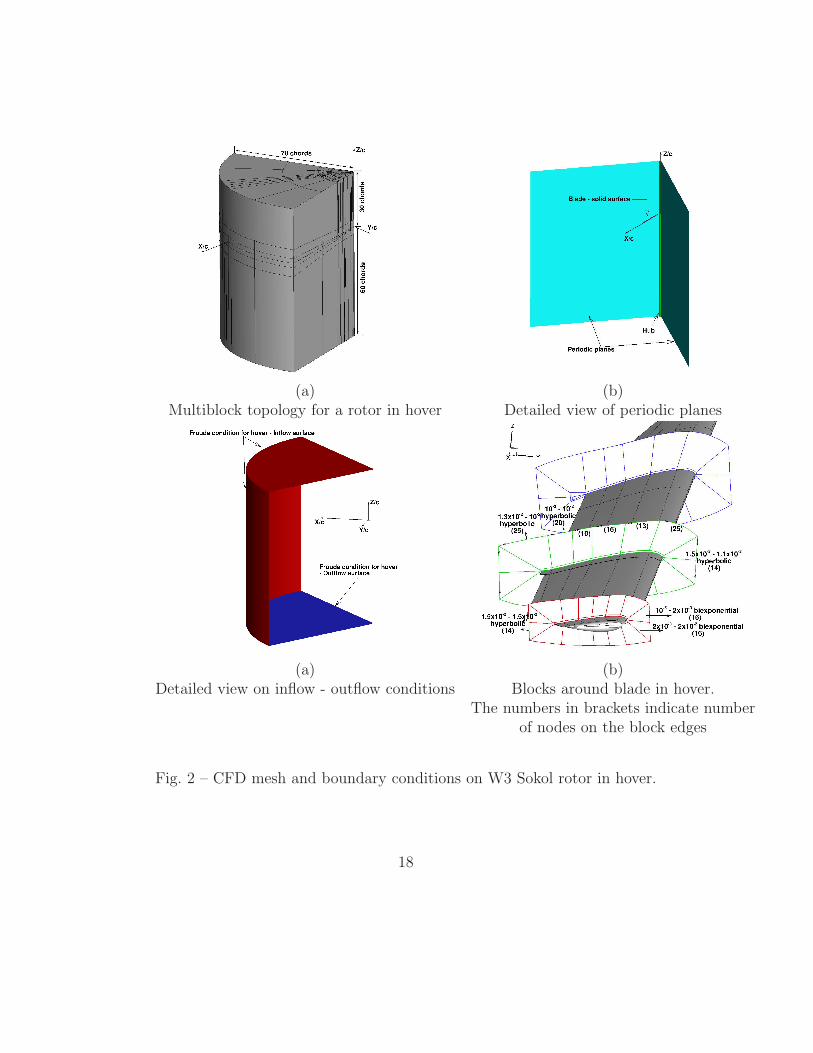
to 0.1s−1. For the clean case only the vortices created by the trim tab andthe tip of the blade are obvious, while on the blade with the fixed gurneythe vortex generated due to the flap is observed inboard. In Fig. 9(a-d) thepressure coefficient on the blade surface is presented for the blade with andwithout a gurney flap. The effect of the flap on the decrease of the pressureon the suction side and the increase of the pressure on the pressure side isclear, although this effect decays rapidly away from the tips of the flap. Afurther comparison is conducted between the sectional pressure coefficientsof both blades in Fig. 10. It shows that a gurney of 2%c alters the pressuredistribution at almost 80% of the sectional surface. At lower thrust wherethe collective of the blade is not very high the gurney extends more out ofthe boundary layer and creates additional drag leading to a decrease of theblade performance.
3.3. Aeroelastic Calculations
3.3.1. Application of the Aeroelastic Method and Trimming
Given the sectional properties of the blade, aeroelastic calculations wereconducted at the same thrust settings. In Fig. 11 the blade is modelled usingbeam elements in NASTRAN to calculate the deformed shape according tothe loads extracted from the flow solution. The structural properties ofthe blade are presented in Fig. 12 which suggests that this blade is softif compared to more modern designs. Especially, the beamwise and thetorsional stiffness are very low compared to the chordwise stiffness along theradius which allows the blade to flap and to twist more during flight. Theprocess of getting the final converged solution is summarised in Fig. 6b.Having obtained the converged solution for the rigid blade the aerodynamicloads along the blade are extracted and NASTRAN is used to obtain thenew deformed shape using a non-linear analysis (SOLxyz). The mesh isthen deformed according to that shape and the flow-field is updated untilconvergence. The trimmer is then employed to reach the required thrustcoefficient and the same process is repeated until the loads converge.
3.3.2. Analysis of Elastic Blade Results
The black dots in Figs. 3 and 4 correspond to the aeroelastic calculationsperformed for the W3 MRB and the performance of the blade is improved.The agreement between the estimated FM and this of tests is also better.The reason for the aerodynamic enhancement is partly due to the structuralproperties of the blade which allow some twist, and as a consequence, the
13
higher twist leads to a higher figure of merit in hover as mentioned in studiesby Keys et al. (1987), and by Gagliardi and Barakos (2009). In Fig. 13 theeffect of the gurney flap on the sectional thrust, pitching moment, and torquecoefficients is presented at the point where the maximum positive effect wascaptured. These curves were drawn using the aerodynamic loads extracted at100 different sections along the MRB. The filled squares and the open circlescorrespond to the loads applied on the nodes used in the structural model.The gurney increased the sectional thrust locally near its location, but theintegrated average thrust remained the same due to trimming. As far as thetorque is concerned, the gurney flap decreased the requirements more. Atthe same time the gurney flap introduced more nose-down moments whichtend to lower the collective by more than 1 degree as presented in Fig. 17.Although the collective of the blade was further decreased by using a gurneythe overall thrust capability of the blade was maintained as extra lift wasprovided by the flap. This can be also explained in Fig. 18 which shows thecomparison of the lift over drag ratio for a clean NACA23102 and for the sameaerofoil with a fixed gurney at different incidence. Finally, in Fig. 16 thechange of the twist for both the clean blade and the blade with a gurney flapis presented to justify the positive aerodynamic effect of the gurney by furtherincreasing the twist by 1.2 degrees. These results correspond to the hovercase where the gurney flap had the most beneficial effect (CT/σ = 0.216).The corresponding results to the lower and higher thrust cases are presentedin Figs. 14 and 15. The effect of the gurney is quantified in Fig. 5. For agiven torque requirement it is obvious that using the gurney a higher thrustcoefficient can be reached. This CT increase for the case of flight test datacorresponds to a weight increase of 220 kgs.
4. Conclusions and Future Work
In this work the use of a gurney flap was put forward as a means toimprove the hover performance of a helicopter rotor. The basic idea is thatthe flap will be retracted in forward flight and deployed in hover flight only.The W3 Sokol MRB was used in this work due to the availability of theblade shape and structural properties. The maximum FM of the blade didnot improve, but at high thrust settings it was enhanced by 6% over theperformance of the clean blade. The effect of the gurney flap to pitch thenose of the section down was evaluated with aeroelastic calculations and itwas found that the extra lift of the gurney in combination with the extra
14

blade twist resulted in an increased FM. For further performance improve-ment a gurney flap of bigger span could be considered. Among different sizesof gurney the one of 2% of the chord was the most effective. In the future,computations using a fuselage are considered and the location of the gurneywill be further optimised to maximise blade performance. The interaction ofthe wake generated by the rotor blade with the fuselage may affect the rotor-craft performance in such a way that a relocation or a change of the gurneysize may be essential. In addition, the effect of adding a mechanism for theflap actuation on the blade structural properties should be investigated.
Acknowledgements
The financial support via the IMESCON Marie Curie ITN project (grantagreement number: 264672), the release of the W3 Sokol main rotor bladegeometry by PZL Swidnik, and the use of the computing centre TASK ofGdansk, Poland, are gratefully acknowledged.
15

Case θ0 (deg) β0 (deg) CT
1 4.5 (3.6) 1.5 (0.6) 0.00452 7.0 (6.1) 2.5 (1.8) 0.00823 10.0 (9.1) 5.0 (4.1) 0.01324 11.5 (10.5) 6.0 (5.2) 0.01545 14.0 (12.9) 6.2 (5.5) 0.01896 16.0 (14.4) 10.0 (8.7) 0.0209
Table 1 – Control angles and target thrust coefficients for the clean W3-Sokolblade and the blade with fixed gurney flap of 2% of the chord (in brackets)in hover.
16

Fig. 1 – (I) Geometry of W3-Sokol MRB, (II) close view at the trim tab andthe trailing edge tab, (III) close view at the tip.
17
(a) (b)Multiblock topology for a rotor in hover Detailed view of periodic planes
(a) (b)Detailed view on inflow - outflow conditions Blocks around blade in hover.
The numbers in brackets indicate numberof nodes on the block edges
Fig. 2 – CFD mesh and boundary conditions on W3 Sokol rotor in hover.
18

Fig. 3 – Figure of merit versus thrust coefficient for the W3 Sokol MRB inhover (Mtip = 0.618, Retip = 3.74 · 106, σ = 0.0714).
19

Fig. 4 – Torque versus thrust coefficient for the W3 Sokol MRB in hover(Mtip = 0.618, Retip = 3.74 · 106, σ = 0.0714).
20

Fig. 5 – Estimated benefit in hover flight when a gurney flap is deployed(Mtip = 0.618, Retip = 3.74 · 106, σ = 0.0714).
21

(a)
(b)
Fig. 6 – (a) Convergence history for thrust coefficient, collective and coningangle during aeroelastic hover computations along with trimming process.(b) Flow chart for aeroelastic calculations in hover.
22

(a)
(b)
Fig. 7 – (a) Pressure coefficient along the W3 MRB and (b) pressure coef-ficient at different sections of the blade normalised using the local dynamichead, θ = 10o, β = 5o, CT = 0.0132, FM = 0.7432, CQ = 0.001.
23

(a)
(b)
Fig. 8 – Wake visualisation on W3 MRB (a) with out and (b) with gurneyflap in hover by using the isosurface of vorticity magnitude equal to 0.1 s−1,θ = 10o, β = 5o, CT = 0.0132, FM = 0.7432, CQ = 0.001.
24
(a) Clean blade
(b) Blade with gurney flap
Fig. 9 – Pressure distribution on upper and lower surface of W3 MRB withoutgurney (a) and with gurney (b). Clean blade: θ = 11.5o, β = 6o, CT/σ =0.216, FM = 0.6934, CQ = 0.00138. Blade with gurney flap: θ = 10.46o,β = 5.21o, CT/σ = 0.216, FM = 0.7374, CQ = 0.00129.
25

Fig. 10 – Pressure coefficient at r/R = 0.56 - Comparison between cleanblade and blade with gurney flap.
Fig. 11 – Structural model of the W3 Sokol blade used in NASTRAN.
26

Fig. 12 – Structural properties of the W3 Sokol blade used in NASTRAN.
(a) (b) (c)
Fig. 13 – (a) Sectional thrust coefficient, (b) pitching moment coefficient,and (c) torque coefficient of the W3 MRB with (dashed line) and withoutgurney flap (solid line). Clean blade: θ = 11.5o, β = 6o, CT /σ = 0.216,FM = 0.6934, CQ = 0.00138. Blade with gurney flap: θ = 10.46o, β = 5.21o,CT/σ = 0.216, FM = 0.7374, CQ = 0.00129.
27

(a) (b) (c)
Fig. 14 – (a) Sectional thrust coefficient (b) pitching moment coefficient,and (c) torque coefficient of the W3 MRB with (dashed line) and withoutgurney flap (solid line). Clean blade: θ = 10.0o, β = 5o, CT/σ = 0.1853,FM = 0.7432, CQ = 0.001. Blade with gurney flap: θ = 9.15o, β = 4.16o,CT/σ = 0.1853, FM = 0.7429, CQ = 0.001.
(a) (b) (c)
Fig. 15 – (a) Sectional thrust coefficient, (b) pitching moment coefficient, and(c) torque coefficient of the W3 MRB with (dashed line) and without gurneyflap (solid line). Clean blade: θ = 14o, β = 6.2o, CT/σ = 0.264, FM = 0.622,CQ = 0.0021. Blade with gurney flap: θ = 12.92o, β = 7.36o, CT/σ = 0.264,FM = 0.656, CQ = 0.0017.
28

Fig. 16 – Change of twist distribution for W3 MRB with and without gurneyflap in hover.
29

Fig. 17 – Collective angle after trimming versus CT/σ for different gurneysizes on the W3 MRB in hover.
30

Fig. 18 – Lift over drag comparison for a NACA23012 aerofoil with (dashedline) and without a gurney flap (solid line).
31

References
Albada, G. D. V., Leer, B. V., Roberts, W., 1982. A comparative study ofcomputational methods in cosmic gas dynamics. Astronomy and Astro-physics 108, pp. 76.
Bae, E. S., Gandhi, F., 2012. Upstream active Gurney flap for rotorcraftvibration reduction 2, pp. 1354–1362.
Baker, J. P., Standish, K. J., van Dam, C. P., March-April 2007. Two-dimensional wind tunnel and computational investigation of a microtabmodified airfoil. AAIA, Journal of Aircraft 44 (2), pp. 563–572.
Barakos, G., Steijl, R., Badcock, K., Brocklehurst, A., 2005. Development ofCFD capability for full helicopter engineering analysis. In: 31st EuropeanRotorcraft Forum, 13-15 September, Florence, Italy. pp. 91.1–91.15.
Cheng, R. P., Celi, R., 2005. Optimum two-per-revolution inputs for im-proved rotor performance. AIAA, Journal of Aircraft 42 (6), pp. 1409–1417.
Chow, R., Dam, C. P. V., Sept–Oct 2006. Unsteady computational inves-tigations of deploying load montrol microtabs. AAIA, Journal of Aircraft43 (5), pp. 1458–1469.
Dehaeze, F., Barakos, G. N., 2011. Aeroelastic CFD computations for rotorflows. In: 37th European Rotorcraft Forum, 13-15 September, Milan, Italy.pp. 143–162.
Dehaeze, F., Barakos, G. N., 2012a. Hovering rotor computations using anaeroelastic blade model. Aeronautical Journal 116 (1180), pp. 621–649.
Dehaeze, F., Barakos, G. N., 2012b. Mesh deformation method for rotorflows. AIAA, Journal of Aircraft 49 (1), pp. 82–92.
Gagliardi, A., Barakos, G. N., 2009. Analysis and design of a flap-equippedlow-twist rotor for hover. AIAA, Journal of Aircraft 46 (1), pp. 74–84.
Gai, S. L., Palfrey, R., 2003. Influence of trailing-edge flow control on airfoilperformance. AAIA, Journal of Aircraft 40 (2), pp. 332–337.
32

Jameson, A., 1991. Time dependent calculations using multigrid, with appli-cations to unsteady flows past airfoils and wings. In: 10th ComputationalFluid Dynamics Conference, Honolulu, HI. AIAA-91-1596.
Jeffrey, D., Zghang, X., March-April 2000. Aerodynamics of Gurney flapson a single-element high-lift wing. AIAA, Journal of Aircraft 37 (2), pp.295–301.
Jeffrey, D., Zhang, X., Hurst, D. W., 2000. Aerodynamics of Gurney flaps ona single-element high-lift wing. AAIA, Journal of Aircraft 37 (2), 295–301.
Keys, C., Tarzanin, F., McHugh, F., 1987. Effect of twist on helicopter per-formance and vibratory loads. In: 13th European Rotorcraft Forum, Arles,France.
Kinzel, M. P., Maughmer, M. D., Duque, E. P. N., July 2010. Numericalinvestigation on the aerodynamics of oscillating airfoils with deployableGurney flaps. AIAA Journal 48 (7), pp. 1457–1469.
Lee, T., Su, Y. Y., 2011. Lift enhancement and flow structure of airfoil withjoint trailing-edge flap and Gurney flap. Experiments in Fluids 50, pp.1671–1684.
Liebeck, R. H., Sept 1978. Design of subsonic airfoils for high lift. AIAA,Journal of Aircraft 15 (9), pp. 547–561.
Liu, L., Padthe, A. K., Friedmann, P. P., July 2011. Computational studyof microflaps with application to vibration reduction in helicopter rotors.AIAA Journal 49 (7), pp. 1450–1465.
Lorber, P., Hein, B., Wong, J., Wake, B., 2012. Rotor aeromechanics resultsfrom the sikorsky active flap demonstration rotor. In: 68th Annual AHSForum, AHS International. Vol. 1. pp. 553–568.
Maughmer, M. D., Bramesfeld, G., 2008. Experimental investigation of gur-ney flaps. AAIA, Journal of Aircraft 45 (6), pp. 2062–2067.
Milgram, J., Chopra, I., Straub, F., 1998. Rotors with trailing edge flaps:Analysis and comparison with experimental data. Journal of the AmericanHelicopter Society 43 (4), pp. 319–332.
33

Min, B., Sankar, L. N., Rajmohan, N., Prasad, J. V. R., 2009. Computationalinvestigation of gurney flap effects on rotors in forward flight. AIAA, Jour-nal of Aircraft 46 (6), pp. 1957–1964.
MSC Software Corporation, 2005. MSC.Nastran 2005 release guide.
Osher, S., Chakravarthy, S., 1983. Upwind schemes and boundary condi-tions with applications to euler equationsin general geometries. Journal ofComputational Physics (50), pp. 447–481.
Padthe, A. K., Liu, L., Friedmann, P. P., 2011. Numerical evaluation of mi-croflaps for on blade control of noise and vibration. In: Collection of Tech-nical Papers - AIAA/ASME/ASCE/AHS/ASC Structures, 52nd Struc-tural Dynamics and Materials Conference, 4-7 April, Denver, Colorado.AIAA-1873.
Steijl, R., Barakos, G., 2008a. A computational study of the advancing sidelift phase problem. AIAA, Journal of Aircraft 45 (1), 246–257.
Steijl, R., Barakos, G., 2008b. Sliding mesh algorithm for CFD analysis of he-licopter rotor-fuselage aerodynamics. International Journal for NumericalMethods in Fluids 58, 527–549.
Steijl, R., Barakos, G., Badcock, K., 2006. A framework for CFD analysisof helicopter rotors in hover and forward flight. International Journal forNumerical Methods in Fluids 51 (8), 819–847.
Steijl, R., Woodgate, M., Barakos, G. N., 2010. CFD Method for EfficientAnalysis of Flapped Rotors. AHS Specialists’ meeting on Aeromechanics,AHS International, 20–22 January, California, USA, pp. 505–517.
Sterenborg, J. J. H. M., Lindeboom, R. C. J., Ferreira, C. J. S., van Zuijlen,A. H., Bijl, H., Feb 2014. Assessment of PIV based unsteady load deter-mination of an airfoil with actuated flap. Journal of Fluids and Structures45, pp. 79–95.
Tang, D., Dowell, E. H., July-August 2007. Aerodynamic loading for anairfoil with an oscillating Gurney flap. AAIA, Journal of Aircraft 44 (4),pp. 1245–1257.
34
Troolin, D. R., Longmire, E. K., Lai, W. T., 2006. Time resolved PIV analysisof flow over a NACA 0015 airfoil with Gurney flap. Experiments in Fluids41, pp. 241–254.
Viswamurthy, S. R., Ganguli, R., 2004. An optimization approach to vibra-tion reduction in helicopter rotors with multiple active trailing edge flaps.Aerospace Science and Technology 8 (3), pp. 185–194.
Wake, B. E., Baeder, J. D., 1996. Evaluation of a navier-stokes analysismethod for hover performance prediction. Journal of the American Heli-copter Society 41 (1), pp. 7–17.
Wang, J. J., Li, Y. C., Choi, K. S., 2008. Gurney flap - lift enhancement,mechanisms and applications. Progress in Aerospace Sciences 44, pp. 22–47.
Woodgate, M., Barakos, G. N., 2012. Rotor computations with active gur-ney flaps. 38th European Rotorcraft Forum, 4–7 September, Amsterdam,Netherlands (54).
Yee, K., Joo, W., Lee, D. H., May–June 2007. Aerodynamic performanceanalysis of a Gurney flap for rotorcraft applications. AIAA, Journal ofAircraft 44 (3), pp. 1003–1014.
Yeo, H., 2008. Assessment of active controls for rotor performance enhance-ment. Journal of the American Helicopter Society 53 (2), pp. 152–163.
35