elliptical turning - aawcontentsource.org · you fear a bearer will slip during attach - ment, try...
TRANSCRIPT

28 American Woodturner December 2015
David Springett
JOURNAL ARCHIVE CONNECTIONFor more on elliptical turning, see “Oval Traditions” (AW vol 19, no 2, page 24), a 2004 article in which Alan Lacer describes oval turning at the historic Old Schwamb Mill. AAW members can access all past journal articles online at woodturner.org.
American Woodturner Summer 2004
24
T U R N I N G B A C K T H E C L O C K
because it requires considerablehandwork to blend the differentturning operations. Another option is incorporating
a chucking system that performsthis operation during eachrevolution of the lathe. Such
chucks have been mentioned inliterature even in the early 1700s.An amazing shop located justoutside of Boston still employsthat method.
We are soobsessed withturning round objectswith our lathes that weforget there are long traditionsof doing shapes other than circles.For instance, there is the processof off-center turning between thecenters to produce such objectsas simulated cabriole legs oras you might see in Mark Sfirri’sturnings.
But with face work, therehas been a parallel tradition ofvarying the central axis toproduce ovals or ellipses.Turners could accomplish this
by remounting a piece ondifferent axes, although somefind this method unrewarding
Oval
The Old Schwamb Millin Arlington, in continuousoperation since 1864, hasspecialized in oval frames for 140
years. Although the mill doesn’tproduce the volume it once didduring its heyday of the late 19thand early 20th centuries, it stillturns out the same high-qualityoval picture and mirror framesthat brought it considerablenotoriety decades ago.
TraditionsBy Alan LacerA visit to the oldestcontinuously operatingmill in North America
ELLIPTICAL TURNING on a
SHOPMADE CHUCK
The shopmade elliptical chuck described here allows you to turn
elliptical frames and lidded boxes. It can be adjusted for a range of
different ellipses.
E lliptical, or oval, turning is fas-cinating and mysterious, yet entirely possible for woodturn-
ers using a shopmade chuck on the headstock of a regular wood lathe. The chuck is a fairly complex piece of apparatus (Figure 1), but you can make it by following the sequences accompanying this article. You can see the chuck in action in my short video, where you will also hear it vibrating and clattering as it whirls (see end of this article for links to the video).
Because of the complex motion of the workpiece, elliptical turning is quite unlike regular turning.
There’s a lot of noise and vibration. Surprisingly, the cut is constant once you establish the ellipse, not intermittent, provided you take light cuts and hold the tool tight on the rest. The profile is difficult to view while the lathe is running and not all tools will work, since tracing an ellipse involves a long sweeping curve quickly followed by a tighter curve. This tighter curve can trap deep parting tools and interfere with a gouge’s bevel, but small scrapers and gouges work well enough, provided the cut stays right at the lathe’s center height.
28_Elliptical.indd 28 11/11/15 9:40 AM
Copyright 2015, 2016, American Association of Woodturners. All rights reserved.

29woodturner.org
F E A T U R E
Because of the elliptical motion of this shopmade chuck, there is always a risk that something could come apart. That’s why, except for fasteners and the threaded rod, the chuck is made entirely of wood, with each piece carefully chosen for its purpose. While you could experiment with making the cam of plywood and Morse-tapered shank of nylon or Delrin®, it would not be safe to introduce metal parts.
Headstock box: Dimension to fit your lathe; make of hardwood plywood joined with glued-and-screwed battens.
Circular cam: Dense hardwood, 3" (8cm) diameter by ¾" (19mm) thick; choose species to minimize wood movement. Cam shown was oriented end-on, long grain parallel to the lathe axis.
Camplate: ¼"- (6mm-) thick hardwood plywood, 9½" × 5" (24cm × 13cm).
Slide with Morse-tapered shank: Dense hardwood (I used pau amarello), 6¼" (16cm) long by 3" (7.6cm) by 2" (5cm); make as one piece or join from two pieces.
Runners: Glue up four pieces of oak, two 6¼" long by 1¼" (32mm) wide by 11 ⁄16" (17mm) thick; two 6¼" long by 1¼" wide by ¼" thick.
Bearers: Two pieces of oak, 3⅜" (9cm) long by 1⅛" (29mm) wide by ½" (13mm) thick.
Faceplate: ¼"-thick hardwood plywood, 7⅝" × 7" (19cm × 18cm).
Hardware: Four ¼" pan-head bolts with cross slot for screw-driver, 2" long, with nuts; one 5 ⁄16" (8mm) threaded rod, 3' (1m) length cut to fit your lathe, with two square nuts; various screws, including several 1"- (25mm-) long #6 flathead steel screws to attach the bearers.
Elliptical chuck parts
Required Materials
Figure 1.
Headstock box
Camplate
Runners
Morse-tapered shank
Circular camBearers
Faceplate
Slide
Threaded drawbar
Square nut
28_Elliptical.indd 29 11/11/15 9:41 AM
Copyright 2015, 2016, American Association of Woodturners. All rights reserved.

30 American Woodturner December 2015
1
2
As you’ll see in the elliptical frame project on page 34, it is crucial to saw the blank close to finished shape and to mount it securely on the oscillating faceplate—I use newspaper glue joints and hot-melt glue on pre-heated mating surfaces so there is time to position carefully. You will find yourself having to remove a straight line at the center of the work, not the usual circular nub (Photo 1), and the line can be difficult to remove. The solution is to keep the edge of the tool cutting at the lathe’s center height, which you can locate by shining a level laser line onto the whirling workpiece (Photo 2).
The laser solution was devised by the late Prof. Johannes Volmer. If you become seriously interested in elliptical turning, then you must visit his website, volmer---Ovaldrehen.de. He made the most comprehensive study of oval turning and was the designer of the Steinert® picOval lathe, which is capable of turning ellipses at high speed.
How the chuck worksThe chucking apparatus consists of a rigid wooden headstock box bearing an adjustable camplate and an offset circular cam. The lathe rotates a slide mechanism that drives a pair of runners and bearers riding the offset cam while carrying a faceplate and, ultimately, the workpiece (Figure 1). The combined rotation of the slide with the back-and-forth action of the runners moves the faceplate on an elliptical path. The farther off center you locate the circular cam, the more pronounced the elliptical shape.
This is an all-wood chuck that effi-ciently rubs wood on wood. There can be considerable vibration while turning, especially at low speeds, against some risk of burning due to friction at higher speeds. Do not go faster than 500 rpm, and work in short bursts to keep everything cool, including yourself: this work requires intense concentration. And be sure to keep an eye on all screws and fixings while you work; they can easily vibrate loose.
Making the chuckDimension the headstock box to fit your lathe, making sure its front plate is truly vertical and square to the ways. Mine was made from plywood joined with glue, screws, and solid-wood battens. The box holds a wood camplate firmly in place, with the lathe spindle protrud-ing through its center hole, so it must be rigidly clamped to the lathe ways.
The camplate carries a circular cam at center height bolted in place through slotted holes, permitting sideways adjustment to change the major axis of the ellipse. The hardwood cam has an elongated center hole, so it too can be adjusted sideways; the back corner of the camplate might need to be cut away to avoid interfering with the lathe motor. Use the slots in the camplate to mark holes for the fixing bolts on the front of the headstock box.
The slide mechanism consists of a wooden shank Morse-tapered to fit the headstock spindle, driving a rectangular
wooden slide with beveled edges. The slide mechanism is fixed directly to the head-stock by a threaded drawbar through the lathe’s hollow spindle, so it rotates like a propeller. The photo and figure sequence, Slide with Morse-tapered shank, shows the slide mechanism sawn, bored, and turned from one piece of dense hardwood, with the tight drawbar overcoming any short-grain weakness. You could instead make it of two pieces, a Morse-tapered shank tenoned and glued into the slide piece. You would be making the shank of long-grain wood, but you might have to juggle dimensions to set the nut down flush.
A pair of runners mounted on a pair of bearers fits over the slide and can move back and forth along the slide. The bearers
The edge of the lathe tool must cut at the lathe’s center height. Deviation above or below center will create a new pathway and a confusing profile.
Guide the cut by shining a center-height laser line onto the faceplate. The cutting angle may not always be perfect but its position will be.
Cut at center height
To lock the front of the headstock box in position, make a simple toggle that can be tightened under the lathe bed.
The front of the headstock box must be vertical and square to the lathe ways. Mark a horizontal line across the face of the box at center height and note how far the spindle projects, as this distance limits the thickness of the cam and bearers.
Headstock box
28_Elliptical.indd 30 11/11/15 11:30 AM
Copyright 2015, 2016, American Association of Woodturners. All rights reserved.

31woodturner.org
F E A T U R E
9½"
3"
saw slot
1"1⅝"
¾" ¾"1⅝"
1"
3" dia. cam
optional cut-out
1" dia. drill5"
¼"
2" 3⅝"
are screwed to the runners at right angles, parallel to each other and spaced exactly the cam-diameter apart. This keeps them in close contact with the cam as the chuck rotates, creating the elliptical motion. I made these parts from a less-dense hardwood, oak, because they are easier to replace than the slide and are the parts that wear out first.
Final fittingWhen you fit the bearers to the cam, check with a square that all parts stay in line. If you fear a bearer will slip during attach-ment, try running a weld of hot-melt glue along the edge away from the shank. The bearers should make a good firm fit against the circular cam and run easily, as should the runners on the slide. Lubricate the wood with candle wax or spray-on furniture polish. Depending on how far your lathe spindle projects from the head-stock box (⅞", or 22mm, on my setup), you might need to adjust the cam thickness, bearer thickness, or slide length so every-thing moves without interference.
To fit the drawbar that connects the chuck to the headstock spindle, turn a simple handwheel for the outboard side, center-bore it 5 ⁄16" (8mm) and epoxy a nut into it. Lock down the camplate and push the bearers onto it, guiding the wooden Morse taper into the headstock spindle. Feed the threaded rod through the headstock spindle and screw it into the slide nut. Now you can mark and cut the rod to length on the outboard side, then attach and tighten the handwheel to lock everything into place. Adjust the fit as needed before you epoxy the threaded rod into the slide.
Make the faceplate from ¼"- (6mm-) thick hardwood plywood, carefully rounding its corners. Screw the faceplate to the runners, and the elliptical chuck is ready to run. Rotate the lathe by hand to see the elliptical motion. It should be a tight, squeaky movement. To test it, run the lathe at 500 rpm and mark your first ellipse with a pencil held firmly on the centerline.
Make a camplate from ¼" plywood marked out according to the drawing. Drill and cut slots for mounting bolts.
Mount and turn the cam blank on a softwood faceplate using a newspaper glue joint that you can split when done. Make sure the edge is 90° to the face and mark clear centerlines. (Note: A primer on making good newspaper glue joints can be found in one of David Springett’s prior AW articles, in vol 30, no 1, page 28.)
Glue the circular cam on the centerline of the camplate; note that it is offset toward one end.
Mark and drill the cam and plate using a 1" (25mm) saw-tooth bit. Use a coping saw to join the two holes, and rasp to clean up the slot.
Add plywood squares to locate and glue nuts on the back side of the headstock box front. These nuts will accept the camplate's mounting bolts.
Cam and camplate
28_Elliptical.indd 31 11/11/15 9:41 AM
Copyright 2015, 2016, American Association of Woodturners. All rights reserved.

32 American Woodturner December 2015
Morse taper
Boss
Recessed nut
Recessed nut
Threaded bar
HandwheelSlide
2"
2"
45°2½"
½"
½"
2½"
½"
3"
1¼"
6¼"
6¼"
5⁄16" hole
5⁄16" dia. boss9⁄16" long
Grain
Square hole for nut
Morse taper to fit lathe
(Upper left) For optimum strength, the slide is best made from a single block of wood.
(Upper right) The finished slide.
(Lower right) Slide and drawbar assembly. The drawbar extends through the hollow lathe spindle and holds the slide firmly in place.
Slide and drawbar
SLIDE WITH MORSE-TAPERED SHANK
(Left to right) Saw the waste away from the slide blank and bore a 5⁄16" (8mm) vertical hole through its marked center.
Use a Morse taper accessory such as a live center to take measurements for turning the shank of your slide. (Note: If you use the tailstock to take these measurements, be sure the tailstock and headstock have the same Morse taper size. If not, take the measurements using the headstock.) Insert the live center, mark where it exits, and measure this diameter: about 11⁄16" (17mm) for a No. 2 Morse taper. Take the diameter at a point 1⅞" (47mm) from the exit mark: about ⅝" (16mm).
Use the hole to locate the blank on a 5⁄16" dowel centered in a wooden faceplate. Secure it with two screws plus a weld of hot-melt glue.
Turn the central boss fully round and down to about 15⁄16" (24mm) diameter. Clean up to the flat face of the slide.
Prepare and mount stock
Turn the Morse taper Shape the slide
Cut a shoulder 9⁄16" (14mm) from the flat face, and turn the shank to match the measured taper. Turn with care, testing the fit in the tailstock.
Mark the 45° bevels on the top of the slide and plane the slope to the layout lines.
Chisel a recess for the 5⁄16" square nut and set it flush to the surface of the slide.
28_Elliptical.indd 32 11/11/15 9:41 AM
Copyright 2015, 2016, American Association of Woodturners. All rights reserved.

33woodturner.org
F E A T U R E
½"½"
1½"
1½"
1¼"
¼"
½"
½"¾"
7" 7⅝"
Rounded corners
2¼"
2¼"
6¼"
3⁄16"
11⁄16"
1⅛"
2⅝" approx
Counter sunk to accept No. 6 screw
1⅛"
3⅜"
Runners
Faceplate
Affix bearers to runners
RUNNERS, BEARERS, AND FACEPLATE
The slide mechanism moves between runners mounted on bearers that are set the cam diameter apart. The work-holding faceplate, at right, gets screwed to the runners and moves with them.
One bearer has joined holes to form slots for adjustment. Choose #6 screws long enough to penetrate solid wood, but make sure they do not foul the sliding grooves.
The faceplate has four #6 countersunk screw holes positioned to penetrate the runners while avoiding the sliding grooves.
To change faceplates, clamp the runners against the slide to hold them in position while you loosen screws.
Mark a centerline squarely across the two runners, flanked by lines the cam diameter apart. Clamp or glue-tack one bearer on the line, then screw the other bearer against the cam and adjust for a firm fit.
Create two identical runners to fit the slide by assembling each from two pieces of hardwood. Plane the 45° bevels before assembly. Glue and clamp the two parts, and be sure to remove any squeezed-out glue.
Bearers
28_Elliptical.indd 33 11/11/15 9:41 AM
Copyright 2015, 2016, American Association of Woodturners. All rights reserved.
34 American Woodturner December 2015
In elliptical work, you must always turn with the tool edge precisely at center height, the Point of
Tranquility, where the cut is still and the turning is easy. Misaligned cuts result from the tool cutting above or below the centerline; raising or low-ering the gouge to “improve” the cut will only cause trouble.
Turning elliptical frames always poses the additional problem of how to hold the workpiece. My solution, the best I’ve found so far, relies on newspaper glue joints in a careful sequence, as follows:
1) Newspaper-glue the blank face down on the elliptical chuck’s faceplate. Turn the rebate in the back that holds glass, picture, and backing, leaving enough rim (at least ⅜", or 10mm) for the wall-hanging fixings. Separate the joint to remove the workpiece.
2) Newspaper-glue an oversized blank onto the faceplate and turn an elliptical plug to fit inside the elliptical rebate. Newspaper-glue the workpiece onto it.
3) Turn the outer edge of the workpiece down into the supporting plug. Turn through to remove the center waste, then shape the inside of the frame. Sand and polish, then separate the newspaper glue joint to release the finished frame.
This project, scaled to the chuck just described, produces an oval frame about 5" (13cm) high and 4" (10cm) wide, with variations in size depending on how far you offset the circular cam. Make the frame from a piece of hardwood 6" (15cm) by 4½" (11cm), 1" (25mm) thick; the photos show maple. You’ll also need tracing paper, pencil and felt pen, masking tape, white glue, newspaper, hot-melt glue, and two #6 × 1" wood screws.
Bumpy cuts can be caused by loose runners in the chuck; inconsistent cuts usually result from worn parts or loose fixings. Before each work session, give the chuck a complete checkup. Replace any worn parts and tighten where needed.
For straight-in cuts, a square-end cutting tool works best, ideally sup-ported on a flat, shelf-like toolrest. For shaping cuts, use a typical tool-rest and small gouge.
ELLIPTICAL FRAME
Turning an
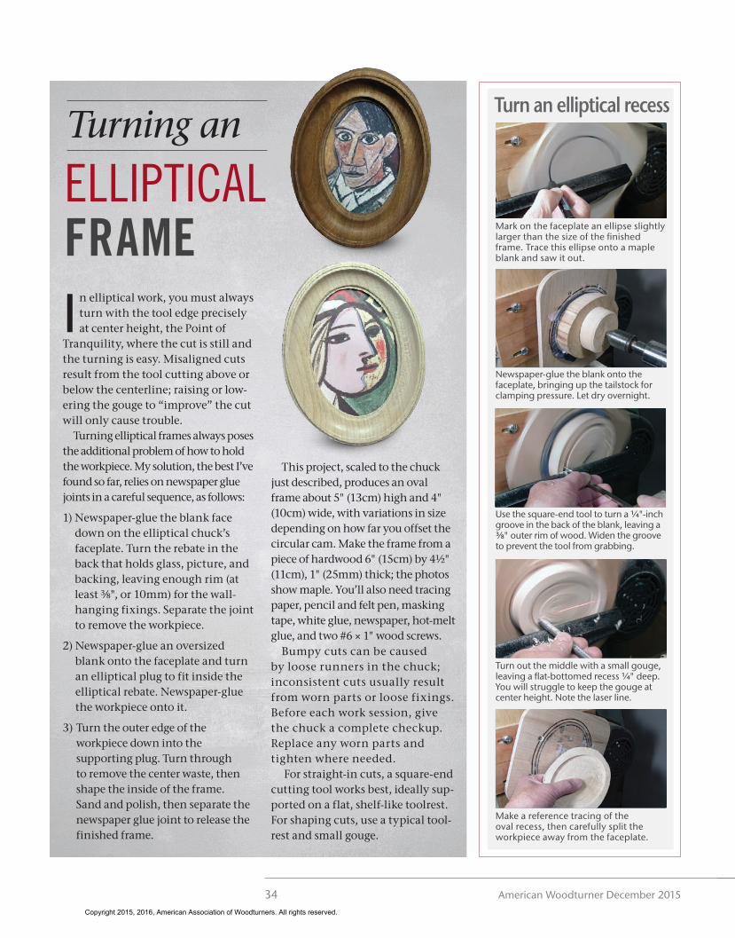
Make a reference tracing of the oval recess, then carefully split the workpiece away from the faceplate.
Turn an elliptical recess
Mark on the faceplate an ellipse slightly larger than the size of the finished frame. Trace this ellipse onto a maple blank and saw it out.
Newspaper-glue the blank onto the faceplate, bringing up the tailstock for clamping pressure. Let dry overnight.
Use the square-end tool to turn a ¼"-inch groove in the back of the blank, leaving a ⅜" outer rim of wood. Widen the groove to prevent the tool from grabbing.
Turn out the middle with a small gouge, leaving a flat-bottomed recess ¼" deep. You will struggle to keep the gouge at center height. Note the laser line.
28_Elliptical.indd 34 11/11/15 9:42 AM
Copyright 2015, 2016, American Association of Woodturners. All rights reserved.

35woodturner.org
F E A T U R E
Turn an elliptical recessSaw an oversized ellipse of 1"-thick wood, cut notches for access to screws, then newspaper-glue the blank to the faceplate and clamp with the tailstock.
Turn the outer edge of the oval frame and extend the turning into the supporting wood. Keep the cutting edge on the lasered centerline.
Turn the inside profile of the frame with a small gouge, always cutting on the centerline.
Sand and polish the inside profile and, when satisfied, peel away the glue weld.
The newspaper glue joint now can be split to release the finished frame.
Turn the frame down to ¾" (19mm) thick, avoiding the two screws. Sand and polish the edge, then, for added support, glue-weld the joint between chuck and workpiece with hot-melt glue.
Use the recess tracing as a guide to mark the smaller frame opening, then with the square-end tool, turn through to the supporting plug. Unscrew the center waste and remove it.
Draw an ellipse to match the turned recess and use the small square-end tool to turn a 1⁄16" (2mm) trial plug. Confirm the fit before cutting the plug to ¼" height.
Drill and countersink two screw holes in the middle of the recess. Newspaper-glue the workpiece to the plug and tighten the screws.
Remount on a plug chuck
Turn the picture frame
David Springett is a British woodturner known for his inventive creations. He is the author of Woodturning Wizardry, Woodturning Full Circle, Woodturning Magic, and, with Nick Agar, Woodturning Evolution.
All illustrations by Robin Springett.
You read the article—now see the video!This article has an accompanying online video in which David Springett further explains and demonstrates the use of this shopmade elliptical chuck. To view the video, visit tiny.cc/TurnElliptical (case sensitive) or scan the QR code with your mobile device.
28_Elliptical.indd 35 11/11/15 9:42 AM
Copyright 2015, 2016, American Association of Woodturners. All rights reserved.