ella+ integrated amplifier - diy hifi supply – take ...manual 3.7.pdf · le club hifi : ella+...
TRANSCRIPT

Le Club Hifi : Ella+ Integrated Amplifier DIY HiFi Supplywww.diyhifisupply.com

Table of Contents................................................................................................................................................................................................................................................ 2Chapter 1-Introduction............................................................................................................................................................................................................3Chapter 2 – Specification and Parts........................................................................................................................................................................................5Chapter 3 - Installation Notes................................................................................................................................................................................................. 7Chapter 4 – the Hardware....................................................................................................................................................................................................... 8Chapter 5 – Input Connections............................................................................................................................................................................................. 10Chapter 6 – Power Transformer Connections...................................................................................................................................................................... 13Chapter 7 – Output transformer Connections.......................................................................................................................................................................15Chapter 8 – DC power supply and tube connections............................................................................................................................................................17Chapter 9 – Operational notes.............................................................................................................................................................................................. 25Chapter 10 - Final Words and Tweaks................................................................................................................................................................................. 26
Chapter 1-IntroductionDue to reasonable input sensitivity and a volume pot, the Ella can be connected directly to a line level source. If connected using the Django TVC through the 'P' inputs (which bypass the remote function and direct connect to the input stage), the sonic result will be even better. The circuit is comprised of three stages: 6922 as the first SRPP stage, followed by 6N8P (6SN7) driver stage with EL34/KT88/6550/KT100 as the final power stage in classic push-pull class AB configuration. This is a classic circuit and the sonic performance is very high due to the design of the output transformer, tube circuit optimisation and years of experience in development. In addition, the power supply does not sag during transients as it is completely dual mono fed from a common low source impedance power transformer. It uses fixed bias design with external individual bias adjustment for each EL34. The EL34 is rugged and sweet sounding. Due to the robust power transformer and output transformers, 6550/KT88 can also be used with a resulting increase in output power to about 50+ watts, however many feel the EL34 can not be bettered for sound quality.
Low NFB with bias regulation ensures optimal tube regulation and sound. 40-50 watts (remember, these are tube watts) means you don't need new high-efficiency speakers and that your current speakers will be driven to shake and quake levels. Dual triode input stage and soft start are just some of the user-friendly features. The Ella comes with a remote, instruction manual, and all tubes (if ordered). The chassis is preassembled with aluminum front panel, 2 PCBs with premounted components; power transformer M6 laminations in the output transformers. The OPT are the soul of any tube amp and the latest generation is CNC wound for perfect lay, low capacitance and very wide power bandwidth. The large chassis and generous size dissipates heat evenly; it is normal for the chassis and power transformer cover to feel hot due to the efficiency of heat transfer from critical parts. The unit looks good as well. The combination of SRPP, and very low NFB adds up to truly high end sound. Dynamics are impressive, as is openness and soundstaging. Its performance belies its price many times over.The kit builder needs to have a basic knowledge of soldering. Refer to the many diagrams to avoid wiring mistakes. Parts quality are excellent. The stepped attenuator is standard and is especially impressive in the way it lets the music flow.

RequirementsThe kit builder needs to have basic soldering skills and be able to read and understand the wiring diagrams presented. Refer to the text and diagrams at each step throughout the manual and ensure you double check all wiring at each stage. It is also advantageous to refer to the circuit diagrams at the back of the manual throughout the build.
WarrantyThe kit cannot be returned for a refund. Defective parts will be replaced provided they are returned within 30 days of purchase and are confirmed defective and not misused. No further Warranty is expressed or implied. This is to protect you the buyer to be assured of receiving a brand new kit and not one that has been returned by someone else which may have been misused.
Disclaimer
DIY HiFi Supplywww.diyhifisupply.com
This manual is the property of DIY Hifi supply Ltd and may not be reproduced or distributed by any means in whole or in part.
Right to use the manual for the construction of the Ella kit is granted to the purchaser of the kit.
WARNING: The high voltages present in this kit can kill and the high operating temperatures can burn. Observe all precautions and never connect the kit to an electrical supply until it has been fully assembled, checked and ready for testing. You assume total responsibility and liability for the use and operation of this kit both for yourself and people around you. Confirm that large capacitors are discharged before working on the amplifier

Chapter 2 – Specification and Parts
Specifications• Power output: 40 Watts x 2, RMS @1Khz with EL34, more with other tube sets• Frequency response: 6Hz to 60KHz (-3dB@10W)• Total harmonic distortion: < 1% (40W@1Khz)
Input sensitivity and impedance: 550mV, 50K ohm• INPUT IMPEDANCE: 100k ohms• OUTPUT IMPEDANCE: 4 , 8 and 16 ohm• Signal to noise: 90dB• POWER CONSUMPTION: 110/220V AC, +- 10%, 90W 85W• CONTROL FUNCTIONS: Volume/select/mute , Front panel: Power On/Off, • INPUT INTERFACES: 4 groups (RCA) 1,2,3 and 'P' for bypass use as a power amplifier• OUTPUT INTERFACES: 4 Groups 4-way binding Post• Vacuum tubes: 6922 x 2 or equivalent, 6N8P x 2 or equivalent, EL34 x 4 or 4 x KT88, 6550, KT100
• Dimension (mm) and weight: 340(L) x 410(W) x 230(H), 25kg net
UnpackingRemove the bottom cover from the chassis, take out the loose kit parts and check against the list. Some minor variations in value are perfectly acceptable (ie 47k instead of 43k etc)

Standard Level 1 Parts List•
•
Level 2: 6 x Obliggato CU case film cap: 2 x 0.47 + 4 x 0.22; 8 pcs teflon tube sockets; 10M 1mm pure silver wire and teflon tubing; Kiwame resistors: 2w – 2 x 1m, 2 x 24k, 2 x 24r. 4 x 470r, 6 x 1k, 2 x 15k, 2 x 43k, 2 x 51k, 4 x 220r. 4 x 10r
Level 3: 6 x AN CU PIO: 2 x 0.47 + 4 x 0.12; 8 pcs teflon tube sockets; 10M 1mm pure silver wire and teflon tubing; AN tantalum resistors: 0.5w – 2 x 1m, 2 x 24k, 2 x 24r. 1.0W – 4 x 470r, 6 x 1k, 2 x 15k, 2 x 43k, 2 x 51k, 4 x 220r. 2W – 4 x 10r
8 Speaker binding posts (6 red, 2 black)
Machine screws, nuts & washers Plastic cable tieschassis, PS transformer, output transformerRemote control
1 power switch4 22K bias pots 1 IEC power socket with fuse2 PCB for power supply 1 100K stepped attenuator and supporting logic 1 Power LED & Resistor
6 Tube Sockets (8 pin)2 Tube Sockets (9 pin)
2 Choke2 0.47uF / 630V
4 10R/2W 4 0.1uF / 630V4 220R/1W6 1K6 100K 2 43K 2 100pF minature (variation allowed)2 51K Options:2 15K 2 69222 22K 2 6N8P4 470R 4 EL-34 2 1M4 50r

Chapter 3 - Installation Notes
Recommended SolderIt is recommended that solder with flux, designed for electronics is used. This usually has up to 2% of Silver that prevents the joint from becoming brittle over time. It provides a much stronger solder joint but can be difficult to work with due to its lower ‘wetting’ properties, it does not flow as easily. Some electronics solder has a small amount of copper instead which has very good ‘wetting’ properties. Whichever solder you use, make sure that you avoid poor solder technique.
Solder TechniqueSolder means to apply the iron tip to the point that needs to be soldered to heat it and at the same time apply the solder. The iron and solder come together at the same time when soldering any joint or tinning a wire and the solder should start to flow evenly around the joint. Allow the solder to cool naturally and do not blow on it. The finished joint should appear shiny and not dull. Many problems are due to poor solder technique. Clean the iron tip regularly on a wet sponge between each soldering step.
Connections Always wrap the wire around the connection point to make a good mechanical connection.
Connect means to dress a wire by stripping off enough insulation and soldering it to the connection point or first tinning the wire. When connecting a wire to a valve base pin it is recommended that enough insulation be removed so the wire can be wrapped around the pin to form a good mechanical joint before soldering. When attaching wires to any of the PCB’s or switches you should strip off a small amount of insulation and then apply solder to the exposed wire to tin it before fixing it to the PCB.
CCC Single Strand Magnet Wire - optionThis wire comes with an enamel coating so the part of the wire, which will form part of a joint, must have its enamel removed before fixing and soldering. This can be done by boiling off the enamel in a solder pot or by holding the tip of a hot soldering iron with a little solder on the end against the wire until you see the enamel start to boil away. Clean the iron tip on a wet sponge afterwards and then tin the newly exposed wire. You can also use a fine sand paper to remove the enamel. This wire is ideal for signal ground connections.

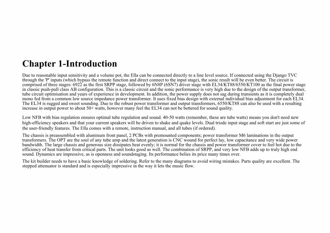
Wire layout: Most of the power supply wires run lengthwise along the chassis. Most signal wires and grounds run crossways. Try to keep power supply wires close to the chassis and running perpendicular (90 degrees) to signal and ground wires. Signal and ground wires can be a little above the chassis plane. Twisting together signal pairs and power supply pairs can also help to reduce hum and noise pickup. Do not twist signal and power supply pairs with each other. Pictures indicate which of the coloured wires to use.
Tips for Successful Kit BuildingRead each chapter through before starting it: You should familiarize yourself with the sequence of instructions before starting a chapter. Also, many chapters have helpful pictures and drawings scattered through them that will help you understand the written instructions.
Follow the sequence of instructions: These instructions were designed to make assembly as simple as possible and minimize interference between assembly steps.
Identify and measure parts: Be sure of the identity/value of each part before you install it. Many kit builders actually measure the value of resistors with a multimeter before installing them. Note: the parts in your kit may not look exactly like the ones pictured here as suppliers of parts are sometimes different. Some supplied values may differ slightly in value from circuit diagram and are within tolerance for the circuit.
Follow the schematic: It is a good idea to have the schematic diagram of the unit nearby and to compare the instructions with the schematic.
After installation, check the instructions again: Once a part is installed, double-check the installation against the printed instructions.
Check off each assembly page when completed
Chapter 4 – the Hardware1.It is highly recommended that you protect the front face before you start to avoid accidentally marking it during construction.
2.Turn the unit upside down and rest on a soft surface.
Remove the bottom cover.
3. mains wiring for your country is already done.
4. choke, high voltage to PS PCBs and bus wires between PCBs have been completed. Also the bridge rectifier supply for the remote control is done. See the following page and check that these connections are made

Chapter 5 – Input Connections1. connect L side RCA inputs to the selector module pcb as shown. Use the white teflon wire
2. connect the black ground bus wire across the RCA jacks as shown
3. connect the R side RCA inputs as shown. Use the shielded white wire. Shield of each wire connects to right side ground bus only. Other end of shield is not connected
4. make the 6 connections along the side of the selector board as shown to the attenuator and the small input pcb as shown
5. make the remaining connection from the ground point on the selector pcb as shown to the attenuator switch
6. make the connection to the small input pcb to the 1k resistor at the tube sockets as shown
7. Page following next has larger drawing for more detail


Chapter 6 – Power Transformer Connections1. check that choke connections from holes under small covers are already made to the bottom of the right and left PS PCB
2. check that connection wires from top of right pc pcb to top of left ps pcb is already made
3. check that wire pair from center hole under large cover to left side pcb is already made. These are the B+ supply wires (400V)
4. check that wires are connected to IEC input connector to switch on front as shown Check the ground connection to chassis at IEC connector is made as shown
5. check that the wire pair from center hole is connected to front edge of one ps pcb and then that a wire pair then connects to the same place on the opposite of the pcb. These are the bias voltage supply
6. connect the green, brown and blue wire prs to the tube socket pins as shown. These are 6v filament supply wires
7. check the connection of wire pr from center hole to the bridge rectifer. Confirm the capacitor connection. Note the '+' position and capacitor '+' match. Check the bridge rectifier to pcb connection as shown in the diagram.
8. install the LED as shown with supplied resistor in series


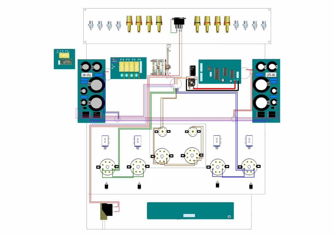
Chapter 7 – Output transformer Connections1. make the 0, 4, 8, 16ohm (black, blue, green, yellow) output wire connections to the speaker binding posts as shown using the wires from the
holes under the output transformers
2. connect the input side of the output transformers as shown:
1. white pr (drawn as light gray) to the outside tube sockets as shown connected to socket through 220r resistor
2. gray pr to the inside tube sockets as shown connected to socket through 220r resistor
3. orange and purple prs connected as shown
3. connect wire from bottom of each ps pcb to the tube socket indicated through the 43k and 51k resistors as shown
4. install the 1m and other wire connection shown at the two center octal tube sockets
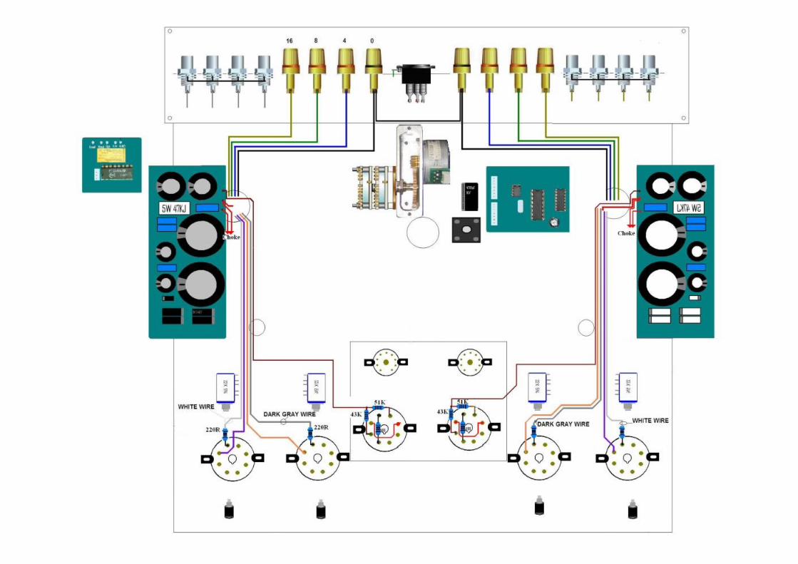

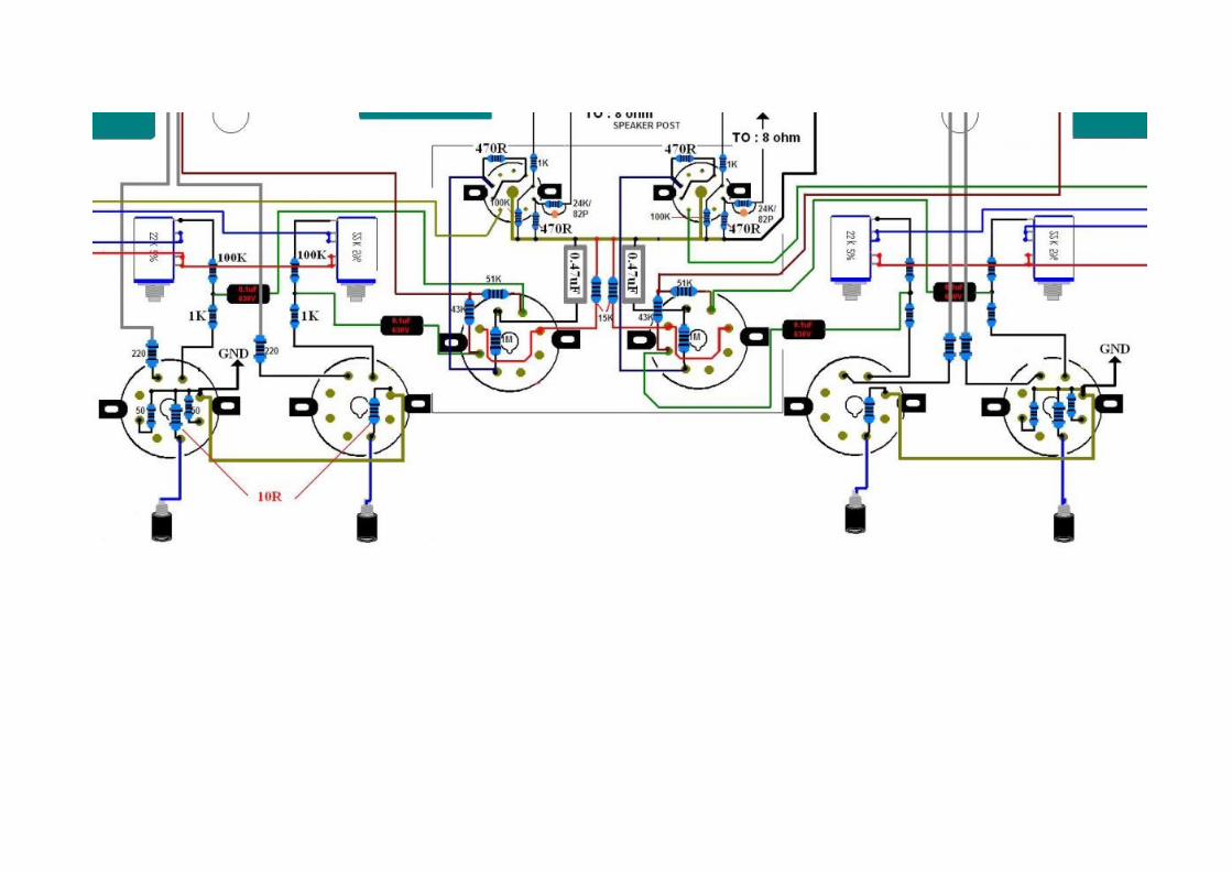
Chapter 8 – DC power supply and tube connections1. make connections from ps pcb to bias adjustment pots as shown
2. connect ps pcb to ground as shown
3. connect bias adjustment pots through 100k and 1k to tube sockets as shown
4. connect 0.1uf cap as shown and wire connections to tube sockets
5. connect 10r resistors as shown and to bias voltage test jacks
6. install the other parts as shown. Refer to detail on following page
7. note: nfb resistor/cap combination from pin 8 of small sockets connects to each 8ohm speaker out post


Note the ground bus bar as drawn in the diagrams to make connecting parts easier and better grounding. This is the bus bar as installed on the power tube sockets

this is the bus bar as installed on the signal tube sockets

bias pot connections


Chapter 9 – Operational notesDo not yet insert the tubes!1. Adjust the volume to lowest setting
2. Turn the chassis bottom facing up. Plug in the power and switch on the unit with the power switch. Watch for sparking, smoke or any condition that would indicate miswiring. If you have burned out a fuse, you can find a spare inside the little drawer in the IEC that slides out from the backside. If OK proceed to the next step. If not, check for mistakes.
3. Check power tubes, pin 5 (counting clockwise from the #1 pin indicated in the diagram) for -50VDC (-ve probe to ground buss, +ve probe to pin 5. (Since this is a negative voltage you may need to reverse the probes - check on a high range first). If lower than -50VDC, adjust bias pots to bring each pin 5 up to -50VDC.
4. Check the voltage between pins 2, 7 on each power tube for 6.3VAC 10%. AC range on your meter, one probe to pin 2, one probe to pin 7
5. Middle 4 tubes. 2 are 9 pin, 2 are 8 pin. Again counting clockwise from #1 pin. 8 pin tubes: As above for measuring ACV, check between tube pins 7 and 8 for 6.3VAC 10%
6. 9 pin tubes: Check pins 4/5 for 6.3vac 10%. One probe to pin 4, one to pin 5.
7. Check B+ on PS PCB for ~430v dc. Again to test DC V, -ve probe to ground buss, +ve (red) probe to test point. Turn off the power.
8. A: Turn over unit. Insert the 4 EL34 power tubes into A, B, C, and D.
8. B: Turn on power and connect black probe to ground. Put red probe into the bias check RCA socket in front of tube A and adjust closest bias pot until .4VDC is achieved. Repeat for other 3 power tubes Turn off power.
9. Double check all your connections and refer to the circuit diagrams at the back of the manual whilst doing so. Inspect all solder joints for completeness. Check carefully to make sure that small pieces of hardware or solder drops are not left inside the chassis. Reinstall chassis plate.
10. Turn unit over and insert the other tubes into their respective sockets (6922s and 6N8Ps). Do not connect input source and volume pot must be fully counter clockwise! To be safe you can attach a 10W 10 ohm resistor across each pair of speaker posts.
11. Turn on power. Adjust bias pot again for 0.4-0.45VDC. You may need to readjust several times until the amplifier stabilizes. Turn off the power.
12. Connect speakers and sound source (i.e. CD player). You should never operate the unit with no speaker load attached or with shorted speaker outputs whenever signal source is applied.
13. Turn on the power and input signal. Adjust volume pot to desired listening level.

1. Heater wire maximums: 5.7-6.9V
Distorted, low or poor quality sound1. Cathode bias is not .4-..5VDC
Blown fuse1. Metal debris has fallen inside chassis and is causing a short.
2. Output tube damaged.
3. Filter cap damaged.
4. PS transformer has shorted internally or has been miswired for local voltage.
Output tubes glow bright red1. PS voltage too high
2. Cathode bias not .4VDC-.5VDC
3. Output shorted or open when signal applied.
4. Old EL34s
Power Tube sets:1. EL34 bias at 0.4 to 0.45
2. KT88 and 6550 bias at 0.4 to 0.5
3. KT100 bias at 0.4 to 0.5 (make sure there is good airflow around tubes and chassis especially if higher setting on bias)
Bias is checked by putting one probe in the bias test jack and the other probe to the '0' speaker post. Voltage compares to ma, ie 0.4v = 40ma

Chapter 10 - Final Words and TweaksThe Ella requires about 50 hours running in especially if you are using new tubes.
Using more exotic NOS tubes can also improve and change the sound character of the amplifier.
Diodes on the screen: Some users have reported good results. Use 1a/1000v ie IN4007:
USE IN A WELL VENTILATED PLACE TO PROVIDE AIR CIRCULATION.
CopyrightThis manual is copyright of DIY HiFi Supply www.diyhifisupply.com . It must not be reproduced or distributed in paper or electronic form.
Manual produced by: DIY HiFi Supply Ltd www.diyhifisupply.com
rev3.7
Advanced kit builders may wish to experiment with connecting Ella’s output section to run in triode mode. A schematic diagram for this configuration is included below but not supported.

