elite biomedical solutionselitebiomedicalsolutions.com/site/assets/files/1071/bezel-hinge... · •...
TRANSCRIPT
Elite Biomedical Solutions Doc. No. 10119, Rev. C June 4, 2012
The manufacturers listed are the holders of their respective names and/or trademarks, and are not to be taken as an endorsement or affiliation with Elite Biomedical Solutions.
Page 1 of 4
Elite Biomedical Solutions
Bezel Hinge Pin Kit Installation Instructions
For Alaris® System Pump Modules Pump Module #8100
Elite Biomedical Solutions Part #30110
CAUTION
Utilize a static free environment when working on any electronic/electrical device.
• Separate Pump Module from PC Point of Care Unit.
• Remove four Phillips Head Screws, remove the Left and Right
IUI Connectors from the Rear Case and set aside.
• Remove two Phillips Head Screws and slide Rear Case back from the Pump Module Bezel to allow clearance for the Drill Fixture.
• Open Door and remove four Phillips Head Screws from Gray
Back Plate and set aside. • Disconnect Wire Harness Connector, remove Door and set aside.
• Inspect Upper Bezel Hinge area (typically broken) and ensure the
entire original Hinge Pin is removed. Utilize a sharp cutting edge if necessary.
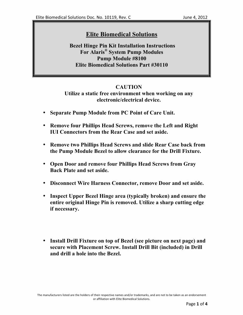
• Install Drill Fixture on top of Bezel (see picture on next page) and secure with Placement Screw. Install Drill Bit (included) in Drill and drill a hole into the Bezel.
Elite Biomedical Solutions Doc. No. 10119, Rev. C June 4, 2012
The manufacturers listed are the holders of their respective names and/or trademarks, and are not to be taken as an endorsement or affiliation with Elite Biomedical Solutions.
Page 2 of 4
• Remove Drill Fixture and remove any residual material.
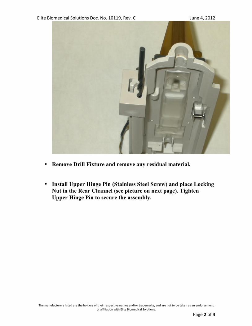
• Install Upper Hinge Pin (Stainless Steel Screw) and place Locking
Nut in the Rear Channel (see picture on next page). Tighten Upper Hinge Pin to secure the assembly.
Elite Biomedical Solutions Doc. No. 10119, Rev. C June 4, 2012
The manufacturers listed are the holders of their respective names and/or trademarks, and are not to be taken as an endorsement or affiliation with Elite Biomedical Solutions.
Page 3 of 4
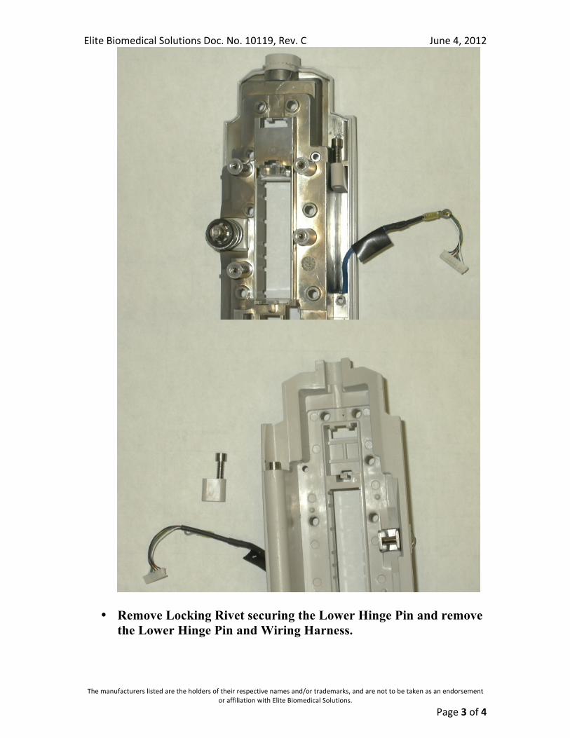
• Remove Locking Rivet securing the Lower Hinge Pin and remove the Lower Hinge Pin and Wiring Harness.
Elite Biomedical Solutions Doc. No. 10119, Rev. C June 4, 2012
The manufacturers listed are the holders of their respective names and/or trademarks, and are not to be taken as an endorsement or affiliation with Elite Biomedical Solutions.
Page 4 of 4
• The original Hinge Pin is installed around the Wiring Harness and will require removal (cutting off) to proceed. Use care in removal of Hinge Pin. Do not cut or nick Wiring Harness Assembly.
• Assemble the Replacement Lower Hinge Pin (halves) around the Wiring Harness and install into the Bezel and secure with Rivet.
• Install Rear Case of Pump Module, secure with two Phillips Head Screws and reinstall IUI Connectors; two Phillips Head Screws per connector.
• Install Door and connect Wire Harness Connector.
• Install Back Plate and four Phillips Head Screws.
• Perform all inspections to verify operation as outlined by the Manufacturer.
• Upon successful completion of testing, attach Pump Module to the PC Point of Care Unit.
• Perform all inspections to verify operation (complete unit) as outlined by the Manufacturer.
Always follow Manufacturers directions when servicing and testing instrumentation.
Elite Biomedical Solutions will warrant all Elite Biomedical Solutions replacement components for workmanship for a period of one year from date of purchase.
Components damaged from Customer misuse or abuse will not be covered.
For Technical Assistance, call 1-513-659-0993