eliminating an implant level impression...crown, extensive impaction of hardened bacterial and food...
TRANSCRIPT

88 Spring 2015 • Volume 31 • Number 1
Eliminating an Implant Level ImpressionCase Report of a Digitally Designed Implant Abutment

89 Journal of Cosmetic Dentistry
Howard
AbstractImplant dentistry has become a significant part of our daily practice. Today’s clinician has to be well versed in this area of dentistry and have increased knowledge to provide patients with the best possible treatment modality and successful result. This article presents one implant system’s method of delivering a patient-specific restoration that has the appropriate margin height and natural emergence contours for the patient while eliminating the need for an implant level impression. Because the gingival tissues were healed at the time of the healing abutment impression, the final abutment margin design has the ideal placement and contour relative to the alveolar and gingival tissues.
Key Words: healing abutment, digital design, patient-specific, traditional impression technique, esthetic outcome
The potential for clinical or laboratory error increases with the number of procedural and material components for each particular implant restorative case.
Nelson Y. Howard, DDS, AAACD
90 Spring 2015 • Volume 31 • Number 1
IntroductionImplant restorative dentistry has evolved over the years to become a simplified yet technique-sensitive process utilizing several different clinical steps along with, at times, multiple implant impression and re-storative components. The potential for clinical or laboratory error increases with the number of pro-cedural and material components for each particular implant restorative case.
Implant success has many different factors: selec-tion of the proper implant system to use for the par-ticular intraoral condition; accurate placement of the implant; management of the surrounding alveolar bone and gingival tissues; precise impression-taking procedures to create less disruption to these tissues; final restorative abutment design, material and type; and the final restoration design and selection.
Dental implants require healthy soft tissue mu-cosa for long-term osseous integration and successful maintenance of all components involved. A well-at-tached mucosal sulcus around the implant abutment is essential for limiting or reducing both oral cavity debris and bacterial infiltration into the surrounding tissue sulcus to the abutment-implant interface area.1
The BellaTek Encode Impression System (Biomet 3i; Palm Beach Gardens, FL) is designed to eliminate the need for implant level impressions, thereby help-ing to streamline the treatment process.2,3 With this system, it is not necessary to remove the healing abut-ment prior to the final placement of both the final abutment and restoration. Scanning codes embedded on the occlusal surface of the Encode healing abut-ment relay specific abutment design and computerized milling information. These codes also communicate the collar height, implant hex-orientation, platform diameter, and interface of the implant. With less dis-ruption of and to the peri-abutment mucosal sulcus interface, this delicate tissue around the implant is preserved with less trauma and the ability to achieve a well-sealed final abutment-to-implant interface is better maintained. The regular removal and replace-ment of the healing abutment during the entire im-plant restoration process has been shown to contrib-ute to the loss of crestal alveolar bone and negatively affect the peri-abutment mucosal sulcus tissues.4 The progression of crestal alveolar bone loss around the implant can lead to compromised restorative esthetics from exposed abutment and crown margins associat-ed with gingival recession surrounding the implant.5,6
The overall longevity of both implants and implant restorations has been attributed to well-fitting implant restorative components.7-11
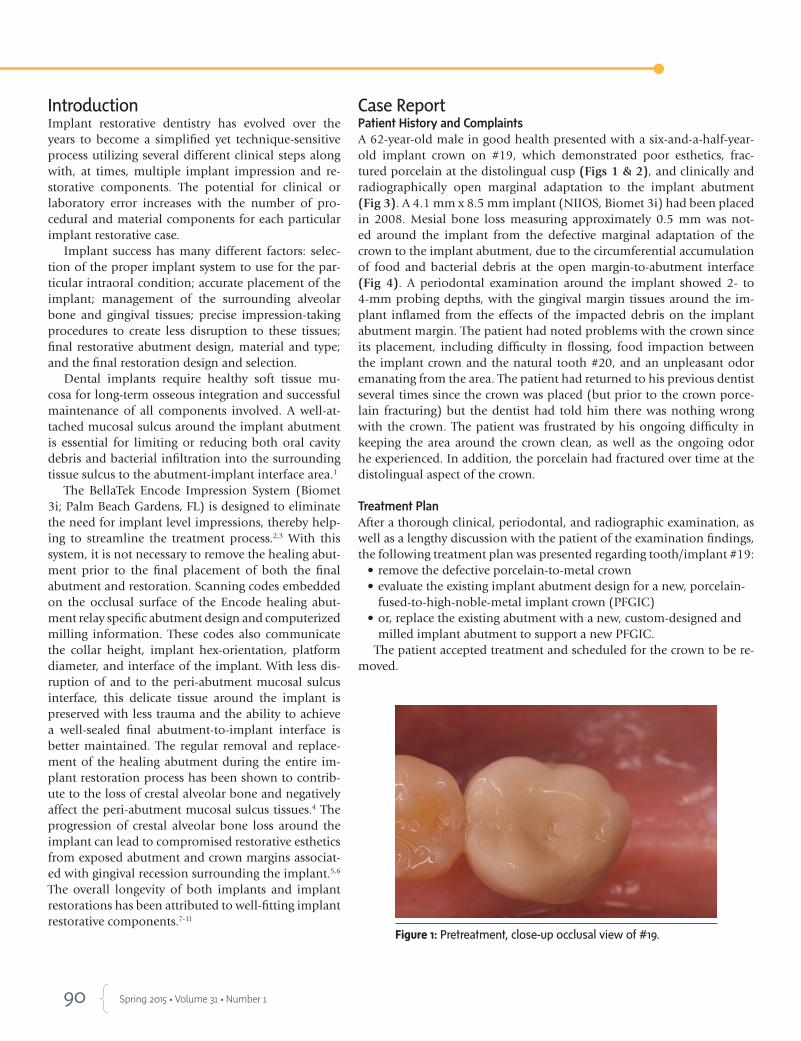
Case ReportPatient History and ComplaintsA 62-year-old male in good health presented with a six-and-a-half-year-old implant crown on #19, which demonstrated poor esthetics, frac-tured porcelain at the distolingual cusp (Figs 1 & 2), and clinically and radiographically open marginal adaptation to the implant abutment (Fig 3). A 4.1 mm x 8.5 mm implant (NIIOS, Biomet 3i) had been placed in 2008. Mesial bone loss measuring approximately 0.5 mm was not-ed around the implant from the defective marginal adaptation of the crown to the implant abutment, due to the circumferential accumulation of food and bacterial debris at the open margin-to-abutment interface (Fig 4). A periodontal examination around the implant showed 2- to 4-mm probing depths, with the gingival margin tissues around the im-plant inflamed from the effects of the impacted debris on the implant abutment margin. The patient had noted problems with the crown since its placement, including difficulty in flossing, food impaction between the implant crown and the natural tooth #20, and an unpleasant odor emanating from the area. The patient had returned to his previous dentist several times since the crown was placed (but prior to the crown porce-lain fracturing) but the dentist had told him there was nothing wrong with the crown. The patient was frustrated by his ongoing difficulty in keeping the area around the crown clean, as well as the ongoing odor he experienced. In addition, the porcelain had fractured over time at the distolingual aspect of the crown.
Treatment PlanAfter a thorough clinical, periodontal, and radiographic examination, as well as a lengthy discussion with the patient of the examination findings, the following treatment plan was presented regarding tooth/implant #19:
• remove the defective porcelain-to-metal crown • evaluate the existing implant abutment design for a new, porcelain-
fused-to-high-noble-metal implant crown (PFGIC) • or, replace the existing abutment with a new, custom-designed and
milled implant abutment to support a new PFGIC. The patient accepted treatment and scheduled for the crown to be re-
moved.
Figure 1: Pretreatment, close-up occlusal view of #19.

91 Journal of Cosmetic Dentistry
Clinical Findings and Treatment Protocol
Chairside ProceduresBlood pressure readings were taken prior to the administration of 1.8 ml 2% lidocaine with 1:100,000 epinephrine. After removal of the implant crown, extensive impaction of hardened bacterial and food debris was seen around the base of the abutment (Fig 5). Bacterial plaque ingrowth was also noted inside the abutment-to-implant interface after the abut-ment was removed. This bacterial plaque ingrowth was the result of an inaccurate microscopic abutment-to-implant connection that occurred at the time the abutment was placed. This particular implant uses the Certain Implant and Abutment System and QuickSeat Connection (both Biomet 3i). This connection produces an audible and tactile “click” that confirms placement of both abutments and impression copings. The extension-like projections or “fingers” at the bottom of the abutment provide added retention that engages the internal aspect of the implant, resulting in a “click” before the final seat screw is torqued into position (Fig 6).
Examination of the existing implant abutment (Fig 7) showed a short, conical, cylindrical-shaped design lacking proper anti-rotational support for a crown restoration. When evaluated against the patient’s opposing dentition, the abutment height clearance measured in excess of 4 mm. With 0.5 mm of metal coping and 2 mm of layered porcelain for strength considered the ideal standard, and based upon all the clinical findings, a mutual decision was reached to design a new, ideally designed implant abutment followed by the placement of a new PFGIC.
Figure 2: Pretreatment, retracted view of #19.
Figure 3: Pretreatment, periapical radiograph showing open mesial and distal margins of #19.
Figure 4: Occlusal view after PFM #19 was removed, showing a 360-degree ring of bacterial and food debris around the abutment margin.
Figure 5: Image after the abutment and debris were removed.
Figure 6: Implant abutment inner “fingers” at the implant connection zone.
Figure 7: Lateral view of existing abutment showing the short, conical, cylindrical-shaped design lacking proper anti-rotational support for a crown restoration.
The patient was frustrated by his ongoing difficulty in keeping the area around the crown clean...
Howard

92 Spring 2015 • Volume 31 • Number 1
Figure 8: Occlusal view of the abutment in the implant.
Figure 9: Periapical radiograph of the abutment in the implant to verify accurate placement prior to the final impression.
Figure 10: Final full-arch impression showing the abutment.
Figure 11: Close-up of the abutment in the final impression.
Cast MountingThe implant abutment was removed using a hand-held .48 hex driver tip, as it was not tightly held in place. The new abutment was placed manually (Fig 8) and a periapical radiograph was taken to confirm the correct seating placement into the implant (Fig 9). A full-arch vinyl polysiloxane impression was taken to accurately capture the position of the heal-ing abutment (Figs 10 & 11). The Stratos Articulator Facebow Transfer System (Ivoclar Vivadent; Amherst, NY) was used per the manufacturer’s specific labora-tory recommendations so the casts could be mounted with Adesso split mounting plates (Baumann Dental GmbH; Baden-Wurttemberg, Germany), also per the manufacturer’s recommendations. It is important pri-or to the cast mounting that the vertical occlusal pin rest on the incisal guide table and be set at zero so that the optical abutment scanner can read the codes on the healing abutment when the casts are mounted centered on the Adesso plates.1,2
The impression was sent to a dental laboratory, poured up in low expansion die stone,12 and mounted (Figs 12 & 13) per the manufacturer’s specific check-list and instructions for laboratories.
Figure 12: Close-up of a stone model of the abutment.
Figure 13: Lateral view of a stone model of the abutment.
LOCALIZED ARCH DELIVERY INTO PERIODONTAL POCKETSTHE PERIO TRAY® BY PERIO PROTECT:
MAKES ALL THE DIFFERENCE IN PATIENT RESULTS

KOIS DENTO-FACIAL ANALYZER
Visit us at the A.A.C.D. Annual Meeting www.panadent.com / 1-800-368-9777
Combining Esthetics & FunctionKOIS DENTO-FACIAL ANALYZER
Combining Esthetics & Function
• Simplicity• Versatility
• Predictability
Articulator SystemArticulator System

95 Journal of Cosmetic Dentistry
Figure 14: Abutment digital design, buccal-lingual view.
CAD/CAM Abutment DesignUsing the manufacturer’s online work order form, all aspects of the patient-specific, custom-milled abut-ment were designed by the author, with a design re-view request to be viewed prior to the final comple-tion by the manufacturer’s milling laboratory. The work order form was sent to this laboratory with the mounted models for design fabrication of the implant abutment (Figs 14-18).
Figure 15: Abutment digital design, buccal-lingual view.
Figure 16: Abutment digital design, buccal view.
Figure 17: Implant analog digital design, occlusal view.
Figure 18: Abutment digital design, occlusal view.
Howard
KOIS DENTO-FACIAL ANALYZER
Visit us at the A.A.C.D. Annual Meeting www.panadent.com / 1-800-368-9777
Combining Esthetics & FunctionKOIS DENTO-FACIAL ANALYZER
Combining Esthetics & Function
• Simplicity• Versatility
• Predictability
Articulator SystemArticulator System

96 Spring 2015 • Volume 31 • Number 1
Figure 19: Occlusal close-up view of the robotically-placed implant analog in the original stone model.
Figure 20: Lateral view of the final patient-specific abutment.
Figure 21: Occlusal view of the final patient-specific abutment.
Figure 22: View of the closed tray impression coping in the implant.
Figure 23: Laboratory analog attached to the closed tray impression coping in the final impression.
“Robotic” ReplacementWhen clinicians or laboratories use Encode’s healing abutments, they can request that Biomet 3i’s milling laboratory incorporate the placement of a lab implant analog into the stone model sent for scanning. The Robocast computer program, based upon the codes found on the occlusal aspect of the healing abutment used, precisely places the analog into the stone model to the exact depth, alignment, angulation, emergence profile, and position of the patient’s implant where the healing abutment was located on the stone mod-el (Fig 19). The Robocast “robot” also has the abil-ity to relieve the precise amount of gingival clear-ance around the abutment margins, based upon the requirements the clinician determines on the work order form. Although not a necessary requirement for fabrication of the final digitally designed implant abutment, the placement of the analog in the stone model is a distinctive feature of this system that does not require taking an implant level impression.
Upon review and acceptance of the abutment de-sign parameters, the final custom-designed and milled titanium abutment was completed and returned for patient try in (Figs 20 & 21).
Traditional ImpressionAt the time of the final impression, a comparison traditional impression technique was performed us-ing a standard closed tray implant impression coping placed in the implant (Fig 22). After removal from the implant, a matching implant analog was connected to the implant impression coping and placed accurately in the impression, according to the side groove pattern of the implant impression post (Fig 23). The impres-sion was poured up with a soft tissue material around the implant analog to replicate the gingival architec-ture present. This model aids the laboratory techni-cian by enabling comparison of the PFGIC emergence contours off the abutment margins as they appear in the mouth versus on the stone Robocast implant ana-log model from the milling laboratory.

97 Journal of Cosmetic Dentistry
Figure 24: Lateral view of the digitally designed milled abutment on robotic model.
Figure 25: Lateral view of the new abutment showing an ideal 2.5-mm occlusal clearance for the porcelain-fused-to-high-noble-metal (PFGIC) implant crown.
Howard
Final Abutment VerificationThe patient returned for a try in of the implant abut-ment (Figs 24 & 25) per the author’s specifications on the work order form. For ideal occlusal clearance between the top of the abutment and the opposing dentition, 2.5 mm of clearance is needed to compen-sate for 0.5 mm of PGFIC coping metal and 2.0 mm of layered porcelain. The new abutment was placed in the implant until a “click” was heard (Fig 26). A peri-apical radiograph was taken to verify the placement of the custom-milled abutment (Fig 27). A bite registra-tion of the new implant abutment was taken. Upon its intraoral removal, the new abutment was placed on the soft tissue laboratory comparison model and the position of the abutment was confirmed using the bite registration (Fig 28). The patient’s existing abutment and temporary were placed back on the implant, and the patient was scheduled for his final abutment and PFGIC placement. The model work and new bite reg-istration were sent to the laboratory along with final shade selection for the PFGIC.
Figure 26: Occlusal view of the abutment at patient try in. Figure 27: Periapical radiograph of the abutment at patient try in.
Figure 28: Bite registration on the traditional impression soft tissue model.

98 Spring 2015 • Volume 31 • Number 1
Final Placement Appointment At the final abutment and PFGIC placement ap-pointment, the patient’s temporary crown and existing implant abutment were removed. The internal aspect of the implant was cleaned with Concepsis (Ultradent Products; South Jordan, UT) in a microbrush applicator. The internal aspect was air-dried and microbrush-tip-dried before placing the digitally designed final im-plant abutment. The new abutment was placed in the implant until a “click” was heard, and the accompanying Certain Gold-Tite hexed abut-ment screw was torqued to 20 Ncm, as recom-mended by the manufacturer. The top of the hexed screw was covered with a small cotton pellet and sealed with a light-cured temporary filling material (Fermit, Ivoclar-Vivadent). The PFGIC restoration (Figs 29-32) was seated into position after all clinical margins to the abut-ment were verified, along with the interproxi-mal contact and occlusion to the opposing dentition. A periapical radiograph was taken to further verify the overall PFGIC-abutment-im-plant integrity (Fig 33). Upon confirmation of clinical and radiographic acceptance, the PFGIC was cemented to the new abutment with Temp Bond Clear (Kerr; Orange, CA) after Concepsis was applied. The abutment was then rinsed and air-dried.
Use of temporary cement initially with a cemented-to-the-abutment versus screw-re-tained crown allows the patient to evaluate the crown for form, function, and shading (if appli-cable) until the patient is completely satisfied. It also allows the clinician to retorque down the abutment screw, if necessary, after the pa-tient has had sufficient time to use the crown, without damaging the crown’s integrity. This is particularly important if the abutment were to become loose after the crown was cemented permanently, thus preventing an easier removal of the crown to reconnect the abutment to the implant. After a sufficient period of evaluation time, the final PFGIC can then be cemented per-manently to the Encode abutment.
Figure 29: Occlusal view of PFGIC on the Robocast model.
Figure 30: Lateral view of the PFGIC on the Robocast model.
The new abutment was placed manually and a periapical radiograph was taken to confirm the correct seating placement into the implant.

99 Journal of Cosmetic Dentistry
Figure 31: Lateral view of the PFGIC on the soft tissue model.
Figure 32: Close-up lingual view of the PFGIC abutment on the analog to verify marginal adaptation accuracy.
Figure 33: Periapical radiograph of the PFGIC abutment-implant connection.
The final implant PFGIC restoration dem-onstrated excellent esthetics, form, and con-tours (Fig 34). The patient was very pleased with the esthetic and functional outcome af-ter having endured years of odor and difficul-ty in flossing around the previous abutment and crown.
SummaryThis article described a simplified way to achieve a patient-specific, custom-milled implant abutment without having to use impression copings or implant level impres-sions. Encode is specific for Biomet 3i’s inter-nal and external hex implant systems and not applicable for every implant system currently available. In the case presented, the restorative outcome was easier and more efficient for the surgeon, laboratory technician, and restor-ative clinician, and more comfortable for the patient.
Acknowledgment
The author thanks Marc Hodges and Gretchen Wilson of Biomet 3i for their informational as-sistance and product support. He also thanks Julie Nichols, CDT, owner of Pearl Dental Studio (Es-condido, CA), for her excellent laboratory work in the fabrication of all the clinical models and final PFGIC restoration for the patient.
Howard
Figure 34: Lateral view of the final PFGIC restoration cemented in place.

100 Spring 2015 • Volume 31 • Number 1
References
1. Drago C, O’Connor G, Peterson T. Robot analog placement
and CAD/CAM abutments. J Dent Technol. 2009 Aug-
Sept;23-8.
2. Vafiadis DC. Computer-generated abutments using a cod-
ed healing abutment: a two year preliminary report. Pract
Proced Aesthet Dent. 2007 Aug;19(7):443-8.
3. Schupbach P, Glauser R. The defense architecture of the hu-
man periimplant mucosa: a histological study. J Prosthet
Dent. 2007 Jun;97(6 Suppl):S15-25.
4. Abrahamsson I, Berglundh T, Lindhe J. The mucosal bar-
rier following abutment dis/reconnection. An experimental
study in dogs. J Clin Periodontol. 1997 Aug;24(8):568-72.
5. Hartman GH. Initial implant position determines the
magnitude of crestal bone remodeling. J Periodontol.
2004 Apr;75(4):572-7.
6. Hartlev J, Kohberg P, Ahlmann S, Gotfredsen E, Andersen
NT, Isidor F, Schou S. Immediate placement and provision-
alization of single-tooth implants involving a definitive
individual abutment: a clinical and radiographic retrospec-
tive study. Clin Oral Implants Res. 2013 Jun;24(6):652-8.
DOI: 10.1111/j. 1600-0501.2012.02442.
7. Binon PP. Evaluation of machining accuracy and consisten-
cy of selected implants, standard abutments, and labora-
tory analogs. Int J Prosthodont. 1995 Mar-Apr;8(2):162-78.
8. Binon PP. The effect of implant abutment hexagonal mis-
fit on screw joint stability. Int J Prosthodont. 1996 Mar-
Apr;9(2):149-60.
9. Jemt T, Book K. Prosthesis misfit and marginal bone loss
in edentulous implant patients. Int J Oral Maxillofac Im-
plants. 1996 Sep-Oct;11(5):620-5.
10. May KB, Edge MJ, Russell MM, Razzoog ME, Lang BR. The
precision of fit at the implant prosthodontic interface. J
Prosthet Dent. 1997 May;77(5):497-502.
11. Byrne D, Houston F, Cleary R, Claffey N. The fit of cast and
premachined implant abutments. J Prosthet Dent. 1998
Aug;80(2):184-92.
12. De Bruyn H, Vandeweghe S. Increasing implant dentistry
in undergraduate education using new technology: A pilot
project. J Implant Reconstr Dent. 2010;2(1:)40-5.
Dr. Howard owns and operates private practices in San Marcos and Rancho Bernardo, California.
Disclosure: The author received material support from Biomet 3i for the impression and abutment parts mentioned in this article.
In the case presented, the restorative outcome was easier and more efficient for the surgeon, laboratory technician, and restorative clinician, and more comfortable for the patient.
Sources
BellaTek Encode Impression System: laboratory recommendations. West Palm Beach Gardens
(FL): Biomet 3i; 2012.
BellaTek Encode Impression System: optimization by design. West Palm Beach Gardens (FL):
Biomet 3i; 2013. jCD