elf magnetic field survey & assessment report
TRANSCRIPT

ELF Magnetic Field Survey & Assessment Report
of
Literature Building - 3000 University of California San Diego
for
University of California San Diego La Jolla, California
Report Date: January 24, 2009 FMS Ref: 2008-1020
FIELD MANAGEMENT SERVICES CORP.
123 North Laurel • Los Angeles, California 90048 Telephone (323) 937-1562 • Fax (323) 934-2101

NOTICE
All materials contained in this report are protected by copyright and may not be used by others. All content herein, including but not limited to text, graphics, and other intellectual property, cannot be reproduced except by permission of Field Management Services Corp. and provided that copyright notice appear in all copies and that both the copyright notice and permission notice appear in supporting documentation. Documentation contained in this report may not be reproduced, distributed, published, entered into a database, displayed, modified, used to create derivative works, transmitted, or exploited for distribution to others without the expressed written consent of Field Management Services Corp. Field Management Services Corp. has expressly prepared this report for the party noted as “Client”. Field Management Services Corp. shall be indemnified and held harmless from any losses, damages and costs with respect to the unauthorized use of any information contained in this report. Field Management Services Corp. is only responsible for the content of this report and reference to any other service or information source does not imply an endorsement by Field Management Services Corp.

Table of Contents
________________________________________
BACKGROUND:..........................................................................................................2
ELF OR AC MAGNETIC FIELD CHARACTERISTICS: ...............................................2
UNITS OF MEASURE: ................................................................................................4
SURVEY MEASUREMENT EQUIPMENT:..................................................................4
MEASUREMENT PROCEDURES: .............................................................................5
TEMPORAL VARIATIONS: .........................................................................................6
MEASUREMENT RESULTS: ......................................................................................7
NET CURRENT IMPLICATIONS:................................................................................8
MEASUREMENT OBSERVATIONS & CONCLUSIONS: ..........................................10
MITIGATION STRATEGIES: .....................................................................................12
MITIGATION OPTIONS: ...........................................................................................13
CLIENT RESPONSIBILITY: ......................................................................................16
TIME REQUIREMENTS: ...........................................................................................17
ACCEPTANCE AND GUARANTEE: .........................................................................17
COST: .......................................................................................................................18
Attachments
I. Site Photographs II. Figures 1 - 10
_________________________________________________________________
© 2009 Field Management Services Corp. - Los Angeles, California

FIELD MANAGEMENT SERVICES CORP 123 North Laurel • Los Angeles, California 90048 Telephone (323) 937-1562 • Fax (323) 934-2101 DATE: January 24, 2009 FMS REF: 2008-1020 CLIENT: University of California San Diego 9500 Gilman Drive
La Jolla, California 92093 ATTN: Daphne Thaung, MPH, CIH Occupational Health & Hygiene Manager PROPERTY: Literature Building - 3000
University of California San Diego La Jolla, California
PROJECT: ELF Magnetic Field Survey SCOPE: The scope of this project involved measurement of the magnitude and vector direction of power frequency magnetic fields and data analysis as necessary for development of a plan to mitigate magnetic field levels with estimated costs and time to implement remediation measures. Submitted by: FIELD MANAGEMENT SERVICES CORP.

UCSD Literature Building - EMF Survey Pg. 2 January 24, 2009
Field Management Services
BACKGROUND: This report documents results of an Extremely Low Frequency (ELF) magnetic field survey authorized by the University of California San Diego (UCSD) and conducted by Field Management Services (FMS) of areas adjacent to electrical facilities which support operation of hydraulic elevators in a structure known as the “Literature Building – 3000” located on the UCSD Campus in La Jolla, California. Evidently, spot measurements by others indicate that magnetic field levels ranging from 2 to 6.5 mG are present in adjacent areas during peak surges when elevators are in operation. To gain a better understanding of conditions present and to develop possible mitigation solutions if appropriate, FMS recommended that a thorough ELF magnetic field assessment be conducted. On December 22, 2008 an FMS technical representative visited the UCSD site and with the assistance of Richard Moore, Power Testing and Energization, Inc., conducted a detailed magnetic field survey to measure, document and further characterize ELF magnetic fields present in the areas of interest. To inform the reader, the following general information is provided regarding ELF or AC magnetic fields.
ELF OR AC MAGNETIC FIELD CHARACTERISTICS: ELF or AC magnetic fields are naturally emitted by current-carrying electrical conductors and devices. The ELF magnetic field strength emitted by electrical circuits is directly proportional to the magnitude of electrical current. However, multiple conductor cables carrying balanced currents have a low net emission, a consequence of the natural cancellation of magnetic fields created by currents traveling in opposite directions (or with different phase angles) in adjacent conductors. Rigid metallic conduit generally provides good magnetic field reduction, provided that the feed and return currents are equal, in single-phase circuits, and if all of the currents (both feed and return) are present, in multi-phase circuits.
UCSD Literature Building - EMF Survey Pg. 3 January 24, 2009
Field Management Services
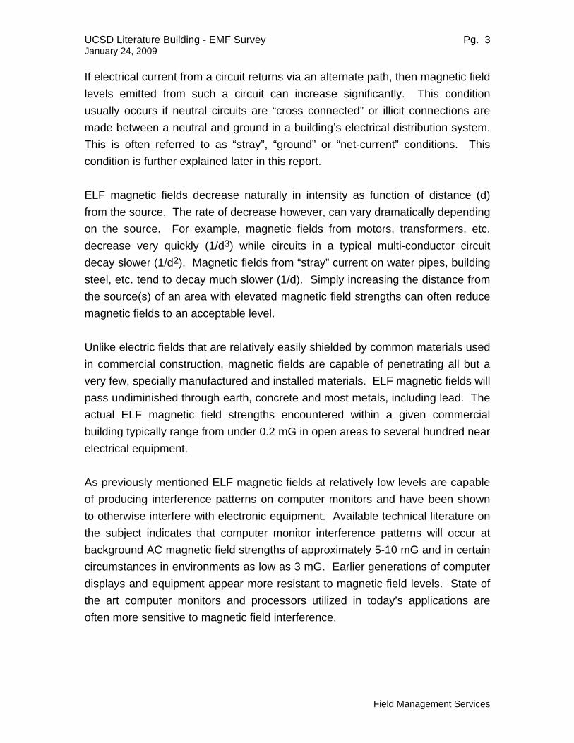
If electrical current from a circuit returns via an alternate path, then magnetic field levels emitted from such a circuit can increase significantly. This condition usually occurs if neutral circuits are “cross connected” or illicit connections are made between a neutral and ground in a building’s electrical distribution system. This is often referred to as “stray”, “ground” or “net-current” conditions. This condition is further explained later in this report. ELF magnetic fields decrease naturally in intensity as function of distance (d) from the source. The rate of decrease however, can vary dramatically depending on the source. For example, magnetic fields from motors, transformers, etc. decrease very quickly (1/d3) while circuits in a typical multi-conductor circuit decay slower (1/d2). Magnetic fields from “stray” current on water pipes, building steel, etc. tend to decay much slower (1/d). Simply increasing the distance from the source(s) of an area with elevated magnetic field strengths can often reduce magnetic fields to an acceptable level. Unlike electric fields that are relatively easily shielded by common materials used in commercial construction, magnetic fields are capable of penetrating all but a very few, specially manufactured and installed materials. ELF magnetic fields will pass undiminished through earth, concrete and most metals, including lead. The actual ELF magnetic field strengths encountered within a given commercial building typically range from under 0.2 mG in open areas to several hundred near electrical equipment.
As previously mentioned ELF magnetic fields at relatively low levels are capable of producing interference patterns on computer monitors and have been shown to otherwise interfere with electronic equipment. Available technical literature on the subject indicates that computer monitor interference patterns will occur at background AC magnetic field strengths of approximately 5-10 mG and in certain circumstances in environments as low as 3 mG. Earlier generations of computer displays and equipment appear more resistant to magnetic field levels. State of the art computer monitors and processors utilized in today’s applications are often more sensitive to magnetic field interference.

UCSD Literature Building - EMF Survey Pg. 4 January 24, 2009
Field Management Services
The possible effects of ELF magnetic fields on human health have been extensively studied.. FMS, by virtue of this report, makes no attempt to attribute value to either side of the question regarding risk to human health nor, for the purposes of health or safety, does the company assign value to any particular magnetic field levels. The US Department of Energy RAPID Program WEB site (www.niehs.nih.gov/emfrapid) and the World Health Organization (www.who.int/peh-emf) are excellent sources for comprehensive information on the EMF health issue. UNITS OF MEASURE: Magnetic flux densities (B) are reported using units of gauss (G). However, it is usually more convenient to report magnetic field levels using milligauss (mG) which is equal to one-thousandth of a gauss (i.e., 1 mG = 0.001 G). Some technical reports also use the unit Tesla (T) or microtesla (.µT); (1 .µT = 0.000001 T) for magnetic flux densities. The conversion between these two units is 1 mG = 0.1µT and 1 µT = 10 mG. SURVEY MEASUREMENT EQUIPMENT: To record ELF magnetic field values, the following equipment was utilized: Instrument Manufacturer Model Serial No.
Gauss Meter Dexsil Fieldstar 1000
Magnum 310
31400324
9870535
ELF magnetic field measurements were taken using a Dexsil Fieldstar 1000 Gauss meter and a Dexsil Magnum 310 Gauss meter. The meters take readings in three orthogonal planes and calculate the resultant field (square root of the sum of the squares) for the measurement point in space.

UCSD Literature Building - EMF Survey Pg. 5 January 24, 2009
Field Management Services
The Field Star 1000 and Magnum 310 are computer-controlled, three-axis, ELF exposure meters. Each of the three-axis sensors measures the magnetic field and the on-board computer calculates a resultant field value. The resultant is comparable to a maximum field value and is calculated as the square root of the sum of the squares for all three orthogonal axes Br = √Bx² + By² + Bz². All magnetic field measurements in this report are the RMS (root mean square) values. The Dexsil Magnum 310 was used to take spot measurements at selected locations around the Literature Building Ground Floor Electrical & Elevator Rooms. These measurements were used to establish the locations for timed measurements using the Field Star 1000. The Field Star 1000 meter also contains an internal sampling mode wherein measurement values can be stored at intervals of 1 second or any number of minutes between 1–15. For this study, the meter was set to record timed data at the rate of 1 sample per second. At the conclusion of a measurement session, a file name was created, which describes the conditions of the test location, and the data uploaded to a laptop computer that is equipped with interface software. MEASUREMENT PROCEDURES: For this survey, measurement procedures consistent with test protocols and techniques described in ANSI/IEEE Standard 644-1994 & C95.6-2002, IEEE Recommended Practices for Measurement of Electric and Magnetic Fields from AC Power Lines were utilized. As a first measure, spot measurements were taken in areas of interest to determine the presence of magnetic field levels.
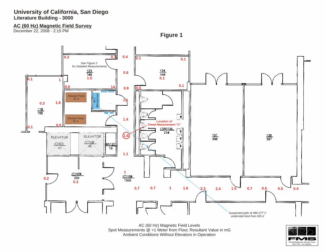
• As shown on attached Figure 1, magnetic field spot measurements were first taken throughout occupied areas including hallways, adjacent to the Literature Building’s Ground Floor electrical & elevator equipment room at a constant height of one meter above floor level. At the request of UCSD representatives, similar spot magnetic field measurements were taken as shown in Figure 8, in occupied areas of the Second Floor electrical room which is immediately above the Ground Floor electrical room.

UCSD Literature Building - EMF Survey Pg. 6 January 24, 2009
Field Management Services
• Based on spot measurements noted in Ground Floor Room 123 which is immediately adjacent to electrical and elevator equipment, supplemental ELF magnetic field readings were taken in a regular pattern on an "x" and "y" grid of two feet equal spacing as illustrated on attached Figure 2, to provide a more detailed view of magnetic field conditions present in the room.
• To establish ambient, base state magnetic field conditions, spot magnetic
field measurements in Figures 1,2 & 8 were taken without the two adjacent hydraulic drive elevators in operation.
• To determine to what extent ELF magnetic field conditions may
momentarily increase in adjacent areas when the elevators are operating, timed magnetic field measurements were taken at three locations noted on Figures 1 & 2. Timed measurements utilizing a 1 second sample rate were then conducted at each of the three locations while a UCSD facilities representative utilizing the elevator control equipment, simultaneously and constantly cycled each elevator in varying lifting and descending sequences to emulate a “busy” elevator operation condition.
TEMPORAL VARIATIONS: ELF magnetic field spot readings taken during magnetic field surveys are accurate only for the specific point in time that they were taken. Magnetic field strengths emanating from electrical equipment such as is adjacent to the measured areas of the Literature Building, will vary with the electric (current) load. It was noted during the December 22, 2008 survey, that the Literature Building appeared to be sparsely occupied; no doubt due to the Holiday period. Also, external weather conditions were relatively cool. It is the observation of FMS based on prior experience and observation that it is possible that magnetic field conditions at other times of the year in the Literature Building may be somewhat higher or lower and will vary in relation with the amount activity in the building and ambient external conditions.

UCSD Literature Building - EMF Survey Pg. 7 January 24, 2009
Field Management Services
MEASUREMENT RESULTS: ELF magnetic field measurements, utilizing the previously described procedures, were conducted at the Literature Building site on December 22, 2008 commencing at approximately 2:00 pm and ending at approximately 4:30 pm. The measurement data has subsequently been reviewed, analyzed and is summarized hereafter and on the attached Figures 1 through 8.
• Figure 1 is a partial Ground Floor plan of the Literature Building annotated with spot magnetic field measurement data. Spot measurements at incremental distances were noted for portions of both the north/south and east/west hallways. The measurements appear to confirm the approximate location and path of the under slab 480/277V feed to the building’s main breaker panel, MS-3.
• Figure 2 is a floor plan of Room 123 annotated with 2’ x 2’ measurement
grid values. Note that the peak of 44 mG and higher values are located in the southeast corner of the room which is closet to the adjacent main electrical service and two distribution breaker panels.
• Figure 3 is a 3D plot of the grid measurements taken in Room 123 which
allows a visualization of field conditions throughout the room. Note that fields decay rapidly within 4 to 6 feet of the peak value and become less than the 2 mG throughout most of the room’s area.
• Figure 4 contains plots of timed Bres measurements at three locations
with both elevators continuously cycling up and down during the recording period of approximately 3 to 5 minutes. Note that the largest increase of field strength from 35 mG to 44 mG occurred at the spot measurement peak location in Room 123, nearest to the adjacent main and distribution breaker panels. Increases of approximately 4 mG were apparent at the other two timed measurement locations.

UCSD Literature Building - EMF Survey Pg. 8 January 24, 2009
Field Management Services
• Figure 5, 6 & 7 contain plots of the x, y & z axis timed measurement data at the three locations with both elevators continuously cycling during the recording periods.
• Figure 8 is a partial Second Floor plan of the Literature Building
annotated with spot magnetic field measurement data. Spot measurements within Room 223 indicate values ranging from 1.4 mG to 96 mG in areas nearest to electrical equipment in the adjacent Second Floor Electrical Room. ELF magnetic field values were generally <2 mg throughout the majority of Room 223 and in the adjacent hallway.
NET CURRENT IMPLICATIONS: Design of an effective magnetic field reduction strategy requires an understanding of the various magnetic field sources present. The process of gaining such an understanding can be simplified by grouping the magnetic field sources into two categories: (1) spatial magnetic fields, and (2) net-current magnetic fields. In a typical ac circuit, if the vector sum of the phase currents and the neutral (and/or ground wire if present) add to zero, the magnetic field at a distance from the circuit will be solely due to the differences in distance and direction from the point of measurement to the individual source conductors and the current contained in the circuit. Magnetic fields produced as a result of conductor separation and the consequent decrease of natural flux cancellation are known as spatial magnetic fields. Spatial magnetic fields typically decay with the distance (source to point of measurement) squared, 1/d2. Effective mitigation measures may include shielding, reconfiguration of the conductors so as to maximize cancellation, and/or moving all conductors so as to increase distance. In multi-grounded four-wire electric utility distribution and transformer systems, and in many industrial and commercial building-wiring systems, some portion of the neutral current may return to the source transformer via illicit building ground connections.

UCSD Literature Building - EMF Survey Pg. 9 January 24, 2009
Field Management Services
In other cases, neutrals of different circuits may be connected together, thus allowing current from one neutral to return to the transformer via alternate neutral conductors. In any of these instances, the vector sum of the currents for any given circuit may not add to zero. When the vector sum of the phase, neutral, and parallel ground wire (if present) for a given circuit does not equal zero, a “net-current” condition is present. This circuit condition creates net-current magnetic fields. Although net-current magnetic fields also decay with distance, the rate of decay is less effective, 1/d versus 1/d2. When net-current conditions are present, the fields caused by net currents cannot be shielded by conventional means and reconfiguration of conductors is usually not effective at reducing net-current magnetic fields. In general, the best mitigation measure for magnetic fields caused by a net-current condition is to correct wiring problems (improper neutral connections, missing neutrals, improper grounding, etc.) so as to minimize the net-current. After this work is complete, the residual, spatial fields can be shielded. One or more of the following may cause net-current conditions:
1. The sum of all secondary phase currents must return to the source transformer via the neutral and/or earth ground. The earth ground may consist of physical wires (bare or green) but also includes water pipes, structural steel, reinforced concrete, etc. Current that returns via the various ground paths rather than the neutral conductor results in a net-current equal in magnitude to the ground current.
2. Where multiple circuits are present, the neutrals for the circuits
may be physically connected through improper common ground connections. Current on one neutral may thus be diverted to other neutrals via the ground path. In this case, both circuits will have a net-current. Multi-grounded circuits are common for utility overhead and underground distribution circuits but are generally not allowed by the National Electric Safety Code for customer (residential, commercial, industrial) wiring.

UCSD Literature Building - EMF Survey Pg. 10 January 24, 2009
Field Management Services
3. Multi-point grounding may also result in ground loops in which net currents circulate in closed loop ground paths without returning to the source transformer. In other words, it is possible to have net-currents within a portion of wiring even if the net-current at the source is zero. Once again, ground loops can be eliminated or significantly reduced by using single point grounding.
The ANSIIEEE magnetic field survey procedure utilized by FMS for the measurement of ELF magnetic field conditions within the Literature Building areas of interest; provide a fairly comprehensive view of magnetic fields emanating from the adjacent electrical distribution equipment. As magnetic fields generally diminish in a linear manner (1/d2) throughout the Room 123 grid measurement area, it is likely that the magnetic fields are spatial in nature. MEASUREMENT OBSERVATIONS & CONCLUSIONS: The following conclusions are offered after a review by FMS of the data from the December 22, 2008 ELF magnetic field survey of the UCSD Literature Building ground floor area of interest
• The source of ELF magnetic field levels noted in limited areas and rooms adjacent to the Ground Floor elevator equipment and electrical room are principally emanating from the 800 amp main electrical distribution panel MS-3 and the under slab 480-277V feed circuit to the MS-3 Panel. ELF magnetic fields from the two distribution breaker panels in the electrical room also contribute to the ELF magnetic field emission profile of the electrical room equipment. The measurement data demonstrates that magnetic fields from the electrical equipment generally decay at the anticipated 1/d2 rate.
• ELF magnetic field emissions from the two EL-3 and EL-4 elevator
hydraulic pump and equipment enclosures in the elevator equipment room are minimal. Magnetic fields from the pump motors decay very rapidly at a 1/d3 rate and are nominal in adjacent occupied areas. ELF magnetic field emissions from the feed and control circuits in each elevator’s pump

UCSD Literature Building - EMF Survey Pg. 11 January 24, 2009
Field Management Services
enclosure although decaying slower at the1/d2 rate are minimal and are further attenuated by the steel equipment enclosure. The elevator pumps and control equipment as such, should then not be viewed as significant magnetic field emission sources. Rather, the varying electrical load (30 to 40+ amps) generated by each pump when operating, is contributory to the total loading condition present in the MS-3 main panel, which is the primary source of magnetic field emissions.
• The measurement data confirms that relatively short duration increases in
electrical loading in the MS-3 main distribution panel caused by cycling of the elevator hydraulic pumps, causes a like short duration increase in the ELF magnetic field environment in areas immediately adjacent to the Ground Floor electrical room. It must be noted however that increases in magnetic field level due to operation of the elevators occur only in the adjacent Room 123 and in a limited area of the hallway adjacent to the Ground Floor electrical room. Increases in the MS-3 magnetic field profile caused by operation of the elevators, appear to decay sufficient so as to not cause material increases of magnetic field levels in other occupied offices in the general area of the Ground Floor electrical room.
• A close examination of all the measurement data, in particular the grid
defined Room 123 measurements, generally indicates that magnetic fields decay consistent with a 1/d2 rate associated with typical electrical circuits. This suggests that net-current circuit conditions, if present, are negligible.
• Spot ELF magnetic field measurements taken in select areas of the
Second Floor Room 223 indicate that levels are generally < 1 mg and are likely not from electrical equipment located immediately beneath. Rather, ELF magnetic fields in Room 223 are from electrical equipment located in an adjacent small Electrical Room. ELF magnetic field levels > 90 mG were noted in a limited area of the room immediately adjacent to an electrical transformer located in the adjoining Electrical Room, but rapidly decay at the 1/d3 rate associated with transformers; to levels < 2 mG with a few feet of the wall

UCSD Literature Building - EMF Survey Pg. 12 January 24, 2009
Field Management Services
• In sum, measurement data indicates that only limited areas Room 123 and
Room 223 have ELF magnetic field levels present that are modestly higher than the background magnetic field; a consequence of close adjacency to electrical distribution equipment. ELF magnetic field levels measured outside these areas were generally consistent with ambient ELF magnetic field levels typically present in office buildings. If UCSD decides to reduce ELF magnetic fields in these two rooms, the following mitigation options may be considered to reduce magnetic field strengths to near ambient conditions present throughout the building.
MITIGATION STRATEGIES: Often, combinations of the following strategies are employed to reduce ELF magnetic field strengths in an affected area such the Literature Building Room 123 & 223 which are immediately adjacent to high current electrical equipment.
1. Increase Distance ELF magnetic fields decrease naturally in intensity as a function of distance (d) from the source. The rate of decrease however, can vary dramatically depending on the source. For example, magnetic fields from motors, transformers, etc. decrease very quickly (1/d3) while circuits in typical conduit decay slower (1/d2). Simply increasing the distance from the source(s) to an area with elevated magnetic field strengths can often reduce fields to an acceptable level.
2. Decrease the Source Strength Any decrease in magnetic field
strength produced by an offending source such as a power panel, will proportionately reduce the field strengths in the affected area. In some instances, changes or alterations can be made to electrical equipment that will improve or enhance the natural cancellation inherent in circuits by compacting or rearranging the opposing circuit conductors.

UCSD Literature Building - EMF Survey Pg. 13 January 24, 2009
Field Management Services
3. Shielding of Source or Area If acceptable reductions in magnetic
field strengths in affected areas are not possible by increasing distances or decreasing source field strengths, it is often possible to reduce field strengths by the design and installation of magnetic field shielding utilizing ferrous and/or conductive materials.
MITIGATION OPTIONS: If UCSD wishes to mitigate the modest levels of ELF magnetic field levels in Rooms 123 and 223, FMS suggests that UCSD consider a magnetic field mitigation scheme. Given the transitory nature of the hallway adjacent to the Ground Floor electrical/elevator equipment rooms, it does not seem necessary or prudent to consider mitigation measures to reduce modest field levels which are present in limited areas. It would be highly unusual for either people or sensitive equipment to be located in these areas for any significant period of time as opposed to an office or work space such as Room 123 or 223. Increasing Distance Theoretically, it is of course feasible to consider relocation of the MS-3 main distribution panel in the Ground Floor electrical room to an alternate location sufficiently distance from any occupied work space. Such relocation would certainly be cost prohibitive and present significant disruption and implementation challenges. However, using the December 22, 2008 magnetic field spot measurement information as a guide, consideration may also be given to reconfiguring Office 123 and such that the occupant(s) as well as sensitive equipment are located in areas with lower magnetic fields present. Decrease the Source Strength It also does not appear possible to meaningfully lower magnetic field conditions in the subject offices by any changes to the adjacent electrical equipment.

UCSD Literature Building - EMF Survey Pg. 14 January 24, 2009
Field Management Services
Shielding of the Offices It is the opinion of FMS based on considerable experience with similar facilities, that in order to achieve reductions of magnetic fields in Room 123 and 223 it will be necessary to install a magnetic field shielding scheme in each room, utilizing special conductive materials. Such highly conductive shielding material may be utilized to achieve a very high degree of shielding efficiency by the induction of eddy-currents that occur within conductive materials when placed in an ELF magnetic field. AC electrical currents are induced within the conductive material in closed circular paths which are perpendicular to the inducing external magnetic field. Such induced eddy-currents oppose changes in the inducing external magnetic field and as a result, ELF magnetic fields produced by the circulating eddy-currents cancel the larger external ELF magnetic fields near the conductive material surface. Implemented correctly, this technique results in a very high degree of shielding efficiency. While it is theoretically possible to install shielding behind all of the electrical distribution equipment inside of the Ground Floor Electrical Room; such an installation would be extremely difficult, disruptive and inordinately costly, as the MS-3 electrical service panel and distribution panels would have to be temporarily removed to permit installation of shielding material behind the equipment. Alternately, FMS recommends that consideration be given to installation of shielding material in the affected Room 123 area. Attached to this report, as Figure 9, is a floor plan diagram which illustrates location of recommended shielding installation scheme. As shown on Figure 9, FMS recommends that a continuous plane of conductive shielding material be installed on the south office wall which is common to the adjacent electrical room. This shielding, consisting of a single layer, would be installed from floor slab to the finished ceiling height. Note also that for optimum performance, shielding is also recommended for installation on portions of the intersecting north and south walls. Lastly, as indicated on the attached Figure 9 shielding diagram, a single layer of conductive shielding is recommended for installation directly on the entire floor of Room 123.

UCSD Literature Building - EMF Survey Pg. 15 January 24, 2009
Field Management Services
In a like manner, installation of conductive shielding is recommended to lower ELF magnetic field levels present in Room 223. In this instance as shown on attached Figure 10, is appears possible to install a continuous layer of shielding in the adjacent Electrical Room on the common wall with Room 223. The shielding as shown, would be installed from floor level to a height of approximately eight feet. Also, it will be necessary to install a layer of conductive shielding on a portion of the Electrical Room wall, beneath the existing transformer. In preparation for the shielding installation, all furnishings and equipment must be temporarily removed from Room 123. UCSD Facilities Department and/or its designated contractor will be required to install a layer of ¾” plywood on designated portions of the existing wall surface in Room 123 and in the Second Floor Electrical Room, to provide a mounting substrate for the shielding material. The contractor will also have to provide for either temporary removal or support of the Second Floor Electrical Room transformer to allow installation of shielding material on the existing floor slab beneath the transformer’s location. After placement and mechanical fastening on floor and wall surfaces, shielding plates are bonded together utilizing a specialized FMS welding procedure. The magnetic field shielding material may be penetrated with small openings to accommodate electrical, plumbing and other requirements. These small penetrations and openings will not compromise performance of the shielding material. Installation of the floor shielding material will add approximately ¼ inch to the floor elevation. A layer of drywall may be reinstalled on wall shielding surfaces by use of adhesive, to restore room finish. Based on available data, FMS believes that the installation of shielding material will result in significant reductions of magnetic field strengths in the affected office areas, absent the presence of any net-current conditions. It must also be understood that, unless unreasonably expensive design precautions are employed, any mitigation plan will have the potential for small areas with slightly elevated values.. These small areas, if present, are typically at the extreme perimeter of the shielded area and away from areas normally occupied by people or sensitive equipment. These locations, if any, would be identified in the post mitigation survey. FMS design approach, absent specific instructions to the

UCSD Literature Building - EMF Survey Pg. 16 January 24, 2009
Field Management Services
contrary, assumes that the cost of such precautions is not justified and that reasonable operations and occupation alternatives, within the overall project objectives, are available. CLIENT RESPONSIBILITY: In the event that the previously described magnetic field shielding scheme is to be implemented by FMS, it will be necessary for the UCSD to provide the following preparations prior to installation.
1. Temporarily remove existing furnishings including equipment from the Room 123 area designated for shielding installation.
2. Remove existing carpeting for the floor area designated for
installation of shielding material which must mount directly to the floor slab. Reinstall new floor finish after installation of shielding.
3. Install a layer of ¾ inch plywood installed on the designated wall
surfaces (Room 123 & Second Floor Electrical Room) to provide a mounting substrate for the installation of shielding material. Installation of new layer of drywall on shielding to restore room finish
4. To facilitate the bonding process of the shielding material panels,
it will be necessary to provide temporary power in the area. Provide a three-phase 208 V, 30 amp, 3-pole, 4-wire twist lock connector grounding electrical outlet (NEMA-L15-30R).
5. As the welding procedure utilized to bond the shielding materials
produces a small amount of smoke, provisions must be made to temporarily disable or turn off, any smoke or fire detection systems in the immediate area of the work during the bonding process. An adequate fan or temporary exhaust system must be provided to ventilate the office area.
UCSD Literature Building - EMF Survey Pg. 17 January 24, 2009
Field Management Services
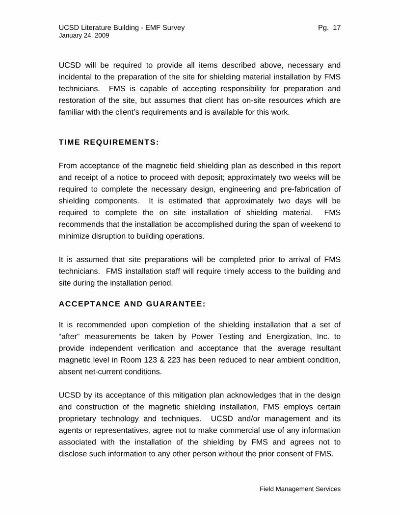
UCSD will be required to provide all items described above, necessary and incidental to the preparation of the site for shielding material installation by FMS technicians. FMS is capable of accepting responsibility for preparation and restoration of the site, but assumes that client has on-site resources which are familiar with the client’s requirements and is available for this work. TIME REQUIREMENTS: From acceptance of the magnetic field shielding plan as described in this report and receipt of a notice to proceed with deposit; approximately two weeks will be required to complete the necessary design, engineering and pre-fabrication of shielding components. It is estimated that approximately two days will be required to complete the on site installation of shielding material. FMS recommends that the installation be accomplished during the span of weekend to minimize disruption to building operations. It is assumed that site preparations will be completed prior to arrival of FMS technicians. FMS installation staff will require timely access to the building and site during the installation period. ACCEPTANCE AND GUARANTEE: It is recommended upon completion of the shielding installation that a set of “after” measurements be taken by Power Testing and Energization, Inc. to provide independent verification and acceptance that the average resultant magnetic level in Room 123 & 223 has been reduced to near ambient condition, absent net-current conditions. UCSD by its acceptance of this mitigation plan acknowledges that in the design and construction of the magnetic shielding installation, FMS employs certain proprietary technology and techniques. UCSD and/or management and its agents or representatives, agree not to make commercial use of any information associated with the installation of the shielding by FMS and agrees not to disclose such information to any other person without the prior consent of FMS.

UCSD Literature Building - EMF Survey Pg. 18 January 24, 2009
Field Management Services
ELF magnetic field spot readings taken during surveys are accurate only for the specific point in time that they were taken. Magnetic field strengths emanating from electrical equipment such as is adjacent to the subject area will vary with the electric current (load). However if any physical alterations occur in the future to the existing electric system such as the addition of conduits or wire-ducts passing through or above the subject area, physical changes to the service equipment which create load imbalances, increased conductor separations and/or net current conditions, or other electric wiring alterations in adjoining areas, and inasmuch as FMS has no control over such possible changes, FMS cannot warrant that ELF magnetic field strengths will remain within the after readings at any future date after completion and acceptance of the shielding installation. COST: Cost for implementing the shielding scheme as previously described intended to reduce the elevated ELF magnetic fields at the UCSD, Literature Building site is: Installation of Magnetic Field Shielding – Room 12 $ 24,550 Installation of Magnetic Field Shielding – 2nd Floor Electric Room $14,800 Installation by FMS of magnetic field shielding material as described. FMS to provide shielding material prefabricated for installation, plus necessary hardware, installation labor.

UCSD Literature Building - EMF Survey Pg. 19 January 24, 2009
Field Management Services
The following Terms and Conditions apply to the installation of shielding material by FMS: TERMS: 50% due with Notice to Proceed; balance due and payable upon completion of installation and delivery of post installation ELF magnetic field survey report. FOB: Installation site La Jolla, California DELIVERY: Within three weeks from receipt of order, deposit and preparation of the site for installation. NOTE: Prices and cost estimates included in this plan for materials
to be provided by FMS are valid for 60 days from the date of this report. Scheduling is subject to project commitments by FMS made prior to receipt of Notice to Proceed and deposit.

MD-3 Main Electrical Didtribtution Panel
South Elevator Pump & Control Equipment
0.3
0.8
1.6
1.4
1.1
0.6
0.4
0.7 0.7 1 1.6 3.3 2.4 1.5 0.7 0.6 0.5 0.4
1
0.1
0.1
0.10.1
0.5140.6
0.30.3
1.5
0.5
1.8
1
0.3
Elevator PumpEL-3
Elevator PumpEL-4
MS
-380
0 A
mp
Pan
el
See Figure 2 for Detailed Measurements
Suspected path of 480-277 V underslab feed from MS-2
Location of Timed Measurement “C”
University of California, San DiegoLiterature Building - 3000
AC (60 Hz) Magnetic Field Survey December 22, 2008 - 2:15 PM
Figure 1
Field Management Services Corp.New York - Los Angeles
AC (60 Hz) Magnetic Field LevelsSpot Measurements @ +1 Meter from Floor, Resultant Value in mG
Ambient Conditions Without Elevators in Operation
1.1
0.1
0.1
0.2

Elevator PumpEL-3
Elevator PumpEL-4
MS
-380
0 A
mp
Pan
el
Room 123
2' x 2' Measurement Grid
H G F E D C B A
12' 0.3 0.2 0.2 0.2 0.2 0.2 0.2 0.3
10' 0.2 0.2 0.3 0.2 0.3 0.3 0.3 0.3
8' 0.3 0.3 0.3 0.3 0.4 0.4 0.4 0.5
6' 0.3 0.4 0.4 0.6 0.7 1 1.2 1
4' 0.5 0.6 0.9 1.6 2.5 3.8 3.1
2' 0.6 0.6 0.8 1.5 3.1 7 10 10.4
0 0.6 0.7 1.2 1.8 3.5 11 44 14
Maximum 44 mG
Minimum 0.2 mG
Average 2.48 mG
Location of Timed Measurement “B”
Location of Timed Measurement “A”
University of California, San DiegoLiterature Building - 3000
AC (60 Hz) Magnetic Field Survey- Room 123December 22, 2008 - 2:15 PM
Figure 2
Field Management Services Corp.New York - Los Angeles
AC (60 Hz) Magnetic Field LevelsSpot Measurements @ +1 Meter from Floor, Resultant Value in mG
Ambient Conditions Without Elevators in Operation

Figure 3
Field Management Services Corp.New York - Los Angeles
Maximum 44 mG
Minimum 0.2 mG
Average 2.48 mG
University of California, San Diego
AC (60 Hz) Magnetic Field Survey - Room 123
Literature Building - 3000
December 22, 2008 - 2:15 PM
3D Plot of AC (60 Hz) Magnetic Field Measurements in Room 123 @ + 1 Meter from Floor, Resultant Value in mG
Ambient Conditions Without Elevators Active
HGFEDCBA
02468101214161820222426283032343638404244
12
10
8
6
4
2
0
42‐44
40‐42
38‐40
36‐38
34‐36
32‐34
30‐32
28‐30
26‐28
24‐26
22‐24
20‐22
18‐20
16‐18
14‐16
12‐14
10‐12
8‐10
6‐8
4‐6
2‐4
0‐2
Room 123 South Wall

Timed Measurements - Locations A, B & C - RMS Values
Figure 4
Field Management Services Corp.New York - Los Angeles
MinMaxAvgDelta
Brms - Loc. A
MinMaxAvgDelta
MinMaxAvgDelta
Data Recorded - December 22, 2008
Brms - Loc. B
Brms - Loc. C
0 60 120 180 240 300
Time (Recorded in 1-Second Intervals)
0 mG
1 mG
2 mG
3 mG
4 mG
Mag
netic
Fie
ld L
evel
(mG
)
0 60 120 180 240 300
Time (Recorded in 1-Second Intervals)
0 mG
1 mG
2 mG
3 mG
4 mG
5 mG
Mag
netic
Fie
ld L
evel
(mG
)
0.303.701.703.40
0.204.201.954.00
0 60 120 180
Time (Recorded in 1-Second Intervals)
0 mG
10 mG
20 mG
30 mG
40 mG
50 mG
Mag
netic
Fie
ld L
evel
(mG
)
35.2044.0039.718.80
University of California, San DiegoLiterature Building - 3000AC (60 Hz) Magnetic Field Survey
AC (60 Hz) Magnetic Field Levels @ 1 Second IntervalsAt + 1 Meter from Floor, Resultant Value in mG
Measurements Recorded with Elevators 3 & 4 Constantly Cycling Up and Down

Figure 5
Field Management Services Corp.New York - Los Angeles
MinMaxAvgDelta
"X" Axis
MinMaxAvgDelta
"Y" Axis
MinMaxAvgDelta
"Z" Axis
Start Time
16:59
Stop Time17:04
Data Recorded: 22 Dec 08
0 60 120 180
Time (Recorded in 1-Second Intervals)
0 mG
4 mG
8 mG
12 mG
16 mG
20 mG
Mag
netic
Fie
ld L
evel
(mG
)
0 60 120 180
Time (Recorded in 1-Second Intervals)
0 mG
10 mG
20 mG
30 mG
40 mG
50 mG
Mag
netic
Fie
ld L
evel
(mG
)
0 60 120 180
Time (Recorded in 1-Second Intervals)
0 mG
4 mG
8 mG
12 mG
Mag
netic
Fie
ld L
evel
(mG
)
14.7017.3015.95 2.60
31.0039.4035.99 8.40
4.0010.40 5.80 6.40
Timed Measurements - Location A - x, y & z ValuesData Recorded - December 22, 2008
University of California, San DiegoLiterature Building - 3000AC (60 Hz) Magnetic Field Survey
AC (60 Hz) Magnetic Field Levels @ 1 Second IntervalsAt + 1 Meter from Floor, x, y & z Values in mG
Measurements Recorded with Elevators 3 & 4 Constantly Cycling Up and Down

Field Management Services Corp.New York - Los Angeles
MinMaxAvgDelta
"X" Axis
MinMaxAvgDelta
"Y" Axis
MinMaxAvgDelta
"Z" Axis
Start Time
17:06
Stop Time17:11
0 60 120 180 240 300
Time (Recorded in 1-Second Intervals)
0 mG
1 mG
2 mG
3 mG
Mag
netic
Fie
ld L
evel
(mG
)
0 60 120 180 240 300
Time (Recorded in 1-Second Intervals)
0 mG
1 mG
2 mG
3 mG
4 mG
5 mG
Mag
netic
Fie
ld L
evel
(mG
)
0 60 120 180 240 300
Time (Recorded in 1-Second Intervals)
0 mG
0.4 mG
0.8 mG
1.2 mG
1.6 mG
2 mG
Mag
netic
Fie
ld L
evel
(mG
)
0.002.701.222.70
0.204.200.854.00
0.201.601.131.40
Figure 6
Timed Measurements - Location B - x, y & z ValuesData Recorded - December 22, 2008
University of California, San DiegoLiterature Building - 3000AC (60 Hz) Magnetic Field Survey
AC (60 Hz) Magnetic Field Levels @ 1 Second IntervalsAt + 1 Meter from Floor, x, y & z Values in mG
Measurements Recorded with Elevators 3 & 4 Constantly Cycling Up and Down

Field Management Services Corp.New York - Los Angeles
MinMaxAvgDelta
"X" Axis
MinMaxAvgDelta
"Y" Axis
MinMaxAvgDelta
"Z" Axis
Start Time
17:24
Stop Time17:29
0 60 120 180 240 300
Time (Recorded in 1-Second Intervals)
0 mG
1 mG
2 mG
3 mG
Mag
netic
Fie
ld L
evel
(mG
)
0 60 120 180 240 300
Time (Recorded in 1-Second Intervals)
0 mG
1 mG
2 mG
3 mG
Mag
netic
Fie
ld L
evel
(mG
)
0 60 120 180 240 300
Time (Recorded in 1-Second Intervals)
0 mG
1 mG
2 mG
3 mG
Mag
netic
Fie
ld L
evel
(mG
)
0.002.100.942.10
0.302.200.961.90
0.202.201.212.00
Figure 7Timed Measurements - Location C - x, y & z ValuesData Recorded - December 22, 2008
University of California, San DiegoLiterature Building - 3000AC (60 Hz) Magnetic Field Survey
AC (60 Hz) Magnetic Field Levels @ 1 Second IntervalsAt + 1 Meter from Floor, x, y & z Values in mG
Measurements Recorded with Elevators 3 & 4 Constantly Cycling Up and Down

X-f
orm
er
1.46
12
96
0.5
0.7
0.2 0.2
1.1
1.4
0.2
1.2
0.2
0.8
0.8
University of California, San DiegoLiterature Building - 3000
AC (60 Hz) Magnetic Field Survey- Second Floor Room 223December 22, 2008 - 2:15 PM
Figure 8
Field Management Services Corp.New York - Los Angeles
AC (60 Hz) Magnetic Field LevelsSpot Measurements @ +1 Meter from Floor, Resultant Value in mG
Ambient Conditions Without Elevators in Operation

Elevator PumpEL-3
Elevator Pump
MS
-380
0 A
mp
Room 123
Shielding material attached to floor
Shielding material attached to these wall surfaces
University of California, San DiegoLiterature Building - 3000
Recommended AC Magnetic Field Shielding - Room 123
Figure 9
Field Management Services Corp.New York - Los Angeles
Floor Plan of Room 123 Indicating Location of Recommended AC Magnetic Field Shielding Material

X-f
orm
er
University of California, San DiegoLiterature Building - 3000
Figure 10
Field Management Services Corp.New York - Los Angeles
Shielding material attached to wall surfacs
Shielding material attached to floor
Recommended AC Magnetic Field Shielding - Room 223
Floor Plan of Room 223 Indicating Location of Recommended AC Magnetic Field Shielding Material
In Adjacent Electrical Room