elevator rail bracket improvement project
TRANSCRIPT

Elevator Rail Bracket Improvement Project
by
PAUL HUMMELDORF
Submitted to the MECHANICAL ENGINEERING TECHNOLOGY DEPARTMENT
In Partial Fulfillment of the Requirements for the
Degree of
Bachelor of Science In
MECHANICAL ENGINEERING TECHNOLOGY
at the
College of Applied Science University of Cincinnati
May2007
© ...... Paul Hummeldorf
The author hereby grants to the Mechanical Engineering Technology Department permission to reproduce and distribute copies of the thesis document in whole or in part.
•--z:;> Signature of Author --f-/----r"7--.:.___.]-=~---.........=:::;...::::::._ _____ _
Certified by
Accepted by Dr. Mutliar Al-Ubaidi, Department Head Mechanical Engineering Technology

Elevator Rail Bracket Improvement Paul Hummeldorf
6/01/07
Advisor Professor Amir Salehpour

I
ABSTRACT New technology was developed by Fujitec America (elevator manufacturer) that allows for the re-location of the traditional machine room (room that houses the traction machine, controller and governor) for an elevator. The new technology moves the machine for lifting the elevator currently in a separate room above the elevator into the elevator shaft. This move has created a problem in the elevator combination rail bracket design. The problem involved the location of the counterweight in relation to the car. The bracket was redesigned utilizing engineering design processes. The majority of those surveyed stated that lower installation cost and an easy to install bracket were the most important features of the design improvement. The results of the QFD showed the most important feature to be a simple/universal design. This priority was followed closely by cost of manufacturing and installation cost. Three distinct designs were proposed. The first utilized a plate that extended to the car rail position. This is the design that was incorporated into the first initial Talon’s released for manufacturing. The second design replaced the plate with two angle members and the third used a large section of structural tube in place of the plate. The three separate designs were analyzed utilizing engineering design tools and the bracket with the two angles was selected. This bracket was then analyzed for bending and shear stress to ensure the bracket conformed to ASME A17.1 code for elevators and escalators. After calculations showed the bracket conformed to all code requirements the current combination bracket and the improved bracket were manufactured to test manufacturing and assembly time. The plate design was run using two different machine operations and the angle design could be run on one machine. Both brackets were then tested for total field installation time. A full scale mock up was built to simulate installing the brackets while in an actual elevator shaft. Both brackets were installed multiple times to determine average installation times. Testing showed that the improved all angles combination rail bracket saved both time and material cost in manufacturing. The bracket weighed five pounds less than the plate design and took no longer for installation. The welds used on the plate design proved sufficient on the improved design. The total yearly savings utilizing the improved design was determined to be approximately $8,000.00. This figure is based on a five year projected sales goal for the Fujitec Talon MRL product line. The scheduled completion date for the project was early June 2007. It encompassed three quarters of the school year and was broken into three parts. All scheduled tasks were completed on time. The final budget for this project was $500.00. This was $85.00 over the estimated budget of $415.00 but well within acceptable range for Fujitec management.

1
TABLE OF CONTENTS ABSTRACT .......................................................................................................................................................... I
TABLE OF CONTENTS ..................................................................................................................................... 1
LIST OF FIGURES .............................................................................................................................................. 2
LIST OF TABLES ................................................................................................................................................ 2
INTRODUCTION ................................................................................................................................................ 1 BACKGROUND .................................................................................................................................................... 2
FEATURES AND CUSTOMER FEEDBACK .................................................................................................. 5 SURVEY .............................................................................................................................................................. 5 PRODUCT OBJECTIVES AND PROPOSED FEATURES ............................................................................................... 6
DESIGN ALTERNATIVES ................................................................................................................................ 8 DESIGN SELECTION ............................................................................................................................................ 8 LOADING CONDITIONS ..................................................................................................................................... 10
DESIGN CALCULATIONS .............................................................................................................................. 13
FABRICATION AND ASSEMBLY ................................................................................................................. 19
TESTING ............................................................................................................................................................ 20 MANUFACTURING ............................................................................................................................................ 20 INSTALLATION .................................................................................................................................................. 20
CONCLUSION AND RECOMMENDATIONS .............................................................................................. 21
SCHEDULE AND BUDGET ............................................................................................................................. 21
REFERENCES ................................................................................................................................................... 23
APPENDIX A CURRENT RAIL BRACKET DESIGNS ........................................................................ A1-A8
APPENDIX B DESIGN SURVEY ................................................................................................................... B1
APPENDIX C QUALITY FUNCTION DEPLOYMENT ............................................................................. C1
APPENDIX D PRODUCT OBJECTIVES ...................................................................................................... D1
APPENDIX E SCHEDULE .............................................................................................................................. E1
APPENDIX F BUDGET ................................................................................................................................... F1
APPENDIX G WEIGHTED DECISION MATRIX ....................................................................................... G1
APPENDIX H RAIL LOADING IN SEISMIC REGION ...................................................................... H1-H3
APPENDIX I RAIL BRACKET CALCULATIONS ............................................................................... 11-I17
APPENDIX J RAIL BRACKET MANFACTURING DRAWINGS ....................................................... J1-J5

2
LIST OF FIGURES Figure 1 Plan Views of Elevator Configurations and Rail Locations .............................................................. 1 Figure 2 Single Car or Counterweight Rail Brackets........................................................................................ 2 Figure 3 Combination Rail Brackets .................................................................................................................. 3 Figure 4 Counterweight Rail Brackets ............................................................................................................... 4 Figure 5 Concept #1 Plate Design (used on initial release) ............................................................................... 8 Figure 6 Concept #2 Extension Angles ............................................................................................................... 8 Figure 7 Concept #3 Extension Tube .................................................................................................................. 9 Figure 8 Final Design Selection ......................................................................................................................... 10 Figure 9 Car or Counterweight Roller Guide Configuration ......................................................................... 11 Figure 10 Seismic Loading Conditions ............................................................................................................. 12 Figure 11 Sections of Design Analysis ............................................................................................................... 13 Figure 12 Plasma Torch Cutting Table ............................................................................................................ 19 Figure 13 Beam Worker .................................................................................................................................... 19 Figure 14 Bracket Mock-Up .............................................................................................................................. 20 LIST OF TABLES Table 1 Weighted Objective Matrix Results ...................................................................................................... 9Table 2 Installation Times Old vs. New ............................................................................................................ 20

Elevator Rail Bracket Improvement Paul Hummeldorf
1
INTRODUCTION Fujitec America, Inc. manufactures elevators, escalators, moving walkways, elevator controls and other elevator control components. Major components of elevators include the car frame, counterweight, machine and controller. The car frame is the device that carries the cab which transports the people in the building. The counterweight is the counterbalance for the car frame and cab. The machine and controller is the lifting device and control the elevator motion.
The car frame and the counterweight components travel up and down in the elevator shaft. Elevator guide rails (machined steel T-shaped members) are assembled up the hoistway and attached to the building or shaft walls via rail brackets. The car and counterweight ride along these guide rails by roller guide shoes attached to the car frame and counterweight. Rail brackets that support the guide rails are designed for each job to meet the various building conditions and connection types. All the components are governed by ASME A17.1 code or state and local elevator codes. Some examples of items covered by A17.1 are maximum distances between rail brackets and maximum stresses allowed on the brackets. A17.1 also covers seismic code requirements which have stricter requirements on the rail brackets [1
]. The focus of this design project was to redesign the rail brackets to meet the demands of Fujitec America’s new “Talon” machine roomless (MRL) product. In traditional elevator systems the car frame and counterweight are lifted by a traction machine via steel cables located above the elevator shaft or “machine room.” The machine-roomless system replaces the traditional traction machine with a small permanent magnet motor machine located inside the elevator shaft over the counterweight. The car and counterweight are still lifted by steel cables, although the traction is provided by a steel reinforced belt. This new design from Fujitec has rendered some of the bracket designs obsolete due to a change in the locations of the guide rails in the elevator shaft (See Figure 1, guide rail locations are clouded).
Figure 1 Plan Views of Elevator Configurations and Rail Locations

Elevator Rail Bracket Improvement Paul Hummeldorf
2
BACKGROUND Three different kinds of elevator bracket systems currently exist. Single car or counterweight, combination (supports more than one rail) and counterweight rail only design (See Appendix A). The single car or counterweight design is typically one of the simpler designs usually consisting of two pieces of steel angle or two angles with a steel plate to act as an extender (See Figure 2). This single rail design works well in traditional elevator systems due to the amount of room granted for the guide rails and their configuration. Once the distance from the back of the guide rail to the building mounting surface is larger than about 5 1/2 “an extender plate is placed between the two angles. This introduces a different material and costs more to manufacture.
[2] Figure 2 Single Car or Counterweight Rail Brackets
[2]

Elevator Rail Bracket Improvement Paul Hummeldorf
3
The combination types of brackets are useful when a counterweight is located on the side of the car rather than toward the back (See figure 3 below). Two types of combination brackets exist to deal with the side counterweight locations. One is the “U” style combo bracket which is utilized when the counterweight is located on the side of the car centered on the car rail. This bracket can be difficult to install due to the length and quantity of angles. Although if designed correctly, it can be made with one type of material. The traditional combo bracket is used when the counterweight is on the side of the car but offset from the car rail. This bracket can also pose a problem in installation because the angle supporting the counterweight rail is located under the plate which is difficult to weld. This design also requires multiple material types and is cumbersome to install. Another combination type bracket called the saddle type is utilized when you have multiple cars in an elevator shaft. Divider steel is placed in the elevator shaft to support the car guide rails and a bracket consisting of two angles and a plate is used to support two car rails. This design is simple for the installers as they can weld the plate to the top of the support steel. This design also uses multiple raw material types.
Figure 3 Combination Rail Brackets

Elevator Rail Bracket Improvement Paul Hummeldorf
4
Counterweight rail only brackets are relatively simple to install and are typically made of two angles that form a 90 degree angle. Another type of counterweight only design utilizes ½”x 4” steel plate which is bent to form the 90 degree angle (See figure 4). The “Flatbar” design is problematic for field personnel. If the bent steel does not form a true 90 degree angle, shimming is required to square the bracket which increases installation time.
Figure 4 Counterweight Rail Brackets Some of these current rail bracket designs could prove useful in the new MRL system although currently none of the combination bracket designs will meet the rail configuration. Much of the design effort was placed on the combination rail bracket required to help make the Talon MRL system more efficient to install and manufacture.

Elevator Rail Bracket Improvement Paul Hummeldorf
5
FEATURES AND CUSTOMER FEEDBACK SURVEY To aid in the design process customer feedback was required. A brief survey was conducted to gather data on important features (See Appendix B). The customers who filled out the survey included installers, mechanics, engineers, designers and sales personnel from Fujitec. Thirty-five surveys were distributed and thirty were returned. The customers were asked to rate the importance of the following features on a 1-5 scale five being most important. The results are in order of importance with averages in parentheses ( ): 1. Installation Costs (4.93) 2. Manufacturing Costs (4.90) 3. Easy to Install (4.77) 4. Same Raw Material throughout Design (4.77) 5. Simple/Universal Design (4.50) 6. Easy to Manufacture (4.47) 7. Uniform Slots (4.43) 8. Lightweight Assembly (4.13) 9. Minimize Number and Size of Welds (4.10) 10. Method of Assembly to Building Support Temporally (3.23) 11. Utilize all slots during Installation (3.13) 12. Bracket Color (.97) The sorted list above shows that the most important features have to do with installing the brackets. From conversations with various Fujitec construction superintendents the overriding factor to make a bracket successful was its ability to be installed quickly and for the design to be simple. The manufacturing portion was a close second in importance and shop foremen stated that simple is better. If the design can eliminate a part or operation then it is an improvement. Color, welding and supporting the bracket to the building structure prior to welding was the lowest priority in the improved design. The survey also asked the customers how satisfied they were with the current designs. Once the surveys were tabulated the information was used to help aid in the determination of engineering characteristics for the brackets. The customers were asked to rate how satisfied they were with the following features on a 1-5 scale with five being very satisfied and they are put in order of least to most satisfied with averages in parentheses ( ): 1. Bracket Color (1.50) 1
2. Simple/Universal Design (2.00)
3. Easy to Install (2.33) 4. Method of Assembly to Building Support Temporally (2.60) 5. Utilize all slots during Installation (2.67) 6. Manufacturing Costs (2.67) 7. Installation Costs (2.83) 8. Lightweight Assembly (3.00) 9. Easy to Manufacture (3.00)
1 This number is not reflective of the thirty responses due to significant not applicable responses. Installers stated the color did not matter as long as some rust protection was applied.
Elevator Rail Bracket Improvement Paul Hummeldorf
6
10. Uniform Slots (3.00) 11. Same Raw Material throughout Design (3.17) 12. Minimize Number and Size of Welds (3.27)
The survey for satisfaction showed installers are most satisfied with the quantity of welding required for current designs. The weight, ease of manufacturing and the overall weight of the brackets were also in the upper ranges of being satisfied with current design. The value for utilizing the same raw material throughout the design was surprising. Some of the Combo and single car or counterweight brackets with extender plates use more than one type of material. Utilize same raw material throughout was number four on the survey for importance. The features the customer is most unsatisfied with are the lack of a simple/universal design and the ease of installing. PRODUCT OBJECTIVES AND PROPOSED FEATURES The customer features were cross-referenced with engineering characteristics and rated by the design team if they had strong to weak correlation. The list below contains the features in order of importance and the relative weight out of 100% was placed in parentheses next to it. Below each feature is the engineering characteristic and below the characteristic is the method or objective that was used for the new design to meet the customer needs. This information was derived from the customer survey and a Quality Function Deployment tool to determine the importance of each item (See Appendix C). Based on conversations with field and plant personnel the design was based heavily on reducing installation cost which is why most of the items dealing with installation were given a five in the QFD planned column for the bracket. Cost of the bracket was also given a five and this was based on conversation with plant and field personnel. Fujitec upper management and field sales personnel were contacted to determine which feature improves the ability of our sales team to move the product effectively. These items were given higher scores in the QFD tool to increase the relative weight. The items given the larger scores of 2 in the QFD sales point column involved installation costs and simple designs. These were followed closely by manufacturing cost and manufacturing features. The reasoning behind this was if cost is cut out of producing the product the company can make it more competitive in the market. 1. Simple/Universal Design (.20)
1.1. Common assembly components, same material size 1.1.1. The prototype was designed so that parts are interchangeable which should reduce
inventory stock and engineering time 2. Easy to Install (.18) and Installation Costs (.15)
2.1. Time and materials to install brackets 2.1.1. The prototype will reduce the amount of time spent installing elevator brackets from
the current designs by 25% 3. Manufacturing Costs (.12) Easy to Manufacture (.08)
3.1. Time and materials to manufacture 3.1.1. The prototype will reduce the amount of time spent manufacturing elevator brackets
from current designs 4. Same Raw Material throughout Design (.08)
4.1. Utilize common assembly components and material manufacturability 4.1.1. The prototype was designed to utilize less material types than the current designs

Elevator Rail Bracket Improvement Paul Hummeldorf
7
5. Uniform Slots (.08)
5.1. Standard tooling on same datum 5.1.1. The prototype will limit the quantities of different slot sizes to aid in manufacturing
and use standard tooling dies 6. Minimize Welding (.04)
6.1. Just enough welds to meet ASME A17.1 6.1.1. The prototype was designed with enough welding to meet code requirements but no
more than required
7. Lightweight Assembly (.04) 7.1. Weight
7.1.1. The prototype will weight less or the same as current designs
8. Method of Assembly to Building Support Temporally (.02) 8.1. Layout Geometry
8.1.1. The prototype will have capability of being temporarily attached to building steel prior to welding to aid in adjustment phase
9. Utilize all Slots During Installation (.01)
9.1. Layout Geometry 9.1.1. The prototype will have the minimum slots required to achieve objective.
10. Bracket Color (.01)
10.1. Finish 10.1.1. The prototype will have the minimum finish required to meet code or specifications
Based on the findings of the QFD tool the bracket design improvement I concentrated on a simple design that is easy to install. The design concept was kept simple to aid in removing some of the manufacturing cost although installation drove the direction of the design.

Elevator Rail Bracket Improvement Paul Hummeldorf
8
DESIGN ALTERNATIVES DESIGN SELECTION With the information provided on the customer survey and engineering characteristics brainstorming sessions were conducted. Three different design concepts were chosen for further review. The first utilized a flat plate to extend the car rail bracket (see figure 5). This is the design that was employed on the initial release of the Talon product. This design was employed initially because it closely resembles rail bracket concepts already being utilized. The second was to utilize all the same size raw material (see figure 6). This concept was to minimize the different types of raw material types used and aid in manufacturing.
Figure 5 Concept #1 Plate Design (used on initial release)
Figure 6 Concept #2 Extension Angles

Elevator Rail Bracket Improvement Paul Hummeldorf
9
The third and final concept was to use a large structural tube cut into a thin section to support the car rail. This concept was chosen because it eliminated two parts for the one tube (see figure 7).
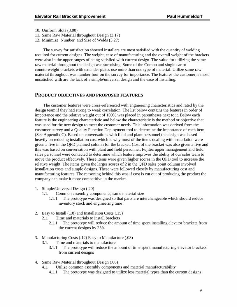
Figure 7 Concept #3 Extension Tube The three concepts were evaluated using a weighted decision matrix on a five-point scale, four being excellent and zero being inadequate. The criteria that each concept was evaluated against were the engineering design characteristics from the project objectives. The project objectives had a weight factor calculated based on customer feedback. The score given in each category was multiplied by the weight factor to determine the rating for each concept. The ratings for all design concepts were summed to determine the overall rating for each concept (see Appendix G). The concept with the highest rating was concept #2 extension angles (see Table 1). This concept then became the focus of this design project and all calculations and testing was conduced to prove the design was feasible (see Figure 8 on following page).
Table 1 Weighted Objective Matrix Results
Weighted Objective Matrix Results
Angles with Plate 1.94
All Angles 3.31
Angles with Tube 2.95
Elevator Rail Bracket Improvement Paul Hummeldorf
10
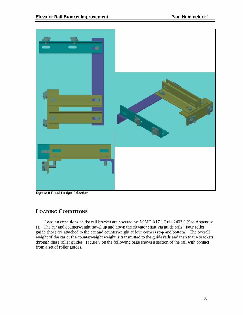
Figure 8 Final Design Selection LOADING CONDITIONS Loading conditions on the rail bracket are covered by ASME A17.1 Rule 2403.9 (See Appendix H). The car and counterweight travel up and down the elevator shaft via guide rails. Four roller guide shoes are attached to the car and counterweight at four corners (top and bottom). The overall weight of the car or the counterweight weight is transmitted to the guide rails and then to the brackets through these roller guides. Figure 9 on the following page shows a section of the rail with contact from a set of roller guides.

Elevator Rail Bracket Improvement Paul Hummeldorf
11
Figure 9 Car or Counterweight Roller Guide Configuration The car weights used for this design project are for a standard 3500 lb Talon platform with nine foot entrance height. From job to job this car frame weight will remain constant. The factor that has the greatest effect on the weight is the car interior options. These are the aesthetic items the riders would see using the elevator. For this project the interior options were assumed to be the heaviest available to simulate worst case (i.e. stone floors, glass wall panels, drop ceiling, etc.). When the total car weight (car frame and cab w/interiors) was calculated, this weight along with the capacity of car (3,500 lbs) was used to calculate the seismic load. ASME A17.1 calculates seismic load using 100% of the car weight and 40% of the rated capacity for the car and the total weight of the counterweight for loading. The next step in determining the rail loading was to determine roller guide spacing on car and counterweight in relation to the rail bracket spacing in the building. If the rail bracket spacing is greater than the roller guide spacing on the car and counterweight a more stringent ASME A17.1 formula is utilized. For this project the assumption was made that the roller guide spacing is less than the bracket spacing, this would simulate worst case conditions. In addition, if the elevator is installed in a seismic region more of the calculated load is used in the formulas to find rail forces. For this project all seismic formulas were used to again simulate worst case conditions.

Elevator Rail Bracket Improvement Paul Hummeldorf
12
Loads for this project calculated utilizing worst case car and counterweight weights per ASME A17.1 standards can be seen in Figure 10.
Figure 10 Seismic Loading Conditions

Elevator Rail Bracket Improvement Paul Hummeldorf
13
DESIGN CALCULATIONS The rail bracket was analyzed with a distance of 20 inches from mounting surface to the back of the guide rail for the car, and 16 ¾ inches from the mounting surface to the center of the counterweight rail for counterweight. Utilizing these spans the analysis applies for brackets with a shorter span and no further calculations will be required. The design was analyzed for stresses and deflection utilizing MathCAD software (see Appendix I). Using the calculated seismic loads from the last section, the calculations were done in three parts (see Figure 11).
Figure 11 Sections of Design Analysis Part one is the analysis of the car side of the bracket. Part one is broken into three sections, two on welding stress and the third on bending stress in the extension angles. The first welded joint closest to the car rail was analyzed for maximum shear stress. This was accomplished using the following equations for primary and secondary shear [3]. Primary Shear
τ P1 2198 psi=
Secondary Shear
τ S1 2481 psi= The maximum shear was calculated using vector resolution to find shear in ‘x’ and ‘y’ components. These values were then used in the following equation to find maximum shear stress. Maximum Shear Stress
τ 4644 psi=

Elevator Rail Bracket Improvement Paul Hummeldorf
14
This value was used to determine factor of safety based on allowable per AWS D1.1-2004 Table 2.3 [4]. The allowable shear stress per AWS is 40% times the yield strength of the base material or 30% times the tensile strength of filler material. The base material used for this project is A36 steel which Fyp
Base Material
FS 3.1=
(Yield Strength) = 36,000 psi. The filler material used is an E60 electrode which has a tensile strength of 60,000 psi. Using these values with the maximum shear stress above the factors of safeties were determined.
Filler Material
FS 3.9= The second welded area (the one sitting on the shared shelf angle) in part one was analyzed using the same method. The calculated values are as follows.
The final calculation for part one of the car rail was to find the bending stress in the extension angles. This was accomplished by finding bending force due to ‘x’ and ‘y’ forces applied to the rail. The bending moment in the ‘y’ direction was found by the force times the perpendicular distance. Bending Moment created by Force in the "Y" Direction
M Py 28148 in lbf.= This moment was then used to find bending stress using the moment of inertia of the angles group and the centroid.
σ Py 2150 psi=
Bending Stress in the “Y” Direction
Factors of safety for bending in elevator rail brackets are governed by ASME A17.1 1996 Table 2403.7. This table states that the allowable bending stress is 88% times the yield strength of the base material. In this case that is 36,000 psi. The extension angles the factor of safety was calculated.
Maximum Shear Stress
Primary Shear
τ P2 1758 psi=
Secondary Shear
τ S2 8577 psi=
τ 10268 psi=
FS 1.4=
Base Material
FS 1.8=
Filler Material

Elevator Rail Bracket Improvement Paul Hummeldorf
15
F.S. =0.88 F yp.
σ Py14.734=
Bending Stress Factor of Safety in the “Y” Direction
Deflection (Δ) of the extension angles in the “Y” direction was calculated. The maximum deflection allowed per ASME A17.1 1996 Table 2403.7 in rail brackets is 0.10 inches.
∆ max 0.001 ft in= <-- Per ASME A17.1-1996 Table 2403.7:
Allowable Deflection = 0.10in
Deflection in the “Y” Direction
Bending stress and deflection due to forces in the ‘x’ direction were analyzed in a similar manner and the calculated values are as follows. Bending Moment created by Force in the "X" Direction
M Px 9035 in lbf.=
σ Px 9139 psi=
Bending Stress in the “X” Direction
F.S. =0.88 F yp.
σ Px3.5=
Bending Stress Factor of Safety in the “X” Direction
∆ max 0.000306in= <-- Per ASME A17.1-1996 Table 2403.7:
Allowable Deflection = 0.10in
Deflection in the “X” Direction

Elevator Rail Bracket Improvement Paul Hummeldorf
16
Part two of the calculations involved analysis of the counterweight rail support angle. The methodology to find weld and bending stresses was similar to those used on the car side bracket. Calculated values for weld stress are as follows. Primary Shear
τ P1 1450 psi=
Secondary Shear
τ S1 13703 psi= Maximum Shear Stress
τ 14846 psi= Base Material
FS 1=
Filler Material
FS 1.2= The calculated values for bending and deflection in the counterweight angle are as follows. Bending Moment created by Force in the "Y" Direction
M Py 7110 in lbf.=
σ 3592 psi=
Bending Stress in the “Y” Direction
F.S. =0.88 F yp.
σ8.8=
Bending Stress Factor of Safety in the “Y” Direction
∆ max 0.001 in=
Deflection in the “Y” Direction
Bending Moment created by Force in the "X" Direction
M Px 47300 in lbf.=
σ 23893 psi=
Bending Stress in the “X” Direction
F.S. =0.88 F yp.
σ1.3=
Bending Stress Factor of Safety in the “X” Direction
∆ max 0.057 in=
Deflection in the “X” Direction

Elevator Rail Bracket Improvement Paul Hummeldorf
17
The final part of the rail bracket analysis involved finding the stresses in the shared shelf angle. This part was the most difficult due to the combined loading conditions (car and counterweight). The shelf angle is either attached to the building support via welds or bolts into embedded inserts. In the case of welding the shelf angle to the building steel, the basic steps are the same as the other welds except when finding moments in the x and y direction, combined loading is utilized. The moments were summed about the centroid of the weld group. Moment of inertia in the x and y direction was calculated using formulas from the text solutions to design of weldments [5] for this particular weld pattern. These inertias were then used to calculate the maximum stress.
τ Px 1649 psi= τ Py 12534 psi=
τ τ Px2
τ Py2
τ 12642 psi=
Maximum Stress (Normal and Shear)
To determine the factor of safety the same equations were utilized from the previous weld calculations. Base Material
FS 1.1=
Filler Material
FS 1.4= In the second case using two 5/8” bolts to attach the bracket to the support structure was broken into two cases. In the first case the car and counterweight loads assume to act in the same direction (worse case) placing a shear force on the bolts. This shear stress was then calculated.
τ b 10686 psi=
For (2) Bolts, Shear Stress
An AISC guideline for A307, grade 2 bolts is that max shear equates to 40% the ultimate strength of the material. For A307 grade 2 bolts the ultimate strength is 60,000 psi. Factor of safety is then calculated.
FS 2.2=
Bolts Shear Stress Factor of Safety
This case will also impose a moment force on the bolts which will cause the bolts to have a tension reaction on them. To find the tensile stress the forces were summed about a point furthest away from the bolts and forces. This equation was then arranged to equal one of the two unknowns (the two bolt locations). Utilizing the lever rule
Ra 1da 1
Ra 2da 2
Ra 1Ra 2da 2
da 1.=>
Lever Rule

Elevator Rail Bracket Improvement Paul Hummeldorf
18
The equation derived from summing the moments was plugged into the equation from the lever rule. This enabled one of the unknowns to be solved. This solution was then used to solve for the second unknown. The tension in each of the bolts was calculated.
Ra 1 962 lbf=
Tension in Bolts
Ra 2 4877 lbf= Max tensile strength was then determined with the bolt seeing the greatest load and calculated.
σ aRa 2A b
σ a 21581 psi=
Maximum Tensile Stress
Per AISC for bolts in tension max allowable is 75% ultimate strength of the material [6].
x F S2=
Bolts Tension Factor of Safety
The second and final case for bolts in tension involved only the counterweight force push in towards the mounting surface. Since the load point was offset from the bolts a moment was created imposing tension on the insert bolts. This tensile stress was calculated in a similar manner as the first case. A reaction force at the bolt was calculated summing the moments. This reaction force was then used to find max tensile stress.
σ bRbA b
σ b 12301 psi=
Maximum Tensile Stress
Factor of safety was solved the same as the first case.
x F S3=
Bolts Tension Factor of Safety
All factors of safety calculated for the improved rail bracket design were one or greater meaning they meet all core requirements for design. If a rail bracket is designed with a mounting surface at or less than 20” for car and 16 ¾” for counterweight it will meet all code requirements. If the bracket is designed for greater distances, more analysis will have to be conducted to ensure code compliant. All raw material used on the improved bracket design is the same type. Approximately six feet of 3”x3”x3/8” angle iron is needed for the bracket used in the calculations. Other than the angle only four rail clips (device used to hold the guide rail to the rail bracket) and some miscellaneous 5/8” nuts and bolts will be used to assemble the angles.

Elevator Rail Bracket Improvement Paul Hummeldorf
19
FABRICATION AND ASSEMBLY Manufacturing detail drawings for both types of combination brackets were generated from 3D Cad files. The drawings for the improved bracket can be seen in Appendix J. The bracket with the plate was fabricated using a plasma torch cutting table (Figure 12) and a beam worker (Figure 13). The improved design required only the beam worker for manufacturing. Both brackets were assembled with 5/8” nuts and bolts and then preceded to testing.
Figure 12 Plasma Torch Cutting Table
Figure 13 Beam Worker

Elevator Rail Bracket Improvement Paul Hummeldorf
20
TESTING MANUFACTURING Set-up and machine times were documented for each style bracket. Set-up time for both machines was approximately twenty minutes. The biggest difference between the two designs is the improved design is manufactured out of all the same material. The savings between the plasma cutting table and the beam worker resulted in a savings of a minute per bracket. Every elevator manufactured by Fujitec requires rail brackets. This relatively small time savings should reap large savings over time. The improved design utilized lighter material than the old or current design. This lighter material meant a reduction in the overall bracket weight of five pounds. The cost to purchase the raw material also was reduced by approximately $2.50. INSTALLATION Both brackets were tested for installation utilizing a mock-up rig (Figure 14). Each bracket was simulated being installed five times (See Table 2). Times to install each design averaged the same time. The welding lengths and sizes used for each bracket was the same.
Figure 14 Bracket Mock-Up Table 2 Installation Times Old vs. New Old or Currrent Design (plate) Improved Design (angles)
Run Time (min.) Run Time (min)1 23 1 302 25 2 243 22 3 214 25 4 235 24 5 21
Average 23.80 Average 23.80

Elevator Rail Bracket Improvement Paul Hummeldorf
21
CONCLUSION AND RECOMMENDATIONS The improved bracket design met all requirements for manufacturing. The installation side proved to be no longer than current designs. Manufacturing the improved bracket proved to be the greatest cost savings. The list below summarizes the savings in manufacturing.
• Saved 11% on the overall cost for the raw material $2,330.50 / year *
• Reduced manufacturing time by 55 seconds per bracket $1,300.00 / year *
• Reduced machine setup time by 50% $4,000.00 / year *
• Reduced the overall weight of the bracket by five pounds * Figures based on installing ten stop Talons (100/year projected sales for the next five years) All product objectives were exceeded less the overall cost to install. The initial plan was to reduce the install time by 25%. The overall time did not increase so the new bracket design didn’t negatively affect the total cost currently. Some recommendations would be to assemble a team of elevator installers that can troubleshoot the improved design with the goal of reducing the total installation time. Additional calculations could be completed to reduce the current weld lengths which would reduce installation time. The final recommendation is to present to Fujitec management to utilize the design concepts in the improved design for traditional overhead elevator applications. SCHEDULE AND BUDGET A project schedule was created to ensure project completion was accomplished in the allotted time. The schedule is formatted in Gantt style (See Appendix E). The project timeline covers three quarters of the school year and ends 6/9/07. All scheduled dates were met and no changes had to be made to the schedule. Here is a list of some of the keys dates in the project schedule.
• 1/14/07 Proof of design and design agreement with project advisor • 2/25/07 Design freeze. (end of designing) • 3/11/07 Design report due • 3/12/07 Oral presentation of the design • 5/6/07 Demonstration of the prototype (full size mock-up) • 5/16/07 Tech Expo • 5/30/07 Oral presentations • 6/4/07 Final project report due
A budget was created to ensure overall costs are covered and are in the acceptable range of project scope (See Appendix F). Most of the cost of the project was covered by Fujitec America, Inc. The actual design time needed was split between work and independent locations. The vast majority of the cost was the welding tests of the brackets building the mock-up. The total amount needed for
Elevator Rail Bracket Improvement Paul Hummeldorf
22
the project is projected was initially estimated to be $415.00. The actual cost of the entire project was $500.00. This overage was within 25% of the estimated budget and within an acceptable range for Fujitec management.

Elevator Rail Bracket Improvement Paul Hummeldorf
23
REFERENCES 1 ASME A17.1-1996, Safety Code for Elevators and Escalators, The American Society of Mechanical Engineers, 1996 2 Hollister-Whitney Elevator Corp., [Online product Catalog] 09/26/06 http://www.hollisterwhitney.com/products/accessories.html 3 Joseph Edward Shigley, Mechanical Engineering Design. New York: McGraw-Hill,1989. 4 AWS D1.1/D1.1M:2004, Structural Welding Code-Steel, American Welding Society, 2004 5 James F. Lincoln Arc Welding Foundation, Solutions to the Design of Weldments D810.17, The Lincoln Electric Company. 6 AISC 2005, Steel Construction Manual, American Institute of Steel Construction, 2005

Appendix A1
APPENDIX A CURRENT RAIL BRACKET DESIGNS
9/27/06 Traditional Combo Rail Bracket, Fujitec America Inc.
• Good application for traditional applications.
• Different material types and sizes used. • Extensive welding required. Used on traditional elevator configuration with counter located on side of car. Counterweight is offset the car guide rail.

Appendix A2
9/27/06 U-Type Combo Rail Bracket, Fujitec America Inc.
• Applied to traditional elevator configuration when counterweight is centered on the car rail.
• Installation can be time consuming • Can utilize the same material type. Used on traditional elevator configuration with counter located on side of car. Counterweight is centered on the car guide rail.

Appendix A3
9/27/06 Divider Rail Bracket, Fujitec America Inc.
• Applied to traditional elevator configuration when cars are grouped.
• Installation is simple.
Used on elevator configuration with cars side by side sharing hoist ways
Appendix A4
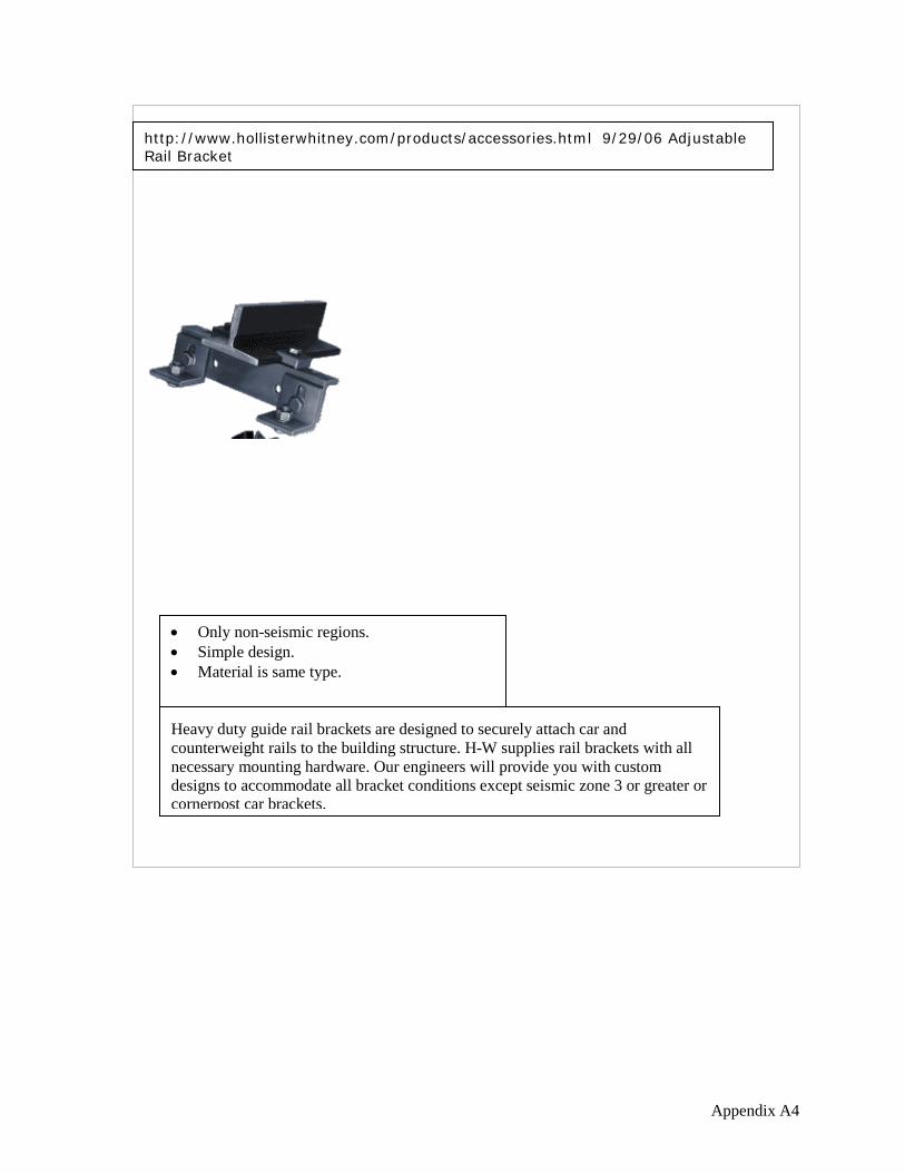
http://www.hollisterwhitney.com/products/accessories.html 9/29/06 Adjustable Rail Bracket
• Only non-seismic regions. • Simple design. • Material is same type.
Heavy duty guide rail brackets are designed to securely attach car and counterweight rails to the building structure. H-W supplies rail brackets with all necessary mounting hardware. Our engineers will provide you with custom designs to accommodate all bracket conditions except seismic zone 3 or greater or cornerpost car brackets.

Appendix A5
9/27/06 Angle-Plate-Angle Car Rail Bracket, Fujitec America Inc.
• Applied to elevator car rail. • Applies to only one rail. • Different material type. • Can be used on counterweight rail in some
instances. Used on elevator car rails with counterweight located towards the rear of the car.

Appendix A6
9/27/06 Angle-Angle Rail Bracket, Fujitec America Inc.
• Applied to elevator car or counterweight rail. • Can utilize the same material type. • Only applies to one rail
Used on elevator car or counterweight guide rail.

Appendix A7
9/27/06 Angle-Angle Counterweight Rail Bracket, Fujitec America Inc.
• Applied to elevator counterweight rail. • Can utilize the same material type. • Only applies to one rail. • Simple.
Used on elevator counterweight guide rail when not grouped with car rail

Appendix A8
9/27/06 Flat bar Counterweight Rail Bracket, Fujitec America Inc.
• Applied to elevator counterweight rail. • Only one material type. • Only applies to one rail. • Simple. • Little to no adjustment
Used on elevator counterweight guide rail when not grouped with car rail.

Appendix B1
APPENDIX B DESIGN SURVEY

Appendix C1
APPENDIX C QUALITY FUNCTION DEPLOYMENT
9 = Strong3 = Moderate1 = Weakno relation = blank
com
pone
nt c
ost
com
mon
ass
embl
y co
mpo
nent
s
com
pone
nt w
eigh
t
mat
eria
l man
ufac
tura
bilit
y
layo
ut g
eom
etry
com
pone
nt fi
nish
com
pone
nt e
ase
to in
stal
l
com
pone
nt e
ase
to m
anuf
actu
re
Cus
tom
er im
porta
nce
Satis
fact
on
Plan
ned
brac
ket d
esig
n
Impr
ovem
ent r
atio
Sale
s po
ints
Impr
ovem
ent (
Abso
lute
wei
ght)
ratio
Rel
ativ
e w
eigh
t
Installation1. Minimize welding 1 1 9 4.1 3.27 4 1.2 1.0 5.0 0.042. Simple/ Universal Design 3 9 1 9 3 4.5 2 5 2.5 2.0 22.5 0.203. Light assembly 3 9 3 4.1 3 3 1.0 1.0 4.1 0.044. Temporary attachment 3 1 3.2 2.6 2 0.8 1.0 2.5 0.025. Easy to install 9 9 4.8 2.33 5 2.1 2.0 20.47 0.18Manufacturing6. Same raw material size 3 3 3 3 4.8 3.17 4 1.3 1.5 9.1 0.087. Uniform slots 3 3 1 9 4.4 3 4 1.3 1.5 8.9 0.088. Easy to manufacture 3 9 3 9 4.5 3 4 1.3 1.5 8.9 0.08Aesthetics9. Bracket Color 9 1.0 1.5 1 0.7 1.0 0.6 0.0110. No visible unused slots 1 1 3.1 2.67 1 0.4 1.0 1.2 0.01Cost11. Installation cost 3 9 4.9 2.83 5 1.8 2.0 17.42 0.1512. Manufacturing cost 3 3 9 4.9 2.67 5 1.9 1.5 13.76 0.12
Absolute Importance 1.8
2.01
2.43
1.37
0.79
0.05
5.28
3.31 114.5 1.00
Relative importance 0.10
0.12
0.14
0.08
0.05
0.00
0.31
0.19
Direction of movement Dow
n
Up X X X X
Dow
n
Dow
n
Units $ lbs.
Sec
$
17.01

Appendix D1
APPENDIX D PRODUCT OBJECTIVES Reduce the amount of Welding
Just enough to meet ASME A17.1
The prototype was designed with enough welds to meet code requirements but no more than required.
Simple/Universal Design
Common assembly components
The prototype was designed so that some parts are interchangeable which should reduce inventory stock and engineering time.
Lightweight Assembly
Weight The prototype will weight not more than current designs
Temporary Attachment
Layout Geometry The prototype will have capability of being temporarily attached to building steel prior to welding to aid in adjustment phase.
Easy to Install Time Taken to Install The prototype will reduce the amount of time spent installing elevator brackets from the current designs.
Same Raw Material Size
Common assembly components and material manufacturability
The prototype was designed to utilize less material types than current designs.
Uniform Slots Standard Tooling on same datum.
The prototype will use standard tooling dies and have fewer variations of slots than current designs.
Easy to Manufacture
Time to Manufacture The prototype will reduce the amount of time spent manufacturing elevator brackets from current designs.
Bracket Color Finish by code The prototype will have the minimum finish required to meet code or specifications.
No Visible Unused Slots
Layout of slots The prototype will have the minimum slots required to achieve objective.
Installation Costs Time and Material to Install
The prototype will reduce the amount of time spent installing elevator brackets from current designs.
Manufacturing Costs
Time and Material to Manufacture
The prototype will reduce the amount of time spent manufacturing elevator brackets from current designs.

Appendix E1
APPENDIX E SCHEDULE Hummeldorf, Paul Elevator Rail Bracket Improvement
Spring Break
Dates 1/1-
1/7
1/8-
1/14
1/15
-1/2
1
1/22
-1/2
8
1/29
-2/4
2/5-
2/11
2/12
-2/1
8
2/19
-2/2
5
2/26
-3/4
3/5-
3/11
3/12
-3/1
8
3/19
-3/2
5
3/26
-4/1
4/2-
4/8
4/9-
4/15
4/16
-4/2
2
4/23
-4/2
9
4/30
-5/6
5/7-
5/13
5/14
-5/2
0
5/21
-5/2
7
5/28
-6/3
6/4-
6/10
Tasks(Deadlines)
Proof of design/Agreement (1/14/07)
Weighted Objective Method
Design of Bracket
FEA anaylisis
Excel Sheet for sizing Bracket
ASME A.17 Code Check
Design of Manufacturing
Design Freeze (2/25/07)
Order Parts
Oral Design Presentation (3/12/07)
Touch up design
Design Report (3/11/07)
Spring Break
Build Bracket
Build mock-up building support
Install Bracket on Mock-up or Test Tower
Demonstration (5/6/07)
Correct problems
Tech EXPO (5/16/07)
Start Oral Presentation (5/30/07)
Project Report (6/4/07)
Winter Quarter Spring Quarter
(1/14/07)
(2/25/07)
(3/12/07)
(5/06/07)
(5/16/07)
(5/30/07)(6/04/07)
(3/11/07)

Appendix F1
APPENDIX F BUDGET Hummeldorf, Paul Elevator Rail Bracket Project
BudgetMaterials,Components or Labor Forcasted Amount Actual Amount
Bracket $75.00 $85.00Hardware and clips $20.00 $20.00Machine time (two hours) $160.00 $195.00Welding booth (two hours) $160.00 $200.00Total $415.00 $500.00

Appendix G1
APPENDIX G WEIGHTED DECISION MATRIX
Weighted Decision Matrix for Elevator Rail Bracket Improvement
Design CriterionWeight Factor Magnitude Score Rating Magnitude Score Rating Magnitude Score Rating
Component Cost 0.10 Satisfactory 2 0.20 Good 3 0.30 Weak 1 0.10Common assembly Components 0.12 Weak 1 0.12 Excellent 4 0.48 Good 3 0.36
Component Weight 0.14 Satisfactory 2 0.28 Good 3 0.42 Excellent 4 0.56Material Manufactureability 0.08 Good 3 0.24 Excellent 4 0.32 Satisfactory 2 0.16
Layout Geometry 0.05 Satisfactory 2 0.10 Satisfactory 2 0.10 Good 3 0.15Component Finish 0.00 Satisfactory 2 0.00 Satisfactory 2 0.00 Satisfactory 2 0.00
Component Easy to install 0.31 Satisfactory 2 0.62 Good 3 0.93 Excellent 4 1.24Component Easy to Manufacture 0.19 Satisfactory 2 0.38 Excellent 4 0.76 Satisfactory 2 0.38
1.94 3.31 2.95
Excellent 4Good 3
Satisfactory 2Weak 1
Inadequate 0
Angles with Extension Plate All Angles Angles with Large Tube
Appendix H1
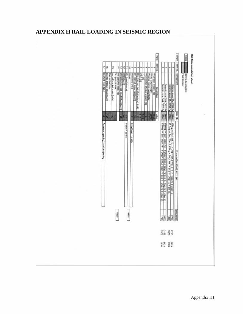
APPENDIX H RAIL LOADING IN SEISMIC REGION

Appendix H2

Appendix H3

Appendix I1
APPENDIX I RAIL BRACKET CALCULATIONS

Appendix I2

Appendix I3

Appendix I4

Appendix I5

Appendix I6

Appendix I7

Appendix I8

Appendix I9

Appendix I10

Appendix I11

Appendix I12

Appendix I13

Appendix I14

Appendix I15

Appendix I16

Appendix I17

Appendix J1
APPENDIX J RAIL BRACKET MANFACTURING DRAWINGS

Appendix J2

Appendix J3

Appendix J4

Appendix J5