elevator controller manual - rst elektronik gmbh
TRANSCRIPT

9.620.123-6.docx Page 1 of 123
Elevator Controller
Manual
IMC-2

9.620.123-6.docx Page 2 of 123
Issued by: RST Elektronik GmbH Tannenstraße 11 74229 Oedheim Phone: +49 7136 / 9912-0 Fax: +49 7136 / 9912-10 www.rst-elektronik.de Copyright: © 2017 RST Elektronik GmbH
All rights reserved by the publisher, including reprinting and copying of extracts of the present manual. No part of this manual shall be reproduced or copied using electronic reproduction systems in any way, unless the publisher approved of such reproduction or copying in writing before.
RST Document No.: 9.620.123-6.docx Valid as from software: 19.172.083 Subject to change
Contents
9.620.123-6.docx Page 3 of 123
Contents
1 General ..................................................................................................................... 8
1.1 Information about this manual .........................................................................................................8
1.2 Co-applicable documents ................................................................................................................8
1.3 Signs and symbols ..........................................................................................................................9
2 General safety regulations .................................................................................... 10
2.1 Requirements to be met by the assembly personnel ................................................................... 10
2.2 Hazards ........................................................................................................................................ 10
2.3 Safety regulations......................................................................................................................... 11
2.4 Service / Disposal......................................................................................................................... 12
3 Modules .................................................................................................................. 13
3.1 Main board ................................................................................................................................... 13
3.1.1 General ................................................................................................................................. 14
3.1.2 Technical Data ...................................................................................................................... 14
3.1.3 Jumper .................................................................................................................................. 14
3.1.4 Special LEDs......................................................................................................................... 14
3.1.5 Operating elements ............................................................................................................... 15
3.1.6 List of terminals ..................................................................................................................... 15
3.2 Cabin control module (KSM) ........................................................................................................ 19
3.2.1 General ................................................................................................................................. 19
3.2.2 Technical Data ...................................................................................................................... 19
3.2.3 Jumper / rotary encoder switch ............................................................................................. 20
3.2.4 Special LEDs......................................................................................................................... 20
3.2.5 Location of terminals / Layout ............................................................................................... 21
3.2.6 List of terminals ..................................................................................................................... 22
3.2.7 Safety information referring wiring of the KSM .................................................................... 27
3.3 Universal Bus Module (UBM) ....................................................................................................... 28
3.3.1 General ................................................................................................................................. 28
3.3.2 Technical Data ...................................................................................................................... 28
3.3.3 Jumper / rotary encoder switch ............................................................................................. 28
3.3.4 Special LEDs......................................................................................................................... 29
3.3.5 Location of terminals / Layout ............................................................................................... 29
3.3.6 List of terminals ..................................................................................................................... 29
3.4 Port Expander Module (PEM) ...................................................................................................... 30
3.4.1 General ................................................................................................................................. 30
3.4.2 Technical Data ...................................................................................................................... 30
3.4.3 Jumper .................................................................................................................................. 30
3.4.4 Location of terminals / Layout ............................................................................................... 31

Contents
9.620.123-6.docx Page 4 of 123
3.4.5 List of terminals ..................................................................................................................... 31
3.5 Car position indicator module (EAM) ........................................................................................... 32
3.5.1 General ................................................................................................................................. 32
3.5.2 Technical Data ...................................................................................................................... 32
3.5.3 Jumper / rotary encoder switch ............................................................................................. 32
3.5.4 Special LEDs......................................................................................................................... 32
3.5.5 Location of terminals / Layout ............................................................................................... 33
3.5.6 List of terminals ..................................................................................................................... 33
3.6 Car operation panel (ITM) ............................................................................................................ 34
3.6.1 General ................................................................................................................................. 34
3.6.2 Technical Data ...................................................................................................................... 34
3.6.3 Rotary encoder switch .......................................................................................................... 34
3.6.4 Special LEDs......................................................................................................................... 35
3.6.5 Location of terminals / Layout ............................................................................................... 35
3.6.6 List of terminals ..................................................................................................................... 36
3.7 Bluetooth module (BTM) .............................................................................................................. 39
3.7.1 General ................................................................................................................................. 39
3.7.2 Technical Data ...................................................................................................................... 39
3.7.3 Jumper / rotary encoder switch ............................................................................................. 39
3.7.4 Special LEDs......................................................................................................................... 39
3.8 Hand-held terminal ....................................................................................................................... 40
3.8.1 General ................................................................................................................................. 40
3.8.2 Technical Data ...................................................................................................................... 40
3.9 Safety monitoring module ............................................................................................................ 41
3.9.1 General ................................................................................................................................. 41
3.9.2 Technical Data ...................................................................................................................... 41
3.9.3 Location of terminals / Layout ............................................................................................... 42
3.9.4 List of terminals ..................................................................................................................... 42
3.9.5 Test ....................................................................................................................................... 43
3.9.6 Activation in controller ........................................................................................................... 43
3.10 CAN bus ....................................................................................................................................... 44
3.10.1 General ................................................................................................................................. 44
3.10.2 Technical Data ...................................................................................................................... 44
3.10.3 Setting the node IDs ............................................................................................................. 44
3.11 Travelling cable ........................................................................................................................... 45
3.11.1 General ................................................................................................................................. 45
3.11.2 Technical Data ...................................................................................................................... 45
3.11.3 Wire allocation ...................................................................................................................... 46
4 Menu and operation ............................................................................................... 47
4.1 General ......................................................................................................................................... 47
4.2 Start screen .................................................................................................................................. 47
4.3 Entering parameter values ........................................................................................................... 48
Contents
9.620.123-6.docx Page 5 of 123
4.4 Selection lists ............................................................................................................................... 48
4.5 General menu structure ............................................................................................................... 49
4.6 Setup menu .................................................................................................................................. 56
4.6.1 Plant ...................................................................................................................................... 56
4.6.2 Drive ...................................................................................................................................... 57
4.6.3 Position Reference ................................................................................................................ 58
4.6.4 Doors ..................................................................................................................................... 60
4.6.5 Controller ............................................................................................................................... 63
4.6.6 Monitorings............................................................................................................................ 68
4.6.7 Energy Save (ECO) .............................................................................................................. 70
4.6.8 Anti Nuisance ........................................................................................................................ 71
4.6.9 Inverter settings .................................................................................................................... 71
4.6.10 Group .................................................................................................................................... 72
4.7 Display/Diagnostic ........................................................................................................................ 73
4.7.1 Error Log ............................................................................................................................... 73
4.7.2 CAN Bus ............................................................................................................................... 73
4.7.3 Inputs/outputs ....................................................................................................................... 74
4.7.4 Actual Values ........................................................................................................................ 75
4.7.5 Statistics ................................................................................................................................ 76
4.7.6 Actual Calls ........................................................................................................................... 76
4.7.7 Software version ................................................................................................................... 76
4.7.8 Remote Access ..................................................................................................................... 76
4.8 System ......................................................................................................................................... 77
4.8.1 Inverter Control ..................................................................................................................... 77
4.8.2 Language .............................................................................................................................. 77
4.8.3 Time/Date .............................................................................................................................. 77
4.8.4 Set Time/Date ....................................................................................................................... 77
4.8.5 Code ...................................................................................................................................... 78
4.8.6 Menu Access......................................................................................................................... 78
4.8.7 USB Host .............................................................................................................................. 78
4.8.8 Uploading software-Updates via integrated Flash Loader .................................................... 79
4.9 Service ......................................................................................................................................... 80
4.9.1 Calls ...................................................................................................................................... 80
4.9.2 Assembly mode .................................................................................................................... 81
4.9.3 Display services .................................................................................................................... 81
4.9.4 TÜV / Test ............................................................................................................................. 82
4.9.5 Calibration of Inverter ............................................................................................................ 82
4.9.6 Service Interval ..................................................................................................................... 83
4.9.7 Erase Rel. Counter ............................................................................................................... 83
4.9.8 Monitoring ............................................................................................................................. 83
4.10 Programmable I/0 functions ......................................................................................................... 84
4.10.1 General ................................................................................................................................. 84
4.10.2 Programming......................................................................................................................... 84
5 Position reference systems .................................................................................. 85

Contents
9.620.123-6.docx Page 6 of 123
5.1 SSI absolute encoder ................................................................................................................... 85
5.2 ELGO LIMAX with SSI interface .................................................................................................. 85
5.3 Shaft incremental encoder 1024 Pulses HTL +15.. +24V ............................................................ 85
5.4 Motor incremental encoder 1024 Pulses HTL +15.. +24V ........................................................... 85
6 Learn Run ............................................................................................................... 86
6.1 General ......................................................................................................................................... 86
6.2 Execution ...................................................................................................................................... 86
7 Setting the flush positions .................................................................................... 88
7.1 Flush correction via hand-held terminal or IMC-2 main board ..................................................... 88
7.2 Correction at cabin control panel ................................................................................................. 89
8 Bypass-Operation .................................................................................................. 90
8.1 General Information ..................................................................................................................... 90
8.2 Functional description .................................................................................................................. 90
9 Inspection controller ............................................................................................. 91
9.1 General Information ..................................................................................................................... 91
9.2 Functionality ................................................................................................................................. 91
10 UCM Detection (unwanted cabin movement) ...................................................... 92
10.1 General ......................................................................................................................................... 92
10.2 Description of function .................................................................................................................. 92
10.3 Test .............................................................................................................................................. 93
10.3.1 Preparations .......................................................................................................................... 93
10.3.2 Execution .............................................................................................................................. 93
10.3.3 Check of requirements as per EN81-A3 ............................................................................... 93
10.3.4 Re-commissioning the plant .................................................................................................. 93
10.3.5 Regular testing ...................................................................................................................... 93
11 Self-monitoring of UCM safety gear per EN81-20 ............................................... 94
11.1 Field of application ....................................................................................................................... 94
11.2 Monitoring inputs at IMC-2 controller ........................................................................................... 94
11.3 Parameterization .......................................................................................................................... 94
11.3.1 Activation of monitoring function per EN81-20 ..................................................................... 94
11.3.2 Determination of signal level (High active or Low active) ..................................................... 94
11.3.3 Determination of wait time until check of feedback contacts ................................................ 95

Contents
9.620.123-6.docx Page 7 of 123
11.4 Overview of monitored states and error messages ..................................................................... 95
11.5 Resetting errors ............................................................................................................................ 95
11.6 Functional test during on-site commissioning .............................................................................. 96
12 CANDrive interface ................................................................................................ 97
12.1 General ......................................................................................................................................... 97
12.2 Operating modes .......................................................................................................................... 97
12.2.1 CANDriveVelocity ................................................................................................................. 97
12.2.2 CANDrivePosition ................................................................................................................. 97
12.3 Procedure ..................................................................................................................................... 97
12.3.1 Activation ............................................................................................................................... 97
12.3.2 Calibration in CANDrivePosition mode ................................................................................. 98
12.3.3 Special features in CANDrivePosition mode ........................................................................ 98
13 LiftControl for plant setup / diagnoses via PC .................................................... 99
13.1 General ......................................................................................................................................... 99
13.2 Important features ........................................................................................................................ 99
14 Remote monitoring via Monitoring System ....................................................... 100
15 Group mode ......................................................................................................... 101
15.1 General ....................................................................................................................................... 101
15.2 Description of system ................................................................................................................. 101
15.3 Group of 2 - Schematic circuit diagram ...................................................................................... 102
16 Certifications ........................................................................................................ 103
17 List of errors ......................................................................................................... 116
18 Index ..................................................................................................................... 123

General Information about this manual
9.620.123-6.docx Page 8 of 123
1 General
1.1 Information about this manual
This assembly manual describes a recommended assembly method which has been implemented successfully many times. However, RST Elektronik does not guarantee that this assembly variant can also be applied to other lift plants. The Customer alone shall be responsible for complying with the local regulations and adjusting the special circuitry features of each lift installation to the relevant technical requirements. RST Elektronik shall not be held responsible for any loss and/or damage resulting from the Customer's negligence during the execution of the assembly. This shall apply in particular to any non-compliance with the Assembly and Commissioning Instructions/Manuals supplied with our products. Before starting the work, read these instructions carefully. Compliance with all safety instructions contained in this manual is a prerequisite for safe working. In addition to this manual, the applicable local accident prevention and safety regulations must be complied with.
1.2 Co-applicable documents In addition to this manual, the following documents shall also be complied with: “IMC-2 Assembly and Commissioning Instructions” (RST-document 9.627.xx)

General Signs and symbols
9.620.123-6.docx Page 9 of 123
1.3 Signs and symbols
Dangerous electric voltage
General hazard area Activities where various causes might result in personal damage. Suspended load Activities involving the risk of being injured by loads falling down. Danger of falling Activities involving the risk of falling down.
Crushing hazard General information

General safety regulations Requirements to be met by the assembly personnel
9.620.123-6.docx Page 10 of 123
2 General safety regulations This chapter summarizes all important safety regulations and instructions. These safety regulations must always be followed when working on the plant.
Anybody carrying out assembly and commissioning work on the IMC-2 controller must read this chapter and implement its instructions in practice.
2.1 Requirements to be met by the assembly personnel
Assembly personnel must: be 18 years of age (exception: trainees (min. 16 years of age) who are permanently
supervised by a qualified trainer). be capable of providing first aid, know and implement the fire protection and explosion protection directives applying to the
relevant work area, know, avoid/prevent and take action against all hazards involved in the work in the shaft
and the equipment rooms, be able to identify and repair all irregularities and faults during assembly and operation of a
lift plant, know and apply the technical basics of the function and operating conditions of electrical
controls and drive systems.
All installation and commissioning work on the electrical components of the IMC2 controller shall be carried out by or supervised by a qualified electrician.
In Germany, a qualified electrician is a person “who, based on his/her technical qualification, know-how, experience and familiarity with the applicable regulations, can assess the work to be performed and identify potential hazards” (BGV A3).
2.2 Hazards
Hazard to persons The following shall generally apply to any work on the plant: Life hazard. Do not touch live components when working on electrical equipment. Before starting to work, verify that the equipment is deenergized. Only carry out assembly work on electrical equipment/components when it/they is/are
switched off and deenergized. Always use tools with protective insulation when working on electrical equipment. Risk of injury when lifting and handling the electrical cabinet, or when it falls down or over. Always use appropriate means (lift truck, hoist, etc.) when lifting and handling the electrical
cabinet. The personnel must have been trained in handling such tools as well as the applicable
accident prevention regulations. Parts falling down or projecting into the shaft. Serious injuries or death may result. Lock the shaft access points. Before starting the assembly work, remove all foreign objects and unused assembly aids
from the shaft.

General safety regulations Safety regulations
9.620.123-6.docx Page 11 of 123
Electric shock, leaking gas or water from supply lines damaged by drilling. Serious injuries or death may result. Before starting the assembly work, make sure there are no supply lines at the place of
assembly.
Danger of falling! Assembly personnel and unauthorized persons may fall into the shaft. Serious injuries or death may result. Lock the shaft access points. When working on or in the shaft, always use fall protection equipment (e.g. safety harness,
scaffolds, etc.). Crushing hazard by wanted or unwanted cabin movements. Serious injuries or death may result. Lock the shaft access points. Before starting the work, make sure there are no persons in the shaft or near moving drive
components. Make sure the controller cannot be operated by unauthorized persons
2.3 Safety regulations General During assembly and commissioning of the lift, the lift manufacturer's instructions and the
instructions contained in this manual must be complied with. During assembly and commissioning, the shaft must be protected against unauthorized
access. Assemblies, equipment and cables must be assembled and fixed in a safe and durable
manner. Loads must be handled using appropriate means (e.g. lift truck, hoists, etc.). Do not keep any sharp or pointed tools or other dangerous objects in your pockets/clothes,
unless appropriate safety precautions have been taken to prevent injury. Use of alcohol and drugs before and during assembly and commissioning is forbidden. Documentation One copy of the assembly and commissioning manual must be available to the assembler
at the time of assembly and commissioning of the IMC2 controller and its components. One copy of the assembly and commissioning manual must be kept, together with the
circuit diagrams, in the electrical cabinet at all times after completion of the assembly work. The supplied circuit diagrams of the IMC2 controller shall be binding. Any modifications
may only be made in consultation with RST Elektronik GmbH and must be documented in writing in the plant.
The factory inspection/test reports of the IMC2 controller will be kept at RST-Elektronik GmbH.
Electrical work The regulations governing electrical installations (VDE 0100), as well as any special
regulations of local utilities shall be complied with. The defined spacing between the individual electrical assemblies must be kept. All assembly work shall be executed with the equipment shut down and deenergized. Cables and lines must be provided with sufficient strain relief. Separate neutral and PE conductors shall be installed. Clockwise field of rotation must be present at the electrical cabinet.

General safety regulations Service / Disposal
9.620.123-6.docx Page 12 of 123
Working in the shaft When work is carried out in the shaft, uninterrupted communication between the supervisor
at the IMC2 controller in the motor room and the workers must be guaranteed. Components in the shaft must be arranged or secured such that persons staying in the
shaft in order to perform inspection, maintenance or repair work are not endangered. The permissible load of the lift plant must not be exceeded. The defined overtravel distances of the emergency limit switches based on travel speed
must be kept. The emergency limit devices must not be actuated in normal operation. Each time before starting the work, proper function of all emergency stop equipment and
brake systems must be checked and all shaft access points must be locked. Performance of assembly work or operation shall not be permitted if other persons are
endangered. Workers must use appropriate fall protection equipment. When the work is interrupted, the cabin must be moved to the bottom floor, the controller
must be turned off and power supply (e.g. UPS) must be interrupted permanently.
Personal safety equipment of assembly personnel Eye protection Safety footwear Hard hat Safety harness Clothing suitable for the environmental conditions at the place of assembly Jewellery, watches or similar objects must not be worn, use hairnet if applicable.
Handling electronic modules Leave electronic module in its original packaging until the time of installation. Before opening the original packaging, touch a grounded metal part to discharge any static
electricity.
Disposal Packaging material must be disposed of in an environmentally compatible manner; recycle
paper, plastics, metals, electronic components, etc.
2.4 Service / Disposal The controller is equipped with two 12 V batteries. We recommend the installation to be completed within 4 months after delivery. If this is not possible, the controller should be stored in an environment where the temperature is between +5° .. +40°C and the humidity is under 90%. The batteries mus be checked at least once a year and replaced after 5 years. It should be noted that the new batteries are of the same type or have the same characteristics.
For desposal please keep local regulations in mind. All package material is to be desposed of in an environmental-friendly manner.

Modules Main board
9.620.123-6.docx Page 13 of 123
3 Modules
3.1 Main board

Modules Main board
9.620.123-6.docx Page 14 of 123
3.1.1 General Operation of all standard cable and hydraulic lifts. 2 separate CAN buses for shaft and cabin 1 CAN Open interface Groups up to a max. of 4 lifts and 32 floors 16 programmable I/Os on the main board, can be expanded to 32 USB host for data logging and uploading software updates LCD display 4x20 characters Mini USB and RS232 interface for diagnosis and operation with LiftControl RS485 interface
3.1.2 Technical Data
Description Value Supply voltage 24 V DC +-10% Current consumption (typ.) 100 mA Storage temperature -20°C to +70°C Operating temperature 0°C to +60°C Relative humidity (non-condensing) 5% to 95% Dimensions (WxHxD) mm 200 x 300 x 45
3.1.3 Jumper
Name Function XJ2 EEPROM unlocked: Default setting
EEPROM locked: Parameter EEPROM is read-only type.
3.1.4 Special LEDs All universal inputs/outputs feature LEDs. With open terminals, the LED may glow slightly.
Name Colour State Description Status LED Yellow flashing Receiving CAN telegrams Error LED Red lights up Error active
Error LED Red flashing New error entered in log and not read out yet. Error is no longer active

Modules Main board
9.620.123-6.docx Page 15 of 123
3.1.5 Operating elements
Name Description “Door” slide switch Switch door on/off “Call ” flip switch Short actuation: Call to next floor
Long actuation:Call to final floor “Mode/Reset” button Short actuation: Changeover to VVVF inverter mode
Long actuation > 2s: Reset button Select displayed menu item and open submenus; confirm entries
and save edited parameters button Leave submenus; cancel changes
button Move in menu; increase values
button Move in menu; decrease values
3.1.6 List of terminals
Connector/Terminal Function X30 RS 485 0 RS485 A 1 RS485 B 2 GND X31 Inputs 24V, active-high 0 freely programmable 1 freely programmable, standard brake contact 1 24V 2 freely programmable, standard brake contact 2 24V 3 Mains OK 24V 4 freely programmable, standard VVVF inverter TÜ 5 freely programmable, standard VVVF inverter ZS 6 freely programmable, standard VVVF inverter ZB 7 freely programmable, standard VVVF inverter EÜ X32 Oil temperature 0 Sensor 1 Sensor X33 Motor temperature 0 Sensor 1 Sensor X34 Bus supply 0 GND 1 +24V X35 CAN shaft bus 2 X36 CAN shaft bus 1 X37 CAN shaft bus 1 X38 CAN car bus X39 CAN car bus

Modules Main board
9.620.123-6.docx Page 16 of 123
X40 Absolute encoder input (D-SUB 9-pin, female) 1 +24V 2 GND 3 PRESET 4 RICHTUNG 5 n.c. 6 +Data 7 -Data 8 +Clock 9 -Clock X41 CAN-Open X42 Safety circuit inputs 0 N (neutral conductor) 1 SK1 230V 2 SK2 230V 3 SK3 230V 4 SK4 230V 5 SK5 230V X43 Safety circuit outputs 0 L_Out 1 N_Out X44 Safety circuit separation, neutral 0 N_Out (neutral conductor output) 1 N_In (neutral conductor input) X45 Hydraulic control 1 0 Potential-free relay contact 1 Potential-free relay contact X46 Hydraulic control 2 0 Potential-free relay contact 1 Potential-free relay contact X47 Hydraulic control 3 0 Potential-free relay contact 1 Potential-free relay contact X48 Hydraulic control 4/brake 0 Potential-free relay contact 1 Potential-free relay contact X49 Travel 0 Potential-free relay contact 1 Potential-free relay contact X50 Power supply + 12V (output) 0 +12 V 1 GND X51 Supply +24V (for electronic equipment) 0 +24V 1 GND

Modules Main board
9.620.123-6.docx Page 17 of 123
X52 Inputs/outputs 24 V, active-low 0 +24 V 1 freely programmable 2 freely programmable 3 freely programmable 4 freely programmable 5 freely programmable 6 freely programmable 7 freely programmable 8 freely programmable 9 GND X53 Inputs/outputs 24 V, active-low 0 +24 V 1 freely programmable 2 freely programmable 3 freely programmable 4 freely programmable 5 freely programmable 6 freely programmable 7 freely programmable 8 freely programmable 9 GND X54 Incremental encoder input 0 +24V encoder supply 1 GND 2 Encoder signal A 3 Encoder signal B X55 Contactor feedback 0 Travel contactor 1 1 Travel contactor 2 2 Brake contactor X56 Return mode 0 +24 V 1 Return on 2 Return up 3 Return down 4 Return emergency stop X57 Inputs 24V, active-high + error output 0 Voltage supply alert 1 Light voltage 2 free 3 Error output X58 Travel command outputs +24V 0 V0 (creeping speed) 1 V1 (inspection) 2 V2 (intermediate speed) 3 V3 (intermediate speed) 4 V4 (fast journey) 5 VN (readjustment) 6 RU (downward direction) 7 RO (upward direction) 8 GS (controller release) 9 GND

Modules Main board
9.620.123-6.docx Page 18 of 123
X59 Mini USB standard, 5-pin X60 RS 232 (D-SUB 9-pin, male) 2 RxD 3 TxD 5 GND 9 +5V 1,4,6,7,8 n.c. X61 Zone switch, front, and levelling display + 24V 0 Zone switch input 1, front 1 Zone switch input 2, front 2 Levelling display, output X62 Safety monitoring module, front 0 Power supply +24V 1 Zone switch 1 output 2 Zone switch 2 output 3 Safety monitoring module test output 4 Safety monitoring module OK input 5 Approach threshold v < 0.3 m/s output 6 GND X63 Safety monitoring module, rear 0 Power supply +24V 1 Zone switch 1 output 2 Zone switch 2 output 3 Safety monitoring module test output 4 Safety monitoring module OK input 5 Approach threshold v < 0.3 m/s output 6 GND X64 Zone switch, rear + 24V 0 Zone switch input 1 1 Zone switch input 2
Modules Cabin control module (KSM)
9.620.123-6.docx Page 19 of 123
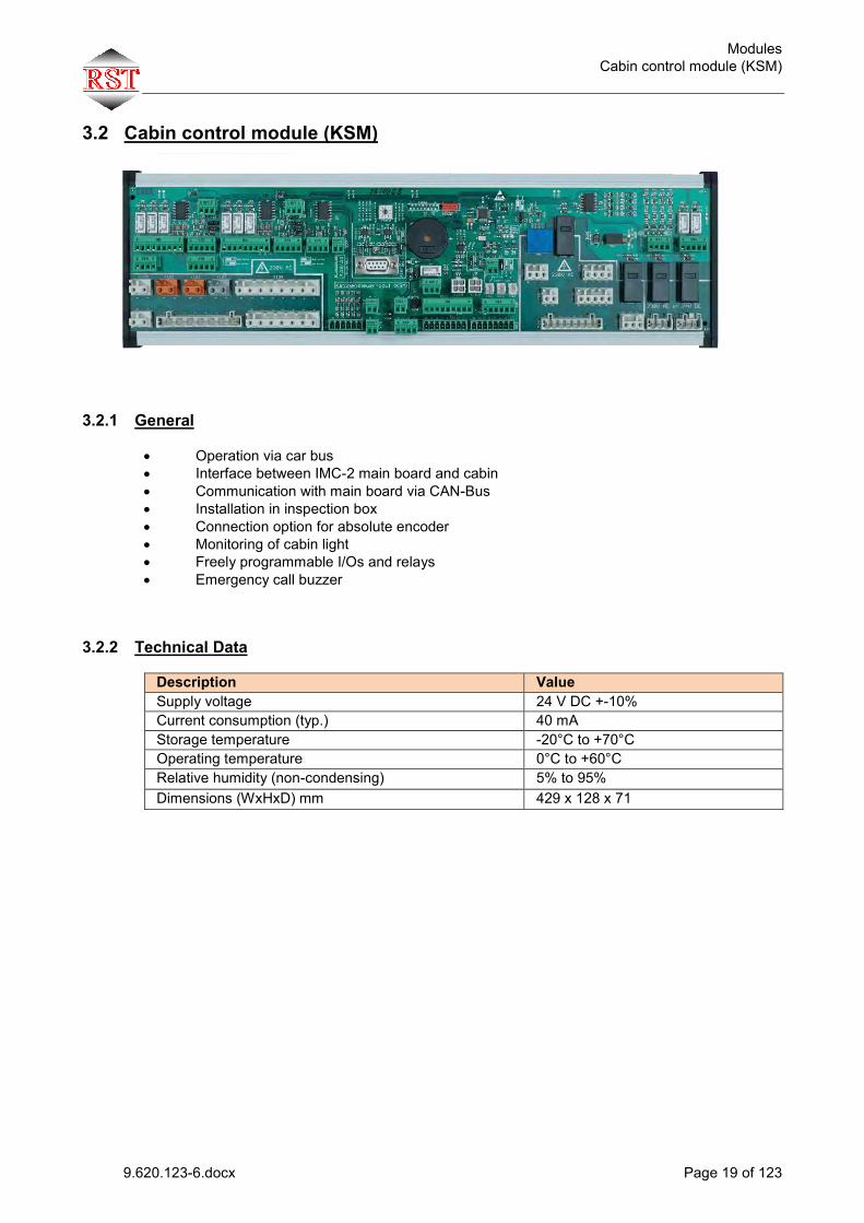
3.2 Cabin control module (KSM)
3.2.1 General Operation via car bus Interface between IMC-2 main board and cabin Communication with main board via CAN-Bus Installation in inspection box Connection option for absolute encoder Monitoring of cabin light Freely programmable I/Os and relays Emergency call buzzer
3.2.2 Technical Data
Description Value Supply voltage 24 V DC +-10% Current consumption (typ.) 40 mA Storage temperature -20°C to +70°C Operating temperature 0°C to +60°C Relative humidity (non-condensing) 5% to 95% Dimensions (WxHxD) mm 429 x 128 x 71

Modules Cabin control module (KSM)
9.620.123-6.docx Page 20 of 123
3.2.3 Jumper / rotary encoder switch
Name Function Jumper XJ2 Load measurement
On: Enable load measurement info via CAN Off:Disable load measurement info via CAN
Jumper XJ3
Level selection of light barrier inputs X72 Active-high / active-low
Jumper XJ4
Level selection of light barrier inputs X72 Active-high / active-low
Jumper XJ5
Level selection of light barrier inputs X75 Active-high / active-low
Jumper XJ6
Level selection of light barrier inputs X75 Active-high / active-low
Jumper XJ7 Encoder
On: Enable absolute position info via CAN. SSI encoder must be connected to X107. Off:Disable absolute position info via CAN.
Jumper XJ8
0..5V: Load measurement input voltage range (X81,XS1) 0..10V: Load measurement input voltage range (X81,XS1)
Jumper XJ9 Light Current
High: Cabin light current wide measurement range (effective value 1.2 A sine) Low:Cabin light current small measurement range (effective value 0.6 A sine) The sensitivity range can be adjusted depending on the light fixture by means of XJ9. In this way, even partial lighting failure can be detected (e.g. 2 lights out of 4 failed).
Rotary encoder switch S-ADRESS
Setting of node number
3.2.4 Special LEDs All universal inputs/outputs feature LEDs. With open terminals, the LED may glow slightly.
Name Colour State Description LD3 Error Yellow flashing Error has occurred LD4 Status Yellow flashing 0.5Hz
flashing 2 Hz No CAN receive telegram Node receives CAN telegrams
LD1 +24V Yellow +24 V board supply voltage LD2 +5V Yellow +5 V board supply voltage

Modules Cabin control module (KSM)
9.620.123-6.docx Page 21 of 123
3.2.5 Location of terminals / Layout

Modules Cabin control module (KSM)
9.620.123-6.docx Page 22 of 123
3.2.6 List of terminals Connector/Terminal Function X68 0 +24V 1 GND 2 Relay C (common terminal) 3 Open door relay 4 Close door relay 5 Shoving relay 6 Open door input (24V, neg. switching) 7 Closed door input (24V, neg. switching) 8 Reverse input (24V, neg. switching) X69 0 GND 1 GND 2 GND 3 GND X70 +24V 0 +24V 1 +24V 2 +24V 3 +24V 4 +24V supply for light barrier front/rear (X71,X72,X74,X75) X71 Light barrier 1, transmitter 0 +24V (voltage from X70.4) 1 GND 2 Data Tx/Rx (connection to X72.4) X72 Light barrier 1, receiver 0 +24V (voltage from X70.4) 1 GND 2 GND 3 Signal In 4 Data Tx/Rx (connection to X71.2) X73 0 +24V (voltage from X70.4) 1 GND 2 Relay K4-K7 C (common terminal) 3 Relay K4 NO 4 Relay K5 NO 5 Relay K7 NO 6 Input 1 (24V, neg. switching) 7 Input 2 (24V, neg. switching) 8 Input 3 (24V, neg. switching) X74 Light barrier 2, transmitter 0 +24V (voltage from X70.4) 1 GND 2 Data Tx/Rx (connection to X75.4)

Modules Cabin control module (KSM)
9.620.123-6.docx Page 23 of 123
X75 0 +24V 1 GND 2 GND 3 Signal In 4 Data Tx/Rx (connection to X74.2) X76 Universal inputs/outputs 0 +24V 1 I/O 24 2 I/O 32 3 GND X77 Shaft light switch 0 Input shaft light switch 1 GND shaft light switch X78 Inspection 0 GND Inspection 1 Input Inspection emergency stop (24V, neg. switching) 2 Input Inspection fast (24V, neg. switching) 3 Input Inspection down (24V, neg. switching) 4 Input Inspection up (24V, neg. switching) 5 Input Inspection on (24V, neg. switching) X79 Inspection fast 0 Input Inspection fast (24V, neg. switching) 1 GND Inspection X80 Cabin emergency call relay 0 Relay contact NC (normally closed) 1 Relay contact C (changeover) 2 Relay contact NO (normally open) X81 Load measurement 0 Signal 1 AGND (analogue GND) X82 Suspended cables power supply / zones 0 +24V battery 1 Emergency call 2 Zone switch 1 3 Zone switch 2 4 +24V from main board 5 +24V from main board 6 GND from main board 7 GND from main board X83 Wiring to internal panel module 0 +24V battery 1 Emergency call button 2 GND 3 Intercom wire 1A 4 Intercom wire 1B 5 Intercom wire 2A 6 Intercom wire 2B 7 Intercom wire 3A 8 Intercom wire 3B

Modules Cabin control module (KSM)
9.620.123-6.docx Page 24 of 123
X84 Zone switch 1/2 0 + 24V battery 1 Zone switch 1 2 Zone switch 2 3 GND X85 Cabin emergency call button 0 +24V battery 1 Emergency call button X86 Suspended cables data 0 Intercom wire 1A 1 Intercom wire 1B 2 Intercom wire 2A 3 Intercom wire 2B 4 Intercom wire 3A 5 Intercom wire 3B 6 CANL 7 CANH X87 Intercom on cabin 0 Intercom wire 1A 1 Intercom wire 1B 2 Intercom wire 2A 3 Intercom wire 2B 4 Intercom wire 3A 5 Intercom wire 3B
X88 Cabin lighting supply 0 PE 1 N 2 L
X89 Outlet supply+inspection box grounding 0 PE (inspection box grounding) 1 PE (inspection box grounding) 2 N 3 L
X90 Reserve 0 Reserve (permanent connection to X92.0) 1 N
X91 Door controller supply / three-phase door 0 L1 1 N 2 L2 3 PE 4 L3
X92 Suspended cables L1-L3
0 Reserve (permanent connection to X90.0) 1 L cabin lighting, outlet + fan 2 N cabin lighting, outlet + fan 3 L1 door 4 N door 5 L2 door

Modules Cabin control module (KSM)
9.620.123-6.docx Page 25 of 123
6 PE 7 L3 door X93 Active-high inputs 0 Input (active-high) 1 Input (active-high) 2 Input (active-high) 3 Input (active-high) X94 Relay for +24 V signals 0 +24V 1 GND 2 Relay K3+K4 C (common terminal) 3 Relay K3 NO (normally open) 4 Relay K6 NO (normally open)
X95 Fan supply 0 PE 1 N 2 L
X96 Relay for +24 V or 230V signals 0 Relay K1 NO (normally open contact) 1 Relay K1 C (changeover contact) 2 Relay K1 NC (normally closed contact)
X97 Relay for +24 V or 230V signals
0 Relay K2 NO (normally open contact) 1 Relay K2 C (changeover contact) 2 Relay K2 NC (normally closed contact)
X98 Safety circuit 0 Safety circuit, cabin limit switch 1 Safety circuit, cabin limit switch X99 Inspection 0 Input Inspection emergency stop (24V, neg. switching) 1 GND Inspection
X100 Safety circuit 0 Safety circuit, catch contact 1 Safety circuit, catch contact
X101 Safety circuit 0 Safety circuit, cabin door front limit switch 1 Safety circuit, cabin door front limit switch
X102 Safety circuit 0 Safety circuit, cabin door rear limit switch 1 Safety circuit, cabin door rear limit switch
X103 Safety circuit 0 Safety circuit, external emergency stop 1 Safety circuit, external emergency stop

Modules Cabin control module (KSM)
9.620.123-6.docx Page 26 of 123
X104 Safety circuit 0 Safety circuit, safety switch 1 Safety circuit, safety switch 2 Safety circuit, safety switch 3 Safety circuit, safety switch 4 Safety circuit, safety switch 5 Safety circuit, safety switch 6 Safety circuit, safety switch 7 Safety circuit, safety switch
X105 Safety circuit, suspended cables 0 Start of cabin safety circuit 1 End, limit switch 2 Door tapping 3 End, cabin door 4 To emergency stop switch 5 Return / bypass limit switch 6 To inspection switch 7 No inspection
X106 Safety circuit 0 Safety circuit, inspection + emergency stop 1 Safety circuit, inspection + emergency stop 2 Safety circuit, inspection + emergency stop 3 Safety circuit, inspection + emergency stop 4 Safety circuit, inspection + emergency stop 5 Safety circuit, inspection + emergency stop 6 Safety circuit, inspection + emergency stop X107 Absolute encoder input (D-SUB 9-pin, female) 1 +24V 2 GND 3 PRESET 4 RICHTUNG 5 n.c. 6 +Data 7 -Data 8 +Clock 9 -Clock X108 CAN X109 CAN XS1 RESERVED XS2 RESERVED XS3 RESERVED
Modules Cabin control module (KSM)
9.620.123-6.docx Page 27 of 123
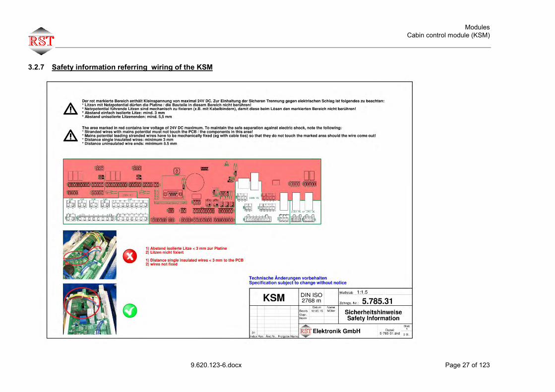
3.2.7 Safety information referring wiring of the KSM

Modules Universal Bus Module (UBM)
9.620.123-6.docx Page 28 of 123
3.3 Universal Bus Module (UBM)
3.3.1 General Operation via shaft or car bus Communication with main board via CAN-Bus Installation in external panel, for example 8 freely programmable I/Os, can be expanded to 32 I/Os using port expander module
3.3.2 Technical Data
Description Value Supply voltage 24 V DC +-10% Current consumption (typ.) 20 mA Storage temperature -20°C to +70°C Operating temperature 0°C to +60°C Relative humidity (non-condensing) 5% to 95% Dimensions (WxHxD) mm 58 x 56 x 16
3.3.3 Jumper / rotary encoder switch
Name Function Jumper XJ1
Selection, front/rear door side
Rotary encoder switch S_ADRESS_1
Setting of node number “unit position”
Rotary encoder switch S_ADRESS_10
Setting of node number “ten's position”

Modules Universal Bus Module (UBM)
9.620.123-6.docx Page 29 of 123
3.3.4 Special LEDs All universal inputs/outputs feature LEDs. With open terminals, the LED may glow slightly.
Name Colour State Description Error Yellow flashing Error has occurred Status
Yellow flashing 0.5Hz flashing 2 Hz
No CAN receive telegram Node receives CAN telegrams
3.3.5 Location of terminals / Layout
3.3.6 List of terminals Connector/Terminal Function XIO1 Universal inputs/outputs (10-pin strip) 1 I/O1 (24V, neg. switching) 2 I/O2 (24V, neg. switching) 3 I/O3 (24V, neg. switching) 4 I/O4 (24V, neg. switching) 5 I/O5 (24V, neg. switching) 6 I/O6 (24V, neg. switching) 7 I/O7 (24V, neg. switching) 8 I/O8 (24V, neg. switching) 9 GND 10 +24V XIO2 Universal inputs/outputs (4-pin screw terminal) 7 I/O7 (24V, neg. switching) 8 I/O8 (24V, neg. switching) GND GND +24 V +24V X-BUS1 CAN X-BUS2 CAN
Modules Port Expander Module (PEM)
9.620.123-6.docx Page 30 of 123
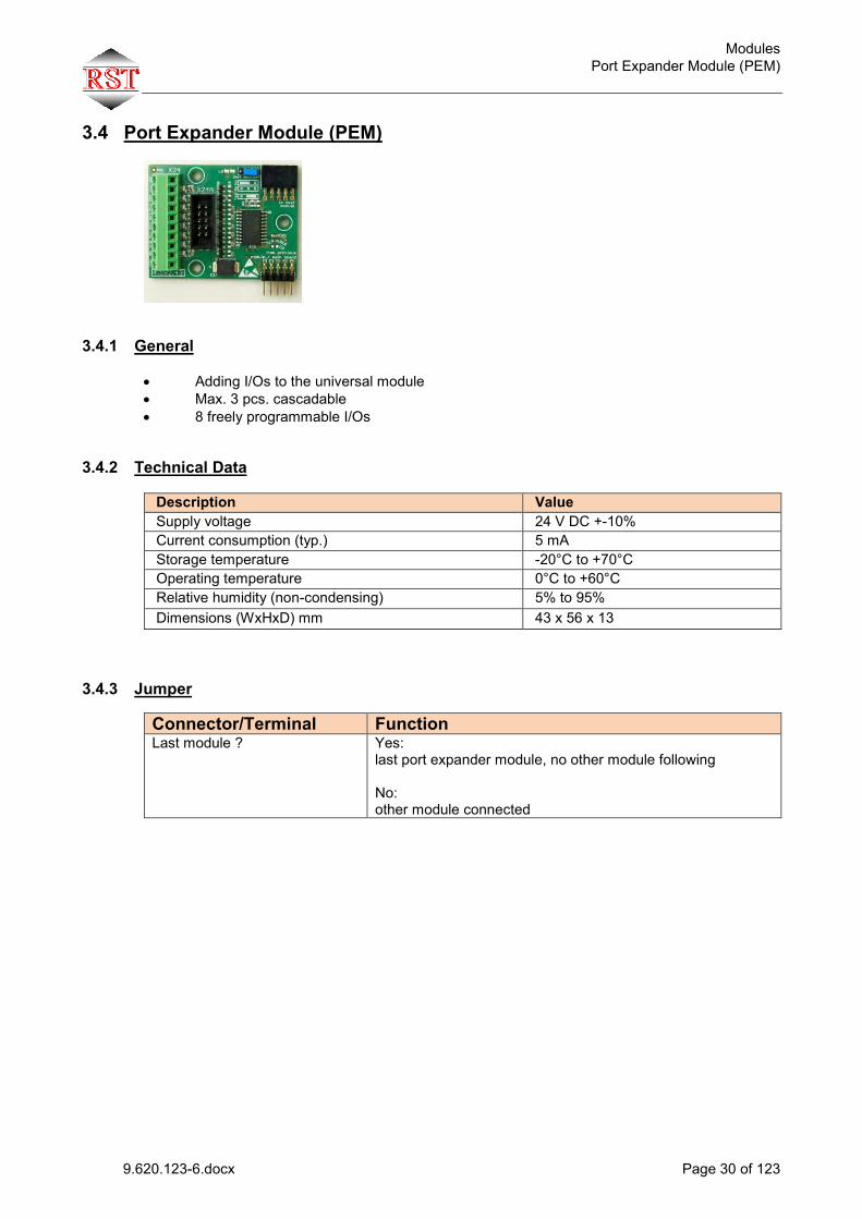
3.4 Port Expander Module (PEM)
3.4.1 General Adding I/Os to the universal module Max. 3 pcs. cascadable 8 freely programmable I/Os
3.4.2 Technical Data
Description Value Supply voltage 24 V DC +-10% Current consumption (typ.) 5 mA Storage temperature -20°C to +70°C Operating temperature 0°C to +60°C Relative humidity (non-condensing) 5% to 95% Dimensions (WxHxD) mm 43 x 56 x 13
3.4.3 Jumper Connector/Terminal Function Last module ? Yes:
last port expander module, no other module following No: other module connected

Modules Port Expander Module (PEM)
9.620.123-6.docx Page 31 of 123
3.4.4 Location of terminals / Layout 3.4.5 List of terminals
Connector/Terminal Function X24 Universal inputs/outputs (10-pin screw terminal) +24 V Power supply +24 V IO 9 I/O9 (24V, neg. switching) IO 10 I/O10 (24V, neg. switching) IO 11 I/O11 (24V, neg. switching) IO 12 I/O12 (24V, neg. switching) IO 13 I/O13 (24V, neg. switching) IO 14 I/O14 (24V, neg. switching) IO 15 I/O15 (24V, neg. switching) IO 16 I/O16 (24V, neg. switching) GND Ground X24A Universal inputs/outputs (10-pin strip) 1 I/O (24V, neg. switching) 2 I/O (24V, neg. switching) 3 I/O (24V, neg. switching) 4 I/O (24V, neg. switching) 5 I/O (24V, neg. switching) 6 I/O (24V, neg. switching) 7 I/O (24V, neg. switching) 8 I/O (24V, neg. switching) 9 GND 10 +24V

Modules Car position indicator module (EAM)
9.620.123-6.docx Page 32 of 123
3.5 Car position indicator module (EAM)
3.5.1 General 2 design variants:
L with matrix display 64x64 S with matrix display 40x40
Operation via shaft or car bus Communication with main board via CAN-Bus
8 freely programmable I/Os
3.5.2 Technical Data
Description Value Supply voltage 24 V DC +-10% Current consumption (typ.) 20 mA Storage temperature -20°C to +70°C Operating temperature 0°C to +60°C Relative humidity (non-condensing) 5% to 95% Dimensions L approx. (WxHxD) mm Dimensions S approx. (WxHxD) mm
110 x 70 x 30
Display size L (WxH) mm 64 x 64 Display size S (WxH) mm 40 x 40
3.5.3 Jumper / rotary encoder switch
Name Function Jumper XJ1
Selection, front/rear door side
Rotary encoder switch S-ADRESS_1
Setting of node number “unit position”
Rotary encoder switch S-ADRESS_10
Setting of node number “ten's position”
3.5.4 Special LEDs All universal inputs/outputs feature LEDs. With open terminals, the LED may glow slightly.
Name Colour State Description Error Red flashing Error has occurred Status
Yellow flashing 0.5Hz flashing 2 Hz
No CAN receive telegram Node receives CAN telegrams

Modules Car position indicator module (EAM)
9.620.123-6.docx Page 33 of 123
3.5.5 Location of terminals / Layout
3.5.6 List of terminals
Connector/Terminal Function X132 and X132A Universal inputs/outputs (10-pin strip) 0 1 I/O1 (24V, neg. switching) 1 2 I/O2 (24V, neg. switching) 2 3 I/O3 (24V, neg. switching) 3 4 I/O4 (24V, neg. switching) 4 5 I/O5 (24V, neg. switching) 5 6 I/O6 (24V, neg. switching) 6 7 I/O7 (24V, neg. switching) 7 8 I/O8 (24V, neg. switching) 8 9 GND 9 10 +24V X130 CAN X131 CAN
EAM-S Stecker/Klemme Funktion X138 and X138A Universal Ein-Ausgänge (Stiftleiste 10 pol) 0 1 I/O1 (24V, neg. switching) 1 2 I/O2 (24V, neg. switching) 2 3 I/O3 (24V, neg. schaltend) 3 4 I/O4 (24V, neg. schaltend) 4 5 I/O5 (24V, neg. schaltend) 5 6 I/O6 (24V, neg. schaltend) 6 7 I/O7 (24V, neg. schaltend) 7 8 I/O8 (24V, neg. schaltend) 8 9 GND 9 10 +24V X136 CAN X137 CAN

Modules Car operation panel (ITM)
9.620.123-6.docx Page 34 of 123
3.6 Car operation panel (ITM)
3.6.1 General Operation via car bus Communication with main board via CAN-Bus Mounted in cabin control panel freely programmable I/Os Emergency lighting for cabin Overload buzzer Note: The integrated emergency lighting can provide for the 5 Lux illumination required per EN81-20 up to a cabin diagonal of approx. 1.4 meters. In the case of larger cabins, additional measures must be taken to ensure sufficient illumination.
3.6.2 Technical Data
Description Value Supply voltage 24 V DC +-10% Current consumption (typ.) 25 mA Storage temperature -20°C to +70°C Operating temperature 0°C to +60°C Relative humidity (non-condensing) 5% to 95% Dimensions (WxHxD) 108 x 130 x 26 (BS)
108 x 99 x 26 (Schäfer) ´
3.6.3 Rotary encoder switch
Name Function S-ADRESS Setting of node number

Modules Car operation panel (ITM)
9.620.123-6.docx Page 35 of 123
3.6.4 Special LEDs All universal inputs/outputs feature LEDs. With open terminals, the LED may glow slightly.
Name Colour State Description LD1 Error Yellow flashing Error has occurred LD2 Status Yellow flashing 0.5 Hz
flashing 2 Hz No CAN receive telegram Node receives CAN telegrams
LD8 +24V Yellow +24 V board supply voltage LD9 +5V Yellow +5 V board supply voltage
3.6.5 Location of terminals / Layout
Modules Car operation panel (ITM)
9.620.123-6.docx Page 36 of 123
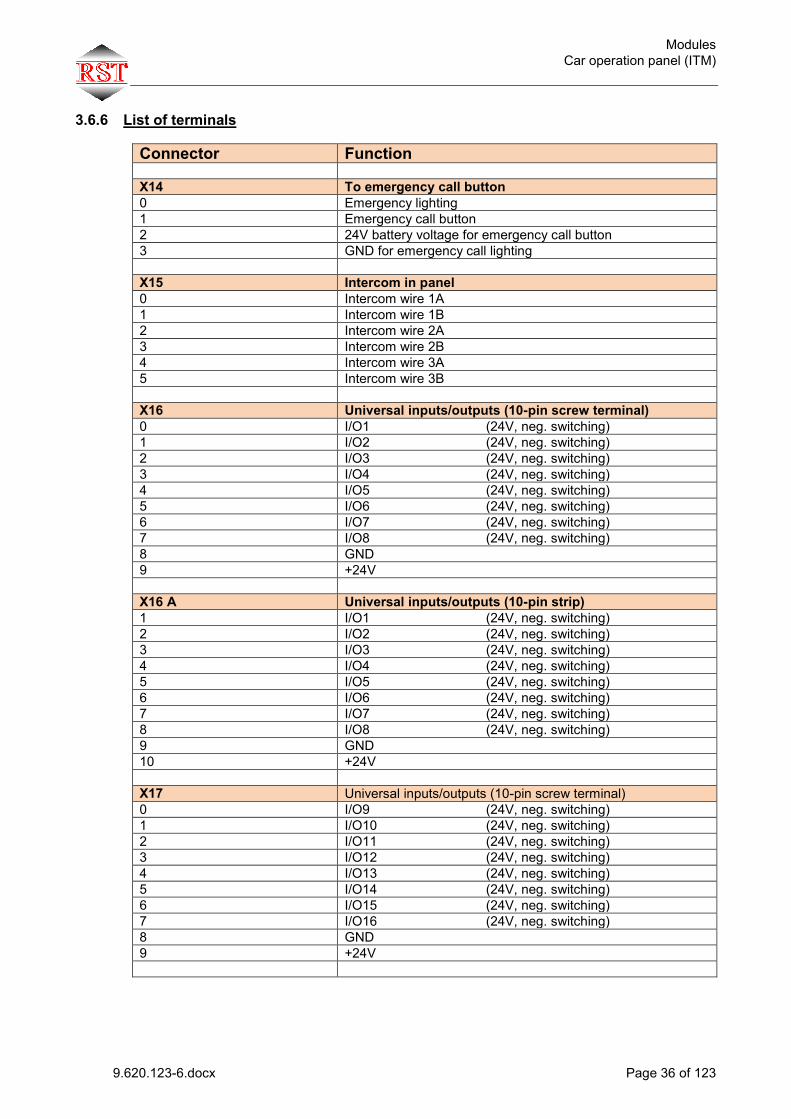
3.6.6 List of terminals Connector Function X14 To emergency call button 0 Emergency lighting 1 Emergency call button 2 24V battery voltage for emergency call button 3 GND for emergency call lighting X15 Intercom in panel 0 Intercom wire 1A 1 Intercom wire 1B 2 Intercom wire 2A 3 Intercom wire 2B 4 Intercom wire 3A 5 Intercom wire 3B X16 Universal inputs/outputs (10-pin screw terminal) 0 I/O1 (24V, neg. switching) 1 I/O2 (24V, neg. switching) 2 I/O3 (24V, neg. switching) 3 I/O4 (24V, neg. switching) 4 I/O5 (24V, neg. switching) 5 I/O6 (24V, neg. switching) 6 I/O7 (24V, neg. switching) 7 I/O8 (24V, neg. switching) 8 GND 9 +24V X16 A Universal inputs/outputs (10-pin strip) 1 I/O1 (24V, neg. switching) 2 I/O2 (24V, neg. switching) 3 I/O3 (24V, neg. switching) 4 I/O4 (24V, neg. switching) 5 I/O5 (24V, neg. switching) 6 I/O6 (24V, neg. switching) 7 I/O7 (24V, neg. switching) 8 I/O8 (24V, neg. switching) 9 GND 10 +24V X17 Universal inputs/outputs (10-pin screw terminal) 0 I/O9 (24V, neg. switching) 1 I/O10 (24V, neg. switching) 2 I/O11 (24V, neg. switching) 3 I/O12 (24V, neg. switching) 4 I/O13 (24V, neg. switching) 5 I/O14 (24V, neg. switching) 6 I/O15 (24V, neg. switching) 7 I/O16 (24V, neg. switching) 8 GND 9 +24V

Modules Car operation panel (ITM)
9.620.123-6.docx Page 37 of 123
X17 A Universal inputs/outputs (10-pin strip) 1 I/O9 (24V, neg. switching) 2 I/O10 (24V, neg. switching) 3 I/O11 (24V, neg. switching) 4 I/O12 (24V, neg. switching) 5 I/O13 (24V, neg. switching) 6 I/O14 (24V, neg. switching) 7 I/O15 (24V, neg. switching) 8 I/O16 (24V, neg. switching) 9 GND 10 +24V X18 Universal inputs/outputs (10-pin screw terminal) 0 I/O17 (24V, neg. switching) 1 I/O18 (24V, neg. switching) 2 I/O19 (24V, neg. switching) 3 I/O20 (24V, neg. switching) 4 I/O21 (24V, neg. switching) 5 I/O22 (24V, neg. switching) 6 I/O23 (24V, neg. switching) 7 I/O24 (24V, neg. switching) 8 GND 9 +24V X18A Universal inputs/outputs (10-pin strip) 1 I/O17 (24V, neg. switching) 2 I/O18 (24V, neg. switching) 3 I/O19 (24V, neg. switching) 4 I/O20 (24V, neg. switching) 5 I/O21 (24V, neg. switching) 6 I/O22 (24V, neg. switching) 7 I/O23 (24V, neg. switching) 8 I/O24 (24V, neg. switching) 9 GND 10 +24V X19 Universal inputs/outputs (10-pin screw terminal) 0 I/O25 (24V, neg. switching) 1 I/O26 (24V, neg. switching) 2 I/O27 (24V, neg. switching) 3 I/O28 (24V, neg. switching) 4 I/O29 (24V, neg. switching) 5 I/O30 (24V, neg. switching) 6 n.c (reserved for emergency lighting) 7 n.c (reserved for buzzer) 8 GND 9 +24V X19A Universal inputs/outputs (10-pin strip) 1 I/O25 (24V, neg. switching) 2 I/O26 (24V, neg. switching) 3 I/O27 (24V, neg. switching) 4 I/O28 (24V, neg. switching) 5 I/O29 (24V, neg. switching) 6 I/O30 (24V, neg. switching) 7 n.c. (reserved for emergency lighting) 8 n.c. (reserved for buzzer) 9 GND 10 +24V
Modules Car operation panel (ITM)
9.620.123-6.docx Page 38 of 123
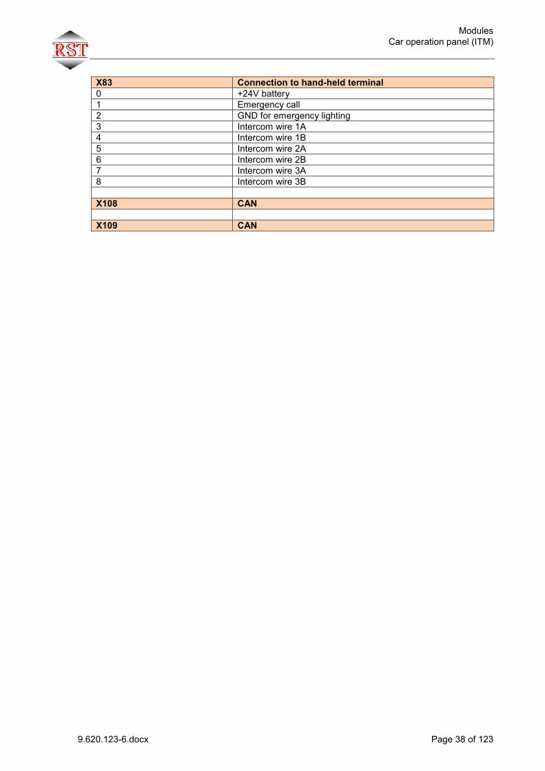
X83 Connection to hand-held terminal 0 +24V battery 1 Emergency call 2 GND for emergency lighting 3 Intercom wire 1A 4 Intercom wire 1B 5 Intercom wire 2A 6 Intercom wire 2B 7 Intercom wire 3A 8 Intercom wire 3B X108 CAN X109 CAN

Modules Bluetooth module (BTM)
9.620.123-6.docx Page 39 of 123
3.7 Bluetooth module (BTM)
3.7.1 General Operation via car bus Enables wireless connection between cabin and IMC-2 for operation of LiftControl or
Display-APP Communication with main board via CAN-Bus Installation in inspection box, for example
3.7.2 Technical Data
Description Value Supply voltage 24 V DC +-10% Current consumption (typ.) 40 mA Storage temperature -20°C to +70°C Operating temperature 0°C to +60°C Relative humidity (non-condensing) 5% to 95% Dimensions (WxHxD) mm 64 x 73 x 16
3.7.3 Jumper / rotary encoder switch
Name Function Rotary encoder switch S_ADRESS_1
Setting of node number
3.7.4 Special LEDs
Name Colour State Description Conn. status Yellow flashing 10Hz
flashing 1 Hz Module waiting for connection
Conn.
Blue Module connected to PC or mobile
Error Red flashing Error has occurred Status
Yellow flashing 0.5Hz flashing 2 Hz
No CAN receive telegram Node receives CAN telegrams

Modules Hand-held terminal
9.620.123-6.docx Page 40 of 123
3.8 Hand-held terminal
3.8.1 General Operation via shaft or car bus Remote adjustment and diagnosis Can be connected to any bus port both in the shaft and in the car bus. If operating at the car bus, the VVVF inverter can also be remote-controlled
3.8.2 Technical Data
Description Value Supply voltage 24 V DC +-10% Current consumption (typ.) 30 mA Storage temperature -20°C to +70°C Operating temperature 0°C to +60°C Relative humidity (non-condensing) 5% to 95% Dimensions (WxHxD) 118 x 227 x 47
´

Modules Safety monitoring module
9.620.123-6.docx Page 41 of 123
3.9 Safety monitoring module
3.9.1 General The safety monitoring module enables bypassing the door and lock contact in the safety circuit via two independently operating door-zone switches. The circuit monitors the closed/open changeover status of the two zone switches. If one or both zone switches do not change their status in the test cycle, this will be interpreted as an error and the door/lock bypass will not be activated. In addition, an output will be switched for the controller to evaluate the error.
3.9.2 Technical Data
Description Value Supply voltage 24 V DC +-10% Current consumption (typ.) 60 mA Storage temperature -20°C to +70°C Operating temperature 0°C to +60°C Relative humidity (non-condensing) 5% to 95% Dimensions (WxHxD) 99 x 128 x 67

Modules Safety monitoring module
9.620.123-6.docx Page 42 of 123
3.9.3 Location of terminals / Layout
3.9.4 List of terminals
Terminal Type Note X20
200 Supply +24V +-10% 201 Input Zone switch 1 (connected to GND) 202 Input Zone switch 2 (connected to +24V)
203 Input Start of test cycle
0V: no test +24V: Test active
204 Output Info for controller on state of safety monitoring module 0V: ok +24V: Error
205 Input Info on cabin speed Cabin speed > 0.3m/s: 0V Cabin speed < 0.3m/s: +24V
206 Supply voltage, ground GND X21 Potential-free relay contact max. 3 A at 230 VAC rated voltage
210 Safety circuit 211 Safety circuit 212 Safety circuit
X22 Potential-free relay contact max. 3 A at 24 VDC rated voltage 220 Relay contact Normally open contact of K3 221 Relay contact Normally open contact of K3

Modules
9.620.123-6.docx Page 43 of 123
3.9.5 Test Via test switch S1 “Hanging” of zone switches is simulated. Test procedure: (Test of monitoring of zone switch 1) 1. The lift is in flush position, both zone switches are closed. 2. Relays K1 and K2 energized, K4 is deenergized. 3. Set test switch S1 to “Test ZS1” position ( zone switch 1 is bypassed permanently). 4. Start travel operation to any floor. 5. Once the test cycle has started, K4 cannot be energized again when landing in the door
zone (contact of K1 is open). As a result, K2 can no longer be energized. 6. After stopping, the feedback to the controller is “0”. For this reason, no more travel
operations are possible (because K2 is deenergized). The door/lock contact bypass is ineffective (contact of K2 in safety circuit open).
7. Set test switch S1 to “Standard” position again. 8. Switch control voltage supply off and on again. 9. The controller is ready for operation again. (Test of monitoring of zone switch 2) 10. The lift is in flush position, both zone switches are closed. 11. Relays K1 and K2 energized, K4 is deenergized. 12. Set test switch S1 to “Test ZS2” position ( zone switch 2 is bypassed permanently). 13. Start travel operation to any floor. 14. K1 is deenergized once the zone is left. 15. K2 remains energized (latch). 16. K4 is deenergized by normally open contact of K2. 17. When entering the zone, K4 cannot be energized because K2 is still energized. As a
result, K1 cannot be energized. 18. After stopping, the feedback to the controller is “0” (because K1 is deenergized). No more
travel operations are possible. The door/lock contact bypass is ineffective (contact of K1 in safety circuit open).
19. Set test switch S1 to “Standard” position again 20. Switch control voltage supply off and on again. 21. The controller is ready for operation again
(Test K3) 22. The lift is in flush position 23. Relay K3 is energized. 24. Start travel operation at v < 0.3 m/s relay K3 must not be deenergized 25. Start travel operation at v > 0.3 m/s relay K3 must be deenergized once the speed
exceeds 0.3 m/s, and re-energized when the speed drops below 0.3 m/s again (Info: the switching signal for relay K3 comes from the IMC-2 controller)
3.9.6 Activation in controller Generally the safety monitoring module is activated in the menu Setup - Plant - Safety monitoring module ? = 1 (Yes) .

Modules CAN bus
9.620.123-6.docx Page 44 of 123
3.10 CAN bus
3.10.1 General All modules are networked via CAN bus. Generally, 3 separate buses are used: Car bus Standard Shaft bus1 Standard Shaft bus2 In groups with 2 shaft daisy chains By default, car bus and shaft bus1 are wired in the case of single lifts. The bus connectors may only be plugged when the system is deenergized ! Free bus terminals at the end of the line must be provided with a terminator !
3.10.2 Technical Data
Description Value Supply voltage 24 V DC +-10% Operating temperature 0°C to +60°C Relative humidity (non-condensing) 5% to 95% Maximum number of nodes per bus 64
3.10.3 Setting the node IDs The node number (identifier) is set by means of a rotary encoder switch. The first node corresponds to switch position “1”. In the universal bus module, an additional rotary encoder switch is provided since the number of nodes may involve two digits (ten's position, unit position). Generally, the nodes are preset and labelled by RST.

Modules Travelling cable
9.620.123-6.docx Page 45 of 123
3.11 Travelling cable
3.11.1 General All connectors may only be plugged when the system is deenergized ! The shield of the travelling cable mus t be connect toe earth in the cabinet
3.11.2 Technical Data
Description Value Supply voltage 24 V DC +-10%
230 V AC +-10% Operating temperature 0°C to +60°C Relative humidity (non-condensing) 5% to 95%

Modules Travelling cable
9.620.123-6.docx Page 46 of 123
3.11.3 Wire allocation
IMC-2 Connector/Terminal
Suspended cables Wire no.
Cabin (KSM) Connector/Terminal Function
X1.101 1 X92.0 Reserve X1.102 2 X92.1 L-Lighting X1.103 3 X92.2 N-Lighting
Hig
h vo
ltage
400
/230
VAC
X1.104 4 X92.3 L1-Door1 X1.105 5 X92.4 N-Door1 X1.106 6 X92.5 L2-Door1 X1.PE PE X92.6 PE X1.107 7 X92.7 L3-Door1 X1.108 8 X105.0 Safety circuit X1.109 9 X105.1 Safety circuit X1.110 10 X105.2 Safety circuit X1.111 11 X105.3 Safety circuit X1.112 12 X105.4 Safety circuit X1.113 13 X105.5 Safety circuit X1.114 14 X105.6 Safety circuit X1.115 15 X105.7 Safety circuit X1.116 16 X82.4 24V
Low
vol
tage
<=
24
VDC
X1.117 17 X82.5 24V X1.118 18 X82.6 0V X1.119 19 X82.7 0V X1.120 20 X82.0 24V Bat. X1.121 21 X82.1 Emergency call X1.122 22 X82.2 Zone1 X1.123 23 X82.3 Zone2 X1.124 24 X2.124 Safety circuit
Hig
h vo
ltage
40
0/23
0V
AC
X1.125 25 X2.125 Safety circuit X1.126 26 X2.126 Reserve X1.127 27 X2.127 Reserve X1.BN BN (1.1) X86.0 Intercom1
Low
vol
tage
<=
24
VDC
X1.WS WS (1.2) X86.1 Intercom2 X1.GN GN (2.1) X86.2 Intercom3 X1.WS WS (2.2) X86.3 Intercom4 X1.OR OR (3.1) X86.4 Intercom5 X1.WS WS (3.2) X86.5 Intercom6 X1.BL BL (4.1) X86.6 CAN-Bus Low X1.WS WS (4.2) X86.7 CAN-Bus High X1.blank

Menu and operation General
9.620.123-6.docx Page 47 of 123
4 Menu and operation
4.1 General The IMC controller is operated via four buttons. Button Select displayed menu item and open submenus; confirm entries and save edited
parameters (“Enter”) Button Leave submenus; cancel changes („Cancel“). Button Move in menu level; increase values Button Move in menu level; reduce values Generally there are different access levels for the menus. By default, the parameters covering 90% of the applications are visible. For special functions, another menu access level can be added. To do this, press buttons + simultaneously for 2 seconds. In the following descriptions, they are marked with the following symbols:
☻ Standard menu.
☺ Extended menu. Note: Different parameters are shown in the menu depending on the set drive type.
*S : Parameter only shown in the case of a cable lift *H : Parameter only shown in the case of a hydraulic lift
Parameters can generally not be changed during travel operations !
4.2 Start screen
The start screen is displayed immediately after startup. It has the following layout: Line 1: Operating state Line 2: Safety circuit and various status symbols Line 3: Current floor, cabin speed, position referred to next floor Line 4: Destination floor, direction, front door, rear door (if applicable) If an error occurs, it is displayed in the 2 menu lines at the bottom.
Example: Return operation
Example: Normal travel operation
Example: Error in SSI encoder connection

Menu and operation Entering parameter values
9.620.123-6.docx Page 48 of 123
4.3 Entering parameter values
Press to activate “Edit mode”.
In the display, you will now see the current parameter value, in the fourth line, you can change the value. Press to increase the value. Press to reduce it.
The setting range is limited by the minimum/maximum value of the relevant parameter. Once the desired parameter value is reached, press to apply it. Press to cancel.
4.4 Selection lists
In some menus, you can scroll through lists to select a setting. In these lists, the current setting is marked by a "*" symbol after the list entry.

Menu and operation General menu structure
9.620.123-6.docx Page 49 of 123
4.5 General menu structure
Settings Unit Landing Call Type Encoder Encoder-Type Encoder Direction encoder via CAN(1) Zone Length Pulley Circum. Number of Floors Door Bypass Red.SpeedControl Nom. Speed of Unit Term. Settings I/O Input Output Drive Drive Type Times On Delay Hyd. Off Delay Hyd. Delay DSV Waittime TOR Star/Delta-Time Brake Drop Time Contactor Drop Delay Motor Fan Run Time Relevelling Delay Brake 2 Delay Time ZS/ZB Relevelling Position Reference Floor Settings Floor 1 Position Door Side Floor 2 Position Door Side ..... ..... Decel.V4 Up Decel.V4 Down Decel.V3 Up Decel.V3 Down Decel.V2 Up Decel.V2 Down Decel. Dist. V4 Decel. Dist. V3 Decel. Dist. V2 Switch Off V0 Up Switch Off V0 Down Relevel On Relevel Off Relevel ext. On Relevel On

Menu and operation General menu structure
9.620.123-6.docx Page 50 of 123
Relevel On Relevel Off Relevel Off Insp.Stop Up Insp.Stop Down Insp.Always Fast ? Level Adjust Zone Hysterisis Encoder Zero Pos. Learn Run Learn Run Auto. Learn Run Manual Doors Pre Opening Doors Doors Collective Lock+Bolt Magnet F+R Lock+Bolt Max.Time Separation Door? Lock pause close Lock pause open Door Para. Front Door Type LR Test=>Start LR Status=>Run Light Ray w. Reset? Door Time Car Door Time Landing Time Open no Call Reversal Time Photocell Photocell Ext.Time Door Runtime Monitor Reversal Time Loading Time Nudging Time Open Limit Front Close Limit Front Door Run Time =>Open Door Run Time=>Close Mot.Off Door Open Mot.Off Door Closed Door Revers.Cont Door Pos.at Floor Door learning? Door Para. Rear ..see Door Para front Controller Timer Times Lock Debounce Time Start Delay Car Fan Run Time Car Light Off Time ?Kabine Hier OnDelay? Priority Car Priority Time Land. Priority Time Landing Priority <C>Car Call w. Prio.

Menu and operation General menu structure
9.620.123-6.docx Page 51 of 123
Special Functions Fire Evacuation Fire Evac.Type Fire Evac.1 Floor Door Pos.at Floor Fire Evac.2 Floor Door Pos.at Floor Emerg.Power Emerg.Powerdr.Type Floor Door Pos.at Floor Stutter Brake=>Mode Out Of Order Floor Door Pos.at Floor Switch Off Hard/Soft Floor Door Pos.at Floor Parking Standard Parking? Parking Floor Parking Time Door Pos.at Floor Door Parking Hydr VIP VIP 1 Desti.Floor VIP 1 Door Pos. VIP 2 Desti.Floor VIP 2 Door Pos. VIP Time Reserved only when empty Sel.LandCallContr KitchenControl V01 KSt CallEnableTime KSt SignalTime Ramp Operation Limit Top Limit Bottom Creep Dist. Display/Gong Pos.Indicator Floor Text Language Displaymode Floor Changes Scroll Speed Change at Target? Disp.SpecDrive? Landing Disp.Binary
Cab.Target.Land.Dist Gong-Functions Gong.Dist.to Floor Gong at Land. Blinking Approach Range Cab.Stand Lock w. Inv. Error
Menu and operation General menu structure
9.620.123-6.docx Page 52 of 123
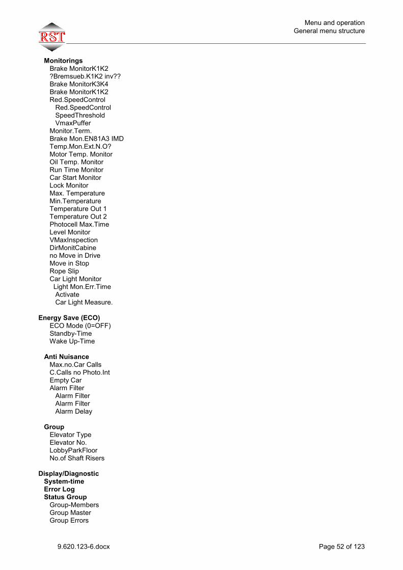
Monitorings Brake MonitorK1K2 ?Bremsueb.K1K2 inv?? Brake MonitorK3K4 Brake MonitorK1K2 Red.SpeedControl Red.SpeedControl SpeedThreshold VmaxPuffer Monitor.Term. Brake Mon.EN81A3 IMD Temp.Mon.Ext.N.O? Motor Temp. Monitor Oil Temp. Monitor Run Time Monitor Car Start Monitor Lock Monitor Max. Temperature Min.Temperature Temperature Out 1 Temperature Out 2 Photocell Max.Time Level Monitor VMaxInspection DirMonitCabine no Move in Drive Move in Stop Rope Slip Car Light Monitor Light Mon.Err.Time Activate Car Light Measure. Energy Save (ECO) ECO Mode (0=OFF) Standby-Time Wake Up-Time Anti Nuisance Max.no.Car Calls C.Calls no Photo.Int Empty Car Alarm Filter Alarm Filter Alarm Filter Alarm Delay Group Elevator Type Elevator No. LobbyParkFloor No.of Shaft Risers Display/Diagnostic System-time Error Log Status Group Group-Members Group Master Group Errors
Menu and operation General menu structure
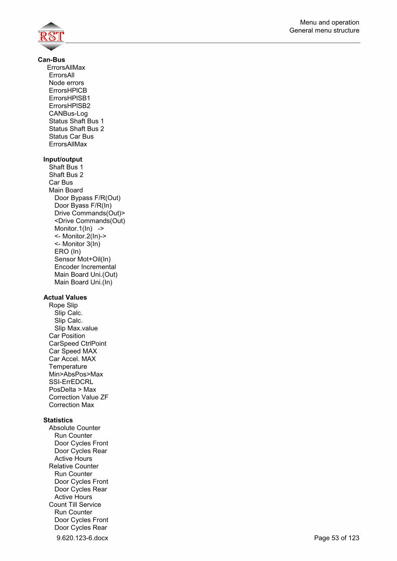
9.620.123-6.docx Page 53 of 123
Can-Bus ErrorsAllMax ErrorsAll Node errors ErrorsHPlCB ErrorsHPlSB1 ErrorsHPlSB2 CANBus-Log Status Shaft Bus 1 Status Shaft Bus 2 Status Car Bus ErrorsAllMax Input/output Shaft Bus 1 Shaft Bus 2 Car Bus Main Board Door Bypass F/R(Out) Door Byass F/R(In) Drive Commands(Out)> <Drive Commands(Out) Monitor.1(In) -> <- Monitor.2(In)-> <- Monitor 3(In) ERO (In) Sensor Mot+Oil(In) Encoder Incremental Main Board Uni.(Out) Main Board Uni.(In) Actual Values Rope Slip Slip Calc. Slip Calc. Slip Max.value Car Position CarSpeed CtrlPoint Car Speed MAX Car Accel. MAX Temperature Min>AbsPos>Max SSI-ErrEDCRL PosDelta > Max Correction Value ZF Correction Max Statistics Absolute Counter Run Counter Door Cycles Front Door Cycles Rear Active Hours Relative Counter Run Counter Door Cycles Front Door Cycles Rear Active Hours Count Till Service Run Counter Door Cycles Front Door Cycles Rear

Menu and operation General menu structure
9.620.123-6.docx Page 54 of 123
Active Hours Call Statistics Actual Calls I=Car A=Landing Software Version Bootloader Version Status ECO Mode Actual Faults System Inverter Control Language Time/Date Set Time/Date Day Weekday (Sun=1) Month Year (20xx) Hours Minutes Save Data? <E> Code Enter Code Change Code Code Present Menu-Access USB Host Import Export Firmware Hex-File from Error Code Star/Delta-Time Flash Loader Start from PC? (E) Start from USB? (E) Service Calls Random Calls Activate Call no. (act) Calls (Remain.) Run Interval Run Top/Bottom Disable Car Call F Disable Land.Call F Disable Car Call R Disable Land. Call R Installation.Mode

Menu and operation General menu structure
9.620.123-6.docx Page 55 of 123
Show Services TüV / Test Run Time Min. Top/Bott.Limit Test Buffer-Test Overload Off EN81-A3 Test Run No Lockup SC Nothalt-Test Calibration Inverter Service Interval Runs Till Service Door Cycles Front Door Cycles Rear Active Hours Set Interval Erase Rel. Counter ..Erase With <E> Erase Call Counter ..Erase With <E> Data Interface Baudrate PC/Modem Remote Access

Menu and operation Setup menu
9.620.123-6.docx Page 56 of 123
4.6 Setup menu
4.6.1 Plant
When setting up the plant data, note that some of these parameters will require a new Learn Run. This will be indicated when you open the menu.
Parameter Description Setting range Landing Call Type ☻
2KS 1KS RE 1KS RU Direct travel
The lift will stop with each Up call in Up direction and with each Down call in Down direction. All calls in travel direction will be considered. Once there is no more call in travel direction, the search direction is reversed and current calls in the new travel direction will be processed. The lift will stop with each call in Up and Down direction. Outside calls will only be processed once there is no more inside command. During this time, Occupied will be displayed.
Encoder ☻
Encoder type WDGA58B-10-1213 Shaft incremental encoder Motor incremental encoder ELGO LIMAX02 SSI
Wachendorff absolute encoder 1024 pulse encoder HTL. Pre-limit switch required. Motor rotary encoder. Pre-limit switch required. Absolute shaft information system ELGO
Encoder direction ☻ 0: Normal 1: Inverted
0 .. 1
Encoder via CAN ☻ 0: no encoder info received via CAN 1: Position info received via CAN bus
0 .. 1
Zone Length ☻ All sheets must have the same length 0 .. 2000 mm
Pulley Circum. ☻ Circumference = 3.14 * diameter [mm] 0 .. 3000 mm
Number of Floors ☻ Number of floors 1 .. 32
Door Bypass ☻ Activation of safety monitoring module 0 .. 1
Decel.Control ☻ Activation of the decelaration supervision Separate documentation at RST
0 .. 1
Nom. Speed of Unit ☻ Entered in mm/sec 0.1 .. 4 m/s
Configuration I/Os ☻ Configuration of input/output terminals
Menu and operation Setup menu
9.620.123-6.docx Page 57 of 123
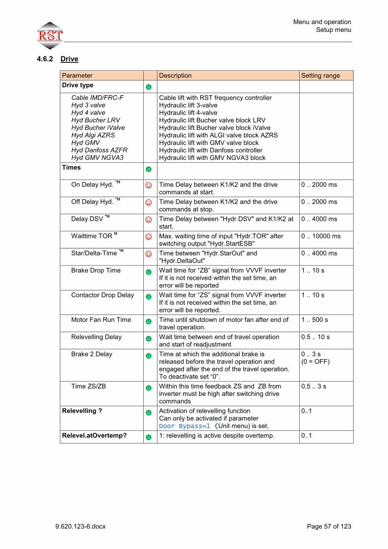
4.6.2 Drive
Parameter Description Setting range Drive type ☻
Cable IMD/FRC-F Hyd 3 valve Hyd 4 valve Hyd Bucher LRV Hyd Bucher iValve Hyd Algi AZRS Hyd GMV Hyd Danfoss AZFR Hyd GMV NGVA3
Cable lift with RST frequency controller Hydraulic lift 3-valve Hydraulic lift 4-valve Hydraulic lift Bucher valve block LRV Hydraulic lift Bucher valve block iValve Hydraulic lift with ALGI valve block AZRS Hydraulic lift with GMV valve block Hydraulic lift with Danfoss controller Hydraulic lift with GMV NGVA3 block
Times
☻
On Delay Hyd. *H ☺ Time Delay between K1/K2 and the drive commands at start.
0 .. 2000 ms
Off Delay Hyd. *H ☺ Time Delay between K1/K2 and the drive commands at stop.
0 .. 2000 ms
Delay DSV *H ☺ Time Delay between "Hydr.DSV" and K1/K2 at start.
0 .. 4000 ms
Waittime TOR H ☺ Max. waiting time of input "Hydr.TOR" after switching output "Hydr.StartESB"
0 .. 10000 ms
Star/Delta-Time *H ☺ Time between "Hydr.StarOut" and "Hydr.DeltaOut"
0 .. 4000 ms
Brake Drop Time ☻ Wait time for “ZB” signal from VVVF inverter If it is not received within the set time, an error will be reported
1 .. 10 s
Contactor Drop Delay ☻ Wait time for “ZS” signal from VVVF inverter If it is not received within the set time, an error will be reported.
1 .. 10 s
Motor Fan Run Time ☻ Time until shutdown of motor fan after end of travel operation.
1 .. 500 s
Relevelling Delay ☻ Wait time between end of travel operation and start of readjustment
0.5 .. 10 s
Brake 2 Delay ☻ Time at which the additional brake is released before the travel operation and engaged after the end of the travel operation. To deactivate set “0”.
0 .. 3 s (0 = OFF)
Time ZS/ZB ☻ Within this time feedback ZS and ZB from inverter must be high after switching drive commands
0,5 .. 3 s
Relevelling ? ☻ Activation of relevelling function Can only be activated if parameter Door Bypass=1 (Unit menu) is set.
0..1
Relevel.atOvertemp? ☻ 1: relevelling is active despite overtemp. 0..1
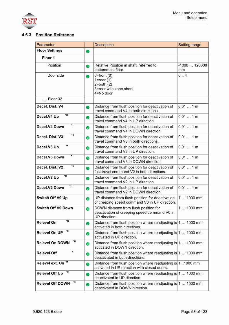
Menu and operation Setup menu
9.620.123-6.docx Page 58 of 123
4.6.3 Position Reference
Parameter Description Setting range Floor Settings ☻
Floor 1
Position ☻ Relative Position in shaft, referred to bottommost floor.
-1000 … 128000 mm
Door side ☻ 0=front (0) 1=rear (1) 2=both (2) 3=rear with zone sheet 4=No door
0 .. 4
…. Floor 32
Decel. Dist. V4 ☻ Distance from flush position for deactivation of travel command V4 in both directions.
0.01 … 1 m
Decel.V4 Up *H ☻ Distance from flush position for deactivation of travel command V4 in UP direction.
0.01 … 1 m
Decel.V4 Down *H ☻ Distance from flush position for deactivation of travel command V4 in DOWN direction.
0.01 … 1 m
Decel. Dist. V3 *S ☻ Distance from flush position for deactivation of travel command V3 in both directions.
0.01 … 1 m
Decel.V3 Up *H ☻ Distance from flush position for deactivation of travel command V3 in UP direction.
0.01 … 1 m
Decel.V3 Down *H ☻ Distance from flush position for deactivation of travel command V3 in DOWN direction.
0.01 … 1 m
Decel. Dist. V2 *S ☻ Distance from flush position for deactivation of fast travel command V2 in both directions.
0.01 … 1 m
Decel.V2 Up *H ☻ Distance from flush position for deactivation of travel command V2 in UP direction.
0.01 … 1 m
Decel.V2 Down *H ☻ Distance from flush position for deactivation of travel command V2 in DOWN direction.
0.01 … 1 m
Switch Off V0 Up ☻ UP distance from flush position for deactivation of creeping speed command V0 in UP direction.
1 … 1000 mm
Switch Off V0 Down ☻ DOWN distance from flush position for deactivation of creeping speed command V0 in UP direction.
1 … 1000 mm
Relevel On *S
☻ Distance from flush position where readjusting is activated in both directions.
1 … 1000 mm
Relevel On UP *H
☻ Distance from flush position where readjusting is activated in UP direction.
1 … 1000 mm
Relevel On DOWN *H
☻ Distance from flush position where readjusting is activated in DOWN direction.
1 … 1000 mm
Relevel Off *S
☻ Distance from flush position where readjusting is deactivated in both directions.
1 … 1000 mm
Relevel ext. On *H
☻ Distance from flush position where readjusting is activated in UP direction with closed doors.
1 ..1000 mm
Relevel Off Up *H
☻ Distance from flush position where readjusting is deactivated in UP direction.
1 … 1000 mm
Relevel Off DOWN *H
☻ Distance from flush position where readjusting is deactivated in DOWN direction.
1 … 1000 mm
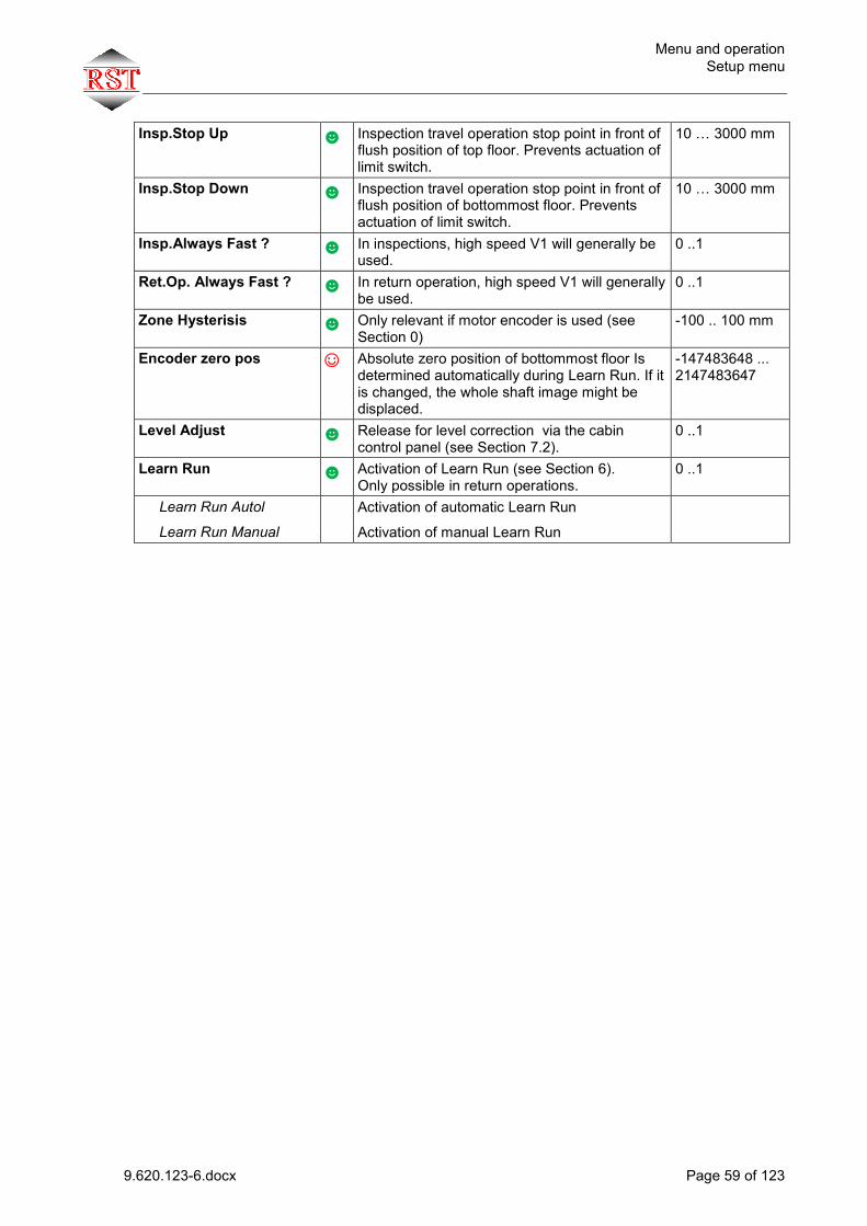
Menu and operation Setup menu
9.620.123-6.docx Page 59 of 123
Insp.Stop Up ☻ Inspection travel operation stop point in front of flush position of top floor. Prevents actuation of limit switch.
10 … 3000 mm
Insp.Stop Down ☻ Inspection travel operation stop point in front of flush position of bottommost floor. Prevents actuation of limit switch.
10 … 3000 mm
Insp.Always Fast ? ☻ In inspections, high speed V1 will generally be used.
0 ..1
Ret.Op. Always Fast ? ☻ In return operation, high speed V1 will generally be used.
0 ..1
Zone Hysterisis ☻ Only relevant if motor encoder is used (see Section 0)
-100 .. 100 mm
Encoder zero pos ☺ Absolute zero position of bottommost floor Is determined automatically during Learn Run. If it is changed, the whole shaft image might be displaced.
-147483648 ... 2147483647
Level Adjust ☻ Release for level correction via the cabin control panel (see Section 7.2).
0 ..1
Learn Run
☻ Activation of Learn Run (see Section 6). Only possible in return operations.
0 ..1
Learn Run Autol
Learn Run Manual Activation of automatic Learn Run
Activation of manual Learn Run

Menu and operation Setup menu
9.620.123-6.docx Page 60 of 123
4.6.4 Doors Attention: Different door-types front/back RST (eg. atomatic/manual) please contact RST !
Parameter Description Setting range Pre Opening Doors ☻ Distance from flush position for early door
opening. Cabin must be within the zone and the speed must be less than 0.3m/s. To deactivate set “0”.
0 .. 1000 mm (0 = OFF)
Doors Collective.? ☻ 0=selective: 1 button each for front and rear door side. Calls effective for the relevant door. 1=collective: 1 common button for front and rear door side. Calls effective for both doors.
0 .. 1
Lock+Bolt Magnet F+R? ☻ 1=Yes: Rear door provided with its own locking magnet.
0 .. 1
Separation Door? ☻ 1=Yes: The states of the separating door are evaluated
0 .. 1
Lock pause close ☻ Halt time before lock is engaged 500 .. 10000
Lock pause open ☻ Halt time before lock is opened 0 .. 10000
SluiceOperation? ☻ 0: OFF 1: Door front, than door rear 1: Door rear, than door front
0 .. 1
Entr.AreaMon.Time ☻ Time until the door has closed by approx. 80% after the start of the closing operation. After that, the input terminal will no longer be evaluated.
1 .. 100 s
Entr.AreaMon.Tmout ☻ If the signal is present at the input terminal for longer than this time, the terminal will no longer be evaluated (e.g. if there is an obstacle in front of the cabin door).
1 .. 3600 s
Door Para. Front ☻
Door Type ☻
AutoDoor with locking magnet AutoDoor without locking magnet Semiauto/without door
Automatic cabin door with locking magnet Automatic cabin door without locking magnet Semiautomatic door No cabin termination door
LR Test=>Start ☻ 0=OFF, 1=1door side, 2=2door sides 0 .. 2
LR Status=>Run ☻ 0=OFF, 1=1door side, 2=2door sides 0 .. 2
Light Ray w. Reset? ☻ 1=Yes: Use of light grid in combination with Reset button
0 .. 1
Door Time Car ☻ Open time of door when there are other inside calls.
1 .. 100 s
Door Time Landing ☻ Open time of door when there are other outside calls.
1 .. 100 s
Time Open no Call ☻ Open time of door when there are no calls. 1 .. 600 s
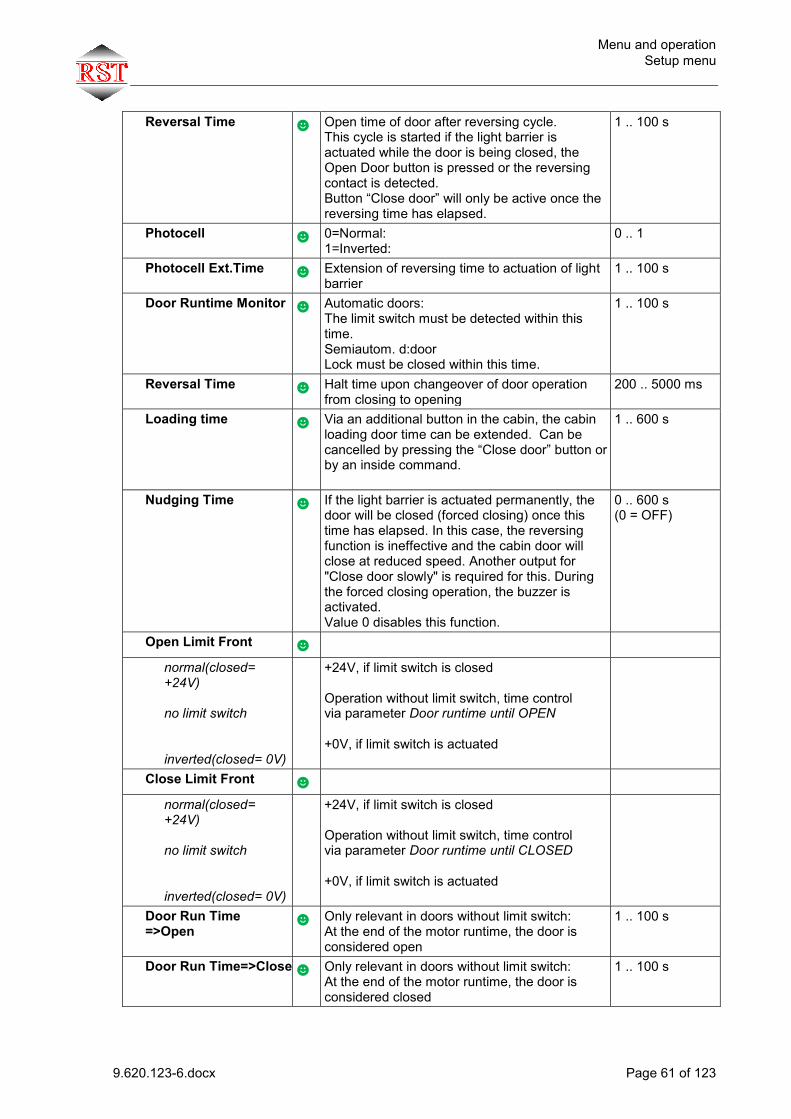
Menu and operation Setup menu
9.620.123-6.docx Page 61 of 123
Reversal Time ☻ Open time of door after reversing cycle. This cycle is started if the light barrier is actuated while the door is being closed, the Open Door button is pressed or the reversing contact is detected. Button “Close door” will only be active once the reversing time has elapsed.
1 .. 100 s
Photocell ☻ 0=Normal: 1=Inverted:
0 .. 1
Photocell Ext.Time ☻ Extension of reversing time to actuation of light barrier
1 .. 100 s
Door Runtime Monitor ☻ Automatic doors: The limit switch must be detected within this time. Semiautom. d:door Lock must be closed within this time.
1 .. 100 s
Reversal Time ☻ Halt time upon changeover of door operation from closing to opening
200 .. 5000 ms
Loading time ☻ Via an additional button in the cabin, the cabin loading door time can be extended. Can be cancelled by pressing the “Close door” button or by an inside command.
1 .. 600 s
Nudging Time ☻ If the light barrier is actuated permanently, the door will be closed (forced closing) once this time has elapsed. In this case, the reversing function is ineffective and the cabin door will close at reduced speed. Another output for "Close door slowly" is required for this. During the forced closing operation, the buzzer is activated. Value 0 disables this function.
0 .. 600 s (0 = OFF)
Open Limit Front ☻
normal(closed= +24V) no limit switch inverted(closed= 0V)
+24V, if limit switch is closed Operation without limit switch, time control via parameter Door runtime until OPEN +0V, if limit switch is actuated
Close Limit Front ☻
normal(closed= +24V) no limit switch inverted(closed= 0V)
+24V, if limit switch is closed Operation without limit switch, time control via parameter Door runtime until CLOSED +0V, if limit switch is actuated
Door Run Time =>Open
☻ Only relevant in doors without limit switch: At the end of the motor runtime, the door is considered open
1 .. 100 s
Door Run Time=>Close ☻ Only relevant in doors without limit switch: At the end of the motor runtime, the door is considered closed
1 .. 100 s
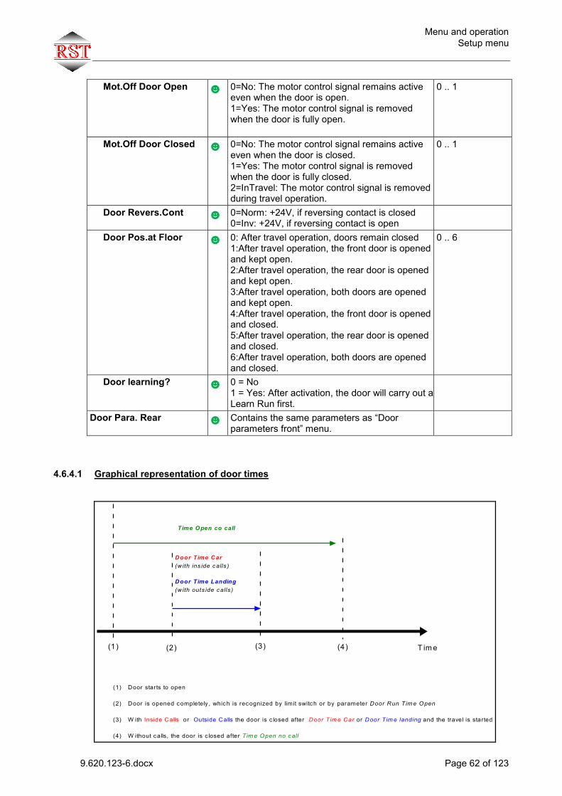
Menu and operation Setup menu
9.620.123-6.docx Page 62 of 123
Mot.Off Door Open ☻ 0=No: The motor control signal remains active even when the door is open. 1=Yes: The motor control signal is removed when the door is fully open.
0 .. 1
Mot.Off Door Closed ☻ 0=No: The motor control signal remains active even when the door is closed. 1=Yes: The motor control signal is removed when the door is fully closed. 2=InTravel: The motor control signal is removed during travel operation.
0 .. 1
Door Revers.Cont ☻ 0=Norm: +24V, if reversing contact is closed 0=Inv: +24V, if reversing contact is open
Door Pos.at Floor ☻ 0: After travel operation, doors remain closed 1:After travel operation, the front door is opened and kept open. 2:After travel operation, the rear door is opened and kept open. 3:After travel operation, both doors are opened and kept open. 4:After travel operation, the front door is opened and closed. 5:After travel operation, the rear door is opened and closed. 6:After travel operation, both doors are opened and closed.
0 .. 6
Door learning? ☻ 0 = No 1 = Yes: After activation, the door will carry out a Learn Run first.
Door Para. Rear ☻ Contains the same parameters as “Door parameters front” menu.
4.6.4.1 Graphical representation of door times
T im e(1) (2)
(1) Door starts to open
(2) Door is opened completely , which is recognized by limit switch or by parameter Door Run Tim e Open
(3) W ith Inside Calls or Outside Calls the door is c losed after Door Tim e Car or Door Tim e landing and the travel is started
(4) W ithout calls, the door is c losed after Tim e Open no call
Door Time Car(w ith ins ide calls )
Door Time Landing(w ith outs ide calls )
Time Open co call
(3) (4)

Menu and operation Setup menu
9.620.123-6.docx Page 63 of 123
4.6.5 Controller
Parameter Description Setting range Timer ☻ Weekly program with 1 switching point a day
Times ☻
Lock Debounce Time ☻ Time elapsing after closing of lock until lock input is valid.
10 .. 1000 ms
Start delay ☻ Delay time between closing of safety circuit and start of travel command execution
0.1 .. 10 s
Car Fan Run Time ☻ Delay of cabin fan after end of travel operation.
0 .. 10 s
Car Light Off Time ☻ Time after end of travel operation until cabin light is turned off
1 .. 600 s
Priority ☻
Car Priority Time ☻ Once inside priority is activated, it will remain active for the set time
0 .. 120 s
Land. Priority Time ☻ Once outside priority is activated, it will remain active for the set time
0 .. 120 s
Landing Priority ☻ 0=Hard: Priority is activated immediately - inside calls will be deleted. 1=Soft: Priority will only be activated once inside calls have been processed. 2=Soft+empty: Priority will only be activated once inside calls have been processed and the cabin is empty
0 .. 2
Car Call w. Prio.. ☻ 0=No: 1=Yes:
0 .. 1
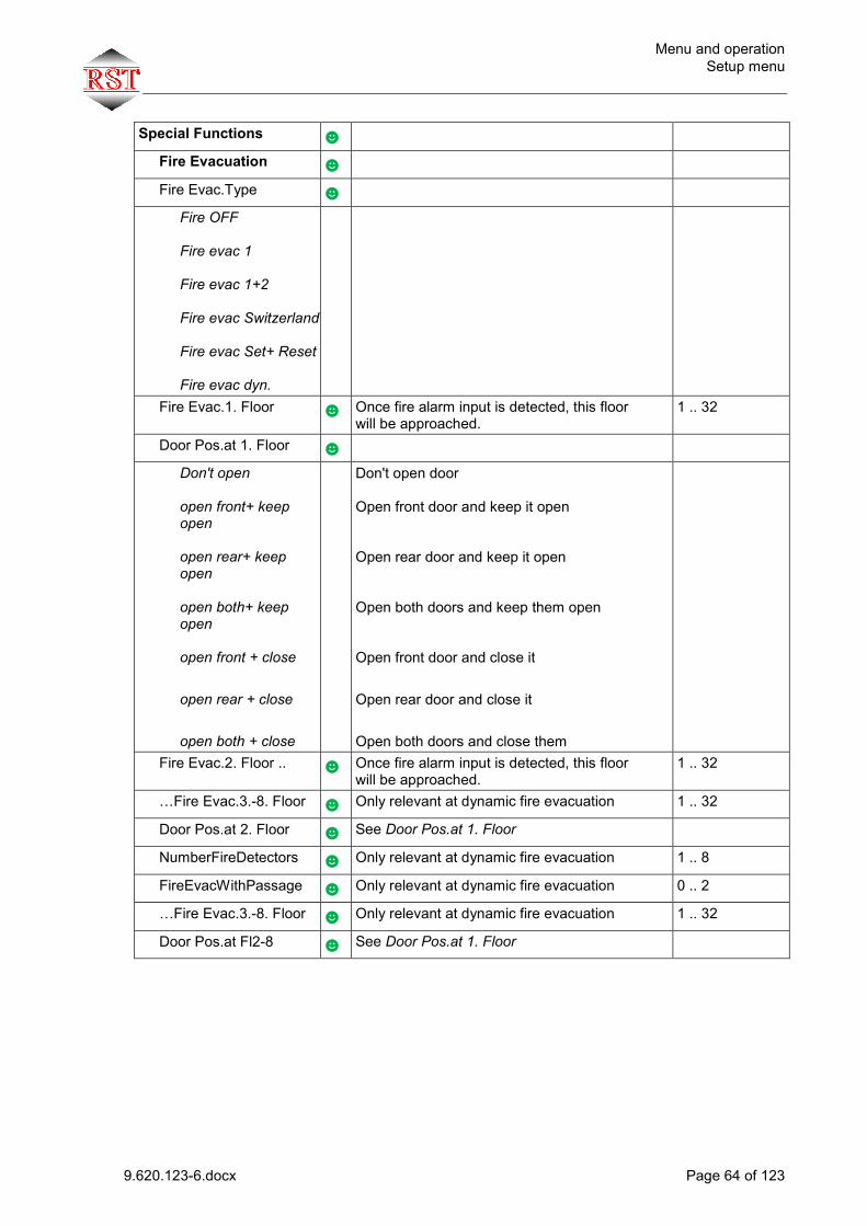
Menu and operation Setup menu
9.620.123-6.docx Page 64 of 123
Special Functions ☻
Fire Evacuation ☻
Fire Evac.Type ☻
Fire OFF Fire evac 1 Fire evac 1+2 Fire evac Switzerland Fire evac Set+ Reset Fire evac dyn.
Fire Evac.1. Floor ☻ Once fire alarm input is detected, this floor will be approached.
1 .. 32
Door Pos.at 1. Floor ☻
Don't open open front+ keep open open rear+ keep open open both+ keep open open front + close
open rear + close
open both + close
Don't open door Open front door and keep it open Open rear door and keep it open Open both doors and keep them open Open front door and close it
Open rear door and close it
Open both doors and close them
Fire Evac.2. Floor ..
☻ Once fire alarm input is detected, this floor will be approached.
1 .. 32
…Fire Evac.3.-8. Floor ☻ Only relevant at dynamic fire evacuation 1 .. 32
Door Pos.at 2. Floor ☻ See Door Pos.at 1. Floor
NumberFireDetectors ☻ Only relevant at dynamic fire evacuation 1 .. 8
FireEvacWithPassage ☻ Only relevant at dynamic fire evacuation 0 .. 2
…Fire Evac.3.-8. Floor ☻ Only relevant at dynamic fire evacuation 1 .. 32
Door Pos.at Fl2-8 ☻ See Door Pos.at 1. Floor
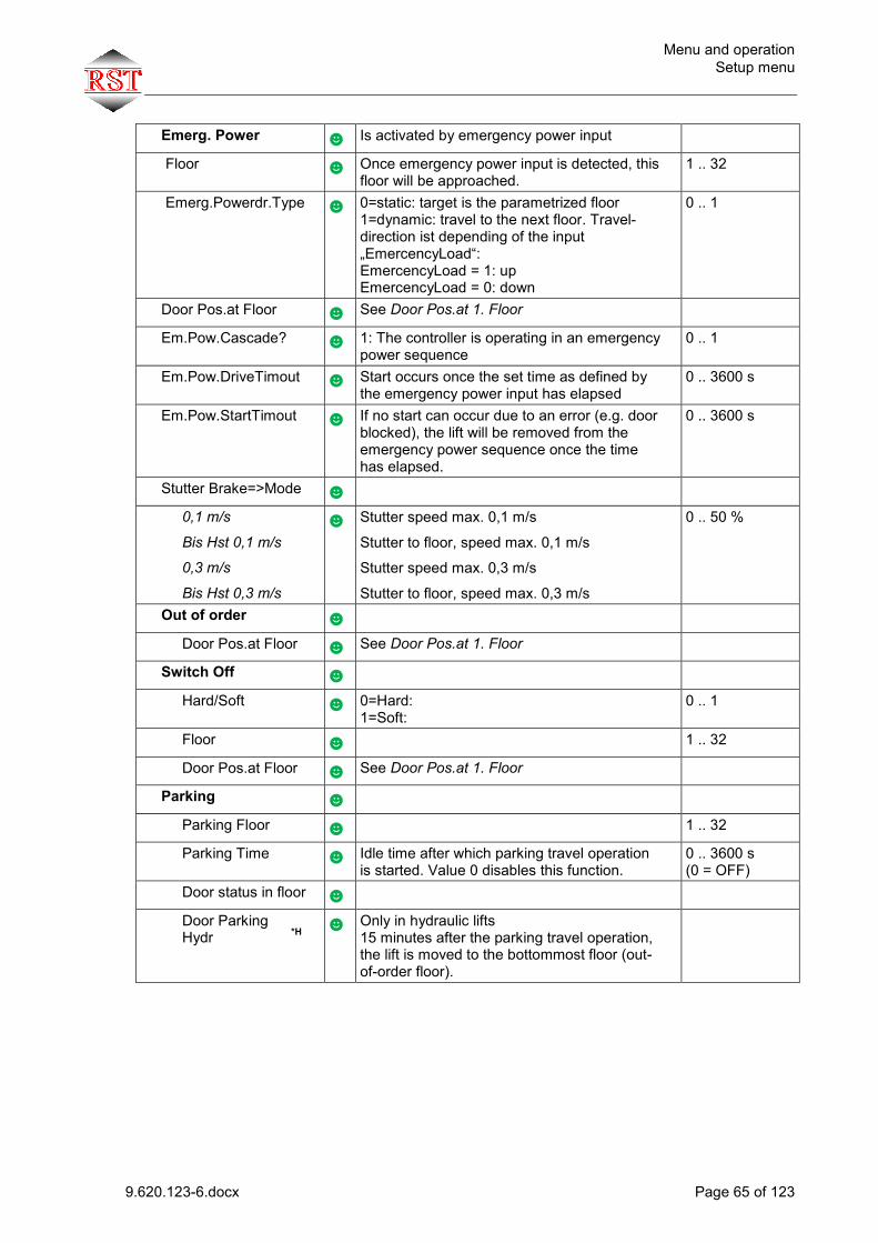
Menu and operation Setup menu
9.620.123-6.docx Page 65 of 123
Emerg. Power ☻ Is activated by emergency power input
Floor ☻ Once emergency power input is detected, this floor will be approached.
1 .. 32
Emerg.Powerdr.Type ☻ 0=static: target is the parametrized floor 1=dynamic: travel to the next floor. Travel-direction ist depending of the input „EmercencyLoad“: EmercencyLoad = 1: up EmercencyLoad = 0: down
0 .. 1
Door Pos.at Floor ☻ See Door Pos.at 1. Floor
Em.Pow.Cascade? ☻ 1: The controller is operating in an emergency power sequence
0 .. 1
Em.Pow.DriveTimout ☻ Start occurs once the set time as defined by the emergency power input has elapsed
0 .. 3600 s
Em.Pow.StartTimout ☻ If no start can occur due to an error (e.g. door blocked), the lift will be removed from the emergency power sequence once the time has elapsed.
0 .. 3600 s
Stutter Brake=>Mode ☻
0,1 m/s
Bis Hst 0,1 m/s
0,3 m/s
Bis Hst 0,3 m/s
☻ Stutter speed max. 0,1 m/s
Stutter to floor, speed max. 0,1 m/s
Stutter speed max. 0,3 m/s
Stutter to floor, speed max. 0,3 m/s
0 .. 50 %
Out of order ☻
Door Pos.at Floor ☻ See Door Pos.at 1. Floor
Switch Off ☻
Hard/Soft ☻ 0=Hard: 1=Soft:
0 .. 1
Floor ☻ 1 .. 32
Door Pos.at Floor ☻ See Door Pos.at 1. Floor
Parking ☻
Parking Floor ☻ 1 .. 32
Parking Time ☻ Idle time after which parking travel operation is started. Value 0 disables this function.
0 .. 3600 s (0 = OFF)
Door status in floor ☻
Door Parking Hydr *H
☻ Only in hydraulic lifts 15 minutes after the parking travel operation, the lift is moved to the bottommost floor (out-of-order floor).
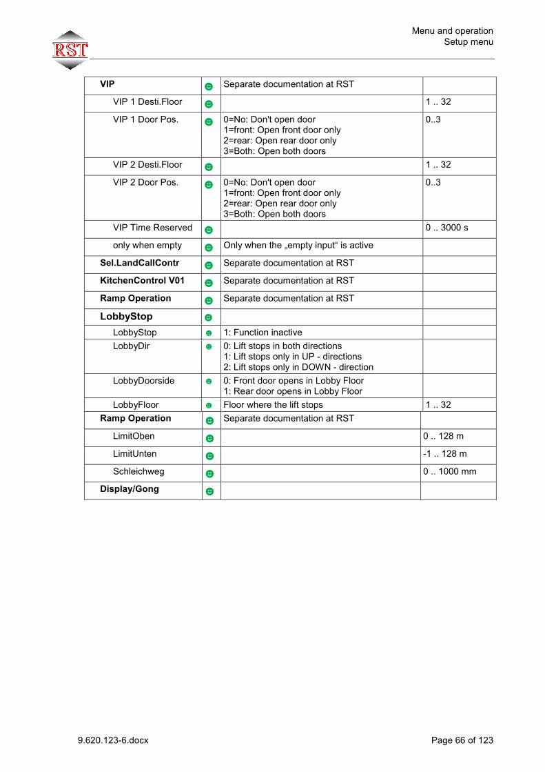
Menu and operation Setup menu
9.620.123-6.docx Page 66 of 123
VIP ☻ Separate documentation at RST
VIP 1 Desti.Floor ☻ 1 .. 32
VIP 1 Door Pos. ☻ 0=No: Don't open door 1=front: Open front door only 2=rear: Open rear door only 3=Both: Open both doors
0..3
VIP 2 Desti.Floor ☻ 1 .. 32
VIP 2 Door Pos. ☻ 0=No: Don't open door 1=front: Open front door only 2=rear: Open rear door only 3=Both: Open both doors
0..3
VIP Time Reserved ☻ 0 .. 3000 s
only when empty ☻ Only when the „empty input“ is active
Sel.LandCallContr ☻ Separate documentation at RST
KitchenControl V01 ☻ Separate documentation at RST
Ramp Operation ☻ Separate documentation at RST
LobbyStop ☻
LobbyStop ☻ 1: Function inactive LobbyDir ☻ 0: Lift stops in both directions
1: Lift stops only in UP - directions 2: Lift stops only in DOWN - direction
LobbyDoorside ☻ 0: Front door opens in Lobby Floor 1: Rear door opens in Lobby Floor
LobbyFloor ☻ Floor where the lift stops 1 .. 32 Ramp Operation ☻ Separate documentation at RST
LimitOben ☻ 0 .. 128 m
LimitUnten ☻ -1 .. 128 m
Schleichweg ☻ 0 .. 1000 mm
Display/Gong ☻

Menu and operation Setup menu
9.620.123-6.docx Page 67 of 123
Pos.Indicator ☻
Floor Text ☻ Only for EAM from RST. Texts for each floor.
Language ☻ Only for EAM from RST. Language selection for floor texts.
Displaymode ☻ Only for EAM from RST. Selection of representation
Floor Changes ☻ Only for EAM from RST. 0: Hard transition 1: Soft transition. Floor value scrolled in travel direction 2: Soft transition. Floor value scrolled against travel direction
Scroll Speed ☻ Only for EAM from RST. Definition of run-through speed of arrows and texts
Change at Target? ☻ Only for EAM from RST. 0: Display switches in the middle between 2 floors. 1: Display switches when destination zone is reached.
Disp.SpecDrive? ☻ Only for EAM from RST. 0: Special travel operations are not displayed 1: Special travel operations are displayed via scrolling texts
Landing Disp.Binary? ☻ For parallel-controlled floor displays. 0: Output Gray-encoded 1: Output binary-encoded
Cab.Target.Land.Dist ☻ The distance to the the target floor in which the floor position will be displayed permanently
1 .. 10000 mm
Gong-Functions ☻
Gong.Dist.to Floor ☻ The distance to the the target floor at which the gong signal will be activated
0 .. 10000 mm
Gong at Land.? ☻ Gong signal at floor will be activated with hall call
0 .. 1
Blinking Approach? ☻ 0=No: No flashing. 1=Yes: Flashing when landing
0 .. 1
Range Cab.Pos. ☺ Range in which the signal Cabin Position is output at the floors
20 .. 100000 mm
Lock w. Inv. Error ☻ 0=No: After inverter faults, the controller tries to restart 1=Yes: Controller will be disabled after a inverter fault
0 .. 1
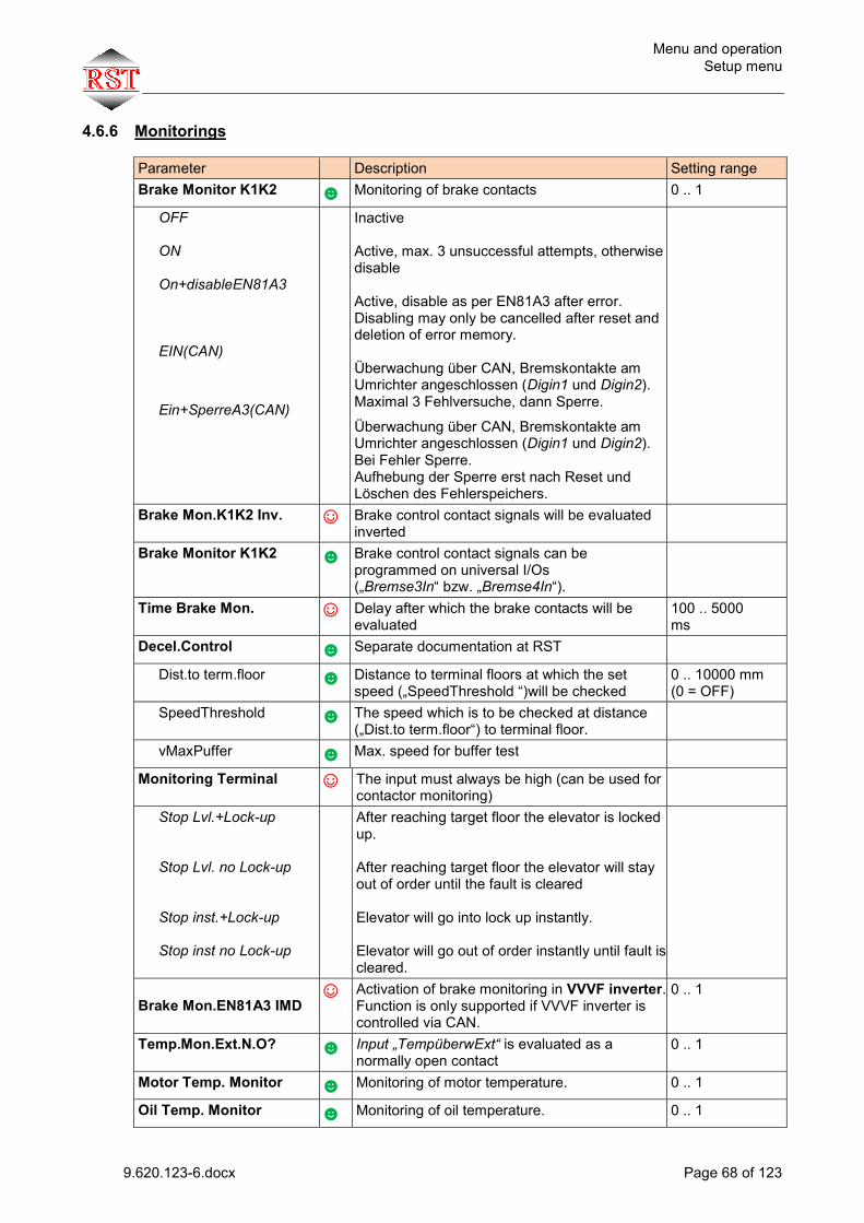
Menu and operation Setup menu
9.620.123-6.docx Page 68 of 123
4.6.6 Monitorings
Parameter Description Setting range Brake Monitor K1K2 ☻ Monitoring of brake contacts 0 .. 1
OFF
ON
On+disableEN81A3
EIN(CAN)
Ein+SperreA3(CAN)
Inactive Active, max. 3 unsuccessful attempts, otherwise disable Active, disable as per EN81A3 after error. Disabling may only be cancelled after reset and deletion of error memory. Überwachung über CAN, Bremskontakte am Umrichter angeschlossen (Digin1 und Digin2). Maximal 3 Fehlversuche, dann Sperre.
Überwachung über CAN, Bremskontakte am Umrichter angeschlossen (Digin1 und Digin2). Bei Fehler Sperre. Aufhebung der Sperre erst nach Reset und Löschen des Fehlerspeichers.
Brake Mon.K1K2 Inv. ☺ Brake control contact signals will be evaluated inverted
Brake Monitor K1K2 ☻ Brake control contact signals can be programmed on universal I/Os („Bremse3In“ bzw. „Bremse4In“).
Time Brake Mon. ☺ Delay after which the brake contacts will be evaluated
100 .. 5000 ms
Decel.Control ☻ Separate documentation at RST
Dist.to term.floor
☻ Distance to terminal floors at which the set speed („SpeedThreshold “)will be checked
0 .. 10000 mm (0 = OFF)
SpeedThreshold ☻ The speed which is to be checked at distance („Dist.to term.floor“) to terminal floor.
vMaxPuffer ☻ Max. speed for buffer test
Monitoring Terminal ☺ The input must always be high (can be used for contactor monitoring)
Stop Lvl.+Lock-up Stop Lvl. no Lock-up Stop inst.+Lock-up Stop inst no Lock-up
After reaching target floor the elevator is locked up.
After reaching target floor the elevator will stay out of order until the fault is cleared Elevator will go into lock up instantly. Elevator will go out of order instantly until fault is cleared.
Brake Mon.EN81A3 IMD
☺ Activation of brake monitoring in VVVF inverter. Function is only supported if VVVF inverter is controlled via CAN.
0 .. 1
Temp.Mon.Ext.N.O? ☻ Input „TempüberwExt“ is evaluated as a normally open contact
0 .. 1
Motor Temp. Monitor ☻ Monitoring of motor temperature. 0 .. 1
Oil Temp. Monitor ☻ Monitoring of oil temperature. 0 .. 1

Menu and operation Setup menu
9.620.123-6.docx Page 69 of 123
Run Time Monitor ☻ Monitoring of travel time. Zone signal must be received within the set time. Value 0 disables this function.
0 .. 45 s (0 = OFF)
Car Start Monitor ☻ Monitor checks if the cabin is moving upon start (threshold 0.01 m/s). on. Value 0 disables this function.
0 .. 20 s (0 = OFF)
Lock Monitor ☻ Maximum wait time when lock is closed 0.1 .. 10 s
Max. temperature ☺ Max. electrical cabinet temperature When exceeded, the lift will move to Out-of-Order stop.
10 .. 100 °C
Min. temperature ☺ Min. electrical cabinet temperature If temperature is lower, the lift will move to Out-of-Order stop.
-10 .. 100 °C
Temperature Out 1 ☻ Switching threshold for temperature output1 10 .. 100 °C
Temperature Out 2 ☻ Switching threshold for temperature output2 10 .. 100 °C
Photocell Max.Time. ☺ Max. time of light barrier interruption. If higher, display “Out of Order”. Value 0 disables the monitoring function.
0 .. 600 s (0 = OFF)
Level Monitor ☺ If, after a normal travel operation (no inspection or return operation), the stop inaccuracy is greater than the set value, an entry will be made in the error memory. Value 0 disables the monitoring function.
0 .. 100 mm (0 = OFF)
VMaxInspection ☻ Maximum permitted inspection-speed 0,3 .. 0,8 m/s
DirMonitCabine ☺ Maximum distance allowed for wrong direction movement
5 .. 100 mm
No Move during run ☺ Maximum time allowed for no movement 1000 .. 10000 ms
Rope Slip ☺ Cable slip monitor, enter max. slip. Value 0 disables the monitoring function. Only possible with CANDrive interface to VVVF inverter
0 .. 500 mm
Car Light Monitor ☻
Light Mon.Err.Time ☻ Time delay before cabin light- fault
Activate ☻ Cabin lighting is monitored by measuring the lighting current. Here, you can set the threshold for a failure of the cabin lighting. Value 0 disables the monitoring function.
0 .. 100 % (0 = OFF)
Car Light Measure. ☻ Display of currently measured cabin light current.
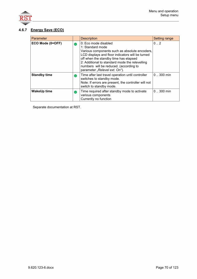
Menu and operation Setup menu
9.620.123-6.docx Page 70 of 123
4.6.7 Energy Save (ECO)
Parameter Description Setting range ECO Mode (0=OFF) ☻ 0: Eco mode disabled
1: Standard mode Various components such as absolute encoders, LCD displays and floor indicators will be turned off when the standby time has elapsed 2: Additional to standard mode the relevelling numbers will be reduced. (according to parameter „Relevel ext. On“).
0 .. 2
Standby time ☻ Time after last travel operation until controller switches to standby mode. Note: If errors are present, the controller will not switch to standby mode.
0 .. 300 min
WakeUp time ☻ Time required after standby mode to activate various components Currently no function
0 .. 300 min
Separate documentation at RST.
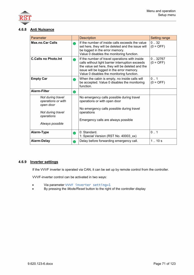
Menu and operation Setup menu
9.620.123-6.docx Page 71 of 123
4.6.8 Anti Nuisance
Parameter Description Setting range Max.no.Car Calls ☻ If the number of inside calls exceeds the value
set here, they will be deleted and the issue will be logged in the error memory. Value 0 disables the monitoring function.
0 .. 32 (0 = OFF)
C.Calls no Photo.Int ☻ If the number of travel operations with inside calls without light barrier interruption exceeds the value set here, they will be deleted and the issue will be logged in the error memory. Value 0 disables the monitoring function.
0 .. 32767 (0 = OFF)
Empty Car ☻ When the cabin is empty, no inside calls will be accepted. Value 0 disables the monitoring function.
0 .. 1 (0 = OFF)
Alarm-Filter ☻
Not during travel operations or with open door Not during travel operations Always possible
No emergency calls possible during travel operations or with open door No emergency calls possible during travel operations Emergency calls are always possible
Alarm-Type ☻ 0: Standard. 1: Special Version (RST No. 40003_xx)
0 .. 1
Alarm-Delay ☻ Delay before forwarding emergency call. 1 .. 10 s
4.6.9 Inverter settings
If the VVVF inverter is operated via CAN, it can be set up by remote control from the controller. VVVF-inverter control can be activated in two ways:
Via parameter VVVF inverter setting=1 By pressing the Mode/Reset button to the right of the controller display
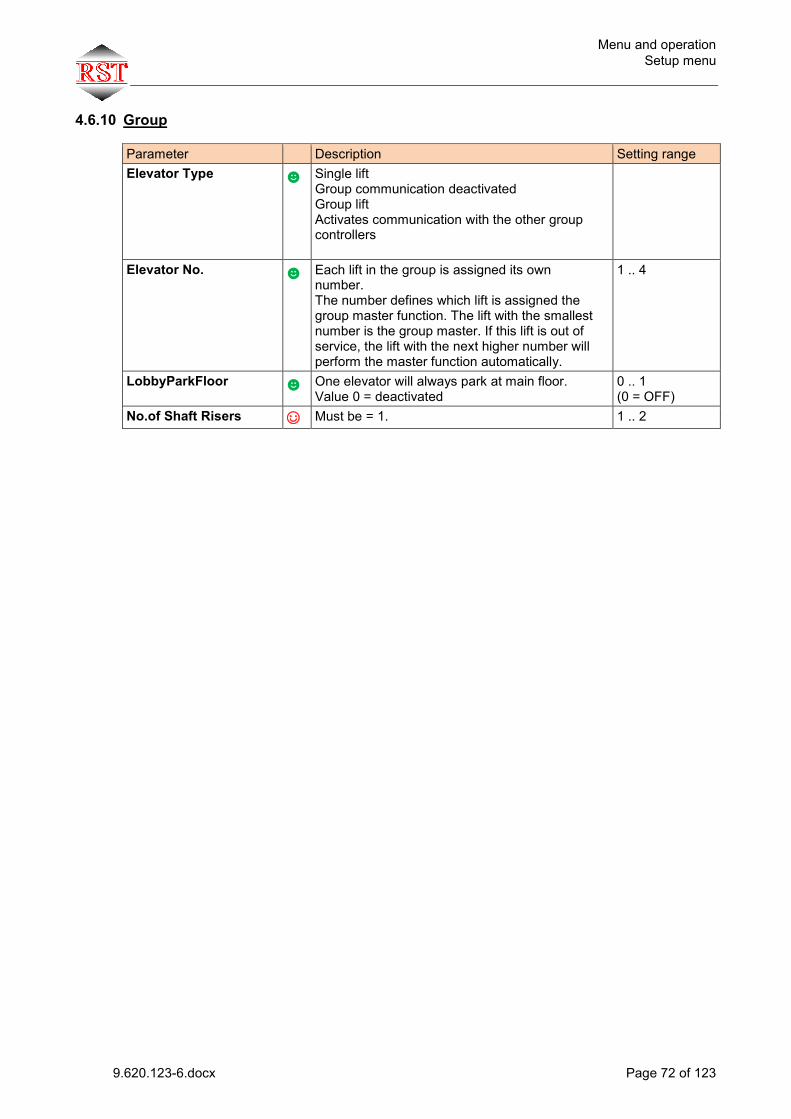
Menu and operation Setup menu
9.620.123-6.docx Page 72 of 123
4.6.10 Group
Parameter Description Setting range Elevator Type ☻ Single lift
Group communication deactivated Group lift Activates communication with the other group controllers
Elevator No. ☻ Each lift in the group is assigned its own number. The number defines which lift is assigned the group master function. The lift with the smallest number is the group master. If this lift is out of service, the lift with the next higher number will perform the master function automatically.
1 .. 4
LobbyParkFloor ☻ One elevator will always park at main floor. Value 0 = deactivated
0 .. 1 (0 = OFF)
No.of Shaft Risers ☺ Must be = 1. 1 .. 2
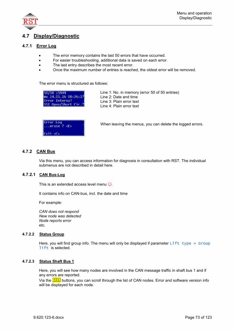
Menu and operation Display/Diagnostic
9.620.123-6.docx Page 73 of 123
4.7 Display/Diagnostic
4.7.1 Error Log
The error memory contains the last 50 errors that have occurred. For easier troubleshooting, additional data is saved on each error. The last entry describes the most recent error. Once the maximum number of entries is reached, the oldest error will be removed. The error menu is structured as follows:
Line 1: No. in memory (error 50 of 50 entries) Line 2: Date and time Line 3: Plain error text Line 4: Plain error text
When leaving the menus, you can delete the logged errors.
4.7.2 CAN Bus
Via this menu, you can access information for diagnosis in consultation with RST. The individual submenus are not described in detail here.
4.7.2.1 CAN Bus-Log
This is an extended access level menu ☺.
It contains info on CAN-bus, incl. the date and time For example: CAN does not respond New node was detected Node reports error etc.
4.7.2.2 Status Group
Here, you will find group info. The menu will only be displayed if parameter Lift type = Group lift is selected.
4.7.2.3 Status Shaft Bus 1
Here, you will see how many nodes are involved in the CAN message traffic in shaft bus 1 and if any errors are reported. Via the buttons, you can scroll through the list of CAN nodes. Error and software version info will be displayed for each node.
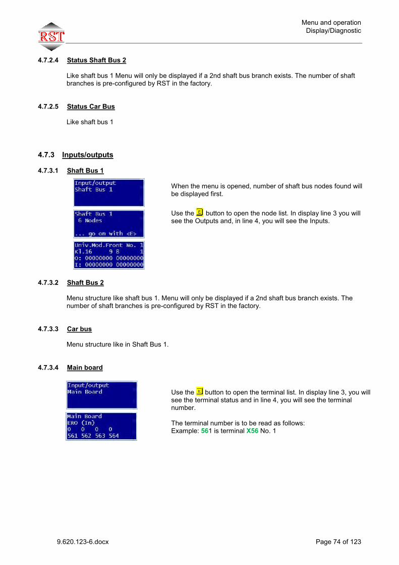
Menu and operation Display/Diagnostic
9.620.123-6.docx Page 74 of 123
4.7.2.4 Status Shaft Bus 2
Like shaft bus 1 Menu will only be displayed if a 2nd shaft bus branch exists. The number of shaft branches is pre-configured by RST in the factory.
4.7.2.5 Status Car Bus
Like shaft bus 1
4.7.3 Inputs/outputs
4.7.3.1 Shaft Bus 1
When the menu is opened, number of shaft bus nodes found will be displayed first.
Use the button to open the node list. In display line 3 you will see the Outputs and, in line 4, you will see the Inputs.
4.7.3.2 Shaft Bus 2
Menu structure like shaft bus 1. Menu will only be displayed if a 2nd shaft bus branch exists. The number of shaft branches is pre-configured by RST in the factory.
4.7.3.3 Car bus Menu structure like in Shaft Bus 1.
4.7.3.4 Main board
Use the button to open the terminal list. In display line 3, you will see the terminal status and in line 4, you will see the terminal number. The terminal number is to be read as follows: Example: 561 is terminal X56 No. 1

Menu and operation Display/Diagnostic
9.620.123-6.docx Page 75 of 123
4.7.4 Actual Values
Display value Description Unit Rope Slip ☻
Factor mm->Incr. ☻ Conversion factor shaft position VVVF inverter increments
Current slip ☻ Measured cable slip of last travel operation
Max. slip ☻ Measured maximum cable slip of all travel operations since last Power-On
Car Position ☻ Current cabin position. mm
CarSpeedDecel.Point ☻ Cabin speed at last control point mm/s
Car Speed MAX ☻ Maximum cabin speed of last travel operation. mm/s
Car Accel. MAX ☻ Maximum cabin acceleration of last travel operation.
mm/s2
Temperature ☻ Current ambient temperature °C
Min>AbsPos>Max ☺ Counter of position values outside of shaft limits (EMC issues, encoder defects)
SSI-ErrEDCRL ☺ SSI error register (EMC issues, encoder defect)
PosDelta > Max ☺ Counter of events with implausible position changes (EMC issues, encoder defect)
CorrectionValZbl ☺ With motor encoder: current correction value at zone sheet
CorrectionValZbl MAX ☺ With motor encoder: Greatest correction value since Power-On at zone sheet

Menu and operation Display/Diagnostic
9.620.123-6.docx Page 76 of 123
4.7.5 Statistics
Display value Description Unit Absolute Counters ☻ Counter since commissioning of IMC-2
Run Counter ☻
Door Cycles Front ☻
Door Cycles Rear ☻
Active Hours ☻
Relative Counters ☻ Counter readings since last deletion
Run Counter ☻
Door Cycles Front ☻
Door Cycles Rear ☻
Active Hours ☻
Count Till Service ☻ Counter readings until next service
Run Counter ☻
Door Cycles Front ☻
Door Cycles Rear ☻
Active Hours ☻
Call Statistics ☻ Calls of individual floors/door sides
4.7.6 Actual Calls
Display value Description Unit Inside calls+outside calls ☻ Display of current calls
4.7.7 Software version
Display value Description Unit Software version ☻ Number, date
Bootloader version ☻ Number
4.7.8 Remote Access
Display value Description Unit Status ☻ Status of the GSM-Modem
LastRemoteInq ☻ Elapsed time since the last query
ConnectAttempts ☻ Number of connection attempts since reset
Signal Strength ☻ GSM signal strength 10 .. 30 = ok

Menu and operation System
9.620.123-6.docx Page 77 of 123
4.8 System
4.8.1 Inverter Control
Parameter Description Setting range Terminals ☻ The VVVF inverter is actuated via terminals
CANDriveVelocity ☻ The VVVF inverter is actuated via CAN bus Travel mode is like in actuation via terminals.
CANDrivePosition ☻ The VVVF inverter is actuated via CAN bus The VVVF inverter evaluates the position data from the controller and determines time-optimized travel profiles with direct landing.
4.8.2 Language Change the language.
4.8.3 Time/Date Display of current time and date.
4.8.4 Set Time/Date
Parameter Description Setting range Day ☻ 1 .. 31
Weekday (Su=1) ☻ 1 ..7
Month ☻ 1 ..12
Year (20xx) ☻ Example: 2013 -> Enter 13 11 .. 50
Hours ☻ 0 .. 23
Minutes ☻ 0 .. 59
Save Data? <E> ☻ Save entries
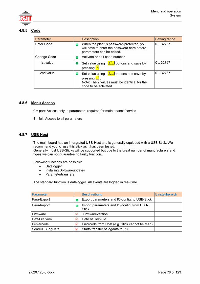
Menu and operation System
9.620.123-6.docx Page 78 of 123
4.8.5 Code
Parameter Description Setting range Enter Code ☻ When the plant is password-protected, you
will have to enter the password here before parameters can be edited.
0 .. 32767
Change Code ☻ Activate or edit code number
1st value ☻ Set value using buttons and save by pressing .
0 .. 32767
2nd value ☻ Set value using buttons and save by pressing . Note: The 2 values must be identical for the code to be activated.
0 .. 32767
4.8.6 Menu Access
0 = part: Access only to parameters required for maintenance/service 1 = full: Access to all parameters
4.8.7 USB Host
The main board has an intergrated USB-Host and is generally equipped with a USB Stick. We recommend you to use this stick as it has been tested. Generally most USB-Sticks will be supported but due to the great number of manufacturers and types we can not guarantee no faulty function. Following functions are possible:
Datalogger Installing Softwareupdates Parametertransfers
The standard function is datalogger. All events are logged in real-time.
Parameter Beschreibung Einstellbereich Para-Export ☻ Export parameters and IO-config. to USB-Stick
Para-Import ☻ Import parameters and IO-config. from USB-Stick
Firmware ☺ Firmwareversion Hex-File vom ☺ Date of Hex-File Fehlercode ☺ Errorcode from Host (e.g. Stick cannot be read) SendUSBLogData ☺ Starts transfer of logdata to PC

Menu and operation System
9.620.123-6.docx Page 79 of 123
4.8.8 Uploading software-Updates via integrated Flash Loader
Software updates should only be made in consultation with RST ! Via the integrated Flash Loader, you can upload software updates from a USB stick or PC. The Loader can only be activated if no travel operation is being executed and if inspection or return mode is on.
Note ! The programme in the Flash Memory will be deleted by this procedure. Note that the controller should not be turned off during the programming operation which will take some 2 minutes ! At the end of the update, the controller will execute a system reset. After that it is ready for operation.
4.8.8.1 Flashing from USB Stick The easiest way is flashing from a USB stick. Once a USB stick containing the “18080xxx.hex” programming file, the following message will be displayed for 10 s :
After confirmation (press button), the following prompt will be displayed. d Before the update process can be started, inspection or return mode must be activated.
When you take the stick out and plug it in again, the message will be displayed again.
4.8.8.2 Flashing from PC For further informations please contact RST.

Menu and operation Service
9.620.123-6.docx Page 80 of 123
4.9 Service
4.9.1 Calls
Parameter Description Setting range Random Calls ☻
Activate ☻ 1=On: Activation of automatic call generation 0 ..1
Call no. (act) ☻ Number of calls to be made automatically. In accidental mode, inside calls are generated.
0 .. 10000
Run Interval ☻ Time to wait after end of travel operation until making a new call.
0 .. 32767 s
Run Top/Bottom ☻ 1=Yes: Only calls to the end floors are made 0 .. 1
Disable Car Call F ☻ Disable inside calls, front door side, certain floors (see Section 4.9.1.3).
Disable Land.Call F ☻ Disable inside calls, rear door side, certain floors (see Section 4.9.1.3).
Disable Car Call R ☻ Disable outside calls, front door side, certain floors (see Section 4.9.1.3).
Disable Land. Call R ☻ Disable outside calls, rear door side, certain floors (see Section 4.9.1.3).
4.9.1.1 Manual calls via flip switch IMC-2
Actuate for a short time for call to next floor, travel direction corresponds to direction of actuation. Actuate for a long time for call to end floor, travel direction corresponds to direction of actuation.
4.9.1.2 Manual calls via keyboard and menu of IMC-2
In standard menu, press or for more than 0.5 s to activate the Calls menu.
The Calls menu will be displayed.
Use buttons to select the floor. It will be displayed in the first line of the display in square brackets.
Press button to make the call to the selected floor.
Note: The menu can also be used for displaying current calls.
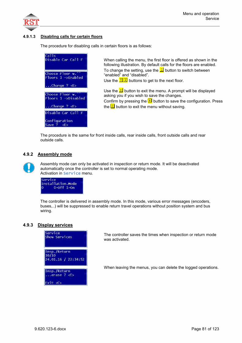
Menu and operation Service
9.620.123-6.docx Page 81 of 123
4.9.1.3 Disabling calls for certain floors
The procedure for disabling calls in certain floors is as follows:
When calling the menu, the first floor is offered as shown in the following illustration. By default calls for the floors are enabled. To change the setting, use the button to switch between “enabled” and “disabled”. Use the buttons to get to the next floor.
Use the button to exit the menu. A prompt will be displayed asking you if you wish to save the changes. Confirm by pressing the button to save the configuration. Press the button to exit the menu without saving.
The procedure is the same for front inside calls, rear inside calls, front outside calls and rear outside calls.
4.9.2 Assembly mode
Assembly mode can only be activated in inspection or return mode. It will be deactivated automatically once the controller is set to normal operating mode. Activation in Service menu. The controller is delivered in assembly mode. In this mode, various error messages (encoders, buses,..) will be suppressed to enable return travel operations without position system and bus wiring.
4.9.3 Display services
The controller saves the times when inspection or return mode was activated.
When leaving the menus, you can delete the logged operations.

Menu and operation Service
9.620.123-6.docx Page 82 of 123
4.9.4 TÜV / Test
Parameter Description Setting range Run Time Min. ☻ The runtime monitoring limit is reduced to 2 s
for one travel operation. In this way you can cause an intentional runtime error. After the travel operation, the value is set to 0 to disable this function.
0 .. 1
Top/Bott.Limit Test ☻ For the test, please move to an end floor. Creeping speed setting for the VVVF inverter will remain active even though the flush position is reached until the limit switch is reached. After the travel operation, the value is set to 0 to disable this function.
0 .. 1
Buffer-Test ERO ☻ In this mode ERO speed will be set to V4. Makes it possible to hit the buffer at max. speed.. Will be deactived automatically after one run.
0 .. 1
Overload OFF ☻ Die response to a cabin overload signal is suppressed for one travel operation. In this way, the travel operation can be executed even if the cabin is overloaded. After the travel operation, the value is set to 0 to disable this function.
0 .. 1
EN81-A3 Test Run ☻ Execution of test travel operation in order to test EN81-A3 functionality (see Section 0)
0 .. 1
N No Lockup SC ☻ No disable function in case of passive interruption of safety circuit for the time set (e.g. during TÜV inspection)
0 .. 60 min
Emerg.stop-Test ☻ This function will help to termin the mounting distance of the terminal speed control limit. An emergency stop can be initiated with the E-key during run The following will be displayed: • Total distance to standstill • Distance until the speed is below vMaxPuffer.
0 .. 1
4.9.5 Calibration of Inverter When function is active, the controller accepts changed VVVF inverter feedback (on main contactors and brake) for one travel operation. After the travel operation, the parameter will be reset automatically.

Menu and operation Service
9.620.123-6.docx Page 83 of 123
4.9.6 Service Interval
Parameter Description Setting range Runs Till Service ☻ If value is 0, the parameter is ignored for
determination of next service/maintenance. 0 ..20000000
Door Cycles Front ☻ If value is 0, the parameter is ignored for determination of next service/maintenance.
0 ..20000000
Door Cycles Rear ☻ If value is 0, the parameter is ignored for determination of next service/maintenance.
0 ..20000000
Active Hours ☻ If value is 0, the parameter is ignored for determination of next service/maintenance.
0 ..20000000
Set interval ☻ Use the button to include the counter values above in the general counter readings for the next service. Generally, a service message will be displayed once any of the counters has reached the service limit.
4.9.7 Erase Rel. Counter Here, you can delete the relative counters (see Section 0). To do this, confirm the prompt by pressing the button.
4.9.8 Monitoring
Parameter Description Setting range Remote Access ☻ 0: off
1: only at return operation 2: always 3: not when car priority is active
0 .. 3
Provider/Modemtyp ☻ Info is required for Internet access
AB-Nummer ☻ Required for lift assignment
SIM-Nummer ☻ Required for access to the system

Menu and operation Programmable I/0 functions
9.620.123-6.docx Page 84 of 123
4.10 Programmable I/0 functions
4.10.1 General The universal input/output terminals of the controller can be programmed very flexibly in the whole control system. Programming is done directly in plain text. You will find the terminal configuration menu in Settings – Unit – Term. Settings I/O The following distinction is made: IMC-2 main board Car Bus Shaft Bus 1 Shaft Bus 2
4.10.2 Programming Generally, the I/O terminals found in the menu are displayed. Example: At Car bus node no. 1, an I/O terminal is to be programmed with the function Arriving bell up on the front door side for Floor 1. To do this, switch to the I/O configuration menu first.
After pressing the button, the car bus menu will be displayed. Using the buttons you can select the other components (shaft bus, main board). After pressing the button, the first bus module found will be displayed. Use the buttons to scroll through all modules found. Use the button to start edit mode, the first terminal will be flashing. Use the buttons to select the required terminal of the module. Terminals marked with “+” are already assigned a function. Free terminals are marked with “-” . Use the button to start the function selection. Use the buttons to select the required function. The terminal functions are displayed in alphabetical order. Use the button to go to the next selection option. In the case of terminal functions without reference to floors or door sides, these selection options are not available, as shown in the left example.
Position reference systems SSI absolute encoder
9.620.123-6.docx Page 85 of 123
5 Position reference systems IMC-2 supports the following shaft copying systems:
5.1 SSI absolute encoder Connected to IMC-2 main board. A Wachendorff encoder type WDGA58B-10-1213 must be used. After Supply Power Off and On, the controller knows the position instantly. No search travel operation will take place.
5.2 ELGO LIMAX with SSI interface Connected to hand-held terminal. Position values are transmitted via CAN bus. After Supply Power Off and On, the controller knows the position instantly. No search travel operation will take place.
5.3 Shaft incremental encoder 1024 Pulses HTL +15.. +24V Connected to IMC-2 main board. A pre-limit switch must be installed at the bottom of the shaft. The controller will use it after Supply Power Off and On to identify the position of the bottommost floor.
5.4 Motor incremental encoder 1024 Pulses HTL +15.. +24V Connected to IMC-2 main board. A pre-limit switch must be installed at the bottom of the shaft. The controller will use it after Supply Power Off and On to identify the position of the bottommost floor. The motor/shaft pulse translation is performed during the Learn Run. Re-synchronization of the position (cable slip compensation) is done automatically at the zone sheets during the travel operation. The pre-limit switch is active-low, i.e. Level 0 means switch = ON !

Learn Run General
9.620.123-6.docx Page 86 of 123
6 Learn Run
6.1 General Before starting a teaching travel operation, you will have to deactivate installation mode! Deactivation in Service menu. You can perform automatic or manual teaching travel operations (in return mode).
During the teaching travel operation, the controller will determine the flush position (middle of zone sheet) and the door sides of the individual floors automatically. The detection is done based on the zone signals. For this reason, a zone sheet must be installed in each floor. In addition, it must be checked if the number of floors is set correctly (Menu Settings-Unit-Number of Floors). If an incremental encoder is used for shaft copying, it will be checked before starting the Learn Run if the pre-limit switch is installed. It must be installed in the bottom floor. If it is not installed, the relevant message will be displayed. The pre-limit switch is active-low, i.e. Level 0 means switch = ON. If a motor encoder is used, you will have to determine the transmission ratio between motor pulses and cabin movement first. To that end a zone sheet must be passed in return mode. This is done via an interactive menu. The procedure is self-explanatory and not described in detail for this reason.
6.2 Execution In return mode, move the cabin to the bottommost floor, ensure that it is within the zone sheet area.
Switch to menu Settings – Position Reference – Learn Run Start the function by pressing the button. The following warning will be displayed. Confirm it by pressing the button... Now, you can choose either an automatic or a manual Learn Run. Choose the relevant menu or .. and start teaching mode by pressing the button again. After deactivation of return mode, the Learn Run will start now in automatic mode. In manual mode, please move up using the return control …
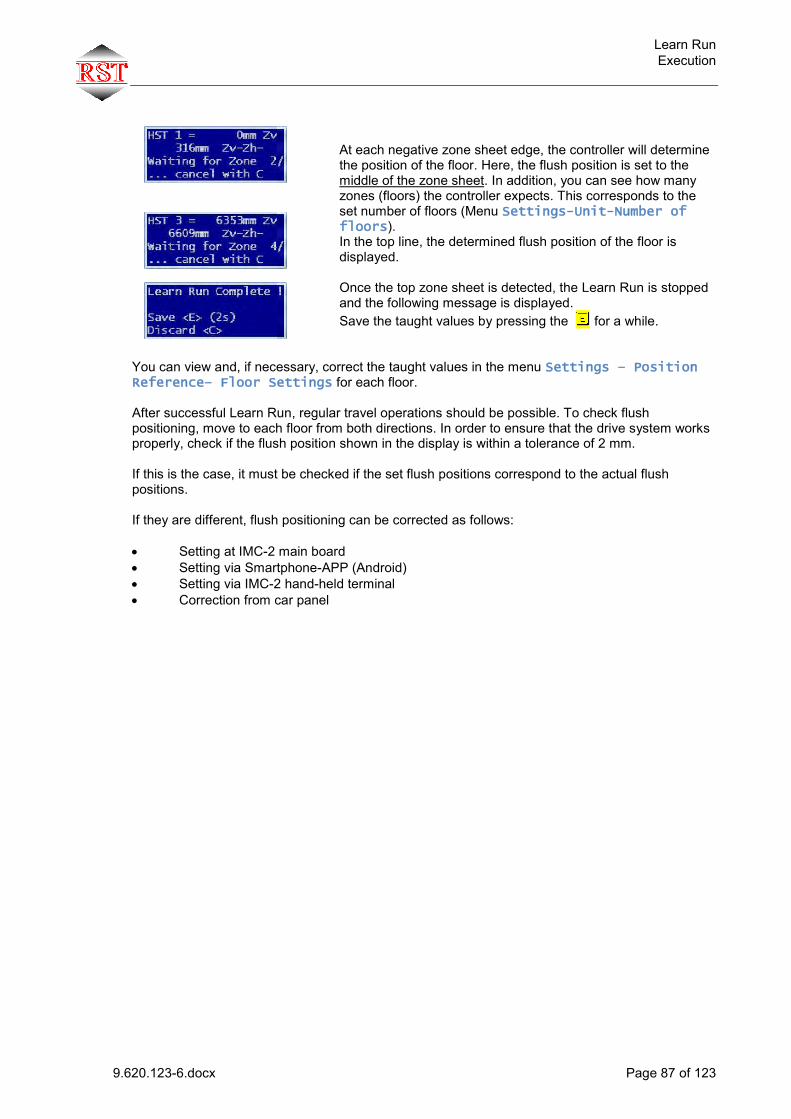
Learn Run Execution
9.620.123-6.docx Page 87 of 123
At each negative zone sheet edge, the controller will determine the position of the floor. Here, the flush position is set to the middle of the zone sheet. In addition, you can see how many zones (floors) the controller expects. This corresponds to the set number of floors (Menu Settings-Unit-Number of floors). In the top line, the determined flush position of the floor is displayed. Once the top zone sheet is detected, the Learn Run is stopped and the following message is displayed. Save the taught values by pressing the for a while.
You can view and, if necessary, correct the taught values in the menu Settings – Position Reference– Floor Settings for each floor. After successful Learn Run, regular travel operations should be possible. To check flush positioning, move to each floor from both directions. In order to ensure that the drive system works properly, check if the flush position shown in the display is within a tolerance of 2 mm. If this is the case, it must be checked if the set flush positions correspond to the actual flush positions. If they are different, flush positioning can be corrected as follows: Setting at IMC-2 main board Setting via Smartphone-APP (Android) Setting via IMC-2 hand-held terminal Correction from car panel

Setting the flush positions Flush correction via hand-held terminal or IMC-2 main board
9.620.123-6.docx Page 88 of 123
7 Setting the flush positions Before carrying out a flush correction, you will have to check if the deceleration distances are set correctly by the VVVF inverter and the controller. This is the case if the drive approaches the floor at creeping speed for approx. 1 to 2 seconds. The flush position displayed should be within a range of +-2mm irrespective of travel direction. Important: The displayed flush position only refers to the taught positions and not to the real flush position in the shaft ! When adjusting the real flush position in the shaft, the procedure will be different depending on the type of encoder (shaft encoder or motor encoder) used: Use of shaft encoder (incremental or absolute):
Move to and measure the flush deviation at each floor. The floor position can be adjusted in the shaft copying menu (see Section 0) Setup – Position Reference – Floor Settings or via the flush correction at the cabin control panel (see Section 7.2).
Use of motor encoder (incremental): Move to and measure the flush deviation at each floor (except for bottommost floor). The
floor position can be adjusted in the shaft copying menu (see Section 0) Setup – Position Reference – Floor Settings or via the flush correction at the cabin control panel (see Section 7.2).
If the flush position in up direction is correct for all floors (except for bottommost floor),
measure the deviation in down direction and correct it in Parameter Setup – Position Reference – Zone Hysteresis. The following must be noted: If the cabin is 8 mm too deep, for example, Parameter Zone Hysteresis must be set to -8 mm.
Finally check and adjust the flush position of the bottommost floor.
The following example is to illustrate how the flush correction works: After the Learn Run, the cabin is 5 mm too high in the bottommost floor. The position is to be corrected by 5 mm in down direction.
7.1 Flush correction via hand-held terminal or IMC-2 main board
Switch to menu Setup – Position Reference – Floor Settings.
After the Learn Run, the bottom most position will always be 0 mm.
Press the button to activate edit mode Use the buttons to change the parameter to – 5 mm … and save the value by pressing the button. Now, the cabin will be 5 mm deeper after the next travel operation .

Setting the flush positions Correction at cabin control panel
9.620.123-6.docx Page 89 of 123
7.2 Correction at cabin control panel Activate correction mode in Setup – Shaft copying – Level Adjust=1
menu.
After activation, the following will be displayed, the controller is now in a special mode: - inside priority activated - outside calls will not be accepted
1.) Move the cabin to the required floor. 2.) Press the Open Door button for more than 2 seconds to start the flush correction
procedure. A signal sound will indicate that the flush positions can be corrected now. When you release the buttons, all inside call buttons will light up, except for the topmost and bottommost inside call. These are now used for correcting the flush positions. Note: If you don't start the correction procedure within 60 s, the sequence will be cancelled. To restart it, press the Open Door button again.
3.) Press the topmost inside call button to change the flush position correction value by +1
mm. Press the bottommost inside call button to change the flush position correction value by -1 mm. Each correction step will be acknowledged by a signal sound. The correction values are not saved yet at this stage.
4.) The corrected values are saved by pressing the Open Door button for more than 3
seconds, saving is acknowledged by a long sound. If you press the button for a shorter time, the setup procedure will be cancelled and you will hear a series of 3 short sound signals.
5.) Move to the next floor and repeat steps 2 to 4.
Once all floors have the required flush position, you can disable correction mode by setting Setup – Shaft copying – Level Adjust=0 When there are no flush position correction activities for more than 10 minutes, this mode will be deactivated automatically.

Bypass-Operation General Information
9.620.123-6.docx Page 90 of 123
8 Bypass-Operation
8.1 General Information According to the standard EN81-20, devices for bridging the shaft door, car door or lock contacts are to be provided. These are used for maintenance or test purposes and for emergencies. The components used are to be labeled "BYPASS“. All parameters and terminal functions used in the controller are marked with the suffix "Bypass".
8.2 Functional description The complete bypass function is activated via the BypassEnable parameter in the service menu. A run in the bypass mode is only possible when the door is closed. The determination "door is closed" is realized in the inspection and return operation mode via the safety circuit. Since the safety cirquit is bridged in by-pass mode, the state "door is closed" must be determined by means of a door limit switch (door end switch) or, in the case of time-controlled doors, via a separate initiator (BypassTureZuIn). For oeration with a safety light ray, both status inputs (front + rear) must be 1. The bypass mode is activated via the input (BypassIstAus). The input is "fail-safe", the function is active if the signal is not pending. In case of a wire break the controller switches to the bypass mode and prevents a normal run. The display shows BYPASS ACTIVE. A run is now only possible via the ERO / Insp. buttons.Inspection has priority over ERO.. During the bypass run, the output BypassAktivOut is active. An input Bypass switchErrorIn allows you to wire a signal which is active if the switch position is not permitted. If the control detects this input, only inspection control can be used. Important note: In the future, car doors must always be fitted with a "door closed limit switch" !

Inspection controller General Information
9.620.123-6.docx Page 91 of 123
9 Inspection controller
9.1 General Information The inspection control has priority over the return control. In addition to the inspection control on the cabin, there is an inspection control in the pit. The controller displays which inspection inputs are activated: Inspection On Display: Inspection Cabin Inspection pit On Display: Inspektion Pit Inspection On und Inspection pit On Display: Inspektion Cb+Pit
9.2 Functionality
If only one inspection control is switched on, then you can drive with the UP or DOWN buttons (Inspection ↑, Inspection ↓, Inspection ↑ Pit, Inspection ↓ Pit).
If both cabine and pit inspections are switched on, both direction-of-travel switches must be pressed
together (with the same directional specification) for a run.
During a run, change of direction is only possible after releasing both buttons.
Special feature pit: The switching on of the pit inspection control (Inspection pit On is stored in the EEPROM. After switching off the pit inspection control, the controller remains initially locked. It can only return into normal mode after a reset signal (InspResetGrube) has been set. Alternatively, it may be possible, if certain general conditions are met, to use an outside call to reset the pit inspection. In the locked state, Insp.Grube Locked is displayed. In Locked mode, the output InspResetGrubeQuit) is set. Switching the controller off and on again does not allow the unlock. The reset signal (InspResetGrube) is also required here. After a "successful" reset, the output (InspResetGrubeQuit) is deleted.

UCM Detection (unwanted cabin movement) General
9.620.123-6.docx Page 92 of 123
10 UCM Detection (unwanted cabin movement)
10.1 General The safety monitoring module can be used in combination with the IMC-2 controller to detect unwanted cabin movements (UCM) as per EN81-A3. The identified error is saved on the IMC-2 board permanently, i.e. the controller will remain disabled even after Power Off/On. Re-commissioning and resetting of the error may only be performed by authorized persons. Monitoring of the UCM safety gear can be realized via the IMC-2 controller since the function is TÜV-certified. For more information, refer to chapter 11. For system testing, an open door is simulated. This is done by unplugging a short circuit connector in the door contact branch of the safety circuit.
10.2 Description of function If the lift moves out of the door zone area with the door open, the IMC-2 safety monitoring module will interrupt the safety circuit and the lift will stop (emergency stop). The length of the door zone must be selected such that the distances required by EN81-A3 are kept. Via the door safety circuit tapping, the controller will know that it is an EN81-A3 error and save the error permanently in the internal error memory. The error message “UCM Error” will be displayed. The plant is disabled and will remain disabled even after Power Off/On. The plant can be re-commissioned by an authorized person. This is done by deleting the error memory manually.

UCM Detection (unwanted cabin movement) Test
9.620.123-6.docx Page 93 of 123
10.3 Test
10.3.1 Preparations 1) Turn doors and outside calls off (slide switches).
2) Interrupt safety circuit in the door contact area by opening Jumper “A3 Test” at terminals X4.1 and X4.2. In this way a test can be carried out with closed doors (for safety reasons).
3) Activate EN81-A3 test in the menu.
Now, the controller will ignore the state of safety taps 3 to 5 for one travel operation and activate relay K3S (bypass of door contacts), and the travel operation can be started.
10.3.2 Execution 4) Make a call.
The controller will start a travel operation. At the end of the door zone, the safety monitoring module will interrupt the safety circuit, and an emergency stop will be actuated.
5) The controller disables the plant, displaying the message “UCM Error”.
The distance covered referred to the flush position will be displayed.
10.3.3 Check of requirements as per EN81-A3 6) Check the dimensions required as per EN81-A3. 7) Turn plant off. 8) After approx. 15 seconds (display must be dark), turn plant on again.
The error “UCM Error Eeprom” will be displayed and the plant will remain disabled.
10.3.4 Re-commissioning the plant
9) Open the menu Display/Diagnostic – Error Log: The last error will be displayed. 10) When leaving the menu, confirm the “Erase ?” prompt by pressing the E-button to
erase the error memory. 11) Turn plant off. After approx. 10 seconds (display must be dark), turn plant on again. Now,
the plant is enabled again. 12) Connect “A3 Test” again. The plant is ready for operation.
10.3.5 Regular testing The requirements as per EN81-A3 must be tested in the context of the regular testing as per Section Fehler! Verweisquelle konnte nicht gefunden werden. !
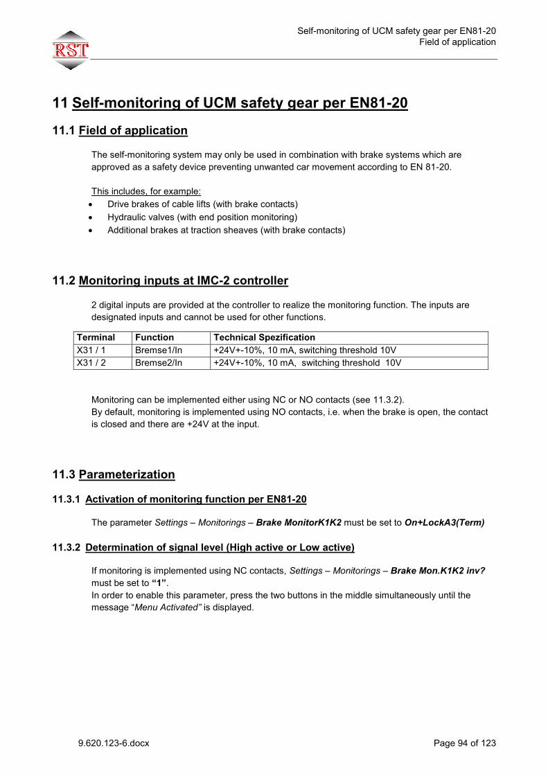
Self-monitoring of UCM safety gear per EN81-20 Field of application
9.620.123-6.docx Page 94 of 123
11 Self-monitoring of UCM safety gear per EN81-20
11.1 Field of application
The self-monitoring system may only be used in combination with brake systems which are approved as a safety device preventing unwanted car movement according to EN 81-20. This includes, for example: Drive brakes of cable lifts (with brake contacts) Hydraulic valves (with end position monitoring) Additional brakes at traction sheaves (with brake contacts)
11.2 Monitoring inputs at IMC-2 controller 2 digital inputs are provided at the controller to realize the monitoring function. The inputs are designated inputs and cannot be used for other functions.
Monitoring can be implemented either using NC or NO contacts (see 11.3.2). By default, monitoring is implemented using NO contacts, i.e. when the brake is open, the contact is closed and there are +24V at the input.
11.3 Parameterization
11.3.1 Activation of monitoring function per EN81-20 The parameter Settings – Monitorings – Brake MonitorK1K2 must be set to On+LockA3(Term)
11.3.2 Determination of signal level (High active or Low active) If monitoring is implemented using NC contacts, Settings – Monitorings – Brake Mon.K1K2 inv? must be set to “1”. In order to enable this parameter, press the two buttons in the middle simultaneously until the message “Menu Activated” is displayed.
Terminal Function Technical Spezification X31 / 1 Bremse1/In +24V+-10%, 10 mA, switching threshold 10V X31 / 2 Bremse2/In +24V+-10%, 10 mA, switching threshold 10V

Self-monitoring of UCM safety gear per EN81-20 Overview of monitored states and error messages
9.620.123-6.docx Page 95 of 123
11.3.3 Determination of wait time until check of feedback contacts After a change in actuation of the brake or valves to be monitored, an adjustable wait time will elapse before the contact feedback is checked. This time is made up of the following parameters: Setting – Monitorings – Time Brake Mon. (works set = 2000 ms) Setting – Monitorings – Brake 2 Delay (works set = 0 ms)
11.4 Overview of monitored states and error messages
Note Error state Error message Start of travel operation. Check of brake / valve contact inputs once the brake is opened
No feedback signal 1 ”Open K1”
Start of travel operation. Check of brake / valve contact inputs once the brake is opened
No feedback signal 2 ”Öpen K2”
Start of travel operation. Check of brake / valve contact inputs once the brake is opened
No feedback signal 1 and 2
”Öpen K1+K2”
End of travel operation. Check of brake / valve contact inputs once the brake is closed
Checkback signal 1 remains active
“Close K1”
End of travel operation. Check of brake / valve contact inputs once the brake is closed
Checkback signal 2 remains active
“Close K2”
End of travel operation. Check of brake / valve contact inputs once the brake is closed
Checkback signal 1 and 2 remain active
“Close K1+K2”
11.5 Resetting errors Once a brake monitoring error has occurred, the controller will be disabled – the error cannot be acknowledged. Once the controller is turned off and on, the controller will remain disabled, and the error message "BremseErrK1K2 EEP" will be displayed. To re-enable the controller, either the error memory must be deleted and then the Reset button (to the right of the display on the IMC-2 main board) must be pressed, or the board supply voltage must be turned off and on again.

Self-monitoring of UCM safety gear per EN81-20 Functional test during on-site commissioning
9.620.123-6.docx Page 96 of 123
11.6 Functional test during on-site commissioning When commissioning the controller in the lift plant, the following test must be carried out: Test A:
1. Disconnect signal at X31/1 (Bremse1/In). 2. Make call to execute a travel operation. 3. Once the travel operation has started, the message “Error Brake – Öpen K1” must be issued
after the set time Time Brake Mon., and an emergency stop is performed. In addition, the controller will be disabled (“Lock-Up” will appear on the display).
4. In this state, the controller will no longer respond to calls. 5. Reset controller by pressing the “Reset” button to the right of the display. 6. After system reset, the controller will be disabled immediately, and the error “BrakeError
EEPROM” will be displayed. 7. Delete error memory (Display – Error Log – confirm the "…erase ? <E> " prompt upon exit) 8. Reset controller again. 9. After system reset, the controller is ready for operation again, and new travel operations can be
started. 10. Start new travel operation, it must be executed without any errors.
Carry out test A as described above for input X31/2 (Bremse2/In), too. In this case, the error message is “Error Brake – Öpen K2” Test B:
1. Disconnect signal at X31/1 (Bremse1/In) and jumper +24 V voltage to X31/1. 2. Make call to execute a travel operation. 3. Once the travel operation has been completed, the message “Brake error – CloseK1” must be
issued after the set Time Brake Mon., time. In addition, the controller will be disabled (“Lock-Up” will appear on the display).
4. In this state, the controller will no longer respond to calls. 5. Reset controller by pressing the “Reset” button to the right of the display. 6. After system reset, the controller will be disabled immediately, and the error “BrakeError
EEPROM” will be displayed. 7. Delete error memory (Display – Error Log – confirm the "…erase ? <E> " prompt upon exit) 8. Reset controller again. 9. After system reset, the controller is ready for operation again, and new travel operations can be
started. 10. Start new travel operation, it must be executed without any errors.
Carry out test B as described above for input X31/2 (Bremse2/In), too. In this case, the error message is “Brake error – CloseK2”
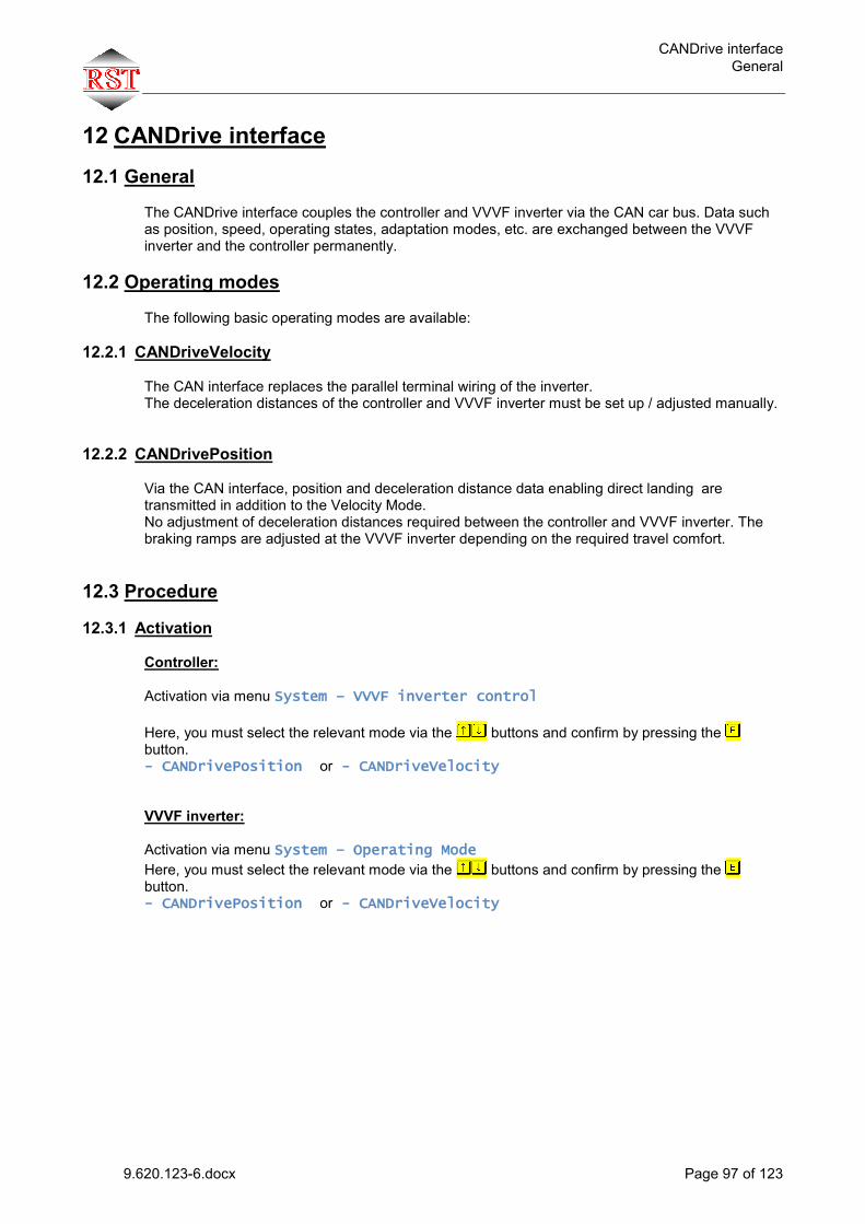
CANDrive interface General
9.620.123-6.docx Page 97 of 123
12 CANDrive interface
12.1 General The CANDrive interface couples the controller and VVVF inverter via the CAN car bus. Data such as position, speed, operating states, adaptation modes, etc. are exchanged between the VVVF inverter and the controller permanently.
12.2 Operating modes The following basic operating modes are available:
12.2.1 CANDriveVelocity The CAN interface replaces the parallel terminal wiring of the inverter. The deceleration distances of the controller and VVVF inverter must be set up / adjusted manually.
12.2.2 CANDrivePosition Via the CAN interface, position and deceleration distance data enabling direct landing are transmitted in addition to the Velocity Mode. No adjustment of deceleration distances required between the controller and VVVF inverter. The braking ramps are adjusted at the VVVF inverter depending on the required travel comfort.
12.3 Procedure
12.3.1 Activation Controller: Activation via menu System – VVVF inverter control Here, you must select the relevant mode via the buttons and confirm by pressing the button. - CANDrivePosition or - CANDriveVelocity VVVF inverter: Activation via menu System – Operating Mode Here, you must select the relevant mode via the buttons and confirm by pressing the button. - CANDrivePosition or - CANDriveVelocity
CANDrive interface Procedure
9.620.123-6.docx Page 98 of 123
12.3.2 Calibration in CANDrivePosition mode To ensure correct function, the positioning systems of the VVVF inverter and the controller must be adjusted to one another. To do this, you should set the following plant data in the VVVF inverter first - menu Setting – General Settings: Transmission ratio Pulley diameter Suspension If you do not know all of the above plant data, please set plausible data for the VVVF inverter to have a reasonable basis for calibration. Example: Transmission ratio->53:2=2650, Pulley diameter = 500mm, Suspension=1. If the Learn Run was already performed in CANDrivePosition mode, the system is calibrated after that. If the CANDrivePosition mode was activated at a later stage, the system must be calibrated in a return travel operation: Switch the controller to “Return” Before the travel operation, open the VVVF inverter menu Setting – CANDrive –
Adapt OK. At first, this parameter is set to 0. In return mode, move through the shaft. After a distance of 1 m, VVVF inverter parameter
Adapt OK switches from 0 to 1. Now, the system is calibrated. The display value Adapt INK/M in the VVVF inverter menu Setting – CANDrive indicates how many encoder increments were counted per meter (used for error diagnosis only). The display value DDrive Adapt indicates which Drive pulley diameter is used by the VVVF inverter based on the calibration travel operation (only used for error diagnosis). With the plant data set correctly, this value should be close to the real drive pulley diameter.
Now, the controller can be switched to normal operation mode.
12.3.3 Special features in CANDrivePosition mode Travelling to flush position with non-flush cabin after Controller Power On or after changeover from return to normal operation mode is always done at VN, provided that the cabin is in the zone area. If the cabin is not in the zone, the travel profile used for travelling to the flush position is based on the remaining distance. If this is not the case, Stopping distance V2 must be reduced to 10 mm in the controller menu Setup – Shaft copying.
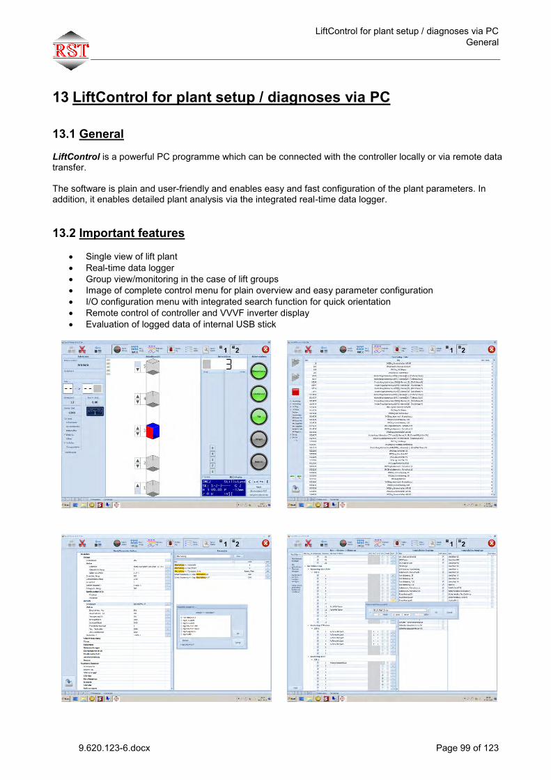
LiftControl for plant setup / diagnoses via PC General
9.620.123-6.docx Page 99 of 123
13 LiftControl for plant setup / diagnoses via PC
13.1 General
LiftControl is a powerful PC programme which can be connected with the controller locally or via remote data transfer. The software is plain and user-friendly and enables easy and fast configuration of the plant parameters. In addition, it enables detailed plant analysis via the integrated real-time data logger. 13.2 Important features
Single view of lift plant Real-time data logger Group view/monitoring in the case of lift groups Image of complete control menu for plain overview and easy parameter configuration I/O configuration menu with integrated search function for quick orientation Remote control of controller and VVVF inverter display Evaluation of logged data of internal USB stick

Remote monitoring via Monitoring System Important features
9.620.123-6.docx Page 100 of 123
14 Remote monitoring via Monitoring System
The IMC-2 Monitoring System is based on an online solution. It can be accessed through any computer connected to the Internet using any Internet browser and operating system (Windows, Linux, Mac).
It provides all relevant information about your lift plant (e.g. error messages, door cycles, travel operations, loading) and collects background data enabling fault/error forecasts. The configurable message function reports faults/errors and warnings automatically. The faults/errors and warnings can automatically be sent either through SMS messages or by e-mail.
For more information, refer to document “IMC-2 Monitoring System”.
Monitoring-Server
Internet
) ) ) ) )
) ) ) ) )
Monitoring-WebportalAufzugsanlagen mitMobilfunkmodem
GSM-Netz
Group mode General
9.620.123-6.docx Page 101 of 123
15 Group mode
15.1 General IMC-2 features powerful group software enabling optimum traffic control. No separate group controller is required. For more specifications, consult RST.
15.2 Description of system Group communication takes place via the shaft bus, which is also used for the outside panels. After Power On, the IMC-2 group controllers will determine which controller will be the Master . The other group members will be Group Clients . The Group Master controls the whole traffic and ensures that outside calls will be processed as quickly as possible. The Group Clients are communicating all the time. This makes sure that lifts which are no longer in group mode (e.g. because it was switched to inspection mode) are immediately identified and no longer considered for call assignments. If the Group Master is shut down, one of the Clients will perform the Master function. It will remain the Master even after re-commissioning of the original Group Master. A group bus module (GBM) is required for coupling the group clients. On the following page, you will see an illustration showing a schematic circuit diagram of a group of two.

Group mode Group of 2 - Schematic circuit diagram
9.620.123-6.docx Page 102 of 123
15.3 Group of 2 - Schematic circuit diagram
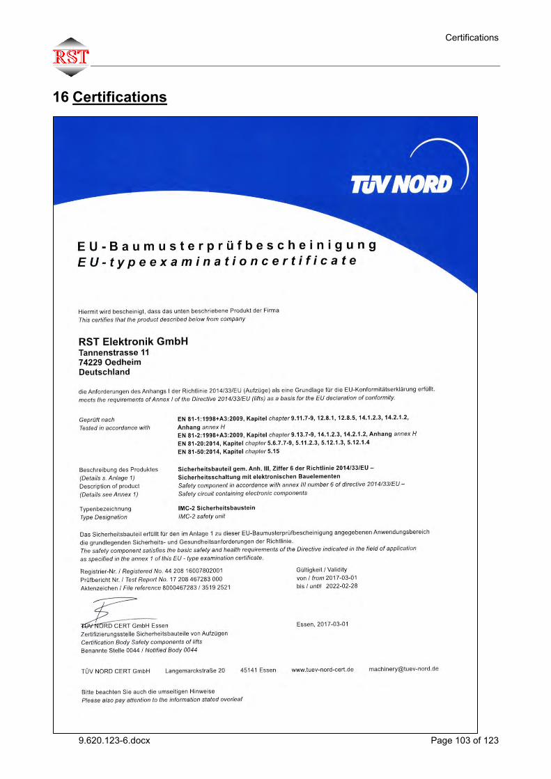
Certifications
9.620.123-6.docx Page 103 of 123
16 Certifications

Certifications
9.620.123-6.docx Page 104 of 123

Certifications
9.620.123-6.docx Page 105 of 123

Certifications
9.620.123-6.docx Page 106 of 123

Certifications
9.620.123-6.docx Page 107 of 123
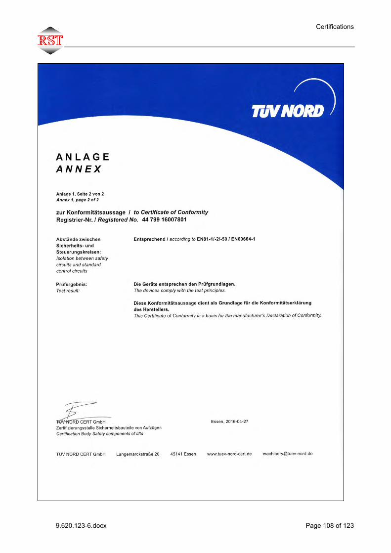
Certifications
9.620.123-6.docx Page 108 of 123
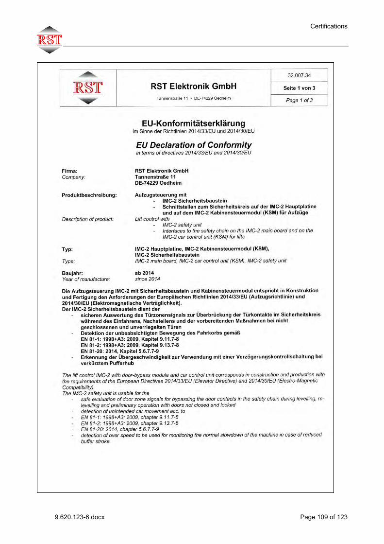
Certifications
9.620.123-6.docx Page 109 of 123

Certifications
9.620.123-6.docx Page 110 of 123
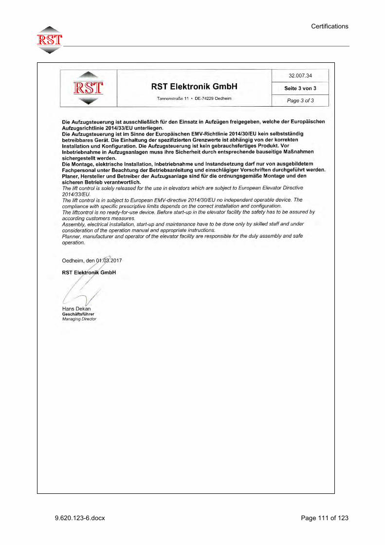
Certifications
9.620.123-6.docx Page 111 of 123

Certifications
9.620.123-6.docx Page 112 of 123
Certifications
9.620.123-6.docx Page 113 of 123

Certifications
9.620.123-6.docx Page 114 of 123

Certifications
9.620.123-6.docx Page 115 of 123
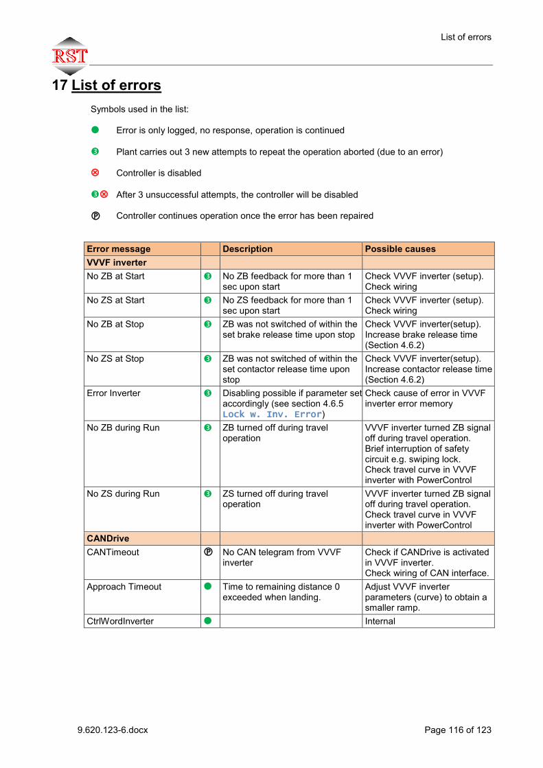
List of errors
9.620.123-6.docx Page 116 of 123
17 List of errors Symbols used in the list: Error is only logged, no response, operation is continued Plant carries out 3 new attempts to repeat the operation aborted (due to an error) Controller is disabled After 3 unsuccessful attempts, the controller will be disabled Controller continues operation once the error has been repaired
Error message Description Possible causes VVVF inverter No ZB at Start No ZB feedback for more than 1
sec upon start Check VVVF inverter (setup). Check wiring
No ZS at Start No ZS feedback for more than 1 sec upon start
Check VVVF inverter (setup). Check wiring
No ZB at Stop ZB was not switched of within the set brake release time upon stop
Check VVVF inverter(setup). Increase brake release time (Section 4.6.2)
No ZS at Stop ZB was not switched of within the set contactor release time upon stop
Check VVVF inverter(setup). Increase contactor release time (Section 4.6.2)
Error Inverter Disabling possible if parameter set accordingly (see section 4.6.5 Lock w. Inv. Error)
Check cause of error in VVVF inverter error memory
No ZB during Run ZB turned off during travel operation
VVVF inverter turned ZB signal off during travel operation. Brief interruption of safety circuit e.g. swiping lock. Check travel curve in VVVF inverter with PowerControl
No ZS during Run ZS turned off during travel operation
VVVF inverter turned ZB signal off during travel operation. Check travel curve in VVVF inverter with PowerControl
CANDrive CANTimeout No CAN telegram from VVVF
inverter Check if CANDrive is activated in VVVF inverter. Check wiring of CAN interface.
Approach Timeout Time to remaining distance 0 exceeded when landing.
Adjust VVVF inverter parameters (curve) to obtain a smaller ramp.
CtrlWordInverter Internal

List of errors
9.620.123-6.docx Page 117 of 123
Safety monitoring module Active Error from module Passive Error from module Safety circuit Supply No SK1 tap Passive No SK2 tap Door No SK3 tap Lock No SK4 tap Emerg.Stop No SK5 tap Passiv EEPROM Error-memory contains an error
„Passive“.
Brake K1K2 Open K1
Error when opening Contact 1 Contact 1 and 2 monitoring can
be deactivated by changing parameter settings (see Section 0). Wait time is 3 s
Open K2
Error when opening Contact 2 see above
Open contactor
Error when opening brake contactor
see above
Open K1+K2
Error when opening Contact 1+2 see above
Open K1+contactor
Error when opening Contact 1+brake contactor
see above
Open K2+contactor
Error when opening Contact 2+brake contactor
see above
Open K1+K2+contactor
Error when opening Contact 1+2+brake contactor
see above
Close K1
Error when closing Contact 1 see above
Close K2
Error when closing Contact 2 see above
Close contactor
1Error when closing brake contactor
see above
Close K1+K2
Error when closing Contact 1+2 see above
Close K1+contactor
Error when closing Contact 1+brake contactor
see above
Close K2+contactor
Error when closing Contact 2+brake contactor
see above
Close K1+K2+contactor
Error when closing Contact 1+2+brake contactor
see above
BremseErrK1K2EEP Error-memory contains a error „Brake K1K2“.
Bremse K3K4 Siehe „Bremse K1K2“
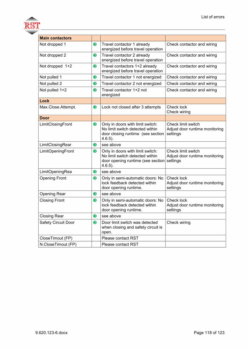
List of errors
9.620.123-6.docx Page 118 of 123
Main contactors Not dropped 1 Travel contactor 1 already
energized before travel operation Check contactor and wiring
Not dropped 2 Travel contactor 2 already energized before travel operation
Check contactor and wiring
Not dropped 1+2 Travel contactors 1+2 already energized before travel operation
Check contactor and wiring
Not pulled 1 Travel contactor 1 not energized Check contactor and wiring Not pulled 2 Travel contactor 2 not energized Check contactor and wiring Not pulled 1+2 Travel contactor 1+2 not
energized Check contactor and wiring
Lock Max.Close.Attempt. Lock not closed after 3 attempts Check lock
Check wiring Door LimitClosingFront Only in doors with limit switch:
No limit switch detected within door closing runtime (see section 4.6.5).
Check limit switch Adjust door runtime monitoring settings
LimitClosingRear see above LimitOpeningFront Only in doors with limit switch:
No limit switch detected within door opening runtime (see section 4.6.5).
Check limit switch Adjust door runtime monitoring settings
LimitOpeningRea see above Opening Front Only in semi-automatic doors: No
lock feedback detected within door opening runtime.
Check lock Adjust door runtime monitoring settings
Opening Rear see above Closing Front Only in semi-automatic doors: No
lock feedback detected within door opening runtime.
Check lock Adjust door runtime monitoring settings
Closing Rear see above Safety Circuit Door Door limit switch was detected
when closing and safety circuit is open.
Check wiring
CloseTimout (FP) Please contact RST N.CloseTimout (FP) Please contact RST
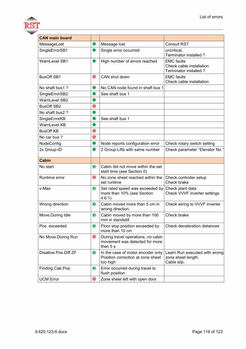
List of errors
9.620.123-6.docx Page 119 of 123
CAN main board MessageLost Message lost Consult RST SingleErrorSB1 Single error occurred uncritical,
Terminator installed ? WarnLevel SB1 High number of errors reached EMC faults
Check cable installation Terminator installed ?
BusOff SB1 CAN shut down EMC faults Check cable installation
No shaft bus1 ? No CAN node found in shaft bus 1 SingleErrorSB2: See shaft bus 1 WarnLevel SB2 BusOff SB2 No shaft bus2 ? SingleErrorKB See shaft bus 1 WarnLevel KB BusOff KB No car bus ? NodeConfig Node reports configuration error Check rotary switch setting 2x Group-ID 2 Group-Lifts with same number
Check parameter “Elevator No.”
Cabin No start Cabin did not move within the set
start time (see Section 0)
Runtime error No zone sheet reached within the set runtime
Check controller setup Check brake
v-Max Set rated speed was exceeded by more than 10% (see Section 4.6.1)
Check plant data Check VVVF inverter settings
Wrong direction Cabin moved more than 5 cm in wrong direction.
Check wiring to VVVF inverter
Move.During Idle Cabin moved by more than 100 mm in standstill
Check brake
Pos. exceeded Floor stop position exceeded by more than 10 cm
Check deceleration distances
No Move.During Run During travel operations, no cabin movement was detected for more than 5 s
Disallow.Pos.Diff.ZF In the case of motor encoder only: Position correction at zone sheet too high
Learn Run executed with wrong zone sheet length. Cable slip.
Finding Cab.Pos. Error occurred during travel to flush position.
UCM Error Zone sheet left with open door.

List of errors
9.620.123-6.docx Page 120 of 123
UCM Error EEPROM UCM Error in error memory Delete error memory Target-Zone Error No zone signal detected in the
destination floor zone
V/max Decel.cont. The parametrized speed at deceleration point was overceedeed
IO Config MemberID Consult RST NodeID Consult RST Note not ex. No CAN node existing for I/O
function Check wiring CAN node defective
Terminal not ex. No terminal existing for I/O function
Check wiring CAN node defective
EepromSaveOverflow Consult RST ChecksumError Consult RST No assignments Consult RST Internal RTC module Consult RST Para EEPROM Consult RST Data EEPROM Consult RST I2C Bus Consult RST SSI Open/Short Cir.? Consult RST No ErrCode Consult RST TaskOverflow Consult RST Number Para. Consult RST StrSize Consult RST Encoder value range SSI encoder position is outside of
topmost and bottommost floor.
Toothed belt of shaft copying not tensioned. Carry out new Learn Run
SSI-ErrDetection Consult RST AD not valid Consult RST ImpulsErrMAXEncod Consult RST EEP address conflict Consult RST EEP MasNum WrCycl Consult RST EEP NoWr24VLow Consult RST ALFAT RxAnzahl Consult RST Light ray Light Ray Inter. Light grid safety range interrupted
during travel operation
Light Ray Test Err
Light grid test before start of travel operation failed
Check wiring and light grid

List of errors
9.620.123-6.docx Page 121 of 123
Travel contactors Not dropped 1 Contactor 1 not deenergized Check wiring and light grid Not dropped 2 Contactor 2 not deenergized see above Not dropped 1+2 Contactors 1+2 not deenergized see above Not pulled 1 Contactor 1 not energized see above Not pulled 2 Contactor 2 not energized see above Not pulled 1+2 Contactors 1+2 not energized see above Other Motor temperature Motor temperature too high Oil temperature Oil temperature too high Overtemperature Electrical cabinet temperature too
high
+24V Low Board supply voltage too low Power supply overloaded or defective, board defective
Car Light Cabin light monitor reports error Check cabin light, adjust threshold if necessary (see Section 0)
HSSLow(Busk.schl?) Consult RST Level>MAX Flush tolerance above set limit Check stopping distances of
controller and VVVF inverter P.Supply Alarm-Batt. Power supply reports battery
alarm Low battery level
ANS Run Without PC Misuse safeguard actuated Max. number of travel operations without light barrier interruption exceeded.
ANS Alarm Emergency call misuse safeguard was actuated.
ANS Max.No Car Calls Max. number of inside calls misuse safeguard was actuated
ANS Empty Car Empty load misuse safeguard was actuated.
Photocell MaxTime Maximum light barrier interruption time exceeded
Zone error Internal zone monitor was actuated
Zone switch defective or hanging temporarily
Max. Rope-Slip The measured cable slip is above the set maximum
Hanging Call? Permanent signal at a call-input Mon.TerminalLow
or
Signal at input „Monitoring Term.“ was low
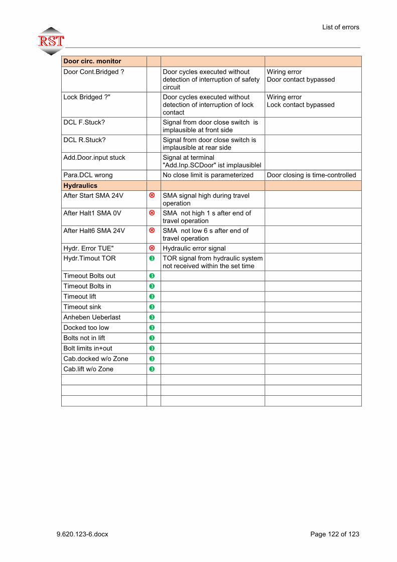
List of errors
9.620.123-6.docx Page 122 of 123
Door circ. monitor Door Cont.Bridged ? Door cycles executed without
detection of interruption of safety circuit
Wiring error Door contact bypassed
Lock Bridged ?" Door cycles executed without detection of interruption of lock contact
Wiring error Lock contact bypassed
DCL F.Stuck? Signal from door close switch is implausible at front side
DCL R.Stuck? Signal from door close switch is implausible at rear side
Add.Door.input stuck Signal at terminal "Add.Inp.SCDoor" ist implausiblel
Para.DCL wrong No close limit is parameterized Door closing is time-controlled Hydraulics After Start SMA 24V SMA signal high during travel
operation
After Halt1 SMA 0V SMA not high 1 s after end of travel operation
After Halt6 SMA 24V SMA not low 6 s after end of travel operation
Hydr. Error TUE" Hydraulic error signal Hydr.Timout TOR TOR signal from hydraulic system
not received within the set time
Timeout Bolts out Timeout Bolts in Timeout lift Timeout sink Anheben Ueberlast Docked too low Bolts not in lift Bolt limits in+out Cab.docked w/o Zone Cab.lift w/o Zone

Index
9.620.123-6.docx Page 123 of 123
18 Index
Accidental calls .................................................. 80 Assembly mode ................................................. 81 Attic .................................................................... 66 Brake monitoring ................................................ 68 buffer-test ........................................................... 82 Bypass-Betrieb .................................................. 90 Cabin control module ......................................... 19 Cabin controller module terminals ..................... 22 Cabin light monitoring ........................................ 69 Cabin start monitoring ........................................ 69 CAN bus............................................................. 44 CANDrive interface ............................................ 97 Car operation panel ........................................... 34 Car operation panel terminals ........................... 36 Car position indicator module ............................ 32 Code number ..................................................... 78 Data remote control ........................................... 99 Delete statistics counters ................................... 83 Design test certificate ...................................... 103 Direct landing ..................................................... 97 Disable calls ....................................................... 80 Disabling floors .................................................. 81 Display services ................................................. 81 Door times, graphical representation ................. 62 Eco mode ........................................................... 70 ELGO LIMAX ..................................................... 85 Emergency power .............................................. 65 EN81 – A3 Detection of unwanted cabin
movement. ..................................................... 92 EN81 A3 test travel operation ............................ 82 Error memory ..................................................... 73 Fire alarm 1 ........................................................ 64 Flash Loader ...................................................... 79 Flush correction ................................................. 88 Flush monitoring ................................................ 69 Group ................................................................. 72 Group Client ..................................................... 101 Group Master ................................................... 101 Group mode ..................................................... 101 Hand-held terminal ............................................ 40 Hazards.............................................................. 10 I/O functions, programming ............................... 84 Indicators menu ................................................. 73 Inputs/outputs, programming ............................. 84 inspection controller ........................................... 91 LiftControl .......................................................... 99 List of errors ..................................................... 116 Main board (module) .......................................... 13 Main board terminals ......................................... 15 Making calls ....................................................... 80 Max. el. cabinet temperature ............................. 69
Menu and operation .......................................... 47 Menu parameter, access ................................... 78 Menu structure, general overview ..................... 49 Misuse protection, functions .............................. 71 Modules ............................................................. 13 Monitoring .......................................................... 99 Monitoring, Einstellungen .................................. 83 Monitoring+Fernzugriff, Anzeigen ..................... 76 Motor incremental encoder................................ 85 motor temperature supervision ......................... 68 Node IDs, setting ............................................... 44 Operating elements, main board ....................... 15 Park ............................................................. 65, 66 PC programme .................................................. 99 Plant analysis .................................................... 99 Port Expander Module ....................................... 30 Port expander module terminals ....................... 31 Priority ............................................................... 63 Rampensteuerung ............................................. 66 Regular testing .................................................. 93 Rotary encoder switch ....................................... 20 Safety monitoring module.................................. 41 Safety monitoring module terminals .................. 42 Safety regulations ........................................ 10, 11 Set door parameters .......................................... 60 Set time/date ..................................................... 77 Setting the service interval ................................ 83 Setup menu ....................................................... 56 Setup of drive parameters ................................. 57 Setup of monitors .............................................. 68 Setup of plant data ............................................ 56 Shaft copying systems ...................................... 85 Shaft copying, set paths .................................... 58 Shaft incremental encoder ................................ 85 Show actual values ........................................... 75 Show calls ......................................................... 76 Show CAN bus .................................................. 73 Show inputs/outputs .......................................... 74 Show software version ...................................... 76 Show statistics ................................................... 76 Software update ................................................ 79 SSI absolute encoder ........................................ 85 Teach travel operation ....................................... 86 Test runtime monitoring ..................................... 82 Travelling cable ................................................. 45 TÜV / Test, menu .............................................. 82 Universal Bus Module (UBM) ...................... 28, 39 Universal bus module terminals ........................ 29 USB host ........................................................... 78 VVVF controller actuation.................................. 77