electrostatic comic dust collector...
TRANSCRIPT

High Altitude Student Platform (HASP) 2016
Electrostatic Comic Dust Collector (ECDC) Science Report
College of The Canyons 26455 Rockwell Canyon Rd
Santa Clarita, CA 91355
Payload class: Small Payload number: 02 Flight number: 670N
Flight time: 9/1/2016 16:08 UTC - 9/2/2016 9:41:28 UTC Time at float: 15H:08M:54s

Electrostatic Comic Dust Collector (ECDC) HASP 2016 Science Report
Table of Contents A. Table of acronyms. . . . . . . . . . . . . . . . . . . . . . . . . . . . . . . . . . . . . . . . . . . . . . . . . . . . . . . . . . . . .2
I. Abstract . . . . . . . . . . . . . . . . . . . . . . . . . . . . . . . . . . . . . . . . . . . . . . . . . . . . . . . . . . . . . . . . 3 II. Introduction. . . . . . . . . . . . . . . . . . . . . . . . . . . . . . . . . . . . . . . . . . . . . . . . . . . . . . . . . . . . . . 3
A. Concept . . . . . . . . . . . . . . . . . . . . . . . . . . . . . . . . . . . . . . . . . . . . . . . . . . . . . . . . . . 3 B. Principle of Operation . . . . . . . . . . . . . . . . . . . . . . . . . . . . . . . . . . . . . . . . . . . . . . . . 4
III. Fabrication. . . . . . . . . . . . . . . . . . . . . . . . . . . . . . . . . . . . . . . . . . . . . . . . . . . . . . . . . . . . . . .5 A. Mechanical Systems. . . . . . . . . . . . . . . . . . . . . . . . . . . . . . . . . . . . . . . . . . . . . . . . . .5 B. Electronic Systems. . . . . . . . . . . . . . . . . . . . . . . . . . . . . . . . . . . . . . . . . . . . . . . . . . .6 C. Thermal System. . . . . . . . . . . . . . . . . . . . . . . . . . . . . . . . . . . . . . . . . . . . . . . . . . . . . 9 D. EPC System. . . . . . . . . . . . . . . . . . . . . . . . . . . . . . . . . . . . . . . . . . . . . . . . . . . . . . . 11
IV. Integration . . . . . . . . . . . . . . . . . . . . . . . . . . . . . . . . . . . . . . . . . . . . . . . . . . . . . . . . . . . . . .12 V. Flight. . . . . . . . . . . . . . . . . . . . . . . . . . . . . . . . . . . . . . . . . . . . . . . . . . . . . . . . . . . . . . . . . . 14
VI. Post-flight Analysis. . . . . . . . . . . . . . . . . . . . . . . . . . . . . . . . . . . . . . . . . . . . . . . . . . . . . . . .17 VII. Results. . . . . . . . . . . . . . . . . . . . . . . . . . . . . . . . . . . . . . . . . . . . . . . . . . . . . . . . . . . . . . . . .20
A. Computer Models & Simulations. . . . . . . . . . . . . . . . . . . . . . . . . . . . . . . . . . . . . . . . 21 B. Sample Retrieval. . . . . . . . . . . . . . . . . . . . . . . . . . . . . . . . . . . . . . . . . . . . . . . . . . . 23
VIII. Conclusion. . . . . . . . . . . . . . . . . . . . . . . . . . . . . . . . . . . . . . . . . . . . . . . . . . . . . . . . . . . . . . 24 A. Failure analysis & lessons learned . . . . . . . . . . . . . . . . . . . . . . . . . . . . . . . . . . . . . . 24 B. Future work . . . . . . . . . . . . . . . . . . . . . . . . . . . . . . . . . . . . . . . . . . . . . . . . . . . . . . .25
IX. Team. . . . . . . . . . . . . . . . . . . . . . . . . . . . . . . . . . . . . . . . . . . . . . . . . . . . . . . . . . . . . . . . . . 26 X. References. . . . . . . . . . . . . . . . . . . . . . . . . . . . . . . . . . . . . . . . . . . . . . . . . . . . . . . . . . . . . .29
1
Electrostatic Comic Dust Collector (ECDC) HASP 2016 Science Report
A. Table of Acronyms
HASP High Altitude Student Platform
LSU Louisiana State University
NASA National Aeronautics and Space Agency
ECDC Electrostatic Comic Dust Collector
IDP Interplanetary Dust Particle
EPC Electrostatic Particle Collector
PSIP Payload Specification and Integration Plan
FLOP FLight Operations Plan
ATC Active Thermal Control
PTC Passive Thermal Control
CSUN California State University Northridge
PMB Power Management Board
2

Electrostatic Comic Dust Collector (ECDC) HASP 2016 Science Report
I. Abstract The electrostatic cosmic dust collector (ECDC) experiment uses a small payload position on the 2016 HASP launch to capture and study passive Interplanetary Dust Particles (IDPs). The capture of IDPs for study has been primarily restrained to expensive long-duration high altitude flights, instrumentation on the International Space Station in orbit, or spacecraft trailing an active cometary coma. IDPs primarily originate from meteor showers and natural interplanetary-medium flux that are typically collected in the form of smoke particles. Through the use of a high voltage electrostatic precipitator, passive IDPs of the full spectrum of size and composition can be actively captured from the stratosphere for further analysis. This method has never been used to capture IDPs and this experiment seeks to determine its effectiveness. All criteria of mass, power consumption, and structural support have been met according to HASP guidelines.
II. Introduction Concept With 2016 being the first year the ECDC team has ever participated in HASP, there was a serious learning curve to be overcome in order to produce a reliable and functional payload capable of performing in the hostile high-altitude environment. The electrostatic cosmic dust collector is a proof-of-concept design developed by team manager and project principal investigator Daniel Tikhomirov, in order to capture IDPs with the use of an electrostatic precipitator. The main science goal of this flight was to run a full test of the collector system at the operational voltage of 10kV as intended in the design to determine how well it performs. The end goal of this project is to develop a refined version of this collector that is able to collect passive transient IDPs in the upper stratosphere using a balloon platform as a cheaper alternative to current dust-collection methods with similar collection efficiencies. Possible applications of this technology could be applied to future mars missions if airborne particulate collection needed to be performed at ground-level by robotic or manned missions.
Figure1. ECDC payload CAD design Figure2. Flight-ready ECDC Payload (Aug. 2016)
3

Electrostatic Comic Dust Collector (ECDC) HASP 2016 Science Report
Principle of Operation The way the electrostatic particle collector works is the same basic concept as an electrostatic precipitator found in most large air filtering systems of buildings. A high voltage, 10kV in our case, is given to a large electrode that has the task of collecting the dust particles. The ground of that same high voltage supply will be connected to another electrode away from the collecting plate and in front of the incoming stream of air. This grounded electrode will then gave a strong negative charge, capable of ionizing any particles that come in with the air flow. Once the particles become ionized, they will accelerate towards the positive collecting electrode and “stick” to the plate. The negative electrode in our experiment was chosen to be a copper mesh, the best form to not impede air flow yet still achieve maximum ionization with smaller gaps between the ionizing wires. The collection plate is a simple copper plate placed 2.5cm below the mesh that will gather the particles after ionization.
Figure3. Electrostatic particle collector concept diagram
Once the collection plate had collected the samples that were needed, the enclosure inside of which the collector is housed would close to create a contaminant-proof seal. This enclosure would be opened inside a clean room and a pure acrylic resin would be poured onto the plate inside of a mold to embed the particles in a hardened and transparent acrylic. Acrylic could also then be chemically dissolved to free the particles captured with altering the composition or morphology using chloroform vapor.
4

Electrostatic Comic Dust Collector (ECDC) HASP 2016 Science Report
III. Design & Fabrication Mechanical Systems One of the main challenges for this flight was to construct a payload able to withstand the environmental extremes expected at high altitude for long durations and still perform its task. Materials were chosen for their ability to withstand freezing temperatures and shocks upon possible rough starts and especially landings. With the main goal of the experiment being to get the cosmic dust samples down to earth uncontaminated, the payload must have been able to remain intact after landing.
Being a team from a community-college, there were workforce training facilities on campus that allowed for advanced manufacturing to be done on the payload mechanical systems. This allowed us to build two separate mechanical payloads with one being used for testing and the other for flight. By that approach, all parts were created and tested by building the test article and the flight article received only the highest quality and most-refined parts from the fabrication. Lightweight aluminum 6061 was used for the top and bottom plates of the payload while rigid aluminum 2024 panels and 6061 side extrusions supported the payload structure. The plates were milled with a CNC mill to create weight-reduction pockets which cut the weight of both plates down by 54%. This lightweight and simple payload structure, once completed, turned out to be much more robust and shock-resistant than previously anticipated. However, this system did undergo major design changes throughout the dynamic project timeline.
Figure4. CNC-milled bottom support plate Figure5. Payload during assembly & fabrication
A design fault that was discovered once the payload frame was completed in mid-May was the fact that the EPC enclosure was able to be easily pried open once it was shut by the actuator. This would have proved a problem for landing where the shock could easily crack open the lid for a split second and contaminate the sample with terrestrial dust. Luckily the mechanical lead Patrick Gagnon along with Daniel Tikhomirov and manufacturing advisor Greg Poteat devised a solution using a spring subassembly to add spring tension to the main EPC closing assembly. This way, when the actuator fully extended, the spring would create tension on the lift arm and give some extra static tension on the lid of the EPC enclosure. The spring that was chosen did not need to travel a significant distance to add the static pressure so the issue of sub-zero temperatures causing a critical failure were low.
5

Electrostatic Comic Dust Collector (ECDC) HASP 2016 Science Report
However, in another twist to the design of the mechanical system of the payload, it turned out that too much force was added by the spring. The force of the spring caused the backside edge of the EPC enclosure to lift very slightly off of the O-ring because most of the force was put on a loose hinge. This problem was fixed by using an arbor press to compress the hinge pivot point to reduce the movement tolerance. The spring assembly was also set up so that the force of the spring was able to be changed by adjusting 4 screws to a certain depth using a set gauge. This problem could have been easily solved by moving the hinge from the polycarbonate enclosure to an offset rigid pivot point to direct the force onto the pivot point and not the fragile enclosure. This change is further discussed in future work as a possible alternative design for future flights. Electrical Systems Designing the electrical systems turned out to be a larger challenge than was anticipated, with major design changes happening all the way up to the final PSIP. It was decided during the proposal design phase in November that the serial uplink and downlink capabilities would be too complex to design in time for the proposal submission in December, mainly due to our limited digital communications research and background. The team’s only previous experience was with conventional weather balloon payloads that revolved around fully-autonomous systems that relied on camera subsystems to confirm experiment success. With that in mind, the team decided to take a “limited in-flight supervision” approach, which meant that the payload would launch with a pre-programmed mission and come down with the results upon landing. After the proposal acceptance, HASP officials decided that this approach would be risky and advised the team to add some kind of in-flight function tracking capabilities to make sure that the payload was functioning as it should. It was decided in late January that it would be in our best interest to follow this advice and run through a design change to add some more capabilities. Temperature analog tracking through the analog downlink was added; a serious benefit, but as it would turn out later to be not nearly enough. The payload electrical systems were designed to be run on a programmed Arduino Uno with additional “shields”, or stacked PCB’s that expand the functions of the Uno. This simple and modular design gave the team the ability to stack different PCB’s with unique functions to control onboard payload systems. The Uno also had the added benefit of having a compact size that was able to fit into the standard small-payload class size restrictions of 15cm x 15cm. The flight computer was powered by a custom-designed power management board (PMB) capable of converting the 30VDC given by HASP into the various voltages needed by the payload systems. The PMB was located on an adjacent panel from the flight computer and was wired to the computer through a molex connector bus. The PMB also housed the HASP power and discrete signal interface, heater power control, and the high voltage power converter. The board was soldered together using a prototyping board that was suitable for the purpose of a simple power interface capable of surviving the environment expected during flight. The wiring schematic proved to be a downside of the proto-board with the amount of wires being needed becoming a hassle to solder and route.
6

Electrostatic Comic Dust Collector (ECDC) HASP 2016 Science Report
Figure6a. Flight computer, power management Figure6b. Assembled test payload with internal board, electronics & motor assembly configuration. flight components.
Figure6c. Flight computer and power management Figure6d. Assembled flight payload with board proximity and wire interconnections. flight components and insulation
7
Electrostatic Comic Dust Collector (ECDC) HASP 2016 Science Report
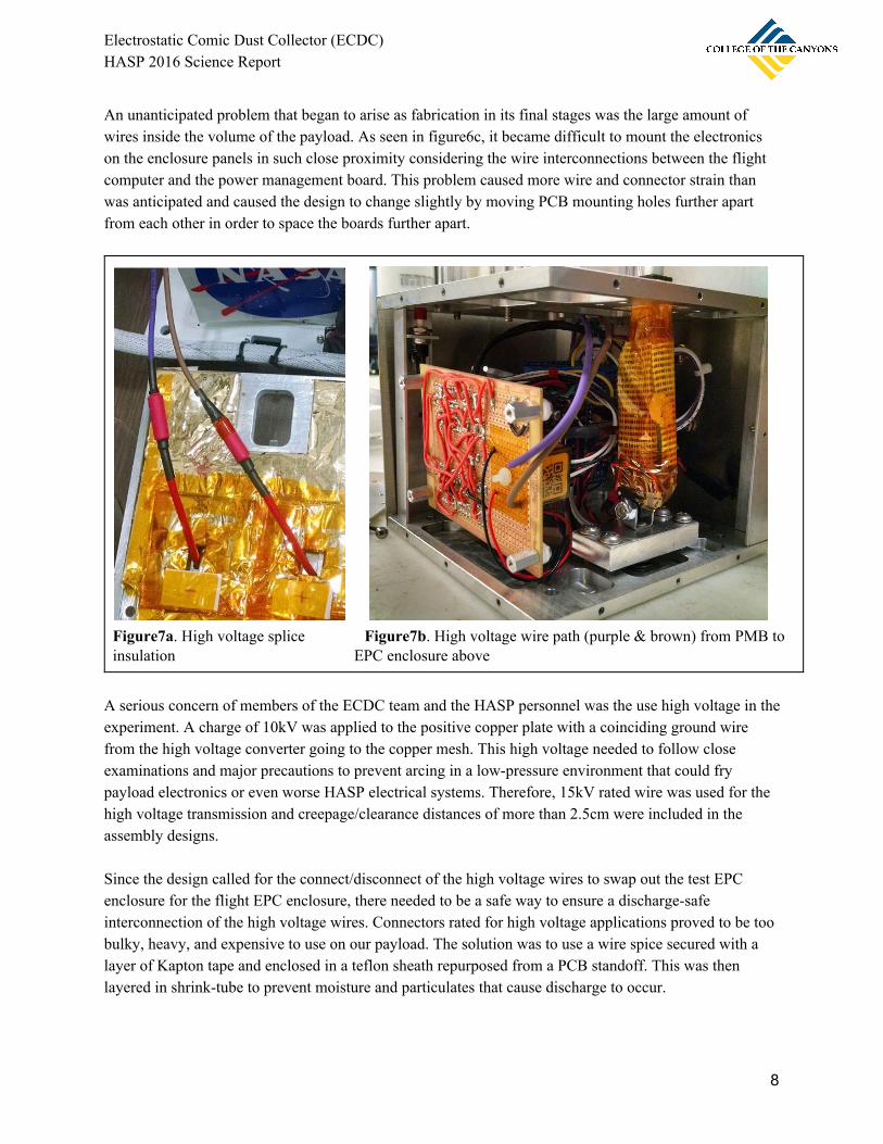
An unanticipated problem that began to arise as fabrication in its final stages was the large amount of wires inside the volume of the payload. As seen in figure6c, it became difficult to mount the electronics on the enclosure panels in such close proximity considering the wire interconnections between the flight computer and the power management board. This problem caused more wire and connector strain than was anticipated and caused the design to change slightly by moving PCB mounting holes further apart from each other in order to space the boards further apart.
Figure7a. High voltage splice Figure7b. High voltage wire path (purple & brown) from PMB to insulation EPC enclosure above
A serious concern of members of the ECDC team and the HASP personnel was the use high voltage in the experiment. A charge of 10kV was applied to the positive copper plate with a coinciding ground wire from the high voltage converter going to the copper mesh. This high voltage needed to follow close examinations and major precautions to prevent arcing in a low-pressure environment that could fry payload electronics or even worse HASP electrical systems. Therefore, 15kV rated wire was used for the high voltage transmission and creepage/clearance distances of more than 2.5cm were included in the assembly designs. Since the design called for the connect/disconnect of the high voltage wires to swap out the test EPC enclosure for the flight EPC enclosure, there needed to be a safe way to ensure a discharge-safe interconnection of the high voltage wires. Connectors rated for high voltage applications proved to be too bulky, heavy, and expensive to use on our payload. The solution was to use a wire spice secured with a layer of Kapton tape and enclosed in a teflon sheath repurposed from a PCB standoff. This was then layered in shrink-tube to prevent moisture and particulates that cause discharge to occur.
8

Electrostatic Comic Dust Collector (ECDC) HASP 2016 Science Report
Thermal Management Systems One of the most surprisingly successful systems implemented on the ECDC 2016 flight was the thermal protection system that protected the payload from the temperature extremes of high altitude. The Active Thermal Control (ACS) system was comprised of an array of 5 temperature sensors and 1 heater that monitored and heated vital temperature-sensitive systems. The Passive Thermal Control (PTC) system was comprised of layers of mylar insulation (figure 8.) paired with an aerogel blanket covered in additional mylar. Both systems performed admirably during the flight, but had their drawbacks during fabrication as well as flight.
Figure8. Reflective mylar and aerogel blanket insulation used in the PTC system
9
Electrostatic Comic Dust Collector (ECDC) HASP 2016 Science Report
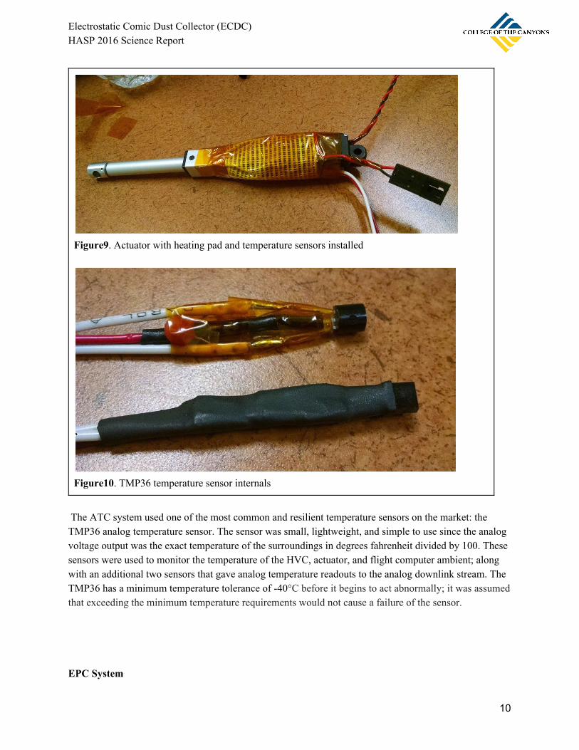
Figure9. Actuator with heating pad and temperature sensors installed
Figure10. TMP36 temperature sensor internals
The ATC system used one of the most common and resilient temperature sensors on the market: the TMP36 analog temperature sensor. The sensor was small, lightweight, and simple to use since the analog voltage output was the exact temperature of the surroundings in degrees fahrenheit divided by 100. These sensors were used to monitor the temperature of the HVC, actuator, and flight computer ambient; along with an additional two sensors that gave analog temperature readouts to the analog downlink stream. The TMP36 has a minimum temperature tolerance of -40°C before it begins to act abnormally; it was assumed that exceeding the minimum temperature requirements would not cause a failure of the sensor. EPC System
10

Electrostatic Comic Dust Collector (ECDC) HASP 2016 Science Report
The EPC system proved to be both one of the most simple and most complicated systems on the payload. The machining needed to be done on soft polycarbonate without marring surfaces that could trap terrestrial contaminants that would become impossible to remove during clean room cleaning. The copper plates were machined out of a highly-conductive copper 101 alloy to avoid the electric resistance that would raise the amperage needed. This plate was given rounded edges with a slight radius to fit into a polycarbonate holder with milled pocket. The milled pocket was given a depth the same as the thickness of the copper plate to have it set flush in the assembly and avoid attracting particles to the sides of the plate. This assembly was secured using 4 nylon standoffs using a hex socket but to ensure a snug fit. The copper mesh was then cut to fit the profile of the collector lid and laid on top of the standoffs to be secured by 4 brass screws. The wiring of the collector required the use of a potting epoxy to create two wire feed-throughs into the bottom of the enclosure. Two holes were drilled in the two thickest boss extrusions to ensure that the epoxy had the most surface area to adhere to. The potting resin was originally bought to be used in a high voltage converter enclosure before the idea was scrapped. Therefore, the resin had a very low viscosity meant to fill any gap but proved troublesome for our new purposes. Once cured, the resin was found to hold strongly and created a good barrier against dust contaminants. The wires that were fed through were then attached to the copper mesh and copper collection plate. The wire that energized the mesh used a crimped connector that was screwed down using the brass screws to provide a strong connection point. The wire that energized the plate went through some trial and error before settling on a final design. Soldering proved too difficult since the thermal conductivity of the plate was so good, it would not be able to heat up to the temperatures required for soldering before the ambient room temperature stabilized the temperature. The solution that was devised was to tape the frayed high voltage wire to the plate directly and glue the plate into the holder with a two-part cement epoxy.
Figure11. Secured copper plate assembly in the test EPC enclosure
11

Electrostatic Comic Dust Collector (ECDC) HASP 2016 Science Report
Figure12. Copper plates polished to 100-microns and acrylic pouring mold
The enclosure also implemented a ~2.5 micron filter taped onto a hole in the enclosure to provide pressure stabilization. Since NASA considers a pressure vessel to be a hazard for flight, HASP gave the team a clever suggestion to use a nano-filter to equalize the pressure between ambient pressure and the pressure inside the enclosure. The small nano-filter allowed gas to flow through the enclosure but stopped dust particles of all sizes from contaminating the sample. This simple design allowed the team to avoid the hassle and risk of another HASP hazard onboard the payload and simplified the entire design process.
IV. Integration The most critical test that the payload had to undergo was the Thermal-vacuum test at CSBF headquarters in Palestine, TX for HASP validation and integration. The series of tests conducted at the integration facility in Palestine would determine if the ECDC payload was cleared for launch. During the first day of integration, the team brought in the disassembled payload after the journey and began work of piecing together all the main flight components. This first day was reserved entirely for getting the payload together and installing the flight computer with working software. On the second day, the team completed the assembly of the payload and completed the current consumption and mass tests in order to participate in the thermal-vacuum test. For the thermal-vacuum test, a test article of the cleaned EPC enclosure was
12
Electrostatic Comic Dust Collector (ECDC) HASP 2016 Science Report
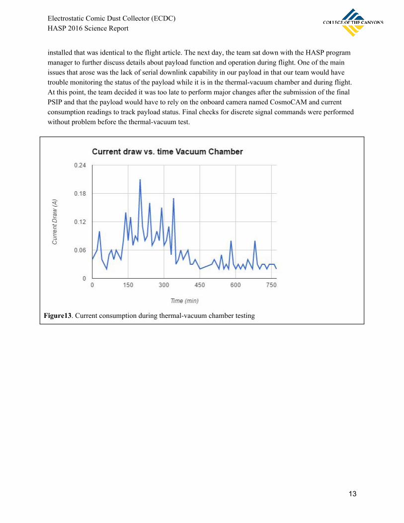
installed that was identical to the flight article. The next day, the team sat down with the HASP program manager to further discuss details about payload function and operation during flight. One of the main issues that arose was the lack of serial downlink capability in our payload in that our team would have trouble monitoring the status of the payload while it is in the thermal-vacuum chamber and during flight. At this point, the team decided it was too late to perform major changes after the submission of the final PSIP and that the payload would have to rely on the onboard camera named CosmoCAM and current consumption readings to track payload status. Final checks for discrete signal commands were performed without problem before the thermal-vacuum test.
Figure13. Current consumption during thermal-vacuum chamber testing
13

Electrostatic Comic Dust Collector (ECDC) HASP 2016 Science Report
Figure14. Thermal-vacuum chamber with HASP Figure15. Payload with test EPC enclosure
During thermal vacuum testing, current consumption was recorded by hand from the incoming HASP housekeeping stream and recorded by the team in a graph of current draw over time. As seen in the graph, current consumption was highest during the cold-test between 100 and 400 minutes since start of the data stream when the temperature was pulled down to -50°C. This showed the team that the active thermal control systems were active and warming the motor to prevent freezing. During the hot-test in the time period between 400 and 700 minutes, the temperature was then pulled up to +50°C. There were a few current spikes that were expected when the discrete signals were sent to activate the linear actuator. The EPC enclosure was opened and closed twice during the hot-test and the cold-test with success in all 4 discrete signal tests. After the thermal-vacuum test, the test EPC enclosure was swapped for the flight EPC enclosure that had been cleaned at the CSUN cleanrooms and identical to the test article used in testing. After a final inspection by the team, the decision was made that the payload was prepared for flight and was handed over to HASP personnel with flight certification complete.
V. Flight Once HASP officials announced the start of CSBF launch operations at Ft. Sumner NM for the launch of HASP 2016, the ECDC team was quickly organized to take timed shifts to monitor the launch status. During this time, classes had already started at College of The Canyons so nobody was able to make it to the flight-line to perform last-minute tests on the payload in preparation for flight. A total of 3 people from the team manned shifts during flight preparations to maintain communications with HASP officials and team members from other universities for feedback.
14

Electrostatic Comic Dust Collector (ECDC) HASP 2016 Science Report
Figure16. ECDC payload in view of CosmoCAM during flight
The team’s main source of payload status monitoring during flight was the current fluctuations recorded by the HASP system housekeeping data tables. These data tables were updated in a near-live data stream that could be accessed by anyone on the LSU HASP webpage. This data was closely monitored by members of the team throughout the entire flight with the exception of the power shutdown that occurred just prior to nightfall. One of the main status-monitoring streams that needed to be watched was the CosmoCAM video stream that was provided for the flight by the CSBF team. In an unfortunate turn of events, the camera failed to send a video feed down after about half an hour into the launch of the platform. After a while of dead signal, the ECDC team contacted the HASP officials for a status update on whether or not CosmoCAM would come back online. The answer was that the camera was likely not going to come back online for the duration of the flight and that alternative forms of status-monitoring had to be utilized.
15
Electrostatic Comic Dust Collector (ECDC) HASP 2016 Science Report
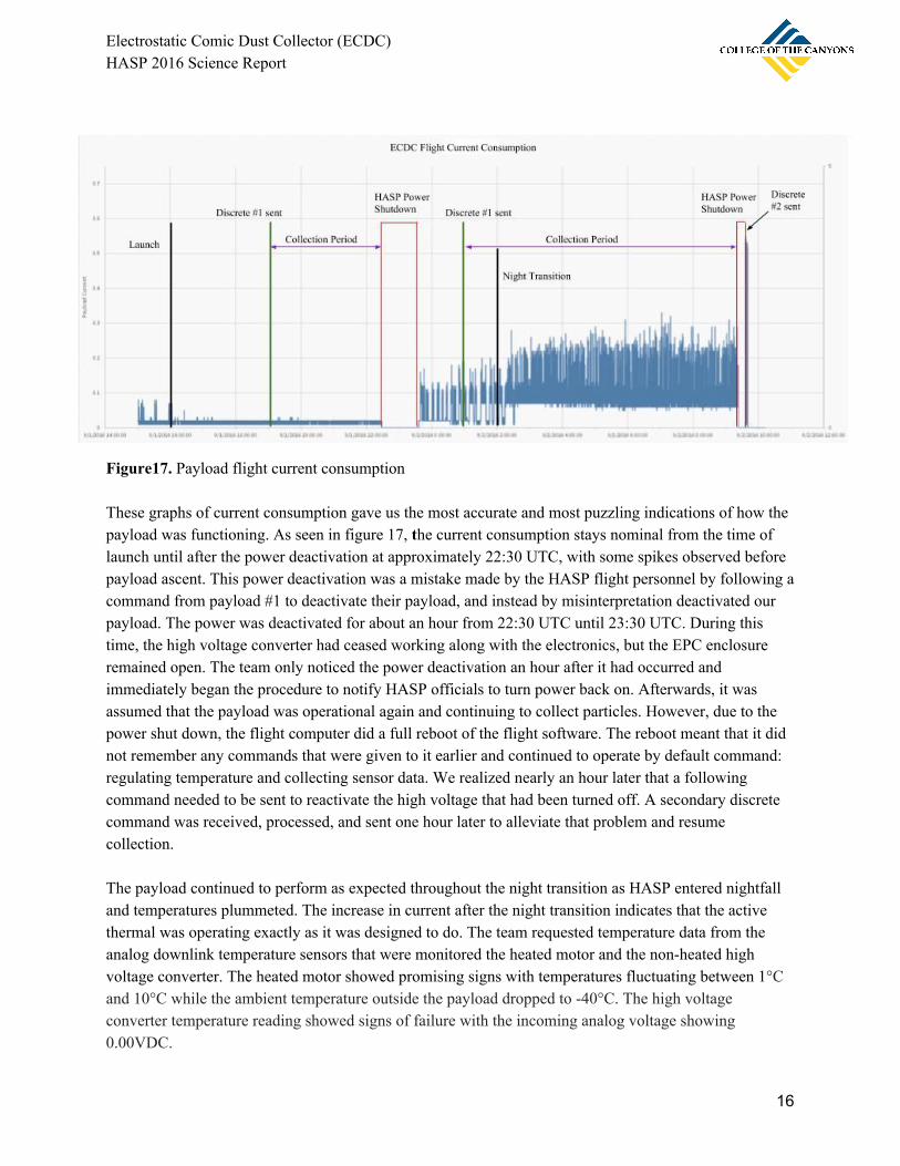
Figure17. Payload flight current consumption These graphs of current consumption gave us the most accurate and most puzzling indications of how the payload was functioning. As seen in figure 17, the current consumption stays nominal from the time of launch until after the power deactivation at approximately 22:30 UTC, with some spikes observed before payload ascent. This power deactivation was a mistake made by the HASP flight personnel by following a command from payload #1 to deactivate their payload, and instead by misinterpretation deactivated our payload. The power was deactivated for about an hour from 22:30 UTC until 23:30 UTC. During this time, the high voltage converter had ceased working along with the electronics, but the EPC enclosure remained open. The team only noticed the power deactivation an hour after it had occurred and immediately began the procedure to notify HASP officials to turn power back on. Afterwards, it was assumed that the payload was operational again and continuing to collect particles. However, due to the power shut down, the flight computer did a full reboot of the flight software. The reboot meant that it did not remember any commands that were given to it earlier and continued to operate by default command: regulating temperature and collecting sensor data. We realized nearly an hour later that a following command needed to be sent to reactivate the high voltage that had been turned off. A secondary discrete command was received, processed, and sent one hour later to alleviate that problem and resume collection. The payload continued to perform as expected throughout the night transition as HASP entered nightfall and temperatures plummeted. The increase in current after the night transition indicates that the active thermal was operating exactly as it was designed to do. The team requested temperature data from the analog downlink temperature sensors that were monitored the heated motor and the non-heated high voltage converter. The heated motor showed promising signs with temperatures fluctuating between 1°C and 10°C while the ambient temperature outside the payload dropped to -40°C. The high voltage converter temperature reading showed signs of failure with the incoming analog voltage showing 0.00VDC.
16
Electrostatic Comic Dust Collector (ECDC) HASP 2016 Science Report
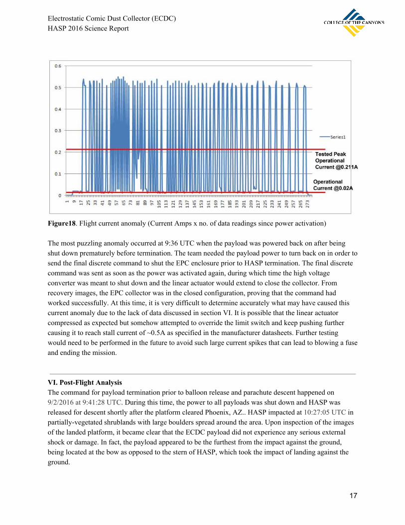
Figure18. Flight current anomaly (Current Amps x no. of data readings since power activation) The most puzzling anomaly occurred at 9:36 UTC when the payload was powered back on after being shut down prematurely before termination. The team needed the payload power to turn back on in order to send the final discrete command to shut the EPC enclosure prior to HASP termination. The final discrete command was sent as soon as the power was activated again, during which time the high voltage converter was meant to shut down and the linear actuator would extend to close the collector. From recovery images, the EPC collector was in the closed configuration, proving that the command had worked successfully. At this time, it is very difficult to determine accurately what may have caused this current anomaly due to the lack of data discussed in section VI. It is possible that the linear actuator compressed as expected but somehow attempted to override the limit switch and keep pushing further causing it to reach stall current of ~0.5A as specified in the manufacturer datasheets. Further testing would need to be performed in the future to avoid such large current spikes that can lead to blowing a fuse and ending the mission.
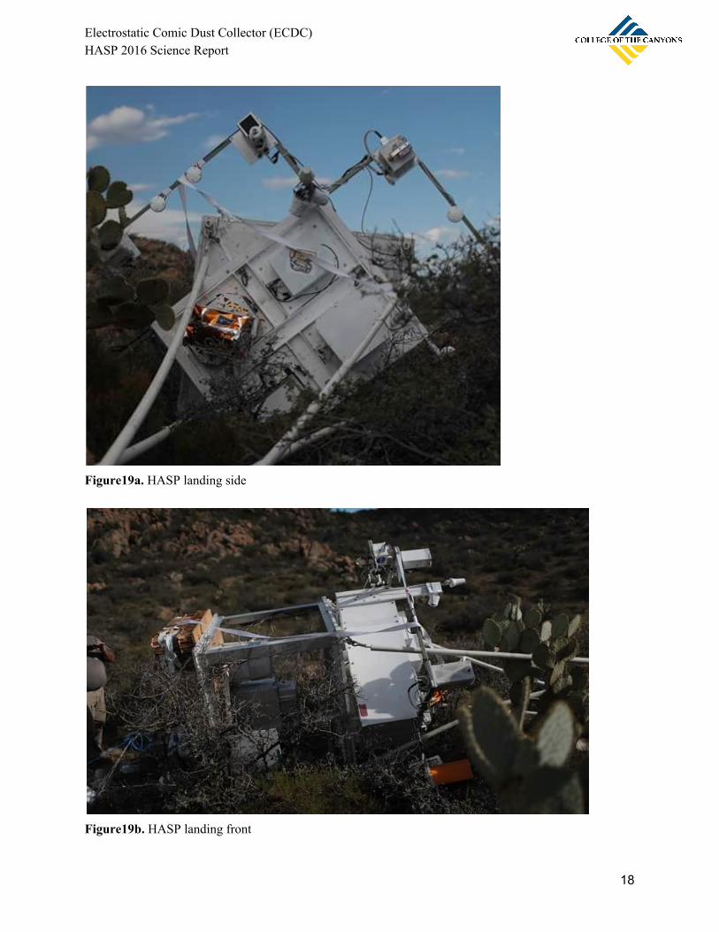
VI. Post-Flight Analysis The command for payload termination prior to balloon release and parachute descent happened on 9/2/2016 at 9:41:28 UTC. During this time, the power to all payloads was shut down and HASP was released for descent shortly after the platform cleared Phoenix, AZ.. HASP impacted at 10:27:05 UTC in partially-vegetated shrublands with large boulders spread around the area. Upon inspection of the images of the landed platform, it became clear that the ECDC payload did not experience any serious external shock or damage. In fact, the payload appeared to be the furthest from the impact against the ground, being located at the bow as opposed to the stern of HASP, which took the impact of landing against the ground.
17
Electrostatic Comic Dust Collector (ECDC) HASP 2016 Science Report
Figure19a. HASP landing side
Figure19b. HASP landing front
18

Electrostatic Comic Dust Collector (ECDC) HASP 2016 Science Report
When the payload returned back to the college, the anticipation was met with a set of good news and bad news. The good news was that the HASP personnel that were asked to remove the flight EPC enclosure with the collection apparatus had done a phenomenal job with the removal of the enclosure as specified in the FLOP. The enclosure had the proper fasteners installed that kept the lid shut in the process of moving it from the landing site to the clean room. In addition, the enclosure had been wrapped in the antistatic bag and bubble wrap with care and attention to avoid the sample breaking during shipping back to California. The state of the rest of the payload proved to be less than promising. The issues began to arise when the USB interface cable was plugged in, giving the payload power for the first time since flight. The status LED remained off even though the computer showed that the flight computer was functional. When the serial interface with the computer was checked, it showed that the program was stuck in opening a new data logging file. The flight computer was taken out of the payload and the problem was immediately visible. The right-hand row of pins of the flight computer were completely disconnected and the left-hand row of pins were partially disconnected and bent to a 30 degree angle.
Figure20a. Bent flight computer pins post-landing Figure20b. Disconnected pins post-landing
The right-hand pins were responsible for analog sensor processing, reset, and sensor power. The left-hand pins that remained connected were mainly responsible for communication between shields. This design flaw could have been easily fixed using a single zip-tie across the stack of shields in order to prevent disconnection.
19

Electrostatic Comic Dust Collector (ECDC) HASP 2016 Science Report
VII. Results Most of the science collected on this mission was unable to be uncovered or analyzed for use in this HASP 2016 science report due to multiple reasons. A single most contributing factor being the situation that developed at the CSUN clean rooms after the return of the sample in preparation for particle analysis. In early September, a biohazard leak had occurred in one of the adjacent labs and caused the entire building to be closed on lockdown from mid-September until late November. This issue had crippled the project since september and caused the team’s most productive months before December to come to a standstill. Once the sample had arrived back to College of The Canyons in early December, the logistics of organizing the team during the busiest part of the semester proved to be too great. For continued research during the months of waiting, computer simulation models were created to better fully understand the dynamic patterns of high voltage behavior in a low-pressure environment. Dealing with voltages as high as 10kV can be hazardous to any form of electronics if it were to discharge during flight. Calculations were made without the use of simulations in the design phase before flight to ensure that such discharge would not occur.
20
Electrostatic Comic Dust Collector (ECDC) HASP 2016 Science Report
Computer Models and Simulations
Figure21a. Voltage potential model Figure21b. Electric field strength model
Figure21c. Electric field gradient model w/ mesh Figure21d. Electric field strength model w/ mesh
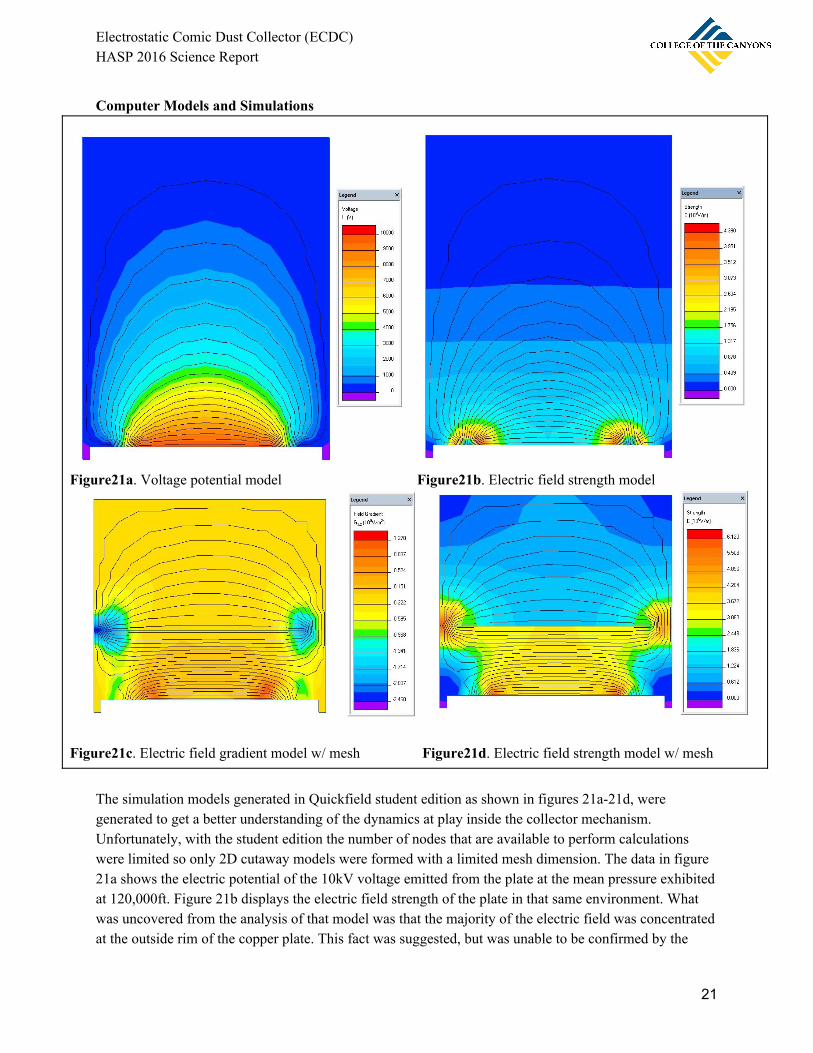
The simulation models generated in Quickfield student edition as shown in figures 21a-21d, were generated to get a better understanding of the dynamics at play inside the collector mechanism. Unfortunately, with the student edition the number of nodes that are available to perform calculations were limited so only 2D cutaway models were formed with a limited mesh dimension. The data in figure 21a shows the electric potential of the 10kV voltage emitted from the plate at the mean pressure exhibited at 120,000ft. Figure 21b displays the electric field strength of the plate in that same environment. What was uncovered from the analysis of that model was that the majority of the electric field was concentrated at the outside rim of the copper plate. This fact was suggested, but was unable to be confirmed by the
21
Electrostatic Comic Dust Collector (ECDC) HASP 2016 Science Report
team during the design phase. The high voltage electric breakdown concentrates around the sharpest points of an electrode where the electrons are more easily able to create an electron avalanche and ionize the air around that vicinity. This relatively higher electric field will in that case attract more oppositely charged particles that were previously ionized by the copper mesh. These electric field emitting regions gave the scientific analysis team a better prediction for where the particles may have accumulated at the greatest concentrations. Figures 21c and 21d were then modeled with the thin copper mesh included, displaying the field gradient and electric field strength. The field gradient was able to give us a good overall representation of where the negative charge was produced and where it was collected on the relatively positive plate. The field strength model was able to illustrate how the particles would travel once they have been ionized by following the electric field form the mesh to the collection plate. One major concern in this was since the design called for the potential between the mesh and plate to be so high at such low pressures, arcing would occur between the two electrodes. Paschen curves needed to be analyzed and showed that with a spacing of 2.5cm at ~0.01atm and 10kV potential, arcing would not occur since that point was below the line of voltage breakdown.
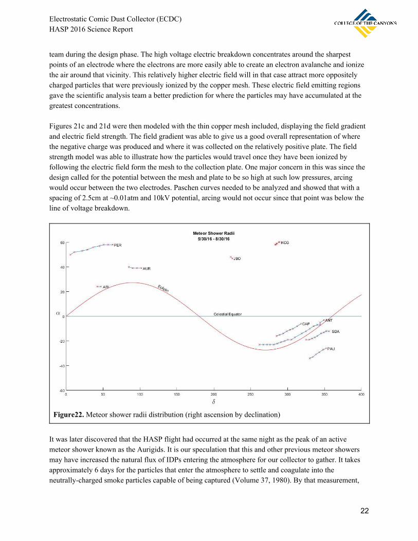
Figure22. Meteor shower radii distribution (right ascension by declination)
It was later discovered that the HASP flight had occurred at the same night as the peak of an active meteor shower known as the Aurigids. It is our speculation that this and other previous meteor showers may have increased the natural flux of IDPs entering the atmosphere for our collector to gather. It takes approximately 6 days for the particles that enter the atmosphere to settle and coagulate into the neutrally-charged smoke particles capable of being captured (Volume 37, 1980). By that measurement,
22

Electrostatic Comic Dust Collector (ECDC) HASP 2016 Science Report
the particles that would have been collected were from the very beginning of the weak meteor shower. Since HASP was flying at approximately 34N and 112W, the radii from the meteor shower would have been very close to the flight profile. Future work in this field would be able to show how the probabilities of the origin from which the particles may have been collected. This probability could be backed up or even proved through compositional analysis of the particle if the predicted parent-object composition is known. Sample Retrieval
Figure23a. Flown copper plate collector during Figure23b. Acrylic embedding of copper plate in custom analysis mold
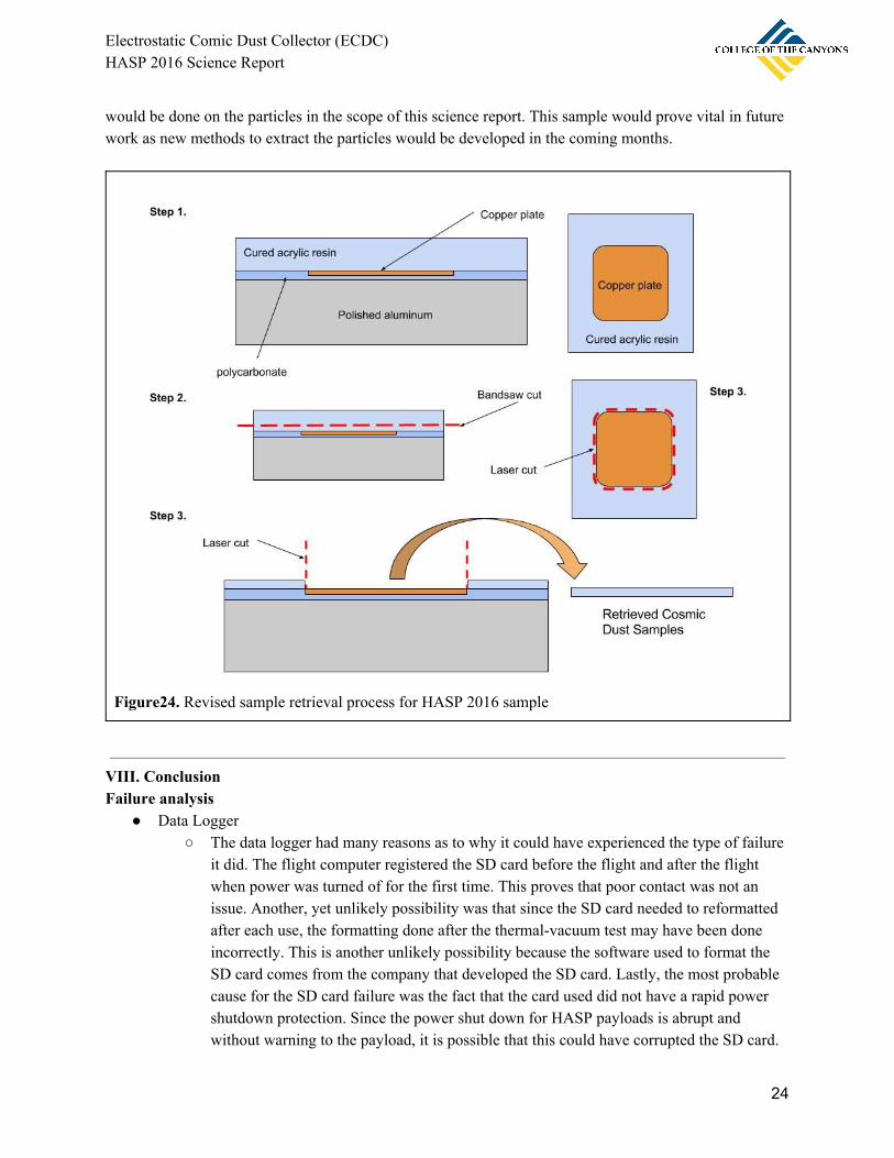
The analysis of the sampled copper plate proved to the biggest drawback and failure of the entire mission. When the sample was retrieved from the CSUN clean room, some high-powered optical microscopy time was planned for the following Friday at the College of The Canyons labs. Before the microscope appointment, the sample was taken out of the casting mold without problem. However, a deeply rooted fear that the acrylic resin would bond to the polycarbonate shell was confirmed. The sample on the copper plate was lodged in between two fused layers of acrylic and polycarbonate with no way of retrieving the sample with the method described before. A new method was developed by the team the next day that could be used to retrieve the needed sample from the polycarbonate. This method involved first using a bandsaw to cut away a slice of the top portion acrylic that does not contain particles. Then, once the acrylic is ~0.25 inches thick, a laser cutter would be used to cut the acrylic from the copper plate. This method would be risky since some vital particles could be burned away if they lie on the path of the laser, which by chance is the area with the greatest probability of finding particles. It was eventually decided that to avoid risking the sample, no analysis
23
Electrostatic Comic Dust Collector (ECDC) HASP 2016 Science Report
would be done on the particles in the scope of this science report. This sample would prove vital in future work as new methods to extract the particles would be developed in the coming months.
Figure24. Revised sample retrieval process for HASP 2016 sample
VIII. Conclusion Failure analysis
● Data Logger ○ The data logger had many reasons as to why it could have experienced the type of failure
it did. The flight computer registered the SD card before the flight and after the flight when power was turned of for the first time. This proves that poor contact was not an issue. Another, yet unlikely possibility was that since the SD card needed to reformatted after each use, the formatting done after the thermal-vacuum test may have been done incorrectly. This is another unlikely possibility because the software used to format the SD card comes from the company that developed the SD card. Lastly, the most probable cause for the SD card failure was the fact that the card used did not have a rapid power shutdown protection. Since the power shut down for HASP payloads is abrupt and without warning to the payload, it is possible that this could have corrupted the SD card.
24

Electrostatic Comic Dust Collector (ECDC) HASP 2016 Science Report
This problem could be alleviated by running some tests on various SD cards with the shutdown protection circuitry built into the chip.
● Flight Computer
○ The flight computer pin-disconnection issue was a foreseen issue that could have been easily addressed, but was forgotten during the final assembly of the payload during integration. What could have been done was to attach a set of zip-ties across the PCB stack to prevent them from becoming detached. A full and better-detailed list of procedures would need to have been written to avoid forgetting simple steps like these.
● Temperature Sensor
○ The temperature sensors, despite having a reliable minimal temperature constraint, have internal circuitry that is not suitable for the environment they encounter during flight. Robust temperature sensors need to be added capable of enduring the absolute minimum temperatures expected during flight. This can be done more effectively with thermistors since they do not rely on the delicate silicon-based circuitry that both digital and analog temperature sensors use.
● Acrylic-embedded collection plate sample
○ New materials that do not bond to the acrylic sample such as PTFE or Nylon could be used to secure the copper plate instead of polycarbonate. Polycarbonate is chemically very similar to acrylic and therefore the two are very easy to bond together. This problem was hypothesized but no tests were run due to the schedule that needed to be followed in order to meet project deadlines. More time for testing of procedures would need to be set aside in the future to avoid mishaps such as this.
Future work & Lessons Learned Engineering
● Thermistors instead of discrete analog temperature sensors ● Allow time for testing of each individual flight component - vacuum, cryogenic, and oven tests
should be performed prior to the thermal-vacuum test during integration ● Include serial uplink and downlink capabilities ● Filtered power supply and analog signals ● Design a printed circuit board for power management ● Secure internal electronics to withstand stronger shocks ● Flight data backup recording systems - multiple data logging systems are needed in order to make
sure that important flight data gets preserved safely. Science
● A better scientific analysis plan with detailed procedures and fail-safes ● Contact previous HASP teams and cosmic dust researchers to gain advice knowledge from their
experiences ● Research better materials that do not bond to acrylic resins and have excellent thermal and
electrical insulating properties.
25

Electrostatic Comic Dust Collector (ECDC) HASP 2016 Science Report
● Contribute more research to the analysis of the particles rather than the engineering of the payload ● Recruit more investigators and scientists to the student team; pulling more from the geology,
astronomy, and chemistry majors. Project/Team Management
● Keep a common timestamped log of all flight and launch operations that is contributed to by every team member participating in flight operations
● Assign more leadership positions to spread the workload ● Create a work-schedule to help advisors manage their hours months in advance
IX. Team Management Demographics
Name Gender Ethnicity Race Student Status Disability that limits a life activity
Daniel Tikhomirov
Male Non-Hispanic White/Caucasian Undergraduate No
Nicholas Kadsjono
Male Non-Hispanic Asian Undergraduate No
Mindy Saylors Female Non-Hispanic White/Caucasian Undergraduate No
Patrick Gagnon Male Non-Hispanic White/Caucasian Undergraduate No
Jason Monsalve Male Hispanic White/Caucasian Undergraduate No
Wyatt Kurumiya Male Non-Hispanic Asian Undergraduate No
Jayme Gimenez Female Hispanic White/Caucasian Undergraduate No
Savanna Rousello Female Non-Hispanic White/Caucasian Undergraduate No
Irfan Zaman Male Non-Hispanic Asian Undergraduate No
Julian Drake Male Non-Hispanic African-American/ Black
Undergraduate No
David Al-Nemri Male Non-Hispanic Asian Undergraduate No
Justin Hill Male Non-Hispanic White/Caucasian Undergraduate No
Scott Sebesta Male Non-Hispanic White/Caucasian Undergraduate No
Additional information:
26

Electrostatic Comic Dust Collector (ECDC) HASP 2016 Science Report
Name Major Role Status
Daniel Tikhomirov
Aerospace Engineering
Project Manager, Principal Investigator, Chief Engineer
Transferring from College of The Canyons
Nicholas Kadsjono
Electrical Engineering
EPC systems lead Transferring from College of The Canyons
Mindy Saylors Electrical Engineering
Power management Lead Transferred to University of California Irvine
Patrick Gagnon Aerospace Engineering
Mechanical systems lead Transferring from College of The Canyons
Jason Monsalve Computer Science Flight systems lead Transferring from College of The Canyons
Wyatt Kurumiya Physics Thermal management lead Transferring from College of The Canyons
Jayme Gimenez Chemistry & Computer Science
Flight systems engineer
Transferring from College of The Canyons
Savanna Rousello Chemistry EPC systems engineer Transferred to California State University Long Beach
Irfan Zaman Electrical Engineering
Power management engineer
Transferring from College of The Canyons
Julian Drake Physics Thermal management engineer
Transferring from College of The Canyons
David Al-Nemri Mathematics & Physics
EPC systems engineer Transferred to University of California Los Angeles
Justin Hill Aerospace Engineering
Mechanical systems engineer
Transferred to Cal Poly Pomona
Scott Sebesta Chemistry Mechanical systems engineer
Transferring from College of The Canyons
X. References
27

Electrostatic Comic Dust Collector (ECDC) HASP 2016 Science Report
1. Nelson, J. P. (1981, April). High-Altitude Considerations for Electrical Power Systems and Components. IEEE, 1A (20), 2nd ser.
2. Hunten, D. M., Turco, R. P., & Toon, O. B. (1980, June). Smoke and Dust Particles of Meteoric
Origin in the Mesosphere and Stratosphere. Journal of The Atmospheric Sciences, 37 , 1342-1357.
3. "Cosmic Dust Webpage." - Cosmic Dust from the Stratosphere . Learning & Scholarly Technologies, 1998. Web. 7 Oct. 2015. <https://catalyst.uw.edu/workspace/idp/40208/285085>.
4. "Cosmic Dust Webpage - Astrobiology." - Astrobiology . Learning & Scholarly Technologies,
1998. Web. 7 Oct. 2015. <https://catalyst.uw.edu/workspace/idp/40208/285083>.
5. Matrajt, G., & Brownlee, D. E. (2006, August 28). Acrylic embedding of Stardust particles encased in aerogel. Meteoritics & Planetary Science, 41 (11), 1715-1720.
28