electronics · u- boost, list $39.95 ... your heads the quick two minute spot check as shown above...
TRANSCRIPT

Electronics World SPEtlE'-. DIRECT - READING INSTRUMENTS
EQuwME.4l: SIGNAL - GENERATING EQUIPMENT
iSSOE CATHODE -RAY OSCILLOSCOPES
AUGUST, 1963 50 CENTS
THE INSTRUMENT CALIBRATION & REPAIR TECHNICIAN DETECTION OF NUCLEAR
RADIATION BY SEMICONDUCTORS CALIBRATING TEST EQUIPMENT ACCURATE
AUDIO FREQUENCY MEASUREMENT 1963 DIRECTORY OF TEST EQUIPMENT KITS
bonus insert: Color Codes Chart
V-I3 P IYtiV1Iti J10 8b MS 0£1
N61Oafl lore 9b0 b SO£A;Vp
,..s á 4

Where You Train Is As Important As Your
Decision To Train Electronics is a growing and expanding industry. That's why so many ambitious men are deciding to train for ca- reers in this exciting field. They recognize the opportu- nities to advance and pros- per. But, where a man trains and how the school of his choice teaches Electronics
. how it encourages him to reach his goals and realize his ihitions ... is most important to his success.
is is a fast changing world. A school offering Electronics arses must keep pace. That's why NRI -with nearly 50 years specialized experience -now offers nine choices of training hin the one field of Electronics. Select the course of most erest to you and receive the kind of home -study training that -pares you for a specialized career. NRI's large staff of -)cialists is always on the job keeping course material up -to- te . .. helping you earn your way while training ... assisting
with job placement when ready. In short, whatever branch Electronics you select, NRI is qualified through e` °'T` °s`°
owledge and experience to help you grow.
ECIAL TRAINING EQUIPMENT INCLUDED I "learn by practice"
-:thod is the time -proved y to learn easier, faster, tter. Most NRI courses in- ide -at no extra cost -spe- 1 training equipment to give p and laboratory experi- e in your own home. All
uipment is yours to keep. Projects you build, experi- nts you perform, make íl lessons come to life. Complex subjects become interest- , easy to grasp. Your first projects are measuring voltage
d current in circuits you build yourself. You use a Vacuum be Voltmeter which you construct. Later on, you progress o more involved experiments. If you like working with your nds, you'll enjoy learning Electronics with NRI.
lE PROVEN WAY TO BETTER PAY st of all, NRI provides training right in your own home and your spare time. No time wasted getting to school. You fit dy hours to your own schedule. You go as fast or as slow you like. Check the training of most interest to you; cut out
mail the postage -free card now. Read about Electronics portunities, NRI courses, the NRI trial plan, convenient ms.
America "s Oldest and Largest Radio -TV
Electronics Home -Study School
Pick the ELECTRONICS
CAREER You Want
2
3
4
5
6
8
9
RADIO AND TELEVISION SERVICING
Learn to service AM -FM Radios, black and white and color TV sets, Stereo Hi -Fi, PA systems, etc. A profit- able, interesting field for part -time or full-time business of your own.
INDUSTRIAL -MILITARY ELECTRONICS
Learn Principles, Practices, Maintenance of Elec- tronic equipment used today in business, industry, defense. Covers Electronic controls and measurement, computers, servos, telemetry, multiplexing, many other subjects.
COMPLETE COMMUNICATIONS
A comprehensive training course for men seeking careers operating and maintaining transmitting equip- ment in Radio -TV Broadcasting or mobile, marine, aviation communications. Prepares you for FCC License.
FCC LICENSE!
Prepares you quickly for First Class License exams. Every communications station must have one or more FCC -licensed operators. Also valuable for Service Technicians. You train at home.
BASIC ELECTIRONICS
An abbreviated, 26- lesson course covering Automa- tion- Electronics, Radio -Television language, compon- ents and principles. Ideal for salesmen, hobbyists and others who find it valuable to be familiar with the fundamentals of this fast-growing industry.
MATH FOR ELECTRONICS
A short course package of five carefully prepared texts that take you from basic arithmetic review through graphs and electronic formulas. Quick, com- plete and low in cost.
AVIATION COMMUNICATIONS
For men who want careers working with and around planes. Covers direction finders, ranges, markers, loran, shoran, radar, landing systems, transmitters. Prepares you for FCC License exams.
MARINE COMMUNICATIONS
Shipboard transmitting equipment, direction finders, depth indicators, radar are all covered in this course. You prepare for your First Class Radiotelephone Li- cense with Radar Endorsement.
MOBILE COMMUNICATIONS
Training in installation and maintenance of mobile equipment and associated base stations like those used by fire and police, taxi companies, etc. Prepares you for First Class FCC License exams.
MAIL POSTAGE -FREE CARD NOW

11,
Add 15 miles to UHF reception range
First All Channel UHF Booster
The fabulous new Blonder- Tongue U -Boost adds up to 15 miles to the UHF reception range. Homes formerly out of the range of UHF can now receive sharp, clear reception. The U -Boost will also clean up and improve fuzzy TV pictures in weak UHF signal areas, making them sharp and clear. The U -Boost (gain 10 db) triples the antenna signal voltage. Teamed up with any UHF converter, or added to an all - channel receiver, the U -Boost improves reception on any UHF channel 14 to 83. Just a turn of the dial pinpoints the desired channel and brings it in sharp and clear. The TV picture quality is always excellent with the U- Boost, since it amplifies the signals before conversion, delivering the best signal -to -noise ratio. Installation of the U -Boost is easy. It has an AC convenience
engineered and manufactured by
Blonder -Tongue U -BOOST
receptacle; patented 300 ohm stripless terminals make it a cinch to connect twin lead without stripping or splicing. The modern U -Boost styling matches the new Blonder -Tongue UHF converters. U- Boost, List $39.95
BLONDER -TONGUE UHF CONVERTERS, PERFORMANCE- PROVED 2,000,000 TIMES
Blonder -Tongue 99 -S - all- channel UHF converter for prime signal areas List $27.95
Blonder -Tongue BTU- 2T -alI channel converter with 5 to 8 db increase in signal power. For weak signal areas List $44.95
Look to the leader in UHF. See your Blonder -Tongue distributor.
BLONDER TONGUE 9 Alling St.. Newark.2 N. J.
Canadian Div.: Benco Television Assoc., Ltd., Toronto, Ont. /home TV accessories closed circuit TV community TV UHF converters master TV
August, 1963 CIRCLE NO. 105 ON READER SERVICE PAGE 4

e
Original Equipment
Designers
-.c , p 1
Choose Tubes from Complete Stocks at Local RCA Distributor
Just call. And watch your RCA Industrial Tube Distributor perform on any of your OEM or replacement needs for RCA tubes. He carries large inventories. Latest tube types available immediately can help you meet emergency lab requirements, help keep your production schedules rolling.
He can also provide practical applica- tion data. When you need it, just ask him.
For name and address of your local Heights 94, Mass.: 80 "A" St.. Hill Ohio: 1621 Euclio Ave.. CHerry 1
7711 State Line, EMerson 1-6462;
2:
So. Get to know your local RCA Indus- trial Tube Distributor...for priority service on quality RCA tubes for color TV, black - and -white TV, AM -FM radio, Hi -Fi, Phono- graphs, and industrial and communica- tions equipment of every description.
RCA ELECTRONIC COMPONENTS AND DEVICES, HARRISON, N. J.
\r is
distributor write or call your nearest RCA Distributor Products Sales Office -New York, N. Y.: 36 W. 49th St., MUrray H 9 -7200, Needham
crest 4 -8480; Washington 7, D. C.: 1725 "K" St.. S.W.. FEderal 7 -8500, Atlanta, Ga.: 134 Peachtree St., N.W., JAckson 1 -7703; Cleveland, -3450; Chicago, Ill.: Merchandise Mart, 467 -5900; Dallas 7, Texas: 7901 Carpenter Freeway, MElrose 1 -3050; Kansas City 14, Ma.:
Los Angeles 22, Cal.: 6801 E. Washington Blvd., RAymond 3 -8361.
The Most Trusted Name ii Electronics
ELECTRONICS WORLD
EkctroiiisWoiid CONTENTS AUGUST 1963 / VOL. 70 NO. 2
23 Direct -Reading Instruments Frederick Van Veen t (,,vr,vul Radio Conrparn, u leading nannlar-
i. ., ';11+! r>1 lia'it- reading instruments, give, an irullr.tr .,, .
u ifll rlpor t ,fn the l'eTY l',t egrtipnugu and nu,asoring (rchnigue:.
27
28
30
On Our Cover
The Calibration & Repair Technician G. Gedney & F. Winterburg
Naval Observatory Time Signals H. Charles Wood
31 Signal- Generating Equipment Howard L. Roberts- t flac Il,vlL e ft- Packard Co., prominent in the field of ,oral- _erur,fíng ertnipraent. ,li.rrrsse.a all tYpe.a of devices employed to
g,/ovate test i_n,rls Iron 1+11,11 the audio range up through micratrrrces.
35 Color Codes Chart
37 Meter Range- Extension Nomogram A. L. Teubner
38 Decibel Table
39 Detection of Nuclear Radiation by Semiconductors H. Renne
43 Calibrating Test Equipment Walter H. Buchsbaum
46 Accurate Audio Frequency Measurement Aaron W. Edwards
48 The Operational Amplifier (Part 2) Jack E. Frecker
50 Cathode -Ray Oscilloscopes Edward K. Marrie nl the l Fairchild- /)1r11orU 1.1,1+11 nturies, prudm rv.a of the first commercial oscilloscope in 19: ;2, describes the latest advances in the design and performance of present -day instruments.
54 1963 Directory of Kit Test Equipment I f,ruplltl ii,ItII Ht fill tc,t equipment actable in kit form. Over 200
r1+ igni divided info 2v) categories according to function, are covered.
69 FCC Establishes Fees for Radio Licenses
77 Simple Hum -Bucking Circuit G. R. Gilbert
6 For the Record (Editorial) W. A. Stocklin peelrtl Issue
12 EW Lab Tested Slut re Model 5611 Lovelier Microphone Scott :fiel -8 Stereo Tuner
66 Semiconductor Seminar John Frye
78 Test Equipment Product Report Kr I llodel H li -.SI I Ill , aereo Signal Generator I,sociaterd Research _,, eil lleiolunnu,ler
Sencore CItI25 Cathode -Ray Tube 'fester
MONTHLY FEATURES Coming Next Month Letters from Our Readers Reader Service Page
August, 1963
4 Electronic Crosswords 8 Radio & TV News
19 New Products & Literature Copyright S 1963 by ZitfDavis Publishing Company. All rights reserved.
71 81 85
.,r iY l wi(1
SPCCIQU\PfN} 5'
THIS MONTH'S COVER sym- bolizes the important role played by test equipment on the service bench, on the production line, and in our laboratories. Special articles in this Test Equipment Issue survey the entire field with coverage of direct -reading instruments, signal- generat- ing devices, cathode -ray os- cilloscopes, and test- equip- ment kits. Other articles on the calibration of test equip- ment and role of technicians responsible for checking and repair are also included. For a description of the spe- cific pieces of equipment shown on our cover, see the Cover Story on page 27.
Publisher PHILLIP T. HEFFERNAN
Editor WM. A. STOCKLIN
Technical Editor MILTON S. SNITZER
Service Editor SIDNEY C. SILVER
Associate Editor P. B. HOEFER
Editorial Consultant OLIVER READ
Industrial Consultant WALTER H. BUCHSBAUM
Art Editor MILTON BERWIN
Art and Drafting Dept. J. A. GOLANEK
Advertising Sales Manager LAWRENCE SPORN
Advertising Service Manage, ARDYS C. MORAN
3

THAT MUSIC SOUNDS
TERRIBLE. THE TAPE MUST BE WORN OUT.
NORTRON/CS SAYS "TAPE DOESN T
WEAR OUT-- -
®(
AidÌ SPOT CHECK HEADS IN
2 MINUTES ...Look for A. Grooves or
spots on Surface.
8. This verti. cal black line divid- ing either pole piece. BLT,
TAPE HEADS DO! SURE ENOUGH, OUR HEADS HAVE A BLACK VERTICAL LINE THROUGH THE POLE PIECES. I BETTER SEE OUR DEALER TOMORROW
BOY, THESE HEADS ARE WORN.WE CAN REPUE THEM OR YOU CAN DO-IT- YOURSELF. NORTRON /CS HEADS AND "QUIK-KITS" HAVE COMPLETE EASY -TO-FOLLOW INSTRUCTIONS.
JUST A MINUTE, I'LL AZIMUTH THIS NEW HEAD AND WE'RE IN BUSINESS.
WHAT BI G D /FFERENCE.
THE MUSIC SOUNDS EVEN BETTER THAN WHEN THE RECORDER WAS
NEW.
/ HAVE YOU CHECKED YOUR HEADS LATELY?
Get the most from your investment in tape equipment. Be certain that head wear is not causing you to lose the clean, crisp sound which only tape can give you. Give your heads the quick two minute spot check as shown above - or, have your Hi -Fi dealer, Radio -TV serviceman or camera store check your heads for wear.
Insist on NORTRONICS replacement heads and "Quik -Kit" mounting hardware; both correctly matched to your recorder.
"Music sounds best on tape - Tape sounds best with Nortronics heads"
812; 10th Ave. North Minneapolis 27, Minn.
rWrite today for your FREE copy of NORTRONICS
Tape Head Replacement Guide.
Name
Address
City State
LI own a Model tape recorder
CIRCLE NO. 129 ON READER SERVICE PAGE 4
COMING NEXT
MONTH
ELECTRONIC ANESTHESIA Although the technique is far from per- fected, interesting research and develop- ment work is underway as this survey indicates.
THIN LOUDSPEAKER SYSTEMS The various methods being used to make hi -fi speakers and their enclosures as shallow as possible are evaluated and described in George Augspurger's article. Available commercial thin loudspeaker units are illustrated.
LOW -PASS AUDIO FILTERS FOR INCREASED "TALK- POWER" The addition of this simple, low -cost device to the amateur phone transmitter will improve performance to a great ex- tent. The unit is easy to build from standard, readily available electronic parts.
ELECTRONICS FIELD ENGINEERS AROUND THE WORLD These specialists -in great demand -are trained to do the "impossible" in keep- ing military, government, and industrial equipment in top working condition at locations ranging from the arctic regions
- I:Itelii}ii(`s11or[tl
(
IAi'E.SLDE YNCHRONIff
to dense jungle areas -wherever elec- tronics equipment must be installed and kept in reliable operation.
TAPE -SLIDE SYNCHRONIZER A silicon -controlled switch is the "heart" of this compact device designed for the photography fan who wants to record a commentary on his slide on tape and then synchronize the picture with his talk.
FREQUENCY MULTIPLICATION AND DIVISION A survey of the techniques and circuits commonly found in such diverse units as frequency standards, counters, digital clocks, multiplex adapters, transmitters, and electronic organs. Practical applica- tions are also covered.
TRANSISTORS IN HI -FI: PANACEA OR PANDEMONIUM? Three top engineers from H. H. Scott discuss the conceptions and misconcep- tions prevalent in the industry regarding the role of transistors in high -fidelity audio equipment. This is the first article of a two -part series discussing this sub - ject in depth.
All these and many more interesting and informative articles will be yours in the SEPTEMBER issue of ELECTRONICS WORLD . . . on sale Aug. 15th.
ZIFF -DAVIS PUBLISHING COMPANY William B. Ziff Chairman of the Board (1946 -1953) William Ziff President W. Bradford Briggs Executive Vice President Hershel B. Sarbin Vice President and General Manager M. T. Birmingham, Jr. Vire President and Treasurer Robert P. Breeding Circulation Director Charles Housman Financial Vice President Stanley R. Greenfield Vice President Phillip T. Heffernan Vice President
ZIFF -DAVIS PUBLISHING COMPANY Editorial and Executive Offices One Park Avenue, New York 16, New York ORegon 9 -7200
MIDWESTERN and CIRCULATION OFFICE 434 South Wabash Avenue, Chicago 5, Illinois WAbash 2 -4911 Midwestern Advertising Manager, Gilbert J. Jorgenson
WESTERN OFFICE 9025 Wilshire Boulevard, Beverly Hills, California CRestview 4 -0265 Western Advertising Manager, Bud Dean
FOREIGN ADVERTISING REPRESENTATIVE D. A. Goodall Ltd., London, England
e,
HIGH PASTIME
FIDELIT1 ~^
- " - cULI,z,
Member Audit Bureau of
Circulations
Radio & TV News Radio News Radio -Electronic Engineering Trademarks Reg. U.S. Pat. Off.
SUBSCRIPTION SERVICE: All subscription correspondence should be addressed to Electronics World. Circu- lation Dept.. 434 South Wabash Ave., Chicago 5, Ill. Please allow at least six weeks for change of address. Include your old address as well as new -enclosing if possible an address label from a recent issue.
EDITORIAL CONTRIBUTIONS must be accompanied by return postage and will be handled with reasonable care; however publisher assumes no responsibility for return or safety of art work. photographs, or
manuscripts. ELECTRONICS WORLD is published monthly by Ziff -Davis Publishing Company at 434 South Wabash Avenue. Chicago 5. Illinois. I Ziff -Davis also publishes Popular Photography. Popular Electronics. HiFi/ Stereo Review. Popular Boating. Car and Driver, Flying. Modern Bride, Amazing, and Fantastic.) Subscrip- tion rates: one year United States and possessions $5.00: Canada and Pan American Union countries $5.50: all other foreign countries $6.00. Second class postage paid at Chicago, Illinois and at additional mailing offices. Authorized as second class mail by the Post Office Department, Ottawa, Canada and for payment of postage in cash. August 1963, Vol. 70. No. 2.
PAYMENT MAY ALSO BE REMITTED in the following foreign currencies for a one year subscription: Australian pounds (2/15;121; Belgian francs (3101: Danish kroner (431: Englirh pounds (2/4/61; French francs 1311: Dutch guilders (221: Indian rupees (31); Italian lire (3900): Japanese yen (2100); Norwegian kroner (45): Philippine pesos (25); South African rands (4.50); Swedish kronor (331: Swiss francs (27 ): West German marks ( 251 ,
ELECTRONICS WORLD
1

Get Your First Class Commercial F.C.C. License In a Hurry - Or at Your Own Pace!
Is the Course Proven? A high percentage of Grantham resident stu-
dents get their 1st class FCC licenses in the short period of 12 or even 8 weeks from the time they start the course. Many others choose home study, completing the course and getting their licenses at their own convenience.
Is the Course Complete? Not only does the Grantham course cover all
required subject matter completely; it grows and changes and expands in phase with change and expansion in the electronics field generally. With the Grantham course, you are assured of modern, up -to- the -minute instruction.
Is the Course "Padded "? The streamlined Grantham course is designed
specifically to prepare you to pass FCC exami- nations and examinations given by electronics firms. What you need to know to achieve these goals, you are taught completely and in detail. The course is not "padded" with information you will not need.
Is It a "Coaching Service "? The weakness of the "coaching service" or
"Q & A" method employed by some schools and individuals is that it presumes the student already has a knowledge of basic electronics.
The Grantham course is presented from the viewpoint that you have no prior knowledge of the subject; nothing is taken for granted where your training is concerned. We "begin at the beginning" and progress in a logical, step -by- step manner from one point to another, with the necessary math taught as an integral part of the course. Every subject is covered simply and in detail ; the emphasis is on making the subject easy to understand.
With each lesson you receive an FCC -type test so that you can discover after each lesson just which points you do not understand and clear them up as you go along. In addition to the les- son tests, ten comprehensive Review Exams are given throughout the course.
FEDERAL COMM U\ ICATIO\ S COMMLSt't10N
FIRST 'CLASS Om.
< Of Tx{ neaaai.
.,.. ,,., .,,. M.. ^,a, :ñ ..,..,,:.a....
": :: á';... . .. . ó.._ ,. ... .v., . ,.. ....
.,..Ï,.`- n «... . At ..,.<...,..,,,.W..,.,,.
sncIN
Is the School Accredited? Grantham School of Electronics is accredited by
the Accrediting Commission of the National Home Study Council.
Is It a "Memory Course "? Grantham School has never endorsed the "memory"
or "learn by rote" approach to preparing for FCC license exams. This approach may have worked in the early days of broadcasting, to the extent that a man could get his license that way ; but, Heaven help the employer who expected this man to be able to demon- strate abilities implied by possession of the license
Fortunately for all concerned, it is no longer pos- sible for a man to pass FCC exams by spilling out memorized information which is essentially meaning- less to him. Advances in the field of electronics -and the desire of the FCC to have the license really mean something - have caused upgrading of the exams to the point where only the man who is able to under- stand and reason electronics can acquire the 1st class FCC license.
Learn to thoroughly understand basic electronics from the school whose graduates are successfully em- ployed by virtually every major electronics firm in the United States. Why not join them through Grantham training?
For further details concerning F C.C. licenses and our training, send for our FREE booklet
GRANTHAM ONC ai
SCHOOL OF ELECTRONICS Train through home study or at one of our four convenient resident locations shown below: 1505 N. Western Ave. Los Angeles 27, Calif.
408 Marion Street Seattle 4, Wash.
(Phone: NO 7.7727) (Phone: MA 2 -7227)
August, 1963
3123 Gillham Road Kansas City 9, Mo.
821-19th Street, N.W. Washington 6, D.C.
(Phone: JE 1-6320) (Phone: ST 3-3614) L
(Moil in envelope or poste on postal cord)
To: GRANTHAM SCHOOL OF ELECTRONICS NATIONAL HEADQUARTERS OFFICE 1505 N. Western Ave., Hollywood 27, Calif.
Gentlemen:
Please send me your free booklet telling how I con get my corn. mercial F.C.C. license quickly. I understand there is no obligation
Name Age
Address
City State
I am nterested in
Home Study, Resident Classes 36 -M
CIRCLE NO. 119 ON READER SERVICE PAGE 5
rBENJAMIN IVI IRACOR
plays your precious records with a light, gentle touch
light, feather -touch push buttons provide gentle, automatic handling of single records, or stacks of
up to 10. Or you con oloy your records manually. Brings out their best performance, and preserves their quality for lasting enjoyment. Miracord model 10 with 4 -pole motor, $89.50; model 10H with hysteresis motor, $99.50; base and cartridge, extra. Details at your hi -fi dealer, or write.
Benjamin Electronic Sound Grp., S0 Swaim St., Westbury, N.Y.
CIRCLE NO. 104 ON r :_ADER SERVICE PAGE 6
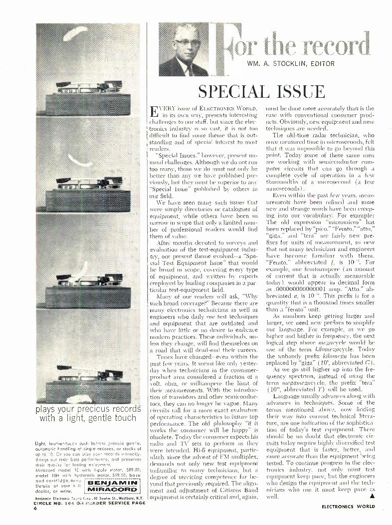
w rt1.'cord WM. A. STOCKLIN, EDITOR
SPECIAL ISSUE EVERY issue of ELECTRONICS WORLD,
in its own way, presents interesting challenges to our staff. but since the elec- tronics industry is so vast, it is not too difficult to find some theme that is out- standing and of special interest to most readers.
"Special Issues," however, present un- usual challenges. Although we do not run too many, those we do must not only be better than any we have published pre- viously, but they must be superior to any "Special Issue" published by others in our field.
We have seen many such issues that were simply directories or catalogues of equipment, while others have been so narrow in scope that only a limited num- ber of professional readers would find them of value.
After months devoted to surveys and evaluation of the test -equipment indus- try, our present theme evolved -a "Spe- cial Test Equipment Issue" that would be broad in scope, covering every type of equipment, and written by experts employed by leading companies in a par- ticular test -equipment field.
Many of our readers will ask, "Why such broad coverage ?" Because there are many electronics technicians as well as engineers who daily use test techniques and equipment that are outdated and who have little or no desire to embrace modern practices. These individuals, un- less they change, will find themselves on a road that will dead -end their careers.
Times have changed -even within the past few years. It seems like only yester- day when technicians in the consumer - product area considered a fraction of a volt, ohm, or milliampere the limit of their measurements. With the introduc- tion of transistors and other semiconduc- tors, they can no longer be vague. Many circuits call for a more exact evaluation of operating characteristics to insure top performance. The old philosophy "if it works the consumer will be happy" is
obsolete. Today the consumer expects his radio and TV sets to perform as they were intended. Hi -fi equipment, partic- ularly since the advent of FM multiplex, demands not only new test equipment unfamiliar to many technicians, but a degree of servicing competence far be- yond that previously required. The align- ment and adjustment of Citizens Band equipment is certainly critical and, again,
must be done more accurately than is the case with conventional consumer prod- ucts. Obviously, new equipment and new techniques are needed.
The old -time radar technician, who once measured time in microseconds, felt that it was impossible to go beyond this point. Today some of these sane men are working with semiconductor com- puter circuits that can go through a complete cycle of operation in a few thousandths of a microsecond ( a few nanoseconds).
Even within the past few years, meas- urements have been refined and some new and strange words have been creep- ing into our vocabulary. For example: The old expression "micromicro" has been replaced by "pico." "Femto," "atto," "giga," and "tern" are fairly new pre- fixes for units of measurement, so new that not many technicians and engineers have become familiar with them. "Femto," abbreviated f, is 10 - ". For example, one femtoampere (an amount of current that is actually measurable today) would appear in decimal form as .000000000000001 amp. "Atto," ab- breviated a, is 10 -'s. This prefix is for a quantity that is a thousand times smaller than a "femto" unit.
As numbers keep getting larger and larger, we need new prefixes to simplify our language. For example, as we go higher and higher in frequency, the next logical step above megacycle would be use of the term kilomegacycle. Today the unhandy prefix kilomega has been replaced by "giga" (10n, abbreviated G) .
As we go still higher up into the fre- quency spectrum, instead of using the term megamegacycle, the prefix "tera" ( 10's, abbreviated T) will be used.
Language usually advances along with advances in techniques. Some of the terms mentioned above, now finding their way into current technical litera- ture, are one indication of the sophistica- tion of today's test equipment. There should be no doubt that electronic cir- cuits today require highly diversified test equipment that is faster, better, and more accurate than the equipment being tested. To continue progress in the elec- tronics industry, not only must test equipment keep pace, but the engineers who design the equipment and the tech- nicians who use it must keep pace as well.
ELECTRONICS WORLD

a
Planning his future is one thing... providing for it is another
. - N: ,
.- .,.;Ë..ì E .,.,,,.a .:. wrrw. . :%s: 414101100.11Pag.
t iawM,rr -aawrwrr *NUN trr,Fs .. r =.+r.r.._- rr s lif:`;i`:M+.
o .::r.wa, it ere wr -11.0'- 0 e
Accredited Member of the National Home Study Council
CREI Founded 1927
Can you do it without more education in electronics? You don't want to accept second -best for yourself and those who depend on you. But you may have to unless you get mo -e education. In electronics, you must learn more to earn more. And, because electronics keeps changing, you must keep learning. Stop -and you soon won't be worth what you're earning now.
Your job and family obligations may keep you from going to school. But you can continue your education in elec- tronics beycnd high school through a CREI Home Study Program in Electronic Engineering Technology.
CREI Programs cover all important areas of electronics including ccmmunications, servomechanisms, even nu- clear engineering technology. They have just one purpose -to get you from where you are now to where you want to be in electronics. They do it by giving you the special- ized knowledge of electronics that will make you worth more money to your employer.
You're eligible if you have a high school education and work in electronics. Our free book gives all the facts. Mail coupon or write: CREI, Dept. 1108 -A, 3224 Sixteenth Street, N. W., Washington 10, D. C.
SEND FOR FREE BOOK N
The Capitol Radio Engineering Institute. Dept. 1108 -A, 3224 Sixteenth St., N. W.
Washington 10 D. C.
Please send me FREE book describing CREI Pro- grams in Electronics and Nuclear Engineering Technology. I am employed in electronics and have a high school education.
ELECTRONIC S
Name Age
Address
City Zone State
Employed by
Type of Prese it Work
Check: Hon Study Residence School C. I. Bin E -1 L

Wondrous stereo sound by Grornrnes .. .
to thrill the budget -minded as well as the affluent. Enjoy the luxury of Grommes E- Line -a happy marriage of thrift and excellence.
Model E -24 24 watt Stereo Anplifier 79.95
Model E -36 36 watt Stereo Amplifier 119.95 (Illustrated above)
Model E -104M FM -AM Stereo Tuner 129.95
Model E -105M FM -AM Stereo Tuner 139.95 (Illustrated below)
Prices include desert -gray metal cover
Write GROMMES Division of Precision Electronics, Inc , 9101 King Street, Franklin Park, Illinois
esn m e-1._
sets the scene...
LETTERS FROM OUR
READERS
TRANSISTOR IGNITION SYSTEMS To the Editors:
Mr. Lynn's question (in the Novem- ber, 1962 "Letters From Our Readers" section) concerning how the transistor- ized ignition system could improve over- all engine performance when energy and secondary voltage considerations seem to favor the standard ignition system is well taken. Since Mr. Saatjian's reply did not do more than prove empirically the superiority of his system ( "Transistor- ized Ignition System," August, 1962), I feel it may be of interest to Mr. Lynn and other readers to discuss why the system performs as it does.
The equation for energy storage in a coil ( ignition coil, in this case ) , shows that as engine speed increases and point closure time decreases, the primary cur- rent and energy stored at break de- crease. The larger the primary induc- tance, the more this current decreases with increasing engine speed. Further- more, since the current in this relation- ship is a function of the second power as opposed to inductance which is a function of the first power, it is clear that it is more important to have a lower inductance and a high current at break than nice versa.
The foregoing being true, you may wonder why not merely increase the primary current by reducing the value of the ballast resistor in the standard ignition system? This is impractical be- cause of the capabilities of the ignition points. For reasonable point life, the largest current that can be interrupted is about 5 or 6 amps and most modern systems push this limit closely. Currents higher than this will cause excessive arc- ing with resultant reduced contact 'life.
It may appear that simply substituting the transistor to carry the primary cur- rent with the points carrying only .6 or .7 amp would be sufficient improvement in the system. This is not true for we would still have the problem of voltage developed across the primary, which is a source of energy loss, not to mention the problem it presents to protect the transistor from destruction.
The problem of high primary induced voltage is licked by the special coil used in the transistorized system. The special coil has greater flux response and closer
8
coupling between primary and second- ary than the usual induction coil, thus allowing more energy transfer from the primary ampere turns to build flux and consequently greater voltage output. Since more energy is transferred to the secondary due to the close coupling, less energy is allowed to return to the pri- mary by the collapsing flux, consequently the primary -induced voltage is less and the problem of protecting the transistor is reduced considerably.
Incidentally, I have built Mr. Saatjian's circuit and have found that it does every- thing he says it will do. My only problem is to find a place to put it in my "Corvair!"
BRI9\ HOGAN Parts & Materials Engineering AC Spark Plug Division General Motors Corporation
1ilwaukee, Wisconsin
REGULATED POWER SUPPLIES To the Editors:
We would like to applaud the excel- lent article "Regulated Transistorized Power Supplies" by John R. Collins in your March issue. The article is a pio- neering step in acquainting your reader- ship with a class of instruments formerly restricted to applications in the heavy military and industrial phases of elec- tronics.
However, we would like to point out that an acknowledgment should have been made to our firm for the use of Fig. 5 on page 41.
SIDNEY NORINSKY, Ad. Mgr. Electronic Measurements Co., Inc. Eatontown, New Jersey
C
WRONG -WAY CHECK To the Editors:
The use of magnetic numbers on checks may speed up banking consider- ably, but I am afraid that the check shown on your April cover won't get routed to the right bank.
If you look carefully, you will see that part of the bank's transit number shown in magnetic ink does not jibe with the transit number printed beside the date on the check.
ROGER MCELROY Los Angeles, Calif.
Reader McElroy has sharp eves. Our
F CIRCLE NO. 131 ON READER SERVICE PAGE
ELECTRONICS WORLD

NOW EVERYONE CAN QUICKLY
Set up and Service Color TV
2
PATTERN DISPLAY STANDARD
Shows correct pattern in window viewer for visual guide
PATTERN SELECTOR
Produces each pattern individually for quick, easy convergence
COLOR SELECTOR
P-oduces each color o.e at a time for accurate color set -up
COLOR GUN KILLER
Aitomatically enables the technician to actuate any combination of the 3 guns
AUTOMATIC DECONVERGENCE
3 Simplifies static and dynamic convergence. No digging into set
DI: MODULATOR ALIGNMENT
Makes alignment extremely simple, without going into the color set
kleto ! ;D5'eo COLOR GENERATOR
Most Complete, Most Versatile, Portable Instrument for Use in the Home and in the Shop Makes Color TV Set -up and Service Easier, Faster than ever!
Now every service technician can be ready to set -up and service color TV with amazing new ease and speed! New advanced design simplifies the entire operation, saves time and work in every installation. Eliminates difficult steps in digging into the color TV set. Gives you new confidence in handling color. Produces Patterns, Burst, and Colors Individually -Provides dot pattern, crosshatch, vertical lines, hori- zontal lines, burst signal, and individual colors -one at a time -on the TV color set -for fastest, easiest check. Unique window- viewer on front of the instrument panel shows you each pattern and color as it should he -gives you an exclusive display standard to use as a sure guide for quick, visual comparison. Provides Accurate, Individual Color Display -Pro- duces Green, Cyan, Blue, H -Y, Q, Magenta, R -Y, Red, I, Yellow, and Burst -one at a time. All colors are crystal - controlled and are produced by a precision delay-line for maximum accuracy. Each color is individually switch - selected-no chance of error.
Provides Accurate NTSC -Type Signal -Color phase angles are maintained in accordance with NTSC specifications. Makes Convergence and Linearity Adjustments Easy -Highly stable crystal- controlled system with
vertical and horizontal sync pulses, assures the ultimate in line and dot stability. Simplifies Demodulator Alignment -The type of color display produced by this instrument provides the ulti- mate in simplicity for precise demodulator alignment. Provides Automatic Deconvergence- Eliminates the necessity for continual static convergence adjustments. The instrument automatically deconverges a white into a color dot trio without digging into the color set to mis- adjust the convergence magnets. It also deconverges a white horizontal or vertical line into red, green and blue parallel lines. This greatly simplifies dynamic convergence adjustments. Provides Exclusive Color Gun Killer- Front -panel switch control makes it easy to disable any combination of the three color guns. Eliminates continuous adjustment of the background or screen controls, or connection of a shorting clip inside the receiver. The switch also selects the individual grids of the color tube and connects to a front -panel jack to simplify demodulator alignment.
Provides Switch -Selected R.F. Signals- Factory- tuned, for channels 3, 4, and 5 -for open channel use in your area.
Model 850 also includes other features that make it invaluable for home and shop use. Net, $19995
See Your B &K Distributor or Write for Catalog AP21 -N
B & K MANUFACTURING CO. Division of DYNASCAN CORPORATION
1801 W. BELLE PLAINE AVE. CHICAGO 13, ILL. Canada: Atlas Radio Corp., 50 Wingold, Toronto 19, Ont. Export: Empire Exporters, 253 Broadway, New York 7, U.S.A.
August, 1963 CIRCLE NO. 103 ON READER SERVICE PAGE 9

; WHAT'S REALLY NEW
IN FREQUENCY STANDARDS?
O ELTEC'S NEW MODEL 600! The First Truly Low Cost Precision Citizens Band
Frequency Standard On The Market!
ONLY
$34995 F.O.B. Middletown
5 times more accurate than FCC requirements
Eltec Model 600
Eltec's Model 600, with amazing accuracy of .00020/0 and frequency range 25 MC to 54 MC, exceeds FCC re- quirements by five times. Now you can quickly adjust frequencies of both transmitter and receiver with real precision. Stability excellent over entire range; easily checked against W.W.V. in the field. Calibration charts furnished - no mathematics or interpolations. Ready to go -- nothing else to buy!
©ELTEC'S NEW ZERo -BEAT! Now A "Combination" "Secondary Frequency Standard"
5 kc F. M. Deviation Standard
And Signal Generator Output
The First Practical Approach To Meeting
and Exceeding Service Needs at 1; 3 The Cost!
TM
ONLY
$69500 F.O.B. Mideletown
ELTEC ZERo -BEAT
ZERo -BEAT exceeds FCC requirements. Features: Range 25 MC to 470 MC; Accuracy - .00003% as secondary standard - .0002% as primary standard; ro interpola- tions; will calibrate new crystals or re- calibrate crystals in portable frequency me -ers; will calibrate deviation meters: dial settings for non -allocated frequencies easily determined in field; simple W.W.V. check in the field; light and portable; operates on 115 V. A.C., 6/12 volt inverter; no temperature correction charts.
ORDER DIRECT OR SEND FOR FREE Rush Model 600 Brochure BROCHURE Rush Zero Beat Brochure Phone -Area Code
203-Di-6-13611
Name
Company
E City 8 Sto'e
C LABORATORIES, INC. 13 Alsop Avenue, Middletown, Conn Eltec Laboratories Inc., 1963
Street
10 CIRCLE NO. 114 ON READER SERVICE PAGE
artist used a blank check from one .source and put his own number in magnetic ink at the bottom of the illustration. The first group of numbers in magnetic ink should actually have been: D210-0012.-Editors.
HIGH -PERFORMANCE IGNITION To the Editors:
In my "High- Performance Transistor Ignition System" de- scribed in your June issue, I have macle one minor change to compensate for a possible difference in the amplification of transistors Q1 and Q2. If such a difference exists, I would suggest that a 5 -ohm, 25 -watt resistor be shunted across the present R7. Also, RL2 is P&B type KA5DY.
M. R. MAY'FIELD Lancaster, Calif.
MUSIC -SPEECH DISCRIMINATOR To the Editors:
Some confusion has arisen regarding the relay used on nay music- speech discriminator (April issue).
The relay is actually marked: Allied Control Co., Inc., T- 154- CC -CC, 1250 oluns, contacts 1 amp. 28 volts d.c. The coil is marked CL686 -1250. This relay is definitely a 1250 - ohm one, and I assume that it was designed for 24 volts d.c., but I do not know this for certain.
I was also under the impression that the relay was a low - cost stock item, but conceivably it Kvas a special unit. The relay may be purchased from Fenico, Inc., Irwin, Pennsyl- vania, under the stock number RL2594.
The relay is used as the collector load of the Schmitt trig- ger. Any change of this value will shift the operating point of the circuit. Any reasonable 24 -volt d.c. relay may be used, but the values of R25, R26, R27, and R28 %gill have to be changed somewhat.
FRANK D. GROSS
Phoenix, Arizona
Also, in answer to many queries, the discriminator is not available in kit form nor is the author's unit available for sale or loan. -Editors.
e
MICROPHONE VOLUME CONTROL To the Editors:
We read with great interest your article in the .April issue of ELECTRONICS WORLD entitled "Microphone Volume Con- trol" by Art Trauffer. One reason for our interest is that Mr. Trauffer's mike volume control is very useful and can be used in many instances. A second reason is that Switchcraft has been manufacturing a similar volume control for many years. Part No. 329. However, since many of your readers might want to assemble such a control themselves, we would like to make a few suggestions.
One, for best results, use this type of volume control in a high -impedance circuit only; two, the female mike connector should be located off -center to facilitate mounting on micro- phones used with stands.
C. J. ScIII-LTZ Switchcraft. inc. Chicago, Ill.
TECHNICAL WRITERS To the Editors:
There was a typographical error in my article ` Are You a
Potential Electronics Technical Writer?" (May, 1963). The salary r.:nge given for trainees and junior writers on page 59 should have been from $65 to approximately $100 per week.
CYRrs GLICKSTEIX Flushing, N. Y.
The article gives exactly the same salary range for trainees and junior writers as for intermediate writers. This. of course. is not correct.- Editors.
ELECTRONICS WORLD

RCA introduces anew easy way
to learn electronics at home
Learn faster, remember more with this revolutionary new "learning method ". And RCA Institutes, Inc. is first to bring it to you!
Forget all your old ideas about learning! The newest nletllod, RCA "Autotext uses the latest scientific devel- opment in the field of home training! RCA " Autotext' is
a system of programmed instruction. accurately planned so that as you read a series of statements, questions. and answers. you learn almost without realizing it! Its fun to learn this new RCA way!
We'll prove it to your RCA Institutes now offers you a com- plete Home Training Course using RCA " Autotext" called "Intro- duction to Electronics." In addition, you get a complete set of experiment lessons, service practice lessons, and all the kits you need. You learn electronics theory faster with less effort.
FREE OFFER! We'll send you complete information on the amazing new RCA "Autotext ", along with a FREE SAMPLE of a
Home Training lesson to prove to you how easy it is to learn this new way. Check ''Autotext ", and infor- mation will be rushed to you.
RCA INSTITUTES, INC., Dept. EW -83
A Service of Radio Corporation of America 350 West 4th St., New York 14, N. Y.
Pacific Electric Bldg., 610 S. Main St., Los Angeles 14, Calif.
eftThe Most Trusted Name
VAT®
August, 1963
in Electronics
WIDE CHOICE OF HOME TRAINING COURSES: In addit on to Introduction to Electronics, RCA Institutes offers this com- plete selection of Home Training Courses:
Electronics Fundamentals* Communications Electronics TV Servicing FCC License Preparation Color TV Mobile Communications Transistors Automation Electronics Electronic Drafting Computer Programming
*Also available in Spanish
All RCA Institutes Home Training Courses are complete step by step easy -to- understand units. You get prime quality equipment in the kits furnished to you to keep and use on the job. In addition, RCA's liberal tuition plan affords you the most economical possible method of home study training. You pay for lessons only as you order them. If you should wish to interrupt your training for any reason, you do not owe one cent. Licensed by the N. Y. State Department of Education. Approved for Veterans.
CLASSROOM TRAINING AVAILABLE IN NEW YORK CITY, LOS
ANGELES, AND CHERRY HILL (NEAR CAMDEN) NEW JERSEY.
For information on Classroom Training see our ad on page 57.
RCA Institutes, Inc. Dept. EW -83 350 West 4th St., New York 14, N. Y. Pacific Electric Bldg., 610 S. MJin St., Los Angeles, Calif. Please rush me FREE illustrated book with information checked below. No obligation. No salesman will call. ' Autotext" Home Training Classroom Training (choice of city) Name Age
Address
City Zone State
CANADIANS: Take advantage of these same RCA Institutes Courses at no additional cost. No postage, no customs, no delay. Fill out this coupon and send in envelope to: RCA Victor Ltd., 5581 Royal Mount Ave., Montreal 9, Quebec. 1
11

a11111A
AMI A : rummems
HI -FI PRODUCT REPORT TESTED BY HIRSCH- HOL'CK I,.4BS
Shure Model 560 Lavalier Microphone Scott 350 -B Stereo Tuner
Shure Model 560 Lavalier Microphone For copy of manufacturer's brochure, circle No. 56 on coupon (page 19).
THE Sluice Model 560 lavalier micro- phone is a dual- impedance dynamic
unit designed for applications requiring a wearable microphone. Typical usage includes teaching, lecturing, or other activities where the speaker wishes to leave his hands free. The 560 is a com- pact, cylindrical microphone, finished in flat black and measuring less than 4" long and 1%" diameter. \Weighing only 5 ounces, it comes with a lavalier cord and clip so the unit can be worn around the neck. It may also be hand -held or mounted on a stand with an accessory swivel adapter.
The microphone, as shipped, is con- nected for high -impedance operation. The load impedance should be at least 100,000 ohms. By changing its internal connections, it may be converted into a
low- impedance microphone operating into a 150- to 250 -ohm load. The unit is supplied with an integral 18 -foot, two - conductor shielded cable.
The manufacturer's specifications rate the Model 560 as having a smooth, uni- form response from 40 to 10,000 cps, with rising characteristics to 4500 cps. It is omnidirectional and has a rated voltage sensitivity of -57 db referred to 1 volt per microbar at 1000 cps, with a ±3 db tolerance. We measured its re- sponse by comparison with cur cali- brated laboratory microphone and found it to be in general agreement with the response curve in the microphone in-
[1] +10 o
struction sheet. At the lower frequen- cies, the measured response was better than the manufacturer's curve, while above 4500 cps it was lower. The re- sponse was ± 4 db from 20 to 2500 cps, rising to about +10 (lb at 3500 cps and falling to -10 db at about 6000 cps. The voltage sensitivity was -55 (lb re- ferred to 1 volt per microbar at middle frequencies.
We used the microphone in a public - address application, and it performed very well. The sound quality was crisp, clean, and highly intelligible. Feedback problems which had existed with some other microphones were greatly reduced or eliminated with this unit. The Model 560 lavalier microphone is priced at 825.00.
-10
20 50 IOO 200 500 IKC. 2KC. FR EQUENCY-CPS
5KC. IOKC.
Scott 350 -B Stereo Tuner For copi/ of manufacturer's brochure, circle No. 57 on coupon (page 19).
THE Scott 350 -B FM stereo tuner is similar to the FM portions of the
Model 333 FM -AM tuner and Model 340 tuner -amplifier, which were de-
12
scribed in previous ENV Lab Tested Re- ports. For those who already have good stereo amplifiers, or do not need an AM tuner, the Model 350 -B offers the same
high quality FM performance as the other units.
The silver -plated, shielded front end uses a low -noise cascode r.f. amplifier and a triode- pentode oscillator 'mixer. The wide -band ratio detector is pre- ceded by two i.f. amplifiers and a limiter stage. The multiplex demodulator uses the switching -type circuits found in other Scott tuners and receivers. Noisy reception of stereo broadcasts can be improved, at the expense of separation, by the switchable sub -channel filter. An- other filter circuit rolls off high -fre- quency response without affecting chan- nel separation. The "Sonic Monitor" cir- cuit provides a positive indication of a stereo broadcast. When a switch is
moved from "Listen" to "Monitor," the (Continued on page 73)
ELECTRONICS WORLD

Ad Well worthy of the Fisher name, both in performance and in ease of construction...Beautifully pack- aged and `instructed'... Excellent specifications, and the performance equals or exceeds the specs?'
-AUDIO MAGAZINE
Exclusive StrataKit construction.
Exclusive d'Arsonval bias and balance meter.
Exclusive third -speaker output with volume control.
/ 41t. '04,..,, =LC ti f :) H ), 1
ier The Fisher KX -200 StrataKit, the 80 -watt stereo control -amplifier kit, $169.5C*
This is the most powerful and in every way the most advanced single- chassis stereo control -amplifier kit you can buy - and by far the easiest you can build.
The 80 -watt music power output (IHFM Standard, both channels) assures peak performance with even the most inefficient speakers. Engineering features never before offered in an integrated control -amplifier kit result in unequaled versatility. And the exclusive Fisher StrataKit method of kit construction makes the techni- cal skill or previous experience of the builder completely unimportant and immaterial.
But the most exclusive thing about the KX -200 is the Fisher name -- your guarantee of a head start in kit building before you even pick up your screwdriver!
r FREE! $1.00 VALUE! The Kit Builder's Manual: a new, illustrated guide to high -fidelity kit construction.
FISHER RADIO CORPORATION 21 -38 44th Drive Long Island City 1, N Y. Please send me without charge The Kit Builder's Manual, complete with detailed information on all Fisher StrataKits.
The Kit Builder's
Manual
Name
Address
City Zone_ State 07811
WALNIII OR MAHOGANY CABINET. 124.95. METAL CABINET. S15.9S. PRICES SLIGHTLY NIGHER IN THE FAR WEST. EXPORT.. EI,..IER FAL
August, 1963 CIRCLE NO. 116 ON READER
1147 ERNATI ONAL. INC.. LONG ISLAND CITY 1. M. Y. ,NAD, TRI.TEL ASSOCIATES. LTD.. WILLOWDALE. ONT.
SERVICE PAGE 13

SERVICE TECHNICIANS, ENGINEERS, TEST LABS SAY . . THE POPULAR MIGHTY MITE IS
Here it THE
Designed for the present anc far into the future. Tests all of your pres- enttubes plus the new F CA Nuvis - ors and N ovars, GE Cornpactrons anc Sylvania 10 yin tubes -.
A complete tube tester that is smaller than a portable type- writer yet outperforms testers costing hundreds of dollars. A real money maker for the serviceman and a trusty com- panion for ergineers, maintenance men and experimenters. Even though the Mighty Mite weighs less than 8 pounds, new circuity by Sencore enables you to use a meter to check grid leakage as high as 100 megohms and gas condi- tions that cause as little as one half microamp of grid cur- rent to flow. Then too, it checks for emission at operating levels and shorts or leakage up to 120,000 ohms between all elements. This analytical "stethoscope" approach rinds troublesome tubes even when large mutual conductance testers fail. And it does all this by merely setting four con- trols labeled A, B, C, & D.
Check these plus Sencore features: New, stick -proof D'Arsonval Meter will not burn out even with a shorted tube Meter glows in dark for easy reading behind TV set.
14
Finds 'em Fast!
Checks 'em Ail!
New large Speedy Set -Up Tube Chart in cover, cuts set -up time Rugged, all -steel carrying case and easy grip handle
Smallest complete tester made, less than one foot square. The Mighty Mite will test every standard radio and TV
tube that you encounter, nearly 2000 in all, including foreign, five star, auto radio tubes (without damage) plus the new GE Compactrons, RCA Nuvistors and Novars and Sylvania 10 pin tubes.
Mighty Mite also has larger, easy -to -read type in the set- up booklet to insur' faster testing. Why don't you join the thousands of servicemen, engineers, and technicians who now own a Mighty Mite tube tester? Tube substitution is becoming impossible and costly with nearly 2000 tubes in use today. Ask your authorized Sencore Distributor for the New Improved Mighty Mite. Size: 101/4" x 91/4" x 31/2".
Wt. 8 lbs. MODEL TC114
Sencore Sam says .
"They all agree . the Mighty Mite is the real answer for the man on the go."
SENCORE
Dealer Net $74.50
ADDISON, ILLINOIS
CIRCLE NO. 136 ON READER SERVICE PAGE ELECTRONICS WORLD

Pick the course for your career...
Electronics Technology
A comprehensive program
covering Automation, Com-
munications, Computers,
Industrial Controls, Tele-
vision, Transistors, and
preparation for a 1st
Class FCC License.
First Class FCC License
If you want a 1st Class
FCC ticket quickly, this
streamlined program will
do the trick and enable
you to maintain and serv-
ice all types of transmit-
ting equipment.
Electronic Communications
Mobile Radio, Microwave
and 2nd Class FCC Prep-
aration are just a few of
the topics covered in this
"compact" program . . .
Carrier Telephony too, if you so desire.
Broadcast Engineering
Here's an excellent stu-
dio engineering program
which will get you a 1st
Class FCC License and
teach you all about Pro-
gram Transmission and
Broadcast Transmitters.
Get A Commercial FCC License ...Or Your Money Back!
A Commercial FCC License is proof of electronics skill and knowledge. Many top jobs require it ... every em- ployer understands its significance. In your possession, an FCC Commercial Ticket stamps you as a man who knows and understands electronics theory . a man who's ready for the high -paid, more challenging positions. Cleveland Institute home study is far and away the quickest, most economical way to prepare for the FCC License examination. And that's why we can make this exclusive statement:
The training programs described above will pre- pare you for the FCC License specified. Should you fail to pass the FCC examination after completing the course, we will refund all tuition payments. You get an FCC License ... or your money back!
Before you turn this page, select the program that fits your career objective. Then, mark your selection on the
Cleveland Institute of Electronics 1776 E. 17th Street, Dept. EW -80 Cleveland 14, Ohio
August, 1963 Accredited Member
coupon below and mail it to us today. We'll send you .. .
without obligation ... complete details on our effective Cleveland Institute home study. Act NOW . and insure your future in electronics.
Mail Coupon TODAY For FREE Catalog
Cleveland Institute o 1776 E. 17th St., Dept. ESC -m) Cleveland 14, Ohio
Please send FREE Career Informa- tion prepared to help me get ahead in Electronics, without further obligation.
CHECK AREA OF MOST INTEREST-
Electronics Technology Industrial Electronics Broadcast Engineering
f Electronics
How to Succeed in Electronics
First Class FCC License Electronic Communications
other
Your present occupation
Name Age_ (please print)
Address
City Zone State IL, Approved for Veteran's Training under Korean GI Bill. ENV-80 J
15

the challenging field of ommunications LICENSE REQUIREMENTS
TTING P
CAIVADIAN LIEN SQL EQ(/ /p cT USA /DENT /FY /l'Jv SIGNALSN
S SWL CB ATES cß /N ci
FREQUENCIES & TIME ZONE
TABLES
SE
NAMNE
SVJIT ÑAM Voul° T CB TO
RADIO C tSTS
DER -4NS BUSINESS RADIO
LICENSE QUALIFICATIENT
SERVICE REQUIRED
EQUIP
1963 COMMUNICATIONS HANDI300
148 pages of comprehensive information
4 big sections covering each of the main branches of communication
illustrative graphs, charts and tables
The 1963 COMMUNICATIONS HANDBOOK is now on sale at your favorite newsstand or electronics parts stores. Or get your copy by
111-
using this handy coupon. Just PRINT your name and address clearly and enclose $1.00, the cost of the HANDBOOK, plus 15¢ to cover mailing and handling charges
I(Canada and foreign countries -
$1.25 plus 25¢ postage).
r
COMMUNICATIONS 1963 HANDBOOK
AL_ NEW! A F.ctFilled
Guice on Hoe Ena ,one Can Use Ind Eaioy
Zack, Cum,aU,l,atna
C :Izens sen. _e ((B)
,od.Wa.e uzay
Radio Amateur (Hams)
Business Band Radiotelephone
EW83
Ziff -Davis Publishing Dept. CH3 One Park Avenue New York 16, New York
Company
NAME
ADDRESS
CITY ZONE STATE
(please print)
CIRCLE NO. 100 ON READER SERVICE PAGE -*
READER SERVICE PAGE
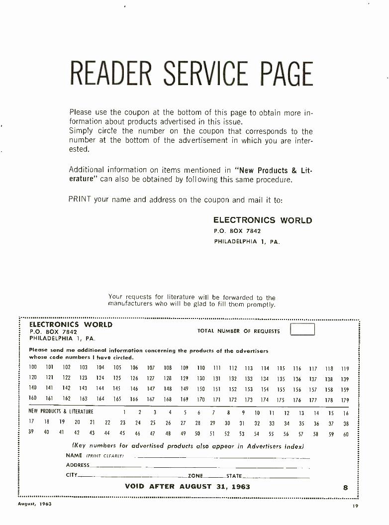
Please use the coupon at the bottom of this page to obtain more in- formation about products advertised in this issue. Simply circle the number on the coupon that corresponds to the number at the bottom of the advertisement in which you are inter- ested.
Additional information on items mentioned in "New Products & Lit- erature" can also be obtained by foll owing this same procedure.
PRINT your name and address on the coupon and mail it to:
ELECTRONICS WORLD P.O. BOX 7842
PHILADELPHIA 1, PA.
Your requests for literature will be forwarded to the manufacturers who will be glad to fill them promptly.
ELECTRONICS WORLD P.O. BOX 7842 PHILADELPHIA 1, PA.
TOTAL NUMBER OF REQUESTS
Please send me additional information concerning the products of the advertisers whose code numbers I have circled.
100 101 102 103 104 105 106 107 108 109 110 111 112 113 114 115 116 117 118 119
120 121 122 123 124 125 126 127 128 129 130 131 132 133 134 135 136 137 138 139
140 141 142 143 144 145 146 147 148 149 150 151 152 153 154 155 156 157 158 159
160 161 162 163 164 165 166 167 168 169 170 171 172 173 174 175 176 177 178 179
NEW PRODUCTS g LITERATURE 1 2 3 4 5 6 7 8 9 10 11 12 13 14 15 16
17 18 19 20 21 22 23 24 25 26 27 28 29 30 31 32 33 34 35 36 37 38
39 40 41 42 43 44 45 46 47 48 49 50 51 52 53 54 55 56 57 58 59 60
(Key numbers for advertised products also appear in Advertisers Index) NAME (PRINT CLEARLY)
ADDRESS
CITY ZONE STATE
VOID AFTER AUGUST 31, 1963 8
August, 1963 19

3 SPEAKERS CAN NOW REPLACE 16
These three new Delco Radio 8 -10 -ohm replacement speakers permit you to cut 16 numbers from your inventory. They can replace all units in current Gen- eral Motors cars and many competitive makes They
Delco install easily and quickly, take a "tip jack," "blade," or solder connection. Excellent for home hi -fi and TV sets, too! Speak up For the latest in replacement speakers. Call your United Delco supplier today.
THREE NEW SPEAKERS, ALL WITH SLOTTED MOUNTING HOLES SPECIAL Number Size Magnet Wt. Mounting UNIVERSAL 8 -10 -OHM
6126 6x9" 1.5 oz. front/ rear 6 x 9" REAR SPEAKER PACKAGE Contains all materials necessary for
6127 4x10' 1.6 oz. front /rear rear -seat speaker installation: Speaker,
6128 6' round 2.5 oz. rear -seat G ill, Wirirg, Switch. Part No. 6122.
20
Delco Radio Automotive Radio Service Parts and Electro- Mechanical Devices are distributed nationa'ly through United Delco DELCO RADIO, Division of General Motors, Kokomo, Indiana
Un ited Delco CIRCLE NO. 110 ON READER SERVICE PAGE ELECTRONICS WORLD

PHOTOFACT
GIVES YOU MAXIMUM
TV COVERAGE to keep you up -to- the -minute! NOW - PHOTOFACT gives you quicker- than -ever service data coverage for TV and for more of the kind of equipment you most frequently repair!
It's the same famous PHOTOFACT time -saving, troubleshooting help -everything you need to earn more daily. You get: Exclusive Standard Notation Schematics, packed with all the service details you need; full photo coverage of all chassis views; com- plete replacement parts lists; tube placement dia- grams; actual waveform photos; CircuiTrace`° for printed boards: alternate tuner data; terminal iden- tification and connections: disassembly instructions; field servicing notes -plus dozens of other great time -saving features.
Take the right step to fast, profit -building servic- ing -see your Sams Distributor for details on a money- saving PHOTOFACT Standing Order Subscrip- tion and Easy -Buy Library -or send coupon today!
SAVE
3O PER SET!
RCA Victor 213G235RV
A TYPICAL
MONTH'S TV
COVERAGE (June 1963)
Sylvania 19709 Olympic 9T22
Truetone 2DC3360
Westinghouse H- K3911U
Coronado TV2 -9650A
Panasonic AN -14 Coronado TV2-9442A Olympic 9TV19 -B
Emerson C-200 lA
Capehart 19PT25 J. C. Penney 19P362A
SIGN UP TODAY FOR A MONEY- SAVING PHOTOFACT STANDING ORDER SUBSCRIPTION!
With a Standing Order Subscription to receive PHOTOFACT regularly each month as issued, you pay only $1.95 per Set instead of the regular $2.25 price. You save 30¢ per Set -and you keep right up with the rapidly- increasing current model output! You enjoy the same 3O¢ per Set savings when you purchase an Easy -Buy PHOTOFACT Library. Take advantage of substantial savings -sign up for a Standing Order Subscription or Easy -Buy Library with your Sams Distributor, or send coupon now for full details.
SAVE WITH A STANDING ORDER SUBSCRIPTION!
Electrohome Cameo
Clairtone ST-801
HOWARD W. SAMS & CO., INC. Howard W. Sams & Co., Inc., Dept. 5 -H3 4300 W. 62nd St., Indianapolis 6, Indiana
Enter my Photofact Standing Order Subscription Send full information on money- saving Easy -Buy Plan
My Distributor is:
Shop Name
Attn.
Address
City L Zone State
August, 1963 CIRCLE NO. 132 ON READER SERVICE PAGE 21

UNCOMPROMISING ENGINEERING CREATES THE BEST BUY... EICO
NEW ADVANCED GENERAL PURPOSE 5" CSCILLOSCCPE #427
Kit 66E.95 Wfrec $109.95 Vertical amplifier with 3 push -gull stages, direct coupled throughout; 4- posi-io., rrequency -com- pensated V inputattenuator irtesnal calibrating voltage. Recurrent sweeps ran 10cps -100kc in 4 overlapping rangés; cho ce of in +, - 6ocps, or ext. syrc; fully aitomat c sync. opera- tion; full retrace blanking. Intnsity, focus and astigmatism controls on panel. Sharp, clean, non -blooming tram. Instantane_us drift -free po- sitioning. Conven ont direct pate connections. V amp: 10mv p-pdcm sens. ;flat cc- 500kc, -6db at lmc; 1 meg nput Z. I- amp 0.5V p -p /cm sens.; 2cps -450kc flat response 19 meg input Z.
AC VTVM & AMPLIFIER #250 Kit $49.55 Wired 1.79.95
Highly sensitive, rt liable AC VTVM & wideban amplifier. Measure; 100 microvolt: to 300V I 12 ranges; 10c -600kc ±Odb response, 10 me ohms input impedance, ±3;, accuracy, Wid band amplifier switch -controlled for external use: Ec -800kc response, 5VRMS output, 5K ohms out- put impedance, gain control, noise -40db. Frame -grid triode cathode folbwar nput circuit, freq.- compensated nput attenuaior, cathode cir- cuit attenuator. Regulated power supply. AC VTVM #255 Kit $44.95 Wired $72.95 All the precise VTVM facilities o: the #250 less external use of the wide -band amps fier.
CV
AC VOLT -WATT METER #2E1` Kit $49.95 Wired $79.95
AC voltmeter & load- compensated audio watt meter of unique quality. Measures AC voltage from imv to 1000V in 11 ranges, power from .015mw to 150W in 7 ranges, across standard loads from 4 to 600 ohms. Tapped power resistor load (4, 8, 16 and 600 ohms) handles up to 80W or 8 ohms and 40W on other taps: Switch to external load up to 150W. Meter automatically compensated for any load selected, internal or external, to provide single watt scale.
Listen to the EICO Hour. WABC -FM, N. Y. 95.5 MC, Mon. -Fri., 7:15 -B P.M. Export Dept., Return Agencies Inc., 431 Greenwich St., New York 18
VACUUM TUBE VOLTMETER #222 Complete with exciiusive dual- purpose Uni -Probe®
('J. S. Pat.' Kit $2795 W', red $42.95
Entirely electronic, direct Leading measurement of resistance, and AC & DC to 1500V in 5 ranges. May be calibrated without remove. from cabinet. Complete electronic overload protection, plus fuse. 1% precision ceramic resistors. Exclusive AC /DC Uni -Probe® selects DC or AC -Ohms. DC voltmeter input impedance 11 megohms, accu- racy ±3 %. AC voltmeter input impedance 1
megohm, accuracy ±-5%. Ohmmeter 0.2 ohms to 1000 megohms In 5 ranges.
IN- CIRCUIT CAPACITOR FESTER #95 Kit $19.95 Wired $39.95
Tests capacitors in the circuit without unsolder - - ing. Checks for shorts, (evert in the presence of as little as I ohm shunt resistance). Checks open units (as little as SMMF In the circuit). Measures capacitance with ±10% accuracy between 0.1mf and 50mí. Measures RC product, convertible into dissipation or power factor. Utilizes electron -ray tube EM84 /6FG6 w (h sharp bar pattern. Line adjust control permits maximum sermitivity r gardless of line voltage variations.
TRANSISTOR & CIRCUIT TESTER #680 Kit $25.95 Tired $39.95
_- Meassres (CEO, ICBC & 0Cß directly, ACß In- directly, without charts or special settings - plus all dc volts, currents & resistances needed to service transistor equipment Battery powered. SOpA, 31/2" face meter movement provides sensi- tivity & scale length necessary for accuracy. Built -in 20,000ßV VON( facilities free your other test equipment.
6 & 12 VOLT BATTERY ELIMINATOR & CHARGER #1064
Kit $43.95 Wised $52.95 Heavy -duty 2- ranges for operating any mobile radio & transceiver including transistor or "hy- brid" types. Also usable as charger for either 6 or 12 volt batteries. Varhaole transformer pro- vides continuous output adjustment. 2 meters simultaneously observe output voltage and cur- rent. Ratings: 0.8V: 10A continuous, 20A inter- mittent; 0 -16V: 6A cont., 10A interm. AC ripple: 0 -16V range: C.3% @ 2A, 1% @ 6A. Heavy -duty selenum rectifiers, & automatic reset overload relay.
METERED VARIABLE AUTO -TRANSFORMER AC BENCH SUPPLIES
10T3e 3A rating Kit $35.95 hired $47.85 1078: 71/2A rating Kit 642.95 Wired $54.95 r study of components under varyirg line condf-
ons. Delivers any voltage up to 140VAC with inear variation of output throughout entire
nge. Smooth rotary brush -tap controlled by enel iiai.Highly efficent variable toroidal core sign Auto -transformer. No waveform distortion
r voltage drop from no -load to full load. Sepa- te output ammeter & output voltmeter.
TUBE TESTER ADAPTOR #610 Kit $5.95 Wired $11.95
Adapts EICO models 625 or 666 tube testers for testing the following new tube types: nuvistor 5 pin; uvistor 7 pin; novar 10 pin miniature; ompaclron; 12 pin. Included are roll -chart sup - Iements for both 625 and 666 models.
'WA; EICO ELECTRONIC INSTRUMENT CO., INC.
3300 NO. BLVD., L.I.C. 1, N. Y.
EICO, 3100 N. Blvd., L.I.C. 1, N.Y.
Send free 32 -page catalog & Distributor's name.
Send Free Schematic of Model No
Send new 36 -page GUIDEBOOK TO HI-Fl 3 for which I enclose 25c for postage & handling.
Name
9 Address
City Zone .... State
EW-8
Over I MILLION EICO Instruments In use. Most EICO Dealers offer budgrt terms.
22 CIRCLE NO. 111 ON R.7ADER SERVICE PAGE ELECTRONICS WORLD

8 o
By FREDERICK VAN VEEN /General Radio Company
Significant developments in the past ten years, especially those that haue advanced the art of measuring. New types of test instruments that measure frequency by counting, record quantities graphically, measure L, C, R, Z, voltage, and special microwave measuring devices.
'
;,/
THERE has been, over the past decade, a tremendous improvement in electronic measuring instruments. The rapid advances in precision, accuracy, and con-
venience of measurement have played a vital part in the electronics "boom" that has meant a 600% rise in sales dollars. Everything, in a sense, begins with measurements, and the limits of measurement are the limits of science.
The boom in electronic measuring instruments is a mixed blessing to the average technician. Ten years ago it was pretty easy to select a bridge or voltmeter for a specific job. Shop- ping was a matter of looking at a few catalogues and inter - comparing some specifications. Then the measurement in- dustry really expanded, manufacturers outdid one another in offering varieties of multipurpose instruments, and the catalogues bulged. The 1953 IRE Directory listed 69 manu- facturers of bridges; the 1963 edition lists 140. Under "Graphic Recorders" the 1953 directory lists 47 companies, the current volume, 145. The 1963 edition lists no fewer than 224 companies making digital counters, a category not even included in the directory of a decade ago!
The hundreds of different instruments manufactured to measure frequency, impedance, resistance, inductance, ca-
pacitance, voltage, and current represent a \vide choice of accuracies, features, and price. There is also, of course, the duplication inherent in our competitive system. No one article or series of articles can do justice to the overwhelming number of direct- reading instruments available today. The emphasis here will be on the more significant developments of the past ten years, and especially those that have advanced the state of the measurement art.
Mechanical and Convenience Improvements The measuring instruments of 20 or 30 years ago were
typically big, black, square, and heavy. This was simply the way people thought instruments should look; indestructible, reliable, conservative. But styles change and most of the black, square instruments went the way of black, square automobiles. Today's instruments enjoy the benefits of new materials, miniaturization, and much of what is sometimes called "human engineering" but which has always been a part of just good mechanical design.
Instrument cabinets now try to be all things to all people; some can be quickly adapted to relay -rack, bench, or portable use. Then there is the tiltable cabinet, with a captive cover that serves as an easel -type stand when the instrument is in use. Extensible front legs on mangy cabinets let the user look
Probably the most important new type of in- strument of the past decade is the frequency meter using digital counting techniques. This example, the General Radio 1151 -A, is a gen- eral- purpose counter for laboratory or produc- tion -line use that can measure frequency accurately from a fraction of a cps up to 300 kc. The unit also measures the period of a cycle and frequency ratios. Price: $1195.
August, 1963 23

A
C
(B)
(A) Many direct- reading instruments are highly versatile since they may combine several functions within a sin- gle unit. Our example is in the audio field. The device shown, the Eico 902, combines an a.c. v.t.v.m. for ac- curate audio measurements, and generators and filter circuits for making both harmonic- distortion and inter - modulation- distortion tests. Such measurements are read directly on the meter face. Distortion figures are within 5% of full scale and the voltage figures are ±4% of the full -scale reading. The price is $250, factory- wired.
With the increasing use of semiconductor diodes in equipment have come specialized testers for checking these components. Many of these testers have been designed for practical laboratory use as well as for incoming diode stock inspection. One typical unit, the Seco 210, includes tests for zener diodes, silicon and germanium power and signal diodes, as well as selenium rectifiers. Various variable sources of power are incorporated in the circuit. Results are displayed on two meters. Price of unit: $154.95.
(C) Not all frequency meters are digital devices. Typical of the more com- mon and, incidentally, less expensive type is the Lampkin 105 -B shown. This instrument is a heterodyne -type frequency meter with a built -in crystal calibrator. It is used to measure transmitter frequencies anywhere in the range of 100 kc. to 175 mc. In addition, it will function as an accurate weak -signal generator for receiver alignment. Instrument meets FCC require- ments for a frequency monitor in the mobile -radio service below 50 mc. With some additional equipment, the meter will also meet the FCC accuracy requirements for the newer split -channel frequencies. The price is $260.
at the front panel head -on whether he is sitting or standing at the bench. And cabinets of the larger manufacturers come in standard sizes, so that they can be stacked into a neat arrangement.
Readouts have improved tremendously. The meters are larger with scales designed for easy reading. And, too, there are now digits -neon digits, incandescent digits, projected digits, digits in windows, and more digits on printed tape.
Instruments are lower -the form factor apparently follows that of automobiles. The day of the three -inch -high instru- ment has arrived, apparently to save relay -rack space. In- struments used in the field have become more portable than ever, as they are transistorized. Also, some instruments with heavy power demands are starting to "go portable," thanks to the rechargeable nickel- cadmium battery.
There are so many convenience improvements in instru- ments that it is difficult to list them all. But one that deserves special note is the quality of instruction manuals. Another is
the greater availability of manufacturers' sales and service engineers. Manuals and consulting services can be just as important as some of the instrument's technical specs.
Instrument Specifications
The buyer of an electronic instrument must be guided by the specifications published by the manufacturer, but the catalogue shopper who tries to select an instrument purely by published data had better be on his toes.
Not that the manufacturers aren't truthful. Dishonest specifications are fortunately a rarity in this business, because they punish their perpetrators too quickly. But every manu- facturer wants to put his best foot forward and stress the specifications where he is strongest. Also, there are many honest differences of opinion among manufacturers on just how best to state something. Take, for instance, the problem of specifying the low limit of measurement on a v.t.v.m. Suppose the voltmeter has a low range with a full scale of 10 microvolts, and an accuracy of ± 10% of full scale. The voltmeter will certainly measure voltages below 10 micro- volts, but a 1- microvolt reading might be wrong by 100 %,
and most people would not consider that a measurement. Another aspect of the same problem: a 3% voltmeter is gen- erally more accurate than a 2% voltmeter if the 3% is 3% of in-
dicated value and the 2% is 2% of full scale. The moral of all this is that you should not play the numbers game with in- strument specifications, but should read words as well.
One of the best ways to approach laboratory instrument selection is to consult the manufacturer. Sales engineers who sell such electronic instruments are, by and large, extremely competent, helpful, and low- pressure. They will try to steer you to the right choice of instrument, even if it means steer- ing you to another company. They offer a valuable consulting service for anyone with a measurement problem, and the wise shopper takes advantage of it.
But even knowing where to start is a problem. There is a bewilderingly large number of electronic measuring instru- ments made by several hundred different manufacturers to measure more than 200 different electrical and electronic parameters, separately and in combination, in many different frequency ranges, and to varying degrees of accuracy and precision. You may know exactly what you want to measure and the conditions of measurement, yet there is no quick way to narrow your selection to those instruments that qualify. Certain so- called "buyers' guides" try to classify instruments, but the task is too much for them. Several manufacturers publish excellent catalogues that bring order to their own houses. But the job of classifying all instruments in terms of well- defined standards remains.
A hopeful beginning is the recently publishedr program of IEEE Subcommittee 25.1 on Basic Standards and Calibra- tion Methods. As a first step, this committee has designated three echelons of accuracy level. Echelon I is the highest calibration accuracy available within a country, Echelon II an intermediate level, typically that of the calibration labora- tory of an instrument manufacturer, and Echelon III a level at which measuring instruments are calibrated before use by the ultimate consumer. For each echelon, various IEEE Technical Committees will report on the measurement ac- curacies available and needed. In its statement of objectives, the IEEE Committee says, "An appraisal of the present status of electrical measurements points up mainly the limited availability of complete, reliable technical information." All who make, buy, or use electronic instruments will wish this particular committee Godspeed in its work.
Measurement of Frequency Today's most popular frequency -measuring instrument -
the counter -scarcely existed ten years ago. Now that digital counting techniques are being widely applied to so many measurements, the frequency counter must be considered the most important new instrument of the past decade. The
24 ELECTRONICS WORLD

modern frequency counter represents a unique melding of borrowed technologies: the flip -flop circuit from atomic re- search, pulse techniques from radar, binary switching logic from computers. The counter became a practical instrument with the development of a method of converting binary in- formation to decimal, new digital indicators, and improved switching devices.
The principles of counters are well known, and are here worth only passing mention: Successive cycles of the fre- quency to be measured are passed through a "gate" and counted, the total being indicated by a digital display. The counting time, or the time that the gate is open, is determined by a reference crystal oscillator, usually built into the counter. If the gate is set to remain open for one second, the digit display is direct- reading in cycles per second. The unit of time is established by a crystal oscillator -usually called the "time base" -and the accuracy of this time base determines, more than any other single factor, the accuracy of frequency measurement.
If one is interested chiefly in accuracy, then the significant specification is the accuracy and stability of the time -base oscillator. The possible error corresponding to time -base inaccuracy must be added to the plus -or -minus one -count error inherent in all counters. Other errors can be caused by noise -, but these are harder to evaluate.
Frequency ranges of counters vary widely, but the upper limit for direct -reading counters is presently about 50 mc. Heterodyne converters extend this range up to 1000 mc. with no sacrifice in accuracy, and transfer techniques are used from 1000 Inc. to above 10,000 mc.
One of the most valuable features a counter can offer is versatility -the ability to rearrange its components for differ- ent types of measurements. Thus many firms advertise "uni- versal" counters. This usually means that the instrument can measure not only frequency, but also period, time interval, and frequency ratio as well.
To pleasure period, the functions of the "unknown" and time -base signals are interchanged, so that successive cycles of the unknown frequency open and close the gate, while "clock" pulses from the time base are counted. As a result, the digits displayed indicate the number of time units (e.g., 10 -µsec. units if the time base is a 100 -kc. oscillator) passed during one cycle of the unknown frequency. At frequencies much lower than that of the time base, a period measurement
will yield greater precision, due to the higher count used. A time -interval measurement also counts "clock" pulses
from the time base, but here the gate is opened by one signal and closed by another. In frequency -ratio measurement, one signal is used to open and close the gate, while the other is counted.
A consideration of increasing importance is the adaptability of the counter to accessory instruments. If you require per- manent records of measurements, you will need either a data printer or the combination of digital -to- analog converter and analog recorder. Whether a particular counter will operate with a certain printer or D/A converter depends on the type of coding used, input and output voltage levels, and other considerations. Failure to check these in advance can easily lead to a pair of incompatible instruments.
Digital counters are by no means the only way to measure frequency, and it is unlikely that they will ever take over completely. For some applications, in fact, digits are a real nuisance. Suppose, for example, that you are trying to adjust a variable- frequency oscillator to exactly 12,230 kc., while monitoring the output frequency on a counter. You trim one way and then the other, as the digits dance tantalizingly around (but not on) the desired frequency. How you would long, at this point, for a heterodyne instrument with which your ears could guide you quickly to zero beat! It is a good idea to remember that any good variable -frequency reference, such as a signal generator, can be used with mixer and de- tector to measure frequency.
At frequencies up to about 1.5 mc., there are lab analog instruments available. One, using an interpolation technique with most of the frequency suppressed onto a switch setting, offers an over -all accuracy of ± 0.2% from 3 cps to 1.5 mc. And instruments for coarse frequency measurements -wave- meters and grid -dip meters -still enjoy a brisk market.
There is every reason to expect further substantial im- provements in frequency measurements. Accuracy is, as men- tioned, largely a function of the accuracy or stability of the frequency reference. Thus, it is possible to increase the accuracy of any counter by the use of a highly accurate fre- quency standard as the time base.
Measurement of Capacitance & Inductance Capacitance and inductance measurements involve similar
techniques and limitations. The basic instrument for precision
(A) Graphic recorders are widely used in industry where a written chart showing one or more variable functions is required. The recorder shown, a Moseley 2D -4, draws rectangular coordinate curves from two related sources of d.c. electrical information on standard graph paper. Writing area is 10 x 15 inches. High -gain solid -state servo amplifiers drive the two motors that are coupled to balance pots and recording pen. Ten calibrated input ranges from 0.5 mv. /div. to 10 v. /div. may be selected from the front panel of the recorder. The liquid -ink pen has a maximum writing speed of 15 inches per second. Price is $1490.
IB) Even vacuum -tube voltmeters have become transistorized. DeVry transistorized meter combines advantages of a v.t.v.m. with those of a sensitive microammeter for service -bench use. Instrument is completely
portable, operating on four flashlight batteries. It has usual a.c., d.c., and resistance ranges, along with four d.c. current ranges from 50 ¡ta. to 50 ma. full -scale. D.c. input impedance is 10 meg on most ranges. The price of the voltmeter is $89.50 ready -wired or $64.50 in kit form.
(Cl Graphic recorders need not be large and bulky as shown by the Amprobe ATM -2. This is actually two most -frequently used recorders in a single compact carrying case. One of the units is an expanded - range a.c. voltmeter and the other is a high -current a.c. ammeter. Roll of 21/2" wide pressure -sensitive paper, traveling at 12" per hour car- ries the record of voltage and current. With the paper removed, pointer position is visible on a calibrated scale so that unit can be used as an indicating meter. Price of the 2- recorder unit and case is $181.20.
August, 1963 25

measurements is the bridge -an instrument that permits the adjustment of a calibrated known until a state of electrical balance exists between it and the unknown. Here, as in fre- quency measurements, the major burden is on the accuracy of the "calibrated known," or standard. But even the best standard is of little practical use in measurements unless its accuracy can be somehow extended over a wide range of values. One significant advance in bridges over the past few years is the transformer ratio -arm bridge, a device for ex- tending the usefulness of a single standard over a range from 1 /1000 to 1000 times its value or better, with no sacrifice in accuracy. Although the transformer bridge was originally conceived over 30 years ago, its principles have only recently been exploited in commercial instruments. The most accurate capacitance bridges available use ratio arms to achieve direct - reading accuracy of 0.01% over a wide range of capacitance.
Capacitance standards can be made more accurate than inductance standards. The capacitance bridges just men- tioned use ± 0.005% standard capacitors, for example, where- as the best standard inductors are ± 0.1% units. Inductance bridges therefore use capacitors, rather than inductors, as standard reactances. The most accurate inductance bridges available offer ± 0.1% direct -reading accuracy.
The ultimate accuracy of most precision bridges is, inci- dentally, well beyond the direct- reading accuracy. A high degree of resolution, that is, a readout of five, six, or more significant figures, can be used for ultraprecise intercompari- sons. One of the 0.1% capacitance bridges, for example, per- mits intercomparison of capacitors to within one part per million.
Capacitors and inductors can be measured in terms of either series or parallel equivalent circuits, and many bridges therefore offer switch selection of C,, Cn, Ls, and Lr. The difference between Ls and L and between C. and Cr is less than 1% for inductors with "Vs" over 10 and for capacitors whose dissipation factor is less than 0.1.
Resistance Measurements
The instruments most often used to measure resistance are the ohmmeters included with many voltmeters. The accuracy of such an ohmmeter is limited to 5 or 10 %, partly because of trying to squeeze an infinite range into a finite scale.
The resistance bridge is easily able to achieve 0.1% ac-
curacy up to 10 megohms or so. Measurements of very high resistance are made by megohm bridges, which supply the required high voltages. One megohm bridge will measure resistances up to 10'' ohms, with 1% accuracy up to 10''.
Resistance limit bridges are direct -reading in percent devi- ation rather than in ohms. Such bridges are used by produc- tion -line personnel to determine quickly whether a component is within specified tolerance.
The exceptional accuracy of frequency standards has been applied to the measurement and standardization of other quantities. The ohm has thus been defined in terms of fre- quency and length, and standard resistors can now be speci- fied in terms of a few parts per million. Standard resistors are used in series and parallel combinations, linear voltage di- viders, and conventional bridges to extend their usefulness over a wide -range of measurement. Present state -of- the -art for general- purpose, wide -range resistance bridges seems to be the same as for capacitance: ±0.01 %.
The most popular bridges are those that measure resist- ance, capacitance, and inductance -the so- called "universal" bridges. This popularity is easy to understand when, in this day of four - and five -figure prices, less than $500 can buy a self -contained, battery -operated, portable, five- bridges -in- one instrument that measures C, R, and L to ± 1 %, and also measures dissipation factor and "Q."
Voltage Measurement The digital revolution came to voltmeters less than ten
years ago, and digital voltmeters are now produced by many manufacturers. The extra precision afforded by digital read- out is of especial advantage in d.c. measurements, where the attainable accuracy warrants such fine resolution. Digital voltmeters are considerably more expensive than the usual analog meters of comparable ranges and quality, and this relation is likely to continue. Another relation that seems basic is that between the accuracies attainable in a.c. and d.c. measurements. While d.c. voltage can be measured to about ±0.002 %, the best a.c. measurements are at least an order of magnitude less accurate. The a.c. voltage is usually measured in terms of a d.c. equivalent, and the translation from one to the other has to cost accuracy.
The scales on almost all a.c. voltmeters are calibrated in terms of r.m.s. voltage. However, until a year or two ago,
(A) Another example of an electronic counter is the Hewlett- Packard 52141.. This instrument totalizes and measures frequency and period. In addition, it can directly display readings in practical units, such as gallons /sec. or ft. /min. from appropriate transducers. Two sets of dec- ades are used: one to register the signal being counted; the other may be preset to any number from 1 to 100,000 to control a gate circuit that may be used to operate other equipment. Unit can be used to monitor automated processes, and for production testing and for lab- oratory applications. The price of the electronic counter is $1475.
(B) There is still much equipment in use that employs vacuum tubes. To
check the performance of these tubes on the service bench requires an easy -to -use, flexible tube tester, such as the Triplett 3414 shown. This unit checks for shorts, leakage, and plate conductance. A self -contained
roll chart supplies test setup data. Sockets are provided for octal, loctal, and miniature tube types. The price of the tester is $109.50.
26
(C) An example of direct -reading, accurate capacitance bridge that can measure very small capacitance values is the Boonton Electronics 75B shown. The instrument was originally designed for use in measuring the temperature coefficient of small "zero temperature coefficient" ceramic capacitors. It is also used for capacitance measurements of semiconductors at millivolt levels. Lowest range of the bridge is the extremely small value of only 0.1 pf. full -scale. Values as high as 1000 pf. can be measured with this particular capacitance bridge. Price: $1375.
ELECTRONICS WORLD

most voltmeters actually responded to either peak or average value, with the scale conversion in terms of r.m.s. voltage assuming sine -wave input. Now `true- r.m.s." voltmeters have begun to appear in quantity. The most common type of true - r.m.s. voltmeter measures a.c. voltage in terms of its heating effect on a thermocoupl. This effect is compared with the heating effect produced by a reference voltage. Other true - r.m.s. meters use dynamometers and rectifiers whose non - linearities synthesize r.m.s. response. True- r.m.s. response cannot be maintained by these means for all input waveforms, and the specification "maximum crest factor," that is, the maximum ratio of peak to r.m.s. voltage for which the volt- meter is reliable, is especially significant in pulse work.
The peak- and average- responding voltmeters are highly refined from years of development, and will probably con- tinue to enjoy considerable popularity based on their price advantage.
Most peak instruments rectify the input voltage and then amplify the d.c. Their chief advantage is good high -frequency response. Also, since they include a d.c. amplifier, they can be made to measure both a.c. and d.c. voltage quite easily. A disadvantage at low voltages is that the a.c. output no longer bears a linear relation to the a.c. input.
The typical average -responding voltmeter first amplifies the input signal, then rectifies it. A wide -band amplifier, stabilized by negative feedback, is generally used. Although its high -frequency limit is well below that of the peak -re- sponding voltmeter, it can measure much smaller voltages.
At very high frequencies, broadband amplifiers are diffi- cult to design. At low voltage levels, rectifiers assume com- plicated characteristics. Therefore, the measurement of high - frequency, low -level voltages poses a special problem. One method of solving it is to accept the complex rectifier be- havior and compensate for it on the meter scale. Another is to use a matched pair of semiconductor rectifiers, one to rectify the input voltage, the other to rectify a low- frequency reference voltage, and to compare the d.c. outputs. Commer- cial instruments of both types are available.
The measurement of very small d.c. voltages is best ac- complished by an electrometer. Some electrometers convert the small d.c. voltage to an a.c. voltage that is amplified and metered, while others use direct -coupled amplifiers. A good electrometer can measure d.c. voltages down to a few micro- volts or less and currents to below 100 femtoamperes ( a femtoampere is equivalent to 10-'5 ampere) .
Wave Analyzers & Graphic Recorders Many voltmeters travel under other names, because they
are only indirectly concerned with mere measurement of voltage. An example is the frequency- selective voltmeter known as a wave analyzer. Operating ahead of the voltmeter in a wave analyzer is a filter that passes only a certain fre- quency band. The bandwidth is a constant number of cycles in some analyzers, a constant percentage of center frequency in others. The constant -cps bandwidth is generally more useful except at very low frequencies or where a logarithmic plot is required. Optimum bandwidth depends on how much detail you need. Very narrow bandwidths give more data but require more time for analysis. Wider bandwidths offer greater convenience at the cost of some detail. A wave ana- lyzer with switch selection of two or three bandwidths lets you have your cake and eat it, too.
Of course, the chief application for wave analyzers is wave- form measurement, and thus the oscilloscope and graphic recorder are important accessories.
The combination of a wave analyzer and an oscilloscope or recorder is known as a spectrum analyzer. Spectrum an- alyzers are available from very low frequencies to at least 100,000 mc. Most use automatic frequency sweeping to give continuous oscilloscope display. The modern spectrum analyzer combines the features (Continued on page 72) August, 1963
ON OUR COVER
A
B
D
F
THE group of electronic test instruments on our cover this month indicates, in a small way, the tremendous variety of
equipment being used in laboratories and on service benches. For example, the portable audio oscillator at (A), the Hewlett -
Packard 204B, is designed for reliable audio work in the labora- tory or field. It is fully transistorized and battery- operated with a balanced, isolated 600 -ohm output. The frequency range of 5 cps to 560 kc. means that the oscillator can be used for gen- erating signals outside of the audio range as well. Price: $315.
The field of automatic testing is represented by the Lavoie "Robotester" LA -303, shown at (B). This is an automatic, tape - programmed measuring instrument that can select any 2 of 250 circuit points and then automatically measure resistance, d.c. or a.c. voltage, insulation resistance, and impedance. Between 60 and 100 tests per minute indicate wiring or assembly failures by flashing -light indicators. Price of the basic unit is $5600.
Representing the TV- servicing field is the Sencore CA122 color - circuit analyzer (C). This instrument generates all the test pat- terns (color bars, dots, cross -hatch) and signals for checling and adjusting the circuits in a color -TV receiver from antenna to tri -color picture tube. There are 10 crystal -controlled gated color bars of the RCA type. Signals are available in both r.f. and i.t. ranges; there are also video, sync, and audio signals for checking these portions of the TV set. Price: $187.50.
One of the most useful and versatile pieces of test equipment is the cathode -ray oscilloscope, represented on our cover by the Fairchild -DuMont 766H (D). This is a bench and portable lab scope with a bandwidth from d.c. to 25 mc. The unit uses silicon tran- sistors and features a new high- brightness CRT. The high sensi- tivity of 5 mv. /cm. is provided with a rise time of 15 nsec. Price is $545 without the plug -in preamps and time -base generator.
A universal, general -purpose impedance bridge, the General Radio 1650 -A, is shown at (E). This is a self- contained, battery - operated, portable instrument for the measurement of: induc- tance and "Q" of inductors; capacitance and dissipation factor of capacitors; and a.c. and d.c. resistance of resistors. The unit is actually five bridges in one, together with a transistorized 1 -kc. oscillator and sensitive detector. This bridge has an accuracy of ±1% and is priced at $475.
Graphic recorders are widely used in industry when a written record is required of one or more variables. The instrument (F) is the Brush Mark II recorder. Two channels of analog plus two of coded event or time data may be directly written on the mov- ing roll of chart paper. Four chart speeds are available and, at the slowest speed, over 25 hours of data can be recorded on a 300 -foot chart roll. Available for either ink or electric writing, the recorder is priced at $1495.
Where high- speed, accurate voltage measurements are re- quired, especially by non -skilled personnel, and where this meas- urement is to be available in digital form, the digital voltmeter is used. The Dynascan 111 shown at (G) is an example of a sim- ple, fairly inexpensive instrument of this type. This unit uses all solid -state circuitry except for a single nuvistor. There are four ranges: 1, 10, 100, and 1000 volts d.c. with either polarity at an input impedance of 11 meg on all ranges except for 1 meg on the lowest range. Accuracy is ±0.1 %. Price: $399.50.
27
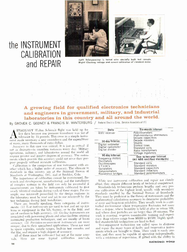
the INSTRUMENT
CALIBRATION
and REPAIR ILeft) Teletypewriter is tested with specially built test console. (Right) Checking voltage and current calibration of standard meter.
A growing field for qualified electronics technicians and engineers in government, military, and industrial laboratories in this country and all around the world.
By GROVER C. GEDNEY & FRANCIS M. WINTERBURG / Federal Electric Corp., Service Associate of ITT
STRONAUT Walter Schirra's flight was held up for five days because one pressure transducer was out of
tolerance by 1 pounds. This error in a simple instru- ment made necessary a new countdown and the expenditure of many, many thousands of extra dollars.
Accuracy in this case was critical. It is just as critical -if not as dramatic -in countless instances every day. Military operations, industry, and laboratories around the world all
require greater and greater degrees of accuracy. The instru- ments which provide this accuracy could not serve their pur- pose properly without accurate calibration.
Calibration is the comparison of one instrument with an-
other which has a higher order of accuracy. The ultimate in
standards in this country are at the National Bureau of
Standards at Washington, D.C. and at Boulder, Colo. The importance of calibration cannot be overstressed. Re-
search and development, manufacturing, and the installation of complex systems in the field can only be successful if
measurements are taken by instruments calibrated to give
nearly identical readings during each of these stages. For ex-
ample, one microvolt prescribed by the design engineer in
the laboratory must be read and set to one microvolt by the test technician during field installation.
There are, broadly speaking, three categories of instru- ments: (1) Test instruments are used to test and set up sys-
tems or equipment in the lab, factory, or in the field., and are of medium to high accuracy. (2) On -line instruments are
associated with processing plants and other facilities utilizing automated production techniques, and are usually of lower accuracy. (3) Precision -measurement instruments are more unique, due to their specialized applications. These are used in space capsules, missile ranges, built -in test consoles and
the like, and require a high degree of accuracy. All of these must be calibrated but not at the same inter-
vals. Here are some typical calibration intervals.
28
Daily WWV receiver
Six -month Interval
30 -day Interval Digital voltmeter Digital radiometer Digital divider
90 -day Interval Frequency meters Oscillators Oscilloscopes V.T.V.M.'s Generators Galvanometers Resistance bridges
Potentiometers High- resistance ohmmeters Decade capacitors Decade resistors Shunts Slotted lines Standard cells Ratio transformers Voltage regulators
One- to two -year Interval (All NBS certified standards)
Standard cells Standard resistors Standard capacitors Standard inductors Standard potentiometers
While test instrument calibration and repair are closely
allied, they require different levels of technical competence. Standards -lab technicians perform lengthy and very pre-
cise calibration of the highest level, usually with secondary standards certified by the National Bureau of Standards. They must be proficient in the theory of instruments and the mathematical calculations necessary to determine probability of error and long -term reliability. They usually work in a con-
trolled environment where temperature fluctuates not more than a degree, where humidity is held at plus or minus 10 %,
and where dust particles are no larger than 10 microns. The work is exacting, requires considerable training and experi- ence. Base salaries range from $6000 to $9500. Highly quali- fied standards -lab technicians are hard to find.
Test -equipment technicians are called upon to diagnose and repair the many types of faulty and inoperative instru- ments which are brought to them. Their work is rarely rou- tine, and they must be capable of operating independently, with a minimum of supervision. If gifted with the ability to
ELECTRONICS WORLD

train others quickly, a test -equipment technician may soon be given the opportunity of assuming supervisory responsi- bilities. He must respect the mission of the standards lab and establish a confidence in the accuracies to which standard instruments are calibrated for his use.
This category of technician, too, is in relatively short sup- ply and the pay scales are only slightly lower than for the standards -lab group -approximately $5000 to $8000 a year.
As in other branches of electronics, the opportunities for graduate engineers in this particular field of electronics are growing steadily. The demand for specialized training in this area has been great enough for George Washington Uni- versity to establish a "Center for Measurement Science" which offers an engineering curriculum oriented to the meas- urement field. Called "metrologists," these engineers develop new measurement criteria and prepare measurement and cal- ibration procedures which the technician may perform. They may be called upon to assist technicians in solving difficult instrument troubleshooting problems, or to determine the probable error of calibration in several instrument systems tied together. Salaries range from $6000 to $15,000 and more.
Background Requirements Most of the instrumentation we are concerned with at
Federal Electric Corporation is in the electrical- electronic field. To qualify for employment in one of our calibration and repair facilities, a man must be a high- school graduate; he must have had one or two years of electronic schooling in a trade service school or engineering college; and three years of experience, at least one of which was in the test instrument field.
Math is extremely important; the more the better. We look for people who have had college physics, college algebra, trigonometry, analytical geometry, statistics, and even cal- culus. Any math above the high- school level conditions a man's mind to think along technical lines.
With this background, we can train technicians for cali- bration work on the job. Let's take, for example, a position in our DEW Line Communications and Electronic Equip- ment Depot.
The man usually begins by working with a more experi- enced man on the repair and overhaul of meters, or in trouble- shooting a piece of test equipment. He then begins to assist in the calibration of test equipment. We have a set of written procedures to follow that becomes routine with experience. After a month or two of this, he may be ready to become a member of the mobile calibration team. This is a group of five technicians who carry certified instruments from our headquarters in Paramus. N.J. to different areas of the DEW Line Early Warning System in the Arctic, where they cali- brate the test equipment that keeps the giant communica- tions and radar system operating at peak efficiency.
After months of mobile team experience, a technician may be qualified to begin Nvork in the Standards Laboratory. He
will assist the more experienced men, learn the procedures, and become proficient in the techniques of transfer calibra- tion from NBS standards to our secondary standards.
In choosing a calibration technician for the Early Warning System, a man who is single and willing to travel is preferred to a married man. We do have married men working on the mobile teams and will hire them if well qualified, but the single man is given preference because of having fewer home responsibilities.
These mobile teams travel to Alaska, across Canada at the Arctic Circle, and into Greenland and may be gone for four months at a time. They return to the Communications and Electronic Equipment Depot for three or four weeks to re- calibrate their standard instruments and then again return to the DEW Line.
There is adequate opportunity for the married man with a family in the fixed laboratories or facilities. Only on mobile teams staying away from a home base for a considerable period of time is the unmarried man preferred.
Opportunities for Technicians The instrument calibration and repair field is growing and
the supply of qualified men is completely inadequate. For example, there are only about 14,000 engineers and techni- cians who are members of the Instrument Society of America. The U.S. Air Force, to cite another example, has within the past five years: (1) installed a standards laboratory at Newark, Ohio; (2) built 19 area laboratories; and (3) added 149 pre- cision measurement laboratories.
Within industry, the example of the International Tele- phone and Telegraph Corporation might be of interest. To assure the accuracy and reliability of its products, ITT Fed- eral Laboratories established in 1956 one of the first large - scale standards laboratories to serve an industrial facility. For several years, the calibration and repair of test instru- ments have been important services of Federal Electric Corporation.
The instrument technician of today is not confined to the laboratory or factory. If he is well qualified, he enjoys an unprecedented demand for his services.
ABOUT THE COMPANY The Federal Electric Corp. operates instrumentation calibration centers
in this country and overseas. At Paramus, N.J. there is the Communications and Electronic Equipment Depot established by the Air Force to repair and calibrate our Early Warning System instrumentation. There are 40 people employed there, including three traveling calibration teams made up of five technicians each. Some 20 are employed at an instrumentation center in Albuquerque, N.M. to serve Sandia Corporation, prime contractor for the Atomic Energy Commission, and other users in the Southwest.
The company also operates a standards laboratory at Chateauroux, France, serving the Air Force in Europe, Near and Middle East, and Africa. This group, consisting of 125 people, has technical teams and mobile calibration trailers for on-site checking and repair of electronic equipment. Over 400 are employed by the company in our Pacific Missile Range. These are re- sponsible for the operation and maintenance of the Navy's range instrumen- tation facilities at Point Arguello and the missile launch facilities in California. Over 1.500 pieces of precision measuring equipment are cali- brated and repaired by this facility, which has its own 15 -man .standards laboratory.
(Left) Technician is shown calibrating a u.h.f. signal generator. (Center) Calibration of a vacuum -tube volt- meter against a standard. (Right) Checking an oscilloscope time base against a master frequency standard.
August, 1963 29

NAVAL OBSERVATORY TIME SIGNALS
By H. CHARLES WOOD
Description, use, and schedules for the "time ticks"
that are broadcast on low,
medium, and high frequencies.
Editor's Note: Although not as widely known and used as the
National Bureau of Standards WWV and WWVH time signals,
useful time signals are also broadcast by a number of Navy radio stations to ships around the world. This article discusses these
time signals, tells how to interpret them, and gives the broadcast schedules of the stations involved.
JOHN HARRISON of Yorkshire, England is credited with developing the first practical shipboard clock (or chro- nometer) in 1735, and thus earned a handsome reward
of £ 40,000 from the British Parliament. Prior to that date, accurate navigation on the high seas could not be achieved, because one of the major factors of celestial navigation is an
accurate knowledge of time; an impossible feat in the days of the Ancient Mariner. This accounted for a seaman's reluc- tance to venture beyond the sight of land.
It wasn't long after Harrison's invention was made avail- able to sea captains that new - problems arose, the most im-
portant of which was the inability to predict the daily rate of error of the chronometers when the vessels were away from their home ports for a long period of time. This error is normally applied to the watch -time to determine the correct local time.
A small step forward was made in the 19th century when most of the major ports of the world were equipped with a
"time ball" which was dropped from a conspicuous location in the harbor at noon. The sea captains in port would then set their chronometers accordingly. Unfortunately, however, not all port officials had the correct time. The problem of
incorrect time, and the consequent error in a ship's position, continued throughout the 19th century, resulting in much loss of life and property, and was not solved until the in- vention of radio at the beginning of the 20th century.
Stations & Schedules
In 1904, U.S. Navy Radio Station NSS, newly established at Washington, D.C., began broadcasting time signals syn- chronized with the precision clocks at the Naval Observatory. This was the first significant advancement since Harrison perfected his invention nearly two centuries before, for now at last mariners all over the world could correct their chro- nometers with a signal of known accuracy.
Throughout the years, the U.S. system of radio time signals has been improved in accuracy and presentation, the power of the transmitters has been increased, new frequencies have been added, and new Naval radio stations have been built. Today, there is scarcely a spot on the planet that is not within range of at least one of the daily time signals.
Naval Observatory time signals are now being broadcast at
30
numerous times throughout the day by five widely separated Navy radio stations: NSS Washington, D.C,; NBA Canal Zone; NPG San Francisco, California; NPM Honolulu; and NPN Guam. The hours of the transmissions and the fre- quencies of emission are listed in Table 1. At the top of each tabulation are the call letters, location of the station, and the frequency of transmission in kilocycles. The Greenwich Mean Time (GMT) of transmission is located in the left -hand column, followed by a conversion to the zone times main- tained throughout the United States. Local time for any other location can be computed by applying the time zone number to the GMT. For example, Los Angeles, California is located in time zone +8. This means that 8 hours must be subtracted from GMT to obtain the local time of Los Angeles. Thus the 2400 hours midnight time signal will be heard in California at 1600 hours local time (4:00 p.m. for you landlubbers). It will be one hour later if your community is on daylight saving time. World time zone charts are available at U.S. Hydrographie Offices, nautical equipment stores, and most bookshops.
Now let's examine the time signal itself, as it is graphically displayed in Fig. 1. Essentially, (Continued on page 82)
STATION: NSS Washington, D. C.
Frequency in kc.: 121.95; 5810; 9425; 13,515; 17,0504; 23,650
Pacific Std. Alaska- Honolulu Time Zone +8 Time Zone +10 GMT=
Eastern Std. Time Zone +5
- Central Std. Time Zone; +6
Mount. Std. Time Zone. +7
0155-0200 2055 -2100 1955 -2000 1855 -1900
0555-0600 0055 - 0100 2355 - 2400 2255 - 2300
0755-0800 0255 -0300 0155 -0200 0055 -0100
1155-1200 0655 -0700 0555 - 0600 ,0455 -0500
1355-1400 0855 -0900 0755 -0800 0655 -0700
1755-1800 1255 -1300 1155 -1200 1055.1100
1955-2000 1455 -1500 1355.1400 1255 -1300
2355-2400 1855 -1900 1755 -1800 1655 - 1700
STATION: NBA Balboa, Canal Zone Frequency in kc.. 147.85; 5448.5; 11,080; 17,697.5
1755 -1800 1555 -1600 2155 - 2200 1955 - 2000 2355 -2400 - 2155 -2200 0355 -0400 0155 -0200 0555 -0600 0355 -0400 0955 -1000 0755 -0800 1155 -1200 0955 -1000 1555 - 1600 1355 - 1400
GMT= Eastern Std.
Time Zone +5 Central Std.
Time Zone +8 Mount. Std.
Time Zone +7
0455 -0500 2355 -2400 2255 -2300 2155 -2200
0955.1000 0455 -0500 0355 -0400 0255.0300
1655 -1700 1155 -1200 1055 -1100 0955 -1000
2355 -2400 1855 -1900 1755 -1800 1655 -1700
Pacific Std. Alaska - Honolulu Time hoe +8 Time Zone +10
2055 -2100 1855 -1900 0155 -0200 2355 -2400 0855 -0900 0655 -0700 1555 -1600 1355 -1400
STATION: NPG San Francisco, California Frequency in kc.: 114.95; 4010; 6428.5; 9277.5; 12,966; 17,055.2; 22,635 '
STATION: NPM Honolulu Frequency in kc.: 131.05; 4525; 9050; 13,655; 17,122.4; 22,593
STATION: NPN Guam Frequency in kc.: 484; 4955; 81150; 13,530; 17,530; 21,760
GMT. Eastern Std.
Time Zone +5 Central Std.
Time Zone +6 Mount. Std.
Time Zone +7 0555- 0600 1155-1200 1755-1800 2355 - 2400
0055 -0100 0655.0700 1255 -1300 1855 1900
2355 0555 1155 1755
-2400 - 0600 -1200 -1800
2255 0455 1055 1655
-2300 -0500 -1100 -1700
Pacific Std- Alaska- Heaolulo Time Zone +6 Time Zone +10
2155 -2200 1955 -2000 0355 -0400 0155 -0200 0955 -1000 0755.0800 1555 -1600 1355 -1400
Table 1. Schedule of the U.S. Naval Observatory time signals.
Fig. 1. Arrangement of "time ticks" as transmitted by stations.
It.S. NAVAL OISSElil'A'ri, Ill' 'TIME SI -AI.S
10 Sec
55th Min. Be,i;minU of Time Signal
20 Sec 30 Sec
L111111111111111111 11111111
29th Sec Blank
40 Sec 50 Sec GO See
' 1 56th Min TIME 1
56th thru 59th I
S;st Sec Sec Blank Blank /
I
IIIIIIIIIIIIIIIIIIII "11 -1
J1111111111!`1111i11;llll 11 1111.11111
111111111 111111111
29th Sec
Blank
11111111
111111111 111111111
57th Min 'LIME SIGNAL
56th thru 59th I
52nd Sec See Blank I
Blank 1
¡WWII I 111--.1 55th Mtn TIME SIGN
56th thru 59th I
53rd Sec Sec Blank 1
E1aul . / I / iIIIIIIII II IIII 111111 II -I
I 1 59th Min TIME SIGNAL
56th Ihre 59th 1
54th Sec I Sec Slack i
Blank , I
29th Sec
(II'11111111iII1111Ì1111H
I1IIIIIIWIIIIIIIIIIII I-I koch Hin TIME SIGNAI.
51st thru 59th I
Sec Sec Blank
illlllllll1!"1!llll
ELECTRONICS WORLD

SIGNAL-GENERATING
EQUIPMENT
L
Devices used to generate test signals from below the audio range up through microwaves. Performance, specifications, and effect of semiconductors on equipment design are covered. By HOWARD L. ROBERTS / Hewlett- Packard Co.
SCNAL-geiieiatiig equipment comprises a wide variety of electronic instruments for generating test signals. This class of instruments includes everything from the
human finger, placed on a grid connection, to complicated check -out equipment which automatically generates a num- ber of frequencies, voltages, and other signals for quickly testing intricate missile systems.
The finger test may be all that you need if you merely want an indication of whether the equipment is working or not. But when you need to know how well the equipment works, then the appropriate piece of signal- generating equip- ment must be called upon to provide the answer.
If, for instance, you want to measure distortion in an audio amplifier, you need an oscillator that generates sine waves with far less distortion than you expect the amplifier to have. If you want to measure the rise time of a switching circuit, you ought to have a pulse generator that produces pulses with rise times faster than the switching circuit.
Types of Equipment Signal -generating devices may be loosely grouped into two
categories: special -purpose and general -purpose generators. Special- purpose generators are designed for specific kinds of tests and usually generate only those combinations of frequen- cies needed to test certain kinds of equipment. An example of this type is an FM stereo test generator. Special -purpose gen- erators are best suited for making repetitive measurements since their built -in features make specific tests faster.
General- purpose equipment may not have many combina- tions of signals but usually can generate signals over broader ranges of frequency and amplitude. These generators find most use in the experimental and development laboratory, both professional and hobbyist, but are often used for specific tests as well. Presumably, any test performed by a special - purpose generator can be performed by an assortment of
When an accurate, stable v.h.f. signal source is required for receiver or v.h.f. amplifier measurements, then a standard sig- nal generator is required. Our example is the Hewlett -Pack- ard 608D. The instrument is especially suited for precise tests of narrow -band v.h.f. aircraft communications equipment. It has a calibrated output of 0.1 ¡iv. to 0.5 v. throughout the 10 to 420 -mc. band. Output frequency can be set to with- in a few kc. with built -in crystal calibrator. Price: $1300.
August, 1963 31
general- purpose equipment, but several instruments may be required to do the same job.
Since the basic design principles involved in general -pur- pose laboratory instruments are also used in special- purpose generators, we'll confine this discussion to general- purpose instruments.
Signal- generating equipment is often grouped according to the shape of the output signal waveform. Sine -wave gener- ators form one important category since the sine wave is the most fundamental waveform. These instruments are widely used to test equipment performance at discrete frequencies.
Oscillators and Signal Generators Among sine -wave generating equipment, a distinction is
made between oscillators and signal generators. A signal gen- erator is an oscillator that has accurately known amounts of output power as well as known frequencies. In many cases, this means simply that a signal generator has a meter to show the power generated by the output stage, and a precision at- tenuator for cutting down the indicated power by known amounts.
At audio frequencies it is a simple enough matter to read oscillator output with a lab voltmeter. For this reason, output meters are not included in the majority of audio oscillators. At r.f. frequencies, though, voltage measurements are more corn-

plex so that r.f. generators include a built -in output meter designed especially for each generator. (An r.f. generator without a meter is known as a "signal source.")
RC oscillators have dominated the audio and neighboring ranges for more than twenty years. This range extends from subsonic through ultrasonic and into the low- frequency r.f. ranges.
RC oscillators are so named because their frequency- deter- mining networks consist only of resistance and capacitance -no inductance whatever. The reason for using an RC circuit is that if an LC circuit were used, the large inductors required for low- frequency oscillations would be much too cumber- some. The RC oscillator is much lighter, easier to build, and, as it turns out, a good source of distortion -free sine waves.
These oscillators generally use some form of amplitude limiting other than driving a tube to cut -off and /or saturation. The most common form of amplitude control is the use of a
small incandescent lamp as a non -linear resistance in one of the feedback loops. The lamp's resistance changes, if the oscillation amplitude changes, readjusting the amount of feedback to counteract the change in amplitude. This type of limiting prevents the tubes ( or transistors) from being driven beyond their linear operating regions and accounts for the low distortion output of these oscillators.
The oscillator circuit may also be followed by a tuned amplifier -filter ganged to the tuning dial so as to track the oscillator tuning. Filtering attenuates what little harmonic content there may be in the oscillator signal, resulting in
hyper -pure sine -wave output. This type of instrument is
most useful for making distortion measurements on other types of equipment.
Multivibrators with very long time constants are used in instruments for the very low frequencies, some of these op- erating as low as 0.001 cps ( about 1 cycle per 15 minutes!) .
Multivibrators generate square waves, of course, but the square waves are changed to sine waves by wave- shaping networks. This is just opposite to the audio -range sine /square wave generators which start with sine waves and form these into square waves with clipping or triggering circuits.
Above 1 mc., the usual RC oscillator runs into certain prob- lems. The tuning capacitors are in a range of values com- parable to distributed circuit capacitance which makes tun- ing less precise. Phase -shift oscillators, a different form of the RC oscillator, swamp out the stray capacitances and can be used up to 10 mc. and beyond.
Beat -frequency oscillators are also used throughout the low - frequency region. These instruments use two r.f. oscillators, one generating a fixed frequency and the other being tunable.
The outputs of these oscillators are mixed and the difference frequency is separated from the mixture by filter circuits.
The advantage of the beat -frequency oscillator is that very wide frequency ranges can be covered by a single sweep of the tuning dial, at the expense of tuning resolution how- ever. The disadvantage is that the oscillators must be made many times more stable than the desired stability of the out- put signal because of the large step -down in frequency. High - quality beat -frequency oscillators made for laboratory appli- cations do achieve the desired stability, however.
R.F. Signal Generators The designation "r.f." is another all- embracing term, orig-
inally referring to signals that were destined to be radiated or detected as radio waves. As it turns out, radio signals are now propagated at frequencies even lower than 20 kc. ( stand- ard frequency broadcasts such as WWVL) and at super - high frequencies measured in thousands of megacycles ( giga- cycles ) . Our discussion here will be confined mainly to those radio -frequency generators which have lumped LC circuits, using coils and capacitors in the resonant circuit.
During the forty -odd years that these generators have been used, they have undergone considerable refinement. Factors which upset frequency stability have been designed out of the circuits. Manufacturers have learned how to wind coils tightly of low expansion wire on matched ceramic forms so
that there is little change of inductance with a change in
temperature. In high- quality generators, capacitors are made from rigid precision -machined plates, which are silver- or gold -plated for minimum resistance to r.f. surface currents (skin effect). In recent years negative feedback has been used in various ways to improve amplitude stability and modulation characteristics.
Even with all these refinements, a good r.f. signal gen- erator still includes an accurate crystal -controlled frequency calibrator to enable precise setting of frequency. The cali- brator frequency is usually a whole number, such as 1 mc., so that it is easy to spot the harmonics.
Such r.f. generators also include amplitude or frequency modulation capabilities. This enables the generator to supply signals which resemble the actual signals to be used by the equipment being tested.
When the response of a sharp cut -off filter or i.f. circuit is being measured, modulation may wobble the r.f. frequency across the circuit's cut -off point, broadening the apparent response curve. For this reason, most r.f. generators use the master oscillator -power amplifier (MOPA) configuration which isolates the oscillator from the output amplifier, per-
Designed mainly for servicing AM, FM, and TV receivers is the
Hickok 288AX sweep and marker generator. The instrument has
8 bands of unmodulated or AM signal output from 35 kc. to 110
mc. as well as frequency -modulated output up to 160 mc. A
built -in audio oscillator, tunable from 20 to 15,000 cps, is
used for modulation or for audio tests. A crystal calibrator, with a choice of 100- or 1000 -kc. signals, is also provided along with a 3 -range decibel meter. Price of this unit: $315.
32
An example of a versatile pulse generator is the Fairchild - DuMont 404 -B. This device can generate pulses suitable for use in signal -sampling techniques in conjunction with oscil- loscopes. Another application is to trigger scope sweeps at the proper time to view the leading edges of very short tran- sients. Pulses can be generated with widths continuously var- iable from 0.05 to 105 psec., with various delays, and with repetition rates up to 250,000 p.p.s. Generator price: $760.
ELECTRONICS WORLD

A multiplex stereo generator developed for design and produc- tion testing of FM multiplex adapters, tuners, and receivers is the Scott 830. The unit has also been used by FM broadcast stations to produce a composite stereo signal. When feeding a composite stereo signal into the front end of a tuner, the generator's output is used to modulate a laboratory- quality standard FM signal generator. The price of the unit: $600.
Intended mainly for the service technician working on FM multiplex equipment is the Fisher Model 300 multiplex sig- nal generator. The instrument is also suitable for use in production testing. Incorporated are an audio oscillator and an r.f. generator, which is factory tuned to the approx- imate center of the standard FM broadcast band. An output - level indicator is also provided. Price of generator: $495.
mating amplitude modulation of the amplifier without affect- ing the frequency of the oscillator.
The output impedance of r.f. generators deserves special comment. If the output cable and load impedances aren't the same, r.f. energy reflects from the load, giving rise to standing waves. If the generator itself is not matched to the output cable, then reflections are re- reflected, which alters the character of the standing wave and interferes with measurement accuracy. Most r.f. generators are matched to one of the 50, 75, or 300 -ohm impedance levels commonly used but pads or baluns are required to match other imped- ances.
Because of standing waves, the r.f. voltage at the generator may be different from the load voltage. For this reason, an output voltmeter is a reliable indicator of signal strength only when the load is matched to the generator.
The attenuators of r.f. generators require careful design to account for distributed capacitance and inductance. These devices are frequency -sensitive unless components are posi- tioned carefully. Furthermore, the impedance of the atten- uator must be matched to the output cable at all settings.
U.H.F. and Higher Frequencies Above .300 mc. the inductance and capacitance of tuned
circuits become so small that it is difficult to treat them as discrete circuit elements. At these higher frequencies, reso- nant cavities Of one sort or another are generally used as the resonating elements.
Gridded tubes for u.h.f. frequencies have rather odd shapes so that all elements make contact at the right place when installed in a cavity. Above 1000 mc., klystrons are most often used as oscillators.
Microwave signal generators use a single power oscilla- tor for the r.f. channel, avoiding the cost and complexity of a power output stage. Because of this, modulation is usually restricted to pulses and square waves. Modulating waveforms turn the power oscillator completely off and on, making the transition between off and on states as fast as possible to minimize frequency pulling or FM as the klystron voltage changes. On the other hand, it is relatively easy to frequency - modulate a klystron over a range of a few megacycles by applying a saw -tooth voltage to the klystron repeller.
The attenuators of these generators also avoid the use of lumped circuit elements, the waveguide- beyond -cut -off type being favored. This attenuator uses a pickup loop which slides in and out of a length of waveguide that opens into the resonant cavity. The waveguide dimensions are smaller than those required to carry an electromagnetic wave at the frequency of the oscillator but the cavity's magnetic field
August, 1963
leaks into the waveguide. The further the loop is from the cavity end, the weaker the field is and, what is more, the field strength drops off in a predictable manner so that these attenuators are inherently accurate.
Sweep Generators Sweep generators are indispensable for anyone concerned
with circuit response throughout a band of frequencies. A straightforward way of obtaining a sweep frequency is to add a motor drive to the oscillator tuning dial. This approach is widely used at audio and low frequencies, where electronic techniques for changing frequency fail to achieve the neces- sary wide (in terms of number of octaves) bandwidth. The beat -frequency oscillator shines here as a means of getting wide sweeps.
Motor drives are also used at radio frequencies but vi- brating capacitors often serve to vary the oscillator frequency. At microwave frequencies, the voltage -tuned backward -wave oscillator (b.w.o.) can easily sweep through an octave band of frequencies simply by modulating the helix voltage.
Motor- driven sweeps, unless carefully designed, cause mechanical vibrations which induce microphonics that gener- ate spurious oscillations. Motor -driven sweeps are also lim- ited in speed. Electronic sweeps, which vary the oscillator tank circuit's resonant frequency either with a reactance tube, a voltage- variable capacitor, or a saturable reactor, are used wherever possible.
Many service -shop sweep generators have a fixed sweep rate of 60 cps, taken right from the power line. This simpli- fies circuitry and also makes synchronization of related os- cilloscopes easier.
Circuit response is usually displayed on an oscilloscope. The sweep rate should be fast enough to obtain a flickerless display. Slow sweep rates are required for pen recorders which may trace with more detail than a scope does.
Pulse and Square -Wave Generators Pulse and square -wave generators produce signals of an
"off -on" nature by switching between two d.c. levels. These generators are used to check systems which operate in a pulsed mode, such as radar modulators, oscilloscope trig- gering circuits, computer circuits, and teletypewriter systems. These generators are also used for transient response testing of linear systems.
The shape of the input pulse or square wave has to be neatly rectangular if anything is to be learned from the shape of the output pulse. Rounding of the pulse corners, or overshoot, wiggles, and sag of the pulse top, are the symp- toms of system performance so should not be present on the
33
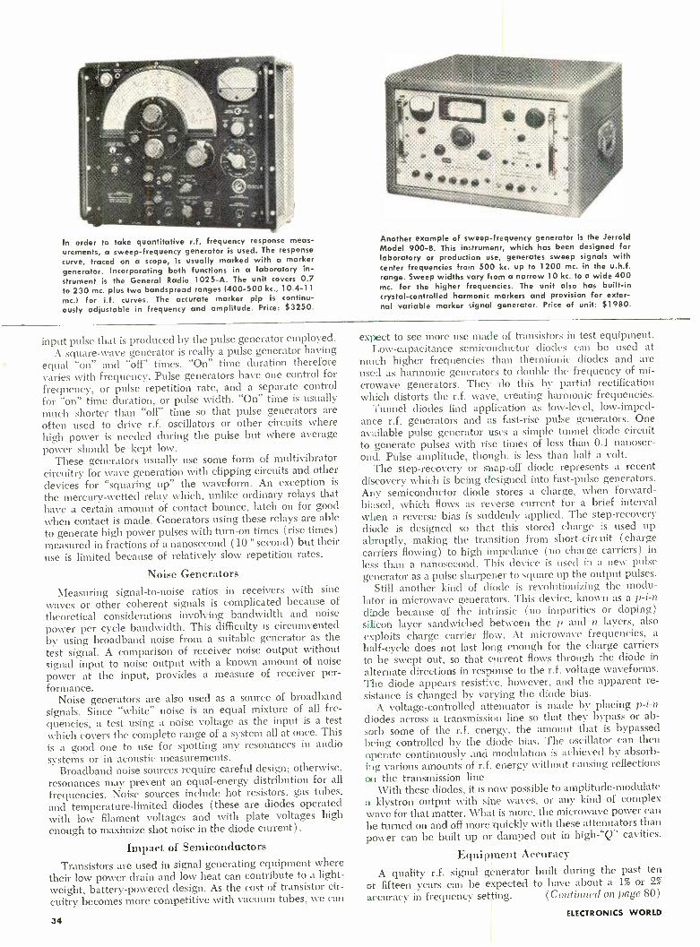
In order to take quantitative r.f. frequency response meas-
urements, a sweep- frequency generator is used. The response
curve, traced on a scope, is usually marked with a marker generator. Incorporating both functions in a laboratory in- strument is the General Radio 1025 -A. The unit covers 0.7 to 230 mc. plus two bandspread ranges (400 -500 kc., 10.4 -11
mc.) for i.f. curves. The accurate marker pip is continu- ously adjustable in frequency and amplitude. Price: $3250.
Another example of sweep- frequency generator is the Jerrold Model 900 -B. This instrument, which has been designed for laboratory or production use, generates sweep signals with center frequencies from 500 kc. up to 1200 mc. in the u.h.f. range. Sweep widths vary from a narrow 10 kc. to a wide 400 mc. for the higher frequencies. The unit also has built -in crystal -controlled harmonic markers and provision for exter- nal variable marker signal generator. Price of unit: $1980.
input pulse that is produced by the pulse generator employed. A square -wave generator is really a pulse generator having
equal "on" and "off" times. "On" time duration therefore varies with frequency. Pulse generators have one control for
frequency, or pulse repetition rate, and a separate control for "on" time duration, or pulse width. "On" time is usually much shorter than "off" time so that pulse generators are
often used to drive r.f. oscillators or other circuits where high power is needed during the pulse but where average power should be kept low.
These generators usually use some form of multivibrator circuitry for wave generation with clipping circuits and other devices for "squaring up" the waveform. An exception is
the mercury -wetted relay which, unlike ordinary relays that have a certain amount of contact bounce, latch on for good
when contact is made. Generators using these relays are able to generate high power pulses with turn -on times (rise times) measured in fractions of a nanosecond (10-° second) but their use is limited because of relatively slow repetition rates.
Noise Generators
Measuring signal -to -noise ratios in receivers with sine
waves or other coherent signals is complicated because of
theoretical considerations involving bandwidth and noise power per cycle bandwidth. This difficulty is circumvented by using broadband noise from a suitable generator as the test signal. A comparison of receiver noise output without signal input to noise output with a known amount of noise
power at the input, provides a measure of receiver per- formance.
Noise generators are also used as a source of broadband signals. Since "white" noise is an equal mixture of all fre-
quencies, a test using a noise voltage as the input is a test which covers the complete range of a system all at once. This
is a good one to use for spotting any resonances in audio systems or in acoustic measurements.
Broadband noise sources require careful design; otherwise, resonances may prevent an equal -energy distribution for all
frequencies. Noise sources include hot resistors, gas tubes, and temperature- limited diodes (these are diodes operated with low filament voltages and with plate voltages high
enough to maximize shot noise in the diode current).
Impact of Semiconductors
Transistors are used in signal generating equipment where their low power drain and low heat can contribute to a light- weight, battery -powered design. As the cost of transistor cir-
cuitry becomes more competitive with vacuum tubes, we can
34
expect to see more use made of transistors in test equipment. Low -capacitance semiconductor diodes can be used at
much higher frequencies than thermionic diodes and are used as harmonic generators to double the frequency of mi- crowave generators. They do this by partial rectification which distorts the r.f. wave, creating harmonic frequencies.
Tunnel diodes find application as low- level, low- imped- ance r.f. generators and as fast -rise pulse generators. One available pulse generator uses a simple tunnel diode circuit to generate pulses with rise times of less than 0.1 nanosec- ond. Pulse amplitude, though, is less than half a volt.
The step -recovery or snap -off diode represents a recent discovery which is being designed into fast -pulse generators. Any semiconductor diode stores a charge, when forward- biased, which flows as reverse current for a brief interval when a reverse bias is suddenly applied. The step -recovery diode is designed so that this stored charge is used up abruptly, making the transition from short -circuit ( charge carriers flowing) to high impedance ( no charge carriers ) in
less than a nanosecond. This device is used in a new pulse generator as a pulse sharpener to square up the output pulses.
Still another kind of diode is revolutionizing the modu- lator in microwave generators. This device, known as a p -i -n
diode because of the intrinsic (no impurities or doping) silicon layer sandwiched between the p and n layers, also
exploits charge carrier flow. At microwave frequencies, a
half -cycle does not last long enough for the charge carriers to be swept out, so that current flows through the diode in
alternate directions in response to the r.f. voltage waveforms. The diode appears resistive, however, and the apparent re-
sistance is changed by varying the diode bias. A voltage -controlled attenuator is made by placing p -i -n
diodes across a transmission line so that they bypass or ab-
sorb some of the r.f. energy, the amount that is bypassed being controlled by the diode bias. The oscillator can then operate continuously and modulation is achieved by absorb- ing various amounts of r.f. energy without causing reflections on the transmission line.
With these diodes, it is now possible to amplitude- modulate a klystron output with sine waves, or any kind of complex wave for that matter. What is more, the microwave power can
be turned on and off more quickly with these attenuators than power can be built up or damped out in high -"Q" cavities.
Equipment Accuracy
A quality r.f. signal generator built during the past ten or fifteen years can be expected to have about a 1% or 2%
accuracy in frequency setting. (Continued on page 80)
ELECTRONICS WORLD

DECIBEL TABLE
Voltage Ratio (Equal
Impedance)
Power Patio
Voltage Ratio (Equal
Impedance)
Power Ratio
,
db +
1.000 1.000 0 1.000 1.000 0.989 0.977 0.1 1.012 1.023 0.977 0.955 0.2 1.023 1.047 0.966 0.933 0.3 1.035 1.072 0.955 0.912 0.4 1.047 1.096 0.944 0.891 0.5 1.059 1.122 0.933 0.871 0.6 1.072 1.148 0.923 0.851 0.7 1.084 1.175 0.912 0.832 0.8 1.096 1.202 0.902 0.813 0.9 1.109 1.230 0.891 0.794 1.0 1.122 1.259 0.841 0.708 1.5 1.189 1.413 0.794 0.631 2.0 1.259 1.585 0.750 0.562 2.5 1.334 1.778 0.708 0.501 3.0 1.413 1.995 0.668 0.447 3.5 1.496 2.239 0.631 0.398 4.0 1.585 2.512 0.596 0.355 4.5 1.679 2.818 0.562 0.316 5.0 1.778 3.162 0.531 0.282 5.5 1.884 3.548 0.501 0.251 6.0 1.995 3.981 0.473 0.224 6.5 2.113 4.467 0.447 0.200 7.0 2.239 5.012 0.422 0.178 7.5 2.371 5.623 0.398 0.159 8.0 2.512 6.310 0.376 0.141 8.5 2.661 7.079 0.355 0.126 9.0 2.818 7.943 0.335 0.112 9.5 2.985 8.913 0.316 0.100 10 3.162 10.00 0.282 0.0794 11 3.55 12.6 0.251 0.0631 12 3.98 15.9 0.224 0.0501 13 4.47 20.0 0.200 0.0398 14 5.01 25.1 0.178 0.0316 15 5.62 31.6 0.159 0.0251 16 6.31 39.8 0.141 0.0200 17 7.08 50.1 0.126 0.0159 18 7.94 63.1 0.112 0.0126 19 8.91 79.4 0.100 0.0100 20 10.00 100.0 3.16x10⁻² 10 -' 30 3.16x10 10'
10-2 10 -' 40 102 104
3.16x10-" 10-" 50 3.16x10² 105 10' 10-6 60 10' 106
3.16x10 -' 10-' 70 3.16x10³ 10' 10 -' 10 -6 80 104 106
3.16x10⁻² 10 -" 90 3.16x10⁴ 10" 10 -' 10 -10 100 105 10'0 3.16x10 -6 1011 110 3.16x10' 1011
10 -6 10 -12 120 106 1012

COLOR CODES CHA CERAMIC CAPACITORS
STAND -OFF
ist 1 Significant
nd J Figures Multiplier Tolerance
üi>1G . Temperature Coefficient
TEMPERATURE COMPENSATING TUBULAR ist \ Significant
rlio2nd J Figures Multiplier Tolerance
Temperature Coefficient
HIGH CAPACITY TUBULAR EXTENDED RANGE T.C. TUBULAR Ist i Significant 1st l Significant 2nd J Figures 2nd J Figures Multiplier Multiplier Tolerance Tolerance
cltage (Optional)
Temp.
Coeff. Multiplier White Band
T.. C. Significant Figure (Distinguishes capacitor from resisto
MOLDED -INSULATED AXIAL LEAD
1st A Significant 2nd J Figures
Multiplier Tolerance
Temperature Coefficient
MOLDED Using Standard Resistor Color Code
1st \ Significant 2nd J Figures
Multiplier Tolerance
E= Emitter lead
E \ B /
I
C / i
B
i
Color
=Base
d
lead
E \ B
/
C / i
dot
TRANSISTOR BASES
C= Collector lead
DISC (5 -DOT SYSTEM)
1st i Significant 2nd J Figures
Multiplier .Tolerance
Temperature Coefficient
DISC (3 -DOT SYSTEM)
ist l Significant 2nd .1 Figures Multiplier
Locator pin
BUTTON
Multiplier 2nd l Sign 1st J Figu
(Viewed from soldered
FEED THRO
1st l Signif 2nd J Figure
Muttip Tolera
Temper Coeffici
C (connected to case)
May be grounded
PREFIX "1N" FOLLOWED BY
1st 2nd 3rd digit (same digit color or o 1st 2nd digit code as for resistors)
SEMICONDUCTOR DIODES
Mfg. ident.
K, Cath, or Red Dot
(CATHODE LEAD IS SHOWN DOWN OR TO LEFT)
= V1 (4 (May be
reversed in some power diodes)
Black Ilse C (connected to case)
AXIAL LEADS
1st (
Significant 2nd 1 Figures
Multiplier Tolerance
-_)-Ì-Ì--
Brown Bodies -Insulated.
Black Bodies -Non -Insulated.
Wire -wound -1st digit band double width.
RADIAL LEADS
1st 1 Significant 2nd J Figures
Multiplier Tolerance
1st `Significant 2nd 1 Figures
ultiplier Tolerance
RESISTANCE IN OHMS
COLOR DIGIT MII'LTIPLIER TOLERANCE BLACK BROWN RED ORANGE YELLOW GREEN BLUE VIOLET GRAY WHITE GOLD SILVER NO COLOR
u
1
2
3
4
5
6
7
3
o
i
10
100 1000 10,000 150,000 1,000,000 10,000,000 .01 (EIA Alternate) .1 (EIA Alternate) .1 (JAN and EIA Preferred) as (JAN and EIA Preferred)
7:20' -1('',, -try, -. GMV 95% (EIA Alternate) -±6 %" -141/2%" -30 %" X10% (EIA Alternate) --L-5% (JAN and EIA Pref.) =10`"r (TAN and EIA Pref.) 9:20%
'G ?I v = guaranteed minimum value, or -0 + 100% tolerance. =5;;-, E %, 12 1/2 %, and 30% are ASA 40, 20, 10, and 5 step tolerances.

RT Electro n frs \Óiid
ant
le)
re
CAPACITY IN 1.4F.
COLOR DIGIT MULTI- PLIEit
TOLERANCE TEMPERATURE COEFFICIENT
PPM! C
EXTENDED RANGE TEMP. COEFF. 10 tL L FD.
of less Over
10 µ(L FD. Sig. Fig.
Multi -
plier BLACK n I _ _ (L(/. El). -20 OINFO) 0.0 -1 BROWN I lu -u.l N,N,FD. -1'. -33(N033) -10 RED _ 100 -2 - -75(N075I 1.0 -100 ORANGE 3 1000 -2.5) -150(N1501 1.5 -1000 YELLOW 4 10.000 -220(N220) 2.2 -10,000 GREEN 3 20.5 µµFI). 25rí -330 (N330) 3.3 +1 BLUE 6 -470(N470) 4.7 +10 VIOLET 7 -750)N750) 7.5 +100 GRAY 3 »II -0.23111.1. FD. +3011'030) +1000 VWHITE 9 . I ±- 1.O uµ FD. -I0'; General Purpose +10,000 SILVER Bypass & Coupling GOLD +100 (P100, JAN)
Voltage rating are standard 500 volte for some manufatto ers, Ï000 colts for otlsÉv manufacturers
PRINTED VALUE
Temperature Coefficient
Capacity
Tolerance
JAN LETTER
TOLERANCE 10 µ(I. l- Over
or less ]0µµE C
D -6.23 µµF, -0.5µµF.
F -1.0 µµF. 21% G _2.0 µu F. -2% J -5% K -10% M 220%
PAPER CAPACITORS
CAPAC TY INS IF.
COLOR DIGIT MULTI- PLIER
TOLERANCE
BLACK 0 1 Ln'; BROWN 1 10
RED _ 100 ORANGE ;i 1009 YELLOW 4 10,000 GREEN 'r 100,000 5Ç0 BLUE 6 1,000,000 VIOLET 7
GRAY S
WHITE 0 10% GOLD 5% SILVER 10ró NO COLOR 20%
MOLDED TUBULAR
ist l Significant 2nd J Figures
i 11'--'.1-
Outer Foil.
Multiplier Tolerance
2nd )1st Voltage Figures
Add two zeros to voltage figures. One
band indicates voltage ratings under 1000 volts.
MOLDED FLAT (COMMERCIAL CODE) MOLDED FLAT (JAN CODE)
1st 1 Significant
2nd 1 Figures Voltage
Multiplier
Black or Brown Body
Silver 1st ' Significant
2nd J Figures
Multiplier Tolerance Characteristic
MICA CAPACITORS
CAPACITY IN(LELF.
COLOR DIGIT MULTI- PLIER
TOLERANCE. CLASS OR CHARACTERISTIC"
BLACK BROWN RED ORANGE YELLOW GREEN BLUE VIOLET GRAY WHITE GOLD SILVER
0
1
2
3
4
5
e
O
'1
1
10
100
1000 l u unn
.1
.01
i0'' ' 1'?
_ ,.
3,,
5' ( EIA)
-C }(JAN) 10G
A
B C
I) E F(JAN) GIJAN)
I( EIA )
J(EIA)
'Or -1.efi4LF , whichever is greater. ''Spec &Cottons of design involving Q factors.
temperature nefctents, and production test requirements. All axial lead mica capacitors have a voltage ratit g of 311)1. 500, or
1000 volts.
MOLDED FLAT
White (EIA) Black (JAN)
1st l Significant 2nd J Figures
Multiplier Tolerance
Class or Characteristic
BUTTON SILVER
1st (when applicable)
2nd (or 1st) 3rd (or 2nd) Multiplier Tolerance Class
TRANSFORMERS WIRING
BLK.
I'RI.
BLK.
POWER
YEL YEL. -BLUE RECT. FIL.
YEL. RED
RED -YEL. H.V. SEC.
RED GRN.
GRN. -TEL FIL. 41
GUN. INTERMEDIATE
FBRN. PLATE. BRN. -YEL. FIL. 22 BI IE
BEN. SLATE
SLATE -TEL. FIL. SLATE Il
AUDIO
PLATE BLUE
RED B-4-
BLUE OR
BEN. PLATE
GRID OR V.C. -- GRN.
GND. OR V C - ELK.
GRN. GRID OR
YEL.
FREQUENCY GRID OR DIODE
GRN
VIOLET
GRN. -ELK. WHITE
GND. OR ELK.
COLOR CIRCUITS
BLACK GROUNDS BROWN FILAMENTS,
HEATERS RED B -PLUS ORANGE SCREEN GRIDS YELLOW CATHODES GREEN CONTROL GRIDS BLUE PLATES VIOLET GRAY A.C. LINES WHITE OFF- GROUND
RETURNS
Sig.
Fig
COPYRIGHT 1963 ZIFF -DAVIS PUBLISHING COMPANY. ALL RIGHTS RESERVED.

METER RANGE -EXTENSION NO NOGRAM The limited ranges of voltage- or current -reading panel meters can be extended quickly and without complicated calculations.
By A. L. TEUBNER
WHEN measurements are being made with limited -range panel meters, the situation often arises in which a
voltage or current to be read exceeds the full -scale capability of the instrument. It is a relatively simple matter to extend the voltage range by adding an appropriate drop- ping resistor in series or to extend the current range by
adding a shunt resistor, and then to multiply the reading by the appropriate factor. The calculation of the value of resistor to be added to provide the desired range extension and convenient multiplication factor is not so simple.
With the handy chart shown here, a meter can be ex-
tended to read up to 50 times its full -scale deflection. De-
pending on the instrument itself and what is known about it, it is possible to use the resistance of the movement alone or the over -all resistance presented by the meter to the external ci -cuit. The chief precaution is that the user must keep track of the decimal point (or powers of ten).
The center line is for meter resistance, whether an am-
meter or voltmeter is involved. The diagonal scale on each
side of the chart represents the factor by which the origi- nal range is to be multiplied. Each diagonal is doubly grad- uated, with the "A" scale running from 1.5 to 5 (or 10) and
the "B" scale from 5 to 50. Scales for the voltage dropping
A 8 50 VOLTMETERS 0
resistor (left) and current shunt (right) are also doubly
graduated. Always use an "A" scale with an "A" or a "B" with a 'B." Value of the external shunt or dropping resistor will then be in the same units as meter resistance.
Use of the chart is best explained with an example, indi-
cated with a broken line on the nomogram. Suppose you
have a panel meter that reads 500 volts full scale and you
want tc read a potential known to be something over 2000
volts. The instrument is rated by the manufacturer at 1000
ohms per volt. Internal resistance is then 500,000 ohms,
or .5 (in megohms) on the center scale. Increasing range by
a factor of 6 will enable full -scale reading to 3000 volts. Lay a straightedge from .5 on the center scale to 6 on
the "A" side of the voltmeter diagonal. The line intersects the "A" side of the "dropping R ' scale at 2.5 (still in meg-
ohms) A dropping resistor of this value in series with the meter will enable an on -scale reading, which is multiplied by 6 to determine the actual voltage. The procedure is sim-
ilar, on the other side of the chart, for ammeter shunts. The chart provides accuracy in the order of 5 per -cent,
sufficient for most panel -meter applications. For greater precision you must pay the price in detailed calculation, precision components, and careful calculation.
0.1
0.2
40 0.3
0.4
0
AMMETERS
30 6 0.6 6
20
10
CC - 0.7
w - }- 0.8 w -
0.9
1.0
I
O
00
8 A
0.20 2.0
0.15 15
0.05 0.5
0 0

Semiconductor detectors were installed in both "Telstar" satellites, in "Relay'," and in "Explorer." to measure radiation in space, including radiation in the Van Allen belts.
DETECTION OF
NUCLEAR RADIATION BY SEMICONDUCTORS By HAROLD S. RENNE
In order for radiation to be useful, we must be able to measure it easily, precisely, and inexpensively. Semiconductors, especially
silicon, are now finding wide application in this important field.
GREAT strides have been made in the field of nuclear science in recent years. Evidence of these advances is all around us -new nuclear per plants, ships,
submarines -and a continuing growth in the uses of radio- active isotopes. And nuclear radiation itself -alpha, beta, and ganuna rays -is being employed in industry, medicine, and agriculture on an ever greater scale.
Food preservation by means of nuclear radiation is rapidly becoming a reality. The Army is embarking on an extensive program of testing irradiated bacon for palatability and pres- ervation. The radiation protects the bacon from spoilage for long periods without refrigeration. And in Canada, much of the potato crop is irradiated to inhibit premature sprouting, thus prolonging the storage period of this important crop.
In the field of insect control, the screwworm fly has been almost completely eradicated in parts of the country. This was clone by sterilizing male screwworms with nuclear radia- tion and then releasing them in infested areas. Similar tech- niques are being tested on many other insects with encour- aging results -this may be a partial answer to the furor raised by Rachel Carson's book "The Silent Spring."
Horticulturists are using nuclear radiation to speed up mutations in plants in the interest of developing new strains that are more disease- resistant, produce larger crops, or have other desirable properties. This work has already paid off handsomely -in Michigan, a new strain of pea bean, called "Sanilac," developed by irradiation techniques, has almost completely displaced previous varieties because of its resist- ance to disease and larger yields. Florists now have greater variety of colored carnations, thanks to irradiation.
Industrial applications of both nuclear radiation and radio- active isotopes are legion. Radiation improves the properties of many materials, including some plastics, and gamma rays are used extensively for the nondestructive inspection of welds, castings, and the like. Radioactive tracers are widely employed, for example, in checking the wear on piston rings, locating leaks in pipes buried in concrete, checking the effi- ciency of washing machines, and in many other applications too numerous to mention. And nuclear power sources for satellites, remote weather stations, unmanned navigation buoys, and the like have been developed in which the heat resulting from the disintegration of a radioactive isotope, such as strontium -90, produces electricity directly through the use of thermoelectric elements.
In the medical field, significant advances have been made in the use of radiation to treat cancer and other diseases. Radioactive isotopes are now fed to or injected in human beings, and the paths followed by these isotopes are checked in various diagnostic and therapy applications, such as a dis- eased thyroid. Selective radiation in various parts of the body can be carried out by administering radioactive isotopes which concentrate in the portion of the body under treatment. Very precise, localized treatments can be administered in this manner.
We could fill an entire book by merely listing the many applications of nuclear radiation. However, the foregoing examples will serve to drive home the point that this field is expanding rapidly and that it touches most of our lives in one way or another.
These examples also serve to emphasize another point. To August, 1963 39

DEAD LAYER
DEPLETION REGION
GOLD LAYER r
DEPLETION REGION -+-
METAL LAYER >
ACTIVE DEPLETION REGION (DIFFUSED -, WITH LITHIUM)
(A)
P-N R JUNCTION
+
- E
(B)
METAL LAYER
(C)
Fig. 1. Three basic types of silicon radiation detectors. (A) Junction, (B) surface- barrier, (C) lithium -drif* types.
OUTPUT PULSE
The "Telstar II" communications satellite. There are 3600 solar cells on its surface. The two rows of microwave an- tennas around the center receive signals sent up to satel- lite and relay them back to earth. On the panel at left center, just below the antennas, is a silicon radiation - measuring device. An electron detector, it measures elec- trons in the range of 750,000 to two million electron volts.
be useful, we must be able to measure radiation easily, pre- cisely, and inexpensively. It might be said that the usefulness of nuclear radiation bears a direct relationship to the ease with which it may be measured. For we must be able to administer precise doses in many applications, and must be able to measure these doses so we will know what has been administered. For these reasons, measurements in the field of nuclear science play an extremely important role in its appli- cation.
However, before we can discuss measuring equipment, we must know what we are trying to measure. The main products of a nuclear reaction, and the products which we want to measure, are alpha rays (helium nuclei), the beta rays (elec- trons), gamma rays, and neutrons. In some cases we want to measure the intensity of the radiation, that is, the rate at
40
which it strikes an object or area. Devices for making such measurements are called "ratemeters." In other cases, we are interested in the total amount of radiation, or dosage, call- ing for an instrument which is known as a "dosimeter."
In addition to knowing what we are measuring, we must have a standard to go by. The most commonly used unit is
the roentgen (abbreviated r) which is defined on the basis of ionizing ability of the radiation in air. Multiples and submul- tiples of this unit are also employed. The megaroentgen (Mr) is a million roentgens, and the milliroentgen (mr) is one -thou- sandth of a roentgen. A total dose, or quantity of radiation, is then measured in roentgens.
If it is radiation intensity that we are concerned with, the customary unit is roentgens per hour (r /hr.) or, for low levels, milliroentgens per hour i'tnr /hr.).
Conventional Measuring Instruments
A number of different physical phenomena have been ex- ploited in the measurement of nuclear radiation. These deal with the effects produced by such radiation on different ma- terials. For example, there is the phenomenon of ionization -alpha, beta, and gamma rays will all produce varying amounts of ionization in a gas. The rays will expose photo- graphic films -and will cause chemical reactions in various chemicals. In certain materials, flashes of visible light will be emitted when struck by radiation. The materials are then said to "scintillate." All of these phenomena have been utilized in commercial units now on the market.
Ionization. Geiger counters make use of a Geiger tube, which is nothing more nor less than a gas -filled tube with suitable electrodes for sweeping out the ions. Some measuring instruments use ionization chambers -again, a gas -filled chamber with an arrangement for removing the ions produced by the radiation.
Photographic Film. The fact that nuclear radiation will ex- pose photographic film is the basis for an instrument known as the "film dosimeter." This instrument indicates the total dose of radiation received during the time the film is exposed. The density of the developed film is a measure of the total exposure and, with proper calibration, the dose of radiation can be measured with a very high degree of accuracy.
Chemical Dosimeter. Chemicals of various kinds can be employed to measure the total dosage of nuclear radiation. Certain chemical reactions take place under exposure, and the extent of these reactions is a measure of the total dose. Changes in color, acidity, transparency, as well as other char- acteristics may be employed in order to determine total exposure.
Scintillators. In scintillation counters, the flashes of light which are produced by nuclear radiation are counted by a
Fig. 2. Nomogram for determining depth of penetration in silicon for particles having various amounts of energy.
PENETRATION (MICRONS)
4 6 10 20 40 60 100 200 400 600 1000 2000 I 1 1 1 1 1 1 I I 1 1 1 1 1 1 1 i) I I 1 1 I I I
ENERGY (MEV)
1
4 6I IO i
20 0.4 0.7 1.0 40 60 , 1 I I 1 , It
/ p- PROTONS d -DEUTERONS 1- TRITONS
Hei- HELIUM ISOTOPE a -ALPHA PARTICLE
d
/
Hei
ELECTRONICS WORLD

.250" CAP AND FOIL HOLDER
.020" ALUMINUM FOIL
NEUTRON- SENSITIVE MATERIAL
.750"
SIGNAL LEADS
SILICON WAFER WITH LITHIUM FLUORIDE COATING
SILICON WAFER
(A)
STANDARD -SILICON SURFACE -BARRIER DETECTOR
SIGNAL LEADS (B)
Fig. 3. (AI Cross- section of surface- barrier detector for neutron detection. Neutron -sensitive material is deposi- ted on aluminum foil. (BI Fast neutron sandwich detector.
TEFLON LINER
NO MORE THAN 5MILS SEPARATION
photomultiplier tube, together with suitable circuitry. The rate at which the flashes are produced gives an indication of the intensity of the radiations, and the total number of flashes indicates the total close.
Semiconductor Detectors There are three main effects to be considered when study-
ing the use of semiconductors in measuring radiation. First there is an effect which is very similar to ionization in a gas, namely, the formation of electron -hole pairs in the material. Then there is the fact that semiconductors can become dam- aged when subjected to radiation. This damage is not the same as that suffered by the decoding transistors of "Telstar I," where trouble was apparently caused by gas ionization within the transistor encapsulation. Finally, there is the phenomenon in which electricity is produced when radiation strikes a semiconductor diode -as in a silicon solar battery.
As mentioned before, nuclear radiation will produce elec- tron -hole pairs when it passes through a semiconductor mate- rial such as silicon. Harnessing this phenomenon then involves removing these electrons and holes from the material before they can recombine, and then counting or measuring the number of "pairs" that have been formed. The use of silicon instead of a gas has a very great advantage in that for a given amount of energy lost by the incident radiation, approxi- mately ten times as many charge carriers are formed. About 3.5 electron volts of energy are required to form one electron - hole pair in silicon. The problem of sweeping out the electron - hole pairs has been solved in a number of ways.
Junction Detectors Application of an electric field to a material such as silicon
can result in large leakage currents, since silicon is not a per- fect insulator. However, by first forming a p -n junction in the silicon and applying a reverse bias, that is, applying a negative potential to the p region and a positive potential to the n region, the leakage current can be kept extremely small. Ap-
August, 1963
plicatiou of this reverse bias produces a "depletion layer" in the silicon. This is a region in which all electrical charges are swept out as fast as they are formed, and thus the region is, in effect, an insulator. See Fig. 1A.
When a nuclear particle such as an electron or proton strikes this region, electron -hole pairs or ions are formed. The impressed voltage then sweeps these ions to the appro- priate electrodes, where they are collected and measured by suitable electronic circuitry. A single ionizing event would then cause a single pulse in the output, the size of this pulse depending on the number of hole -electron pairs that were formed.
Conventional techniques, such as diffusion, are employed in forming the pal junction. Slabs of ultrapure high -resistivity p -type silicon from .5 to 1 centimeter square are cut from a single crystal and are carefully cleaned and processed in the saine manner as in the production of semiconductor transistors and diodes. The proper impurity, which may be phosphorus, is then diffused a very short distance into the surface, forming a thin layer of n -type silicon. Electrical contacts are then made to this surface layer and to the bulk material, and the detector is ready for operation.
It will be noted that electron -hole pairs formed in the sur- face it layer are not collected, and are lost. Therefore, every effort is made to keep this layer as thin as possible so that it will introduce a minimum loss. This so- called "dead" layer
BASE -p REGION 5+ REGION 4008- em.SILICON p+ REGION
NICKEL CONNECTOR SILVER PASTE
n+ REGION - 0.001" THICK p+ REGION -0.002" THICK
BASE REGION - 0.030 ", 0.050°, 0.065 ", 0.075" AND 0.100" (NOT TO SCALE)
Fig. 4. An experimental silicon diode neutron dosimeter.
may be made as thin as 0.1 micron, so thin, in fact, that prac- tically no hole -electron pairs are formed here, giving an essentially windowless detector.
The thickness of the depletion layer depends on a number of factors, the two most important being the resistivity of the p -type silicon, and the voltage applied across the junction. It is desirable to get as thick a region as possible in most cases, so that the incoming radiation will produce a maximum number of hole -electron pairs. Thus, high -resistivity silicon is employed, and a high bias voltage is used.
Reports from Bell Laboratories indicate that diffused junc- tion detectors have been fabricated with a depletion layer thickness of as much as 0.7 millimeter at 400 -volt bias. This is sufficient to stop a proton which has an energy of 10- million electron volts.
Another factor to consider in the use of junction radiation
Fig. 5. Cross- section of vacuum -tight silicon radiation detector. EPDXY SEAL AND CONNECTION
SWEDISH -IRON CASE
TRANSISTOR HEADER
ELECTRO- NICKEL SOLDER
-V. LEAD CONNECTION
+Ve LEAD CONNECTION
WELD JOINT -Ve LEAD INSULATED FROM CASE BY GLASS SEAL
41

Semiconductor radiation devices come in many sizes and shapes.
detectors is their capacitance. The output signal energy of the detector is inversely proportional to the capacitance of the device. Thus it is important to minimize this capacitance to as great an extent as possible.
Surface- Barrier Detection
A highly satisfactory junction detector can be made by using the surface -barrier technique, as shown in Fig. 1B. Such detectors are formed by evaporating gold onto p -type silicon, forming a junction. When a suitable bias is applied, a deple- tion layer is formed as before, and the device functions in much the same manner as the diffused -junction device. Both techniques have been employed extensively in commercially available devices.
In surface -barrier devices, the radiation must penetrate the gold layer before it can be detected. Therefore, the layer is
kept very thin -on the order of 150 angstroms -so there is es- sential]) no "dead layer" or absorption. The Oak Ridge Na- tional Laboratory has produced depletion layers as thick as 1.7 millimeters in its surface -barrier detectors.
Lithium -Drift Detector
For some applications, it is desirable to have a much thicker active layer than it is possible to achieve using either of the above techniques. Such devices might be necessary in measuring very penetrating radiation, such as protons in excess of 10- million electron volts. The lithium drift technique has been developed for producing thick layers ( see Fig. 1C) .
Sensitive thicknesses of up to 5 millimeters have been re- ported.
In low- resistivity p -type silicon there is an excess of positive charges, or acceptors. By introducing carefully controlled amounts of lithium, these excess acceptors are compensated for and very- high- resistivity silicon and a large depletion layer result. The depletion layer can extend clear through the ma- terial. A big advantage of this device is that it can be operated at relatively low reverse bias voltages. However, it appears to be much more sensitive to radiation damage than the diffused silicon detector.
The detectors just discussed are not particularly suited to measuring gamma rays. Because of their penetrating power, such rays will readily pass through depletion layers of the thicknesses we have been discussing, forming few or no ions. However, most fission products, including alpha rays, beta rays, protons, deuterons, tritons, and fission fragments can be easily measured. If the particle is completely stopped in the depletion layer, the size of the output pulse is a direct meas- ure of its energy. Thus, with suitable instrumentation, the
42
silicon detector can be employed to measure the energy of incoming particles.
The penetrating power of various particles in silicon is
given in the nomogram of Fig. 2. If the energy and type of 'Particle are known, the range in microns can be determined directly. For example, the dotted line in Fig. 2 shows that a proton with an energy of 6 million electron volts will pen- etrate almost 300 microns of silicon.
Neutrons in general will pass through silicon without pro- ducing an appreciable number of electron -hole pairs. To use silicon diodes to measure neutrons, a "converter" layer is
placed over the diode. This layer may contain lithium atoms, which react with neutrons to give a triton (isotope of hydro- gen with an atomic number of 3) and a helium atom. These particles are then measured by the silicon diode. Typical construction for a device of this kind is shown in Fig. 3A. Sometimes, two silicon detectors are sandwiched together with a coating of lithium fluoride on one of the wafers. The basic detection principle is the same as before. See Fig. 3B.
Silicon radiation detectors have a tremendous dynamic range, that is, they can be employed for measuring radiation intensities varying from a small fraction of a milliroentgen per hour, or a few counts per minute, up to the limit of available electronic equipment which can be on the order of hundreds of thousands of counts per second. Also, since the size of the output pulse can be measured, the energy spec- trum of the incoming radiation can be determined. This can be extremely useful in identifying the specific radiation or identifying the radioactive isotope which is producing the radiation.
An interesting application of silicon detectors is their ex- tensive use in measuring radiation intensity in space, including the Van Allen belts. Systems were installed in both " Telstar" satellites, in the "Relay" satellite, "Explorer XV," and oth- ers. With appropriate shielding and the use of magnetic and electric fields, these detectors have been used to count elec- trons, protons, and other charged particles of widely varying energies in areas of outer space.
Radiation Damage
Radiation can damage semiconductor devices -both diodes and transistors. Some work has been done in an attempt to utilize this phenomenon in developing a radiation measuring device, but as far as the author knows, no such device is
commercially available. Radiation damage acts to slow down the rate of diffusion
of minority carriers in silicon. The current -gain characteristic of a transistor made of silicon de- (Continued on page 70)
ELECTRONICS WORLD

.Accuracy goals depend on applications and the duality of instruments being checked. For any situation. however. satisfactory standards or facilities can be. worked out.
By WALTER H. BUCHSBAUM, Industrial Consultant
HOW MUCH precision should one expect and how much can actually be realized when one is calibrat- ing test instruments? What standards can be or
should be used? How does one go about doing the job or getting it done? The answers to these questions will depend on who wants the calibration performed, the type and qual- ity of the equipment whose accuracy is to be checked, and finally the use to which this equipment will be put. These requirements allow for a wide variation in the results that will be obtained.
Consider one of the less demanding situations. When a technician wishes to check the "B +" in a radio or TV receiver, it is not too important if the nominal 250 volts is actually measured at 262.5 or 237.5 volts. If voltmeter accuracy is 5 per -cent, this alone could account for the 12.5 -volt difference. Variation in line voltage could just as well be responsible. If both line voltage and the meter read- ing are down, only 225 volts might be read. Deviation would have to be at least this great and probably larger before the technician would begin to consider the possibility of a defect. Although the accuracy requirements here are not demanding, they do exist. If voltmeter error were, say, 10 per -cent or greater and the user did not know this, he could be misled.
In industrial and military electronics, on the other hand, standards are much more critical. Laboratories, fac- tories, and installation facilities often allocate considerable time and money to the maintenance of test equipment ac- curacy. In fact, government contracts conventionally carry clauses requiring that all test equipment be calibrated care- fully against approved standards at least once every six months.
Reference Standards In the United States, the exact electrical values for
voltage, current, frequency, resistance, capacitance, and in- ductance are determined by the National Bureau of Standards of the Department of Commerce. Laboratory or secondary standards for these electrical parameters are measured against the Bureau's primary standards at certain regular intervals and are then certified as to their accuracy.
Calibration against certified standards is generally a specialized job. Large organizations maintain special depart- ments for this purpose. Smaller companies send or bring their equipment to nearby laboratories that offer a calibra- tion service.
When such service is required on an outside basis, there should be little difficulty in locating a suitable agency. A request is addressed to the Bureau of Standards, either at Washington, D.C., or to the office in Boulder, Colo. The Bureau will advise where standards of the required type are available in the writer's locality. Each of the three armed services also maintains standards laboratories, which are available to qualified commercial firms. A qualified firm is one that holds a contract with the particular service. It can obtain permission to use standards facilities through the project director.
All major military bases involving electronics maintain standards facilities. Well known bases include the Signal Corps at Fort Monmouth, the Naval Research Laboratories, and the Air Force's Wright Field. For security reasons, the services avoid publicizing all such locations.
In addition, the Air Force maintains a fleet of trailer trucks, each of which carries a complete set of calibrating
standards. These mobile laboratories insure precise measure- ments by making the rounds of various Air Force installa- tions and enabling frequent checks on test equipment cali- bration.
Although elaborate facilities of this nature are a far cry from what the aforementioned technician would need, many of the problems and principles are common. The tech- nician in a non -critical role is mostly concerned with calibrating a.c. voltage, d.c. voltage, direct current, and resistance on his v.o.m. and v.t.v.m. These will be the most important ones, although there will also be some interest in capacitance, inductance, and frequency. While the re- quired accuracy is much greater in industrial and military applications, essentially the same quantities are involved.
There are a number of references and methods that can be used to insure accuracy in non- critical situations short of comparison against certified NBS standards. Since these in- volve measures that may be applicable at any level of calibration they will be discussed first.
Basic Meter Checks Conventional voltmeters, used everywhere for measure-
ment of basic electrical quantities, include the v.o.m. and v.t.v.m. Such instruments are most often specified to have an accuracy of ±3 per -cent for the d.c. scales, ±5 per- cent for the a.c. scales, and still less for resistance measure- ments. Many users still overlook the implication of the clearly stated qualification that the specified accuracy is with re- spect to full -scale reading.
Consider a typical instrument with a 250 -volt d.c. range and a full -scale accuracy of =3 per -cent. This means it could be off 7.5 volts not only at 250 volts, but at any other reading on that scale. This same voltage discrepancy would then amount to 7.5 per -cent error if 100 volts is being read. If 15 volts is being measured on the same range, allowable error could be as much as 50 per -cent.
CALIBRATING
TEST
EQUIPMENT

Fig. 1. The Eppley Standard -Cell Voltage Reference, accurate
to .005 °ó or better, is tapped in ten steps up to 10.193 volts.
Fig. 2. An a.c.- powered, well -regulated standard, the VS -10 by North Hills Electronics, provides d.c. reference output.
In practice, down -scale accuracy is considerably better than what these figures suggest. If the meter movement were a perfectly linear device, percentage accuracy would be the same at any point on the scale. However, there is some non - linearity in the magnetic meter circuit and some introduced mechanically by the use of springs and weights that balance the movement. Since calibration by the manufacturer is made at the full -scale end, the cumulative effect of errors will be experienced at the low end of the scale. It is therefore preferable, when possible, to use a range that permits read- ings to fall in the higher end of the scale.
The first step in checking a meter is to make sure that zero indication is accurate. The pointer is set, if necessary, via the external adjusting screw with the instrument in its normal operating position. The instrument should be on its lowest d.c. range, with all test leads disconnected.
Meter bearing balance is checked next. While all cali- bration will be performed in the instrument's normal oper- ating position, the pointer should show no tendency to stick when the meter is tilted through any of the three major axes. If the pointer does not return to zero after tilting, rebalancing is needed. This is a job for an expert. The in- strument manufacturer or an authorized agency should be used.
If balance is good, d.c. voltage ranges are checked by measuring a known voltage source. The most elementary source is the widely available I.5 -volt, carbon -zinc cell which, under certain conditions, will give good accuracy. To begin with, a large cell with screw terminals is preferred to a flashlight size. The battery should also be unused, and rea- sonably fresh. The nominal voltage usually given for cali- bration is 1.55 volts. Actually an unused cell about two years
44
Fig. 3. A universal potentiometer by Leeds & Northup. It com- bines a standard voltage reference with precision resistors and a closely calibrated potentiometer for fine resolution.
Fig. 4. A resistive voltage divider made by North Hills Elec- tronics. It is made for use with an external voltage source.
old will probably still measure about that much, whereas a
fresher one may read about 1.58 volts. However, this range of variation is no more than -±-1%, which is well within the specified accuracy for conventional meters. As a rule, the owner will consider his instrument does not need recalibra- tion if it reads anywhere between 1.5 and 1.6 volts. At worst, error in this case is not likely to exceed ±3 %.
Higher d.c. voltages and scales can be checked by combining single cells in series. This is not recommended, however, as it builds up margin for uncertainty. Anyone who is really interested in maintaining a v.o.m. or v.t.v.m., or several such instruments, at good accuracy should consider investing in something better. Mercury cells, for example, are available that will maintain accuracy well within 1 per- cent over a period of several years. They can be obtained in
calibration sets that include several in a single housing, in a series, with taps between cells, Still better, so- called "work- ing standard" meters are available for less than $100. Typi- cal of these is the Weston 931 series, accurate to ±0.5 %.
With one such, a single, accurate voltage source is not neces- sary. The instrument to be checked and the working standard monitor any voltage source or sources simultaneously, and readings at various voltage levels are compared.
On d.c. voltage checks, the lowest range is always cali- brated first. In some meters, it is possible to adjust the series resistance here if calibration is seriously off. In most cases, a fixed resistor must be replaced. The next higher range is
checked, and so on up to the highest. Resistors added in the voltage divider in each successive range are adjusted, if necessary.
The d.c. current ranges are checked out next, starting with the lowest first If a standard calibration source is
ELECTRONICS WORLD

not available, a known voltage and precision resistors are required. Current is calculated with Ohm's Law. In addition to the value of the calibrating resistors, input resistance of the meter on each current scale must be considered in calculating current. Possible error introduced by deviation in the latter resistance value can be made insignificant by choosing calibrating resistors whose values are many times higher than that of the meter. Percentage accuracy of the calibrating resistors is determined by the degree of ac- curacy required. Proceeding from current scale to scale, the values of successive meter shunts are corrected as needed.
Accuracy of the a.c. ranges is affected by frequency and waveshape of the voltage being measured and by compo- nents in the rectifier system, as well as by divider resistors. A reasonably good oscilloscope will make a reliable monitor for checking sinusoidal waveshape and will also indicate voltages in terms of peak -to -peak values, if it incorporates a voltage calibrator or is used in conjunction xvith one.
Good waveform is needed because the average meter does not respond to r.m.s. value directly. It is calibrated to read r.m.s. equivalent value (01 true sinusoidal a.c. only. 1f the scope shows that waveshape of the available 60-cps or 400 -cps source is distorted, a good audio oscillator can be used. To convert scope peak -to -peak readings to r.m.s. equiv- alents, divide the former by 2.83 (or multiply by .353).
Llaccurate readings on a.c. may be due to faults in the a.c. rectifier system in addition to deviations in the divi- der resistors. Rectifier faults are most likely to show up as inaccuracy in the lower end of all scales. ( Even with a good system, meters tend to be less accurate in down -scale read- ings than they are on d.c.) Although a calibration resistor is usually included in the rectifier assembly, the best cure for a fault here is replacement of the entire system with a new assembly obtained from the meter manufacturer.
Resistance scales are checked last. At best, the ohmmeter function of a multi -purpose meter is not designed for high precision and should not be used when such accuracy is required. The ohmmeter tends to be more accurate near the center of its scale than at either end, so calibration should be performed with precision resistors whose values fall in the center portion of each scale. The best one can hope for is good accuracy and scale -to -scale uniformity in this portion. The degree of error in extreme up -scale and down- scale readings can then be recorded and used to com- pensate readings taken subsequently in actual measurement.
More Accurate Standards Certification of a standard by the NBS does not nec-
essarily mean it is the most precise type that can be obtained; it simply provides assurance that the standard does indeed meet whatever accuracy it specifies. How much certified accuracy should be obtained depends on the instrument being calibrated. For example, the Eppley Standard -Cell Voltage Reference, shown in Fig. 1, provides ten taps from 1 to 10 volts d.c. with accuracy within ±0.005 %. It is avail- able from the Eppley Laboratory in Newport, R.I., for about $240. Such cells must be used in bridge circuits where little or no current is drawn.
An establishment that maintains a considerable number of service -type voltmeters for ordinary vvork might consider such an investment. If these meters are rated at +3% ac- curacy, the standard would be more than adequate, as stand- ards should ordinarily be at least twice as accurate as the instruments they will be used to check. If the establishment also uses a digital voltmeter or several for more critical work, and the latter is rated at ±0.01 %, purchase of the Eppley reference would be all the more worthwhile -but the stand- ard would now be just about sufficient. These cells can be held to ±0.001% if ambient temperature is controlled.
While the mentioned sources depend on chemical ac- tion, there are also voltage and current references that are August, 1963
purely electronic. One such is the so- called "Solicicell" in Fig. 2, available from North Hills Electronics of Glen Cove, N.Y., for $ 750. Although a.c.- powered, it depends on a zener diode in a temperature -controlled box for an output of 10 volts d.c. Its guaranteed accuracy is also 0.005 %, but it does not suffer from changes due to aging, overload, and ambient temperature in the way that chemical sources do.
Some instrument companies offer specialized calibration sets that combine such facilities as voltage and current sources for d.c. and a.c. with precision resistors, capacitors, and in- ductors. Weston Instruments of Newark, N.J. offers such sets. A simple voltage source, after all, is not self -sufficient for calibrating a variety of ranges.
In voltage calibration, it is often advisable to use a standard high enough for the high scales and employ a pre- cise resistance divider for lower voltage scales. A "universal potentiometer" of this type, macle by Leeds & Northrup of Philadelphia, Penna., is shown in Fig 3. It combines a stand- ard voltage source with resistors and a potentiometer of exceptional precision. Voltage accuracy is rated to ±0.01% and readable output down (Continued on page 76)
Fig. 5. Thomas standard resistor (left) is rated at 1 ohm to .0001 %. Units to right are other low- resistance standards.
Fig. 6. A precise, stable mica -capacitor decade. It is a far cry from the service -shop substitution box.
Fig. 7. Three sets of carefully wound coils interact in the Brooks "Inductometer" for inductance readings on a linear scale.
45

ACCURATE AUDIO FREQUENCY MEASUREMENT By AARON W. EDWARDS /Technical Research Laboratories
izoceL nzethod, accurate to within a few hundredths
of a cycle, that requires only a scope, stop watch,
and a source of accurate tones, such as from, WWWV.
TECHNIQUES for making absolute determinations of many physical quantities have been greatly refined in the past several years. Accuracies far beyond the re-
quirements of ordinary practical application have been at- tained in a number of laboratories, including the National Bureau of Standards at Boulder, Colorado. Their announce- ments of the correctness of such quantities as time, for ex- ample, leave one shaking his head in profound admiration.
Less exacting accuracies, but still constituting a high order of precision, are achieved regularly in development labora- tories, on missile ranges, and in various industries where research and data reduction are performed. It goes without saying that the apparatus required for the orders of precision produced at the National Bureau of Standards is very elab- orate. Even the comparatively modest equipment of the other cited activities is far more costly than most individuals could afford.
Thus the author feels justified in describing a technique by which satisfactory determinations of audio frequency -out to within a few hundredths of a cycle -may be made with "garden- variety" tools. The items involved in this cycle -slicing are: a reasonably good oscilloscope; a stop watch; and a source of accurate tones -such as those transmitted by the NBS's stations WWV and WWVH.
For several years the author has been concerned with mak- ing accurate quantitative measurements of certain data. Us- ually this data has been stored on magnetic tape and played back for analysis, but continuous "live" inputs are equally
Fig. 1. Suggested switching arrangement and equipment hookup.
SIA SIB
READ CALIB.
46
susceptible to analysis. The author developed many methods and techniques for extracting and analyzing the acquired data. He had at hand the finest oscilloscopes, electronic coun- ters, and other auxiliary equipment that could be purchased. Yet, the accuracy usually required for the satisfactory solution of the analyses performed was less than that possible with the simple technique to be described here.
This possibly surprising statement may require clarifica- tion. The use of an electronic decade counter made possible rapid and accurate frequency determination to within the inherent counter readout error, which was ± one count. Since the quantities involved were mostly on the order of several hundred to several thousand cycles per second, an error of
one count is negligible. Even at 100 cps, one count is only 1 %; and at 1000 cps, the same error is only .1 %.
Thus it is that, under certain conditions, the accuracy of an electronic counter may not only be duplicated, but may be exceeded, with the procedure to be described. This method is essentially an accurate, interpolative process of determin- ing difference frequencies, or beats. One might say this method takes up where the counter leaves off.
Equipment Required The mention of oscilloscope quality should be amplified,
too. In this application, the scope is merely the display and indicating device; a comparator, if you please. The burden of accuracy is shared by the standard chosen and the finesse with which the timing operation is performed. The oscillo- scope sweep speed must be capable of being controlled by an external source. This control signal is fed into the exter- nal sync binding post. The scope's sync circuit is required only to behave well enough not to lose sync during measure- ment. Most oscilloscopes will perform satisfactorily.
Fig. 1 illustrates the basic equipment connections and a
suggested switching arrangement. For purposes of this illus- tration, let us assume we have as a standard a 1000 -cps elec- tronic tuning fork. (Some of these units are of exceptionally high accuracy and stability.) The actual choice of frequency for f.,<<, will depend on the approximate value of the unknown frequency, f =. Generally, it is desirable that the value of fatd be much greater than that of f..
Notice that the drawing of the oscilloscope includes the two symbols " +" and " - ". These may be painted on the scope case if one wishes, or they may be marked on a piece of masking tape or gummed label and merely stuck in the indicated places; the " +" to the left side of the CRT, the -" to the right side. Their use is in making the determina-
tion of whether the derived difference in frequency is addi-
ELECTRONICS WORLD

tive or subtractive. The function of Si is to switch the Y -axis or vertical input between the known (standard) and un- known sources.
The stop watch should, preferably, be one that is calibrated in hundredths of a second. This is not mandatory, but the use of such a watch reduces the likelihood of introducing counting or calculating errors.
Measurement Procedure With the oscilloscope connected as shown and warmed up,
check that the following conditions also obtain: The external sync pot is at a neutral (zero) position; that is, no sync is applied. The sweep frequency controls are set to the appro- priate range for displaying the unknown frequency. The brightness, focus, and gain controls are set to give a good image. The image should be positioned so that it is totally visible and centered approximately on the center line of the CRT face. This being done, the actual measurement pro- cedure is as follows:
Step 1. Place Si in the "Read" position. The unknown fre- quency is now deflecting the scope trace. No sync voltage is applied. By adjusting the coarse and fine sweep -speed con- trols, obtain a single cycle of the unknown frequency on the CRT (see Fig. 2A) . Carefully adjust the fine frequency - control pot to make the single cycle hold stationary, or as nearly so as is possible. Do not use sync. (This step is only to determine which fraction of f.,,, is involved.)
Step 2. Place Si in the "Calibrate" position. It is unlikely that a stationary pattern will be obtained. (If this pattern is stationary, check to see that the sync control has not been turned off the neutral spot.) Cautiously re- adjust the fine sweep -control pot up or down in frequency, depending on which direction gives the shortest route to obtaining a sta- tionary pattern. (Hint: If the pattern drift is left, or toward the "+" side, slowly turn the pot clockwise to arrest the pat- tern. If drift is to the right, turn slowly counterclockwise.) When the pattern consists of some whole number of sine waves ( say 3, 5, or 8) , first attempt to stabilize the pattern by carefully adjusting the fine sweep speed. Then carefully inject the sync signal, via the "Ext. Sync" control, so that the pattern is firmly locked. At this point the sweep rate is being accurately controlled by the standard frequency.
Step .3. Suppose that the pattern obtained in this manner consists of 8 sine waves. Note: It will be necessary to allow for a missing portion of the last cycle, due to flyback time. See Fig. 2B. The exact sweep speed is now the frequency of the standard being used (1000 cps in this case) divided by the number of cycles seen, or 1000/8 = 125.00 cps.
Step 4. Return Si to "Read" position. Observe the direc- tion of trace movement, but do not touch any controls. On a sheet of paper, record the sign " +" if the pattern drift is left (Fig. 2C), or " - " if it is right. This is the sign of the correction to be applied to the last calculation.
Step 5. Immediately begin the timing operation. If the CRT has a transparent scale, or graticule, refer to it. If not, mark with grease pencil some portion of the CRT face through which a part of the trace is drifting. (See Fig. 2D.) This is the reference mark, or index. As each succeeding wave passes through this index, it will be counted.
The technique of timing and counting is very important and, if not properly clone, can be a source of error. Be sure that the first counting utterance is "zero" and not "one." After observing the pattern drift long enough to pick up the rhythm of the trace movement, begin the timing. At the same instant the selected portion of the wave passes through the index, start the stop watch and simultaneously count "zero (the watch is started) , one, two, three ... etc." The greater the number of cycles counted, the more accurate is the result. For very slow drifts, or beats, a count of from 10 to 20 may be sufficient. For faster ones, it is advisable to count a mini- mum of 50 to 100. When a sufficient number has been August, 1963
counted, stop the watch. Example: " ... 48, 49, mark!" The watch is stopped at "mark," or 50.
All is now done except the calculation. Recall that the sign of the correction was established from the prior observa- tion of drift movement in Step 4. The amount of the correc- tion is calculated as follows: Assume that 50 cycles were counted, and the stop watch recorded 21.42 seconds. This is equivalent to 50/21.42 =2.334 cps. Assuming that in Step 4 an additive correction was indicated, then 125.00 (exact sweep speed) + 2.334 (difference frequency) = 127.334 cps, which is the actual value of the previously unknown fre- quency f
Depending on the skill with which the timing is performed, the figure in the hundredths place is of questionable accuracy. (The figure in the thousandths position is only a division re- sult, and has little significance.) An average of three to five runs should enable the actual value of that decimal to be de- termined with reasonable accuracy. Recall, too, that any timing error becomes smaller the more beats that are counted. Whatever the error may be, it is divided by the total count taken, just prior to the final calculation.
Discussion of the Technique All of the foregoing instructions are theoretically sound
and practical. If, however, one is restricted to a single, or
(A )
INDEX
(B)
(C) (D) Fig. 2. Waveforms obtained during the measurement procedure.
even two sources for f.g,, it will not be long before some in- herent limitations will make themselves known. The technique has been presented in its simplest form. To make clear what kind of pattern is a desired indication, only a sinusoidal pres- entation has been described, as it is the most easily recog- nized. The patterns obtained in Step 2 are the simplest derivatives of f.,,, that is, they are f /2, f /3, ... f /8, etc. Drift rates faster than about 6 cps are quite difficult to time, by eye. Thus, strict adherence to the patterns described would permit readouts of ± about 6 cycles, of the frequency f /n.
Happily, these limitations have several solutions. Some of these do not involve a departure from the principles of econ- omy that make this measurement technique available to the average reader. And, in any case, the limitations should not detract from the fundamental excellence of the general method. These solutions take the following form: (1) pro- viding additional satisfactory sources of f,,,; and (2) provid- ing ways to count the more rapidly drifting beat pattern.
A very simple way to get more mileage from a given stand- ard frequency is illustrated. Suppose that, for example, the unknown frequency (Continued on page 75)
47

THE OPERATIONAL AMPLIFIER By JACK E. FRECKER / Applied Research Lab., University of Arizona
PART 2 / Applications of the unit, previously discussed, as a voltmeter calibrator,
a frequency- sensitive circuit, oscillator, a capacitance bridge, and as a multivibrator.
AST month the theory and design of operational ampli- fiers were discussed and the circuit and construction of a two -amplifier unit were shown. The reader will
recall that in the most general usage, shown in Fig. 1A,
Gain = Ea.t /E,a = - Zr /Z,.. Output impedance was assumed to be negligibly small, input impedance at point A was simply the value of Z;,., and the effective impedance from point B to
ground was quite low. The output current capability of either amplifier was 3 to 5 ma. max. depending on output voltage.
\Vhen using the operational amplifier, the open -loop fre- quency- response curve in Part 1 should be kept in mind. As a
rule of thumb, if the open -loop gain at any particular fre- quency is reduced by a factor of 100 or more by feedback, less
than 1% error in calculated gain will result. In the following discussion it will be assumed that the amplifiers are always carefully zero -adjusted and that no attempt is made to use them beyond their frequency capabilities.
Amplifiers and Calibrator
The simplest application is that of Fig. lA. This is a good general- purpose d.c. and low- frequency (audio) amplifier. Fig. 1B illustrates a second class of circuit and makes use of
the differential input feature of the amplifier. In this circuit Gain = (Z,>< + Zr) I Zi. and is non- inverting. The input impedance is between 100 megohms and 10,000 megohms, depending on the condition of the 6AU6 tubes.
By making Z;,, an open circuit and Zr a short circuit in Fig. 1B, the unit becomes a unity -gain amplifier similar to a cath- ode- follower. It is useful as an isolation device to over 100 kilocycles. Another use of this device is shown in Fig. I.G.
The unity-gain amplifier is used as a coaxial -cable shield driver. As the shield is at the same a.c. voltage as the in- ner conductor, the effective capacity to ground of the inner conductor is reduced nearly to zero. The 1000 -ohm resistor
Fig. 1. (A) Basic general -purpose d.c. and low- frequency amplifier. (B) Isolating amplifier. (C) Coax cable shield driver. (D) Voltmeter calibrator. (E) Integrator- circuit arrangement.
( A)
IN
o
48
IK OU`
o
(e)
(D)
(E)
is employed in order to prevent parasitic oscillations. Fig. Ill is the circuit of a voltmeter calibrator. With the
switch in the ground position the amplifier is carefully ad- justed for zero volts out. Then the switch is turned to the mercury cell and the output voltage, E,,,,, = 1.35 x (Z;, -f-
Zr)/ Z,n with a very high degree of accuracy.
Integrators Fig lE is an integrator. This circuit provides a frequency -
response roll -off of 6 db per octave. To use this circuit, se- lect the frequency at which gain is to be unity and let X.
at this frequency. Then at one -half this frequency the gain will be two, at one -hundredth this frequency the gain will be 100, and so on. R. is necessary to provide some d.c. feedback to prevent the amplifier from drifting into its limits. It should
2 MEG. iBMEG.
,VVww`
+í50V.
2 MEG. 18MEG. -150V.
IE
(-%---o I OUT
O 2 OUT
o
()
IN OUT
R2 RI
250K
(C) (D)
Fig. 2. (Al Modified sine -cosine oscillator. (B) Voltage comparator. (C) Circuit which adds hysteresis to trans- fer function. (DI One type of free -running multivibrator.
he no larger than 10O0R,,,. It may be less and, if so, will determine the maximum gain of the amplifier at low fre- quencies. Also, a resistor can be inserted in series with C. This resistor will determine the minimum gain of the circuit. With both present the circuit will have a frequency response as shown in Fig. 3A.
Fig. 3B is a double integrator. This circuit has a roll off of 12 db per octave. Select the frequency at which the gain is to he one -fourth and let = R at this frequency. Then at one -half this frequency the gain will be unity, at one - twentieth this frequency the gain will be 100 and so on.
"Q "- Multiplier and Bridge
Fig. 3C is a "Q "- multiplier. The unity -gain amplifier out- put is fed back into the tuned circuit in a regenerative fash- ion. The effective "Q" of the circuit can be raised by a factor of 50 or more with good stability, and R can be decreased to a point where "Q" becomes infinite and oscillations take place. This circuit is useful to 100 kilocycles but is at its
ELECTRONICS WORLD
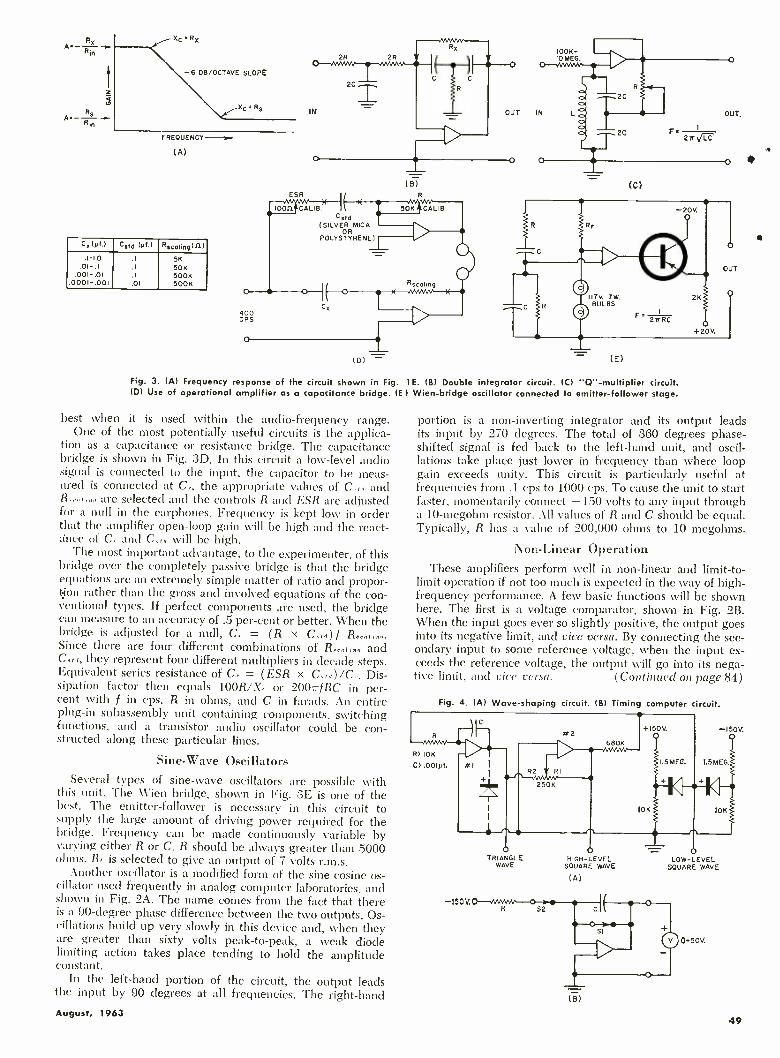
Re A :- - -
Rin
R S A.-
XC'RX
-6 OB/OCTAVE SLOPE
XC' RS
FREQUENCY -sue (A)
Cs(yf.) Cstd (Vf.) Rscalinq(n) .1-1.0 .1 5K
.01-.I .I 50K .001-DI .1 500K
.0001-.001 .01 500K
ESR
Cstd (SILVEORRMICA
POLYSTYRENE)
(B)
(D)
(C)
117V. 7W. BULBS
(E)
Fig. 3. (Al Frequency response of the circuit shown in Fig. 1E. (B) Double integrator circuit. (C) "Q "- multiplier circuit. (D) Use of operational amplifier as a capacitance bridge. (E) Wien- bridge oscillator connected to emitter- follower stage.
best when it is used within the audio -frequency range. One of the most potentially useful circuits is the applica-
tion as a capacitance or resistance bridge. The capacitance bridge is shown in Fig. 3D. In this circuit a low -level audio signal is connected to the input, the capacitor to be meas- ured is connected at C, the appropriate values of C.,,, and R..,.,...., are selected and the controls R and ESR are adjusted for a null in the earphones. Frequency is kept low in order that the amplifier open -loop gain will be high and the react- ance of C. and C.,,, will be high.
The most important advantage, to the experimenter, of this bridge over the completely passive bridge is that the bridge equations are an extremely simple matter of ratio and propor- tion rather than the gross and involved equations of the con- ventional types. If perfect components are used, the bridge can measure to an accuracy of .5 per -cent or better. When the bridge is adjusted for a null, C, _ (R x C.,,,) Since there are four different combinations of R and Ctd, they represent four different multipliers in decade steps. Equivalent series resistance of C., = (ESR x C,,1) /C,. Dis- sipation factor then equals 100R /X. or 200'.7fRC in per- cent with f in cps, R in ohms, and C in farads. An entire plug -in subassembly unit containing components, switching functions, and a transistor audio oscillator could be con- structed along these particular lines.
Sine -Wave Oscillators Several types of sine -wave oscillators are possible with
this unit. The Wien bridge, shown in Fig. 3E is one of the best. The emitter -follower is necessary in this circuit to supply the large amount of driving power required for the bridge. Frequency can be made continuously variable by varying either R or C. R should be always greater than 5000 ohms. Rr is selected to give an output of 7 volts r.m.s.
Another oscillator is a modified form of the sine -cosine os- cillator used frequently in analog computer laboratories, and shown in Fig. 2A. The name comes from the fact that there is a 90- degree phase difference between the two outputs. Os- cillations build up very slowly in this device and, when they are greater than sixty volts peak -to -peak, a weak diode limiting action takes place tending to hold the amplitude constant.
Li the left -hand portion of the circuit, the output leads the input by 90 degrees at all frequencies. The right -hand August, 1963
portion is a non- inverting integrator and its output leads its input by 270 degrees. The total of 360 degrees phase - shifted signal is fed back to the left -hand unit, and oscil- lations take place just lower in frequency than where loop gain exceeds unity. This circuit is particularly useful at frequencies from .1 cps to 1000 cps. To cause the unit to start faster, momentarily connect + 150 volts to any input through a 10- megohm resistor. All values of R and C should be equal. Typically, R has a value of 200,000 ohms to 10 megohms.
Non- Linear Operation These amplifiers perform well in non- linear and limit -to-
limit operation if not too much is expected in the way of high - frequency performance. A few basic functions will be shown here. The first is a voltage comparator, shown in Fig. 2B. When the input goes ever so slightly positive, the output goes into its negative limit, and vice versa. By connecting the sec- ondary input to some reference voltage, when the input ex- ceeds the reference voltage, the output will go into its nega- tive limit, and vice versa. (Continued on page 84)
Fig. 4. (A) Wave- shaping circuit. (B) Timing computer circuit.
-150V.
R> 10K
C> .001yf.
-{/ T
WI I
I +
-(50V.
TRIANGLE WAVE
HIGH -LEVEL SQUARE WAVE
(A)
LOW -LEVEL SQUARE WAVE
(B)
49

CATHODE-RAY
OSCILLOSCOPES
By EDWARD K. MARRIE Scientific Instrument Deot., DuMont Laboratories Divisions of Fairchild Camera and Instrument Corp.
One of the most useful and most versatile test instruments has made many advances in design and performance over the past decade.
INCE its commercial origin in 1932 the cathode -ray oscilloscope has become a primary instrument for
measuring electrical waveforms. It is used in a wide variety of fields and applications. Although oscilloscope man- ufacturers employ techniques that have brought the instru- ment from a simple indicator to a device that can measure electrical quantities accurately, the basic system concept has not changed. Exceptions are the new traveling -wave and sampling oscilloscopes which are special- purpose instruments.
Unlike many measuring devices, the cathode -ray oscillo-
scope enables rapidly varying analog information to be ob- tained. If the applied signals have random amplitude and time fluctuations, the oscilloscope must be employed. Scopes are multipurpose instruments combining features of both a.c. and d.c. voltmeters, ammeters, frequency and phase meters, waveform analyzers, and a good many more.
Types and Applications
Because it finds use in so many diverse measurement ap- plications, no one oscilloscope can contain all desired charac- teristics. If scopes were to be classified into three general groups, these would probably be: (1) general purpose, low - frequency, (2) general -purpose, high- frequency, and (3) special purpose.
Just what constitutes low and high frequency depends on
the range of frequencies required by industry at the time. In the early years of the oscilloscope, much of the electrical industry was concentrated in the area of a.c. power where scopes having bandwidths of only 10 kc. were sufficient. As
the radio industry began to grow, a need developed for oscilloscopes which could be used to check out carrier and audio channels, modulators, and discriminators. To make such measurements the bandwidth of the oscilloscope was pushed to 200 kc., a wide -band instrument around 1942.
Techniques developed for military systems during World War II were quickly adapted for scope circuitry to keep up with the expanding electronics industry. Distributed ampli- fiers began to replace the cascaded pentode amplifiers to fulfill the 10- to 20 -mc. requirements of post -war industry. Distributed amplifiers using tubes are now being phased out of newer equipment in favor of solid -state devices. High fre- quency in an oscilloscope today usually means 25 mc. or above. In two or three years this will probably be changed to 50 mc. or above.
The pressure for higher frequency instruments comes mainly from users and designers of advanced military systems and computer manufacturers. Already computers have reached a point where scopes with bandwidths of over 50 mc. are preferred in design work, or with 25 -mc. passband for servicing.
Oscilloscopes having low -frequency characteristics are still required in industry. Many applications where mechanical or hydraulic systems are involved need electrical test equip- ment having a bandpass of only 500 kc. This class of instru- ment has had a fairly constant market for the past -few years but does not have the growth potential of the high -frequency instruments used in the electronics field.
New and more sophisticated sweep circuits had to be de- veloped for the higher frequency instruments. Originally
One of the very earliest oscilloscopes was the Type 126, man-
ufactured in 1932 by the Allen B. DuMont Laboratories. Hav- ing developed a practical, long -lived cathode -ray tube, Dr.
DuMont's first use for these tubes was in instruments of this
type. The power -supply circuitry was in the cabinet shown while another cabinet, not shown, housed the sweep circuits
that were employed with the separately mounted CR tube.
50
An example of a high- sensitivity, general -purpose lab scope
is the Fairchild -DuMont 704. identical vertical and horizon- tal amplifiers are used with sensitivities of 0.2 mv. /cm. and bandwidths from d.c. to 500 kc. The triggered sweep is wide range from 0.1 µsec. /cm. to 1 min. /full scale. Critical dr- cuits use silicon transistors. The amplifiers are within ±10 relative phase shift to 100 kc. Price of the oscilloscope is $645.
ELECTRONICS WORLD

Designed for production and servicing of black- and -white and color -TV receivers is the RCA WO -91A. The scope can measure color -burst signals and can be used to troubleshoot wide -band color circuits. Either wide -band (10 cps to 4.5 mc.) or high- sensitivity (50 mv. p- p /in.) opera- tion is provided. Price of unit: $249.50.
Although most scopes use electrostatically deflected 5" tubes, the ITT LS -411 uses a magnetically deflected 14" CRT for display. With its plug -in amplifier and sweep modules, it can display low -fre- quency waveforms from d.c. to 25 kc. For use with analog computers and telemetry systems. Basic price, less plug -ins, $1965.
Another example of a general -purpose wide -band instrument designed mainly for black- and -white and color -TV servicing is the Jackson CRO -3. When switched to wide -band operation, the response is from 20 cps to 4.5 mc. When set for high sensi- tivity, 18 mv. r.m.s. signal produces a de- flection of 1 inch. Price of unit is $234.95.
saw -tooth sweep generators used thyratrons. These were free - running sweeps which could be locked to the synchronizing signal. Gas -tube sweep generators of this type had a maxi- mum repetition rate of about 40 kc., or a minimum sweep time of about 25 microseconds. To examine a 20 -mc. sine wave, a minimum of 0.1 µsec. or 100 nanoseconds was re- quired. More complicated and versatile saw -tooth generators such as the bootstrap and Miller integrator were devised.
In most present -day equipment, the Miller integrator is used because of its linearity and fast starting. The sync signal in this "triggered- sweep" system changes the state of a mul- tivibrator which starts the sweep. Another feature is that the method or mode of triggering may be altered. By changing the mode of operation, a triggered repetitive, free -running, single or automatic sweep may be obtained.
Single sweeps have become more important since the de- velopment of oscilloscope recording cameras where a tran- sient will start the sweep and activate the camera shutter at the same time. Triggered sweeps of this type produce linear sweeps of 5 nanoseconds.
To make scopes easier to operate, and due to the increased accuracy of the Miller sweep system (3 %), newer instruments are calibrated directly in time. At present, the Miller sweep generator is restricted to either electron -tube or hybrid cir- cuits. However, field -effect transistors, which are now becom- ing commercially available, will enable completely solid -state sweep generators to be built.
With the advent of pulse and digital circuitry, a new type of display was developed to single out and expand certain portions of a pulse train. At first it was sufficient to auto- matically change sweep rates during the sweep to produce a "notch." This notching technique, a forerunner of the delay- ing sweep, worked well for instruments which had a pass - band of 5 to 10 mc. As radar, pulse modulation, and com- puters became more refined and transportation of electrical information became faster, a new system was needed. It was important not only to know what pulse in a given train was being measured and its waveshape, but also its time relation to other waveforms in a system. To do all three jobs well, the modern delayed sweep was devised. Practically all missile projects require a number of scopes having delayed sweeps for systems check out.
Very accurate phase measurements at high frequency is another area which employs delayed -sweep scopes. In this method, a calibrated delay dial is used to measure phase.
Two types of instruments used for special high- frequency August, 1963
measurements are the traveling -wave and sampling oscillo- scopes. The traveling -wave scope has been designed for measuring very fast, single -shot or low- repetition -rate signals. Unlike the general- purpose scope, it does not have a vertical amplifier, but connects the signal directly to the CRT deflec- tion plates. Second, the vertical deflection plates are divided into sections to reduce the transit time of the electron beam through the plates. These various sections are connected to- gether with a delay line so that the signal progresses from one plate to the next in much the same manner as in a dis- tributed amplifier. This instrument, which is usually used with a camera, provides a means of recording very fast transients. Reduction in sensitivity and scan must be toler- ated in this system to achieve necessary bandwidth.
For higher bandwidths, a more versatile instrument, the sampling oscilloscope, may now be obtained. Using new solid -state components, sampling oscilloscopes will yield bandwidths over 1000 mc.
The sampling oscilloscope is closely analogous to a strobo- scopic light for visual observation of rapid motion. Both tech- niques appear to slow down motion and depend on repetition of the phenomenon to build up the apparent image. Sampling differs from conventional display in that for each occurrence of the input signal only a single point or sample of the input is displayed. The amplitude of this point is proportional to the signal amplitude at the instant of time the sample is made. By sampling at slightly different times for each input cycle, a display showing the entire waveform is produced. With this method, the effective bandwidth of a fairly low - frequency amplifier may be extended upward and the loss of sensitivity and scan in the traveling -wave system may be overcome.
Plug -in Units Not all improvements made to the oscilloscope have been
in the electrical circuitry. More versatility has been built into the scope by the use of various plug -in units. At first only vertical preamplifiers were available. These enabled the user to select vertical characteristics for a given application. A few years ago this was extended to both vertical and horizontal channels. Sampling generators were packaged as plug -ins to permit operation of specific instruments as both standard and sampling scopes. At present scopes may be obtained which have all of the signal circuitry contained in the plug - ins. Such instruments may now keep pace with the rigid specifications of present -day industrial and military applica-
51

Another example of a wide -band labora- tory oscilloscope is the Simpson 2610. This
instrument was designed to fill the gap between service -type scopes, which have fairly limited performance but at reduced cost, and the very high -performance, high - cost laboratory instruments. Response is
d.c. to 8 mc. ( ±1.5 db); sensitivity is 6
mv. r.m.s. /in. The price of the unit: $575.
In order to view waveforms with very short rise times, a high -speed sampling tech- nique is used in this Tektronix 661 with dual -trace sampling preamp unit. Small bits of the signal, sampled at slightly dif- ferent portions of the waveform, recreate the display. The vertical passband is equiv- alent to d.c. to 3500 mc.; rise time is 0.1 nsec. Price of scope and plug -ins: $3500.
An oscilloscope that uses an unusual CRT
to get a dual trace on the screen is the Telequipment (Avnet) D44. Although the tube uses a single cathode, control and focusing electrodes, two completely sep- arate deflection systems operate on the electron beam which is split in two parts. Plug -ins are available for various band- widths, gains. Price (basic unit): $350.
tions and yet provide maximum versatility for foreseeable future requirements.
As an example of improvements that have been made in
general- purpose low- frequency scopes in the past 10 years, let us compare some of the major characteristics of the DuMont Type 304 and the newer Fairchild -DuMont 704. The following table shows the improvement in the electrical
Characteristic 10- Year -Old New Oscilloscope Oscilloscope
Bandwidth Sensitivity Sweep Rate Phase Shift
Between X -Y Identical
Amplifiers Accuracy
100 kc. 100 mv. /div. 30 kc. Not Specified
No
±5%
500 kc. 0.2 mv. /div. 0.1 µsec. /div. ±10 to 100 kc.
Yes
-}2%
characteristics of the units. It should be noted that in the older instrument the sweep is calibrated in the number of
sweeps per second whereas in the newer type instrument
the horizontal axis is calibrated directly in time per division. The latest development in oscilloscope circuitry has been
the use of the transistor and other semiconductors. Although we know of no commercial oscilloscope that has been com- pletely transistorized, semiconductors are now used in from 30 to 90 percent of the active stages in some present -day instruments currently on the market.
Advantages of Solid -State Oscilloscope
Obvious advantages of solid -state design are that the in- strument will weigh less, require less space, and consume a
smaller amount of power. Instruments which have the same electrical characteristics as the solid -state oscilloscope weigh from 2.5 to 3 times more, and consume over twice as much power. Tube instruments exhibit two problems which are directly related to tube aging. There is a slow degradation in the tube parameters with time. This causes trouble in the calibration and balance of the instrument. Certain types of silicon transistors, on the other hand, retain their original properties for practically their entire life.
A special cathode -ray storage tube is the heart of the Analab Model 1220, shown here with a dual -trace plug -in preamp. In- formation can be stored for many months or it may be erased in 30 seconds. Repeti- tive signals up to 100 kc. and single tran- sients to several kc. can also be stored. Price of basic unit (no preamp) is $1600.
52
An example of an inexpensive general - purpose and service -type oscilloscope is
the Precision ES150. The unit can also be
used for low- frequency work as its re- sponse goes down to d.c. Or the high side response is -3 db at 4.5 mc. Sensitivity is 70 mv. /in. on d.c. and 25 mv. r.m.s./ in. on a.c. Price of the scope: $149.95.
Designed mainly for industria' applica- tions, such as general production testing, computer testing, and lab use, is the Hew- lett- Packard 175A. The scope has a pass - band of from d.c. to 50 mc. with 7 -nsec. rise time using a suitable plug -in preamp. A variety of vertical and time -base units are available. Price (basic uniti: $1325.
ELECTRONICS WORLD

The second effect which is found in tube instruments is a tube disease known as "cathode interface." This trouble is inherent in the vacuum tube itself and has been a constant, but unavoidable, source of trouble in high -frequency scopes until the introduction of the solid -state scope. When the tube begins to age, a resistance is developed between the heater and cathode of the tube. It acts as if an RC network had been connected inside the tube. This reduces the gain at low frequencies while not affecting the higher ones. A grad- ual overpeaking is therefore developed in the square -wave response. Some large companies connect clocks to their oscil- loscopes and replace all the tubes in the high -frequency amplifiers every 30 to 60 days. Since transistors have neither heaters nor cathodes, this problem is non- existent.
There is also more versatility when designing with tran- sistors, since both n -p -n and p -n -p transistors are available. The p -n -p transistor has no tube counterpart, since the tube would have to operate with the cathode positive with respect to the plate. In direct -coupled systems, this is an easy method of keeping the power supplies at low values.
Not all types of transistors are suitable for use in oscillo- scopes. To produce a stable, solid -state scope silicon tran- sistors are usually used. The reverse current from collector to base in transistors doubles every time the temperature in- creases 10 °C. Since the acceptable range of operation is be-
or not become obsolescent soon. These questions are general and could be used as a yardstick for either a scope to do a specific job, or one for general use.
1. What sweep rates are necessary? Some measurements require that the instruments have fast sweep rates, while others need slow sweeps. An oscilloscope having the greatest spread between fastest and slowest sweep would seem to be the more versatile. However, two important points should be considered in determining what sweep rates are necessary.
Are the frequency response of the vertical amplifier and the maximum sweep rate compatible and what is the se- quence of the sweep -rate switching? As a rule of thumb, if one cycle of the upper passband frequency can be displayed across the face of the CRT, then the sweep rate is adequate. For example, if the passband were 500 kc., then the period for 1 cycle would be 1 /500 kc. or 2 microseconds. If this time is divided by the number of divisions in the horizontal direc- tion, usually 10, then the fastest sweep rate required will be 0.2 microsecond per division. Applying this rule to a 25 -mc. bandwidth scope would yield the 4 nanosecond per division (4 nsec. /div.) sweep rate required. This sweep rate is not obtainable in high- frequency scopes at present and some other criteria are needed. The state of the art requires that a ratio of 5 to 1 will have to be used between the calculated sweep rate and what is available at the present time.
A 3 -inch d.c. oscilloscope that is avail- able in kit form is the Heath IO -10. Iden- tical vertical and horizontal channels are used with bandwidths from d.c. to 200 kc. Sensitivities of amplifiers are 0.4 v. (p -p) per inch. This compact scope weighs about 16 lbs. There is less than 5° relative phase shift between channels. Price: $79.95.
Another example of a scope in kit form is the Conar Model 250. This is a 5 -inch wide -band scope for general and TV serv- ice use. The vertical sensitivity of the unit is 23 mv. r.m.s. /in., and the ver- tical frequency response is flat from 13 cps to 2.5 mc. and down 1.5 db at 3.58 mc. Price: $89.50, or $139.50 assembled.
The most elaborate scope in kit form is the Knight 10 -mc. d.c. laboratory scope shown here. This is a research -quality unit with interchangeable vertical pre - amps. Built -in sweep timing markers are provided along with built -in voltage cal- ibrator. Dual -trace preamp is available. Price without plug -in preamps is $395.
tween 0 and 50 °C, an extremely low initial reverse current is a prime characteristic for transistors used in oscilloscopes. When germanium transistors are used, instability with tem- perature usually results due to their larger reverse currents.
Transistorized construction also makes it possible to pack- age all the signal -carrying circuitry into plug -ins rather than having it distributed between a preamplifier plug -in and the main frame. The delayed sweep generator, which contains two complete sweeps, may be operated more easily than tube types due to its compactness. Automatic features within this unit, made possible by silicon planar transistors, decrease the number of controls on the front panel. Cabling, which had to be external in the past, is now done internally and may be changed by means of front -panel switches.
Choosing an Oscilloscope When choosing an oscilloscope, there are certain questions
which must be answered to obtain an instrument that will avoid erroneous readings, make the required measurement, August, 1963
2. What is the accuracy of the sweep? If quantitative rather than qualitative information is required, the sweep accuracy timing should be no more than ± 5% from nominal. Most commercial manufacturers hold the tolerance to within 3% on all ranges.
3. Is vertical delay required? Above 5 mc. the oscilloscope should have a delay built into the vertical amplifier. An ex- ception to this is when using the instrument as an X -Y plotter where the sweep is inactive. Another application where a delay line is not necessary is when the scope is always trig- gered from an external source, which activates the sweep at a specified tinte before the signal applied to the vertical chan- nel. Such an application is the servicing of computers where the sweep is referenced to a given point in the computer and other signals measured from this point.
4. What rise time and bandwidth are required? Normally the rise time of the scope should be 1/5 the rise time of the signal being observed. This will cause an error of about 2% when making a rise -time measure- (Continued on page 74)
53

1963 Directory of Kit Test Equipment Complete listing of all presently available test equipment kits. Over 200
designs divided into 29 categories, according to function, are covered.
THE philosophy of producing kits is as old as the elec- tronics industry itself, but it wasn't until after World War II that test equipment in kit form was produced
in quantity. The advent of television generated an immediate need for test equipment for the installation, service, and maintenance of this new entertainment phenomenon. Not only were new forms of test equipment needed, but if rela- tively accurate and stable equipment could be produced at reasonable prices, there was a ready -made market for such output. Industry more than fulfilled its promise in the way of kits whose quality and low price far overshadowed the in- convenience of assembling such equipment. The fact that equipment had to be put together ultimately proved a real selling point since technically oriented persons derived tre- mendous satisfaction from building their own units.
Almost simultaneously with the service industry, a new market opened up in test equipment for the home workshop. Hobbyists, experimenters, and even electronics engineers, found test equipment kits the answer to their needs.
Today one can find test equipment kits in every area, from industrial and military plants to electronics laboratories. Serv- ice departments; production -line testing departments for radio, TV, hi -fi, and industrial electronic equipment; medical and educational institutions are among the diversified places where such test equipment can be used. Test equipment kits have become so sophisticated that in many cases they are the equal of all but highly elaborate and specialized factory -as- sembled units. In laboratories, once they have been checked against calibrated equipment, they are ideal for making com- parative measurements on all types of products.
Kits have achieved these advances for several good rea- sons: (1) Design standards, component quality, and accu- racy are relatively high. (2) Technicians can assemble them during free time while drawing regular salary. In this way key employees can be kept busy without additional cost. (3) One of the most important reasons why kit test equipment has made inroads in the industrial area is that their circuits can be modified during construction to adapt the instrument to special applications. In many cases there is a need for specific individual tests, especially for production applica- tions. Why tie up multiple -operation units in such cases?
Today, kits bear little resemblance to the first 5" scope kit that sold for $39.95 in 1947. Circuit design, performance, and versatility of present -day test equipment have kept pace with the industry. Transistors are now beginning to replace vacuum tubes in some kits.
Over 200 different test equipment kits are available rang- ing in price from $5.50 for a capacitor substitution box to $395.00 for a laboratory oscilloscope. There is actually no limit to the degree of complexity of the test equipment that can be designed and marketed in kit form. Why this is so is
largely a matter of the painstaking detail and clarity of the construction manuals accompanying such equipment.
If you have never assembled a kit, be assured that these manuals are well written with step -by -step instructions so
clearly presented that an operating instrument is guaranteed. Calibration procedures are simple and provide a relatively high degree of accuracy. Should problems arise, manufac- turers will, for a nominal fee, check out any kit that does not operate, calibrate it, and put it in top working order.
R.F. SIGNAL GENERATORS
Mfgr. Model Freq. Range
(fundamentals) No. of Bands
Cal. Harmonics Output Modulation Freq. (cps)
Provision for
Ext. Mod.
Audio Output Price Remarks
Freq. No. of Bands
Voltage Z Volts
ALLIED 83Y953 160 kc. -112 mt. S none - .4 - 400 yes yes 10 $19.95
CONAR 280 170 kc. -60 mc. 6 none - .1 502 400 no yes 5 $21.50
EICO 315 75 kc. -50 mc. S 13 -150
mc.
2 .1 - 400 yes yes - $49.95
320 150 kc. -34 mc. 5 22 -102
mc.
2 .1 - 400 no yes 1.5 -2 $24.95 Model 322 with 5 cal.
bands $27.95
324 150 kc. -145 mc. 6 111 -435
mc.
1 .1 502 400 yes yes 10 $28.95
EMC 502 115 kc. -110 mc. 6 - - .1 - 400 yes no - $17.95
HEATH FM0 -1 90, 100, 107 mc. 3 - - - - 400 no yes - $34.95 three switch -selected freq.
var. 10.7 mc. sweep, 200 kc.
to over 1 mc., 10.7 mc.
crystal mark. 100 kc.
submarker
IG -42 100 kc. -31 mc. 5 - - .1 502 400 yes no - $56.95 panel meter indicates output voltage or percent
modulation
15 -102 100 kc. -110 mc. 6 110 -220
mc.
1 .1 5012 400 yes yes 10 $27.95
LAFAYETTE KT -208 250 kc. -120 mc, 5 - - - - 400 yes - - $19.95 also a signal tracer
OLSON KB -141 250 kc. -120 mc. 5 - - - - 400 yes - - $19.95 also a signal tracer
PRECISE 610K 300 kc. -110 mc. 5 60 -330
mc
2 - - 60, 400 - - - $27.50 available with precali-
brated r.f. head as
610KA, $34.95
RADIO SHACK
22 -068E 100 kc. -330 mc. 6 - - 1.0 - 20- 20,000 yes 20.
20,000 cps
2.5 $39.95 meter indicates r.f., a.f.
output; r.f., a.f. volts;
db in 3 ranges;
0 -1, 10, 100 v. a.c.
22 -026 5 - - .1 502 400 yes - - $18.95 160 kc. -110 mc.
ELECTRONICS WORLD 54

TUBE TESTERS
Mfgr. Model
Type Tests
G,,,
Line - Voltage Adjust Charts *Sockets Meter Scale
Special Tube Tests Price Remarks
Emission G.
-
Shorts, Opens, Leakage
Grid Current
ALLIED 4004 X
X
shorts
only
X
book 7- 8 9 -pin minis- tore, oc., lok.
good -bad - $ 19.95
600B X roll
roll
4, 5, 6, IL, 7S,
oc., lok, 9, com.,
nov., nov., 10
good -bad CRT with adapter $ 39.95 counter model $35.95
performs gas check
CONAR 221 X Shorts,
opens,
leakage
X
X 4, 5, 6, IL, 7 -, 9 -,
10 -pin miniature, oc., lok., nov.,
corn., 5 -, 7 -pin nuv.
CRT with adopter,
VR, tuning eyes
$ 48.75 12 test levers,
book for foreign tubes
EICO
EMC
625 X X X roll 4, 5, 6, 7L, 75,
oc., Ink. nov.
good -had VR's, "eye," CRT
with adapter
S 34.95
628
666
667
X X X
X
roll
roll
7-9- 8 10 -pin miniatures; oc.,
lok., 5- 8 7 -pin
nuv., tom., nov.
VR's "eye" color &
monochrome
CRT's with adapter
$ 44.95
X 4, 5, 6, 71, 7S,
miniature 7- 8
9 -pin, subminiature 5, 6, 7 -pin (in -line base), oc., tek.
good -bad CRT with adapter, VR's,
"eye," ballast tube
S 69.95 direct indication of
leakage in ohms;
transistor leakage and
beta test
X
X
X
X X X roll 7 -9- 8 10 -pin miniatures; 5 -6- 8
7 -pin sub -miniature, sub -miniature 8-
pin, oc., lok., 5- 8
7 -pin nuv., cam.,
n^v.
VR's, "eye" ballast, color 8
monochrome
CRT's with adapter
S 19.95 direct indication of
leakage in ohms;
transistor leakage and
beta test
205 X X roll 9 sockets good -bad "eye," VR, CRT
with adapter S 34.50
209 X
X
X
X
book 7- 8 9 -pin minis- tore, oc., lok.
good -bad CRT with adapter $ 25.90 rejuvenates CRT's
211
213
301
book 7- 8 9 -pin minia-
tyre, oc., lok.
good -bad - $ 14.90
X X
X
X
book 7- 8 9 -pin minis- tare, corn., nuv.,
nov., 10 -pin, oc., lok.
good -bad VR's, "eye" $ 18.9C $21.90 in wood
carrying case
X book 7- 8 9 -pin minio- ture, oc., lok.
good -bad CRT with adopter S 32.60 $33.20 in wood
cabinet; rejuvenates CRT's
302 X book 7- 8 9 -pin minis- tore, oc., lok.
good -bad CRT with adapter $ 47.90 $49.90 in wood
cabinet; rejuvenates CRT's
HEATH TT -21 X X
X
X
X
X roll 4, 5, 6, 71, 7S,
7, 10 -pin minia-
ture, oc., lok., nov., cam., 5, 7-
pin nuv.
good -bad CRT with adapter $ 44.95
TT -1A
KT -209
1/4 Ira. sensitivity
X X roll 4, 5, 6, 71, 7S,
7- 8 8 -pin sub-
miniature, oc., lok., 9 -pin miniature, tom., nuv., nov., 10 -pin
0 -3000 ¡mhos, VR test volts,
0 -1 v. a.c.
VR's, low -power
thyratrons, "eye" tubes
$149.95
LAFAYETTE X book 7 sockets good -bad $ 17.95
OLSON KB -142 X book 7 sockets good -bad S 17.95
PACO T -60 X X X roll 7- 8 9 -pin minia- tore, ac., lok.
good -bad VR's, "eye," CRT with adapter, gas rectifiers
S 42.95
T -62 X X X book 7, 9 8 10 -pin miniature, 12 corn.,
5- & 7 -pin nov., oc., lok, nov.
good -bad CRT with adapter S 49.95 has 0 -1000
VTVM megohmmeter
for external checking resistors,
capacitor leakage, etc.
RADIO
SHACK
22 -064M X X X roll 4, 5, 6, 71, 7- 8
9 -pin miniature, oc., lok., com.,
nuv., 10 -pin
good -bad CRT with adapter $ 44.50
22 -2001E X X X X roll 4, 5, 6, IL, 7S,
7 subminiature, oc., lok., 8-
subminiature, 9- 8
10 miniature, nov., nov., corn.
good -bad
0- 30,000 limbos
$ 94.50 tests transistors & zener
diodes; fil. current indi- toted on meter
*corn. = compactrons; nuv. = nuvistors nov. = novar; oc. = octal; lok. = loktal.
August, 1963 55

OSCILLOSCOPES
Mfgr. Model
Vertical Channel Horizontal Channel
Sweep Ste Price Remarks Freq. Resp. Sensitivity (meg. pf) Freq. Resp. Sensitivity (meg.-pf.) pf)
ALLIED 83Y1;913 5 cps -5 mc.
13 db
25 r.m.s. mv. /in. 3.4 -12 down 4 db
@ 1 mc.
600 r.m.s.
mv. /in. - 15 cps-
600 kc.
5" $ 69.95
83YZ945 - - - d.c. to 2.5 mc.
+0 -3 db
.1 v. /cm.- 1. v. /cm.
- .5 sec. /cm.- 50 nsec./ cm.
5" $395.00 intensity modulated
time marks ® 10,
100, 8 1000 µrev. 83Y2946 differential amp, for 83YZ945: vert. chan. freq. resp. d.c. -100 kc., 0 to -3 db; sensitivity, 1 p.p.v /in.; inpu 3, 1 meg., 40 pf. S 59.95 5000:1 diff. ratio
83YZ948 dual -trace preamp for 83YZ945: vert. chan. freq. resp. d.c. -10 mc., 0 to -3 db; sensitivity 50 p.p.mv. /cm.; input Z, 1 meg., 40 pf. $ 79.95 switching rate: 100
kc. chopped or
alternate sweeps
83Y11910-
-1
d.c. -5 mc.
+0, -3 db
d.c.- coupled .05 v.
p- p /cm.; a.c.- coupled
.005 v. p -p /cm.
1 -40 d.c. to 500 kc.
+0, -3 db
.15 v. /cm. has variable aftenuator
1 .05 sec. /cm.- 200 nsec. /cm.
5" $184.95 85 nsec.
use time
CONAR 250 flat 13 cps-
2.5 mc., down
3.5 db @ 4.5 mc.
.023 r.m.s. v. /in. 2.7 meg. @
1 kc.
flat 23 cps -90 kc.
down 3 db
@ 250 kc.
1 r.m.s. v. /in. 4.9 meg.
@ 1 kc.
10 cps-
500 kc
S" S 89.50 built -in pulse for flyback, yoke tests,
etc.
EICO 427 d.c. -1 mc.
± 0, -6 db
10 p -p mv. /cm. 1 -30 2 cps -450 kc.
+0, -3 db
.5 p -p v. /cm. 10 -40 10 cps.
100 kc.
5" S 69.95
430 2 cps -500 kc.
+0, - 3 db.
25 r.m.s. mv. /cm.
1 -30 2 cps-300 kc.
+0, -3 db
.25 r.m.s. v. /cm.
:0 -40 10 cps-
100 kc.
3" S 65.95
460 flat d.c. -4.5 mc.
down 10 db.
@ 10 mc.
25 r.m.s.
mv. /in. 3 -35 flat 1 cps -400 kc. .6 r.m.s. v. /in. 5-35 10 cps-
100 kc.
5" S 89.95 .06 µsec. rise time
FEILER TS -7 20 cps -75 kc. .5 r.m.s. v. /in.
1 -50 - .5 r.m.s. v. /in. 1 -50 10 cps-
32 kc.
S" S 53.48
HEATH l0 -i0 d.c. -100 kc.
(2 db point)
.1 p -p 0.11/4" 3.6 -35 same as vert. same as vert. 3.6 -35 5 cps-
50 kc.
3" S 79.95
10 -21 2 cps -200 kc.
2 db
.25 r.m.s. v. /in. 10 -20 same as vert. same as vert. 10 -20 20 cps-
100 kc.
3" S 49.95
10.12 3 cps -5 mc.
+1.5 db
to - 5 db
.025 r.m.s.
v. /in. @ 1 kc.
3.3 -12 1 cps -400 kc.
±3 db
.3 r.m.s. v. /in. @ 1 kc.
4.9 @ 1 kc. 10 cps-
S00 kc.
5" S 76.95 .08 /met. rise time 2 preset sweep
freq. positions
PACO S -51 5 cps -1.2 mc.
=3 db, to 2 mc.
±6 db
90 r.m.s. mv. /in. 1.5 -25 16 db to
700 kc.
250 r.m.s. mv. /in. 10 -25 20 cps-
150 kc.
5" $ 69.95
5 -55 a.c. 8 d.c. within 5 db @ 5 mc.
25 r.m.s. mv. /in. 1.5 -23 within 3 db 1 cps
400 kc.
.6 r.m.s. v. /in. 5 -23 10 cps -100 kc. 5" 5 95.95 .08 µsec. rise time
PRECISE 300K d.c. -5 mc.
=3 db
3.9 p -p mv. /cm. - - - - 1 cps -80 kc. 7" 5169.95
308K d.c. -5 mc.
1.5 db
10 p -p mv. /cm. - - - - 1 cps -80 kc. 81/2" S179.95
315K a.c. coupled
within +6 db
to 500 kc.
250 mv. /in. - - 250 mv. /in. - 10 cps-
100 kc.
5" S 59.95
3151K flat to 5 mc. 10 mv. /cm. - - 10 mv. /cm. - - 5" S 69.95
RCA WO -33A flat 5.5 cps-
5 mc. within -3 db
.3 p -p v. /in. 1 -50 flat 3.5 cps-
350 kc. within --6 db
.9 r.m.s. v. /in. 10- 15 cps -75 kc. 3" S 79.95 wideband response
.1 //sec. rise time
3 cps -1.S mc. flat within - 6 db
.01 p -p v. /in. 1 -50 flat 3.5 cps-
350 kc. within -6 db
.9 r.m.s. v. /in. 10- 15 cps -75 kc. 3" S 79.95 narrow band
response
.1 µsec. rise time
RADIO
SHACK
22 -072E 10 cps -3 mc.
±5 db to 5 mc.
100 r.m.s. mv. /in. single trace;
200 r.m.s. mv. /in. dual trace
500 k. single
trace; 100 k
dual trace
flat to 100 kc.
-6 db @ 1 mc.
100 r.m.s. mv. /in. - 10 cps-
100 kc.
5" 5 69.95
22 -086E d.c. -75 kc. 25 r.m.s. mv. /in 5 -100 20 cps -70 kc. .6 r.m.s. v. /in. .5 -100 20 cps -20 kc. 3" 5 34.50
TRANSISTOR TESTERS
Mfgr. Model Tests
Voltage -Current Ranges
Price Remarks Shorts Gain Leakage
Forward &
Reverse Current
ALLIED 83Y149 X X S 8.95 checks leakage -to -gain ratio
checks diodes 8 rectifiers
EICO 680 X d.c. beta directly -2 -30, 2 -300
a.c. beta indirectly I,:,,, I,,,, X 50, 500 µa., 5, 50,
500 ma.
$25.95 d.c. voltage ranges 5, 50 v.; three
res. ranges, 2000, 200 k, 20 meg.;
checks diodes 8 rectifiers
EMC 212 d.c. in three ranges to 200 X 80 ma., 12 v. $13.50 checks transistors as a.c. current
amplifiers 8 in- circuit
HEATH IM -30 X d.c. beta directly 0 -300
d.c. alpha directly 0 -.9967
l,;,,, I,, 15, 150 µa., 1.5, 15, 150
ma., 1.5, 15 a., 1.5, 5, 15,
50, 150 v. (100 k ohms /volt)
$54.88 collector current to 15 a.;
provision for external d.c. supply;
checks diodes 8 rectifiers
IT -10 X ., X X S 6.95
LAFAYETTE KT -223 d.c. in 3 ranges to 200 X 83 ,:,a., 12 v. $12.75 in- circuit transistor checks
include power types
56 ELECTRONICS WORLD

Study for a profitable career ...in the place you like best!
LET RCA TRAIN YOU IN ELECTRONICS
LOS ANGELES
-111111
Prepare yourself for a profitable future in the ever -growing field of electronics while enjoying the advantage of the city you prefer. Whether you study at the RCA Institutes in Los Angeles or in New York City, you'll be getting the finest of training in electronics. RCA Institutes is recognized throughout the United States as a leading technical institute devoted exclusively to electronics. You have a broad selection of courses to choose from ... each one the finest of its kind ... each one preparing you for an exciting career in the fascinating field of electronics.
Coeducational day and evening courses start 4 times each year
SEND COUPON FOR FREE RESIDENT SCHOOL CATALOG
Home Study Courses also available. Catalog free on request. For further information see our Home Study ad on Page 11.
For Los Angeles School send this coupon. i RCA INSTITUTES, INC. A Service of Radio Corporation of America
The Most Trusted Name in Electronics
r For New York School send this coupon.'
610 S. Main St., Dept. EWR -83 Los Angeles 14, Calif. Please send me your FREE catalog of Resident School courses.
Name
350 West 4th St., Dept. EWR -83 New York 14, N. Y.
Please send me your FREE catalog of Resident School courses.
Name
Address
(please print)
Address
(please print)
City Zone State City Zone State
August, 1963
L 57

1963 KIT TEST EQUIPMENT DIRECTORY Continued
GENERAL PURPOSE V.T.V.M.'s
Mfgr. Model
Ranges*
No. of Ranges
D.C. Input Res. (meg.)
A.C. Input Z
(meg: pf.)
Accuracy (full -scale)
Frequency Response Price Remarks **
D.C., A.C. (r.m.s.)
Ohms/ mid -scale D.C. A.C.
ALLIED 83Y911 1.5 -1500 1000 /10 1000m./10m.
7 11 - y 3% ±5% 30 cps -5 mc.
±3 db.
$26.95 db range -10 to + 65;
a.c. p -p ranges 4, 4000
ARKAY VT -10 3 -1500 1000, 1000m. 7 11 - - - 30 cps -5 mc. $25.95 db range -10 to + 58
CONAR 211 3 -1200 1000/10 1000m. /lOm.
6 12.2 1.5- ± 2% ± 3% 30 cps -6 mc. $31.95 uses switchless single
probe lead
DEVRY - 1 d.c., 5 a.c.- 1000
100 /100k. 4 ranges
4 10 1.85- - - - $64.50 d.c. current
50 -500 ¡La., 5 -50ma.
transistorized, battery
operated
EICO 221 5 -1000 1000, 1000m. 5 25 3- 13% ±5% 20 cps -200 kc. $25.95 db range -20 to + 55
214 - - - - - $34.95 same as 221 but 71/2" meter
222 3 -1500 1000m. 5 11 1- ±13% ± 5% 30 cps -3 mc. $27.95 p -p with special prohe
'32 1.5 -1500 1000m. 7 - - - - 30 cps -3 mc. $29.95 a.c. p -p ranges 4, 4200
19 - - - $39.95 same as 232 but 71/2" meter
EMC 06 1.5-1000 1000, 1000m. 5 16.5 2- - - 25 cps -100 kc. $23.90 db range -24 to + 55
107 1.5 -1000 1000, 1000m. 6 16.5 1.5- - - - $34.50 a.c. p -p ranges 4, 2800;
capacity SO pf. -5000 µf.; inductance
1.4- 140,000 hy.
107A - - - - - - - - $36.50 same as 107 but 6" meter
FEILER TS -9 5-1000 1000m. 5 26 3- ± 2% = 2% - $26.39 db range -20 to + 16;
0.1 ma. d.c. range
HEATH IM -13 1.5-1500 1000 /10 1000m. /10m.
7 11 1 -30 ±3% ±5% 25 cps -1 mc.
+1 db
$32.95 db range -10 to + 65
IM -1I 1.5-1500 1000 /10 1000m. /lOm.
7 11 1 -35 =F 3% =5% 25 cps -1 mc. ±
1 dh
$24.95
LAFAYETTE KT -174 1.5 -1500 1000, 1000m. 7 11 150 v. -1.3 meg;
500 e.,1500 v. -1.5
meg; other scales
50 -83 meg.
±2'/, ±5% (5e.)
±3% (others)
20 cps -4 mc.
±1 db
$44.50 'ow a.c. ranges 50, 150,
500 mv.; 4.2, 4200 p -p
ranges
KT -202 3 -1500 1000 /10 1000m./10m.
7 11 - - - 30 cps -5 mc. $25.95 db range -10 to + 18;
a.c. p -p ranges 8, 2000
OLSON KB -140 3 -1530 1000 /10 1000m. /lOm.
5 11 - - - 30 cps -5 mc. $25.95 db range -10 to + 58;
a.c. p -p ranges 8, 2000
PACO V-70 1.5 -1500 1000 /10 1000m./10m.
7 11 - - - 40 cps -4 mc.
= 1 db
$31.95 db range -6 to + 66;
a.c. p -p ranges 4, 4000
PRECISE 904K 1.5 -1500 1000 /10 1000m./10m.
7 - - - - - 439.95
909K 5.1000 1000 /10 1000m./10m.
5 25 - - - - $29.95
9071K S -1000 1000 /10 1000m. /10m.
5 25 - - - - $39.95 P /z" meter
RADIO SHACK
22 -070M 1.5 -1500 1000 /10 l000m./10m.
6 11 - ±3% ±5% flat to 2 mc. $38.20 15, 150 mv. ranges;
.15, 5 a. a.c. ranges;
0 -1600 w. a.c. ranges
15, 30, 60 watts across
16, 8, 4 ohm lends
22 -078 3 -1500 1000 /10 1000m. /10m.
11 - `3% ±5`/, flat to 3 mc. $26.95 db range -10 to + 38;
a.c. p -p ranges 8, 2000
RCA WV -77E 1.5 -1500 1000 /10 1000m./10m.
i 11 - =3,0 =5% 40 cps -5 mc.
±5 db on
1.5, 5, 15
v. ranges
$29.95 a.c. p -p ranges 4, 4000
WV -98C .5 -1500
d.c.
1000, 1000 . 7 11 .83 -70 ±3% ±3% ( ±5 %, 1.5-5v.)
30 cps -3 mc. $62.50 a.c. p -p ranges 4, 4200
.5 v. d.c.range
Figures are highest scale markings for lowest and highest ranges.
* *Peak -to -peak ranges, where shown, are true readings of comp'ex waveshapes.
A.C. POWER SUPPLIES GRID -DIP METERS
Mfgr. Model Output Voltage
Output Current
Meter Ranges Price Mfgr. Model ; Range (me.) No. of Bands
Power Prüce Remarks V. A.
EICO 1073 0 -140 1, 3 a. 140 1, 3 $35.95 ALLIED G-30 1.5 -300 6 a.c. $22.95
1078 0 -140 2.5, 7 a. 140 2.5, 7 S42.95
HEATH IP-22 90-130 in
.75 v. steps
300 w. (cont.)
500 w. (inter.)
90 -140 $54.95 EICO 710 .400 -250 8 O.C. $29.95
RADIO
SHACK
22 -902E 0 -150 5 a. 0 -150 $20.21
HEATH HM-10A 3 -260 6 bail. $34.95 tunnel diode
58 ELECTRONICS WORLD

D.C. POWER SUPPLIES C t Id s) C irren a I6GO a m
Mfgr. Model Voltage Ranges
p meter Scales
Price Remarks Continuous Intermittent
ALLIED 83YX912 8, 15 15 (6 v.)
10 (12 v.)
17.5 (6 v.)
12.5 (12 v.)
15 v. d.c.
20 a. d.c.
$38.95
EICO 1020 6, 30 150 ma. (0 -12 v.)
200 ma. (12 -24 v.)
300 ma. (24 -30 v.)
6 v. d.c.
30 v. d.c. $23.99 .005% 120 cps ripple at full load
1050 8, 16 10 (8 v.)
6 (16 v.)
20 (8 v.)
12 (16 v.)
20 v.
20 a.
$29.95 not recommended for transistor work; accessory
filter 41055 available
1060 8, 16 10 (8 v.)
6 (16 v.)
20 (8 v.)
10 (16 v.)
20 v.
10, 20 a.
$39.95 ripple 16 v. range: 3% @ 2 a., 1% @ 6 a., 1.5% @ 10 a.;
8 v. range: 1.5% @ 2 a., 2% @ 6 a., 4.5% @ 10 a.
1064 8, 16 10 (8 v.)
6 (16 v.)
20 (8 v.)
10 (16 v.)
20 v.
10, 20 a.
$45.95 ripple same as 1060; lightweight version of 1060
EMC 905 6, 12 - - 2 meters $28.90 with extra filtering for transistor applications $34.90
HEATH IP-12 8, 16 10 (6 v. unfiltered) 5 (6 v. filtered) 5 (12 v.)
15 (6 v. unfiltered) 1.5 (12 v. unfiltered)
2 meters $47.50 ripple .3%
IP -32 0 -400 v.
0 to 100 v.
(bias voltage)
100 ma.
1 ma.
125 ma. 150, 400 v.
150 ma.
$56.95 6.3 v. @ 4 a. a.c. output; ripple 10 mv. d.c. output
impedance 10 ohms; output regulation 1% from no load to full load, -`-= .5 v. for * 10 v. lin= vattene variation from 117 v.
IP -2D 0 -50
in 5 v. steps
1.5 - 15, 50 v.
& amp.
$72.50 transistorized, ripple & noise 150 µv. max., overload
protection, load regulation = 15 mv., output imp.
.01 ohm to 10 kc. - .5 ohm 10 kc. & up
PACO B -10 8, 16 10 (8 v.)
6 (16 v.)
20 (8 v.)
12 (16 v.)
2 meters $43.95 low ripple output; 8 & 16 v., 5 a., 3%
B.12 0 -400 v.
0 to - 150 v.
150 ma.
2 ma.
- 150, 400 v.
200 ma.
$69.95 6.3 v. ® 3 a. and 12.6 v. @ 3 a. a.c. outputs; d.c. output
impedance 10 ohms; regulation .33% from no load to full load; .4% for ± 10 v. line voltane variation from 117 v.
PRECISE 711 15 v.
30 v.
110 -180 v.
10
10
.750
20
20
1
- - $59.95 90 -140 v. a.c. (isolated) output @ 1 a.; Model 713 90 -140 v.
a.c. @ 3 a. output $69.95; other a.c. output on both models:
24 v. @ 20 a., 90 -140 v. @ 10 a. continuous (not isolate'',
760 140 -450 v.
0- ± 1000 v.
Cd 1 ma.
100 ma. - 2 meters 549.95 6.3 v. @ 4 a. and 375 v. ® 50 ma. a.c. outputs; ripple .01
SIGNAL TRACERS
Mfgr. Model Indicators Test Speaker
Function Out. Trans.
Function Wattmeter Function
°B +" Output
Component Noise -Test Function
Price Remarks Speaker I Eye
ALLIED 83Y955 X X X X X X X $26.95
CONAR 230 X X $39.95 calibrated attenuator for r.f.
& a.f. gain measurement, tuned
& calibrated 175 kc. to 1500 kc.
in two bands
EICO 145A X X X X X $23.95
147 X X X X X X $29.95
EMC 802 X X X X X $24.95 generates 400 cps and
modulated 455 kc. signals
FEILER TS -1K phone $ 7.76 meter, phone, battery extra
TS -3K X $26.16 can he used to convert v.o.m. to r.f. v.t.v.m.; battery operated
TS -2K S17.95
TS -5K X S23.52 can be used to convert v.o.m. to
r.f. v.t.v.m.
HEATH 1T -12 X X X X X X $19.95
LAFAYETTE KT -208 X $19.95 also signal gen., see listing; output for v.t.v.m. & phones
OLSON KB -141 X $19.95 I also signal gen., see listing
PACO Z -80 X X X X X $32.95 calibrated attenuator for
gain measurement
SWEEP AND MARKER GENERATORS
Mfgr. Model Freq. Range No. of Bands
Output Sweep Width
Cal. Marker Ranges (fund.)
No. of Bands
Provision for Marker Crystals
Provision for Ext. Markers
Price Remarks Voltage Z
ALLIED 83YX123 300 kc. -250 mc. 4 .15 0 -13 mc. - - 2 yes $44.95
EICO 360 500 kc. -228 mc. - - - 0 -30 mc. - - 1 no $39.95
368 3 -216 mc. 5 I - 502 0 -15 mc. 2 -225 mc. 3 1 yes $69.95
369 3.5 -216 mc. 5 50$2 20 mc. 2 -75 mc. to 225
mc. on harm.
3 fund. 1 harm.
1 no $79.95 post marker
adder
HEATH I6 -52 3.6 -220 mc. 4 .1 502 0 -42 mc. 19 -60 mc. 1 1 yes $54.95
PACO G -32 3 -220 mc. 5 - - 0 -20 mc. - - 1 yes $85.95 marker adder
August, 1963 59

1963 KIT TEST EQUIPMENT DIRECTORY Continued
AUDIO GENERATORS
Mfgr. Model Range No. of Output Output
Waveforms Accuracy Y Distortion Price Remarks Max. Volts Loads
ALLIED 83YX137 20 cps -1 mc. S 10 600 sine - .25% from 100 cps through audible range into h gh Z
535.95
EICO 377 20 -200 k (sine)
60 -50 k (square)
4 10 1000 sine -square ±3% less than 1% $37.95
HEATH IG -72 10 cps -100 kc. sw. sel.
freq. 1 v.
10 v.
600
10,000
sine ±5% less than .1% from 20.20,000 cps
$41.95 output meter calibrated in volts and db
IG -82 20 cps -1 mc. 5 10 v. (sine Si
square)
high I sine -square ± 1.5 db
TO cps -1 mc.
.25% from 20- 20,000 cps $51.95 square -wave output voltage is
p -p; rise time .15 µsec. PACO G -34 6 cps -750 kc. 6 10 v. (sine)
18 v. (square)
600
600
sine -square - -- S64.95 square -wave output voltage is
p -p; rise time .15 psec. PRECISE 635 20 cps -200 kc. S - - sine -square - - -- $39.95
630 20 cps -20 kc 5 - -- sine - - - $44.95 has additional r.f. band .3 mc. -Poll mc.
A.C. V.T.V.M.'s
Mfgr. Model Range*
A.C. (r.m.s.l v. No. of
Ranges A.C. Input Z
lmeg. -pf.) Accuracy (full- scale)
Frequency Response Price Remarks
ARKAY AV -20 .01 -300 10 1 meg. @ 1 kc. - 10 cps -400 kc. -4-: 1 db
(.01-100 v. range)
10 cps -40 kc. ±2 db
(300 v. range)
$29.95 db range -52 to + 52
AW -30 5 mw. -500 w. 6 4, 8, 16, 600 ohms - 10 cps -250 kc. ± 1 db $29.95 audio wattmeter 25 w. con-
tinuous, 50 w. intermittent EICO 250 .001 -300 12 10 -15 ±3% 10 cps -600 kc. ±0 db $49.95 amp. output 5 v.;
max. gain 60 db 255 .001 -300 12 10 -15 -!-3% 10 cps -600 kc. ±0 db $44.95 db range -80 to + 52 261 .01 -1000 11 2 -15 ± 4% 10 cps -150 kc. ± 0 db $49.95 wattmeter ranges (7)
.15 mw. -150 w.; -
loads: 4, 8, 16, 600 ohms
@ 40, 80, 40 + 40 walls HEATH IM-21 .01 -300 10 (10 -300 v.) 10 -12
(.01 -3 v.) 10 -22
=5% 10 cps -500 kc. ±1 db
10 cps -1 mc. ±2 db
$33.95 db range -50 to + 53
RADIO
SHACK
22.027
(TX -111)
.01 -300 10 1 @ 1 kc. - 10 cps -400 kc. ±1 db
(.01 -100 v. range)
10 cps -40 kc. ±2 db
(300 v. range)
$25.95 db range -52 to + 52
'Figures are highest scale markings of the lowest and highest ranges.
CAPACITOR CHECKERS
Mfgr. Model Out or In- Circuit
Check
Capacitance Test
Range
Resistance Test
Range
Power-Factor Function
Test Voltages Tests
Price Remarks Shorts Open
ALLIED 83Y952 in 20 pf.- 2000 µf. X X $14.95
83Y901 out 10 pf. -1000 µf. 100 ohms-5 m. 0 -50% 50, 150, 250, 350, 450 volts d.c.
X X $19.95
ARKAY CA -40 out 1 pf. -1 µf. $29.95
CONAR 311 out 10 pf. -1500 uf. 1 ohn -150 m. 0 -50% 0 -450 volts d.c. X X $21.95
EICO 955 in .1 µf. -50 pf. 6.3 v. a.c. to 2000 µf. from
5 pf.
$19.95
EMC 801 in 10 pf.- 5000 µf. .5 ohm -500 m. 0 -60% 0 -500 volt d.c. to 20 µf. from
50 pf. $24.95 will not check electrolytics
for short
HEATH II -22 in to 20 µf. from
50 pf. $10.95
IT -11 out 10 pf.- 1000 µf. S ohms -50 m. X 3 -600 v. d.c. X X $29.95 direct reading scales; input
provision for 10 kc. signal
PACO (.20 nut 10 pi. -201,0 µf. .5 ohm -200 ni. 0 -60% 0 -500 v. d.c. X X $23.95 bridge circuit far determining transformer turns ratio
C -25 in 2 µf.- 400 ¡cf. X from 5 pf.
$19.95
RADIO
SHACK 22 -088 n 4 pf.-400 µf. X X $19.95
60 ELECTRONICS WORLD

NEW ALL -TRANSISTOR ALL -MODE TUNER -
by HEATHKIT
new Heathkit AM -FM- STEREO transistor tuner kit $11995
THE LATEST IN FEATURES: 24 transistors, 9 diodes Built -in stereo circuitry Auto-
matic stereo indicator Automatic switching to eliminate manual switching to receive stereo Built -in Automatic Frequency Control and Automatic Gain Control Ad- justable FM squelch Stereo phase control Filtered stereo tape recorder outputs Built -in AM & FM an- tennas Separate AM & FM tuning meters Lighted slide -rule dial Flywheel tuning Regulated power sup- ply Factory assembled FM tuning unit and 4 -stage IF circuit board Concealed secondary controls behind hinged lower front panel
FREE HEATHKIT CATALOG Fully describes over 250 ex- citing, easy -to -build Heath - kit products for Stereo /Hi- Fi, Amateur Radio, Test, Marine, Educational, and Home Entertainment. See how you can save up to 50% on equipment and have fun doing it! Send for your free copy today!
It's new, it's deluxe, and it's all transistor! That's the Heathkit AJ -43 Trans- istor Tuner featuring the very latest in solid -state circuitry for more features, greater listening pleasure. Sensitive, automatic, and ready to capture any broadcast your choose ... up -to- the -minute AM ... beautifully quiet FM ... and thrilling, natural FM Stereo! Truly deluxe ... styled in tasteful tan vinyl - clad steel to complement any decor, quietly ... to match other deluxe Heath - kit stereo equipment. If you prefer the finer things, the latest in the state of the art you'll love the Heathkit AJ -43! Kit AJ -43, 18 lbs., no money down, $11 mo $119.95
Matching All- Transistor Stereo Amplifier For balanced performance and appear- ance, choose the Heathkit AA -21 . 28 transistors, 10 diodes, 70 watts! 28 lbs. Kit AA-21, $13 mo. $139.95 Assembled AAW -21, $16 mo. $167.95
Enclosed is $ plus post- age, please send Model AJ -43 Transistor Tuner
Enclosed is $_plus post- age, please send Model AA- 21 Transistor Amplifier
Please send FREE 100 page Heathkit Catalog
HEATH COMPANY Benton Harbor 15, Michigan
Name
Street
City Zone State
August, 1963 CIRCLE NO. 122 ON READER SERVICE PAGE 61

1963 KIT TEST EQUIPMENT DIRECTORY Continued
V.O.M.'s
Mfgr. Model
Ranges* No. of Voltage Ranges
Sensitivity ohms /volt
Accuracy Price Remarks A.C. -D.C. Ohms/
mid -scale D.C. Current
tA.C. Current O.C. A.C. D.C. A.C.
ALLIED 83Y128 1 -5000 1000 /60 a.c. & d.c. 7 1 k 1 k =2% - $15.95 db scale -20 to + 69;
100,000 /150 1, 10, 100 ma., 1 a.
1 meg. /1500
83Y149 same as 128 but with 5% resistors $13.95
83Y140 2.5 -5000 2000/12 .1, 10, 100 ma., 6 20 k 5 k ±2 % - 529.95 db scale -30 to + 63;
200,000/1200 1, 10 amp. output function
20 meg. /120 k
83Y708 5 -500 30 k /1200 5, 10, 100 mn. 5 1 k - - - S 7.95
15 -500 (a.c.)
ARKAY M4 1 -5000 55- 150.1500 a.c. & d.c. 7 1 k 1 k - - $13.50 db scale -20 to + 69;
1, 10, 100 ma., 1 a. in 6 ranges
MT -50 1.5 -5000 15- 150 -15 k 150 ua, 15, 150, 500 7 20 k S k - - $29.50 db scale -12 ma., 15 a. d.c. to + 65 db
CONAR 240 6 -600 1000, 10 m. - 3 20 k 5 k ±3% ±5% 517.95
EICO 536 1 -5000 5000, 1 m. a.c. & d.c. 7 1 k 1 k - - 519.95 db scale -20 to + 69;
1, 10, 100 ma., 1 a. with 1% res. Model 526
565 2.5 -5000 2000, 20 ns. 100 pa., 10, 100, 500 6 20 k 5 k - - $24.95 db scale -12 to + 55;
ma., 10 a. output function;
with 1% res. Model 555
566 1 -5000 5000, 1 m. 1, 10, 100 ma., 1 a. 7 1 k 1 k - - $16.95 db scale -20 to + 69
output function; with 1% res. Model 556
EMC 102K 6 -3000 1000, 1 m. 6, 30, 130 ma., 1.2 a. 5 - - =2% =2% $12.50
12 -3000 (a.c.) t30, 150, 600 ma.
103K 6 -3000 1000, 1 m. 6, 30, 120 ma. 5 - - - $14.90 db scale
t30, 150, 600 ma.
109K 6 -3000 20 k -20 m. 6, 60, 600 ma.; 5 20 k 10 k - - $19.25 db scale
12 -3000 (a.c.) (3 ranges) t30, 300 ma., 3 a.
HEATH IM -20 15 -500 - 1 ma. 4 1 k - ± 10% - $14.95 cap. & res. substitutions;
(d.c. only) signal generator
HM -1 1.5 -5000 -20 m. 150 pa., 15, 150, 7 20 k 5 k - - $29.95 db scale -10 to + 65;
500 ma., 15 a. output function; polarity rev. switch
LAFAYETTE TK -10 10 -1000 10 k, 1 m. 500 pa., 10, 250 ma. 5 20 k 10 k - - $11.95 db scale -20 to + 36;
PACO M40 1.5 -6000 2000/8.5 60 ILO., 1.5, 15, 150 7 20 k 10 k - - $31.95 db scale;
3 -12k (a.c.) 20 m. /85 k ma., 1.5, 15 n. output function
RADIO 22 -079 1 -5000 1000 -1 m. a.c. & d.c. 7 1 k - - - $16.95 db scale -20 to + 69
SHACK 1, 10, 100 ma., 1 n. output function
RCA WV-38A .25 -5000 2000/12 50 pa., I, 10, 100, d.c. -8 20 k 5 k ±3% =5% $29.95 db scale -20 to +50; 2.5 -5000 (a.c.) 20 m. /120 k 500 ma., 10 a. a.c. -6 output function;
polarity rev. switch
'Fleurer are h' ^hest sca'e r arkinps for lowest and highest ranges.
CAPACITOR & RESISTOR SUBSTITUTION & DECADE BOXES
Mfgr. Desistance Capacitance
Model Range (ohms) Steps Decades Tolerance Wattage Range Steps Decades Voltage Rating Tolerance Price
ALLIED 83Y138 - - - - - .0001 uf.- .22 cif.
18 - 600 v., .15 & .22
cif. are 400 v.
±20% $ 5.95
83Y139 15 -10 k
15 k -10 m.
18
18
- =10% - - - - - - $ 5.95
EICO 1100 15 -10 m. - multiples of
15, 22, 33, 47,
68, 100 ohms
=10% 1 - - - - $ 7.95
1120 - - - - - .0001 pf.- .22 uf.
18 - 600 v. =10% 5 6.95
1140 - - - - - - - - - $14.95 (com-
bination of
1100 & 1120)
1171 0- 99,999 1 ohm 5 t /p% 1 - - - - $24.95
1180 - - - - - 100 pf.- .111 pf.
100 pf. 3 350 v. =10% $17.95
EMC 900 15 -10 m. 2 - =10% 1 .0001 pf.- .22 sf.
18 - - - $10.25
HEATH IN -22 - - - - - .0001 pf.- .22 pf.
18 - 600 v., 400 v. for
three highest steps
$ 5.50
IN -21 - - - - - 100 pf.- .111 uf.
100 pf. 3 - ±1% $17.95
IN -11 1- 99,999 1 ohm 6 ±s /z% - - - - - - $24.95
IN -12 15 -10 m. 36 - ±.10% 1 - - - - - $ 5.95
62 ELECTRONICS WORLD

Ilil Stereo Review
STEREO TEST RECORD FOR NOME AND LABORATORY USE LIMA: AS A DEMONSTRATION OF TE WRIEST POSSIBLE FIDELITY. THIS RECORD INCLUDES A
PROGRAM Co. MUSIC RECORDED DIRECTLY ON THE MASTER. WITH NO INTERVENING TAPE PROCESS
Why We Make the Model 211
Available Now Although there are many stereo test records on the mar- ket today, most critical checks on existing test records have to be made with expensive test equipment.
Realizing this, HiFi STEREO REVIEW decided to produce a record that allows you to check your stereo rig, ac-
curately and completely, just by listening! A record that would be precise enough for technicians to use in the laboratory -and versatile enough for you to use in your home.
The result: the HiFi STEREO REVIEW Model 211 Stereo Test Record!
Stereo Checks That Can Be
Made With the Model 211 Frequency response -a direct check of eighteen sections of the frequency spectrum, from 20 to
20,000 cps.
Pickup tracking - the most sensitive tests ever available on disc for checking cartridge, stylus, and tone arm.
Hum and rumble -foolproof tests that help you evaluate the actual audible levels of rumble and hum in your system.
Flutter -a test to check whether your turntable's flutter is low, moderate, or high.
Channel balance - two white -noise signals that allow you to match your system's stereo channels for level and tonal characteristics. Separation -an ingenious means of checking the stereo separation at seven different parts of the musical spectrum -from mid -bass to high treble.
Stereo Spread
ALSO : U Speaker Phasing
Channel Identification
PLUS SUPER FIDELITY MUSIC! The non -test side of this record consists of music re- corded directly on the master disc, without going through the usual tape process. It's a superb demonstration of flawless recording technique. A demonstration that will amaze and entertain you and your friends.
August, 1963
NOW...GET THE FINEST
STEREO TEST RECORD ever produced
for j Featuring Tests Never Before Available
Outside Of The Laboratory UNIQUE FEATURES OF HiFi /STEREO REVIEW'S
MODEL 211 STEREO TEST RECORD
Warble tones to minimize the distorting effects of room acoustics
when making frequency- response checks. Warble tones used are recorded to the same level within _
I db from 40 to 20,000 cps, and within 3 db to 20 cps. For the first time you can measure the frequency response of a system without an anechoic chamber. The frequency limits of each warble are within 5 % accuracy.
White -noise signals to allow the stereo channels to be matched in
level and in tonal characteristics.
Four specially designed tests to check distortion in stereo cartridges.
Open -air recording of moving snare drums to minimize reverberation
when checking stereo spread.
All Tests Can Be Made By Ear HiFi STEREO REVIEW's Model 211 Stereo Test Record will give you immediate answers to all of the questions you have about your stereo system. It's the most complete test record of its kind -contains the widest range of check -points ever included on one test disc! And you need no expensive test equipment. All checks can be made by ear!
Note to professionals: The Model 211 can be used as a highly efficient design and measurement tool. Recorded levels, frequencies, etc. have been controlled to very close tolerances -affording accurate numerical evaluation when used with test instruments.
DON'T MISS OUT- SUPPLY LIMITED The Model 211 Stereo Test Record is a disc that has set the new standard for stereo test recording. Due to the overwhelming demand for this record, only a limited number are still available thru this magazine. They will be sold by ELECTRONICS WORLD on a
first come. first serve basis. At the low price of $4.98, this is a value you won't want to miss. Make sure you fill in and mail the coupon together with your check ($4.98 per record) today.
FILL IN AND MAIL TODAY!
Stereo Test Record
Electronics World -Dept. SD
One Park Ave., New York 16, N.Y.
Please send me test records at $4.98 each. My check (or money order) for $ is enclosed. I understand that you will pay the postage and that each record is fully guaranteed.
Name (Please Print)
Address
City Zone State EW 83 SORRY -No charges or C.O.D. orders!
63

1963 KIT TEST EQUIPMENT DIRECTORY Continued
UNCLASSIFIED TEST EQUIPMENT Audio Analyzer
Heath: Model IM -22, $56.95. a.c. v.t.v.m. freq. resp. 10 cps -100 kc. ± 1
db; range .01, .03, .1, .3, 1, 3, 10, 30, 100, 300 r.m.s. v.; input impedance 1 meg. or 4, 8, 16, or 600 ohms. Wattmeter: 10 cps -50 kc. ±
1 db.; .15, 1.5, 15, 150 mw., 1.5, 15, 150 w.; 4, 8, 16, 600 ohm internal loads, 10,000 ohms across external load. IM ana- lyzer: high -pass filter, 2000 -12,000 cps, low -pass filter 10 -600 cps; 1, 3, 10, 30, 100 per -cent full scale. Input impedance a.c. v.t.v.m., 1 meg. or 4, 8, 16, or 600 ohms switch -selected. Internal - generator frequencies: 60 cps, 6 kc. DBM: -40, - 30, - 20, -10, 0, 10, 30, 40, 50. Reads from -65 +52 db-n. Accuracy: a.c. v.t.v.m. and wattmeter within 5% full -scale; IM analyzer within 10% of full -scale.
Battery Tester Eico: Model 584, $9.95. Test positions (volts): 1.5, 4.5, 6.0, 7.5, 9.0,
22.5, 45, 67.5, 75, 90, spare.
CRT Checker Eico: Model 630, $19.95. Bridge circuit measures peak beam current.
Model 632, $54.95. Checks for opens, shorts, beam current, gas.
Uses 1000 v.d.c. for rejuvenate -welding and to remove shorts.
Paco: Model T -63, $44.95. Checks screen brightness under high or low line voltage conditions; simulates the effect of a booster; can be used as a rejuvenator. Beam current type test circuit.
Bar and Dot Generators Eico: Model 352, $19.95. TV channels 2 -6; 16 -23 vertical bars, 13 -22
horizontal bars; output voltage .4 mv.
Heath: Model IG -62, $64.95. TV channels: 2 -6. Output voltage 100- 100,000 uv. Sound carrier: crystal -controlled, unmodulated, 4.5 mc. away from picture carrier. Positive or negative video output variable from 0 -10 v. p -p open circuit. Modulation: white -dot pattern, cross -hatch pattern, horizontal bars, vertical bars, 10
vertical color bars, shading bar pattern. Paco: Model G -36. $119.95. Produces color bars, white dots, vertical
bars, horizontal bars, and crosshatch. Crystal controlled.
Electronic Switches Eico: Model 488, $23.95. Switching rate 10 -2000 cps continuously
variable in 3 ranges. Frequency response d.c.- 30,000 cps ( -2 db); maximum gain 10 times (continuously variable gain control); input -impedance 100,000 ohms; max. input at greatest attenua- tion 400 v. p -p; output impedance 50,000 ohms.
Heath: Model S -3, $23.95. Freq. resp. to 100 kc. -!- 1 db.
Filament Tester Eico: Model 612, $4.95. Checks filament continuity. Sockets are pro-
vided for 9 pin, octal, ooctal, and 7 and 9 -pin miniature tubes.
Adapter provided for checking 14 -, 12 -, and 8 -pin picture tubes.
Flyback Transformer and Yoke Testers Allied: Model 83Y118, $21.95. Indicates shorts in coil with a "Q" greater
than 1, and inductance from .0003 -2 hy. Checks continuity of circuits with 0 -.5 meg. resistance.
Eico: Model 944, $23.95. Checks all flyback transformers and yokes in- or out -of- circuit.
Harmonic Distortion Meter Heath: Model IM -12, $54.95. Frequency 20- 20,000 cps in three ranges;
distortion 1, 3, 10, 30, 100 per -cent full -scale; voltmeter 1, 3, 10, 30 volts full- scale; input resistance 300,000 ohms; minimum input voltage for distortior measurements 0.3 v.; output voltage for monitoring 2.5 at full -scale meter reading. Meter scales cali- brated in volts r.m.s., per -cent distortion, and db. When used with Heathkit IG -72 or IG -82, the IM -12 will measure harmonic distortion at any frequency between 20 and 20,000 cps.
Impedance Bridges Eico: Model 950, $23.95. Measures capacity from 10 pf. -5000 pf.
in four ranges, resistance from .5 ohm -500 meg. in four ranges. Comparator ratio from .05 -20 (400 to 1). D.c. polarizing voltage 0 -500 v.
Heath: Model IB -2A, $69.95. Measures resistance from .1 ohm -10 meg., capacitance from 100 pf.- 100 µf., inductance from .1 mhy. -100 hy., dissipation factor ,002 -1, storage factor ( "Q ") .1 -1000. Built -in 1000 cps generator and provision for input from external gener- ator.
Paco: Model C -20, $23.95. Capacitance 10 pf. -2000 µf. in four ranges, resistance .5 ohm -200 meg., capacitor leakage test at 500 v. Ratio tests from .05 -1 and 20 -1 on capacitors, inductors, and resistors; power factor range from 0 -60% at .1 µf.- 2000 µf.
Q Meter Heath: Model QM -1, $54.95. Frequency: 150 kc. -18 mc. in four bands.
Inductance: 1 phy. -10 mhy. "Q "; 250 full scale x 1 or x 2. Capaci- tance: actual, 40 pf. -450 pf.; effective, 40 pf. -400 pf.
RF Power Meter Heath: Model PM -2, $12.95. Frequency range 100 kc. -250 mc , sensitivity
.3 v. r.m.s. at antenna input terminals for full -scale deflection.
Vibrator Tester EMC: Model 906, $17.05. Checks 6- and 12 -volt vibrators with external
power supply. Six sockets. The Model 905 -6A, a combination of the 906 and the 905 battery eliminator, costs $44.90.
Voltage Calibrators Allied: Model 83Y136, $12.95. .01 -100 v. square -wave output. Eico: Model 495, $19.95. Semi -square (clipped sine -wave) output wave -
shape at line frequency. 0 -.1, 0 -1, 0 -10, 0 -100 p -p v. Dial reading accuracy ± 5 %.
Manufacturers of Kit Test Equipment
Allied Radio Corp.
100 N. Western Avenue
Chicago 80, Illinois
Arkay International, Inc.
2372 -82 Linden Blvd.
Brooklyn 8, N.Y.
Conar Instruments Div.,
National Radio Institute 3939 Wisconsin Avenue
Washington 16, D.C.
DeVry Technical Institute 4141 Belmont Ave.
Chicago 41, III.
Eico Electronic Instrument Co., Inc.
3303 Northern Blvd.
Long Island City 1, N.Y.
EMC Electronic Measurements Corp.
625 Broadway
New York 12, N.Y.
Feiler Engineering & Mfg. Co.
8026 N. Monticello Avenue
Skoie, Illinois
Heath Company
Benton Harbor, Michigan
Lafayette Radio Electronics Corp.
111 Jericho Turnpike
Syosset, L.I., N.Y.
Olson Electronics, Inc.
260 S. Forge Street
Akron 8, Ohio
Paco Electronics Co., Inc.
70 -31 84th Street
Glendale, L.I., N.Y.
Precise Electronics & Development Corp.
76 E. Second Street
Mineola, L.I., N.Y.
RCA: Radio Corporation of America
415 S. Fifth Street
Harrison, New Jersey
Radio Shack Corp.
730 Commonwealth Avenue
Boston 17, Mass.
64 ELECTRONICS WORLD

Two outstanding products by the HIDDEN 600 who plan for your future:
DIFIIM od`dBtbula° CAPACITORS
ORANGE DROP®
dipped tubular CAPACITORS
TWO GREAT TUBULARS ... TAKE YOUR CHOICE! (± 105,, Capacitance Tolerance is standard at no extra cost)
Sprague Difilm Capacitors can't be beat! Dual- dielectric con- struction combines the best features of both Mylar polyester film and special capacitor tissue. And for additional reliability, Difilm capacitors are impregnated with Sprague's HCX" , a solid impreg- nant which produces a rock -hard capacitor section -there's no wax to drip, no oil to leak!
BLACK BEAUTY Molded Tubulars are actually low -cost versions of the famous Sprague high- reliability capacitors used in modern military missiles. They're engineered to withstand 105 °C (221 °F) temperatures ... even in the most humid climates! And their tough, molded phenolic cases can't be damaged in handling or soldering.
t ORANGE DROP Dipped Tubulars are the perfect replacement for radial -lead capacitors now used by leading manufacturers of TV sets. Leads are crimped for neat mounting on printed wiring boards. Extremely small in size, they'll fit anywhere, work anywhere. And they're double -dipped in epoxy resin for extra protection against moisture.
'-The "Hidden 600" are Sprague's 600 experienced researchers who staff the largest research organization in the electronic component industry and who back up the efforts of some 8,500 Sprague employees.
Get your copy of Catalog C -614 from any Sprague distributor, or write Sprague Products Co., 51 Marshall Street, North Adams, Massachusetts.
G.-_,,a_ WORLD'S LARGEST MANUFACTURER OF CAPACITORS August, 1963 CIRCLE NO. 138 ON READER SERVICE PAGE
SPRAGUE® THE MARK OF RELIABILITY
65

Mac and Barney discuss tite practical and philosophical considerations in servicing transistorized equipment.
SEMICONDLTCT()R SEMINAR
STOPPING short in the doorway of the service depart- ment, Barney did an exaggerated Jackie Gleason double -take of Mac, his employer.
since when dici you take up welding ?" he demanded, looking curiously at the strange black object jutting from Mae's forehead and covering his eyes.
"These aren't welding goggles," Mac explained, pushing the object up on his forehead a bit and peering from beneath ii at his assistant. "It's a "Magna- Sighter," manufactured by the Fairchild Optical Company in Chicago. It's really a binocular eye loupe with a magnification of 2!t times. A prism is ground into each magnifying lens so that the eyes can converge at the proper focal distance. In this particular model, Model 5, that's ten inches; but they make other models that focus all the way from fourteen inches to four inches -from the eyes, not the lenses. Magnification in other models ranges from IN tines to 33 tines, with the greater magnification having shorter focal distance and also less depth of focus."
"How come the lenses are so far from the eyes? They must be at least a couple of inches in front of them."
"For one thing, that allows you to wear glasses, even bi- focals, with the `Magna -Sighter.' The instrument is adjusted so that the bottoms of its lenses are directly in line with the eyes. When you look up slightly, you peer through the upper section of the bifocals and the 'Magna-Sighter' lens. When you glance down, you see through the lower section of the bifocals as you do normally. Here, see for yourself."
Barney adjusted the headband to accommodate his slightly larger head and took a look at the printed circuit of a tran- sistor radio.
"Wow!" he exclaimed. "That certainly makes things stand out sharply. The joints look kind of 3 -ll, if you know what I mean."
"I know. It reminds nie of the way things used to look through the old stereoscopes every proper family kept in the front parlor. It gives you an almost exaggerated impression of depth."
"This thing is going to be the old berries for working on transistor sets," Barney exclaimed enthusiastically. "I can even read that postage -stamp -sized diagram pasted in the cover. I thought our jeweler's loupe and our illuminated magnifier were good, but this gadget has some definite ad- vantages. For one thing, my unaristocratic eye gets tired of trying to hold that loupe in place like a monocle. Too, I have to take it out every time I want an unmagnified view of things. With this, I simply lower my head for a magnified view and raise it to see normally."
"If it helps your young eyes that much, think what it does for these tired old orbs," Mac suggested. "Transistor radios and accompanying printed circuits have really placed a premium on good eyesight. Visual inspection alone can spot many difficulties in these receivers. It used to be a technician's joke that customers were always suspecting a `loose connec-
66
tion' or a `broken wire.' These faults were actually rarely found in wired- chassis tube radios, but they account for a high percentage of difficulties in transistor receivers, prob- ably because these little hand- carried receivers are more often dropped and subjected to other abuse. But a hairline crack in a printed circuit or a tiny break in a solder joint of one of these miniature receivers is darned hard to see."
"You're in phase there," Barney agreed. "The first thing I do after I've checked out the battery of a transistor set is to give it a really good looking over, no matter if the complaint is a dead radio, weak reception, distortion, or what have you. This eyeball inspection very often saves a lot of time. Of course, through experience, I've learned certain spots are hotbeds for these cracked- joints- and -broken -lead troubles.
"One good hunting place is where a comparatively heavy component is soldered to the board. This includes trans- formers, tuning capacitors, and occasionally speakers. A heavy impact that occurs when the radio is dropped is likely to break either the soldered connection to the component or the printed circuit in the vicinity of that component. A cracked board, naturally, usually means one or more broken leads. Sometimes rough handling of the tuning control knob or the volume control knob is all that's needed to fracture the board. I might mention the modern tough plastic used in the cases of these little receivers won't tattle on the owner for dropping his set. A jar that really messes things up in- side often fails to leave a telltale mark on the case."
"Yes, and isn't it strange how reluctant most customers are to confess the set has been dropped? Either they must think we automatically up the bill when we hear the radio has been dropped, or they simply don't want to admit to having but- terfingers. Wonder if you've noticed leads running along the edge of a printed circuit -quite often such leads are a part of the set ground system -are especially likely to develop hairline cracks. I suppose this is because the edge of the board is subjected to more flexing."
"I sure have," Barney agreed, "and a crack in one of these leads will often leave the set dead as a mackerel. Other spots I favor with close attention are those where wire leads con- nect to the printed circuit, especially if those leads are likely to be subjected to some pulling and bending. Battery leads are a good example. So are antenna leads, speaker leads, and leads going to the earphone jack. Some of these are sub- jected to stress simply by careless removal of the back of the case and changing the batteries; others have strain put upon them in the assembly of the receiver."
"I find a surprising number of sets in which those little hair -like leads from the antenna are broken off," \ -Iac com- mented. "Apparently the owner doesn't see them when he's changing a battery and accidentally breaks them loose. I
might mention it's much easier to break one of these leads off than it is to find quickly where that lead originally con- nected to the printed circuit, especially if the receiver is an import for which we have no diagram. I'm hoping the
ELECTRONICS WORLD

`Magna- Sighter' will be a help in locat- ing that little stub of broken wire stick- ing up out of a solder joint.
"Getting away from broken leads," Barney said, "I've decided that when the service data calls for a matched pair of transistors in the output stage and one of them goes bad, it's usually better to replace both with another matched pair. I've tried using a single general replace- ment transistor for the bad one, and it will work after a fashion, but checking the outputs of the two transistors with a v.t.v.m. reveals they are seldom close to equal. When the transistors have sockets and you have a good supply of substitutes On hand, you can try them one after the other and may find one that will match closely the one in the set; but if the transistors are soldered in, it's better not to fool around. .just remove both and put in a new matched pair."
"Those foreign imports for which 1ve have no service (lata are a real pain," Mac mused; "but electronics tnagazines are doing their best to help. I cut out and save the pages giving American substitutes for foreign transistors and the names and addresses of importers who can furnish service data and special parts for the brands they import. Even so, when a customer insists on a pre- liminary estimate on one of these, I make it good and stiff to protect myself. I know from experience I'm likely to spend twice as much time locating the trouble as would be the case with an American -made receiver for which we have complete and detailed service in- formation."
"You remember Dave, the salesman who used to call on its from Electronic Equipment," Barney said. "I ran into him at a lunch counter yesterday, and he tells me he's doing a good business servicing transistor radios for radio and TV shops. Most of the big TV shops con- sider transistor radio service a 'nuisance' business; yet they have to do it; so they're glad to give the work to Dave. He charges a flat five dollar service fee per set, no matter what's \vron <g with it. Parts, of course, are extra. He says Ire's doing very well and has all the business he cams handle. FIe says he turns out the sets faster and faster as he gains ex- perience."
"Sure he does, and he's a lot smarter than the fellows for whom he is work- ing," AIac replied. "They are paying him to acquire experience they should be getting themselves. It doesn't take a seventh son of a seventh son to see that eventually transistors are likely to re- place tubes in almost all household elec- tronic equipment. They have a lot of things going for thons: small size, long life, little heat, high efficiency, and small - size - low - voltage accompanying components. When transistorized TV August, 1963
NEW CADRE C -75 CB TRANSCEIVER The new Cadre C -75 1.5 -watt 2- channel transceiver is 15 times too powerful for youngsters (under 18 years of age) to oper- ate, according to FCC regulations. Clearly, it's not a toy. Its designed for serious CBers who need 'big set' performance that can be used conveniently anywhere. The new C -75, weighing less than 2 lbs; pro- vides clear, reliable 2 -way communications up to 5 miles and more. All solid state design creates an extremely rugged transceiver to absorb rough handling, stays on frequency. Two crystal -controlled channels_ spell per- fect communications contact everytime. Sen- sitive superhet receiver (lay for 10 db S/N ratio) brings in signals in poor reception areas. Powerful transmitter has one watt output to the antenna. Adjustable squelch silences receiver during standby. AGC as- sures proper listening level. In a word, the C -75 has all the features you'd look for in a quality full size CB unit. The C -75 has all the portable conveniences: operates on alkaline or mercury penlite cells (8 -hour rechargeable nickel- cadmium bat- tery available) ; earphone and antenna jacks; built -in retractable antenna; jack for base
operation while recharging;. Use the Cadre C -75 anywhere in the field, for vehicle, office, boat or plane. Use it con- stantly too, because its all- transistor modu- lar circuit(11 transistors and 2 diodes) is vir- tually maintenance free. $109.95. Recharger and 2 nickel- cadmium batteries $31.85. FOUR CADRE 5WATT ALL.TRANSISTOR TRANSCEIVERS
O O 5 crystal-con- , trolled transmit
and receive posi- tions; automatic gain control, maximum re- ceiver sensitivity; built -in squelch and noise limiting are just a few of the features. CADRE 510 Variable tuning in addition to crys- tal control. Power supply for 110 VAC and 12 volt DC. $209.95 CADRE 515 Power supply for 110 VAC and 12 volt DC. $194.50 CADRE 520 For DC mobile operation and fleet use. $187.50 CADRE 525 In portable case with built -in bat- tery power supply, recharger, AC cord, tele- scoping antenna. $269.95
See your Cadre distributor or write:
v CAC - E INDUSTRIES CORP. /COMMERCIAL PRODUCTS DIV. /ENDICOTT, N. Y. /(607) 748 -3373 Canada: Tri -Tel Assoc., Ltd., 81 Sheppard Ave. W., Willowdale, Ort. Export: Morhan Exporting, 458 B'way, N. Y. 13
CIRCLE NO. 106 ON READER SERVICE PAGE 67

TEXAS HCC: J
^// CHECK
CITIZENS -BAND TRANSMITTERS
¡till At AA INEXPENSIVE -ONLY S260.00 NET.
EVERY CB CLUB SHOULD HAVE ONE.
CALIBRATIONS FREE FOR ALL 23 CB CHANNELS WITH NEW METER.
PORTABLE AND RUGGED -WEIGHS 8 LBS.
ACCURACY BETTER THAN 0.0025 %. AMPLE FOR CB.
WITH THE
LAMPKEN 105 -B
FREQUENCY METER
FLEXIBLE-CAN BE USED FOR OTHER MOBILE - RADIO MEASUREMENTS FROM 100 RC TO 175 MC AND UP. NO ADDITIONAL CRYS- TALS OR FACTORY ADJUSTMENTS EVER NEEDED FOR OTHER FREQUENCIES. TIME PROVED DEPENDA- BILITY. THOUSANDS IN USE -SINCE 1938.
TO LEARN MORE, AND HOW YOU CAN EARN MONEY CHECKING FREQUENCIES FOR OTHERS...
MAIL COUPON TODAY!
r LAMPKIN LABORATORIES, INC. MFM Division, Bradenton, Florida At no obligation to me, please send free booklet "HOW TO MAKE MONEY IN MOBILE -RADIO MAINTENANCE" and data on Lampkin meters.
NAME
ADDRESS
CITY STATE
THE MOST WIDELY USED MOBILE -
RADIO FREQUENCY METER-
THE LAMPKIN 105 -B
LAMPKIN LABORATORIES, INC.
MFM Divisioi BRADENTON, FLORIDA
CIRCLE NO. 125 ON READER SERVICE PAGE
ELECTRONICS' & TV TECHNICIANS! "It's Got To Be In Your Pocket!"
MINITEST I, a transistorized blocking oscillator for every electronics technician or engineer. Handy
signal transmitter for finding defective circuits in
LF, IF and HF oscillatory circuits, transformers
and chokes as well as in sound pick -ups and
transmitters of all types... .
SAY YOU SAW IT IN
Electronics World
Send for NEW FREE CATALOG :952
with oscillator circuits
and its Twin: MINITEST II, a transistorized blocking oscillator for every TV Technician. A
signal generator for finding defective circuits in
VHF and UHF tuners and converters, as well as
video i.f. and output stages. Can also be used
as bar pattern or net pattern generator. EACH TWIN:
-is the size of a ball -point pen -is switched on & off like a ball -point pen
-weighs less than I oz. -works on a 1.5 V battery -is guaranteed for six months -is imported from Germany (W)
MINITEST I Net $7.95 MINITEST II Net $8.95 TWIN -MINS (I & II if purchased together) Net $16.53
Clip coupon and moil with check or Money Order. We pay the postage- Sorry, no COD shipments.
AZTEC ENGINEERING COMPANY P.O. Box 158, Lebanon, N.J.
Nane
Address:
Dealer & Jobbers' inquiries invited. J CIRCLE NO. 143 ON READER SERVICE PAGE
68
Citizen Band $295 Class "D" Crystals
CITIZEN BAND CLASS "D" CRYSTALS rd
u` ertone - .005(6 tolerance - te ,till FCC
r equirements. Hermetically
Baled HCIt /C holders. 'z' pin spacing. .050 pins. (Add 15e per crystal for .VV gins).
All IJ mEgiievaile fret! uonei es in mot.), s,
Matched crystal sets for Al.' . CB units (Specify equipment make and nudet numbers)
-- - -- - -- - -- ..$5.90 per set
RADIO CONTROL CRYSTALS in HC6 U HOLDERS -SIX FREQUENCIES
In ,9. I, r Ì, ,c,li alo Jv l: cony ifrcgncfl: ( hard Ia :, .elos vii oralle,, .uo ' ; i'.." pin spacing. l in , t i.0. +:5 pins available, add Tse per
crystni., Suetiify freguenc desired. 26.995, 27.045, 27.095, 27.145, $ 27.195, 27.255....... ......... ' ACCH (add SC per crystal for postage- handlIng)
ENGINEERING SAMPLES and small in :entities for prototypes it' at either Chicago to Fort Myers plants with 24 hour
.c.vitc. IN CHICAGO. PHONE GLadstonc 5 -,555
IF YOUR PARTS DEALER DOESN'T STOCK Tesas Crys-als, order direct and .end us his name.
RUSH YOUR ORDER NOW TO
°'TEXAS CRYSTALS Div. of Whitehall Electronics Corp. Dept. R -83 1000 Crystal Drive, Fort Myers, Florida Ph. WE 6 -2100
FOR SHIPMENT VIA FIRST CLASS MAIL AT NO EXTRA COST ATTACH THIS ADVT. TO YOUR ORDER!
hits its stride, as it surely must, Dave will be in on the ground floor."
"I wonder why so many of the old - timers hate transistor radio servicing," Barney said. "Lots of them would rather horse a heavy TV chassis around half a
day than troubleshoot one of the little jobs."
"Mostly, I suspect, it's a case of un- familiarity breeding contempt," Mac suggested. "All of us tend to fear and distrust and even hate the unfamiliar. We have to learn some new things to understand it, and that requires effort, which is always distasteful. Exactly the same thing happened when the a.c. -d.c. receivers came on the market. Service technicians applied all sorts of con- temptuous names to them: `cigar -box radios,' 'punch -board radios,' etc. But eventually they wound up servicing these sets almost exclusively and doing just as well as they had done working on the big transformer -type console radios."
"You think the same thing will hap- pen with transistor radios?"
"I have no doubt about it. But it would be well if all of us quit down -grading transistor receivers and began to ap- preciate their good points. I firmly be- lieve a man has to like his work to do his best, and as long as we dislike tran- sistor radio service we're not going to be very good at it -not really good.
"If you have visual aids, special solder- ing equipment for the printed circuits, adequate service data, a good grounding in transistor fundamentals, and the proper attitude, transistor radio serv- icing can be very rewarding, both in
money and in personal satisfaction," Mac concluded, as he slid the binocular eve loupe over his head and picked up the little transistor receiver chassis. A
"CUSTOM" CERAMIC CAPACITORS
By IRWIN MATH
OCCASIONALLY it is desirable to use valises of capacitance that are
not standard, as in certain types of wide - band amplifiers or phase -shift oscilla- tors. Also, at times, it is necessary to match two capacitors rather closely.
When ceramic capacitors are used, it is a simple matter to vary the capaci- tance. Grinding the edge of the capacitor will lower its value, until the correct value is obtained. A good quality bridge should be used for exact values, how- ever, an inexpensive capacity checker can be employed for less critical toler- ance requirements.
After grinding the capacitor, the edges should be checked for shorts and cleaned with a fine emery paper. Sealing wax or paraffin can then be put on to seal the capacitor from moisture. It should be pointed out that a similar oper- ation can be carried out with carbon composition resistors.
ELECTRONICS WORLD

FCC ESTABLISHES
FEES FOR
RADIO LICENSES Amounts range from $100 for TV broadcasters down to $4 for radio amateurs.
EFFECTIVE January 1, 1964 the FCC will begin charging fees for
handling radio station and operator li- cense applications and renewals. Public hearings held early this year disclosed an almost unanimous opposition to setting up such charges. Probably the most vig- orous opposition came from hams who felt that the fees would discourage ex- perimentation and technical develop- ment which the Commission has the responsibility of promoting. As a result of the outcry, some of the charges were reduced and some were killed altogether. However, a good many users of radio will have to pay a nominal fee for this use beginniiig next year.
Some of the amounts to be charged are: For license application of a new broadcast station or for renewal of li- cense, $50 for AM or FM stations and $100 for TV stations. For TV translator application, $30. For initial construction permit for land mobile radio system (in- cluding base station and mobile units), $100. For renewal of this license, $25.
In the amateur radio service a fee of $4 will be charged for initial and re- newed licenses. For modification of li- cense, $2 and for a request for a special call sign, $20. In the Citizens Radio Service, the fee is $10 for class A station authorization. For class D and all other classes of Citizens Radio stations, the fee will be $8.
Applications for commercial radio op- erator examinations must be accompa- nied by a fee of $5 for First Class License, $4 for Second Class, and 83 for Third Class. Application for license re- newals, endorsements, and duplicates call for a $2 fee. Restricted Radiotele- phone Permit applications also require a $2 fee.
Exempted from charges are all types of educational radio and TV broadcast stations and closed- circuit educational systems. Fees are not required for Novice Class applications in the amateur radio service nor for applications filed in the Radio Amateur Civil Emergency Serv- ice (RACES) . There are also no fees for the experimental radio services (other than broadcast), nor for such safety radio services as those used by police, fire departments, highway maintenance, State Guard, hospitals, disaster relief organizations, school buses, and non- profit ambulance operators,
August, 1963
If you're willing to pay anything for professional quality but would rather not The Concertone 605 is for the one man in several who can't stand less than perfection...but can't see why professional quality should cost so much. Never before have so many features and so much pro- fessional quality been available at this price. Read ahead carefully and see: Precision plug -in head assembly...includes four precision heads ; Separate microphone and line controls (input can be mixed) ;
Delay memory control circuit (never spill or break tape) ; Automatic glass tape lifters, including electric cue feature ; Sound on sound and add sound; Solenoid operated brakes; Three motors, including 2 -speed hysteresis synchronous drive ; Automatic rewind ; Exclusive Reverse- O- Matic ®. Learn all about the 605 in complete detail. Ask your dealer for a demonstration or send for free literature today.
CONCERTONE 607 Broadcast version
The Concertone 607 with higher impedance is for the true professional or broadcaster. Remote control optional. This superb tape recorder is constructed to 19" x 14" dimensions, permitting it to be used as an exact replacement for old or outdated tape recorders.
CONCERTONE 400 COSMOPOLITAN For people on the go... it's the Cosmopolitan
- Combination Tape Recorder with AM Radio. A versatile companion and co- worker
for business or pleasure travels. 5" reel capacity. Push -button operation. Amazing
fidelity. Remote mike. Foot -pedal control. This all -transistorized recorder has big
recorder features in miniature form.
..
for further AMERICAN CONCERTONE, INC. information = A DIVISION OF ASTRO- SCIENCE CORP. write: 1449 W. JEFFERSON BLVD. CULVER CITY CALIF. Export: J. D. Marshall International, 170 W. Washington, Chicago, Illinois
CIRCLE NO. 101 ON READER SERVICE PAGE 69

N ow can you make
a priceless
family heirloom
for $2.1O? This question, and many others about tape quality, tape use, and
tape recording for fun, education, and profit, are answered in Tarzian Tape's new booklet, "Lower the Cost of Fun With Tape Re-
cording."
It's free when you mail the coupon
belo't .
Sarkes Tarzian, Inc. sOM&
a8.14 Dept. EW -3 IT Magnetic Tape Division
East Hillside Drive
Bloomington. Indiana
Please send a free copy of "Lower the
Cost of Fun With Tape Recording" to:
Name
Address
City State
I Have 7 Have Not used Tarzian Tape
I Own ; Plan to Buy A Tape Recorder
I Buy Blank Recording Tape From:
Nani.'
Address
He Dees Does Not J Stock Tarzian
Tape
L J CIRCLE NO. 133 ON READER SERVICE PAGE 70
Radiation Devices (Continued jronr page 42)
pends on the rate of diffusion and, thus, by proper calibration, the change in current gain can be used to determine the total amount of radiation received by the transistor.
In a semiconductor diode, neutron ra- diation dainage can result in a change in the forward current for a certain ap- plied voltage, hence monitoring this cur- rent can give an indication of total radi- ation. The diode can then be employed as a neutron dosimeter. It is not neces- sary for the voltage to be applied con - tinuously-it can be applied only when measurements are required. Readings can be taken as often as desired without affecting accuracy. An experimental di- ode of this kind is shown schematically in the diagram of Fig. 4.
Production of Electricity
Extensive tests conducted at Bell Lab- oratories indicate that silicon solar cells are very simple and useful devices for measuring high- intensity radiation. Cells of the n -p type are employed, as they are much more resistant to radiation damage than the formerly employed p -n
type. For most applications, it is only nec-
essary to connect the solar cell to a rela- tively inexpensive microammeter. This microammeter can then be calibrated di- rectly in intensity ( rads per hour, for example) . In a typical solar cell, an in- tensity of a million rads per hour of x- or gamma radiation would produce a cur- rent of 37 µa. With more elaborate in- strumentation, 100 rads per hour can be measured, and intensities as high as a
billion rads per hour can be measured if the radiation that is involved is not too energetic.
Commercial Devices
We will now describe briefly some of the commercial solid -state radiation counters currently available from a few companies. It should be clearly under- stood that this section is by no means complete, either as to manufacturers or as to products. However, the descrip- tions will provide some indication of the type of semiconductor radiation detec- tors on the market.
Most of the devices made by Oak Ridge Technical Enterprises Corp.' are of the surface -barrier type. A wide vari- ety of depletion depths is available, in- cluding totally depleted units with thick- nesses from 50 to 500 microns. All use a
very thin gold electrode on the surface of n -type silicon. The devices can be em- ployed for neutron detection using ap- propriate converter foils, such as lithium. Some of the company's detectors are so
constructed that they can be stacked for work requiring greater depletion depths.
Molechem, Inc.' manufactures sur- face- barrier detectors with n -type silicon having a nominal resistivity of 1000 ohm - cm., and capable of being operated at bias voltages of 200 to 500 volts and even higher for selected units, producing de- pletion lavers upwards of 1 mm. thick. Units with very large active areas up to 2.2 cm.' are available. These detectors can be provided with an evaporated laver of lithium fluoride for neutron de- tection.
Solid State Radiations, Inc.' makes sil- icon- junction detectors primarily. The p -type silicon with a resistivity of about 1000 ohm -cm. is the base material and phosphorus is diffused into the surface to form a very thin n- layer, less than one micron thick. Some of the company's de- tectors have a coating which makes them sensitive to neutrons. Different coating materials are used, including boron -10, lithium -6, uranium -235, and others, de- pending cn Nvhcther fast or slow neu- trons are to be counted and to be meas- ured.
Ferranti Electric, Inc.' also specializes in silicon- junction detectors. The base material is p -type silicon having a resis- tivity of 5000 ohm -cm. and the n -layer is formed by phosphorus diffusion. A
cross -sectional drawing of a typical unit is shown in Fig. 5. A bias as small as 10
volts in these units will produce a de- pletion layer which will absorb 10 -mil- lion electron -volt alpha particles. Maxi- mum operating voltages vary from 50 to 200 volts for the different units in each series.
Nuclear Diodes Inc.' specializes in large -area silicon surface- barrier detec- tors, with active areas as large as 3.4 cm.' in standard units. These detectors are made from nominal 300 ohm -cm. n -type silicon. Also available is the lith- ium -drift detector. This unit can be com- bined with a conventional detector to form a system for determining the en- ergy of the units and combinations of units which are included in the com- pany's line.
This account has given a general, over -all picture of the uses which can be made of semiconductor materials, par- ticularly silicon, in detecting and meas- uring nuclear radiation. There is much interest in this field at present, and it
may be expected that great strides will
be made in the near future, both in the improvement of present devices and in
the development of new materials and techniques.
REFERENCES
I. Oak Ridge "rechnical Enterprises Corp., P.O. Bos 485. Oak Ridge, Tenn.
2. Molechem, Inc., P.O. Bor 531, Princeton. N.J.
3. Solid State Radiations. inc.. 2261 S. Carmelina Ave.. Los Angeles 64. Calif.
4. Ferranti Electric. Inc.. Plainview. Long island.
N.Y. 5. Nuclear Diodes inc.. 1640 Old Deerfield Rd..
Highland Park. ill.
ELECTRONICS WORLD

ELECTRONIC CROSSWORDS
By JOHN D. OWENS
(Anstc<'r on page 91)
ACROSS 1. Video bandwidth. 9. Remains quiet.
13. Anthropoid. 14. Cathode -ray, for instance. 15. Part of a speaker enclosure. 16. Follower of (suffix). 17. As (Latin). 18. Numerical equivalent of red. 20. Non -drinkers' group (abbr.). 21. Power dissipating device. 23. Openly. 25. Common schematic notation. 26. Equals voltage in Ohm's Law. 27. Cold. 28. Request. 29. Vacuum tube heater. 33. Notoriety. 34. For example (Latin). 35. Substance used to coat coils. 36. It's used in some hermetically
sealed capacitors. 38. Freudian term. 39. Finishes. 41. Movement of electrons through
a conductor. 44. Use a shovel. 95. Some transistor heat sinks have
several of these. 46. Poetic contraction. 47. Seminary degree. 98. Potting material used in early
radio transformers. 50. inductance: property of
coil which opposes any change in current flow.
53. Inert gas (abbr.). 54. Sash. 55. Western state (abbr.). 57. Equals watts in Ohm's Law. 58. Part of a loudspeaker. 60. Potential characterized by ex-
cess electrons. 64. Tangle. 65. Connected to earth or some
conducting body.
DOWN 1. Moan. 2. facto (Latin). 3. Itemize 5. Unit of heat. 6. Vehicle. 7. Pay attention (Latin abbr.). 8. Demodulation stage in a radio
receiver. 9. Luminous area on a cathode - ray tube screen.
10. Chemical abbreviation. II. Send a radio signal. 12. Describing some dipoles. 19. Sour. 22. Uses current (colloq.). 24. Wine in Paris. 28. All after (c.w. abbr.). 29. Transmission system whereby a
fraction of the output is re- turned to the input.
30. Mercury -vapor control tube. 31. Thousandths of an ampere
(abbr.) .
32. Current in the primary of a transformer when the second- ary is open- circuited.
33. Escapes. 37. Old name of engineering so-
ciety (abbr.). 40. Unit of weight (abbr.). 42. Family member (colloq.). 43. Compass reading. 45. Small lie. 48. Lyricist. 49. French novelist. 51. Describing a wire that is carry-
ing current. 52. Drive the following stage. 56. Greek letter. 59. Negative reply. 61. Schematic notation. 62. Chemical abbreviation. 63. The same (Latin abbr.).
I 2 3 4 5 6 7 8 9 10 II 12
13 14 15
16 17 18 19 20
21 22 23 24 25
26 27 28
29 30 31 32 33
34 35
42
36 37 38
39 40 41 43
44 45 46
47 48 49 50 51 52
53 54 55 56 57
58 59 60 61 62 63
64 65
August, 1963
"Messenger" CB Transceivers... rated BEST in Nation by Electronic
Distributor Salesmen*
6iv
New impartial survey by leading electronic magazine shows Johnson 'Messenger" Transceivers rated "BEST"-BEST BY NEARLY 50% OVER SECOND CHOICE BRAND.
4 feature -packed "Messengers" ... and Selective Call System outperform everything! Compact, Hand -Held -100 milliwatt or 1 watt "Personal Messen gers' . Rugged and reliable-1 1 transistors, 4 diodes! Twice the sensitivity and 40% more range than similar units with conventional circuitry -more output than similar units with same rated inputs! Mobile or Base Stations -performance proved Viking "Messenger" and new "Messenger Two ". Punches your signal across the miles -high effi- ciency design makes full use of maximum legal power. Excellent receiver sensitivity and selectivity. Automatic "squelch" control -5 or 10 channel coverage -easy to install anywhere! Tone Alert -37 tone selective call system mutes speakers until one unit calls another -then auto. matically your stations receive audio note and indi- cator light flashes "On ".
NEW! 4 -color BROCHURE -write for your free copy!
5. 1
i 1102 10th Ave. S.W., Waseca, Minnesota
Please rush "Messenger" details to: NAMF
ADDRESS
E. E. JOHNSON CO
CITY STATE Manufacturers of the world's most widely used personal communications transmitters.
CIRCLE NO. 123 ON READER SERVICE PAGE
0 GENERAL MC -5
COMMERCIAL 11 -METER 2 -WAY RADIOTELEPHONE
$199.95
3.25 Watts minimum output - High level modulation transformer - Ultra -low drift oscillators - High level tone signal - Illuminated "S" Meter - 15 Watt Construction* *UNDER PRESENT RULES PART 19.32 THE FCC DOES NOT PROVIDE FOR MORE THAN FIVE (5) WATT INPUT IN THE CITIZENS RADIO SERVICE (26.965 27.255 MC BAND.)
For free, complete technical information see your General dealer or write: Dept. 4
ofd / RADIOTELEPHONE COMPANY 3501 West Burbank Boulevard, Burbank, California
Telephone: 849 -6891, Area Code: 213 CIRCLE NO. 118 ON READER SERVICE PAGE
71

FOR SHARP,
CLEAR 1-WAY
COMMUNICATION
Fixed or mobile,
business or pleasure
Gel the new, low-cost
RCA
MARK VIII 21-MC Wizens Band Badìo-Phooc
Here's the LOW -COST C -B radio -phone for car, boat, home, office, or shop. High sensitivity receiver pulls in weak signals. 21/2 watt speaker output delivers ample volume to overcome engine noise. Automatic noise suppressor minimizes ignition interference. Light and compact -only 31/2 inches high, weight only 9 pounds; fits easily under the dashboard of even compact cars.
PLUS THESE PREMIUM FEATURES- RCA MARK VIII RADIO -PHONE
9 crystal -controlled transmit and receive channels Tunable receiver permits reception of all 23 C -8 channels; dial marked in both channel numbers and frequency Exceptionally good voice reproduction - high intelligibility Excellent modulation characteristics Operates from standard 117 -volt AC: separate b- and 12 -volt DC power supplies (optional) for mobile installations Electronic switching -no relay noise or chatter Illuminated "working channel" feature plus many more features to increase usefulness and efficiency.
AC Unit only 94950* DC Power Supplies, Where Needed, $19.95`
'Optional list price
MIA The Most Trusted Name
-- -MAIL COUPON FOR MORE INFORMATION - --i in Electronics
RCA Electronic Components and Devices Commercial Engineering Dept. H -41 -R 415 South Fifth Street, Harrison, N. J.
Please send more information on the RCA Mark VIII 27 -Mc 2 -Way Radio -phone.
Name
Address
t City lone -State
72
Direct- Reading Instruments (Continued from page 27)
of the wave analyzer, oscilloscope, and sweep generator in a sophisticated sys- tem extremely useful not only in electri- cal waveform measurements, but, with transducers, in studies of sound, vibra- tion, heartbeats, and analogous phenom- ena.
The graphic level recorder is another type of voltmeter. A pen marks the volt- age level on a piece of graph paper. Then, as the paper is moved under the pen, with the motion of the paper cor- responding to changing time or fre- quency, the pen continues to plot the voltage level. The result is a response plot of the input voltage vs frequency or time.
The graphic recorder is widely used for spectrum analysis. Although it can't keep up with the sweeping rates of an oscilloscope, it has its own advantages, principally the permanence and greater resolution of its record.
Graphic level recorders measure a.c. or d.c. voltages. There is a wide variety of chart speeds, writing speeds, and volt- age and frequency ranges. Some write with ink, some electrically. When the recorder is used with a variable -fre- quency source, a primary consideration is the means for transferring the fre- quency scale onto the chart paper. Some means of linking the oscillator frequency dial to the recorder drive mechanism must be provided, as well as chart paper especially calibrated for the setup.
Microwave Measurements At microwave frequencies, where cir-
cuit dimensions approach wavelength, measurement techniques often differ from those at lower frequencies. The importance of physical dimensions makes partners of the development en- gineer and the machinist, especially at the higher microwave frequencies.. where waveguide is employed to replace coaxial line.
Power Measurement. Voltage and current vary widely along a transmission line at microwave frequencies, and power becomes a fundamental quanti- tative measurement. In microwave power meters, the power is converted into heat and measured either in terms of temperature rise or of resistance change in a bolometer. The first type - the calorimetric power meter -is gener- ally used for measurements above 10 watts, while bolometers are limited to lower levels.
Frequency Measurement. The effects of physical dimensions at microwave frequencies are used to advantage in several instruments unique to the micro- wave part of the spectrum. The cavity - type frequency meter is the microwa\ e
version of lower- frequency tuned- circuit wavemeters. The cavity is a simple wave - guide or coaxial section that can be sharply tuned to resonance. The signal to be measured is coupled to the cavity, the cavity adjusted, and the resonant point noted on a finely calibrated scale. The mechanical nature of such a device limits accuracy to about x-0.01 %; for higher -accuracy measurements, multi- pliers, mixers, and transfer devices are added to lower- frequency precision in- struments.
V.S.W.R. and Impedance Measure - ment. Another important instrument pe- culiar to the microwave region is the slotted line. The slotted line is a section of coaxial line or waveguide that is slotted, with a movable probe sampling the field in the line. The slotted line can hardly be considered a direct- reading instrument; like the cavity frequency meter, it is simply a device for "coupling into" a transmission line to sample the standing -wave pattern. But whereas the cavity includes a calibrated frequency scale, the results of the slotted -line meas- urement ( v.s.w.r., impedance, and as- sociated parameters) are usually taken off a Smith Chart, slide rule, or auxiliary detector.
The admittance meter and reflecto- meter are alternate instruments for the measurement of impedance, v.s.w.r., etc. The admittance meter uses a bridge technique, in which pickup loops in the bridge arms are oriented to balance the unknown admittance against conduct- ance and susceptance standards. The reflectometer is basically a power meter used to measure the ratio of incident to reflected power, or reflection coefficient.
There have been few changes in the fundamentals of microwave measure- ment over the past decade. Of course, the frequency range of interest is always expanding, and the instrument devel- oper must keep pace. But the old bolo - meter and calorimeter still reign supreme in power measurements, even though they are now associated with the greater convenience of self -balancing bridges.
There is constant improvement in measurement accuracy throughout the spectrum, but one cannot expect the same accuracies at microwave frequen- cies as at 100 kc. Once you have entered the gigacycle area (1 gigacycle = 1000 mc.), you no longer talk about parts per million, and are very happy to measure within parts per thousand. A tenth of a percent is a very decent accuracy for a cavity frequency meter at 15 gc., and commercial microwave power meters are typically in the 3 to 5% class.
REFERENCES
1. "A Program to Provide Information on the Ac- curacy of Electrical Measurements," Proceedings of the IEEE, Vol. 51, No. 4, April 1963.
2. McAleer, H.T.: "Digits Can Lie," General Radio Experimenter, Vol. 36, No 12. December 1962.
ELECTRONICS WORLD

EW Lab Tested (Continnr d from Page 12)
T7i iTTil --. I I T TTFTIT1 T AUDIO OUTPUT ODB=285V
m (] 20 w
z
d-30--
1111111111
i
W a:
-40
USABLE SENSITIVITY
195DV.
USA. _E SENS TIVITY
MOD. A7 n 0 pS 2 5 IO 20 50 CO 5OK OOK
INPUT -MICROVOLTS
receiver circuits are altered to generate harmonics of the 19 -kc. pilot carrier in a received signal, and the internal 38 -ke. oscillator is shifted slightly in frequency. The beat note between the oscillator and the second harmonic of the pilot signal is heard in the speakers as an audio tone. If there is no pilot carrier present, only a slight hissing sound is heard.
Unlike visual indicators, the "Sonic
7
n -20
-10
-15
z
Monitor" cannot be triggered by noise or high -frequency modulation peaks. When the signal is tuned in for the loudest and clearest tone, and the switch is returned to "Listen," the stereo program is heard with the best channel separation of which the tuner is capable. This is an- other advantage over visual stereo indi- cators, which give no clue as to the opti- mum tuning point. However, the "Sonic Monitor" sloes not signify a stereo broad- cast automatically, but only when the switch is operated.
Our lab measurements on the 350 -B showed an IHF usable sensitivity of 1.95 µv. Distortion at 100` modulation was -43.2 db or ,69q. The steep limiting characteristics of this tuner provided quiet, low- distortion reception of signals as weak as 5 pv. The stereo channel sepa- ration was excellent, around 40 db at 400 cps, and averaging better than 25 db from 30 to 10,000 cps. Hum was -60 db, the residual level of our F \1 signal generator, and warm -up drift was neg- ligible.
The Model 350 -B is very easy and non- critical to tune. It has a happy com- bination of high sensitivity and stability, combined with excellent stereo perform- ance. The tuner is priced at $219.95.
I STEREO FREQUENCY RESPONSE.-
t 1
STEREO NOISE
L -R -L CROSSTALK WITH
SUB -CHANNEL FILTER IN
-3
o
-45
20 50 100 200 rt H 1.
500 IKC. 2KC. FREQUENCY -CPS
SKC IOKC- 2OKC.
NEON LAMP HOLDER By ROBERT K. RE
TI1E mounting of pigtailed light glass package), that are difficult to bulbs, such as the NE -2 .series, eau mount or require transparent (solders. A
he quite a problem, especially if extreme vibration is expected in the equipment.
:1 small, clear plastic cable clamp, as shown in the photo, not only serves as an inexpensive holder or mot uating bracket, but also a lens to magnify the light. This feature is extremely useful if the lamp's "glow" must serve as an in- dicator.
Made in several colors (clear, amber, black) and diameters, these clamps are available from many radio parts distrib- utors.
This handy clamp can also be used to hold other lamps or items, such as Syl- vania's "Mite -l- Breaker" (in saine NE -2
August, 1963
New AEC 77
TRANSISTORIZED ELECTRONIC IGNITION
Increases engine power up to 10% ... as- sures fast starts at low rpm ... full power at high rpm ... up to 20% more mpg . .. pre- vents fouled plugs ... increases spark plug life 3 fo 5 times . . . insures 75,000 mile breaker point life ... gives instant starting in sub -zero weather ... eliminates frequent tune -ups ... simple 20 minute installation. In conventional ignitions, high voltage at .
the spark plugs falls off from 28,000 volts to 13,000 volts as engine speeds increase. The result is a weak spark causing incom- plete combustion, fouled plugs, loss of power, and poor gas mileage. AEC 77 Tran- sistor Ignition increases and maintains high voltage at 30,000 volts, to guarantee a strong "hot" spark for complete combus- tion, delivering full engine power beyond 10,000 rpm. and up to 20% more m.p.g..
WORLD CHAMPION RACING DRIVER, PHIL HILL, USES AEC 77... REPORTS - "AEC 77's strong spark can make up for worn points and spark plugs. It will make your car run smoother at low speeds and apprecia- bly improve its performance and economy." AEC 77's use quality components such as General Motors Delco type 2N1100, high voltage, 15 ampere transistors. and Motor- ola type 1N2836B. 50 watt zener diodes
while others use two low voltage tran- sistors in series with two 1 watt zener di- odes, that can cause synchronization prob- lems and premature failures. Every Tran- sistor 77 (400:1) Ignition Coil is epoxy -oil impregnated and hermetically sealed for maximum insulation and cooling, while others use inferior tar filled coils that can- not handle the power loads AEC 77 delivers. Proven in over 2,000,000 miles of testing, AEC 77 is so dependable in performance, design, and engineering, that every unit is registered andguaranteed for3 full years.
FREE TRANSISTOR TUNE UP METER
Available only from AEC ... at no extra cost .. . with every AEC 77 system ordered.
COMPLETE DO IT YOURSELF KIT! AEC K4 Negative Ground only S32.95
NEED COILS & BALLAST RESISTORS ONLY? Transistor 71 (400:1) Ignition Coll $11.95 Ballast Resistor (.5 ohm -90 watt) S 1.25
COMPLETE FACTORY WIRED SYSTEMS! AEC 77 with (400:1) Ignition Coll..6/12 volt systems 539.95 AEC 77 Positive Ground for British Cars only ..6 /12 volt $54.95
Please add 75r for postage and handling!
AUTOMOTIVE ELECTRONICS CO. 387 Park Ave. So., N.Y. 16, N.Y. EW -83
Name
Address
City Zone. State AEC -77 For Negative ground 6/12v 539.95 AEC -77P For Positive ground 6 /12v 554.95 Kit $32.95 400:1 Coil $11.95 Ballast $1.25 FREE INFORMATION ON AEC 77 SYSTEMS
CIRCLE NO. 102 ON READER SERVICE PAGE 73
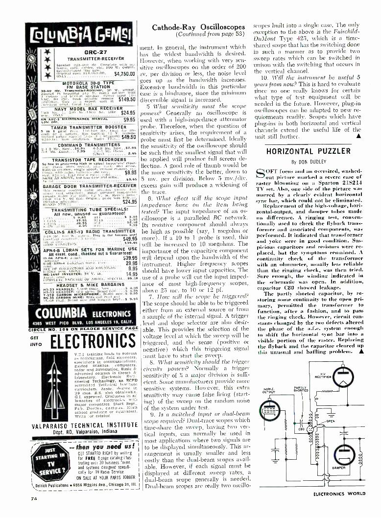
GRC -27 TRANSMITTER -RECEIVER
Special! 223.400 Mc. Complete with an- tenna, rack. cables. etc. 100 W. output. Recanditioned like new. Original cost: $16.000.00. $4,750.00 ONLY
MOTOROLA 30 -D TYPE FM BASE STATION
30 -40 Mc. Transmitter- Receiver. SO W. output. Housed tersa t. da built -in
51§ .peaker,
cabinet input
with 10
VACe GO [eye. Desk console mote $149.50 amplifier. This is superb unit in scellerlt cond. Great buy!
NAVY MODEL RAX RECEIVER 1 -nit Ao. I. 200 Kr. i51I0 Ec. Like $24.95 AN ARC -3 MAINTENANCE MANUAL $9 95 Late edn. f
TAMAR TRANSMITTER BOOSTER 5 to 1 gain! Freq. 118 -1.18 31e. Ideal for air - raft or 2 meters, Has built -in 12 V. transis-
torized power supply! Lists it a [-hopping $49.50 82411.1111. New condition. 2104el TT -5.
COMMAND TRANSMITTERS 2.1.3 51e. New ..36.95 4 -3.3 51e. Iíew $7.95 3 -4 \Ic. Local... 7.95 3.3-7 .11c. (Less
tubes) 2.95
TRANSISTOR TAPE RECORDERS So low In pric[ So high in value! Importers' close - dut! These units record. play hitch. and erase. Built -in speaker, single speed, Volume control. t Comp. with mike. batteries mu] t
e e s $9.95
Iteg. 89ií(315, Like natte Á ec;el, d.... SAME AS ABOVE, but less case and mike.
53.95
GARAGE DOOR TRANSMITTER- RECEIVER 'rhis emote control radio actuates garage door
It toton I not supplied) Small compact transmitter punts un der car dash. 12 V. in. Itres'e power
Input 115 V. 60 cyc. Original price was $íì9.50. Includes hematic. $24.95 IIIS\SD NEVW"!!!
TRANSMITTING TUBE SPECIALS! All new, unused - guaranteed!
671 S 9.95 811 S 3.95 1 -123A . ..... 19.95 811A 595
v -400A .... ... 24.95 SI'3 12.50 .7W 3943 ... 2.95 8:12 4.95
COLLINS ART -13 RADIO TRANSMITTER -IS Mc. 100 2V. output. This is the famous one!
li,ei.I :rm condition. ted,'illd' $49.95 Gum) 1:1 l C11 Id1T111\ $39.95
APN4 -B LORAN SETS FOR MARINE USE All excel. cond., checked out & Guaranteed!
ID66. APN -4i 3 lien $39.95 indicator .. '
R -9B /APN -4 4 channel reeve. 'L_Irei. 29.95 nd.
8ET OF CONNECTORS AND MOUNTING 9.95 MACES FOR ABOVE
14.95 MG -149F INVERTER: 24 V. in. Excel, ul. COMPLETE PACKAGE OF ABOVE. SPECIAL ..89.50
HEADSET & MIKE BARGAINS S 4.95 HS-23 HEADSET: 4..
HS-33 HEADSET: 600 1ohtns.t Brand` n t '....3 5.95 7 -170 CARBON MICROPHONE: Brand new 9.95 RS -38 CARBON MIKE: With coil cord nd PL-68 Plug. Brand new and bargain buy!.,$ 9.95
COLUMBIA ELECTRONICS
4365 WEST PICO BLVD. LOS ANGELES 19, CALIF.
CIRCLE NO. 109 ON READER
ELECTRONICS
SERVICE PAGE
GET
INTO
V.T.I. training leads to success as technicians. field engineers. specialists in communications. guided missiles, computers. radar and automation. Basic &
advanced courses in theory &
laboratory. Electronic Engi- neering Technology, an ECPD accredited Technical Institute curriculum. Assoc. degree in 29 mos. B.S. also obtainable. G.I. approved. Graduates in ail branches of electronics with major companies. Start Sept.. Feb. Dorms, campus. High school graduate or equivalent. Write for catalog.
VALPARAISO TECHNICAL INSTITUTE Dept. RD, Valparaiso, Indiana
Cathode-Ray Oscilloscopes (Continued from page 53)
ment. In general, the instrument which has the widest bandwidth is desired. However, when working with very sen- sitive oscilloscopes on the order of 200 Av. per division or less, the noise level goes up as the bandwidth increases. Excessive bandwidth in this particular case is a hindrance, since the minimum discernible signal is increased.
5 What sensitivity must the scope possess? Generally an oscilloscope is
used with a high- impedance attenuator probe. Therefore, when the question of sensitivity arises, the requirement of a probe must first be determined. Ideally the sensitivity of the oscilloscope should be such that the smallest signal that will be applied will produce full screen de- flection. A good rule of thumb would be the more sensitivity the better, down to 5 mv. per division. Below 5 mv. /div. excess gain will produce a widening of the trace.
6. What effect will the scope input impedance have on the item being tested? The input impedance of an os- cillosctope is a paralleled RC network. Its resistive component should always be high as possible ( say, 1 megohm or more). If a 10 to 1 probe is used, this will be increased to 10 megohms. The importance of the capacitive component will depend upon the bandwidth of the instrument. Higher frequency scopes should have lower input capacities. The use of a probe will cut the input imped- ance of most high- frequency scopes, above 25 mc. to 10 or 12 pf.
7. How will the scope be triggered? The scope should be able to be triggered either from an external source or from a sample of the internal signal. A trigger level and slope selector are also desir- able. This provides the selection of the voltage level at which the sweep will be triggered, and the sense (positive or negative) which this triggering signal must have to start the sweep.
8. What sensitivity should the trigger circuits possess? Normally a trigger sensitivity of ',_ a major division is suffi- cient. Some manufacturers provide more sensitive systems. However, this extra sensitivity may cause false firing (start- ing) of the sweep on the random noise of the system under test.
9. Is a switched input or dual -beam scope required? Dual -trace scopes which time -share the sweep, having two ver- tical inputs, can normally be used in most applications where two signals are to be displayed simultaneously. This ar- rangement is usually smaller and less costly than the dual -beam scopes avail- able. However, if each signal must be displayed at different sweep rates, a
dual -beam scope generally is needed. Dual -beam scopes are really two oscillo-
-- then you need us! GET STARTED RIGHT by writing for FREE 8 page catalog illus-
trating over 30 business forms and systems designed' spec ifi-
- -_ tally for TV -Radio Service.
ON SALE AT YOUR PARTS JOBBER
1 \Oelrich Publications 6556 Higgins Ave., Chicago 31, III.
74
scopes built into a single case. The only exception to the above is the Fairchild- DuMont Type 425, which is a time- shared scope that has the switching done in such a manner as to provide two sweep rates which can be switched in unison with the switching that occurs in the vertical channel.
10. Will the instrument be useful 5 years from now? This is hard to evaluate since no one really knows for certain what type of test equipment will be needed in the future. However, plug -in oscilloscopes can be adapted to new re- quirements readily. Scopes which have plug -ins in both horizontal and vertical channels extend the useful life of the unit still further.
HORIZONTAL PUZZLER By DON DUDLEY
SOFT focus and an oversized, washed - out picture marked a severe case of
raster blooming on a Sparton 215214 TV set. Also, one side of the picture was marred by a clearly evident horizontal sync bar, which could not be eliminated.
Replacement of the high- voltage, hori- zontal- output, and damper tubes made no difference. A ringing test, conven- tionally used to check the flyback trans- former and associated components, was performed. It indicated that transformer and yoke were in good condition. Sus- picious capacitors and resistors were re- placed, but the symptoms remained. A
continuity check of the transformer with an ohmmeter, usually less reliable than the ringing check, was then tried. Sure enough, the winding indicated in the schematic was open. In addition, capacitor C80 showed leakage.
The partly shorted capacitor, by re- storing some continuity to the open pri- mary, permitted the transformer to function, after a fashion, and to pass the ringing check. However, circuit con- stants changed by the two defects altered the phase of the a.f.c. system enough to shift the horizontal sync bar into a visible portion of the raster. Replacing the flyback and the capacitor cleared up this unusual and baffling problem. A
NORM OUTPUT
PARTLY SHORTED
H.V.
RECTIFIER
ELECTRONICS WORLD

Frequency Measurement (Continued frolli pap 47)
is 259.00 cps. Using the same 1000 -cps standard, it is obvious by inspection that the nearest fraction giving a sine -wave pattern is f /4, or 250.00 cps. However, it is also obvious that this choice will give a 9 -cps drift. It is a rare individual svho can count at the rate of 9 per sec- ond. But if we notice that this rapid drift is occurring, we can go back to Step 1, and instead of selecting one cycle, we can pick one -half cycle. Going to Step 2 will reveal that the nearest pattern is 1/8, or 125.00 cps. The drift rate is going to be (259/2) - 125 cps, or 1295 -125.0 =4.5 cps. This rate is easily counted. One merely remembers to convert the final frequency back to the correct range by multiplying by the same factor used to obtain the desired patterns; in this case, a multiplication by two.
If one wishes to use Lissajous figures, the usefulness of a single standard fre- quency is greatly extended. Such pat- terns (ratios) as 5:3, 5:4, 6:5, can provide additional known fractional val- ues of the standard, to overcome the difficulties of rapid drift.
Perhaps an even better way, short of going into more sophisticated and com- plex aggregations of equipment, is to employ an auxiliary audio- frequency oscillator. If this oscillator is known to have excellent short -term .stability, it can be employed with satisfactory results in place of the WWV tones or the accurate tuning fork. The continuously variable feature of the audio oscillator offers the tremendous advantage of furnishing many basic values for the standard fre- quency. Of course it is necessary to synchronize, or compare, the oscillator with a known standard, just before mak- ing a measurement, and proceed directly to make the measurement. Dial readings are valueless and not used except pos- sibly as guides, say, for the 100 -cycle dial increments. The actual oscillator setting, if used as a standard, must in every instance be derived by comparison with a standard, just before use.
August, 1963
T.V. TECHNICIAN
WANTED SOME Know :ix -1
OF EIiGTgOYrtt OfSIRAeLE
NOW receive ALL
channels
All- transistorized SONY Micro -TV and
UHF Adaptor for all- channel reception Now you can tune the full range of television- standard 2 -13 VHF channels and the new world of UHF television. All you need is the Television of the Future, the remarkable 25- transistor SONY Micro -TV, plus the new UHF adaptor that is fully transistorized and has its own built -in antenna. Powered by the Micro -TV, the 13 -oz. adaptor makes use of the new mesa transistor for stepped up sen- sitivity, and accepts an external antenna. Micro -TV, itself a truly portable 8 lbs., operates on its own rechargeable battery pack, auto /boat power, and AC. Micro -TV only $189.95. UHF adaptor com- plete with antenna $49.95. Rechargeable battery, luggage carrying case, other acces- sories extra.
SONY CORPORATION OF AMERICA 580 Fifth Avenue, New York 36, N.Y.
Regional Offices Western: 500 West Florence Avenue. Inglewood. Calif
Central: 4959 W, Belmont Ave.. Chicago 41, III.
O N. V®
Please send me more information on SONY MICRO -TV with UHF
Name
Address
City Zone State
SONY Corp. of Aroer,ca, Dept. EW-S 580 Filth Ave, New York 36. N.Y.
CIRCLE NO. 137 ON READER SERVICE PAGE
SEND ELECTRONICS WORLD
EVERY
MONTH
name
address
city
state
zone
Check one: 3 years for $12 2 years for $9 1 year for $5
In the U.S., and possessions. Payment enclosed fl Bill me
Foreign rates: Canada and Pan American Union countries, add 5OO per year; all other for- eign countries, add $1.00 per year.
New Renewal
Mail to ELECTRONICS WORLD Dept. 1 -8608, 434 S. Wabash Ave.
Chicago 5, III.
75

MICRO ELECTRON TUBE
FABULOUS LOW PRICES!
LARGE SELECT STOCKS!
DEPENDABLE, FAST SERVICE!
Each and every tube is tested In our own laboratory for mutual conduct- ance and life test. We guarantee FREE replacement for one year of any tube purchased from us which fails to function efficiently under any or all operating condi- tions. Prompt refunds are made on any defective merchandise. The advertised tubes are not neces- sarily new, but may be electrically perfect factory seconds or used tubes -each is clearly so marked.
3 042 5X8 61166 65F5 724 10006G 024 513GT 6846 65E7 12AS 1946 1A7GT 5Y40 6865 65.17 12/05 1978 18347 6A7 6867 6567 I2AT6 24A 1640 6Á5 6BL7 GT 65L7GT 12017 25AV5 1145GT 6Á64 6866 659747 12A06 25806 1L4 6AC7 61306GT 6507 12AU7 25066 ILS GAFO 6807 6557 12AV6 25L6GT 1NSCT 6AGS 5BY5G 674 126V7 25W4CT 10501 6/07 6826 678 12/X401 2525 IRS 6AN4GT 6827 ÁU8 t2 /X7 2528 155 6Á66 6C4 616 12AZ7 26 IT4 6AÁ5 GCS 6W4G1 1284 35A5 1U4 GALS 6C6 6W6GT 12BA6 3585 lus 6AL7 6CB6 614 128Á7 35C5 1y2 eAM8 6C0611 6X5 1213E6 351.607 1X2 GANS 6CF6 6X8 120E6 35W4 243 6AOS 6C07 616G 12B67 3514 2AF4 6ÁO6 6CL6 744 /XXL 12806 35250T 3BC5 640701 6086 745 128517 37 3666 EARS 6CM1 746 12817 39/44 38X6 SASS 6CN7 7Á7 12CAS 42 3C136 6Á1S 6058 7Á5 1245 43 3CF6 EATS GCUS 784 1267 45 3C56 6AU40T 60E6 785 12L6 5045 3LF4 GAU SOT 6006 786 1207 SOBS
394 6AU6 6F6 787 125A7 5005 394 SAUR 666 788 12547 501.601 31/4 6AV5GT 644 7C4 12547 50X6 8074 GAYS 645 7C5 12567 56 4627 SAWS 847 7C6 1250701 57 SASS SAX4GT 66601 767 12507 SB SATS 6AX507 667 7E6 12V6OT 71A SAYS 685 665 7E7 12W6GT 75 5AW4 6aA6 6L7 7F7 12X4 76 5867 6805 8NT 7F8 1223 77 5J6 6BCB ÁQ7 767 14A7/1207 78 STS 6806 654 7N7 1486 50 SUSG GOES SUS GOES 6584T 7Q7 1497 54/524 SWAG 68F6 ESA? 7x4 /xxFM IS 11726 SV60T 68464 65C7 774 19ÁÚ44T 117Z6
SEND FOR OUR FREE COMPLETE LIST OF TUBES & SPECIAL PURPOSE TUBES
ALL TUBES SENT POSTAGE PAID. Please send 358 handling for orders under S5. Send 25% deposit on
.0.D. orders. Send approximate postage on Canad- ran and foreign orders.
MICRO ELECTRON TUBE CO.
P.O. Box 55 Park Station, Paterson 3, N. J.
CIRCLE NO. 127 ON READER SERVICE PAGE
ENGINEERING ' B.S. DEGREE
SCIENCE II IN 36 MOS.
MATH -.ad likkalliW
}' 2 , A 0,ti ' k I ;1 Ñ 11,Ìi
U.S. NEEDS 50,000 NEW ENGINEERS A YEAR! EARN ACCREDITED B.S. DEGREE in Sc epee or Engineer- ing in 36 months- yearround program optional. 27. month engineering diploma also available. Classes start September, January, March, June. QUALITY EDUCATION. Graduates employed throughout the U.S. and foreign coun- tries. Government approved for veteran training. Students from 50 state.. 40 untries. 20 buildings; dorms, gym. Campus. New library and laboratories. Employment help provided.
SAVE DIME AND MONEY. Write for catalog
and Information. 1608 E. Washington Blvd., Fort Wayne 2, Indiana
Eff 76
Indiana Institute of Technology formerly Indiana rechnica/ College
Calibrating Test Equipment (Continued from page 45)
to 0.1 microvolt is available. An instru- ment of this type is also useful in labora- tory applications other than calibration.
A less complex resistance voltage di- vider is shown in Fig. 4. Designated model RD -1 by its manufacturer, North Hills Electronics, it is available for $425. Used in conjunction with an ex- ternal voltage source, its output is that fraction of the input which is indicated by the numerals above each of the dec- ade switches.
For precise resistance calibration, Thomas -type standard resistors (named after the person who developed them) are available from Leeds cr Northrup. The one shown to the left in Fig. 5 is
a 1 -ohm unit certified to an accuracy of 0.0001% if temperature is controlled. Shown with it are other standard re- sistors with values of i ohm and less.
While d.c. standards and calibration methods have traditionally lent them- selves to greater accuracy than is ob- tainable for a.c., recent developments have improved a.c. techniques consider- ably. Since there is no a.c. equivalent of the standard cell, most sources of a.c. voltage and current are refined, elec- tronic signal generators. One company, for example, offers an a.c. standard at 400 cps that is accurate to ± 0.1% in frequency and = 0.025% in voltage.
Aside from voltage, one dealing with a.c. may want to check such other param- eters as impedance and power factor. Precise units of inductance and capaci- tance are called for. Figs. 6 and 7 show devices in this category made by Leeds
Northrup. Fig. 6 is a capacitor box made up of precisely calibrated, highly stable mica capacitors mounted on high - quality decade switches. Its rated ac- curacy is ±0.1 %, +0.5 pf. Calibrating capacitors more precise than this set, although they will seldom be required, are available.
The Brooks "Inductometer" of Fig. 7, available for $550, consists of three sets of carefully wound coils. One set is
mounted in the rotating disc, which is
calibrated in millihenrys. One set of fixed coils is located above the disc, another below it. When the disc is ro- tated, mutual- inductance changes pro- vide the variety of inductance readings possible. The coils have been carefully designed and shaped so that rotation over 170 degrees produces an almost linear change. At 1000 cps, the "Induc- tometer" is accurate to ± 0.3 %.
Conclusion
The relatively crude procedures out- lined for the simple v.o.m. and v.t.v.m. in the early portion of this article can be improved considerably and also
made easier with some of the devices described subsequently. Also, with these more refined standards, other types of instruments and parameters can be checked. Yet, of necessity, the special devices available have only been touched on. The complex matter of frequency calibration and standards, for example, has not been treated at all. Actually it would take more than one volume to give the broad area of calibration and standards comprehensive treatment.
Nevertheless, much has been achieved if interest in the subject has been aroused. On the practical level, further information can be obtained from the National Bureau of Standards and the manufacturers mentioned in this article on the following: standards, their prices, and organizations that specialize in pro- viding calibration service.
Another practical alternative is avail- able for individuals or small organiza- tions that prefer to do their own work but cannot justify the required invest- ment. If calibration checking is not done on a steady schedule, it is possible to rent precisely calibrated equipment on a short -term basis, either for a particular job that requires exceptional accuracy or to check regular equipment. General Electric's Instrumentation Service in Schenectady, N.Y., for example, offers a long list of rental equipment. While the manufacturer's own line is, of course, fully represented, instruments from other sources are included on the list. A Wheatstone bridge by Leeds & North- rup, to cite one example, is available for $18 a month. G -E also maintains, as do other manufacturers, an instru- ment repair and calibration service shop from which trained technicians are avail- able on an outside -call basis.
Any firm interested in maintaining precision of its measuring instruments has a wide choice of alternatives that may be fitted in with its needs and its budgetary considerations.
o m o o 0
ELECTRONICS WORLD

SIMPLE
HUM- BUCKING
CIRCUIT By G. R. GILBERT
THE simple addition of a hum-buck- ing circuit to any high -gain amplifier
is well worth considering. In almost all cases, residual 1111111 will be reduced to virtual inaudibility and in every case substantial reduction will result.
Hum troubles usually occur when the preamplifier is connected, particularly if the compensation circuits have to cope with a pickup head with very small out - put. The simple circuit shown in Fig. 1
operates by feeding hum in opposite phase from the heater of the first pre- amplifier tube into the suppressor of the same tube. As there is a phase reversal between the control grid and the sup- pressor grid, hunt voltage feci to the sup- pressor bucks the control -grid hum.
R1 is a wirewound pot of from 100 to 500 ohms with a preferred value of about 200 ohms. The potentiometer is wired as close to the 171 tube socket as is con- venient with the variable arm going to the suppressor. The usual pair of 100 - ohm fixed resistors, R2 and R3, are con- nected as shown, forming a center - tapped ground for the remaining tube heaters.
When wiring this circuit into an exist- ing amplifier, or even when wiring a new amplifier, Vl's suppressor should not be connected to the cathode, as is usually the practice.
The adjustment is simple. Turn the volume control up so that the residual hum is clearly audible, then rotate R1 until the hum either vanishes or is at a minimum. A well -defined null usually occurs.
This circuit is far more effective as a hum -reducer than the more commonly used -humdinger,- which consists of a low -value pot connected across the heater supply with the moving arm going to ground.
The circuit can be applied to as many tubes as required, as adjustment is made to each stage independently.
Fig. 1. Circuit used to feed hum to the suppressor grid in order to buck it out.
Aucust, 1963
m
z m
CG'
SPHERICAL
SOUND
IS
COMING!
GENERATOR
NEW
SIZE: 11" x 8" x 4 -1 4
f I. FREQUENCY RANGE (WITH- OUT BOOM) 8 :VATTS (MEASURED)
FOR LITERATURE AND DEALER INFORMATION / /RITE
o/l,Ï non r - Qf son Corporalic,i 2424 E. 55th STREET, DEPT. 3A, INDIANAPOLIS 20, INDIANA
NEW CIRCLE NO. 128 ON READER SERVICE PAGE
NEVER FAIL - ZONE
YOUR MAIL
The Post Office has divided 106
cities into postal delivery zones
to speed mail delivery. Be sure
to include zone number when
writing to these cities; be sure
to include your zone number in
your return address -after the
city, before the state.
FLORIDA ELECTRONIC TECHNICAL INSTITUTE
IN THE HEART OF MISSILELAND TRAINS MEN FOR SUCCESSFUL CAREERS IN ELEC- TRONICS WITH IMPORTANT COMPANIES AT THE WORLD'S BEST KNOWN MILITARY INSTALLATION, CAPE CANAVERAL.
APPROVED VETERANS TRAINING PROGRAMS Take Advantage of This Opportunity NOW
FLORIDA ELECTRONIC TECHNICAL INSTITUTE, INC. 105 King Street Cocoa, Florida
NEW! LAFAYETTE 12- TRANSISTOR 2 -WAX.
11A.KIE T: IC WITH SQUELCH
only 39.95 2 for 78.88 More fun ... better per.. formance . greater value. than ever. Superb for fishing, hunting or business use. No age re- strictions or license re- quirements when used as per Part 15 FCC regula- tions. Features: separate microphone and speaker for better sending and re- ceiving, excellent noise squelch; crystal controlled receive and transmit. posi- tive action push -to -talk switch and 46" telescop- ing antenna. As a bonus feature, the HE -100 may be operated in the home with an AC power pack. (Optional see below) Saves batteries too! Includes crystals, earphone, leather carrying case and batter-
ies. Shpg. wt.. 22 oz. Imported HE -tool Walkie- Talkie Net 39.95
Pair for 78.88 NEW! AC POWER PACK
Converts 117VAC to 9V DC. Plugs into HE -100. HE -97 Net 7.45
rLAFAYETTE Radio ELECTRONICS Dept. RH -3, P.O. Box 10, Syosset, L.I., N.Y. Send me: Walkie Talkie
AC Power Pack Shipping charges collect. $
mo , II
(HE -100L) fl
(HE -97), I enclosed.
Name
Address
City Zone State
CIRCLE NO. 124 ON READER SERVICE PAGE 77

TEST EQUIPMENT PRODUCT REPORT
For RCA Model WR -51A FM Stereo Signal Generator
copy/ of manufacturer's brochure circle No. 58 on coupon (page 19).
A VERY specialized signal generator is required for servicing and main-
tenance of FM stereo adapters, tuners, and receivers. The new RCA WR -51A is
such a generator; it produces all the sig- nals needed for proper adjustment of stereo circuits. This unit must be used in conjunction with a scope to observe response and output waveforms of the equipment being adjusted.
The generator produces a composite stereo output signal with either left -only or right -only modulation. A special left - plus -right signal is also available for ac- curate phase adjustment of subcarrier transformers. Various audio frequencies (400 cps, 1 kc., and 5 kc.) are utilized for modulation. A 19 -kc. crystal -con- trolled subcarrier signal is provided for
1/2 12AT7 19-KC. XTAL OSC.
1/2 6AU8A 19 -KC.
BUFFER
1/2 12AT7 19 -KC.
DOUBLER
checking the lock -in range of stereo re- ceivers. Sine -wave outputs at 28 kc., 38 kc., and 67 kc. are generated for band - pass and SCA filter network adjustment.
Built into this unit is a 100 -mc. r.f. oscillator that may be frequency modu- lated with the above signals. This per- mits the stereo information to be applied to the front ends of FM tuners and re- ceivers for over -all r.f. -i.f. alignment checks. In the event that there is an FM station right at 100 mc., it is possible to shift this frequency slightly by means of a front -panel control.
Another crystal oscillator in the gen- erator (at 5.35 mc.) is used to produce a 10.7 -mc. i.f. marker for the tuner's i.f. response curve. In addition, harmonics of this oscillator may be picked up at 90.95 mc., 96.30 mc., 101.65 mc., and 107 mc. for a check of a tner's r.f. and oscillator alignment.
The instrument also includes a zero - center meter that measures 1.4 v. r.m.s. either side of zero. This meter is used to check the electrical balance of a stereo amplifier audio output. Two cables at the rear of the instrument are connected to the voice -coil output terminals of the amplifier. With a mono or an L +R sig- nal applied to the amplifier, there should be equal outputs from both channels and the meter will read in the exact center.
1/2 6AU8A 38 -KC.
AMP.
6CG7 a 1/2 I2AU7A
AUDIO OSC. a CATHODE
FOLLOWER
19 -KG. PHASE - SHIFT
NETWORK
78
38 -KC. BAL. MOD.
(2) INI92'S
H. LOW -PASS
DELAY LINE
1/2 6CG7 COMP. /AUDIO
AMP.
1/2 I2AU7A 19 KC. AMP.
BALANCE METER
1/2 6CG7 XTAL I.F. MARKER
GEN.
RIGHT INPUT
LEFT INPUT
I.F. MARKER
COMPOSITE SIG. /AUDIO
C
6AN8A 100-MC. -o-
OSC. a MOD.
R.F. ATTEN.
R.F. OUT.
o
With a left -only signal, the meter will deflect to the left; with a right -only sig- nal, it will deflect to the right.
A block diagram of the instrument is included. Considering all the functions provided, the unit is remarkably simple. It uses only 6 dual -purpose tubes, 4 crystal diodes for the balanced 38 -kc. modulator and meter rectifiers, 2 crys- tals for frequency control, and a silicon rectifier.
Accompanying the WR -51A is an ex- cellent manual-: This not only goes into complete details on the operation and use of the generator, but also includes a fine section on maintenance and adjust- ment of the unit itself. Some of our test - equipment manufacturers would do well to study this manual to see how it should be done.
The generator is fairly portable, weighing 14 pounds and measuring 13',_ "x 10 "x 8 ". The price of the unit is
$ 249.50.
Associated Research 2850 Megohmmeter
For copy of manufacturer's brochure, circle No. 59 on coupon (page 19).
ANEW' test instrument designed for field and bench testing of insulation
on electrical components and equipment has been introduced by Associated Re- search, Inc. as the "Vibrotest" Model 2850. This is a megohmmeter that is able to measure resistances as great as ten million megohms at 500 volts d.c., or one million megohms at 50 volts d.c. Accu- racy of ±2 percent is achieved over most of the range at 500 volts, and ± 5 per- cent over most of the range at 50 volts.
The meter can be used to measure resistance between conductors on a
printed circuit, as well as insulation re- sistance of transistors, miniaturized parts: cables, and motors. It also meas- ures leakage resistance of capacitors and can be used for measuring grounded and ungrounded sections of three -terminal resistors.
Many megohmmeters use a hand - cranked generator or batteries to pro-
ELECTRONICS WORLD

duce the test voltages. In this instru- ment, a.c. line power is rectified by sili- con diodes to produce the d.e. required. To prevent line -voltage variations from affecting the readings obtained, a cath- ode- follower voltage- regulator circuit is used (see block diagram) .
A fused three -wire a.c. line cord grounds the case for shock protection. The instrument is protected from over- load damage, even in cases of direct shorting, by an electronic overload cir- cuit. The metering circuit uses miniature
INPUT 117V.A.C. DIRECT -
CURRENT
POWER
SUPPLY
OVERLOAD PROTECTOR
vacuum tubes, and the meter itself is a 200 -µamp. unit.
Guard circuits are employed to con- trol stray and leakage currents to assure accuracy at maximum sensitivity. A ter- minal for external guard use is provided, and a selective- return grounding circuit offers maximum guarding flexibility when the instrument is utilized to test production components or permanently installed equipment.
The instrument weighs about 10 pounds and is available for $250.
RETURN
ELECTRONIC REGULATOR
FOR 50V. & 500v.
SELECTIVE - RETURN
GROUNDING
GUARD
METER
O ELECTRONIC METERING - CIRCUIT
AMPLIFIER
RANGE SELECTOR TEST
AND DISCHARGE CIRCUITS
Sencore CR125 Cathode -Ray Tube Tester For copy of manufacturer's brochure, circle No. 60 on coupon (page 19).
THE most expensive component in a TV set is the picture tube. Fortun-
ately, modern picture tubes are quite ruggedly built and they ordinarily last a long time. Although the tube's heater does burn out or open up completely, it is far more common for the tube to operate month after month but at re- duced emission (and consequently, a darkened picture). Another common de- fect is the depositing of cathode or other foreign material between the tube's elec- trodes, resulting in inter -element leak- age. This has many effects, ranging from lack of brightness control, poor contrast, dark picture, bright picture, and others, NOVE
.. 041 I. . .a ,.,. . .
SI-A
depending on the location of the leak- age and the circuitry.
The new Sencore CR125 not only is a complete tester for picture tubes, but it also is frequently able to remove inter - element shorts, restore emission by re- juvenation, and weld together open cathodes. The instrument can check tubes ranging from an 8- incher all the way up to the 30 -inch tube, and this includes color -TV picture tubes as well. The tests performed include those for inter -element shorts, cathode emission, and a check on the operation of the control grid. For these tests, d.c. is used on all tube elements (except for the
R2 10 N
D R 13
I
100
1I] VA
<R
_.
August, 1963
..z rtn 53
heater) and emission of over 300 pa. is indicated as "good" on the meter scale. New tubes normally measure 900 -1500 pa., but since the high end of the 500 -µa. meter is suppressed by a crystal diode, the meter does not go off scale. The grid bias can be adjusted from 0 to -100 v., and the effect can be noted directly on the emission meter.
Suppose the tube you are testing shows leakage or a short between con- trol grid and cathode. The tester can then be used to remove this short. It does this by applying momentarily to these electrodes a high voltage (450 v.) from a large electrolytic capacitor (C5 -B in the diagram). The length of time that this voltage is applied depends on the amount of leakage; with high leakage (low resistance) a large current flows for perhaps 1/6 second or so; with low leakage, less current flows for a second or more. If the material causing the leak- age is burned away during this process, you may see a momentary flash in the neck of the tube. This procedure can be tried several times until the short is burned out.
If the tube being tested shows low emission, then the CR125 is set up for rejuvenation. During this procedure, we attempt to bring new active emitting material to the surface of the cathode and to enlarge the aperture in the con- trol grid. There are three steps available for the rejuvenation procedure. In the first step, a high voltage is momentarily applied to the control grid. If this does not do the job, then the second step is tried. Here, the heater voltage is raised slightly while the high voltage is ap- plied. If the tube still does not respond, then the third step is tried. The heater voltage is raised still more and the length of time that the high voltage is applied is lengthened.
When color -TV picture tubes are tested or rejuvenated, each of the three guns is checked and connected to the tester separately, as determined by the position of the "Color Gun" switch.
Like all Sencore's instruments for the service technician, the cathode -ray tube tester is designed for convenience and portability. It is available at the com- pany's distributors for $69.95.
79

Tarzian offers
FAST, DEPENDABLE
TUNER REPAIR
SERVICE !INES
ONLY
95 INCLUDING
ALL PARTS (except tubes)
and LABOR
24 -HOUR SERVICE
1 YEAR WARRANTY
Sarkes Tarzian, Inc. maintains two complete, well -equipped Factory Service Centers -assisted by Engineering personnel -and staffed by spe- cialized technicians who handle ONLY tuner repairs on ALL makes and models. Tarzian -made tuners received one day will be repaired and shipped out the next. Allow a little more time for other tuners.
One year guarantee against defective workman- ship and parts failure due to normal usage. Cost -$9.50 per unit. $15 for UV combinations. Ab- solutely no additional, hidden charge for ANY parts, except tubes. You pay shipping costs. Re- placements on tuners beyond practical repair are available at low cost.
When inquiring about repair service, always give TV make, chassis and Model number. Tuners repaired on approved, open accounts. Check with your local distributor for Sarkes Tarzian replace- ment tuners, replacement parts, or repair service. See your distributor, or use the address nearest you for fast factory repair service:
\JSARKES TARZIAN, I NC,
537 South Walnut Street
Bloomington, Indiana
Tel: 332 -6055
10654 Magnolia Blvd.,
North Hollywood, Calif.
Tel: 769 -2720
CIRCLE NO. 134 ON READER SERVICE PAGE
BC -221 FREQUENCY METER with original Calibration Book and Crystal. Lab. C 69.50 checked out. xlnt.
c ondition
MAGNESYN COMPASS, complete remote reading s> -tem, for plane or boat. 12 V -DC input. ?Clot condition. With schematic
AN /APN -9 LORAN RECEIVER -INDICATOR Completely lab. aligned and checked Out. With 24 Volt DC Inverter, mount 124.50 and plug- xlnt.
c ondition
BC -455 COMMAND RECEIVER. 6-9 MC xlnt. condition
24.95
8.95 BC -458 COMMAND TRANSMITTER. 5.3 to 9.95 7 MC. Brand new all above items subject to prior sale. Don't Wait!
Send Money Order or Cheek with Order Write for Latest Flyer -LOADS OF BARGAINS!
R W ELECTRONICS 2430 S. Michigan Avenue Dept. 873 Chicago 16, Illinois Phone: CAlumet S -1281
80
Signal- Generating Equipment (Continued from page 34)
Crystal -controlled calibrators provide a 100 times improvement at frequencies corresponding to harmonics of the cali- brator. This accuracy does not hold at other frequencies, though, simply be- cause the tuning dials of the instruments cannot be read with that kind of pre- cision.
However, frequency can be moni- tored with an electronic counter to a far higher degree of accuracy. With the aid of a precision transfer oscillator and heterodyning techniques, counters can determine frequencies as high as 18,000 mc. /sec. (and higher) to an accuracy of 8 decimal places.
If an oscillator can be voltage con- trolled, phase -locking techniques can be used to maintain the output frequency at the same stability as a reference crys- tal oscillator. This can be done, though, only at spot frequencies corresponding to harmonics of the crystal oscillator fre- quency.
Precisely known signal frequencies are available from frequency synthe- sizers, which obtain various r.f. fre- quencies by dividing, multiplying, add- ing, and subtracting other frequencies derived from crystal -controlled oscilla- tors. The newest signal source of this type generates frequencies all the way from 0.01 cps to 50 mc. in ,0.01-cps steps by push -button control. All of these 5 billion discrete frequencies are derived from one highly precise 1 -mc. crystal oscillator and all are accurate to better than 0.0000003%! This is three ten -mil- lionths of one percent.
The accuracy of signal- generator out- put amplitude indications can't ap- proach accuracies such as those available for frequency -primarily because highly precise standards of r.f. power never existed until only recently. High -quality generators have had output accuracies in the neighborhoòd of 1 to 2 db. Now that more accurate r.f, power monitors are becoming available, the trend is to- wards the use of power leveling for signal- generator output amplitude con- trol. In these systems, the power monitor maintains constant output power by means of a wide -band, direct -coupled feedback loop which controls an ampli- fier control grid, or one of the new elec- trically controlled p -i -n diode modulator/ attenuator units. Output power flatness can be held to within 0.2 db with this technique. The accuracy of the power monitoring system is typically ± 0.5 db over -all, however an additional ± 1 db should be added because of attenuator accuracy throughout the frequency range of the equipment.
Little effort has been expended on controlling the accuracy of pulse gen- erators with respect to pulse width and
amplitude; the major design effort being directed towards achieving good pulse shape. Pulse generator calibrations are used for no more than a rough initial indication of pulse amplitude, width, or repetition rate. Because pulse generators are most often used with an oscilloscope, the pulse generator controls are usually adjusted exactly while monitoring on the oscilloscope.
Choosing Equipment The first thing to do is to take a good,
hard look at what the equipment is in- tended to do. What frequency ranges are needed and which can be omitted? What kind of signals are desired -sine wave, pulsed, FM, AM, or what?
What stability does the generator have? That is to say, if you set it at one frequency how confident can you feel that the generator will stay exactly at that frequency? What is the amplitude stability? If you set the output for 1 volt r.m.s., will it stay at the exact 1 -volt set- ting all afternoon, or if you change fre- quency?
A design engineer is very much con- cerned with these matters. When de- signing an i.f. strip, for instance, he needs a generator with an output that is flat across the band, so that the detected response will show him where the i.f. strip isn't flat. The serviceman repairing the same strip can get by with a genera- tor of lesser quality. About all that he can do is to set the traps to the right frequencies, get about the right slope to the band edges, and take excessive tilt off the passband. A few humps in the generator output won't affect these ad- justments significantly.
Check the performance of the attenu- ators, which are needed to prevent over- driving high -gain equipment. Is the attenuator accurate, and is its attenua- tion constant with frequency? And watch out for r.f. leakage. A big attenua- tion factor doesn't tell you anything if r.f. power leaks into the tested circuit anyway.
How much harmonic content is pres- ent if you are supposed to be getting pure sine -wave output? If there are har- monics, you may think that a filter cir- cuit is passing a certain frequency when it is really passing a harmonic. With r.f. generators, the standing wave of a har- monic may be much higher than the fundamental, providing a false indica- tion.
Certainly, the reputation of a manu- facturer is of considerable importance. Reputable manufacturers check the per- formance of many production units and then set specifications beyond the widest deviations. Sometimes their specifica- tions may not appear spectacular, but with this kind of equipment perform- ance will always be better than claimed.
ELECTRONICS WORLD

RADIO
TV NEWS
SPEAKING at a meeting of NATESA in. Kansas City, Frank W. Mansfield,
Director of Market Research for Sylvania Electric Products, said that their three - month national survey of color -TV set dealers and owners showed that at least 20 brands of color sets are available on dealer floors. About 70% of dealers indi- cated that their customers had little or no trouble with color repairs and set owners generally were not critical of tun- ing problems previously associated with color sets. The Sylvania survey also indi- cated that the average repair bill on a color set amounted to about $30.50 per year or less than 90 a day. About 40% of the set owners said that the cost of color repairs were no more than they had experienced with black -and -white sets. An additional 22% were so uncon- cerned that they could not recall what their repair bills were in the previous 12 months.
Mansfield also pointed out growth of American households from the present 55 million to an estimated 77 million in 1977 will he a factor in increasing color sales. At least 90% of these households can receive colorcasts on their black -and- white sets and about 45% have annual in- comes in excess of $6000 which means that they can be considered prime pros- pects for color -TV receiver sales. This also means quite an upswing in sales of antennas, transmission lines, and test equipment for use by service technicians.
Soviet TV Expands The 130th TV station in the Soviet
Union has been opened in Krasnovodsk, a town on the Caspian Sea. The first broadcast coincided with the 25th anni- versary of Soviet TV, which started March 9, 1938. Since then, the number of TV sets in the Soviet Union has climbed to over 8,000,000 serving a pop- ulation of about 100,000,000. In addi- tion to 1:30 TV stations, a large number of relay stations cover remote rural areas. Moscow TV programs are carried by 63 stations on a network that covers most of the country.
Color programs are already being car- ried in both Moscow and Leningrad, but according to Soviet authorities, further development is hampered by the high August, 1963
price of color sets. Like their American counterparts, Soviet engineers are cur- rently engaged in a cost- cutting program. At present, color -TV sets are being used only in hotels, rest homes, clubs, and "Palaces of Culture."
Space -Far and Near Those who followed Gordon Cooper's
space flight on TN' would be interested to know that at the lift off, a TV camera coupled to a telescope located about 20 miles from the launch site was used to supply TV networks with pictures of the launch.
Heart of the system is the BX -7 image orthicon developed by Bendix. Tests of the TV- telescope show it capable of spot- ting a basketball at 100 miles and resolv- ing objects less than one -half mile long on the moon.
Electronics and Mud A Cornell University research team is
currently seeking the solution to a prob- lem that has plagued humans since the first man got bogged down in the mud. The group is trying to develop a tech- nique to electrically reduce the water content of soil then combine it with cer- tain chemicals to stabilize the soil so it can bear a heavy load. Past experiments have shown that water in the soil at- taches itself to positively charged par- ticles and these particles, together with the water, would be attracted to a nega- tive charge. The group is testing the fea- sibility of using a metal grid about 15 to 20 feet wide and as long as practicable over the muddy area. Buried beneath the grid would be a pipe or series of pipes. The grid would serve as one pole, either positive or negative, and the submerged pipe as the other pole. Conceivably, with a negatively charged grid and positively charged pipes, the water would move to the surface under the grid and be carried away in drainage ditches. At the same time, soil -stabilization chemicals are in- troduced through the submerged series of pipes.
The work is currently being conducted in the laboratory and if it works OK, it will then be field tested.
Give this some thought next time you get bogged down in the family wagon.
TRANSISTOR IGNITION
READY -TO- INSTALL CONVERSIONS
YOU can get TOP MILEAGE, HIGHEST PERFORM- ANCE, LONGER POINT & PLUG LIFE, BETTER WIN- TER STARTING, and MANY OTHER ADVANTAGES with one of our INEXPENSIVE TRANSFIRE systems. These include HERMETICALLY -SEALED AMPLIFIER, HIGH -RATIO COIL, BALLASTS, Leads & hardware.
MODEL T 6 or 12v. neg. grd. $39.95 MODEL T2 TWO TRANSISTORS,
250:1 coil $44.95 MODEL TP 6 or 12v. pos. grd. direct
installation wo. insulating points $54.95 MODEL TS Special, 40kv system $59.95 MODEL TS2 TWO TRANSISTORS,
400:1 coil $49.95 TWO- TRANSISTOR KITS Everything needed to build conversion. Includes transistors, coil, ballasts, heat sink, decal, etc.
KT2 with TX250 coil for 30kv output . $34.95 KTS2 with T400 coil for 40kv output . $39.95
KT1 one transistor with 400:1 coil . $27.95 6 or 12v. Negative -ground only. Point insulation kit adapts to positive ground, $2.50 pp. 1 oz. Epoxy potting plastic in mixing bag $1.95 pp.
HIGH -RATIO IGNITION COILS with free circuit dia- gram.
TX250 Heavy duty coil 250:1 ratio $ 9.95 T400 HIGH EFFICIENCY 400:1 coil for
HIGHER OUTPUT and Or LOWER TRANSISTOR VOLTAGE $11.95
FULL LINE of PARTS at NET PRICES. Free lists. Dealer opportunities. Marine models available. When ordering, specify voltage and car. Add postage for 4 lbs. on kits and cone's; 3 lbs. on coils. $5.00 deposit with COD's.
PALMER ELECTRONICS LABORATORIES Inc. CARLISLE 1, MASS. 617 -AL 6.2626
CIRCLE NO. 144 ON READER SERVICE PAGE
Wiizeya! YAGI COUPLERS
The new
low -cost way to
tailor -make your
own special
antenna system
using a single
down -lead! NO ROTOR NEEDED!
No interaction. No loss. Couple 2 or more cut -channel yagis to each other, or couple cut -channel yagi(s) with any other VHF broadband or all- channel antenna. Elimi- nates "mixing networks ", rotors, switches. Convenient, automatic. Write for Fact- - Finder #231.
WINEGARD COMPANY 3003 -8 Kirkwood Ave., Burlington, Iowa
CIRCLE NO. 140 ON READER SERVICE PAGE 81

D SCOTT'
NEW MULTIPLEX VERSION OF FAMOUS
SCOTT 310"TELSTAR" FM TUNER
Scott's 310 tuner has long been admired for exceptional sensitivity and selec-
tivity. It is used as a broadcast monitor by FM stations throughout America and
was selected by Bell Laboratories for receiving signals from Telstar orbiting in
outer space. The new 310E includes exclusive Scott Time -Switching mult Flex
circuitry, silver -plated front -end, Auto -Sensor for fully automatic reception, pre-
cis on meter and many other exclusive features. Sensitivity is 1.9 ,.v! $219.95*
r- ' H. H. Scott, Inc. Dept. 160 -08
111 Powdermill Road, Maynard, Mass.
Rush me complete technical details on new 310 -E FM Stereo Tuner.
Name
Address
City
I
I
1
L
Zone State
`Slightly higher West of Rockies. Accessory Case Extra. Export: Morhan Export.ng Corp., 458 Broadway, N.Y.C. Canada: Atlas Radio Cora., 50 Wingold Ave., Toronto.
CIRCLE NO. 135 ON READER SERVICE PAGE
THE INDUSTRY'S ONLY COMPLETE
"LOOK -ALIKE" LINE Exact Replacement Needles/Cartridges
Keep controls and switches
use QUIETROLE The original products of its kind.
An Industry
Used by every segment of the in- dustry. Those who know, know the difference that makes it the best. Imitations are only poor substtutes.
Highest quality guaranteed/ At your
E -V distributor's or write ,or FREE rep.'acement guide, today! Electro- Voice, Inc.,
Bu_hanan, Michigan. Dept. 837N
fray'ec. CIRCLE NO. 112 ON READER SERVICE PAGE
82
Supplied in 2 -4 -8 oz. bottles and 6 oz. Spray - Pack with extender.
manufactured by
QUIETROLE COMPANY
Spartanburg, South Carolina
In Canada: CROSS CANADA ELECTRONICS
12 Laurel Street, Waterloo, Ontar o
CIRCLE NO. 131 ON READER SERVICE PAGE
Naval Time Signals (Continued front page 30)
the signal is a series of rhythmic c.w. signals or "beeps," beginning 5 minutes before the hour and providing the list- ener with five separate time checks - one at the 56th minute; one at the 57th; one at the 58th; one at the 59th; and one on the hour. Due to mechanical or operator variance, the signal may not necessarily begin at the 55th minute, however, this is of no consequence, since the beginning is not to be used as a marker. As the signal proceeds through the 55th minute, the halfway point is indicated by the omission of the 29th second. As the "beeps" continue, you will also note a blank at the 51st second, followed by signals on the 52nd, 53rd, 54th, and 55th seconds. These four "beeps" following the 51st second is a code reference alerting the listener of the approaching 56th minute time sig- nal. The 55th second c.w. signal is fol- lowed by a 4- second silent period, which is ended by the time signal, precisely indicating the 56th minute. This is the end of the first time check.
The 1- second "beeps" continue through the 56th minute as indicated in Fig. 1, with the 29th second blank as in the preceding minute; again denoting the halfway point. As the signal ap- proaches the end of the 56th minute, the 52nd second is omitted (instead of the 51st second as in the preceding check), followed by the 53rd -, 54th -, and 55th - second markers, and then by the 4 -sec- ond silent period. The silent period is
ended by the time signal, precisely indi- cating the 57th minute. During this sec- ond time check, the three 1- second sig- nals at the 53rd -, 54th -, and 55th -second markers serve as the code reference for the 57th- minute check.
This procedure is repeated for the 58th- and 59th -minute time checks with the 53rd and 54th seconds omitted re- spectively. A long dash, preceded by the 9- second silent period, composed of the omission of the 51st through the 59th second "beep," denotes the hour. The beginning of the long dash indicates the on time."
To summarize, the listener need not laboriously count the "beeps" through- out the entire time signal, but only to note the number of second markers pre- ceding each of the 4- second silent peri- ods. If four 1- second indications are heard, he is alerted to the 56th- minute time check. If the listener hears three "beeps" preceding the 4- second blank period, he will know that the 57th min- ute is coming up, etc. And when he hears the 9- second silent period, he will be ready to set his watch or chronom- eter to the exact hour.
The time signals transmitted from
ELECTRONICS WORLD

NSS Washington, D.C. are regulated to an accuracy of 0.01 second. This pre- cision is obtained by observation of the stars, using special telescopes and tran- sits. Accuracy is further enhanced by enclosing the equipment in environ- mental chambers, which maintain the delicate instruments at a constant tem- perature and humidity, thereby minimiz- ing metal distortion. The signals from NBA, NPG, NPM, and NPN are re- broadcast from Washington by automat- ic relay and are correct to 0.25 second.
Thus we have precise time signals being transmitted by radio at frequent intervals throughout the day on frequen- cies ranging from 114 kc. in the 1.f. range to 2:3,650 kc. in h.f. range.
ODD A.G.C. FAULT
By DON DUDLEY
THE COMPLAINT, a snowy picture, was not an unusual one. The trouble
persisted on this Sylvania 21C407 after replacement of the r.f., i.f., and keyed a.g.e. tubes. Tuner a.g.c. voltage was found to be high, but there was no in- dication of any a.g.c. voltage on the i.f. grids. At this point, it was noticed that a 100k resistor in the a.g.c. line, 1143, was burned out. It accounted for the absence of a.g.c. on the i.f. tubes, but it did seem odd that a resistor with so little voltage across it could burn up.
After H43 was replaced, the set seemed repaired. A finger placed on that resistor was pulled away quickly, how- ever- because R43 was quite hot. A quick voltmeter check showed no more than a normal a.g.c. d.c. voltage present. C50, which couples the keying pulse from the horizontal- output system, was checked and found to have a small
t of leakage. It measured 20 meg- ohms resistance. However, it could not pas, d.c. into the a.g.c. line, because the kc, ing pulse was derived from a sepa- rate, isolated, a.g.e. winding on the fly- back transformer. Nevertheless, when (:50 was replaced, R43 no longer over - heated. The defective capacitor evidently coupled a keying pulse of too great an amplitude into the a.g.c. system. The resistor was being burned out, not by d.c., but by a.c. A
TO I.F. GRIDS TO HORIZ. TRANSFORMER
C331 r
LEAKY
R43 IOOK
R18
R.F. 47K R41 GRID 470K
R42 3.9MEG..
255V.
2I5 V.
August, 1963
C50 22000.
IKV.
A.G.C. KEYING
Ís
a qua 4 the BIG NEWS in ' TEST INSTRUMENT KITS
... and hallicrafters engineered quality means outstanding specifications and performance . . . plus simplified construction!
NEW "Fail- Proof" soldering terminal strips simplify mak- ing of positive connections.
CAPACITANCE DECADE Kit HD -1 Ideal for experimental and service work requiring pre- cision capacitors. Sixteen -- commercial slide switches give total variability in 100 pf steps. Uses silve. mica capacitors and long lasting stable defilm capacitors. Range .0001 to 1.0 mfd in four decades. Price $14.95
NEW assembly ease. Mechan- ical parts are riveted to the chassis at the factory.
CONDENSER TESTER Kit HC -1 Handy service bench instrument for checking unknown condenser and re- sistor values under operating condi- tions. Has precision tuning eye for easy operation. Four capacitance ranges: 10 mmf to 2,000 mfd. Three resistance ranges: 0.5 ohm to 5 megohms. Price $29.95
5 -INCH OSCILLOSCOPE Kit HO-1 A ca o pf
Has scope
full for
5 Mservic. bandwidthing color
,
Tube is 5 UPI. One -volt peak -to -peak source attenuator permits voltage
rrr r measurements over range of 10,000 r r;. 1 to 1. Retrace blanking amplifier pro - .v vlded. Phasing is continuously vari-
able from 0 to 140 °. Has two axis (beam) modulation. Price $84.95 L----,.
RESISTOR DECADE Kit HD -2 Use to substitute known - value precision resistors in a circuit, Resistors are one -watt, 10 %. Twenty -
eight commercial slide switches give total vari- ability in 1 -ohm steps. Range: 1 ohm to 10 ohms in seven decades. Price $14.95
R.F. GENERATOR Kit HG-1 Generates frequencies from 50 kc. to 55 Mc. in six steps. Calibrated harmonics in two steps from 55 Mc. to 220 Mc. Low frequency range exceptionally stable. Accu- racy P/2% of the reading. R.F. output .1 -volt. Bandswitch as- sembly pre -wired and calibrated. Price $29.95
VACUUM TUBE VOLT MILLIAMETER Kit HM -1 Has an exclusive built -in milli - ameter circuit, available at the turn of a switch. Illuminated meter and separate front panel On -Off switch. Has seven AC, DC voltage ranges, from 1.5 to 1500; seven ohmeter ranges, 0 to 1,000 meg- ohms; and six milliameter ranges, 1.5 to 500. Price $29.95
BATTERY ELIMINATOR Kit HP -1 I Reliable source of 6- or 12 -volt DC power for servic-
e ing car radios, including transistor and "hybrid." AC ripple less than .25 %; exceptionally low. Voltage ranges 0 -8 volts and 0 -16 volts. Also use as battery
_ charger. Has voltage and current panel meters. Price $49.95
(7
Look for . at your Authorized
this display¡ HaHeadq Headquarters!
1
bali/creí/erg For FREE Catalog, write Dept. 14 -H, 5th & Kostner Aves., Chicago 24, III.
CIRCLE NO. 141 ON READER SERVICE PAGE
IT'S A "SNAP" to love big money on all of your high fidelity component require- ments. Simply mail us your list for a special quote.
Write for discount catalog A -17, full of snappy audio bargains.
KEY ELECTRONICS CO. 120 Liberty St., New York 6, N.Y.
Convert any television to sensitive.
BIG -SCREEN OSCILLOSCOPE with m i n o r . expensive changes. Ingenious circuit. No electronic experience needed to follow our clearly. illustrated plans. TECH- NICIANS. HAMS. EXPERIMENT- ERS. BROADCASTERS. Use in shop. school. lab. Any set -any size
FULL PLANS $2. RELCO, Dept. EW -7, Box 10563, Houston 18, Tex.
engineering degree in 27 mos. Bico;i :m Electronics Engineer. College graduates enjoy higher income . . . advancement. ]Ltjor corporation, visit us regularly to interview and employ seniors. B.áCIIELOR OF SCIENCE DEGREE IN 27 MONTHS in Electrical (Electronics or Power major), Aeronautical, Chemical, Mechanical, Civil Engineering. IN 36 MONTHS a B.S. Degree in Business Administration. One -year Drafting -Design Certificate Program. Small classes. Well - equipped labs. Campus. Dorms, new library. Moderate Costs. Enter Sept., Jan., Mar., June. Founded 1884. Write
n1 I. H. McCarthy for Catalog and "Your Ca-
- reer in Engineering and Commerce" Book.
1 683 College Avenue Angola, Ind.
83

f 5?_ FREE Catalog . , . OF THE WORLD'S FINEST j GOV'T. SURPLUS `fl, ELECTRONIC BARGAINS
SUMMER SPECIALS: f
SHURE MICROPHONE 1/2 PRICE a
TEN FOUR MODEL CR4M
150-250 Ohms 50 DB Controlled Reluctance Microphone with high impact "ARMO -DUR" case, as de- signed for the Armed Services. Response 200 -8000 CPS., Semi - Directional. Ideal for mobile use. Complete with coiled cord, four u prong plug, push to talk SW, and hanger. Shpg. Wt.: 2 lbs. Regu- lar Net Price: $19.20
OUR PRICE: $960
TRANSFORMERS: 6.6 VOLTS -HIGH AMPS
ALL PRIMARIES: 115 V / 120 V I 125 VI 132 V -60 Cycle:
SEC.: 6.6 volts 35 Amp. Size: $s 95 5x4x6 ", Wt.: 24 lbs..... Price: ,
SEC.: 6.6 Volts 25 Amp. Size: 41/2x6x4 ". Wt.: 17 lbs.... Price: $4.95
SEC.: 6.6 Volts 18 Amp. Size: 41/2x51 /4x4 ". Wt.: 12 lbs... Price: $3.95
SEC.: 6.6 Volts 10 Amp. Size: 4x31/4x4 ". Wt.: 9 lbs..... Price: $2.95
PARABOLIC ANTENNA & MICROWAVE REFLECTORS -As previously advertised are still available. Write and tell us your needs. Ask for our CATALOG!
Address Dept. EW Prices F.O.B., Lima. O. 25% Deposit on C.O.D.'s Minimum Order $5.00
SEND FOR BIG FREE CATALOG!
FAIR RADIO SALES 2133 ELIDA RD Box 1105 LIMA, OHIO CIRCLE NO. 115 ON READER SERVICE PAGE
ADVANCE ELECTRONICS SILICON CONTROLLED
PRV 7AMP 25 AMP 200 2.50 3.75 300 3.35 4.35
Other Sizes Available
RECTIFIERS TESTED!
PRV 7AMP 25 AMP 400 4.25 4.95 500 5.10 5.60
on Request
NPN- Germanium Mesa Transistors F max -250 Mc- BV -10V ... 10 /$5. 100/$39.
VARIACS 1 amp $5.50 -13/4 amp 56.25 -3 amp $8.95
10 amp $18.95 -20 amp $24.95
PANEL METERS 0 -150 VAC 2" $3.95 -0 -250 DCV 4" Sq. $5.95 -0 -1 MA.DC 1/ " Sq. 53.95 -0 -1 DC.MA 2" ARB. SCALE 53.95 -0 -150 DC.MA 3" $3.95- 0-25 DC.MA 4" Sq. $5.95
RG -8 /U CABLE- RG -8 /U CABLE - $7.75/C FT. $70.00 /M FT. - CONNECTORS -
PL-259 - 6/52.70 50 -239 - 6/$2.49
All Shipments FOB NYC
ADVANCE ELECTRONICS 79 Cortlondt St., New York 7, N.Y. RE 2 -0270
Converts home or car radios to re- ceive Fire, Police, Aircraft, CB, SW, etc. Excellent sensitivity on High & Low Bands. High Band type ad- justs to bracket 150 -160 MC. Low Band type should be ordered for 33 -47 MC, 40 -52 MC. 26 -30 MC, 9 -12 MC, etc. Adaptable for tran- sistorized car radios.
315 -B 115 -1600 MC $17895
Order today or send for free catalog on full line of converters and receivers for every application.
KUHN ELECTRONICS CINCINNATI 17, OHIO
SAVE HI -FI COMPONENTS
TAPE RECORDERS MONE1 SLEEP LEARN KITS
MERITAPE ` °w cost, high guolity recording
tope, n boxes or cans. , FREE 1963 CATALOG
DRESSNER 1523 JERICHO TPKE. NEW HYDE PARK i6 N.Y.
Operational Amplifier (Continued from page 49)
Fig. 2C adds hysteresis to the transfer unction. Now the input must exceed
a value determined by the output volt - 1ge, Rl, and R2 to cause the amplifier to
S to its negative limit, and then must become less than some more nega- tive new value to cause the amplifier to S into its positive limit.
Fig. 2D is one type of free- running multivibrator using the above principles. The circuit starts out in one of its lim- rts, but the voltage at C, being charged through R, eventually becomes great enough to cause the amplifier to switch to its other limit. Then C is charged through R in the opposite direction and the amplifier eventually switches back to the first condition described above and so on.
Waveform Generators
Fig. 4A is a highly refined circuit that simultaneously generates square waves and triangular waves with per- fectly straight ramps of equal positive and negative slopes. The output of an integrator with a d.c. input, Eia, is a
perfectly linear ramp whose slope in volts -per -second equals - Eia /RC. In Fig. 4A, when the positive -going voltage out of amplifier No. 1 reaches some value determined by the setting of Rl- R2, amplifier No. 2 will switch to its positive limit. This output is clipped to plus 1 volt by diode action. This voltage is re- applied to the integrator, amplifier No. 1, and causes its output to decrease linearly to a new value. This causes am- plifier No. 2 to switch to its negative limit. This, in turn, causes the integrator to produce a positive -going ramp, and so on.
The slope of the integrator in volts - per- second with the ± 1 volt clipping action of the diodes is 1 /RC. The ampli- tude and frequency of the triangular wave output are both affected by the setting of R1 -R2. This circuit has been used successfully from 1 cycle- per -min- ute to 1000 cycles -per- second. Typi- cally, RI/ R2 will be from 4:1 to 20:1.
By putting a diode in parallel with R,
the waveform is changed from a tri- angle to a saw -tooth with the fast rise or fast fall determined by the polarity of the diode. Connecting a diode directly from the output of the integrator to
ground, as shown, makes the device monostable, and it can be triggered by capacitively coupling a negative voltage spike into the secondary input of ampli- fier No. 2. This arrangement then makes a device capable of providing a per- fectly linear slow triggered sweep for inexpensive oscilloscopes. The high -level square wave is then used to provide retrace blanking for the scope. Obvi- ously, the above waveforms must be
84
direct -coupled to the oscilloscope verti- cal -input terminals.
Timing Computer In the foregoing section it was men-
tioned that the output of an integrator with a d.c. input is a perfectly linear ramp voltage whose slope in volts -per- second equals - Eia /RC. Because of this an integrator can be used as a tim- ing device, with output voltage being proportional to time. Such an applica- tion is shown in Fig. 4B. In operation S1 is opened first. The output voltage, as measured on the meter, then increases from zero at a perfectly linear rate in respect to time. When S2 is opened, the output voltage will hold its last value. Then time, the interval between the opening of Si and S2, equals (E..t x RC) /150.
It is necessary to carefully zero -adjust the amplifier immediately prior to use. To do this, open S2 first and then Si. The meter reading should remain at zero volts. If it drifts off, reset the zero - adjust control to cause it not to drift off. C must be a low -leakage unit, prefer- ably polystyrene, silver mica, or Mylar. Otherwise the d.c. leakage will cause errors and drift.
This circuit was used to measure the muzzle velocity of a Grossman carbon - dioxide pellet pistol. Si and S2 were actually two strips of aluminum foil ;R
inch \vide and 2 inches long mounted on cardboard frames with cellophane tape. They were placed exactly one foot apart. The gun was then placed a few inches from Si, aimed to first break Si and then S2, and fired. The anticipated time interval was about 3 msec. R was chosen as 100,000 ohms and C as .15 µf.
After the gun was fired, the meter indi- cated 22 volts. Time was then calculated to be 2.2 msec. and velocity to be 1/.0022 or 455 feet -per- second.
Some of the circuits in this article were taken from material supplied by George A. Philbrick Researches Inc., Boston, Massachusetts.
oG "'po o m e,c0
r.
"That's what IT says! In MY opinion.... "
ELECTRONICS WORLD

NEW PRODUCTS & LITERATURE
Additional information on the items covered in this section is available from the manufacturers. Each item is identified by a code number. To obtain further details, simply fill in the coupon appearing on page 19.
COMPONENTS TOOLS TEST EQUIPMENT HI -FI AUDIO CB HAM COMMUNICATIONS
PORTABLE HUMIDITY METER 1 Laucks Laboratories. Inc. is now llering a
portable lnunidity ureter which protides in- stantaneous direct reading of relative humidity from 20% to 95 %. Featuring all solid -.state cir- cuitry. the unit incorporates a precision meter
with damped d'Atsonval movement and full - range accuracy within ±5f,. An electrolyte -type transducer is mounted on a 5 -foot cord.
The metal cabinet is 10" x 6" x 7" and has a transistor -type self -contained power source. 'l'he rotary switch has "off," "on," and "calibrate" positions, 7'he linear pot adjusts for voltage reg- ulation.
V.O.M. FOR SEMICONDUCTORS
2 The Triplett Electrical Instrument Co. is now offering a v.o.m. specifically designed for
semiconductor testing. The Model 630 -L offers two special low -power ohms circuits on the XI and X10 ranges. These ranges have beets designed for safe testing of semiconductor circuits. The maximum open- circuit test voltage is only 0.140 volt. This allows testing belote the breakdown voltage of the transistor or other semiconductor without damaging overloads. Maximum power dissipation its the semiconductor under test is less than 420 microwatts.
Housed in a molded case with transparent un- breakable Lucite window, the instrument meas- ures 311/22 "x 1'1t "x 71/2" and contes complete with leather carrying handle. Weight is 5 pounds.
TRANSISTORIZED CCTV CAMERA . North American Philips Company, Inc. is
now offering an ulna- compact. self -con- tained, completely transistorized CCTV camera for surveillance of inaccessible or remote arcas. The unit will adjust itself automatically to chang- ing light intensities on the order of 1:15 and will produce a bright clear picture with light levels as low as I footcandlc.
The camera measures 13 "x 7 "x 1" and weighs
August, 1963
II pounds. It can he mounted almost anywhere as it generates virtually no heat. It is completely ruggedized and will withstand shock and vibra- tion. It is tropic -proof, resistant to extreme hu- midity, and will operate in temperatures ranging from 14 to 113 degrees F, indoor or outdoors. \ \'ith a weatherproof accessory cover, it can be used in any weather.
The camera is capable of feeding up to 30 standard TV receivers or a lesser number of video monitors without any accessories or amplification.
METERED -KNOB VARIABLE TRANSFORMER
4 The Superior Electric Company is note offer- ing sixty of its "Powerstat" variable trans-
formers with knobs incorporating a direct -read- ing voltmeter as standard equipment. Single ttnirs with enclosed construction. with and without cord -plugs, are available for 120- and 240 -volt single -phase service with loads up to 3 kva. Con- version kits consisting of a metered knob. en- closure, and complete wiring instructions are available for converting currently catalogued n pew.
The voltmeter is insensitive to stray magnetic fields. The meter reads load voltage, but line voltage can be checked by matching marks on knob and enclosure.
U.H.F. CONVERTER SStandard Kolisman Industries, Inc. is now of- fering a deluxe u.h.f.- to- v.h.f. TV converter
which features a two- speed, ball -bearing plan- etary drive permitting single -knob fine tuning of the picture.
Designed for screwdriver installation, the cir- cuit uses a 6DZ4 tttbe and nuvistor for longer life
and improved reliability. Sliding contacts 1E/NC
been eliminated in the main tuning circuit through use of a three -gang tuning element. A power receptacle is built into the back of the chas- sis to plug in the TV power cord. The set carries UL approval.
Frequency range is channels 14 through 83, with good performance on translator channels 70 through 83. The device is housed in a high -style cabinet measuring 117/4 "x 53/4 "x 3 ".
TEMPERATURE RECORDER e F. L. Moseley Co. has introduced a new, com- e} pact strip -chart recorder for tracing tempera - tures in research, testing, and industrial work.
The " Autograf" Model 682 is a servo potenti- ometer type instrument designed for rack mount- ing singly or in pairs. or for bench -top operation. It measures 61" x 73 /a" x 8W'.
The input circuit features a plug -in unit in- corporating a single cold junction compensated temperature range selected by the customer. The reference junction temperature is factory adjusted to any specified value. Accuracy. exclusive of thermocouple errors, is better than 0.2% of full
scale.
the ,turd is produced by pen and ink from a cartItige type reservoir or by stylus on pressure. sensitive paper.
INDOOR U.H.F. ANTENNAS 7 Channel Master Corp. has recently intro- / duce(' two new u.h.f indoor antennas, the "Wonder Bow" and the "Double Wonder Bow."
The "Wonder Bow," Model 4170, is a single - bay bow and screen with a wire form dipole; while the Model 4160 is a stacked bow and screen. also using wire forni dipoles. Rear pickup is eliminated because both antennas arc reflector- designed and directional.
Both antennas are finished in a gold color and styled for use in the home.
DYNAMIC ALTERNATOR TESTER 8 Mar -Con Instrument Corporation is now
marketing a dynamic alternator tester. the "Mark I" DAT -100.
The instrument, de- signed for use by the average auto service- man, will test for short- ed or open alternator field windings and slip - ring assembly, test for shorted or open alter- nator diodes, and test for shorted or open al- ternator stator wind- ings. Controls are kept to a minimum. A meter marked with "good" and "bad" zones is used as the indicator. The in- strument is powered by the 117 -volt. 60 -cps power line and consumes 7 watts. Accessories include a three -wire test lead cable six feet long and a 4" jumper. A .6 -amp "Slo -Blo" fuse is built into the line. The instrument measures 10" x 6" x 31/2".
DIGITAL MILLIVOLTMETER sHouston Instrument Corporation has devel- oped a digital millivoltmeter which measures
d.c. voltages from 1µv. to 1000 volts in six over- lapping ranges. Known as the "Auto Data" Model 2660, the unit has 3 -µv. accuracy with 100-
85

megohm input impedance on the lowest 00.000 to 29.999 millivolt range, making the instrument suitable for thermocouple, strain gage. low -level transducer, and small -signal semiconductor meas- u remen ts.
Gold- contact, hermetically sealed reed relays are used in a decimal potentiometric bridge. Reed relays are switched under zero current con- ditions for long life. Accuracy is independent of changes in reed contact resistance. Floating input allows for operation at up to 500 volts above ground. Common mode rejection is greater than 100 db at 60 cps.
10
SEMICONDUCTOR TESTER Fairchild Semiconductor is now offering a
new 'go /no -go" multiparameter tester, the Series 250. Capable of conducting tests at the rate of 900 units per hour, the new instrument features 16 various "go /no -go" tests per unit.
The tester features pulse testing and can be operated by non -technical personnel after only a
few hours of training. The Series 250 is easily programmed with decade cards or fixed resistor cards. Accuracy at I pa. is ±0.5% ( ±1% at 100
pa.). A system for priority sorting is optional.
11
TRANSISTOR IGNITION SYSTEM Autottonics Inc. is now marketing a low -cost transistorized ignition system which is being
offered in four different models to meet the re-
quirements of various 6- and 12 -volt automotive s{ stems.
The ignition system consists of two major com- ponents: a coil manufactured by Bosch of Ger- many and a dual transistor control unit. The electronic control unit which is mounted on a flat bracket is installed directly below the ignition coil. The electronic assembly is hermetically sealed and completely embedded in semi -rigid epoxy.
The kit includes the coil, transistor control unit. wire. necessary hardware, and complete in- stallation instructions.
12
INSTRUMENT PANEL KIT Electro -Kits is now offering a completely self - contained panel -production kit for the proto-
type electronics lab or the serious experimenter. The kit produces up to four color -permanent
aluminum panels in 20 minutes. No graphic skills are required and no darkroom or other special equipment are necessary. Since no dangerous chemicals are involved in the process, the com- plete operation can be performed on a table or lab bench.
PULSE ENERGY COMPARATOR Electronics for Education, Inc. is now offer- ing the Model 152 pulse energy comparator
which provides a quantitative indication of the missing r.f. pulses conning from a magnetron. When used with a conventional external counter,
86
it provides for stability tests in accordance with military specifications.
The instrument contains provision for measur- ing: the number of pulses having an energy con- tent less than a preselected percentage of the energy content of the preceding pulses; or the number of pulses having an energy content less than a preselected percentage of a "standard" pulse.
U.H.F. PREAMP /CONVERTER
1
A Jerrold Electronics Corporation is now mar- 14 keting the "Ultra- Vista," a u.h.f. converter that includes a built -in stage of u.h.f. preamplifi- cation.
A top -of -the -set converter, the unit features slide -rule tuning, a 6D1.4 /EC88 frame -grid tube as the c.f. preamp. a KID silicon diode as the
mixer, an AI530(1 nuvistor as the oscillator, and a
PADT -28 high -frequency transistor operating as
the post or i.f. amplifier. Gain is at least 10 db over the translator bands
(channels 70 to 83) and a minimum of 11 db over the \IPATI stations (channels 72 to 76). The unit conforms to FCC rules for radiation. Input im-
pedance is 300 ohms with a v.s.w.r. of 1.5 maxi- mum. Output impedance is 300 ohms.
SOLID -STATE PULSER
15 Digital Electronics, Inc. has developed a
solid -state pulser, the Model 522, which can be used to provide fast -rise pulses from input waveforms of any type. The unit can also act as a
frequency divider or a pulse shaper. With no in- put signal a single pulse can be generated by pushing the button on the front panel.
The output pulse width may be divided from less than 0.5 µsec. to greater than 0.1 second. Rise time is less than 50 nsec. for a negative pulse and
200 nsec. for a positive pulse. Fall times are the same. Amplitude of the output may be varied from 0 to 15 volts and is 5 volts into a load of 100
ohms.
HI -FI - AUDIO PRODUCTS
STEREO TAPE RECORDER
1
e Roberts Electronics, Inc. has announced the U availability of the Model 1057 -PS stereo tape
recorder with photo- sound -sync to provide sound - with -slide synchronization for amateur and pro- fessional photographers.
The fully automatic synchronizer which adapts to all automatic slide projectors utilizes a strip of special sensing tape on the shiny side of the recording tape to activate a "sensing" post. This automatically advances each slide in the projector.
The unit offers stereo and mono record /play; three speeds, 3.75, 7.5 ips with 15 ips available extra: sound- with -sound; sound -on- sound; sound - over- sound; four stereo outputs: 24 -slot wave wound motor; full stereo record /playback system; stereo preamp outputs: stereo power amplifier
outputs; dual professional -type vu meters; stereo self -contained speakers; vertical or horizontal operation; automatic tape shut -off; and facilities for FM /stereo multiplex.
LOUDSPEAKER IN KIT FORM 17 Electro- Voice, Inc. is now marketing a pre - 11 finished loudspeaker kit that can be put to- gelher in less than 20 minutes without tools. Designated the "Coronet," the system combines an 8" extended -range loudspeaker with a ducted - port acoustic phase- inverter enclosure.
Three versions of the unit are available: "Coro- net I" includes the enclosure kit and an 8" \IC8 "Michigan" speaker; the "Coronet II" with en- closure kit and "Wolverine" LS8 speaker: and the "Coronet III" which includes the enclosure materials and an SP8B, the company's deluxe 8" speaker. All systems feature exterior surfaces of select hardwood veneers, pre -finished in oiled walnut.
MONO /STEREO TAPE PREAMP
1
Allied Radio Corporation has recently in-
U trottuced the "Knight" KN -4002, a stereo tape record /playback preamp of flexible per- formance its either mono or stereo sound record- ing and reproduction.
Response is 30- 16.000 cps ± 3 db at 7.5 ips and 50- 12,000 cps ± 3 db at 3.75 ips. Hunt and noise is -50 db minimum on playback. Twin visual indicators and concentric dual playback
and record controls for each channel permit ad- justment simultaneously or independently. A red "record" safety light shows when the preamp is
set for the recording functions, while the indi- cator beacons permit peaking at correct levels on each channel for perfect tapes.
The unit measures -114" x 151/2" x 81/a "..t grey metal case is available as an accessory.
TAPE -DUPLICATING SYSTEM 113 Ampex Corporation has recently introduced IJ a tape duplicating system, the PD -10, which is designed to provide professional tape duplica- tion facilities for schools. With the system, a sin- gle operator can produce up to 75 copies of 1200 -foot tapes in an 8 -hour day. The duplicating operation requires no technical training.
The standard system consists of one master and three slaves which will produce up to three dupli- cates at a time. Master and duplicate tapes can he half -track, two -track mono or two -track stereo. Master tapes may be any of the popular speeds from 17 /s to 15 ips. producing copies at 17/s. 3.75, 7.5, or 15 ips. Copies may be decreased in speed from the master by one standard speed.
STEREO TUNER -AMPLIFIER
20 Radio Corporation of America has recently introduced a high_ fidelity F \( multiplex
stereo /AM tuner-amplifier which incorporates a
nuvistor F\I front end. Designated the MX -7, the unit includes FM
multiplex. a high -fidelity F \I tuner, AM tuner, and a "Master Control" 30 -watt stereo amplifier. Special features include a new multiplex demodu- lation system. special high-fidelity tubes and
ELECTRONICS WORLD

circuits, nuvistor r.f. amplifier tuner, and under- rated components for trouble -free operation.
The control unit features touch lever controls, multiplex indicator lights, dual volume controls, optional remote unit, dual bass and treble con- trols, a.f.c., phono input provision for mono or stereo phono connections, and impedance match - ing for 4 -, 8- and 16 -ohm speakers.
STEREO POWER AMPLIFIER
21 Dynaco, Inc. has added the "Stereo 33" to its "Dynakit" line of audio equipment in kit
form. This new stereo power amplifier delivers wide -
band, low -distortion output of 171/2 watts per channel. The full 35 watts is available continu- ously over the 20 to 20,000 cps spectrum. The
design features both positive and negative feed- back plus specially engineered transformers. The amplifier is designed to be used with the com- pany's PAS -2 or other high -quality stereo pre - amps. It matches the PAS -2 in appearance and size.
22
PORTABLE SOUND ANALYZER B Sc K Instruments, file. has developed a port- able noise analyzer for general industrial ap-
plications involving noise control and as a basic instrument in acoustical or vibration -measuring systems.
The Model 2203/1513 consists of the Model 2203 sound level meter and an octave -filter set. Accuracy is ±1 db from 20 to 15.000 cps over the full -scale range of 22 to 134 db. The unit pro- vides accurate readings for eleven frequencies from 22 to 25,000 cps with center frequencies as specified by ASA S1.6 -1960.
The unit weighs 11V2 pounds and is housed in a cast- aluminum case. A leather carrying and holding handle and removable leather shoulder strap make the unit portable.
23
STEREO RECORDER KIT Heath Company is now marketing a portable, four -track stereo tape recorder in kit form as
the Model AI) -72. The kit contes complete with all amplifiers an(
speakers. The unit records and plays four -track
stereo and mono tapes, 7.5 and 3.75 ips speeds. has microphone and in -line inputs, concentric level and tone controls, bar -type level indicators, and dual two -way speaker systems.
The unit is housed in a factory assembled port- able case with lift top lid and swing -out detach- able speaker wings. A free head- alignment tape is included with the kit.
24
STEREO TUNER /AMPLIFIER H. H. Scott, Inc. has recently introduced its Model 340B FM stereo tuner- amplifier. The
new model features new panel styling, slide -rule tuning, convenient front -panel earphone recepta- cle, and "Auto- Sensor" circuitry which automat-
August, 1963
RFOR "DOCTORS OF
SERVICING" 1
SILICONE B ASE
C S, LU
Por, AnG pR07: -; rs
Where there's a contact... or a re /ay.,. Service with Contact Shield! Pro- tective! Corrective! It not only cleans and safeguards contacts bet- ter on TV, radio, and hi -fi sets; on all relay- operated electrical equip- ment, regular protective mainte- nance with this versatile cleaner prevents sticky relays -while cor- rective servicing unsticks them... in seconds. Promotes greater con- ductivity, keeps relays working smoother, longer. Contact Shield - the professional service man's cleaner.
APPLICATIONS
INCLUDE:
Bowling Alley Automatic Pin Spotters
Vending Machines Pinball Machines
Slot Machines Telephone Switchboards
IBM Computers and other data
processing equipment
Industrial Equipment using relays, such as
welding machines, etc.
For handy guidebook to better servicing, write Channel Master Corp., Ellenville, N.Y.
CIRCLE NO. 108 ON READER SERVICE PAGE
PLATE TRANSFORMERS AMERTRAN- Primary 105 -125 AC. 60 Cy. Secondary 3100 -0 -3100 V. AC (n 600 MA $75.00 (2 KVA) Price ea. J Primary 110V. 60 Cy. Secondary $9.95 1125 -0 -1125 m 250 MA ea.
FILAMENT TRANSFORMERS All 110 VOLTS -60 CYCLES unless noted
Sec. 6.3 V. 4 A.1.75 I Sec. 6.3 V. 25 A. 4.75 Sec. 6.3 V. 5 A .1.95 Sec. 12.6 V. 5 A S 2.95 Sec. 5 V 52 Amps 116 KV ins) 517.95 210 Pri. 60 Cy. Sec. 1.6 V 1100 amp. $18.95
RELAYS 6 VOLT DC 3PST -N.O .65 12 VOLT DC DPDT 1.35 110 V. AC SPOT Plug -In 1.50 Sens. 11,000 Ohm Coil 1 Ma. Adj. SPOT 1.95
PIV 100 200 400 750 200 400 100 200
SILICON RECTIFIERS Current 500 Ma 500 Ma 500 Md 500 Ma 750 Ma 750 Ma 2 AMPS 2 Amps
Price $ as
.30
.50
.90
.30
.50
.35
.55
Ply 400 100 200 400
50 100 200
Current 2 Amps
15 Amps 15 Amps 15 Amps 50 Amps 50 Amps 50 Amps
Price $1.00
1.50 2.75 3.75 3.50 4.25 5.00
BRAND NEW O L CONDENSERS 50 MFD 200 VDC 4.50 2 MFD 2000 VDC 1.50
2 MFD 600 VDC .50 4 MFD 2000 V1)C 3.50 3 MFD 000 vue .60 6 MFD 2500 VDC 5.50 4 MFD 00(1 VDC .75 2 MFD 4(1(1(I VDC 6.25 5 MFD 60() VDC .80 3 MFD 41)00 VDC 8.95 6 MFD 600 VDC .85 4 MFD .11)00 " 12.95 8 MFD O(10 VDC 95 1 MFD 5000 VDC 4.50
30 MFD 000 VDC 1.19 2 MFD 511110 VDC 8.50 12 MFD 00() VDC 1.50 4 MFD 6000 VDC 15.95
1 MFD 1000 VDC .50 .5 MFD 7500 VDC 2.95 2 MFD 1000 VDC .70 1 MFD 7500 VDC 6.95 4 MFD 10()0 VDC 1.35 2 MFD 7500 " 17.95 8 MFD 1000 VD(' 1.95 2 MFD 1(1.000 " 29.95
10 MR) 1000 VDC 2.50 2 MFD 12,500 ° 34.50 12 MFD 1000 VDC 2.95 1 MFD 15.000 ° 42.50
1 MFD 1200 VDC .45 2 MFD 18,000 " 69.50 1 MFD 1500 VDC .75 1 MFD 20,000. 59.50 2 MFD 1500 VD(' 1.10 .5 MFD 25,000 ^ 34.95 4 MFD 1500 VD(' 1.95 I MFD 25,000 ^ 69.95 8 MFD 1500 VDC 2.95 10 MFD 300 AC. 1.95 1 MFD 2000 VD(' .85 3 MFD 1000 VAC 1.95
SPECIALS LOW IMPEDANCE DYNAMIC MICROPHONE ELEMCNT .. ,.990 MINIATURE EARPHONE - MagnetuC - with Cord, plug and jack - American made 650 BC 442AM ANTENNA BOX 1 95 21/2" Meter 100 -0 -100 Microamps 2.95 0 -365 MMF VARIABLE CONDENSER 1/a" Shaft 756 21,2" 0 -100 MICROAMP METER 3 95 4" Rect. 100 -0 -100 Microamps 4 95
PEAK ELECTRONICS CO. 66 W. Broadway, New York 7, N. Y., WO -2 -2370
CIRCLE NO. 130 ON READER SERVICE PAGE
/ 0 CUT "OIL
GREENLEE CHASSIS PUNCHES Make accurate, finished holes in 11/2 minutes or less in metal, hard rubber and plastics. No tedious sawing or filing -a few turns of the wrench does the job. All standard sizes . . .
round, square, key, or "D" shapes for sockets, switches, meters, etc. At your electronic parts dealer. Literature on request.
GREENLEE TOOL CO. GREQ/VLEE
2027 Columbia Ave., Rockford, Illinois CIRCLE NO. 120 ON READER SERVICE PAGE
87

ically switches to stereo or mono mode of opera- tion depending on which type of broadcast is being received.
An illuminated d'Arsonval meter permits pin- point tuning of all signals. There is a powered third channel for direct connection of remote speakers or for a three- channel system. Complete tape monitoring facilities are also provided. All controls operate on playback.
SOLID -STATE P.A. AMPLIFIER
25 Royce Electronic Developments. Inc. is now offering the "Audio Robot" line of min -
turized solid -state p.a. amplifiers including -watt models to operate from self -contained bat-
teries. vehicle batteries, or a.c. power lines. Three - speed phonograph facilities are available on any model.
Accessories available for use with the . ampli-
100 TUBES OR MORE
30C PER TUBE
OTT s With ever Order
fiers !nc udc siren tone generator and automatic switch -over to batteries in the event of power failure.
26
INDUSTRIAL TAPE TRANSPORT Viking of Minneapolis, Inc. is now offering the Model 230, a heavy-duty reel -to -reel tape
transport designed for industrial and commercial applications. The unit will handle reels up to and including 7 and quarter -inch tapes of all types. Single tape speeds of 15. 7.5, 3.75, or 17/8 ips are available as is a two -speed model for 15 and 7.5, or 7.5 and 3.75 and Ws ips.
The transport is available with a aide choice
of head configurations, alternative choices of capstan drive motors, and with or without such features as digital counter or photoelectric or mechanical type run -out switches.
21
STEREO TAPE RECORDER Inter -Mark Corporation is now offering a
new stereo tape recorder which includes a
heavy -duty detachable speaker system as its "Ci- pher VII."
The unit features three- speed operation, two vu level meters, individual controls on each chan- nel for volume and tone, instant stop lever which also operates when the machine is in the record mode. fast forward and rescind. digital counter.
TUBES 1111. G U i I AN'1E 1; ) )
Mutual Conductance Lab-tested. Individually Bored. Branded and Code Dated
OZ4 6AU4 1B3 6AU5 1H5 SAU6 114 6AV6 1T4 6AW8 1U4 6AX4 1X2 6BA6 2A5 5BC5 3Ca6 6BD6 5U4 6BG6 5V4 5BH6 5Y3 6816 5Z3 6BL7 6A6 6BN4 6A8 SBN6 6AB4 .56Q6 6AC7 5BZ6 6AG5 6C4 6AL5 5CB6 6A48 SC D6 6AQ5 6C F6 6AS5 6CG7 6AT6 6CG8 6AT8 6CM7
6CZ5 65117 766 606 6517 7B7 6DA4 6SK7 768 6DE6 65L7 6DQ6 65N7 7Y4 6EM5 6507 12A06 6F6 6SR7 1ZAE6
If uni shipped it, 24 firs
YOUR ORDER FREE! 6H6 6U7 12AF6 6J5 6U8 12AT7 6J6 6V6 12AU7 6K7 6W4 12AX7 6L6 6W6 12B4,6 6Q7 6X4 12806 6S4 6X5 12BE6 6SA7 7A7 12BF6 6SC7 7A8 12BH7
12BL6 12BY7 12C5 12CA5 12DQ6 125147 12SQ7 25L6 25Z6 35W4 35Z3 35Z5 50A5 50L6 24 27 41 45 47 75 77 78 80 84/6Z4
Other tubes and CRT's at low prices_ send for free list
LIVE IN THE EAST? WAITED MONTHS FOR DELIVERY FROM OTHERS?
AIR MAIL AN ORDER TO COP.NELL
AID RECEIVE DELIVERY TO THE EAST COAST
IN AS LITTLE AS 72 HOURS!!!
NO SUBSTITUTIONS WITHOUT YOUR PERMISS 0
per tube
(No Limit) from this list
6A65 6SN7
6AU6 616 6Y6
6CG7 6K3 6W4 .rl1J!!
Tubes ale new, seconds or used and so marked.
TERMS: FREE POSTAGE ON PREPAID USA ORDERS. Under $5.00 add 50c for handling. Send 25% iepostt on C)D orders. No Canadian or foreign COD's -incl Ale postage. No 24 Hr. Free Offer on personal checl. orders. 5 -DAY
MONEY BACK OFFER!
CORNELL ELECTRONICS CO. Dept 4217 niversit Ave. San Diego 5. Calif. Phone: AT 1 9792 EW8 L F Y K
CIRCLE NO. 142 OPi READER SERVICE PAGE 88
11ItimommIP titi;'IiÏlÉll iiül!;¡íd
t I -
autonratic talc :.rut -oil sound- ou- tu-.uul :.ecm l-
ing, and stereo earphone connection. Jacks a
also provided for radio, phono, and microphone. Frequency response is 35- 15,000 cps at 7.5 ips
and signal -to -noise ratio is said to be better than 50 db. The unit can be operated in either a ver- tical or horizontal position. The control panel is
finished in brushed chrome.
a
28
TRANSISTORIZED INTERCOM Channel Master Corp. is now offering its Model 6555 transistorized two -way communi-
cations system for home and business uses.
GREGORY ELECTRONICS
SUMMER SPECIALS MOTOROLA
450 -470 mc
T44A1, 12 volts, complete with all ac- cessories, less crys- tals and antenna.
$100
Same unit less accessories $ 10
T44A6, 6/12 volts, complete with all accessories, less crystals $125 and antenna
Same unit less accessories T44A6A, 6/12 volts, complete with all accessories, less crystals and antenna
Same unit less accessories
LINK 2365 FM 25 -50mc
WIDE BAND TRANSCEIVER
12 volts $49 6. volts $39 30 watts 30 watts
Complete with all accessories, less crystals and antenna.
Add $15 for crystals and tuning of receiver only. Makes an ideal mobile monitor receiver.
$ 95
$155
$125
Tremendous Selections and Savings!
GUARANTEED
RECONDITIONED
FM 2 -WAY
MOBILE RADIOS
G -E, RCA, Motorola and Others! Low, High and UHF Bands.
WE BUY FOR CASH! Late model 2 -way radio equipment. State p ice, condition and quality.
GREGORY'. z Write for New '63 Catalog
GREGORY ELECTRONICS CORPORATION
110 Rt. 46 Phone 773 -7550 Saddle Brook, N.J.
..... _::ï: ?' ::::::............... SERVICE C E PAGECIRCLENO .121ON READER 5 E R
ELECTRONICS WORLD

'1 he "Interphone" is baticry powered and fea- tures push -baton operation. The unit is light and compact and can be hung on a wall, if de- sired. Either unit. master or slave, can initiate calls. The master unit can be set to insure pri- vacy, yet can be buzzed at any time. A volume control feature is included.
29
CB- NAM -COMMUNICATIONS
CRANK -UP ANTENNA TOWER Rohn Manufacturing Company has an- nounced the availability of its No. 6 crank -
up type tower in heights from 18 feet to 54 feet for amateur and experimental applications.
The tower features a sturdy winch and cable which lifts the various sections upward easily and safely. The tower is available in heights of 18, 26, 37, and 54 feet. It is completely hot -dipped gal- vanized.
PRESELECTOR/CONVERTER gn Lafayette Radio Electronics Corporation is JU now offering the Model HE -73, a crystal-con- trolled dual- function presclector /converter cov- ering the 80, 40, 20, 15, and 10 meter bands. The unit operates on 80 and 40 meters as a preselector
only an I on 20, 15, and 10 as either a presclector or converter.
Tuned interstagc circuits and two stages of r.f. amplification are incorporated to insure a high signal -to -noise ratio. Front -panel controls include antenna trim, function, bandswitch, and gain. The unit comes with three crystals for 20, 15, and 10 meter bands. The "Precon" is self -powered, operates on 117 volts, 50 -60 cps a.c, and measures 10 "x 6 "x 8 ",
31
SELECTIVE -CALLING CB UNIT Webster Manufacturing is now offering a full -service, CB two -way radio wired for se-
lective calling as its "Band Spanner 412." Designed primarily for heavy -duty business use,
the six -channel unit will accommodate most tone alert systems for noise -free standby operation be- tween calls. An "S" meter on the front panel in-
dicates the set's performance level at all times. A socket, built into the front of the transceiver, will accommodate an additional pair of crystals.
32
SIX -BAND PORTABLE RECEIVER The Hallicrafters Co. has added a new six - band, battery -operated portable receiver to
its line of communications equipment. The Model \VR-3000 is a general- coverage port-
able with extended low- frequency tuning, provid- ing reception of consolan, aeronautical, and mo- bile frequencies as well as broadcast, amateur,
August, 1963
100000181011.1111111.1.11 and international short -wave bands. The set has a drum dial with slide -rule tuning, b.f.o. tone control switch, and a fine- tuning control. There is a ferrite antenna for bands I and 2 and a whip antenna for short -wave reception. There is a self - contained 4 "x 6" speaker and a headphone jack. The circuit uses 10 transistors, I diode, I ther- mistor, and I zener diode. The set is powered by eight standard "D" cells plus one "D" cell for the pilot light. It measures 41/2"x 111/2"x fz "x 8" and weighs approximately 12 pounds.
33
R/C CONTROL UNIT Pernra -Power Company is now offering a complete radio control system for the auto-
matic operation of doors. lights, signals, motors, and similar devices.
Known as the Model RT -400, the system is de- signed for short-range applications. Operating distance is up to 500 feet when used outdoors in unobstructed areas- Indoors, distance will vary from 50 feet to several hundred feet, depending on the structure of the building and the presence of metal conduits, piping, duct work, etc.
The system consists of a portable pocket -sized transmitter with self -contained antenna and bat- tery and a receiver housed in a metal enclosure with flanges for wall mounting. It operates front standard 117 -volt a.c. lines.
34
ONE -BAND SSB TRANSCEIVERS Heath Company is currently marketing three new one -band SSB transceivers for 80 -, 40 -,
and 20- ureter amateur service. Suitable for either mobile or fixed station op-
erations, the new transceivers are compact and lightweight. Construction includes a heavy -duty
circuit board, one -piece steel chassis, and a gimbal bracket for under -dash mounting in cars.
The 80- and 40 -meter models operate lower sideband with the 20 -meter model operating up- per sideband. Provision is made for use with linear amplifier and plug -in 100 -kc. crystal cali- brator.
The transceivers measure 6 "x 12 "x IO" and weigh 12 pounds net.
35
MONITOR RECEIVER DECODER Hanunarlund Manufacturing Company has announced the availability of its TD -I0 de-
coder. an accessory writ designed to be used with a radio monitoring receiver. Under normal con- ditions, the decoder silences the receiver's loud- speaker so that unwanted transmissions are not heard. When a radio signal, which is modulated by a sustained audio tone of specific frequency and duration, is intercepted the decoder energizes an indicator lamp and activates the speaker. The speaker remains alive and the indicator lamp re- mains lighted until the reset switch is operated momentarily.
The unit, which treasures 3 "x 2 "x 71/2", is nor- mally equipped to respond to a 2805 -cycle tone of 10- second duration. Filters for other frequencies
r-: áy:
Use your
electronimtkOrlence to N.
gtiï"the new field of Nuclear
Instrumentation
CREI can help you
make this profitable move
Industrial use of nuclear energy is creating new careers, right in your own field of electronics. Men are needed to design, build, operate and maintain electronic instrumentation for practical application of nuclear energy. You can earn more money -with your present employer or with another company -if you supplement your electronics ex- perience with specialized knowledge of the nuclear field.
OUR FREE BOOK tells you how you can do it -in your spare time -through CREI's unique Home Study Program in Nuclear Engineering For your copy, mail coupon or write: CREI, Dept. 1108 -A1, 3224 Sixteenth St N. W., Washington 10, D. C.
FREE BOOK
Technology.
ELECTRONIC
CREI CREI ATOMICS A Division of The Capitol Radio Engineering Institute, Dept. 1108 -Al, 3224 Sixteenth St., N. W., Washington 10, D. C.
Please send me FREE BOOK describing the CREI Home Study Program in Nuclear Engineering Technology. I have a technical background and a high school education.
Name Age
Address
City Zone State A -6l
89

NOW! CASTLE OFFERS YOU
THE BIGGEST BARGAIN IN
TV TUNER OVERHAULING!
ALL MAKES ALL LABOR AND PARTS (EXCEPT IKES) >
ONE PRICE ONE LOW PR. CE INC_UDES ALL LHF
VHF AND UV COMBINATION' TUNERS
Fast Service . . Simply send us
your defective tuner complete; include ttbEs, shield cover and any damcged parts with model number and complaint.
'UVtumbinrtion tuner must be of one piece construc- tion. Separate UHF and VHF tune[- wits:erdet gear- drives must be dismantled and the dtfective unit sent in. 90 )ay Warranty.
CASTLE TV TUNER SERVICE, INC. 571; North Western Avenu, Chicago 45, Illinois 653 Palisade Drive, Cliff ide Park, Vew Jersey In Calada: /St- Min StreeT, Tòronttf 23,- Elltárld
*valor Parts are additional in Canada
CIRCLE NO 107 ON READER SERVICE PAGE
NO FREE premiums
NO PRIVATE labels
NO ineffective liquids
or carbon tet
ALL YOU GET IS GENUINE
"N OISE" QUALITY
formulas developed by chemists
14 years of recognized leadership
BEWARE OF
CHEAP
IMITATIONS
INSIST ON
NO -NOISE VOLUME CONTROL and Contact Restorer
TUNER -TONIC for all tuners including wafer type FORMULA EC-44 for all electrical contacts
PLUS, FREE with all No -Noise products, 5" plastic extender push- button assembly for pin -point appli- cations. Does not cause shorts!
ELECTRONIC CHEMICAL CORP. 813 Communipaw Ave., Jersey City 4, N J
CIRCLE NO 113 ON READER SERVICE PAGE 90
are available and response time can be varied by
replacing a capacitor. Power requirements are 225
volts d.c. (approx.) at 16 ma. standby, 23 ma.
when tone is being received, and 22 ma. after actuation; and 6.3 volts a.c. or d.c. at 0.6 amp. continuous.
36
MANUFACTURERS' LITERATURE
BUSINESS ABBREVIATIONS Raytheon Company has just released a sec-
ond edition of its 32 -page booklet, "Abra- cadabra" which contains abbreviations and related acronyms associated with defense, astro- nautics, business, and radio- electronics.
This glossary of space -age abbreviations has
been expanded to almost three times the size
of the first edition, many of which additions reflect recent organizational changes in the Armed Forces.
ELECTRICAL CONTROL METHODS
31 Ohmite Manufacturing Company is offering
1 copies of its Bulletin 202 entitled "Sequence Coupled Rheostats" which describes a unique method of electrical control. The publication de-
tails a means by which two rheostats can be coupled to provide approximately 650 degrees of control rather than 325 degrees obtainable with a single unit.
ELECTRONIC WIRE CATALOGUE 00 Columbia Wire and Supply Company has is-
%ICI stied a 44 -page catalogue covering a variety of electronic items including TV wire and cables; coaxial cables; intercom and audio cables; TV service aids, rotator cable; hook -up wire; power cord and cable; cord sets; and antenna wire and kits.
The catalogue is indexed and a table listing the weight, diameter, and resistance of annealed bare copper wire is also included.
CARDIOID MIKE DATA Shure Brothers, Inc. has issued a pocket -sized
J guide detailing specific unidirectional charac-
teristics and performance features that should be
expected of a true cardioid microphone. In addition, the booklet describes six common
sound problems caused by inefficient microphone rejection of unwanted sounds and microphone ineffectiveness in picking up the desired sound. Specific information for solving these problems is provided.
40
ANTI -R.F. LIGHTING PANELS Corning Glass Works has issued a 22 -page booklet explaining how r.f. interference can
be drained from fluorescent lighting fixtures. The booklet points out that r.f. waves from fluorescent fixtures have been a frequent cause of interfer- ence with electronic equipment in laboratories, testing facilities, and schools.
The brochure then explains how the company's electrically conducting #70 glass lighting panels can be used to eliminate such c.f. waves. The product also meets MIL specifications MIL -I- 16910A, MIL -I- 26600, and MIL- I- 6181D.
NEEDLE REFERENCE CHART
41 Duotone Company has issued a new edition of its replacement needle wall chart which
it will supply to distributors and their dealers and service technicians.
The 1963 Wall Reference Chart lists replace- ment needles by manufacturers' cartridge num- bers, illustrates the correct needle replacement, the record speed, and the firm's replacement needle in diamond, synthetic sapphire, or os-
mium.
INTEGRATED CIRCUIT CATALOGUE
42 Signetics Corporation is now offering copies of its new condensed catalogue covering inte-
grated circuits available in custom design or off - the- shelf.
The 8 -page, 2 -color booklet gives specification on 25 integrated circuits and several integrated
components. Also described are DTL elements, nand /nor gates, diodes and gates, power gates, binary elements, line drivers, one -shot multivi- brators, and buffer circuits.
INSTRUCTIONAL TELEVISION
43 Ampex Corporation is offering copies of its special "Head Lines" issue covering instruc-
tional television. This 16 -page publication is devoted to a discus-
sion of the firm's "Videotape" recorder in educa- tion and a detailed outline of actual installations and the results which have been obtained with this type of instruction in both elementary schools and colleges and universities.
The text material is lavishly illustrated with photos of actual installations and the equipment used in such systems.
CAPACITOR SELECTOR CHART AA 44Cornell -Dubilier Electronics has added "The
Mica Minder" as the sixth item in its series of capacitor selector charts. This 17 "x 22" wall chart has been compiled to aid circuit designers in selecting mica capacitors for military, indus- trial- and commercial applications.
More than 40 types of mica capacitors are listed with line drawings and dimensions showing form factors and sizes. For each type, the chart shows capacitance, tolerance, voltage, operating tem- perature, temperature characteristics, and insula- tion resistance.
ENERGY DISCHARGE CAPACITORS
45 Sangamo Electric Company has issued a 10-
J page technical bulletin which provides de-
tailed reference data for mechanical and electrical design criteria covering energy discharge capaci- tors. Graphs, tables. and definitions are utilized to clarify these highly specialized capacitor pa-
rameters. Descriptive information and catalogue listings
are given on an extensive line of energy discharge capacitors made by the company. The publication is Bulletin 2610.
ELECTRONIC TEST EQUIPMENT Electronic Measurements Corporation has is-
sued a 6 -page product catalogue covering a
complete line of electronic test equipment. Pictured and described in this publication are
transistor checkers, voltmeters, scopes, tube test-
ers, substitution boxes, crosshatch generators, sig-
nal generators, battery eliminators and chargers, vibrator checkers, and other equipment of inter- est to service shops and small labs.
46
41
RADAR -TYPE ALARM SYSTEM Pinkerton Electro- Security Corp. has issued
a four -page brochure describing its "Radar - Eye Minuteman," a fully portable, self -contained burglar alarm system.
The unit itself consists of a bell alarm and de-
tector which sets up a doughnut -shaped radar field covering a 30 -foot circle. The device is pow- ered by ordinary house current.
The brochure describes the equipment, various applications at home and industrial locations, and gives information on the operation of the device.
48
CARTRIDGE CROSS- REFERENCE Sonotone Corporation has released a revised
and updated edition of its cartridge cross -
reference replacement manual. The data is di- vided into two sections: cartridge -to- cartridge and phonograph -to- cartridge. The manual is also
indexed by models for fast and easy reference.
Over 4000 cartridges and phonograph models
are listed. The final page of this 24 -page manual lists all of the firm's replacement needles as well as
cartridges. Other audio products made by the
company are pictured and described briefly.
49
ELECTRONIC KIT CATALOGUE Heath Company has just published a 48 -page
catalogue which provides an up- to -clate
listing of all electronic kits currently avail- able in its extensive line. Included are photo- graphs, complete technical data, mechanical
ELECTRONICS WORLD

details. and price and shipping information on equipment for CB, the radio amateur, the boat owner, the car owner, plus radios of all types, intercoms, a transistor organ, stereo systems, TV chassis and cabinets, amplifiers, tuners, preamps, turntables and changers, tape recorders, car- tridges, speakers and headphones. speaker sys- tems and enclosures, and an extensive line of test equipment of all types for service, lab, and experi- mental applications.
50
INSTRUMENT CATALOGUE Keithley Instruments, Inc. has issued a 44- page catalogue which covers a full line of
sensitive electronic instruments for research and industry. The catalogue is arranged in convenient sections covering measurements of d.c. and a.c. voltage, d.c. current, low and high resistance, d.c. and a.c. amplification, as well as sections on d.c. high- voltage supplies, nuclear instrumentation, and space science instrumentation. Selection charts are also provided to serve as an aid in picking equipment.
51
TOUCH -CONTROL SWITCH DATA Tung -Sol Electric Inc. is offering copies of its Form T -496 which illustrates how the "Dyna-
quad" touch -control module can be used in var- ious applications.
The brochure discusses various ideas for the application of this device including its possible use in level indicators for liquid or bulk storage tanks, night lights, explosion -proof switches, ma- chinery guards, limit switches, and variable light- ing control.
Technical details on the module itself are in- cluded along with complete information on the wiring and installation.
52
TAPE HEAD REPLACEMENTS The Nortronics Company, Inc. has just issued the third edition of its "Tape Head Replace-
ment Guide" which includes all recorders listed in previous editions plus erase head replacement
data on several models which were formerly shown as not available.
More than 200 additional recorders have been incorporated in this new listing with a total of over 440 separate models being covered. Informa- tion is tabulated and listed by make and model number, original part function. and the firm's re- placement suitable to that particular tape -re- corder unit.
53
INDUSTRIAL TUBES United -National Labs, Inc. has prepared a 24 -page catalogue covering an extensive line
of industrial tubes it is prepared to ship from stock. The distributor handles transmitting, spe- cial purpose, industrial, and receiving tubes as well as semiconductors. All tubes listed are na- tionally advertised brands and prices are provided for quantity lots as well as for orders front 1 to 99 tubes.
54
SEMICONDUCTOR GUIDE Bendix Semiconductor Division has issued a four -page semiconductor guide which covers,
in concise tabular form, pertinent parameters on the firm's line of silicon planar epitaxial "n -p -n" and silicon diffused mesa "n -p -n" power transis- tors; silicon power varactor diodes; silicon single - junction diffused power rectifiers; diffused alloy power µsec. switching transistors; and high- and medium -power "p -n -p" alloy power transistors.
RECORDER CHART PAPERS CC Brush Instruments has issued a four -page, tJJ two -color illustrated brochure describing its line of chart paper engineered for all types of di- rect- writing recorders. A pocket in the brochure contains specimens of chart paper with traces produced by ink, electric, pressure -thermal, and forced -fluid direct- writing techniques.
Engineering specifications for chart paper are tabulated. A detailed chart on the back of the folder lists the specific types of paper available for each recorder.
PHOTO CREDITS
Page Credit
12 (top) Shure Brothers Inc. 12 (bottom) H. H. Scott, Inc. 28, 29 Federal Electric Corp. 40 American Telephone & Telegraph Corp. 42 Nuclear Diodes, Inc. 44 (Fig. 1) The Eppley Laboratory, Inc. 44 (Figs. 2 & 4) North Hills Electronics Inc. 44 (Fig. 3), 45 Leeds & Northrup 78 (left) Radio Corporation of America 78 (right) Associated Research, Inc. 79 Sencore
Answer to Electronic Crosswords
(Appearing on page 71)
W I D E B A N D S I T S A P E T U B E P O R T
I S T U T TWO A A
L O A D O V E R T N C I R I C Y A S K
F I L A M E N T F A M E
E G W A X O I L I D
E N D S C U R R E N T D I G F I N E E N B T P I T C H S E L F
A R O B I U T I E
C O N E N E G A T I V E
K N O T G R O U N D E D
MERIT CATALOG NO AVAILABLE
ULE111 51011
NI.110E11Tt IWO EBDIO
DOME EBRIO
COMPONENTS
1963 64
Contains 20,000 "easy to find" Merit equivalents to manufacturer's part
numbers. Merit's exact replace- ments means fewer call
backs ... easy installa- tion ... minimum
field returns.
PND TRANSFORMER CORPORATION ! e r:11 COIL
Form 830 1963 -64
Most Complete Catalog &
Replacement Guide
Order Your Merit Catalog & Replacement Guide Now.
Name Position
Firm
Address City Zone State
MERIT COIL & TRANSFORMER CORPORATION Hollywood, Florida
August, 1963 CIRCLE NO. 126 ON READER SERVICE PAGE 91

FAMOUS BC -645 TRANSCEIVER
r T -.-
-AV"... . dill, . ` V! .
BRAND NEW! 15 Tubes 435 to Can be modified for 2 -way communication. or code. on ham band 420 -450 mc. citizens 460 -470 mc. fixed and mobile 450 -460 vision experimental 470 -500 mc. I tubes alone worth more than sale 7F7. 4-7117. 2 -7E6. 2 -6F6. 1- WE -316A. Now covers 460 to 490 new BC -615 with tubes. less power factory carton. Shipping weight 25 lbs. SPECIAL!...
PE -1010 Dynamotor, 12/24V input UHF Antenna Assembly Complete Set of 10 Plugs Control Box
SPECIAL "PACKAGE" OFFER BC -645 Transceiver. Dynamotor and sories above COMPLETE. BRAND NEW While Stocks Last
500 MC voice radio
mc. tele- 15 tubes
price!': 4- 2 -953 and
me. Br:u:l. supply in
$19.50 $7.95,
2.45 5.50 2.25
all arci- $29.50
Crystal to 28 1- 1.1251.7. 110 Factory
L,ke \I:.
ARC RECEIVER! f
C4,t
with
11111411 Tubes E x Used Like NEW
-controlled 17 -tube superhet. tunes 156 MC.. AM.. on any 8 preselect
-volt DC power input. Tubes: 1.9002. 125117. 3- 12507. 1.9001. 1 -12146.
1.1246. V A.C. Power Supply Kit for above
Wired and Tested.. .
-3
$21501 I
$33.50 from 100
en channels. 6 -6AK5.
2.12557.
15.00 .....19.95 ARC -3 TRANSMITTER
I I $1895
new ...528.50 : l' lllt I ..,...,1-1,1 lt..\ 35.95
ASB -S 'SCOPE INDICATOR BRAND NEW. ic,'' :- !Ira:: 9 I tub.: together with
- -, SBP1 'Scope Tube. Orit;i ' nape used in Navy Air - J craft RADAR equipment
Easily converted for AC operation. 4() VALUE 5250.00!
O- PR CEDW $16.95
4.çA., ;- a
g,
LORAN APN /4 OSCILLOSCOPE
Easily converted for use on radio -TV service bench. LIKE NEW! Supplied with 5" Scope. type l$14.95 5CPI only
^44' 0 o-ß
APN -12 3 -INCH SCOPE It as
` ertl Cal :old horizontal sweep
will: : teens amt Intensity controls. ,
! Ihtal antenna changeover motor.
Complete with 11 tubes and :111.1 ,It Tithe. For 115 V. 4011 eyrie At and 21 y tl('. Circuit Ala -
,.rani, included. LIKE NEW. $14.95
_ I n e . '
- -`. 4 -^ Q (shy
BC -906 FREQ. METER -SPECIAL
.,.. I BRAND NEW, OUR LOW PRICE. $12.88
BC221
- r;,: _
BC -221 FREQUENCY METER SPECIAL BUY: This excellent trequeney standad is equipped with original Cali. hration charts. and has ranges from 125 Kc to 20.000 Be with crystal
check points on all ranges. Excel. Used with
a ,n igal Ca.ibration Book. Crystal.
and all tables -LIKE NEW! $76.50 \b.aI:nrd .sus.00
be Crystal i1...,:.: . - ...58.95
I
u.lut.,ted. 1000
LM FREQUENCY METER crystal calibrated modulated. Heterodyne. 125 N. to 20.000 Ki With Calibration book $69.50 Complete. Like New
2 VOLT BATTERY "PACKAGE" I - .t 20 Amp. Ile. w'lll:trd Storage
11..' St:.drl .2 ,2. -. :1" v 1" ..., 32.]9 1.49
I - -ij I .I. I
1.45
0 ALL BRAND NEW $5.45 Combination Price P
WILLARD 6-VOLT MIDGET STORAGE BATTERY
3 Amp. Hour. BRAND NEW. :li s" h I. SO Electrolyte
lei' x 25L ̂ . ('acs Standard $2.95 Electrolyte Only
92
$ e S of ELECTRONIC EQUIPMENT $
$ We specialize in the export $ of military surplus electronic $
$ equipment: All at LOWEST PREVAILING PRICES. $ In addition to items shown on this page, $
$ we have in stock or can obtain for export customers, military electronic equipment made for World War II. Korean War, and
$ later. $
$ Many thousands of items in our huge $ warehouse.
$ IF YOU DON'T SEE WHAT YOU S WANT HERE. WRITE US YOUR $
$ NEEDS. LET US QUOTE ON ANY GOV'T SURPLUS ELECTRONIC $
i EQUIPMENT YOU SEE ADVERTISED $ ANYWHERE. INQUIRIES WEL-
$ $ COMED. $ All packing and shipping is made directly from our own warehouse in NYC to give you substantial savings in handling costs! C. %%%%%
IMPORTERS - EXPORTERS
LORAN APN -4 FINE QUALITY -_ ".= 741 - .
NAVIGATIONAL EQUIPMENT r' Determine exact geographic position of your boat or plane. Indicator and receiver complete with all tubes and crystal. INDICATOR ID -68 /APN -4, and RECEIVER R -98,
APN -4, complete with tubes. Exc. Used. $69.50
Receiver-Indicator as above, BRAND NEW $88.50 Shock Mount for above $2.95
INVERTER POWER SUPPLY for above APN -4. INPUT: 24 V DC @ 75 A. OUTPUT: 115 V AC @ 10.5 Amps, 800 cycles. Complete with two connecting plugs BRAND NEW $4950
12 -Volt Inverter Power Supply for above APN4 Like New. P U.R. We carry a complete line of spare parts for above.
LORAN R -65 /APN -9 RECEIVER & INDICATOR
Used in ships and aircraft. Deter- mines position by radio signals from .,,. known xmitters. Accurate to within 1% of distance. Complete with tubes and crystal. IN LIKE NEW Con- dition - $79.50 Used, with all parts, less tubes, crystal $29.50 and visor Special INVERTER POWER SUPPLY for above APN -9. INPUT: 24 V DC. OUTPUT: 115 V AC. 800 cy. NEW $49.50 12 -V. Power Supply for APN -9, like New P.U.R. Shock Mount for above $2.95 Circuit diagram and connecting plugs available. We carry a complete line of spare parts for above.
APR -1 Navy VIIF -U11F radar search Reeelyer lI- to :0011 Mc ill :1 bands LIKE NEW
$79.50 TUNING UNITS for above: TN1. T \'. TN3. in stock
SCR -274 COMMAND EQUIPMENT ALL COMPLETE WITH TUBES Like Type Description Used NEW
Ii, -453 Receive,. 1!,:,.:..1 ICi' 512.95 514.95 Il,.. 111;1 Ite,e 1, er :16 sir 12.45 17.95 Itl'4'. i I:,eeil.': .I.I. NI, 11.50 13.95 1111 -. ... t ,I.'. :t.., ..i,.: 11 .'.::,I \. $17.95
110 Volt AC Power Supply Kit for all 271.5 ARC -5 Receivers. Complete with metal t.8.95
fnswired. I Factory Iced, tested. reaAy to operate .$12.50 SPLINED TUNING KNOB for 274N and Alt' RECEIVERS. Fits B(' 453. BC -154 and 49C others. Only V
2.1 to 3 Me Transmitter. Bran,! ,444 512.95 BC -457 MITTER- 4 -5.:1 yl. $9.75 with all tubes amt a yst:ti. RR \ \I.'rw Like N, "v t .... .
BC -45S TRANSMITTER -5.3 to ' NI. ....ninety i ..
an all tubes d crystal. $10.95 Ito \N ll NEW
TRANSMITTER. ... .. .. 57.95
BC -696 :e a Cn,npleU' 'ill, $11.95 e' I Pubes Crystal. Like New I:. -lit; .Modulator USED 3.45 NEW 5.95
\1.1. ACCESSORIES .5VAt1.Ani.F: FOR ABOVE
ARC- 5/T -23 TRANSMITTER 100 -150 \k n- c :udes tubes: 2 -832A, 2- 162:+. BRAND $21 50 NEW. with tubes P Excellent Used. less tubes 55.95 ARC- 5 /R -26 RECEIVER, 2 -meter superhet. 100 'o 156 Mc in 4 crystal channels. complete with :0 tubes $24.95 :.rellent !'sed with tubes
G & G RADIO SUPPLY CO. Telephone: CO 7 -4605
77 Leonard SI. New York 13, N. Y.
CIRCLE NO. 117 ON READER SERVICE PAGE
AN/ART-13 100 -WATT XMTR 11 CHANNELS 200.1500 Kc
;ô 7 / úsgó , .¿
complete with TIMM 9_61.e
Eamon. Col. ills Autotune Sircrafl Transmitter. AM , W. M('w mamies change to any or ten preset chan- nets O
r 4a1 tuning. Speech amplifier Zipper use
nrbon r
mike. Highly stable. highly ne. curate V4'0 Rulll In xtal eontroi'.51 allhrator. 1'l'al1s mottula:e 813 In final up to 9C. c5 class "B." s (teal -HUT Ilan, buy at our low mice! AN 'ART -13 %MTR. as above. In LIKE NEW $89.50 condition. with all tubes and Crystal. ...
0.16 Low Freq. Osc. Coil for ART -13 7.95 24V Dynamotor for ART -13 11.95
We carry a complete line of spare parts for above.
AN /APR -4 RECEIVER only. 38 tc 9001) Mc In 5 tuning unit ranges. High precision lab nstru- ment. Input 115 V60 cy. Like New 569.50 Tuning Units TN16. 17. 18 each 539.50 Tuning Unit TN19. Brand New 589.50 Tuning Unit TN54 5149.50
ACCESSORIES for BC -603, 683 RECEIVERS
r:STRA SFr. OF 111 TI'BES FOR ABOVE brand n. il original boxes $4.95 12 or 24V Dynamotor for Above. $5.50 Exc. Used aí.25 141.444I 5,44
AC POWER SUPPLY FOR BC603, 683 Interchangeable. replaces dynamotor. 11a- "n lut switch. NO t1F:CVR. CHANGE: NEEDED Provides '_" VIM IA Nil Ma. 24 -VAC 43 2 Amos $12.95 Complete 24o.oagr Technical Manual for BC603. 604 $3.15 BC -604 TRANSMITTER -4 oinp.inion unit for Ri $B -o[
n3 Revs. above. with all tube -. BRAND NEw' . 4- Section A for BC -604. 684 Transmitters. Complete with mounting hase. RRANI, NEW...$4.95
N%.. ,.n, .: , "mile.. line .,I m.0.- n:,"ts for atol,
LATEST TYPE COMMAND .
BROADCAST RECEIVER!
Like NEW. $3450 with Tubes
. h- ¡K 'gP' -
110V AC Power Supply for above: Kit 58.95; Wired 512.50
BC1206 -C BEACON RECEIVER 195 to 420 hc. made by . -.,. -- -+" 2rtchrl -sDC. Works 24-
1 volts with
135 IF. Comp: rte th S tunes. Size 4' x 4" 6'. Wt- $9.95 4 lbs. BRANO NEW USED. with tubes $6.95
:i USED, less tubes $3.45
SCR -625 MINE DETECTOR Complete portable outfit in origi -$4750 nal packing, with all accessories. L Brand New
EE -8 FIELD PHONES Talk as far as 17 miles! Depend- '
able 2 -way communication at low cost! Ideal for home, farm. field. Up to six phones can be used on one line. Each phone complete r with ringer. Originally cost govt. ,
565.00 each. Excellent Condition. checked out, perfect working ordu'. $14.45 complete with all parts Each ... MICROPHCNES Checked Out, Perfect
E 4C. BRANC Model I,, -, il: :, USED NEW T- 1713..('arban 11401.1 '111.,'... .. . $4.45. . $7.95 RS- 38..15:,,, Ty pc t':nl ion 'hand Mike 3.95 5.75 HEADPHONES Checked Out, Perfect Mode; Description EXC. BRAND
USED NEW HS-23.. High Impedance S2.79.. 54.95 HS -33 -Low Impedance 3.15.. 5.45 ils -:to.. 1,, :w' Intt,. : feathiris'i.. .90 . 1.65 Ii- 1,: t' .11,glt ,n p. :2
t nits, 3.75 7.95
TELEPHONICS - -600 hm Low /ritpeda, re itF :.\I,- ',ETS. BRAND NEW PPER lPAIR 53.95 CO.307A Cords. with I'l.h i plug and .IF :2': .Inrk .99 F -.,, im::,,ne t n_hl.,0. for atone- I,.,,. .50
OTHER DYNAMOTOR VALUES: Excellent BRAND Type Input Output Used NEW DM -32A 28V 1.1A 250V .05A 2.45 4.45 DM -33A 28V SA 575V .16A
28v 7A 540V .25A 2.95 4.45 DM -33D 12V 2A 220V .O6OA 4.15 5.5_0
DM -36 28V 1.4A 230V .060A 1.95 2.911 DM -37 25.5V 9.2A 625V .225A 2.95 4.22 DM -43 28V 23A 925V .220A
460v .1s5A - 7.95 DM -S3A 28V 1.4A 220V .Ö60Á 3.7S 5.45 PE -73C 28V 20A 1000V .350A 6.95 14.95 PE -86 28V 1.25A 250v .030* 2.75 3.85
DM 37 DYNAMOTOR. Input 25.5 V DC he 0.2 A. Out I ",t ;_. -. \ I,. _ -i \I:,. Rlt \NI' \Fi: Feet, 53.25 \
SCHEMATIC DIAGRAMS onrthls pageueaehn' 65C
Please include 25% Deposit with crder- Balance C.O.D.. or Remittance in Full. 50e Handling Charges on all orders under $3.00. All shipments F.O.B. Our Warehouse, N.Y.C. All Merchandise subject to Prior Sale and Price Change.
ELECTRONICS WORLD

ELECTRONICS MARKET PLACE RATE: 600 per word. Minimum 10 words. October issue closes August 5th. Send order and remittance to: ELECTRONICS WORLD, One Park Ave., N Y. C. 16, N. Y.
ELECTRONICS ENGINEERING
AND INSTRUCTION USED Correspondence Courses and Books sold and rented. Money back guarantee. Catalog Free. (Courses Bought.) Lee Mountain, Pisgah, Alabama.
ELECTRONICS! Associate degree -29 months. Techni clans, field engineers, specialists in communications, missiles, computers, radar, automation. Start February, September. Valparaiso Technical Institute, Dept. N, Valparaiso, Indiana.
FCC LICENSE in six weeks. First class radio telephone. Results guaranteed. Elkins Radio School, 2603C, In- wood, Dallas. Texas.
HIGHLY- effective home study review for FCC commer- cial phone exams. Free literature! Wallace Cook, Box 10634, Jackson 9, Miss. RADIO course only $14.95. Includes all tubes, parts, tools, instructions. Write for full information. Progres- sive "Edu- Kits" Inc., Dept. 92E, Hewlett, N.Y.
ENGINEERING and Art Degrees earned through home study. Electronics, mechrnical, liberal arts, major ac- counting. When writing specify course desired.
major
International College of Arts & Sciences, primarily a correspondence school. Resident classes also available. 5719 -C Santa Monica Blvd., Hollywood 38, California. DIGITAL Computers Simplified: Basic, concept level introduction, clearly illustrated. Advent Editions, P.O. Box 124W, Sarasota, Florida. $3.00. 250 postage.
FOR SALE
GOVERNMENT Surplus Receivers, Transmitters, Snoop erscopes, Parabolic Reflectors, Picture Catalog 100. Meshna, Malden 48, Mass.
INVESTIGATORS, free brochure, latest subminiature electronic listening devices, Ace Electronics, 115001 NW 7th Ave., Miami 50, Florida. TV Tuners -Rebuilt or Exchanged $9.95 complete - all types -fast, guaranteed service. Send tuner with all parts to: L. A. Tuner Exchange, 4611 West Jeffer- son Blvd., Los Angeles 16, California. MILITARY Discount -Name Brands Free Recording Tape and Stereo Handbook. Include Rand and Serial Num- ber. Electronics International, Inc., Box 3066, Char- lottesville, Virginia. Save dollars on radio, TV- tubes, parts at less than manufacturer's cost. 100% guaranteed. No rebrands, pulls. Request Bargain Bulletin. United Radio 1000 -W, Newark, N.J.
FREE literature keeping you informed on the latest work- saving, money -making test equipment. Learn how Easy Budget Payment Plan lets you pay out of in- creased earnings. Top engineered test instruments are priced for tremendous value. Write today. Century Electronics, 352 Maple Ave., Westbury, N.Y. CANADIANS -Giant Surplus Bargain Packed Catalogs. Electronics, Hi -Fi, Shortwave, Amateur, Citizens Radio. Rush $1.00 (Refunded). ETCO. Dept. Z, 464 McGill, Montreal, Canada.
TRANSISTORIZED Products importers catalog, $1.00. Intercontinental, CPO 1717, Tokyo, Japan. "LISTEN -in- coil" picks up any telephone conversation in vicinity. No connection to telephone necessary. Easily concealed. $2.98 complete. United Acoustics, 1302F, Washington St., Hoboken, N.J. CONVERT any television to sensitive, big- screen oscil- loscope. Only minor changes required. No electronic experience necessary. Illustrated plans, $2.00. Relco, Box 10563, Houston 18, Texas
EMBOSSED Business Cards $3.95M, Speedcard, 523 Atwood, S.W., Atlanta, Ga.
CB transmitters $6.00. Other bargains send 100 for list. Vanguard 190-48 99th Ave., Hollis 23, N.Y.
WANTED
CASH Paid! Sell your surplus electronic tubes. Want unused, Clean radio and TV receiving, transmitting special purpose, Magnetrons, Klystrons, broadcast types. Want military and commercial lab /test equip- ment such as G.R.H.P., AN UPM prefix. Also want commercial Ham Receivers and Transmitters. For a Fair Deal write: Barry Electronics Corp., 512 Broad- way, New York 12, N. Y. (Walker 5-7000). QUICKSILVER, Platinum, Silver, Gold. Ores Analyzed. Free Circular. Mercury Terminal, Norwood, Massa- chusetts.
August, 1963
TUBES BEFORE you buy receiving tubes, test equipment, Hi -fi components, kits, parts, etc.... send for your giant free Zalytron current catalog, featuring Standard brand tubes; RCA, GE, etc. -all brand new premium quality individually boxed, one year guarantee -all at biggest discounts in America! We serve professional service- men, hobbyists, experimenters, engineers, technicians. Why pay more? Zalytron Tube Corp., 461 Jericho Turn- pike, Mineola, N. Y.
TUBES -TV, Radio, Transmitting And Industrial Types At Sensibly Low Prices. New, Guaranteed, 1st Qual- ity, Top Name Brands Only. Write For Free Catalog or Call WAlker 5-7000, Barry Electronics Corp., 512 Broadway, New York 12N, N. Y.
FREE Catalog -name brand tubes 65% discount, phono needles 80% or more discount, phono cartridges, picture tubes 750 inch, parts, parts kits, silicon and selenium rectifiers transmitting tubes, 7" T.V. test tube $6.99, imported batteries tube testers etc. Want to swap or sell tube inventory? Send us your offering. Arcturus Electronics Corp., Dept. Z.D., 502 22nd St., Union City, N.J.
TAPE AND RECORDERS TAPE Recorders, HI -Fl Components. Sleep Learning Equipment, Tapes. Unusual Values. Free Catalog. Dress - ner, 1523 EW Jericho Turnpike, New Hyde Park 10, N.Y.
RENT Stereo Tapes -over 2,500 Different -all major labels -free catalog. Stereo -Parti, 811 -G, Centinela Ave., Inglewood 3, California.
SELF -Hypnosis. New concept teaches you quickly by tape or LP- record. Free literature. McKinley Publishers, Dept. T6, Box 3038, San Bernardino, California.
SAVE 30% Stereo music on tape. Free bargain catalog/ blank tape /recorders /norelco speakers. Saxitone, 1776 Columbia Road, Washington, D.C.
4 /TR Stereo Tapes - bought, sold, rented, traded! Bargain closeouts! Catalog /COLUMBIA, 9651 Foxbury, Rivera, California.
RECORDING tape, top quality by major U.S. manufac- turer. 1800 feet, 1 mil, 7 inch reel, $1.95 each, 10 for $17.70 postpaid. Money -back guarantee. Western Mag- netics, Box 3722, Portland 8, Oregon.
ANY 4 -Track Stereo Tape at Dealer Cost. Factory- Sealed. Discount Tapes, Box 1601 -E, Des Moines 6, Iowa.
RECORDING Tapes. Free sample. Mail 250 (Handling). Towers, Lafayette Hill, Penna.
HIGH -FIDELITY HI -Fl Components, tape recorders at guaranteed We Will Not Be Undersold" prices. All brands in stock. 15 -day money back guarantee. 2 year warranty. Write your requirements for quotation. No Catalog. Hi- Fidelity Center 1797L 1st Ave., New York 28, N.Y.
DISGUSTED with "Hi" HI -Fi Prices? Unusual Dis- counts On Your High Fidelity Requirements. Write. Key Electronics, 120 Liberty St., New York 6, N. Y. DI6.4191.
RECORDERS, Components! Free wholesale catalogue! Carston, 125 -R, East 88, N.Y.C. 28. LOW, LOW quotes: all components and recorders. Hi -Fi, Roslyn 9. Penna.
WRITE for lowest quotations, components, recorders. No Catalogs. Hi- Fidelity Supply, 2817 -GC Third, New York City 55.
RECORDS RARE 78's. State Category. Write Record -Lists, P.O. Box 2122, Riverside, Calif.
REPAIRS AND SERVICING
TV Tuners Rebuilt and Aligned per manufacturers spe- cification. Only $9.50. Any Make UHF or VHF. We ship COD Ninety day written guarantee. Ship complete with tubes or write for free mailing kit and dealer brochure. JW Electronics, Box 51B, Bloomington, Indiana.
TV Tuners rebuilt and aligned per manufacturer's specifications. Only $8.50. Guaranteed. We ship cod. Valley Tuners, 5641 -B Cahuenga, North Hollywood, Calif. METERS -Multimeters Repaired and Calibrated. Free estimates -Catalog. Bigelow Electronics, Box 71 -F, Bluffton, Ohio.
BOOKS AUTHORS! Learn how to have your book published, promoted, distributed. FREE booklet "ID," Vantage, 120 West 31 St., New York 1.
PATENTS PATENT Searches, $6.00! Free "Invention Record " / Information. Miss Hayward, 1029 Vermont, Washing- ton 5, D.C.
GOVERNMENT SURPLUS
GOVERNMENT Surplus Direct From Government. Jeeps $264.00. Radios $2.53, Typical Prices. Guns, Type- writers, Cameras, Tools, Thousands More. Amazing Low Prices. How, Where To Purchase, Merchandise Available, Etc., Only $1.00 To: Surplus, P.O. Box 50512, Dept. R, New Orleans 50, Louisiana.
GOVERNMENT Surplus Sales Bulletin - "Directory- Procedure" - 50Ç - Industrial, Box 770(A), Hoboken, N.J.
JEEPS -$106.93, Transmitters -$6.18, Typewriters - $4.15, Receivers -$5.65, Oscilloscopes, Multimeters, Speakers, Walkie- Talkies. Typical Government Surplus Prices. Exciting Details Free. N. Y. Enterprises, Box 402 -B4, Jamaica 30, New York.
JEEPS $111.68, boats $6.20, airplanes, recorders, radios, electronics equipment, thousands of items typ- ically at 90% savings or better. For complete infor- mation send $1.00 to Surplus Service, Box 820, Holland 13, Michigan.
BUSINESS OPPORTUNITIES
EARN extra money! No investment required. Part -time selling; brand name hi -fi components at discount prices. Exclusive territories. To qualify you must be a hi -fi enthusiast or knowledgeable in field. Give full info. by letter including 3 business refs. & bank. Great- est opportunity for extra earnings ever offered. Write: I F A Electronics, P. 0. Box 559, Encino, Calif. HIGH income in your own wired -music business. Free details! CSOE, Box 10634, Jackson 9, Miss.
ALL rights for new commercial tube tester, for thyratrons. Development completed. Charles Broughton, 1039 Forest Home, St. Louis 37, Mo.
SHOPPING GUIDE CLASSIFIED
A HANDY GUIDE TO PRODUCTS, NOT NECESSARILY ELECTRONIC, BUT OF WIDE GENERAL INTEREST.
PHOTOGRAPHY - FILM, EQUIPMENT, SERVICES
MEDICAL FILM -Adults only -"Childbirth," one reel, 8mm $7.50; 16mm $14.95. International W, Greenvale, L.I., New York
SCIENCE Bargains- Request Free Giant Catalog "C1" -144 pages- Astronomical Telescopes, Microscopes, Lenses, Binoculars, Kits, Parts. War surplus bargains. Edmund Scientific Co., Barrington, New Jersey.
STAMPS AND COINS L: SMASHING collection free. Includes triangles, early United States, rockets, sports, British colonies, high value pictorials, etc. Complete collection plus big, illustrated magazine, all free. Send 1NÇ for postage. Gray Stamp Co., Dept. Z2, Toronto, Canada.
93
EDUCATIONAL OPPORTUNITIES
LEARN While Asleep. hypnotize with your recorder. phonograph. Astonishing details, sensational catalog free! Sleep- Learning Association. Box 24 -ZD, Olympia. Washington. HYPNOTISM -sleep learning -self hypnosis! Thirteen exciting modern methods. Learn or pay nothing! Air- mail name for free approval offer. Forum, Division H22 -07, 608 South Dearborn. Chicago 5.
BUSINESS OPPORTUNITIES
INVESTIGATE Accidents -Earn $750 to $1,000 monthly. Men urgently needed. Car furnished. Business ex- penses paid. No selling. No college education nec- essary. Pick own job location. Investigate full time. Or earn $6.44 hour spare time. Write for Free Litera- ture. No obligation. Universal. CZ -8. 6801 Hillcrest. Dallas 5, Texas. $100 weekly possible. Complete mailing lists and ad- dress envelopes for advertisers. Home -spare time. Particulars free. National Service, 81, Knickerbocker Station, New York City. MAKE $25 -$50 week clipping newspaper items for pub- lishers. Some clippings worth $5.00 each. Particulars free. National, 81. Knickerbocker Station. New York City.
I Made $40,000.00 Year by Mail Order! Helped others make money! Start with $10.00 -Free Proof. Torrey Box 3566 -N. Oklahoma City 6. Oklahoma. ASSEMBLE artificial lures at home for stores. Ma- terials supplied free. Profitable! Write: Lures, Ft. Walton Beach 1, Florida.
MISCELLANEOUS HYPNOTIZE Unnoticed, quickly, effortlessly, or refund! Thousands delighted! $2.00. Minter. Box 244 -D, Cedar -
burg, Wisconsin. WE buy and sell old Comic books, Science -Fiction. Aviation, Movie Magazines. Ostfeld, 343 N. Clark, Chicags. EMPLOYMENT RESUMES. Earn more by presenting yourself to prospective employers effectively. Send only $2.00 for resume writing instructions. Or send complete job, educational and personal facts plus $20.00 (cash or money order) for your own complete, personal resume, $30.00 for 200 copies printed on white bond paper. 1. Ross, 63 -61 Yellowstone Blvd., Forest Hills 75, New York, Dept. 6 1.
If you've recently changed your address or
plan to in the near future, be sùre to notify
us at once. Place magazine address label
here and print your new address below.
NAME
NEW ADDRESS:
PLEASE PRINT
ADDRESS
CITY _ZONE STATE
MAIL COPIES TO NEW ADDRESS STARTING
WITH ISSUE
If you have any other questions about your subscription be sure to include your magazine address label when writing us.
Mail to: ELECTRONICS WORLD, 434 So.
Wabash Avenue, Chicago 5, Illinois
94
ELECTRONICS WORLD AUGUST 1963 ADVERTISERS INDEX
READER SERVICE NO. ADVERTISER PAGE NO.
READER SERVICE NO. ADVERTISER PAGE NO.
Advance Electronics 84 123 Johnson Company, E. F. 71
100 Allied Radio 17, 18
Key Electronics Co 83 101 American Concertone, Inc 69
Kuhn Electronics 84 102 Automotive Electronics Co 73
143 Aztec Engineering Company 68 124 Lafayette Radio Electronics 77
125 Lampkin Laboratories, Inc 68 103 B & K Manufacturing Co 9
104 Benjamin Electronic Sound Corp 6 126 Merit Coil & Transformer
Corporation 91 105 Blonder- Tongue 1
127 Micro Electron Tube Co 76
106 Cadre Industries Corp 67 128 Mi.rray- Carson Company 77
Capitol Radio Engineering Institute, The 7, 89 National Radio
Institute SECOND COVER 107 Castle TV Tuner Service, Inc 90
129 Nortronics 4 108 Channel Master Corp 87
Cleveland Institute of Electronics 15 Oelrich Publications 74
109 Columbia Electronics 74
142 Cornell Electronics Co 88 144 Palmer Electronics Laboratories Inc E1
110 Delco Radio 20 130 Peak Electronics Co 87
Dressner 84 131 Quietrole Company 82
111 EICO Electronic Instr. Co. Inc 22 RCA Institutes, Inc 11, 57
112 Electra- Voice, Inc 82 RW Electronics 80
113 Electronic Chemical Corp 90 Radio Corporation of America FOURTH COVER, 2, 72
114 Eltec Laboratories, Inc 10 Relco 8:3
115 Fair Radio Sales 84 132 Sams & Co., Inc., Howard W .... 21
116 Fisher Radio Corporation 13 133 Sarkes Tarzian, Inc 70
Florida Electronic Technical Institute, The 77 134 Sarkes Tarzian, Inc 80
135 Scott Inc., H. H. 82
117 G & G Radio Supply Co 92 136 Sencore 14
118 General Radiotelephone Company.. 71 137 Sony Corporation of America .... 75
119 Grantham School of Electronics .... 5 138 Sprague Products Co 65
120 Greenlee Tool Co 87 139 Standard Kollsman
121 Gregory Electronics Corporation 88 Industries, Inc .... ..THIRD COVER
131 Grommes Div. of Precision Electronics 8 Texas Crystals 68
Tri -State College 83
141 Hallicrafters 83
122 Heath Company 61 Valparaiso Technical Institute .... 74
Indiana Institute of Technology 76 140 Winegard Company 81
Printed in U.S.A. ELECTRONICS WORLD
Beauty TO UHF CONVERTERS
rThe Model "A ", the only UHF converter you can show and sell with pride. Designer styled in beige and tan to blend with today's decor ... to harmonize with modern TV cabinet design. Standard waited . . . and tested, analyzed, and re- tested until they could bring you the quality instrument you and your customers have a right to expect from the leading manufacturer of tuners. As a result, you now have a converter which is beautiful, profitable, and dependable.
PERFORMANCE YOU CAN SEE New low- noise, shielded tuner permits fine tuning for all 70 UHF channels. Functions perfectly with color or black and white sets. Two simple controls: one for VHF, UHF, and "off" . . . the other for channel selection and fine tuning. The "SK" installs in about a minute with just a screw- driver.
Contact your Standard representative ... or write
POWER IN PROMOTIONAL SUPPORT With a first order of 12 units or more, Stand- ard supplies 3 newspaper ad mats ... 3 radio spot scripts ... ma- terials for a powerful TV spot ... 2 -color catalog sheets ... a giant (3' x 6') 2 -color window banner ... a counter card ... as many pre -printed jumbo post cards as you can use PLUS hard hitting ads in TV Guide.
Feature this exciting counter -top display carton
standard kolisman INDUSTRIES, INC. Formerly Standard Coil Products Co., Inc., Melrose Park, Illinois / WORLD'S LARGEST MANUFACTURER OF TELEVISION TUNERS
CIRCLE NO. 139 ON READER SERVICE CARD

Let RCA equip you with EVERYTHING YOU NEED FOR STEREO SERVICING
RCA -entertainment leader of the world -now offers you a complete set of test instruments
to put you in the stereo servicing business. And now's the time to get in because it's growing
bigger and more profitable by the day.
A. NEW! RCA WR -51A FM STEREO
SIGNAL SIMULATOR
Generates signals necessary to service and maintain stereo mul- tiplex FM receivers and adap- tors. Generates ...Choice of 4 FM signals -Left Stereo, Right Stereo, Special Phase Test, Mon- aural FM Choice of 8 sine -wave frequencies (400 cps, 1Kc, 5Kc, 19Kc, 28Kc, 38Kc, 48Kc, 67Kc) available separately or for modu- latingFM signals. 100 Mc carrier tuneable ± 0.8 Mc to permit selection of a quiet point in the FM band 19 Kc subcarrier, crystal- controlled within ± 2
cps 100 Mc sweep signal ad- justable from 0 -750 Kc at 60 cps rate Choice of 3 composite stereo output signals -Left Ster- :o, Right Stereo, Special Phase Test Choice of 3 sine -wave frequencies for composite stereo
signals Crystal controlled markers for receiver if and rf alignment Zero -center meter for checking the balance of ste- reo amplifier output. $249.50*
B. RCA WA -44C AUDIO GENERATOR
Generates sine -wave and square - wave signals over range of 20 to 200,000 cps to test audio sys- tems. Can be used to measure intermodulation distortion, fre- quency response, input and out- put impedance, speaker reso- nance, transient response and phase shifts. Less than 0.25% total harmonic distortion over range of 30 to 15,000 cps.
$98.50*
C. RCA WO.91A 5" OSCILLOSCOPE
A high- performance, wide -band 'scope- serves as a visual VTVM. Choice of wide band (4.5 Mc- 0.053 -volt rms /inch sensitivity)
or narrow, high- sensitivity band (1.5 Mc -0.018 -volt rms /inch sensitivity). New 2 -stage sync separator provides solid lock -in on composite TV signals.
$249.50*
D. RCA WV -96C SENIOR
VOLTOHMYST®
For direct reading of peak -to- peak voltages of complex wave- forms, rms values of sine -waves, DC voltages, and resistance. Ac- curacy: 3% full -scale on both AC and DC, with less than 1% tracking error. Color -coded scales differentiate peak -to -peak from rms readings. New 0.5 volt full scale DC range for use with low- voltage transistor circuits. 61/2" meter. $79.50*
E. RCA WV -76A AC VTVM
Measures voltages down to 0.001 volt. Decibel scale for measure-
ments from -40 to +40 db. Built -in amplifier which may be used separately as a preampli- fier. Typical applications in- clude: frequency response tests of preamplifiers, power ampli- fiers and tone control circuits, signal tracing; measurements of audio level, power level and gain; amplifier balancing appli- cations and general audio volt- age measurements. $79.95*
F. RCA WG -380A STEREO PHASE
CHECKER
A quick, simple, positive way to check phase alignment of low and mid -range speakers in ster- eo systems. Completely "sound - powered". Snag -proof recessed grille design. For use with a VOM, VTVM, or oscilloscope.
$14.95*
See Them all at your Authorized RCA Electronic Instrument Distributor RCA Electron Tube Division, Harrison, N. J.
*User price (optional)
' The Most Trusted Name in Electronics