electronics r0fl0 -...
TRANSCRIPT
EG
OR
0fl0S
ervicing&
Technology
NO
VE
MB
ER
1983/$2.25
How
to serviceS
harp's sweep
circuits
Understanding
decibels andtim
e constants
CzlZ
7 7>r Ul
Learningbout electronics

PTS CorporationP.O. Box 272Bloomington, IN 47402 PTS Availability
tam'
All makes/All modelsavailable at over1500 locationsnationwide.
Reach for PTS qualityrebuilt tuners and modules.
Pick up the tuners and modules you needin one stop at PTS Servicenters and distributorsnationwide. Either way, you'll get PTS qualitythat meets or exceeds all manufacturers'specifications. Plus automatic updates forsuperior performance.
Circle (1) on Reply Card
1 PTS CORPORATION

MCM ELECTRONIC''THE ONLY ELECTRONIC PARTS COMPANY YOU'LL EVER NEED*
DUALITY PARTS AT EVERYDAY LOW PRICES31/2 DIGIT L.C.D. MULTIMETER DIGITAL CAPACITANCE METER
1 pF to 1999 uFaccuracy .5%, 3'/
1
digit .5" 8 ranges fullscale 200 pF to 2000uF .1 pF resolution i
.5 sec. sampling timecrystal OSC timebase 1 yr. warranty.
AC VARIABLE TRANSFORMERHas a built-in AMPMeter which showsexcessive current drawto check for shortsbefore they can causecostly componentfailure 0-140 volts 10 +AMPS.
#72-110 $8095(Formerly AT -3) V V
display 10 mEG.5"input imp Autopolarity .1 ohmresolution overloadprotected. DCcurrent 200u, 2 m,20 m, 200 m, 10 A.Ohm 2K, 20K, 200K.2M-1 yr. Warr.`
,.
#72-050(Formerly DVM-1)
54995
«I
®®V.
..... .
''
w
A:,
- ,.-_..._#72-040 $6995(Formerly DCM-1)
SANYO FOCUS BLOCKSanyo Part #ESPA-98-F1 #Z0064
23 $1995S 85
#33-748 (1-9) (lo-up)
# TOUCH TONE' TELEPHONEn"' Attractive modern
design Highquality durable ABS
plastic Bell typeringer Wall or deskphone Last numberredial FCC approved Available in Ivory orBrown Tone-dial,access computers andMCI type long distancecarriers Availablemid -August.
.TOUCH TONE is areofAT&Tdtrademark 52395 $1995
#36-24011-2)
,+,
(3 -up)
MCM NOW CARRIES
UNIVERSAL BEHIND THE SET 5 section, dual VHF antenna
4II1
#30-070 $330 $290 $245(Formerly U-381 11-91 110-491 (50 -up)
boRDARsoN
Ask for your
FLYBACKS & YOKES50% OFF LIST
on in stock itemsFREE Replacement Guide with order.
SHARP FLYBACK TRANSFORMERSSharp #RTRNF2037TAZZ Sharp #RTRNF1106CEZZ
52250 51 955 *2895 52 595#33-655 (1-91 110 -up) #33-750 11-91 n0 -up)
2SC1308K -Most reliablehorizontal outputsold today, replacesECG" 238, 165 andmost other outputs.
1500v 5199 518550w (10-99) (100-upl
ORIGINAL SANYO!
,
T WIK SPECIAL Tenma brandbraided solderremover 5 ft.
#21-327
74c 11(Min. 10 pcs I
8 VOLT FUSETYPE LAMPS8 volt 250 MA1" x '/4"'/4
AGC FUSES CONNECTORSF-59 ALM F-81 FEMALE GROUNDING MATCHING
SPLICE BLOCK TRANSFORMER440.4." + , 4 .
- 75-300 Ohm-=..-- -- ....._
Buy any AGC Fuse
for 4a ea.(min. 100. no mixing)
#25-09029°(min. 100)
#33-410 (inin 10)
240 210 18°260(10-99) (100-499) (500
#33-460 Imin 101
24019°-up) (10-99) (100-499) 1500
#33-470
500 40035° 34°-up) (1-91 110-99) (100 -up) #33-050 (m,n- 100)
2-4-6 HOUR VHS VIDEO TAPE Top quality video tape. Made in USA VHS T-120. Attractive packaging fordisplay. Comes with heavy cardboard case.
f- -
#38-090 - .
$795 5695 $59511-9) 110-49) (50 -up)
COTTON SWABS Great for tapemachine maintenance 6" wooden stick forgetting into tightplaces 100 per bag#21-060850 IJJ /;(1-49 bags) rl /
i r70150-99 bags)
650/
(100 bags -up) (, '
VCRSWABS Absorbentmaterial.delicateWillleavehead
#21-0506160
11-49
5150(50-99
$135
FOAM
foamPerfect for
cleaning jobs.not separate orfibers on the VCR 50 per bag
bags)
bags)
(100 sags -up)
HIGH GAINUHF 40CONVERTER Amplifies lowsuperband channels.FULL FEATURES
Uses your UHF Channel conversiontuning adjustmentrange Flat frequency High reliabilitytuning systemsfor entire bandapplications
#32-100
52395 5 19
DELUXE VHF TOCHANNEL CABLE
+ 5 to + 8 db GAIN!
level CAN lines I J. Includes mid and
tuner to access cable TV channelschart included Front fine
-5 to 8 dB UHF gain Wide inputresponse Easy installation
Compatible with built-in remote Accessible master oscillator controladjustment for multiple SN
95(1-9) (10 -up) -
arm *Call Today for Your FREE 96-pg. Summer Catalog #6meinand see our complete line of over 4,000 parts.
ELECTRONICSRIGHTPARTS, TOLLICE,L FREE 1-800- In Ohlo543-4330 (1-800-77624315)
SHIPPED RIGHT AWAY. 858 E. CONGRESS PARK DR. CENTERVILLE, OH 45459
Circle (4) on Reply Card
November 1983 Electronic Servicing & Technology 1

The how-to magazine of electronics...ieiEtoiiio8
November 1983Volume 3, No. 11
OiOCTitOBiCe .o,...,,.,em
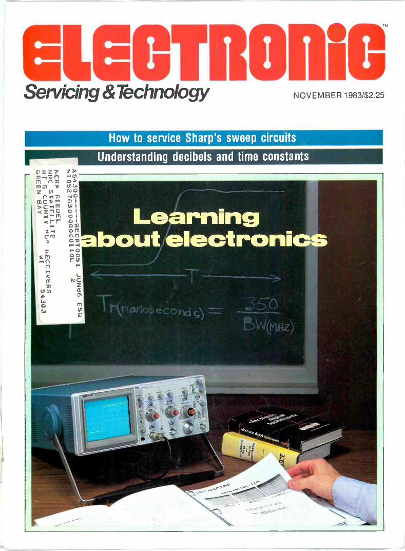
Electronics manuals, specsheets and specificinstruction handbooks areideal sources for updatingyour electronics knowledge.For other methods ofexpanding your knowledge,see "Learning aboutElectronics" on page 24.(Cover photo courtesy ofTektronix.)
10 How to service Sharp's sweep circuitsBy Homer DavidsonMost service problems originate in the sweep circuit ofcolor TV receivers. By knowing symptoms and cures forthese problems, Davidson focuses on some symptoms andprovides the cures for the supply, horizontal and verticalsweep problems.
24 Learning about electronicsBy Conrad Persson, editorIn today's rapid pace of electronics, keeping up with all ofthe electronics developments is of prime concern for theconsumer. For the service technician, it is just as vital tokeep updated and educated on troubleshooting techniquesand repair methods.
40 Using linear ICsBy Joseph CarrThe author discusses the construction of linear ICs, howthey are used and how to troubleshoot circuits that mightbe defective.
48 Test your electronic knowledgeBy Sam Wilson, ISLET test directorSee how you would do on the Certified ElectronicTechnicians' test. This month's questions cover powersupply.
50 Decibels and time constantsBy Sam Wilson, ISLETThe relationship of logarithms and the number calledepsilon help in explaining the equation for decibels and timeconstants.
52 Symmetrical output circuitsBy Bud Izen, CET/CSMThree basic variations of the complementary type of audiooutput circuit are examined as well as their advantages anddisadvantages in practical applications.
2 Electronic Servicing & Technology November 1983

Page 6
1
Page 46
Page 22
o in
R2
V+
V-
RS20K
V.
1 °
Departments
4 Editorial
6 Technology
22 Books
26 Feedback
28 Troubleshooting Tips
29 Profax
38 Readers' Exchange
56 Symcure
58 Products
61 Literature
Next month...
One of the more common items we see on the audioservicing bench is the cassette recorder. Although mostrepairs are the garden variety of clean-and-lube routines,occasionally we have to change a head or readjust theinternal controls to get the machine back up to itsoperating potential. Kirk Vistain describes some of theadjustments that most commonly require attention.
November 1983 Electronic Servicing & Technology 3
EditorialWv
Kill the umpire?One of the problems with athletic events is that
judging is done by mere humans, who are fallible.Even when officials are totally unbiased, theyoccasionally make mistakes. And have you noticedthat when they make a bad call it always goesagainst your team?
In international athletic competition, thedifficulties are compounded by nationalistic fervor.For example, according to researcher Joan deRegt of International Resource Development, anindependent consulting firm in Norwalk, CT,"Political controversies often arise when you havea Yugoslavian judge who awards a Soviet gymnastan undeservedly high score, while an Americanjudge might give that same gymnast anundeservedly low score. With the final outcomes ofthese events often decided by fractions of a point,it's a shame to see prejudice or political hagglingobscure true athletic accomplishment."
How do you eliminate the human factor injudging events such as this? Why, turn it over tothat electronic marvel, the computer, of course. Itwould work something like this. Computerizedimages for the ideal moves for the events would berecorded and made part of a computer database.When the athlete performs in competition, theperformance would be recorded and transformedinto computerized images, which would becompared with the record of the ideal routine. Thescore would be determined on the basis of thiscomparison.
According to de Regt, the use of such a systemis likely to occur "sometime within the next fouror five Olympiads," or roughly by the year 2000.
"It's not such a giant step to take," she says."Many physicians are already using such imagingsystems to analyze the mechanical factors involved
in sports injuries."This conjures up images of what might
eventually be if this type of judging system wereto be exploited to the fullest in all sports.
Just imagine in football, for example. We couldput an electronic device inside the football andinstall sensors in the field. There would be noquestion of whether the offense had made the firstdown, or whether the ball had broken the plane ofthe goal line for a touchdown.
But it's in baseball that electronics could reallydo the job. Wouldn't it be great to eliminate all theumpires? For starters it would be a simple matterto get rid of the guy behind the plate. We'dreplace home plate with a bar-code reading devicelike at the grocery store, and put bar codes on thebaseballs and bats. Not only would you know if theball was in the strike zone, you'd be able to detectwhether the pitch was a fastball, curve, slider orsinker. You could also tell how fast the pitch wasand if the batter swung early, late, high or low, orwhere he met the ball if he made contact. Sensorsalong the foul lines and base paths and at basescould take care of questions of fair or foul andsafe or out.
But then, who would fans have to boo when acall went the wrong way? And who would BillyMartin kick sand on when he got frustrated?Baseball just wouldn't be the same without thosemen in blue whom fans just love to hate.
In this increasingly automated and computerizedworld, some jobs are best left to humans.
9
ELGOTROHiC
Editorial, advertising and circulation cor-respondence should be addressed to: P.O. Box12901, Overland Park, KS 88212.9981 (a suburbof Kansas City, MO); (913) 888-4884.
EDITORIALBill Rhodes, Editorial DirectorNils Conrad Persson, EditorCarl Babcoke, Consumer Servicing ConsultantRhonda Wickham, Managing EditorTina Thorpe, Associate EditorJane Cigard, Associate Editor
ARTKevin Callahan, Art DirectorJoni Harding, Graphic Designer
CIRCULATIONJohn C. Arnst, DirectorEvelyn Rogers, ManagerDee Manses, Reader Correspondent
ADMINISTRATIONR. J. Hancock, PresidentCameron Bishop, PublisherEric Jacobson, Associate Publisher
ADVERTISINGGreg Garrison, National Sales ManagerLiz Turner, Production ManagerRobyn Kahn, Marketing Coordinator
Member, Audit Bureauof Circulation
'ABPMember, American
Business Press
ELECTRONIC SERVICING & TECHNOLOGY (USPS 462-050)(with which is combined Electronic Technician/Dealer) ispublished monthly by Intertec Publishing Corp., 9221Ouivira Road, P.O. Box 12901, Overland Park, KS
66212-9981. Second Class Postage paid at Shawnee Mis-sion, KS 66201. Send Form 3579 to P.O. Box 12952.Overland Park, KS 66212-9981.
ELECTRONIC SERVICING & TECHNOLOGY is the "how-to"magazine of electronics. It is edited for electronic profes-sionals and enthusiasts who are Interested In buying,building, Installing and repairing home -entertainment elec-tronic equipment (audio, video, microcomputers, electronicgames, etc.).
SUBSCRIPTION PRICES: one year $15. two years $26,three years $34 in the USA and its possessions. Foreigncountries: one year $20, two years 530, three years $40.Single copy price $2.25; back copies $3.00. Adjustmentnecessitated by subscription termination to single copyrate. Allow 6 to 8 weeks delivery for change of address.Allow 6 to 8 weeks for new subscriptions.
PHOTOCOPY RIGHTS: Permission to photocopy for Internalor personal use is granted by Intertec Publishing Corp. forlibraries and others registered with Copyright ClearanceCenter (CCC), provided the base fee of $2 per copy of arti-cle is paid directly to CCC, 21 Congress St., Salem, MA01970. Special requests should be addressed to CameronBishop, publisher.ISSN 0278-9922
INTERTEC PUBLISHINU CORP.
F1983 All rights reserved.
The Digitalvs. Analog
battle is over.
85*
buys you the new champion.
The new Fluke 70 Series.They combine digital and analog displays for
an unbeatable two -punch combination.
Now, digital users get the extra resolution of a
3200 -count LCD display.
While analog users get an analog bar graph for
quick visual checks of continuity, peaking, nulling
and trends.
Plus unparalleled operating ease, instant
autoranging, 2,000+ hour battery life and a
3 -year warranty.
All in one meter.Choose from three new models. The Fluke
73, the ultimate in simplicity. The feature -packed
Fluke 75. Or the deluxe Fluke 77, with its own
multipurpose protective holster and unique
"Touch Hold" function (patent pending) that cap-
tures and holds readings, then beeps to alert you.
Each is Fluke -tough to take a beating.
American -made, to boot. And priced to be, quite
simply, a knockout.
For your nearest distributor or a free brochure,
call toll -free anytime 1-800-227-3800,Ext. 229. From outside U.S.. call 1-402-496-1350, Ext. 229.
FROM THE WORLD LEADERIN DIGITAL MULTIMETERS.
Fluke 73 Fluke 75 Fluke 77$85' $99' $129'
Analog/digital display Analog/digital display Analog/digital display
Volts, ohms. 10A, diode Volts, ohms, 10A, mA, Volts, ohms, MA, mA,
test diode test diode test
Autorange Audible continuity Audible continuity
0.7 % basic do accuracy Autorange/range hold "Touch Hold" function
2000+ hour battery life 0.5 % basic do accuracy Aulorange/range hold
3 -year warranty 2000+ hour battery life 0.3% basic dc accuracy
3 -year warranty 2000 +- hour battery life
3 -year warranty
Multipurpose holster
Suggested U S. list price, effective October 1 198
'1993 John Fluke Mfg. Co . Inc. All rights reservedCircle (5) on Reply Card
FLUKE
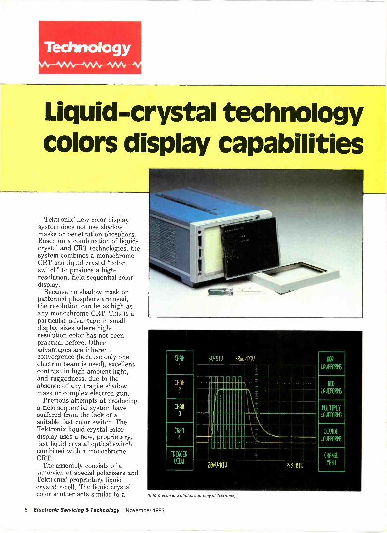
Liquid -Crystal technologycolors display capabilities
Tektronix' new color displaysystem does not use shadowmasks or penetration phosphors.Based on a combination of liquid -
crystal and CRT technologies, thesystem combines a monochromeCRT and liquid -crystal "colorswitch" to produce a high -resolution, field -sequential colordisplay.
Because no shadow mask orpatterned phosphors are used,the resolution can be as high asany monochrome CRT. This is aparticular advantage in smalldisplay sizes where high -resolution color has not beenpractical before. Otheradvantages are inherentconvergence (because only oneelectron beam is used), excellentcontrast in high ambient light,and ruggedness, due to theabsence of any fragile shadowmask or complex electron gun.
Previous attempts at producinga field -sequential system havesuffered from the lack of asuitable fast color switch. TheTektronix liquid crystal colordisplay uses a new, proprietary,fast liquid crystal optical switchcombined with a monochromeCRT.
The assembly consists of asandwich of special polarizers andTektronix' proprietary liquidcrystal 7r -cell. The liquid crystalcolor shutter acts similar to a
CH N
1
CHRIS
2
CHAN
3
CHAN
4
TRIGGER
VIEW
SV/DIV 50mV/DIV
2011/DIV 2mS/DIV
AOR
LIVEFORhS
ADD
KERNSRPS
t1JLTIPLY
WAUEFORM5
DIVIDE
WRUEFORPS
CHANGE
INN
(Information and photos courtesy of Tektronix)
6 Electronic Servicing & Technology November 1983

OR
REACRELI
Wow
.4,zocu,.s>
ID s#.>RCA
Jt
Y IV
ORITY
1
#
rten
RCA Distributor andSpecial Products Division, Deptford, NJ 08096
filter that switches between twostates, one allowing primary color#1 to pass and the other passingprimary color #2. The shutterswitches between the two statesin a few milliseconds upon theapplication of a low voltageelectrical drive signal.
The CRT has a simple phosphorwith two separate emission peaksthat are typically, but not limitedto, red and green. The phosphordoes not require any patterningor special process steps. In anyone field, the information writtenon the screen appears only in thecolor selected by the electronicswitch. Each color is repeated ata 60Hz rate, requiring the 2 -fieldsystem to run at a 120Hz rate.This field -sequential system canprovide all possible mixtures of
the two primary colors containedin the phosphor.
Research is continuing toextend the concept to threefields, with three primary colors,which will produce a full colorgamut comparable to or betterthan conventional color displaytechnologies.
Examples of where this newtechnology can provide colorcapability where it has not beenpractical before include: Small instrument displays, such
as oscilloscopes, logic analyzersand spectrum analyzers. In thepast, the need for highresolution to present waveforminformation has been adrawback. Now,Tektronix'liquid crystal color display'sability to function in
both refresh vector andraster display modesmakes new designbreakthroughs possible.
Small process control displays,such as those included onvacuum systems, can nowinclude color for highlightingspecial situations andwarnings.
Computer workstations, wherehigh -resolution is important.
Word-processing equipment,where monochrome displayshave been typically usedbecause high -resolution colordisplays have either not beenpossible or too expensive.Tektronix' liquid crystal colordisplay technology allows theaddition of color without anyresolution penalty. ewe
Order Your INTERTEC Mailing Labels NOW and
SAVE!To take advantage of these savings, your list rental must becompleted and billed by December 31, 1983, or discountoffers do not apply.
110% DISCOUNT FOR USE OF UP TO 10,000 SUBSCRIBER NAMES 5,000 name minimum
2 Sample mailing piece required
LARGER 15% DISCOUNT WHEN YOU RENT MORE THAN 10,000 NAMES Sample Mailing piece required.
Because we want your business NOW, we're making you an offer we've never made before. INTERTEC PUBLISHINGCORP. has successfully served various markets (including this one) for over 95 years. Each magazine's subscriber listoffers unparalleled direct marketing opportunities.
List of Publications: Broadcast Engineering, Electronic Servicing & Technology, Grounds Maintenance, Implement &Tractor, Land Mobile Product News, Lawn & Garden Marketing, Video Systems.
For further information, call Rosanne Navran, Directing Marketing Co-ordinator, TODAY!
"'atye"I NTERTECPUBLISHINGCORP.
(913) 888-4664 P.O. BOX12901OVERLAND PARK, KS 66212
8 Electronic Servicing & Technology November 1983

BokerCrescentLufkin®NicholsonPlumbWeller, Wiss®
Take a good look round this ad andyou'll agree that "All together" is noexaggeration. Whether you're makingor mending. cutting or joining, striking,measuring or stripping, there's a Coopertool that's just right for the job. Don't takechances on tools. Specify Cooperand get 'em right the first time! Plumb
The Cooper Group PO Box 728 Apex NC 27502 USA Tel (919) 362-7510 Telex 579497
Coo s erTools)Circle (7) on Reply Card

How to serviceSharp's sweep circuits
By Homer L. Davidson
In color TV receivers, most ser-vice problems originate in thesweep circuits or the power sup-plies. This certainly is true in 13inand 19in models by Sharp.
These models (Photofact 1959-2,for example) have several dc -
voltage supplies produced by rec-tification of horizontal -sweep pulseor scan peaks. These voltagesources are stabilized by regula-tion of the + 120V that is suppliedto the horizontal -output transistor.However, the situation is com-plicated by two limitations. Atturn -on, no horizontal sweep isgenerated, although it is necessaryfor proper operation of the + 120Vsupply. This same + 120V is essen-tial for proper operation of thehorizontal sweep. These contradic-tions are resolved through a seriesof small steps. An insufficient+ 120V supply at turn -on allowsthe horizontal sweep to operateweakly. The weak sweep increasesthe + 120V actual voltage, whichin turn strengthens the sweep, un-til the sweep is maximum and theregulated voltage is + 120V. Youmust consider this interdepen-dence of horizontal sweep andregulated voltage in troubleshoot-ing of these two basic systems.
Low voltage and regulationFigure 1 shows the complete
low -voltage sources and + 120Vregulation for Sharp model C1935(Photofact 1959-2). In normaloperation of this circuitry, the full+ 164V from the bridge rectifier isapplied to the SCR701 anode.SCR701 is gated into conductionby the I701 power -regulator IC ata time during each horizontal -sweep cycle as required to providea constant + 120V at integratingcapacitor C708. An SCR, once it isgated on, continues conduction un -
on%R702
F701SW7O1 3.32
10W6.
120V
AC
OPEND702
C70101
D701
T602FLYBACK
300V PPNEG PULSE-
164V
D704
D703
SCR701C709 REG
0033 -r
R70468052
2W
LEAKY
A
ZD70111
+ 163VR705
150
G +119V j
+120V7 +8.3V -
'C708 ,100µF
R706100K
C710 R710 R711047 33 680
1701
POWER REGULATOR
5
R707120V All C711
10000 R709 .01.7-R7135600 2 18K
3
R712
12K
1602FLYBACK
10
oc 6 R520I
Pc*2zw
6 + 18V
R3018201W
R611
8200
D452.
R454
120
R
D705 3325715
>I '//OPEN
LEAKY
+48.7V
C506 SOURCE
47µ F
C706 .
470145
C301222µF,
C4591µF
C802 I C714 tt470µFY410µFJ_
C713 y47µF
+117VSOURCE
w +120VSOURCE
+9.82VSOURCE
IHORIZ OSCJ
+12.13VSOURCE
3. +18VSOURCE
Figure 1. A bridge rectifier and C706 produce a filtered + 164V supply that isregulated to + 120V by SCR701 and 1701.
10 Electronic Servicing & Technology November 1983

THINKING TVRO?Take A Look At Winegard:
O 2 4 E: Ei 10WINEGARCI SATELLITE RECEIVER
POWER SCAN POLARITY
AUDIO. TUNE
,r \SIGNAL STRENGTH FINE TUNE SAT SELECT
Excellent picture quality and low cost. That's what you get wits Wiregard's SC-500CS home satel ite television system.You'll discover that Winegard's 8 -foot package incorporates all the latest in TVRO solid-state design and engineering for a dramatic difference in satellite TV reception. All thefeatures that your customers want are there!
WINEGARD sn
Why Buy Winegard Home SatelliteTV Reception Products?
All Your Satellite PrDduct Needs From OreSource Competitive Pricing Easy to
Handle, Ship anc Inventory All SatelliteProducts Backed By A Full -Year Warranty Easy -To- nstall Complete And ProfessionalFactory Support Anc Service Rigid Qual tyControl Standards For Satellite TV Products
SC -7032S RECEIVER FEATURES:
Rapid Scan Control Polarity Switch Audio Tune Signal Strength Me-er
Fine Tune Charnel Select Control Eatel ite Select F emote Control Optional
SC -8009 ANTENNA FEATURES: 8 -ft. Durable SpLr Aluiiinum Reflector wits
Weather Resistant `tifite Epoxy Finish Easy Handling and Stopping Complete Arc Coverage Choice of Rugged Pedestal or Post Polar Mounts Prime FDcus Feed with Automatic Electronic Polarity
Switching 90mph JJind Surviva
SATELLITE SYSTEMS ,,4 w se foal saterseon about SASA, wtheprofessional satellite TV installers network.
WINEGARDCOMP4NY 3000KIRKWOODSTREET BURLINGTON,10WA52601 (319)753-0121
Circle (8) on Reply Card
November 1983 Electronic Servicing & Technology 11

til the anode voltage becomesnegative relative to the cathode.Negative -going horizontal -sweeppulses from the flyback (pins 1 and11) turn off SCR701. Power is ap-plied to C708 from SCR701's rec-tification of these same negative -going pulses as well. Of course, allSCRs can be efficient rectifierswhen supplied with proper gatingand anode/cathode voltages. The+ 164V applied to the SCR701anode changes the zero -voltagepoint of the anode negative -goingpulses. Therefore, most of thepulse height is positive (ratherthan the usual negative) and it isrectified by the SCR701 anode/cathode diode action. C708 in-tegrates these two source voltages(gated dc from the + 164V plusrectified dc from the SCR) into anaverage voltage. When SCR701 isgated -on at the proper time duringeach horizontal cycle, a constantregulated voltage is produced.
It should be clear now why an in-sufficient voltage of about + 76V isobtained from the + 120V supplywhen there is no horizontal sweep:Without the SCR701 anode pulses,one of the power sources is miss-ing, and the regulator gates -on theSCR at incorrect times.
Of course, the + 120V regulatorcannot operate correctly unless itis supplied with + 164V from thebridge diodes that rectify the 60Hzline power. You should verify thepresence of + 164Vdc at theSCR701 anode before you wastetoo much time checking theregulator circuit.
A lower -than -normal supplyvoltage is obtained for thehorizontal -oscillator circuitthrough R611 from the + 120Vsource during start-up (or whenthe horizontal -sweep system isdead). When correct start-up ac-tivates the + 18V source (from rec-tified horizontal -sweep power),D452 is forward biased and theoscillator voltage comes throughR454, producing + 9.82V supplyfor the oscillator. In other words,oscillator supply voltage comesthrough R611 during start-up andthrough R454 during normal runoperation.
Figure 2. Arrows point to important components on the circuit board of a Montgom-ery Ward GSK12981B manufactured by Sharp. Clockwise from upper left, arrows in-dicate SCR701 heat sink, heat sinks for vertical output Q502 and Q503, 1501, 0602horizontal output, and the T602 flyback with focus and screen controls.
VIDEO 16
VERT
SAW FROMYOKE CURRENT
y
1501
SYNC SEPARATORDEFLECTION PROCESSOR
C6011_.0056
R60147
C602+1µF1
HORIZPULSES
2
R606
12K
R607680
R608HORIZHOLD2000
13
R5011200
VERT
DRIVE TOQ501
A
10
C5020.68
+9.82V
R50439K
R503VERT
HOLD100K
+12.13V
HORIZSQUARE WAVES
TO Q601 BASE
Figure 3. Solid-state components for sync separation, horizontal phase detector,horizontal oscillator and vertical oscillator are inside IC 1501.
The de power for the horizontal- source at all times. However, atdriver and horizontal -output tran- turn -on before start-up is com-sistors comes from the + 120V plete, this voltage is less than
12 Electronic Servicing & Technology November 1983

SAMSBOOKS ANDSOFTWARE
1
SAMSQUICKFACTSTIME SAVING SERVICE HINTS
SONY TVVoI.1
MMeh OP<000 Thou [P 1230.rV.1l00U70,u02
MAKE A FAST BUCKWITH QUICKFACTS.Now for a limited time, you can take an additional$5.00 off the already -reduced prices on SamsQUICKFACTSTM!
Sams QUICKFACTS is the only PHOTOFACT®-based, quick and easy, one -stop reference to TVservice repair. It provides you 1,500 money-making, time -saving tips on repairing the majorTV brands, including:
Trade Name Volume No. Price
ZenithMagnavoxRCA, Vol. 1RCA, Vol. 2General ElectricSearsSylvaniaSonyJ.C. Penney, Vol. 1J.C. Penney, Vol. 2PhilcoAdmiralQuasarPanasonic
5900 $34.955901 $34.955902 $39.955903 $39.955904 $39.955905 $39.955906 $39.955907 $39.955908 $39.955909 $39.955910 $34.955911 $34.955912 $34.955913 $34.95
Each QUICKFACTS volume covers a single brandname with all chassis numbers organized by
G?ÚkFqc-rs,n
4271"0JS,
circuit category, making it easy to identifyproblem component areas. In addition, detailedschematics help you quickly locate and replacedefective parts. You work faster and moreeffectively. And that means improved service foryour customers and greater profits for you.
TWO WAYS TO SAVEGet $5.00 off the already -reduced price on SamsQUICKFACTS by simply cutting out the certificatebelow and presenting it to your local Samsdistributor. If you don't have a Sams distributor,order direct and mail Sams the form provided.Order as many QUICKFACTS volumes as youlike but limit one coupon per customer, please.
Save big on Sams QUICKFACTS today and startmaking the big bucks in TV servicing!
$5.00 OFF
ANY SAMS QUICKFACTS VOLUME.(Limit one coupon per customer. Non-transferrable. May not be duplicated.
Not valid after 2/29/84.)ATTENTION: DISTRIBUTOR
Return to Howard W. Sams & Co., Inc. for credit.
MAIL TO: HOWARD W. SAMS & CO., INC., 4300 West 62nd Street, P.O. Box 7092, Indianapolis, IN 46206
Please send me the following QUICKFACTS:
Quantity Volume No. Price Total SHIP TO:
Payment Enclosed
SubtotalSubtract S5.00 times Qty. of books
Add Local Sales Tax Where ApplicableAdd Shipping and Handling
Total Amount of Order
Check [] Money Order VISA Li MasterCard
2.00
-1
Account No
Expiration Date
Name (print)
Signature
Address
City State Zip
Call 800-428-3696 or 317-298-5566 for the name of your local Samsdistributor or to order by phone. Ask for Operator 466.
Offer good in USA only and expires 2/29/84. Prices subject to change without notice AD466
QUICKFACTS and PHOTOFACT are trademarks of Howard W Sams & Co., Inc.
Circle (9) on Reply Card

+ 80V. The low oscillator, driverand output start-up voltages canproduce only weak sweep, evenwith a non -defective receiver. Ifstart-up is not completed becauseof a sweep defect (or if start-up isfollowed immediately by shut-down), some of these stages mighthave a weak signal plus typicallylow start-up do voltages.
The following are helpful sug-gestions for analyzing supply prob-lems: Loss of horizontal sweep at the
T602 flyback eliminates thehigh voltage, CRT screen vol-tage, CRT focus voltage, + 171Vboost supply, + 12.13V source,+ 18V source and the + 48.7Vsource.
Loss of all + 120V source alsoeliminates the + 117V sourceand the horizontal oscillatorstart-up source voltage.
The + 117V source supplies onlythe sound -output transistors.
The + 171V boost source sup-plies only the red, blue andgreen output transistors thatdrive the CRT cathodes.
The + 120V regulated sourcesupplies the horizontal -outputtransistor directly, the drivertransistor through a droppingresistor, the + 117V sourcethrough a resistor and the oscil-lator start-up voltage throughR611.
The horizontal oscillator oper-ates after start-up from the+ 9.82V source.
The + 12.13V source suppliesthe vertical oscillator, somevideo and chroma stages and theIF stages.
The + 18V source supplies thesound IF stages and somechroma functions. Also, it sup-plies the + 12.13V source(through resistors) and the hori-zontal oscillator start-up volt-age.
Two vertical -output transistorsoperate from the + 48.7Vsource.
Servicing power suppliesHigher -than -normal voltages in
the + 120V source can be causedby leakage in SCR701 or C709
FROM
1501
PIN 4
R6091800 0.001
Q601 HORIZ DRIVER +79VT601
R610 DRIVER
180 +0.41V
C611
+9.82V
R6124700
C6120.001
R6141500
+ 120V
HORIZ
Q602 OUTPUT
R6150.271W
+119.1Vt ANDTOYOKE
1 FLYBACK
C615 00009T602
0.0039
OPENS
Figure 4. The horizontal driver and output stages are not unusual, except for thedamper diode inside the Q602 transistor case and emitter resistor R615, whichsometimes causes a motorboating of the + 120V supply.
(0.0033µF), which feeds a steadycurrent from the + 164V supply tothe + 120V supply. A shortedZD701 zener can maintain SCR701in constant conduction. Also, adefective I701 regulator IC canproduce excessive + 120V sourcevoltages, although this is rare.Another possibility is increasedresistance in R706 (Figure 1).
Most SCR701 leakages can befound with a high -power ohm-meter (low -power mode voltage isnot sufficient to check gate -to -cathode diode action), however theSCR should be removed from thecircuit during the tests. Normalresistance between gate andcathode might measure 500 toperhaps 9000, depending on the
ohmmeter used. Notice, however,that the ohmmeter polarity mustapply the positive probe to thegate and the negative probe to thecathode. Resistances betweenanode and cathode or gate shouldbe very high, perhaps above 5M0.
Low voltage from the + 120Vsupply can be caused by these con-ditions: a low + 164V line -rectifiedsupply voltage, an increasedresistance in R709, decreasedR706 resistance or a loss ofhorizontal sweep.
Always remember that no morethan + 76V can be obtained fromthe + 120V source unless thehorizontal sweep is operating cor-rectly.
Loss of all voltage in both the
14 Electronic Servicing & Technology November 1983

SPECIAL PUBLICATIONSNOW AVAILABLE
FROM SONY! A collection of books on key concepts, in-depth theory of circuit operation and troubleshooting -aid for the following
three categories of Sony products: AUDIO, BETAMAX, TV.
The material is presented concisely. These books, although written for the average to advanced technicians, can beused as a self-help guide by anyone who is interested in Sony consumer products.
MODEL & DESCRIPTION
TV ProductsAlpha -1 Chassis New Circuit OperationAlpha -1 Chassis Troubleshooting Guide30P Chassis New Circuit Operation30P Chassis Troubleshooting Guide
WaBetamax ProductsSL 5400 System Control and Troubleshooting Guide
HMI SL-2500 New Circuit OperationSL -5800 New Circuit OperationAG -400 Auto Changer Circuit OperationHVC-2000 Circuit OperationHVC-2400 Circuit OperationTrinicon Color Cameras
l 1-
Audio ProductsPS -X65, -X75 Circuit Operation and Troubleshooting
GuidePS -X700, -X500, -LX5 Circuit Operation and
Troubleshooting GuideCRF-1 Theory of OperationSTR-VX6, -VX5, -VX4, -VX3, -VX2, -VX1 Circuit
OperationSTR-V55, -V45, -V35, -V25 Circuit OperationST -J75 Circuit Operation and Troubleshooting GuideRS -20 Circuit OperationPCM-F1 Troubleshooting GuideCDP-101 Troubleshooting Guide
47'MiscellaneousRF Interference HandbookDigital ElectronicsRemote Control System
PARTNUMBER PRICE
2CTV480-22CTV1080-12CTV681-12CTV1181-1
$5.005.007.007.00
2BETA180 1 $3.002BETA982 1 5.002BETA681-1 3.002BETA1182-1 3.002CC1281-3 10.00T-999-714-31 5.002CC383-1 10.00
2HF181-5 $5.00
2HF1282-2 5.002HF1082-4 3.00
2HF1181-1 5.002HF481-2 5.002HF781-4 5.002HF782-1 3.009-959-013-11 3.009-959-021-11 3.00
2TV990-1177-1 $5.002G183-1 8.002RM383-1 3.00
SONY®TO ORDER: Send check or money order payable to "Sony Corporation of America" and mail to:Sony National Parts Center, 8281 NW 107th Terrace, P.O. Box 20407, Kansas City, MO 64153
FOR FURTHER INFORMATION: Contact Lloyd Barningham,Tel. (816) 891-7550
Circle (10) on Reply Card
November 1983 Electronic Servicing & Technology 15

+ 164V and + 120V sources usuallyindicates that a strong overload(such as a shorted horizontal -output transistor) has blown theF701 4A fuse, or opened 3.34R702. A shorted bridge rectifieralso can ruin these two com-ponents, as can a shorted C706main filter capacitor.
Horizontal -sweep problemsI501 deflection -processor IC
(Figure 2, arrow at far right) con-tains the solid-state transistors forthe horizontal and verticaloscillator circuits. A partialschematic is shown in Figure 3.Composite video comes into I501at pin 16. The sync is separated in-side I501 and applied to an internalphase detector. Horizontal pulsesare integrated into sawteeth byR602, C602, C601 and R601.These sawteeth enter I501 at pin 1where they are applied to thehorizontal phase detector.Remember that sync and horizon-tal sawteeth are equally essentialfor solid locking and correct fre-quency. Whenever horizontal fre-quency is unstable, scope thesesignals at pins 16 and 1.
Horizontal -frequency squarewaves exit I501 at pin 4 and areapplied to the Q601 base (Figure 4)as input signal and do positive for-ward bias. Q601 inverts andamplifies the drive signal, and thisstronger signal is coupled andimpedance -matched by T601driver transformer, which in turndrives the base of Q602, thehorizontal -output transistor. Q602then supplies sweep power to thedeflection yoke and the T602flyback.
Notice that the horizontal -output transistor is not a conven-tional type, but it has the damperdiode inside the transistor case. Donot attempt to substitute a com-mon type that does not have thediode. The transistor will fail whenthere is no damper diode. If possi-ble, replace Q602 with the original25D870 or 25D869 component.
All signals of the Figure 3 andFigure 4 circuits can be scopedsafely, which makes the scope theinstrument of choice for testing
R65568
20V PP POS PULSES 8474 D651
FROM T602 op. ,FLYBACKPIN 10 R621
0.47
TO CRT HEATER
ryNC652 I R653
4.7µF Y 10K
+ 17.4V
R652 ZD651
TO 10K OV %1501
PIN 3 C651 + R651lOµFY 15K
Figure 5. Horizontal pulses from the T602 flyback are rectified by 0651, and thepositive voltage is stored in C652. When the pulse amplitude (and the high voltage) isnot excessive, the dc voltage does not exceed the 20V ratings of the ZD651 zenerdiode so no positive voltage passes through R652 to reach 1501 pin 3. When the highvoltage is excessive, voltage passes through ZD651, making pin 3 positive and the IClatches to remove the horizontal -drive square waves. Without drive to the 0601 drivertransistor, the horizontal sweep is killed, and this also removes all scan -rectifiedpower sources, eliminating the picture and sound.
these horizontal stages. Scope thehorizontal signal path startingwith I501 pin 4 and continuing tothe Q601 base, the collector ofQ601, the Q602 base and finallythe Q602 collector. When youlocate the first missing ordistorted waveform, you haveisolated the problem to the circuitstage just prior to that point.
In a number of sets, resistorR614 (Q601 collector voltage,Figure 4) has become open, remov-ing the collector voltage andsignal. A dc -voltage reading ofabout + 9V without any squarewaves at I501 pin 4 usually in-dicates that the IC is defective andshould be replaced. Low do voltagereadings at other I501 pins alsocan point to a defective IC.
Frequently, when a Q602 outputtransistor shorts, emitter resistorR615 burns from the overload.After a new Q602 is installed, theweakened resistor can cause apulsating voltage in all supplies
taken from horizontal -sweeppower.
Horizontal shut -down operationIn theory, any time the high
voltage becomes dangerously high(producing X-rays), an X-ray pro-tection circuit should immediatelyreduce the high voltage to a safevalue. However, none of the late -model color receivers do that. In-stead, the horizontal sweep iseliminated, along with the highvoltage, the raster and the picture.Most circuits maintain this condi-tion until the power is shut off. Ifthe overvoltage condition thattriggered the shut -down is not per-manent, the performance can berestored by turning off thereceiver power for a minute andthen switching it back on. Ofcourse, if the overvoltage condi-tion is still present, the start-upwill be followed instantly by shut-down.
A schematic of the Sharp shut -
16 Electronic Servicing & Technology November 1983

Thecomplete libraryof replacement semi's.
ECG212LECGSuppsasd Prics $3.25
SemiconductorsMaster Replacement Guide Entertainment Industrial Commercial Equipment Maintenance and Repair
Sylvania Electronic Components
Eere's the one guide that has it all-the new ECG' Master Guide. It's 545 pages,packed with over 3000 ECG semiconductors that replace over 200,000 industry
numbers. And our replacements meet or exceed the specs of the original parts.So if it's ECG, you can count on it to fit and work.
Reduce equipment downtime and save yourself endless hours of partshunting. For everything from analog amplifiers to zener diodes, go with
replacement semiconductors from ECG. Get your new ECG MasterGuide and our "Counterpoints" product updates from your nearest
If it's ECG, it fits. distributor. For his name and number, call 1-800-225-8326 toll -free(in yMassachusetts, dial 1-617-890-6107). Or just send $3.25 for
Arad it works. your ECG Master Guide to PhilipsECG, Inc., Dept. EST,70 Empire Drive, West Seneca, NY 14224.
PhilipsECGA North American Philips Ccmpany

down circuit is shown in Figure 5.Pulses from the flyback windingthat supplies CRT -heater powerare rectified by diode D651, pro-ducing about + 17V to + 18V. C652acts as a peak -reading filtercapacitor and also stores thevoltage for a time to prevent er-ratic operation. Unless the flybackpulses are abnormally high, theC652 do voltage does not goanywhere, because the 20V ratingof zener diode ZD651 is not ex-ceeded. Therefore, the zeneranode and I501 pin 3 have zerovolts, permitting normal oscillatoroperation.
If the flyback -pulse amplitudesincrease abnormally for anyreason (such as an open retrace -tuning capacitor or excessiveregulated voltage), the ZD651zener voltage is exceeded, forcingpositive voltage through ZD651,R652 and I501 pin 3. Thiseliminates the output square wavesat I501 pin 4. Without a drivesignal, the horizontal -sweep circuitstops all operations, whicheliminates raster, picture andsound; the receiver becomes total-ly dead.
A receiver that appears to be inshut -down mode presents severalproblems to technicians. The firstdecision is whether the shut -downaction has occurred because theflyback pulses were excessive (theonly valid reason for shut -down),or whether the shut -down circuititself has a defect that triggersshut -down when no problem existswith excessive high voltage orpulse amplitude.
It is easy to defeat the shut -downcircuit (but this is not recom-mended, as it could result in dam-age to the set). Turn off the ac pow-er, ground pin 3 of I501 and turn onthe ac power. That's all. If thereceiver previously had been inshut -down because of a defect inthe shut -down circuit, the receivernow should operate correctly, in-cluding all supply voltages and thehigh voltage.
If excessive high voltage hadcaused the shut -down, the receivershould operate, but with possibledanger from picture -tube damage
Figure 6. The new T602 flyback is shown mounted on the Sharp chassis, while the oldflyback is at the left. Use only original -type replacements.
before the power can be turnedoff. If you are willing to take thatchance, and the receiver has soundand soon shows a picture, quicklytest for + 120V at the collector(case) of Q602 and then measurethe high voltage. In case bothvoltages are normal, the problemevidently is a defect in the shut-down circuitry. Measure all shut-down components, particularlyD651 and zener ZD651.
A safer method for provingwhether or not shut -down is occur-ring and if it is from excessive highvoltage is to operate the chassisfrom a variable -voltage 60Hztransformer. Start with about 50Vac and slowly increase thevoltage until picture and sound areobtained. Again, slowly increasethe ac voltage and notice if shut-down occurs (and at what linevoltage). A normal receiver shouldwithstand up to almost 130Vbefore the shut -down activates.Shut -down at 90V to 100V hints atexcessive + 120V regulated sup-ply, while shut -down at 100V to110V might be caused by an opencapacitor such as C615 and C620 inFigure 4.
When the + 120V supply voltagecannot be adjusted by R107 to thecorrect voltage, R107 might bedefective. With power off, rotate it
and check the resistance.
No sound, no horizontal sweepWhen the receiver is completely
dead, check the Q602 collectorvoltage. A reading of less than+ 70V hints at a defective bridge -rectified + 164V supply, while a+ 76V or + 78V reading indicatesthe horizontal sweep is notoperating (the low voltage iscaused by the lack of horizontalpulses at the SCR701 anode).
An open Q602 output transistorwith an ohmmeter can have com-plications because of the internaldamper diode. First, a voltage -drop diode tester or a high -powerohmmeter should be used to checkthe transistor out -of -circuit.
When the horizontal -outputtransistor does not have an inter-nal damper diode, the resistancereading between collector andemitter should be high, regardlessof probe polarity. But the damperdiode in Q602 should give a typicalsilicon diode reading when thepositive probe touches the emitterand the negative ohmmeter probetouches the collector. With theprobes reversed, the readingshould be in the megohms. Lowerreadings should arouse suspicionsabout the transistor.
The base/emitter and base/col-
18 Electronic Servicing & Technology November 1983

FOUR GREAT REASONSTO USE N.A.P. FACTORYREBUILT MODULES.
1. ONLY N.A.P. rebuilt mod-ules are always updated byour engineers to incorporatethe most recent factory mod-ifications.
2. ONLY N.A.P. guaranteesgenuine, factory approved re-placement parts-pre-testedto exacting quality controlstandards before installation inmodules.
3. ONLY N.A.P. providesmodules tested to demandingfactory quality assurancestandards.
4. ONLY N.A.P. guarantees re-built modules that perform torigid factory specifications. OurOne -Year Warranty proves it.
Product Services OrganizationP.O. Box 555, Dept. 741Jefferson City, TN 377601-615-475-3801, Ext. 7348
CONSUMERELECTRONICSCORE
PRODUCTSERVICESORGANIZATION
MAGNAVOXODYEYPHILCOSYLVANIA
1
A North American Philips CompanyCircle (11) on Reply Card
November 1983 Electronic Servicing & Technology 19

R515
lector junctions should be checkedwith both polarities in the sameway. Forward -biased junctionsshould show typical resistances forthe meter used, while reverse -biaspolarity should produce resistancereadings approaching infinity.
If Q602 tests normal, but thehorizontal sweep is dead, check allsignificant do voltages followed byscope analysis of any or allwaveforms in the horizontalsystem. These measurements andsome logical thinking locate theproblem area.
Check all connections of theT602 flyback transformer on thecircuit board's bottom side. Poorconnections, particularly pins 1
and 11 for the SCR pulses, havebeen found there. Flybacks mayrequire replacement (Figure 6).
MotorboatingWhen the + 120V regulated sup-
ply voltage varies significantly at aslow rate, causing a motorboatingsound in the speaker and a syn-chronized slow variation of picturewidth, replace resistor R615, theQ602 emitter -to -ground resistor(Figure 4). R615 is likely to needreplacement after Q602 hasshorted and been replaced. Use a0.272, 1W replacement for R615.
Vertical -sweep problemsTransistors for the vertical
oscillator are inside I501. Theseare followed by a driver transistorand two NPN power transistorsthat supply vertical power to theyoke. It is important to note thatthe driver transistor is external tothe IC in Sharp models (Figure7A), while the transistor is insidethe IC in similar models manufac-tured by Sharp for MontgomeryWard and K -Mart (Figure 7B). Pinnumbers for the vertical -hold con-trol and drive -signal output aredifferent for the two versions, asshown.
Scope waveforms can prove thepresence or absence of signal fromI501 on to the yoke, and this isvaluable. However, defects oftendistort the waveforms, makinganalysis difficult. Lack of a drivewaveform at the proper pin (accor-
Q501 DRIVER
VERT
HOLD
1501
DEFLECTION
PROCESSOR
8
VERTHOLD
INTERNALDRIVER
150
TO OUTPUT
Q503
BASE
0. TO OUTPUTQ502
BASE
Figure 7. (A) In Sharp chassis, the vertical driver transistor (0501) is external to 1501,while Montgomery Ward and K -Mart color receivers made by Sharp (B) include thedriver transistor inside 1501. Notice the different pin numbers.
ding to the circuit variations)might indicate a defective I501.Before removing the IC, measurethe supply voltages at the input toR502 (at the vertical -hold con-trol; + 12.13V expected) and atI501 pin 15 (expect + 9.82V). Ifthese two voltages are withintolerance and there is low devoltage and signal level at the out-put pin (pin 2 or 7), I501 should bereplaced.
Output transistors Q502 andQ503 have been known to cause in-termittent height when they openerratically. These intermittenttransistors cannot always be foundby in -circuit or out -of -circuit tests.Therefore, if they are suspected,replace both of them at the sametime. Use the exact replacement,or use ECG373 universal tran-sistors (Figure 8).
Erratic height also can be caused
Figure 8. (Arrows at the top point tovertical -output transistors 0502 and0503. At the bottom, an arrow points toSCR701 on its heat sink.
by corrosion on the vertical hold -control element. Spray the insidewith tuner cleaner and rotate thecontrol several times. If thisreduces the erratic action, youshould replace the control.
20 Electronic Servicing & Technology November 1983

LLtLLLt'LiLLLLLE1L LLLííL
1SE X NUMEiE.HS OR SPEL.IAI S
SiliconH .V. TriplersH IGH VOLTAGEMULTIPLIERSMinimum 3/may asst.
Cordless TelephoneX-18
$9995
X-19;7995less intercom
Range 600 tt. with 2 -way intercom Both receive and send calls from remote oration High -Low rechargeable battery indicator
alk=31/2 Digit DMMs637s EW!Reg. $7500 1'1Model 2806
X-25
0 7% DCV accuracy 500 hours continuous battery me Auto-ranging/manual ran4mg on
Volt and Ohm scales to A AC and DC ranges
3'V digit LCD display withannunciators
Single rotary switch operation Low -battery indicator Diode check Audible continuity check Transient and overload protected High energy fuse Ruggedized case with safety.
designed test lead system Complete with test leads batteries.
spare fuse and instruction manual
Original ECO SYL.VANL4 TriplersECO -500A ECG -523 ECG -526A212-139 212-141 212-141-02212-13901 212-141-01 212-141-03212-139-02 212-141-01 212-141-04
#ETD -20 #ETl}21 #ETD -22
$10 v9 $1099 $10 99
X-20 Economical desk or
wall phone -2 in 1! Last number redial Mute Switch Works with push button and rotary systems
PRECISION
slamsReg. $115.00Model 2807
X-26
0 5% DCV accuracy500 hours continuous battery lilyAulo-rangmglmanual ranging on
Volt and Ohm scales 10 A AC and DC ranges
Convenient single rotary switchtunchonlrange selector
31/4 digit LCD display withannunciators
Law -battery indicator Diode check Audible continuity check Transient and overload protected High energy fuse Ruggedized case with safety.
designed test lead system Complete with test leads batteries
spate ruse and mslrucnon manual
31/e Digit DMM
NEB!
10 MHz Dual Trace Scope$43500Reg. $545.00Model 1476A
dual trace10mV/divsensitivityvideo syncseparatorsincludes probesX-28
oxPRECISION
SANYO TOSHIBA
2SC1308K 2SC1172B#ETD -5B #ETD5C
$149/50 up
51" 10-49
Jerrold 60 ChannelCordless CableTV ConverterS8995 leg
$189.95MODELDRX3-105
X-2100
B eckman DMM55995eI
DM , 5 NEB Mod
10 amps 101.a 24 ranges 0.8% basic Vdc Accuracy X-30 Separate diode Test Function
30 MHz Dual Trace Scope Weller/Xcelite Tool Kit=63500 :349'3Reg. $795.00Model 1479B ;x
dual trace5mV/divsensitivity10:1/reference/direct probesincluded
X-29
ilikePRECISIONReg. $499.95Model TC-100/ST
X-22
Send Purchase Order Check.Money Order or C U U
or Call Toll. Free800-223-0826in N Y state 12121 865 5580
SHIPPING CHARGESFor Orders$ 25-100$100 - $500$500 - $750$750 - and up
ADD$6.50$8.50
$10.50$15.00
MASTER CARD VISA
Witte for FREE 1 t 2 page Catalog
LLdLLt'LiL_LLELECTRONICS770 Amsterdam Ave.. NY 10025
Circle (12) on Reply Card
November 1983 Electronic Servicing & Technology 21

The regulator circuit uses theprinciple pioneered by RCA:Power from the + 164V supplyis released to C708 in timedbursts, with one pulse of do cur-rent during each horizontal cy-cle. This is a practical exampleof time constant at work. C708integrates the do pulses.Heavier loads on the C708 filterrequire the do pulses to bewidened. The I701 circuit deter-mines from the C708 voltagewhen during each horizontal cy-cle the SCR conduction shouldbegin, and a positive pulse is ap-plied to the SCR gate at thattime.
Once started, the current con-duction continues until thenegative -going flyback pulses atthe SCR anode become negativerelative to the de voltage at theSCR cathode. Conductionceases at the same point during
each horizontal cycle. Rectifica-tion of the anode pulses addsvoltage to the + 120V regulatedsupply. Notice that the horizon-tal driver and output transistorsare powered directly from the+ 120V supply, so they areready when the oscillator beginsoperation. During start-up,however, the oscillator receivesa lower voltage from R611, thusforcing the sweep system tooperate weakly. After start-upis finished and the sweep isoperating at full power, theoscillator de supply voltagecomes through D452 and R454from the + 18V supply. Noticethat all de sources (except fouroperating from + 120V) aregenerated by rectification ofhorizontal power. Therefore,these supplies will be dead whenthe horizontal sweep is dead.
It41. '=-,f , t,,-
3i. m11
1s r, f
asz3%71 i1 J1.F- - I r i ss , .+a,or. ® - , - III 4-.aa'Syn v A,r.
I. `- CSo7yL.* s6 !II .4,42f..- _, e.Í 21-..-- f- a-'º .I ir s r ..mo r ., ".
ar~- II/
N*
+ 7 r;.loiI on .Jli J fl J_'ºov ó= m i_J.
± - .3r j I-' arel j-i4 as` I 4,- +4i' r:. .'- T cnr c r _i f...
t r aI a}"--- Aj;" iüJ y wl #; `
._ ,, , J1 1 y,!L1 ,-`[i MI ( ,t .,.iL . p- rí46 +l dI1.J'lt{=.e ".f'd$..'I111I'I1Ino.
1 mito,í y r u + 1(J1Fiífr-/K703cr10 S p-1'IdT l , iCP -__;--i74 # e - óris
. ,_aro;- , . F"$
*-4-9`. ,r..v--('.y có'ó ?11.! 3 ¡.i-,L.P. ;1-4., -,:1'2,-
i Y 4-(.4.4_'';7) POWER e. -.
Figure 9. Locations of many components are printed on the bottom of the circuitboard, and wider lines show the general areas for power, vertical and other systems.
One of the first tests when theheight is insufficient involvesmeasuring the de voltages at thetwo vertical output power tran-sistors. If these voltages are low,check 1K51 R513 (brings + 48.7Vsupply to R512 and C504) and 5651R516 that brings supply voltage tothe Q502 collector. When yoke -coupling 470µF C507 is partiallyopen, there will be no height.
Of course, defects in the supplyvoltages can produce height prob-lems. Loss of + 48.7V supply
(Figure 1) might be caused by aleaky D503 that has burned open2251 R520. Replace both if D503 isdefective. Also, remember D503must be suitable for operation at15,734.4Hz horizontal frequency.Do not use a 60Hz top -hat type.
The location of many circuit -board components are marked onthe board's bottom (Figure 9). Inaddition, wide lines show limits ofthe principal areas, such asvertical andpower.
Editor's note: Periodically Elec-tronic Servicing & Technologyfeatures books dealing with sub-jects of interest to our readers.Please direct inquiries andorders to the publishers at theaddress given for each book,rather than to us.
Electronic Miniatures-ABuyer's Guide, by S.E. Harris;Tab Books; 304 pages;$17.95 hardbound, $12.95paperback.
This guide book tells what is onthe market in miniature electronicgadgetry - cameras and taperecorders, electronic games,medical devices, computers,radios, televisions and more. Thebook covers the evolution of elec-tronic miniatures, microelec-tronics, repair of microelectroniccircuits, miniature television cir-cuits, cassette recorders,miniature entertainment systems,miniature broadcast receivers,calculators, pocket computers,clocks and watches, micropro-cessors and assorted miniaturegadgets.
Also included are electronic drillpresses, personal smoke alarms,blood pressure/pulse monitors,radar detectors and a sportsforecasting kit.Published by Tab Books, Blue Ridge Summit,PA 17214.
Fundamentals of StereoServicing, by Joel Goldberg;Prentice Hall, Inc.; 299 pages;$22.95.
This working handbook coversstereo repair and troubleshootingtechniques and includes blockdiagrams, schematics and in-depthcircuit coverage. Guidelines aregiven for complete professionalservicing of transformers, rectifiersystems, bridge output systems,low-level amplifiers, AM and FMtuners, matrix decoders, switchingdecoders, cassette systems, car-tridge systems, reel-to-reelsystems, and discrete and IC cir-cuits. The handbook gives profes-sional safety precautions, step -by -
22 Electronic Servicing & Technology November 1983

step troubleshooting methods andhow -tos for using test equipment.
The book shows how to identifyinput and output connections foreach type of amplifier circuit, an-ticipate the approximate size andshape of input and outputwaveforms, pinpoint how inputand output transducers help toproduce a signal voltage and deter-mine which type of tuner developsthe audio signal from themodulated RF signal beingtransmitted.Published by Prentice -Hall, Inc., EnglewoodCliffs, NJ 07632.
The Video Guide, by CharlesBensinger; Howard W. Sams &Company; 255 pages; $18.95.
This survey of current videoequipment, trends, techniques andprograms provides the reader witha general overview of the video in-dustry today. Topics includecameras, VTRs, videotapemonitors, projectors, video-cassette systems, the video por-tapak, ENG systems, main-tenance, troubleshooting and pur-chasing equipment.Published by Howard W. Sams & Company,4300 W. 62nd St., Indianapolis, IN 46268.
Concepts of Digital Electronics,by Harry M. Hawkins; TabBooks; 196 pages;$17.95 hardbound, $11.95paperback.
This book shows how anyone canunderstand and use low-cost 7400series integrated circuits to pro-duce working digital devices in-cluding a power supply and abreadboard experimenter. Writtenin an easy -to -follow -and -under-stand style, the book shows howclocks, flip-flops, shift registers,logic gates and other digitaldevices function and explains howto use them in a variety of prac-tical applications.
Several digital electronics con-cepts are introduced including thedifferent number systems - binary,decimal, octal and hexadecimal.BCD, Baudot and ASCII codes andfundamental digital operations in-cluding AND, NAND, OR, NORand Exclusive OR are covered.The author has included hands-oninformation on the basic principlesof digital electronics experimenta-tion and how -tos for troubleshoot-ing digital circuits.Published by Tab Books, Blue Ridge Summit,PA 17214.
Meet the NewLow -Cost
N, Full -Function3% DigitHand -HeldDMM
High -ImpactMolded Case-Choice of two-toneBrown or two-tone Gray
Complete with battery,test leads and manual
5,\Zta,.A Lsó.)
O/S. a
Professional -Grade Design andConstructionFull Measurement Capability -/00 µV to 1000 V DC, 100 µV to750 V AC, 0.1 Q to 19.99 MQ Lpto 10 A AC/DC Current
0.15% DC V Accuracy 0.5" High -Contrast LCD Display Low Battery Indication UL Recognized Test Leads
Wide Temperature/HumidityOperating Range
Audible Tone and Diode Test Transient Protection and Double
Fusing Tilt Stand and Anti -Skid Pads Convenient Thumbwheel Range
and Function Knobs One -Year Battery Life (average use)
Full Line of Optional Accessories
AVAILABLE NOW AT LEADING ELECTRICAL/ELECTRONICSDISTRIBUTORS WORLDWIDE
t SIMPSON ELECTRIC COMPANY
0' A Katy Industries, Inc. Subsidiary853 Dundee Avenue, Elgin, IL 60120
s R MEa ,., sr..~ (312) 697-2260 Telex 72-2416
Circle (37) on Reply Card
November 1983 Electronic Servicing & Technology 23

Learning aboutelectronicsBy Conrad Persson, editor
The rapid pace of the electronics"revolution" has been muchcelebrated in the press, on televi-sion and in general conversation.Its effect on the lives of all of ushas been profound. To many itmeans improved communications,expanded entertainment choicesor electronic help in calculatingand computing. To others it meansa threat of unemployment as com-puters and robots perform moreand more routine tasks.
To yet others, servicing techni-cians and electronic enthusiastsfor example, it means stillmore to learn about electronictheory, practical applications ofelectronics and servicing, andrepair of electronic products.Whether learning about this newelectronic . technology is an in-tellectual challenge or a drudgedepends upon an individual's at-titude, and of course whether ornot he simply wishes to study or ifhe is obliged to study. Whateverthe case, there is plenty of newmaterial to study in electronicswith more generated every day.
Several avenuesThere are two pivotal decisions
to be made when you're decidingabout further education: What,precisely, do you need to learn andhow will you learn it?
It's important to do a thoroughanalysis of exactly what it is youwant to learn. I occasionally hearsomeone say, "I want to learnabout computers," or somethingequally vague. The question thatneeds to be answered is, "What doyou want to learn about com-puters?" The answer might besomething like, "I want to take anintroductory course in computersso I can understand the jargon andknow how hardware and softwareinterrelate, so that I can knowwhat further courses to take to
learn servicing." That doesn't pinit down completely, but it doesstate some specific goals.
Once the specific goals are set,the next consideration becomeshow to achieve them. One simplebut effective method might be tocontact other technicians in yourarea. If you have a skill that theylack and vice -versa, why not ar-range for a session in which youeducate each other.
Self studyAnother simple but less effective
method is to buy a book on the sub-ject and study it yourself. Depend-ing upon a number of factors, in-cluding the complexity of the sub-ject, the quality of the book, andyour own self discipline, this ex-perience might bring anythingfrom complete understanding tofruitlessness. Home -study coursesoffer a major improvement overstudying from books. The materialis broken down into study units,someone tells you what is expectedof you, and you get feedbackthrough regular tests.
Schools and seminarsIf time and money permit, a
more effective way to learn isthrough structured class and labcourses. Here again there aremany avenues. Public and privatetechnical schools throughout thecountry offer a selection of coursesfrom the most elementary in-troductory courses to detailedtheory and design. If you have thetime and the budget to travel,manufacturers of home electronicequipment offer to servicingtechnicians seminars on the opera-tion and servicing of specificitems.
Identifying theavailable resources
A local school may have just thecourse you need listed in itscatalog. One of the book publishers
might have just the book or seriesof books to fill in the gaps in yourknowledge. One of the associationsrelated to home electronics equip-ment manufacturing sales or ser-vice may have just the item of in-formation you need or be able topoint you in the right direction.
The following text lists a numberof correspondence schools, bookpublishers and associations whomyou might want to contact for fur-ther information on what educa-tional opportunities they have tooffer.
Trade associationsElectronic Industries
Association (EIA)Consumer Electronics Group2001 Eye St., N.W.Washington, DC202-457-4919
Electronic RepresentativesAssociation (ERA)
20 East Huron StreetChicago, IL 60611312-649-1333
Electronic TechniciansAssociation (ETA)
RR3, Box 564Greencastle, IN 46135
National Association of Television& Electronic Servicers ofAmerica (NATE SA)
5930 S. Pulaski RoadChicago, IL 60629312-582-6350
National Association of RetailDealers of America (NARDA)
2 North Riverside PlazaChicago, IL 60606312-454-0944
National Association of RecordingMerchandisers (NARM)
1060 Kings Highway NorthSuite 200Cherry Hill, NJ 08034609-795-5555
24 Electronic Servicing & Technology November 1983

The new AWS DM -3010. It's not just another DMM.It's a complete electrical/electronic testing system.
DM -3010
41DIGITAL MULTIMETER SJA-870 JAW ADAPTOR
43HFE-840 TEST ADAPTER
95
/5HVP-860 HIGH VOLT PROBE
95,099'
__ . _ ,.,...:. TTkS
,
, ---_
i
o.....n'.t
..w ,
°®`
E G. w
w cc..
Today's electrical and electronictesting requirements call forequipment that can handle a widerange of applications. That's why nowmore than ever you need the new AWSDM -3010 Testing System.
To start off with, the DM -3010 DigitalMultimeter has an unbelievable $80price tag. It offers 34 ranges with push-button control plus features usuallyfound in much more expensive modelssuch as: 10 Amp AC/DC range; UL1244type test leads; overload protection onall ranges; Hi and Low power ohms inall resistance ranges and more.
Complete the system by simply addingthe following accessories as you needthem...SJA-870 Snap -Around Jaw Adaptor.Reads 0-1200 Amps AC. Its large jawsfit easily around any conductor up to2-15/16" in diameter.HFE-840 Test Adapter. If your workrequires transistor and diode testing,this pocket-size adapter is a must.HVP-860 High Voltage Probe. Providessafe, easy and reliable readings of 0-501CVDC on low power high impedancecircuits.
So compare the DM -3010 TestingSystem for yourself. You'll find that noother company offers a comparablesystem at these low prices.
For more information on the AWSDM -3010 Testing System, see your localdistributor today or contact A.W. SperryInstruments Inc., P.O. Box 9300,Smithtown, N.Y. 11787. Call Toll -Free800-645-5398 (N.Y., Hawaii, Alaska callcollect 516-231-7050).
A.W. SPERRYINSTRUMENTS INC.
National Electronic DistributorsAssociation (NEDA)
1420 Renaissance DrivePark Ridge, IL 60068312-298-9747
National Electronic ServiceDealers Association (NESDA)
2708 W. Berry St.Ft. Worth, Texas 76109817-921-9061
Recording Industry Association ofAmerica, Inc. (RIAA)
888 Seventh Ave.New York, NY 10106212-765-4330
Technical book publishersHayden Book CompanyRochelle Park, NJ 07662
McGraw-Hill Book Company1221 Avenue of the AmericasNew York, NY 10020
Prentice -HallEnglewood Cliffs, NJ 07632
Circle (13) on Reply Card
Howard W. Sams & Company4300 W. 62nd St.P.O. Box 558Indianapolis, IN 46206
Tab BooksBlue Ridge Summit, PA 17214
Van Nostrand Reinhold Company135 W. 50th St.New York, NY 10020
Home studyCleveland Institute of
Electronics1776 E. 17th St.Cleveland, OH 44114
Cook's Institute of ElectronicsEngineering
Desk 15P.O. Box 20345Jackson, MS 39209
Electronic Institute of Brooklyn4823 Avenue NBrooklyn, NY 11234
Grantham College of Engineering2500 S. La Cienega Blvd.Los Angeles, CA 90034
Heath CompanyBenton Harbor, MI 49022
National Institute of Technology1701 W. Euless Blvd.Euless, TX 76039
National Technical Schools456 W. Santa Barbara Ave.Los Angeles, CA 90037
NRI Training for ProfessionalsMcGraw-Hill Continuing
Education Center3939 Wisconsin Ave.Washington, DC 20016
Trade schoolsNational Association of Trade and
Technical Schools2021 K Street, N.W.Washington, DC 20006
November 1983 Electronic Servicing & Technology 25

INTRODUCING
THEPROTECTOR
6000"TOTAL PROTECTION FOR YOUR
SENSITIVE ELECTRONIC EQUIPMENT.Something that you can't even see may be slowlybut surely killing your expensive electronic equip-ment. It's transient voltage, and it can be fatal tocomputers, medical equipment, electronic games,videotape recorders, electronic test equipment,electronic cash registers - almost any of today'ssophisticated solid state equipment.
THE TRANSIENT VOLTAGE PROBLEM.Most of this modern electronic equipment usesLSI and MOS semiconductor devices which areextremely sensitive to voltage transient surges or"glitches." In fact, a large percentage of equip-ment failures can be directly linked to the damag-ing effects of over -voltage line transients tounprotected, highly fragile components.
THE PROTECTOR 6000'" SOLUTION.Not to be confused with other transient voltageprotection units available today, THE PROTECTOR6000 uses state-of-the-art solid state componentsand exclusive circuitry to provide you with com-plete and total protection from transient voltagesurges of up to 6,000 volts. THE PROTECTOR6000 uses silicon PN junction devices - provento provide the fastest response to surges! Theyhave a statistical life expectancy of over 20 years.THE PROTECTOR 6000 has a maximum clampingvoltage of only 335 volts, well below the voltagerating of other transient protection devices whichcommonly use much less effective MOV's or gasdischarge tubes. It also provides full protectionfrom electro -magnetic and radio frequency inter-ference. The unit operates in both common anddifferential modes, and is outfitted with a circuitbreaker to guard against severe current overloadsover 15 amps.
Why take chances with your expensive electronicequipment? For full details contact your localNTE distributor or write:
NEW -TONE ELECTRONICS, INC.44 Farrand St., Bloomfield, NJ 07003
THE PEOPLE WHO BRING YOU THE TCGLINE OF SEMICONDUCTORS.
1983 New -Tone Electronics. Inc.
Leakage testingIn response to the letter in June
1983 Feedback, I would like to addone item. Our shop does manyrepairs on line -operated musician'sequipment. It is common to findsome sort of capacitor from 0.05 to0.3µF from one side of the line tothe chassis, with both 2- and 3 -wireline plugs right from the factory.The 2 -wire types are common inolder units, and you may find aswitch to allow the hot side of thecapacitor to be to either line side.The result is that:
a. To properly measure leak-age, you must be sure that ifa third (neutral) is used it isoperational.
b. You will probably have tocheck both (or all 3) switchpositions, and you may haveto repeat this with the linecord in the case of a 2 -con-ductor plug.
c. A value of 0.05µF allowsabout 2mA of ac 60Hz toflow, far in excess of the typ-ically allowed 0.5mA of ac.Therefore, the older unitsmay not pass today's leakagetest, and no leakage specs ex-ist on them anyway.
I highly recommend that anyshop that sees a piece of line -
operated musician's equipment notlet one out of the shop without ask-ing the customer about installing a3 -wire line and plug. Musicians areused to receiving shocks fromequipment, but the liability situa-tion is questionable. I make themsign a waiver. And no, you cannotremove the capacitor, because themusician may complain he cannotget rid of the "hum" problem.R. FleischerSouth Lake Tahoe, CA
Capacitor cautionsI have just read Mr. Honey's ar-
ticle on capacitors ("SpecialCapacitors for Television, May1983 ES&T) and did enjoy hisknowledge of them, and found thearticle interesting and infor-mative. I found myself driven to
write to you about a serious bit ofadvice that he gives concerningthe 4 -legged capacitor used inmany horizontal output stages.
He says "I prefer the separatecapacitors instead of one large onefor retrace use...I do not normallyreplace the 22-5001 capacitors(Zenith part number) capacitorswith a 4 -legged one...I replace theoriginal part, usually with a betterquality replacement...The reasonsI prefer separate capacitors aresimple. First, one large capacitor(4 -legged or not) holds more heatinternally and can acceleratefailure."
While he is basically correct inhis assumptions, his advice is total-ly incorrect and could bringlawsuits to anyone following it.The federal government has man-dated that parts within criticalareas are not to be modified in anyway. Replacement of the 4 -leggedcapacitor with several singlecapacitors is definitely modifyingthe circuit and makes you respon-sible for what you have done.
His knowledge of the circuit orhis encouraged modification of it iswrong because of the legality ofit-not the performance of the cir-cuit. I do agree with his circuitlogic but know your magazine orany other cannot support the ad-vice he has given.George Savage, CETDoniphan, NE
Honey's replyI believe Mr. Savage has
misinterpreted my article, orperhaps I didn't express mythoughts clearly.
At no time have I advocatedmodifying "critical areas" withsubstandard parts. I also never im-plied that I replaced the 4 -leggedcapacitor with several singlecapacitors, even though such amod would be safer and morereliable.
I did suggest that "better thanoriginal parts be used" and thateven when the manufacturer sup-plied a mod kit consisting of a4 -legged capacitor, I didn't use it.A circuit can be "redesigned" orrepaired in any way I see fit, aslong as safety factors are main-tained or improved.
The replacement parts I sug-gested in all cases were betterthan the original. The whole point
26 Electronic Servicing & Technology November 1983

of the article was to supply enoughinformation so that anyone coulddetermine what type of capacitorwould make an adequate replace-ment.
No law exists that says that"only the manufacturers originalparts or part numbers must beused in repairing television sets."Anything can be used as long as itis equal to or better than theoriginal OEM part.
Incidentally, a good way to testthe 22-5001 Zenith capacitors tosee if one or more are open, is tocut one loose while monitoring thehigh voltage (be sure set is offwhile cutting). If no voltagechange is apparent when the set isturned on again, the capacitor isopen. If the voltage changes 1 to2kV, the capacitor was probablygood. Replace the lead and con-tinue. In this way, the bad onescan be weeded out a little faster ifproper test equipment is notavailable.C. A. HoneyOntario, CA OW,
WantMORE
Informationon Advertised Products?
Just refer to theBingo # beneatheach ad. Circlethe appropriatenumber on theReader ServiceCard in the backof this issue.Complete the re-maining informa-tion and mail!
One sourcefor thousandsof VCR parts.
RCA VCR parts are available from more than 600authorized RCA parts distributors. See your localRCA distributor for RCA's new VCR parts kits -they're easy to use and reuse. Each packagehas a handy slide top - and features detailedcross-references to other manufacturers'model numbers and stock numbers.
One more thing. Kit prices are lower thanthe total cost of the individual parts. So seeyour RCA distributor today. Also ask for acopy of the VCR Parts Cross Reference ofmore than 8000 VCR parts (Form1 F6627) and VCR Tool Catalog (Form1F6857). Or write: RCA Distributor andSpecial Products Division, 2000 ClementsBridge Road, Deptford, NJ 08096.
Service more than 95 RCA and other brandmodels with these VCR Parts Kits:199094 and 199095 Belt Kits, 199096 Lamp Kit, 199097 Fuse Kit, 199300 IC Kit 1101111'Ll
November 1983 Electronic Servicing & Technology 27
SOLTECOSCILLOSCOPESModel No. Description Price
5100 100 MHz, Quad Trace, Portable $1,995.00560 60 MHz, Triple -Trace, Portable 1,695.00540P 40 MHz, Triple -Trace, Portable 1,295.00540D 40 MHz, Triple -Trace, Desk Top 1,295.00540M 40 MHz, Triple -Trace with -Built-
in DMM, Portable 1,995.00540C 40 MHz, Triple -Trace with Built-
in Counter/Timer, Portable 1,995.00530 30 MHz, Dual -Trace, Portable 895.00520 20 MHz, Dual -Trace, Portable 695.00515-2 15 MHz, Dual -Trace, Portable 595.00515-1 15 MHz, Single -Trace, Portable 495.00512-2 12 MHz, Dual -Trace, Portable .. 545.00512-1 12 MHz, Single -Trace. Portable 445.00
CALL NOWfor the name of the distributor in your area and a
color catalog with full details TOLL FREE
800 - 423-2344
MODEL 5100
,7,11'1'j71.trI-
100 MHz 8 Traces 2mV Sensitivity Calibrated 4 Channels time base delay
No other manufacturer offers comparable quality,
design features and proven performance in a 100 MHz Scopeat this price. Let us prove it to you!
Two Probes Included
NOW 100 MHz
$1,005?!! 1500 hrs. MTBF
Glass epoxy circuit boards
2 year warranty on all parts and labor
=1111imi*16,CORPORATION
1 1684 Pendleton StreetSun Valley, California 91352
213 - 767-0044
TroubleshootingTips
No sound and no pictureSony KV -1711 chassis SCC-63A(Photofact 1503-1 or 1625-2)
A customer who brought the Sony TV receiver tome explained that another shop had given up tryingto repair it after six weeks. They had installedseveral F602 4A line fuses, an unidentified elec-trolytic capacitor and the D517 damper diode.
Usually, I carefully check all previous repairs,because mistakes often kept the previous technicianfrom completing the repair. Unfortunately, I forgotto check this time.
A resistance check of the regulated + 130V supplyshowed a 260 short to ground, which is sufficient toblow the line fuse. Rapid in -circuit tests of thebridge rectifiers and all transistors on the power -
supply board did not locate any defects. I discon-nected the wires from the audio -output and thehorizontal -sweep circuits, and the short was gonefrom the + 130V supply. Additional tests proved theshort was in the horizontal circuit, so I reconnectedthe audio wire, leaving the horizontal wire discon-nected. When 120V power was applied, the fuse didnot blow, but R617 in the power supply began smok-ing from overload. I put aside the R617 questiontil later.
I tested all horizontal diodes and transistors by thevoltage -drop function of my DMM, but none ap-peared to be bad. I tested the yoke, flyback andother components by resistance measurements, butfound no defects. The 260 short remained as I un-soldered each flyback pin in turn until pin 10 of T501was disconnected, eliminating the short. The + 130Vfor the Q510 horizontal -output devices comesthrough R904 (100) to pin 10. Next, I noticed a
C1.1(31 ,
520
Retl
a
024
I KV C804Jl. at 29
1 KV 35 T j KV
03f1"
121--<>7.777.1NC
jumper on the yoke plug that (when the plug isremoved) opens the circuit between Q510 and T801,the high -voltage transformer. By opening thejumper, I proved the short was on the T801 leg ofthe wiring. The wire went back to the power -supplyboard, which held L601, L602 and C608. I wasrelieved to measure a 140 short in C608 (0.024µF1000V) that coupled sweep power to the T801primary. The primary low end is connected to thecathode of Q510 which is grounded through a 1.80resistor. Therefore, C608 was responsible for theoverloaded + 130V supply.
After I replaced C608 and restored all connec-tions, the short was gone, so I switched on the 120V
Circle (14) on Reply Card
28 Electronic Servicing & Technology November 1983

VE
RT
LIN
0504
S.
Cau
tion:
A s
epar
ate
isol
a-tio
n tr
ansf
orm
er m
ust b
eus
ed w
hen
serv
icin
g th
isch
assi
s.
The
oth
er p
ortio
n of
this
sch
emat
ic is
foun
d on
the
othe
r pa
ge o
f thi
s P
rofa
x se
ctio
n.
3
Pro
duct
saf
ety
shou
ld b
e co
nsid
ered
whe
n co
mpo
-ne
nt r
epla
cem
ent i
s m
ade
in a
ny a
reas
of a
rec
eive
r.T
hesh
aded
area
sof
the
sche
mat
icdi
agra
mde
sign
ate
the
com
pone
nts
in w
hich
saf
ety
isof
spec
ial s
igni
fican
ce. I
t is
reco
mm
ende
d th
at o
nly
ex-
act c
atal
oged
par
ts b
e us
ed fo
r re
plac
emen
t of t
hese
com
pone
nts.
Use
of s
ubst
itute
rep
lace
men
t par
ts th
at d
o no
t hav
eth
e sa
me
safe
ty c
hara
cter
istic
s as
rec
omm
ende
d in
fact
ory
serv
ice
info
rmat
ion
may
cre
ate
shoc
k, fi
re, e
x-ce
ssiv
e x-
radi
atio
n or
oth
er h
azar
ds.
0
27V
+IN
SV
AS
OU
RC
E,3
452
1150
11I/2
r,
C45
3IM
F
0452
C15
422
NF
D T
.C
156
1116
55A
50V
iIM
Fu
0454
1100
AA
MA
661
IC/5
5 0
456
IYA
6
5-IÑ
INF
i
INT
EG
RA
TE
Df`
`rS
AC
K RY
IOR
NE
TH`F2si
RH
J4e,
3T
P9I
a4
C15
5D
I%,A
tLu
1ep
SO
A óe
35vrr
12U
1114
1°,
L161
(i j,
i12V
(S
OU
RC
ECKO
C162
IMF
4410
Cg0
0
V+
i
I50M
FD
r '3
16V
)I
16V
C16
VI/M
6Fe
e,+
24V
4i(
SW
RC
EIC
166
0460
TID
DNF
D
1.46
1"7
2 1
1Fm
esa
SO
UR
CE
C17
0(
1211
N
eetm
ii411-
1."
..^...
."»
q0D
462
+,3
0,45
SI r
7014
0496
Cue
4.7
WS
MP,
SO
Y
LI6
0
O12
IOW
/nM
C/
-I
1155
433
00O
TP
6 .SY
C53
4 r
100
133
40I C
524
2 2N
F11
0111
233
31.
6 Y
FR
ED
C52
2+ C
526
C53
735
4622
rF0
2.2
IOM
FIO
N 3
5050
0
1/10
1/10
RS
61e2
1300
I.4Y
/6Y
4
JY V
IS
TP6
+12
035
3235
404
Ilk15
II.7M
Fp
R536
CS16
//Y
1500
Y 1
000
KD
j160
AA
YR
537
L514
1011
IMF
R54
511
20
3552
4700
41/5
107
O21
IC52
01-y /v
'11
536
//Y V
ER
T22
00F
RE
DR
S1
IS13
RS
12qk
A2*
R55
422
NE
6 1
1154
4,,C
515
CS
3030
0
1i6
ION
FT
RR
F j
1/2W
+
+13
0V
R55
6IO
N
-1Y
12
SY
NC
PR
OC
ES
SO
RIC
500
C53
9IO
MF
R56
eIO
N
-151
110
C54
0D
.JY
6531
15 M
ED
T .3
935
VN
iI/1
'i15S
e
T17
Mf
CH
OIS
OM
F
3449
710
00
CN
622
MF
R47
0IO
N
2M 1 U
65 22M
F
4 +
240
PO
12
Not
e: R
epla
cem
ent m
ay o
ccas
iona
lly d
iffer
in p
art n
umbe
rva
lue
from
the
orig
inal
fact
ory
inst
alle
d pa
rts.
How
ever
, com
-po
nºnt
val
ues
or p
art n
umbe
rs p
oste
d on
this
sch
emat
ic (
or a
slis
ted
in th
e re
plac
emen
t par
ts li
st o
f thi
s m
anua
l) ha
ve b
een
chos
en to
pro
vide
equ
al o
r im
prov
ed p
erfo
rman
ce a
nd/o
r re
lia-
bilit
y.
e e
W
FO
CU
S"D
J36
02t
50 N
EC
my
-M. 6
2 A
DJ
3.35
26R
004
I/2W
,E6
4.7N
EG
14R
{D64
1 C
600
IN
33M
F
+ I4
5V -
-
V/s
eeG
'
IS
I'1 5i
+I0
5VA
¡) I
TP
7
+24
0¡i
4-7 KE
Y
1I
We
WII
U+
MSV
RC
1WE
R60
613
001/
2W
#il0
1500
I/2W
L601
nryC
I-..
42 U
N
L . 4
--W
9-*+
ON
VC
E T
66M
íC
603
SUR
W6
R
W
llei 1
050
1'/
Rul
e//9
YIS
k A
//OO
P2.
SW
lPV
/J N
/R
ED
+24
0O
UT
RE
D06
14./
CU
IOF
T60
00
Ica
0601
7
' -06
13I
NE
DIO
K22
0$620
390
DR
IVE
R61
60612
2200
120
+1850
r,R
EE
MI.SY
S36
310630
DR
IVE
lJ/Y
/15
6615
30#6
26!9
Y 2
.51
I/2W
G22
00í9
,1Y
/
16 K
IM IC53
2C542
471E
033
WE
,25
016
0R562
VY
#566
150K
NO
R I2
05T
R 06
KIJ
Y
NO
RIZ
CT
RR
570
103
R55
722
0
/Pe'
ION
LA'
C52
7 r81
5sir
VE
RT
OU
TP
UT
IC50
2
2500
e ) 5
P9
7
KE
YM
OR
NO
WT
AL
DE
FLE
CT
ION
YO
KE
is4-
250
0500
J4.J
M'
C54
400
UF
O*1
00 35V
R97
235
71
:12
620
_47
00zW
14
Csu
* Ie
OM
F
4 IN I
<0i
0
+4V
IIIG
RE
EN
#630
CU
TO
FF
6600
24Y
/R
623
--
ION
R63
2112
0
GR
EE
N~
OU
T06
02
2216
i390
6
+I5
5V
BLU
ELA
Y5D
1164
$D
RIV
E C
/JLY
/R
,q, I
SN
A
W4ó
220R
640
Á1Y
/2.
500
BLU
E+
240
OU
T
BLU
E T
614
1tll
060
4C
UT
OF
F60
00W
Y)I
3642
C60
eR
650
ION
¡'220
390
W
VE
RT
ICA
L
3646
120
PIC
TU
RE
TU
BE
-P
AM
EL
LJY BLA
CK
LEV
EL
BIA
S06
06
3652
1500
I/ 24
R62
264
00
C604
220
0624
1500
V2W
ÑW
3
SK
Y
4IV
y H
e
r- +24
0 3654
1500
23
910Ii1 L-,
b1
NU
LT1
PO
LE1"
LEC
TIO
NU
NIT
M6n
ripR
©pe
8sc
R6m
tllc6
Thi
s sc
hem
atic
isfo
r th
e us
e of
qua
lifie
dte
chni
cian
s on
ly. T
his
inst
rum
ent c
onta
ins
nous
er -
serv
icea
ble
part
s.
Indi
cate
s th
at b
oth
of th
ese
com
pone
nts
(L45
6 &
C47
6)sh
ould
be
repl
aced
at t
he s
ame
time.
NO
TE
: TH
E S
CH
EM
AT
IC D
IAG
RA
M S
HO
WN
RE
PR
ES
EN
TS
AA
& B
A V
ER
SIO
NS
OF
rH
E 1
3C3
CH
AS
SIS
(E
XA
MP
LE:
13C
301
-AA
). T
HE
TU
NE
R C
ON
TR
OL
UN
IT (
C13
301
-AA
IN-
CO
RP
OR
AT
ED
IN T
HE
13C
301
CH
AS
SIS
) S
HO
WN
IN T
HE
SC
HE
MA
TIC
, IS
JU
ST
ON
E O
F S
EV
ER
AL
TU
NE
R A
SS
EM
-B
LIE
S'A
TE
D IN
TH
E 1
3C3
SE
RIE
S C
HA
SS
IS. F
OR
INF
OR
-M
AT
ION
INC
OR
PO
RO
N T
HIS
TU
NE
R C
ON
TR
OL
UN
IT A
ND
OT
HE
RS
, RE
FE
R T
O T
HE
TU
NE
R C
ON
TR
OL
UN
IT S
EC
TIO
NT
OW
AR
D T
HE
BA
CK
OF
TH
IS M
AN
UA
L O
R T
O F
UR
TH
ER
SU
PP
-.E
ME
NT
S T
O T
HIS
MA
NU
AL.
OT
HE
R B
AS
IC A
SS
EM
BLI
ES
TO
TH
E 1
3C3
CH
AS
SIS
RE
PR
E-
SE
NT
ED
IN T
HE
SC
HE
MA
TIC
BE
LOW
INC
LUD
E:
A10
018
-A00
1 O
R -
A00
2 M
AIN
CH
AS
SIS
BO
AR
D P
AN
ELS
.A
1001
9 -A
001
CR
T S
OC
KE
T B
OA
RD
MO
DU
LE.
A10
020
-A00
1, A
SC
018-
A00
1 O
R A
1004
7 -A
001
SE
CO
N-
DA
RY
CO
NT
RO
L B
OA
RD
AS
SE
MB
LIE
S.
2030
NA
Pco
lor
TV
13C
3 se
ries
NO
VE
MB
ER
198
3
Rep
rinte
d co
urte
sy o
f NA
P C
onsu
mer
Ele
ctro
nics
Cor
p.C
opyr
ight
198
3, E
lect
roni
c S
ervi
cing
& T
echn
olog
y. P
.O. B
ox 1
2901
. Ove
rland
Par
k. K
S 6
6212
.

J
MO
NO
PO
LEA
NT
EN
NA
T7300 O
HM
SP
UT
TE
RE
R
VH
F
ISa.A
3.10N
UH
FT
UN
ER
50OH
M
UH
FB
+
ooV
HF
TU
NE
R
o
BO
AG
C
I -F
OU
T
iIEO
2
1E403
2PR
10135K
VO
LUM
E
B+
18V D
CF
RO
MS
OU
RC
El0 -D
R -F
AG
C(T
P407)
NO
SIG
NA
L I.2VS
TR
ON
G S
IGN
AL 13.5)
5101A
120VA
C60H
z
GR
OU
ND
S O
FP
OLA
RIZ
ED
PLU
G
I2VD
C
WA
RN
ING
-SH
OC
K H
AZ
AR
D -
US
E IS
OLA
TIO
N T
RA
NS
FO
RM
ER
WH
EN
SE
RV
ICIN
G
iii
P- 406
Mínuls
ripmi0FE
INschem
tlicr
This schem
atic isfor the use of qualified
technicians only. This instrum
ent contains nouser -serviceable parts.
E202
101
R201
3300
NO
TE
: VO
LTA
GE
RE
AD
IS
OU
ND
I-F/A
UD
IO-
NO
SIG
INA
L (R -F
IM
AX
VO
LUM
E
T201
702V
---
I
6
11.11111/I
RE
FE
R T
O
coTT
-ilºzV2
aI
I
_L --e3 ,4
L- nJ /92'TP
c20201
C201-
.0221
3.9C
209
679V373V
0151
C205
047
814
SE
RV
ICE
DA
TA
FO
RD
ET
AIL
IC201
-4 1S0U
0CÉ
C10-]
5INT
ER
NA
L
109
13N/C
L2o14-'
c211- 20912 I
68
R403lO
K
C4020
R402
r- 18.2
I
20I
II
11
L-_JC
407-C
40482
3.9
C4054.7
F- 1L402
It14725
I
147.25L__J M
Hz
C4034.7
C421
PIXI -F
SOU
ND
I
C215O
l
R205
12C21019F
R208
2700
C212"-
2200
CR
202
CR
203
R204
3Z0
26
C217680 -
Q202
CR
201
664V--
12.6VA
UD
IO
6031
R209
OU
TP
UT
57R
213C
2I3270
100uF_
16V=
5.5
nV
0201A
UD
IOP
RE
AM
P
R207
R212
22KR
210
605
s3V
t f4.5 MH
z SO
UN
Df
FROM
SO
UR
CE
)C
10 -D3
.c406-180IT
P401
.C408-39-)
1I01000
FB
40233V
1000051
R404
2700
5OV04012N
D I -F
26V
r
)
99V
E203
C216
3309F25V
0204 7
IR
EG
ULA
TO
R
Q203
AU
DIO
ov OU
TP
UT
000
E20~J
SP
EA
KE
R25 O
HM
1'EA
RP
HO
NE
CK
T N
OT
ON
ALL M
OD
ELS
J 1
2029
RC
Ab/w
TV
KC
S 204 series
2
TP
402
iC
420
I1000
I=
L
CD
mF
B407
FB
408
R410
4700lR
411C
4512200
39
-C452
aC
416R
407I
47-
1
11C
4118
R430
1000
C409
-100 0
* E404
TP
407
IE805
1E804
29F4I
R426
560
PWR
SUPPL
Y
SR
406J1000
002S101B
II,1101
2
F801
1.02
F802
2 SA
R801
WT
803
AG
C
WCR
801
C8- 04680
-C21 AC7805Á
0801T
200pFí
RW
TE
803472
8042W
R428
0422T
IuFL
Q403
3RD
I -F
J9
C4I
2200
4V
C453390
IT402
138V
IC412
11000..R
4152200
R416
270K
VID
EO
DE
TE
CT
OR
C455
FB
FB
L403L4O
42.2
406405
369H5.69H
I
F8403
T403
CR
401629
119
r ---iC
4561 ioI
47
L1I -J
1I
39T10I
R412
390SH
IELD
AR
EA
-C4146.8
/413470
C415-
C454-
IC419
TP
R
-C457
T01
4054.7
(MF
G U
SE
ON
LY)
NO
VE
MB
ER
1983
The other portion of this schem
atic is found onthe other page of this P
rof ax section.
C418
R424
470
T405
4.5MH
zT
RA
P
1625V(156v)
1000
R5K
3
Q405
R4
AG
CA
MP
R429
! 2V N
O S
IGN
AL
58V S
TR
CW
G S
IGN
AL
TP
404
3R
804
220
1500
5íV
141827
54V
Q406
R419
1-F22K
AG
C
R408
270
fTO
+18V
DC
FR
OM
SO
UR
CE
DO
-D7
192W3 3
0402'ay
AG
CG
AT
E
ºV
R404
C-R
402
-226
CR
403
R417
2700
LOA
TA
:ILIZA
TIO
N A
C T
O D
C M
DE
VID
EOf
f AG
cVH
3300 2W3300,2W
TP
801
t105VDCSCURCE
1
8806
+-
2000
25Óyí
175V
88072000
2W
i
J
)ST
AR
T V
OLT
AG
E-H
OR
IZ. O
UT
PU
T
ST
AR
T H
OR
IZ. O
SC
/DR
IVE
R - LO
AD
ST
AB
ILIZA
TIO
N A
C T
O D
C M
OD
E f
I2VD
C S
TA
RT
-HO
RIZ
. (DC
MO
DE
)!
U Integrated circuits and m
any otherM
mleo ductors are electrostatically sem
i -live and therefore require the ~
al han-dling techniques described under"E
lectrostatically Sensitise (E
S) D
evice*"In the Servicing Precautions
section ofbest w
ills data.
Product safety should be considered w
hen component replacem
ent ism
ade in any areas of a receiver. The shaded areas of the schem
aticdiagram
designate the components in w
hich safetyis of special
significance. It is recomm
ended that only exact cataloged parts be usedfor replacem
ent of these components.
Use of substitute replacem
ent parts that do not have the same safety
characteristics as recomm
ended in factory service information m
aycreate shock, fire, excessive x-radiation or other hazards.
Reprinted from
RC
A S
ervice Data F
ile 1983 KC
S 204.
Copyright 1983 by perm
ission of RC
A C
onsumer E
lectronics.C
opyright 1983, Electronic S
ervicing & T
echnology, P.O
. Box 12901, O
verland Park, K
S 66212.

Cau
tion:
A s
epar
ate
isol
a-tio
n tr
ansf
orm
er m
ust b
eus
ed w
hen
serv
icin
g th
isch
assi
s.
+24
V>
R6.
91K
:gm
1,4
9V
HF
TU
NE
RU
HF
TU
NE
R
3ió5
21N
V
rt4
v
Cl
2 «
+24
+T
NIN
FY
N/N
FD
30V
1
AF
To-
-'
`401
1FR
EE
AR
AD
C
DO
F
SI
1T
UN
ER
+A
FT
DE
FE
AT
-
..1e1
I,:,
C4
._.
CS
NI
MF
D91
°C
i I i
MV
'Wr.
Iq
a',
FIL
TE
R 6
011.
7046
/900
M)
ME
D 0
1051
50T
UN
VI
LIM
ITS
011
.7
Thi
s sc
hem
atic
isfo
r th
e us
e of
qua
lifie
dte
chni
cian
s on
ly. T
his
inst
rum
ent c
onta
ins
nous
er -
serv
icea
ble
part
s.
Pro
duct
saf
ety
shou
ld b
e co
nsid
ered
whe
n co
mpo
nent
rep
lace
men
t is
mad
e in
any
are
as o
f a r
ecei
ver.
The
sha
ded
area
s of
the
sche
mat
icdi
agra
m d
esig
nate
the
com
pone
nts
in w
hich
saf
ety
isof
spe
cial
sign
ifica
nce.
It is
rec
omm
ende
d th
at o
nly
exac
t cat
alog
ed p
arts
be
used
for
repl
acem
ent o
f the
se c
ompo
nent
s.
Use
of s
ubst
itute
rep
lace
men
t par
ts th
at d
o no
t hav
e th
e sa
me
safe
tych
arac
teris
tics
as r
ecom
men
ded
in fa
ctor
y se
rvic
e in
form
atio
n m
aycr
eate
sho
ck, f
ire, e
xces
sive
x-r
adia
tion
or o
ther
haz
ards
.
C3 Y IBV L
_TS
+24
VT
UN
ER
SO
UR
CE
4N
12
424V
TP
3
IF IN
PI
JI
114
470
R5
515
ZY
C6
i 221
00-
16V
25 O
HM
SP
EA
KE
R
KE
Y_
fJ A
I i -
r1
RH IO
N
5.
SE
CO
ND
AR
Y C
ON
TR
OL
BO
AR
D
MIT
ER
17
IR19I
'S
I
:R10 20
00
4n W6
N_
13
KEY1fi
N*R
DIb
ttiur
6dpR
©ni
8sc
hem
atic
s
MR
E P
RE
SE
T
¿!1
0.1
R30
3
330
220
41+
12v
2030
NA
Pco
lor
TV
13C
3 se
ries
NO
VE
MB
ER
198
3
SR
CO
L024
11
R30
TR31
2N
200i
2001
133
PIC
TU
RE
Z4,
K47
001
1200
Í32
00K
6ñ14
P2
2^:_
3 A
I A2
A4
C22
022
0 R
FD
351
0219
0.1
5221
50V
5600
3222
3.3
1220
* IO
ON
F
+20
V6e
4Y2
N Ne
R26
16K
MI
1000
11 w,
+12
VA
UD
IO P
RE
SE
TV
5212
.112
16R
UIN
OK
1765
4700
L'1 í
44
0206
2251
20C
2I3
35V
7(/
/IO
ON
F
C2I
4
1121
01
+12
V /
III
Ic óÓ
>: C
206
e(KlóY1
c164
YM
FD
22N
F^'
S6
*16V
C21
3C
2Ie
1112
2011
F0
22M
FD
SS
Y6
735V
1201
#22
UH
(33Y
/
NO
VA
+12
V6.
8
AU
DIO
OU
TP
UT
IC20
2
100
NF
;R120
#R
155
I C13
5,IO
OR
IOO
R 1
100
C16
761
615i
6-
I50
R12
1/C
I60
-33
1T
7MFD
6600
100
MF
lit.
L163
IBV
16V
.112
UN
L154
.82
WI
5
aI C
154
1142
130V.33
1.2U
H#
//4Y
II
R10
2Ó0
RIg
CI4
0C
135
3,9
22N
F
10N
F-
w11
276.
57
CI3
718
1200
IF 0130
___
L130
1101
1.20
14
Lj
1129
41.2
5 M
HZ
TR
AP
300
1R
130
2113
4
IC16
3
J.IY
RI1
0R
F39
562
100
/xN
310
0D
ELA
Y,.
CI6
311
12R
14
Y22
RF
D
CI3
6 (2
2E 6
1Kf35
vA
WN
/l22
NF
CI4
11
C15
3y6
2.2M
FD
Sov
SF
130
SA
W F
ILT
ER
4.JY
IV
4700
5141
612
059/
dN/
^30
IC
20S
Iz
IF/A
MC
/A
FT
/VID
EO
1010
0
1000 LI
S?
I25.
6UHIF
/IC
200
5204
NdM
jM C20
910
213/
T 6
1
4+1V
1
10 W
1-4
4.51
110
1300
1300
150033
8 M
Y;O
Z2T
RA
.6L301
r6 -`)h
O'1
1320
1500
TF
4130
2P
ICT
AM
P
0300
i%ó
.T /
4.5
1412
C21
212
0133
11H
R20
452
0210
C2I
oC
2122
NF
22N
Fi2
/14M4(
22Y
33
aeY
r
5136
CI4
5'1
000
,222
NF
= (
'1S
41Y
`4.
Jre
A'
4rÍ 1T
15S
9/1
3 O
CT
7.E
jY 4
Il y
¡71S
t10
11Y
3i T
T1
;AF
TL
J
r
R110
14 7
.3Y
6100
II
,/ rC
161
1 C
160
1'27
0oÍ'4
7NF
4Y
1016
2
I"
+12
V
BE
AM
+12
V 5314
1000
á2N
(3.M
.3Y 5.50
1316
220
CU
RR
.m
IoU
NIT
.03
02c2
o
1 C
302
4.7
INF
O50
V
- T
PI
0
131S
'2701
yi/3
q
1131
261
0032
030
2
;532
4' 1
06
1133
4R
336
R33
6R
S40
VID
EO
AM
P/N
MO
147o
I Ms
1s7o
03g,
4c3
o1T
- 83
324+
" 7 J
?Y 6
J.IY
9R
RY
(4!'/
I2'9
10]
-3r
y13
22C310'
680
5610
14-
P20
511F
D2
'--
^`.L
(---
VO
rC304
122
412V
rC
3521
2
50V
N7
A'II
JY/I6
1326
1000
}!Y
/IIA
'117
318;C
C31
6C
0.47
,"'
4.7
RF
DS
OV
M63
V
3.51
MH
ZC
720
Y30
456
L3Ó
2R
328
39U
N10
00
3.56
MN
Z7C
OS
C *
DJ
C32
e
Z'w
V22
0
223!
YA
2Y 2
1
3Y 2
C32
422 /.9
Y13
J.7Y
VID
EO
/CH
RO
MA
PR
OC
ES
SO
R
IC30
0
202
6C
332
IS
1342
IOK
C33
6+
12V
10 R
FD
VS
0V
am33
w I4V
C34
00.
17)y
Vt-
1135
147
05
t7Y
136
426
/x31
120
0
0312
18'2
60r
q'7
1210
44
WV
277 C
345
RS
Ma
39Y
40
I9.
111,
25
C35
0
2e
13.3
MM
C34
6
1150 V
w
1150
1040
200
e
24 4N R
359
.-17
-44.
12V
3.3Ú
M
150
L312
1141
139
01á3
Y/
HO
RIZ
4J0
?D
R.
0402
'NO
NA
1410
1127
127
1
./NY
1 /9
0Y1
5412
*27
6
R41
410
K
CiOt
C40
12.
210
620
yH 04
04 y
u 4Rt
71
C42
1
C41
2 R
422
410
565
D40
4 ~W
V)
3
iC5A
6'4 FI
Ca4
f2T
5434
47
1420
Y41
0' 3
50
2.7N
F
/3Y
PU
LSE
PU
LSE
SH
AP
ER
WID
TH
0400
RE
V,
0406
2400
IrtiY
ER
RO
RC
C41
104
06I.5
NF
^+
130V
4i.r
yA
N64
32
1141
610
00
HO
RIZ
DR
IVE
Rl3b0Vy
EF
OR
ME
R14
00 /e
'Y2
42R43
6 ¡_
C42
5R
OO
NF
R43
7
1404
5.6U
N
R44
2
R
5446
190
SW
MO
DE
1c9
49oo
8
0410
/Jvv
1406
C42
7W
I0.
510
00
0410
TP
4
24 *
L406
12 U
M
a'LE
I
0408
C42
4N
ION
F54
4015
00
4402
5444
Uv
I5%
1/2M
IC43
00.
1S
OY
R44
843
004t
+12
V
+13
0ÍN
1E
6S
ON
ICE
SW
ITC
HQ
CN
OD
E71
0140
1
10
t_+
20V
SO
UR
CE
C43
2IN
F
Í4 MF
D35
V
71. O
VE
R
SE
NS
ING
0412
Hoa
xW
IDT
H15
00'O
K
5346
8200
= 0
303
0500
1150
1110
00
6506
2201
6344
2200
1KIR
IZ W
IDT
H/P
1 25100
27Ó
T. C
S06
(120
NF
-
1512
6514
475
475
MC
504
.1IM
FD
50V
N C
OR
RS
Y 0502
L500
HE
I6V
S16
.100
1152
4IM R52
2M
30,
1500
256
C51
2IS
MD
351
1152
5C
SIO
211
BW
iírD 3Y
atIM
OaV
5502
621
1504
0500
3922
5520
3000
C50
810
RF
D50
V
1152
110
11E
8
+25
V
3 2PV
ER
CT
RT
y 55
00
1520
1000
411
2 W
01'
The
oth
er p
ortio
n of
this
sch
emat
ic is
foun
d on
the
othe
r pa
ge o
f thi
s P
rof a
x se
ctio
n.
Rep
rinte
d co
urte
sy o
f NA
P C
onsu
mer
Ele
ctro
nics
Cor
p.C
opyr
ight
198
3, E
lect
roni
c S
ervi
cing
& T
echn
olog
y, P
.O. B
ox 1
2901
, Ove
rland
Par
k, K
S 6
6212
.

Manufacturers'
schematics
Schem
atic no.R
CA
b/w T
V, K
CS
204 series2029
NA
Pcolor T
V, 13C
3 series2030
___I1200
/2W
1150
The other portion of this schem
atic is found onthe other page of this P
rofax section.
L406
0110
C703
R701
2700
BR
IGH
TN
ES
S
JS
O1
FR
OM
LIRC
E)
C 10-0J
R67800
056
2 Ó0
i (1226
16
2 06
Q301
1V
IDE
OD
RIV
ER
R302
470
FR
g19DC
S0U
RC
E010-E7
R704
3900
R703
2.EM
ME
G
R705
390K
N`
SY
NC
TP
701
127Q701
SY
NC
Í103
R6
2706
VE
RT
HO
LD
0605'
220yF16V
C6Ó
4.033
220K
15KJ_
C606
-I16V220yF
1/1
R610
6800
-vv.R
60882K"C
6*C
R607
1611100K
VE
RT
SIZ
E
116133.9M
EG
10K6967
R6163.9
+80V
DC
R615
C60e+
147yF
, IOV
T
0602V
ER
TO
SC
C609T
VE
RT
R6
680K
CR
608
+M
R31047
L301Ó
úo220yH
981
97
R 309
b-C
303
1806
946
16
6013120
Q603
VE
RT
PR
EA
MP
R623
1800
R620
8200...
07
-65
390
3
C610..-.
.68uFy80V
86240606
16KV
ER
T1/2W
OU
TP
UT
937
R622
CR
606
0604V
ER
TD
RIV
ER
066Q605
/V
ER
TB
LAN
KIN
G
Q302
VID
EO
5v
OU
TP
UT
8308270
CO
NT
RA
ST
307
9aV
<R
6261S
se,1/2W
006070 26
VE
RT
OU
TP
UT
CR
609
P630
_
10647K
rn -L302270yN
VID
EO
OU
TP
UT
TP
602
+80V
DC
Mfnul,ctur,ri pR
© gN
8schem
atic:11500I/2W'M
96 01,40 aFr6.R
,KS
S1006 M
IX aM
Y/r).455
11510C
6803
1/2W
3
PIC
TU
RE
TU
BE
Viol
121/8'04
I-5 6 7
-10V_
DS
1o1N
E -2-HR
111í
156Wí
--- -14 611
6800í/2W11,11L _ 45n__J
TP
901
72V
SR
627
=5.2W
C426-1-
22002
TP
408
j1ÓÓ
'
C501-
2200
This schem
atic is for the use of qualified tech-nicians only. T
his instrument contains no user -
serviceable parts.
SE
RV
ICE
TE
CH
NIC
IAN
WA
RN
ING
X-R
AD
IAT
ION
PR
EC
AU
TIO
NT
HIS
PR
OD
UC
T C
ON
TA
INS
CR
ITIC
AL M
EC
HA
NIC
AL A
ND
ELE
CT
RIC
AL P
AR
TS
ES
SE
NT
IAL F
OR
X-R
AD
IAT
ION
PR
OT
EC
TIO
N. S
EE
SE
RV
ICE
DA
TA
FO
R
SP
EC
IFIE
DO
AV
ER
Y1 W
A P
ICT
UR
E A
ND
EN
T T
S. M
US
T N
OT
EX
CE
ED
2L2N
D0kV
UN
DE
RE
AN
Y 13kV
OP
ER
AT
ING
CO
ND
ITIO
NS
. TH
IS IN
ST
RU
ME
NT
CO
NT
AIN
S N
O H
IGH
VO
LTA
GE
AD
JUS
TM
EN
T. S
EE
SE
RV
ICE
DA
TA
FO
R O
TH
ER
SE
RV
ICE
AD
JUS
TM
EN
TS
.
i
TP
501
4700C
612
1100
f AG
CZ
fH1
10503.033
R47
1OK
850312K
C504
018850415K
R7
1500
C506
47yF35V
R508
2200
C507
.033
Legit
HO
LD
R5,0
HO
RIZ
47K
07
050812027
12.3C
5244700
TP
503
Co26
=R
517
0502H
OR
IZD
RIV
ER
C512
1000
C511
147°
F8501
CR
507
8507
0503H
OR
IZO
UT
PU
T
07
CO
IL -NO
T
706E 97
7501FB
503T
111:137j,C
R504
hC
S _
4 23>
J0
k.J44Jss il-aN
lC
513 R516
1-
e«Illt.an Z 339F
2.01
1.5M A
DD
ED
BY
FA
CT
OR
Yli
5
1
IW A
SN
EE
DE
D T
OIN
CR
EA
SE
SC
AN
(WID
TH
)6F
BS
02I517
ER
5181506
R901
C902
IooOR
902
OÓ
-C901
r01
1I-aTP
80312
522
C_
CR506T
sá-ie °jI
+
o
I:RS^3
FB
- FB
802801
KIN
E H
EA
TE
R
C811
^1000
11+
25V
E508
E812
470#
25V
CE
251365 II
E810 ll
2029
RC
Ab/w
TV
KC
S 204 series
HIG
HV
OL
TA
GE
12 5k±
1 0kV
NO
VE
MB
ER
1983
Product safety should be con-
sidered when com
ponentreplacem
ent is made in any area
of a receiver. The shaded areas
ofthe
schematic diagram
designate the components in
which safety can be of special
significance.It
isparticularly
recomm
ended that only exactcatalogued parts be used forreplacem
entof com
ponentsthat are in the shaded areas ofthe schem
atic.
Use of substitute replacem
entparts that do not have the sam
esafety characteristics as recom
-m
ended in factory service infor-m
ation may create shock, fire or
otherhazards,
orexcessive
x-radiation.
NO
TE
S1.
RE
SIS
TO
R V
ALU
ES
AR
E IN
OH
MS
, K=
1000.2 C
AP
AC
ITO
R V
ALU
ES
GR
EA
TE
R T
HA
N 1.0 A
RE
IN P
F.
TH
OS
E 1.0 A
ND
LES
S A
RE
IN M
FD
, UN
LES
S O
TH
ER
-W
ISE
DE
SIG
NA
TE
D.
3. VO
LTA
GE
S M
EA
SU
RE
D W
ITH
RE
SP
EC
T T
O 4, -U
SIN
GA
VO
LTO
HM
YS
T`. N
O S
IGN
AL C
ON
DIT
ION
, AN
DS
HO
ULD
HO
LD W
ITH
IN ±
20%.
4. ALL R
ES
IST
OR
S A
RE
I/4 WA
TT
AN
D 5%
TO
LER
AN
CE
,
EX
CE
PT
lN
DIC
AT
ES
GR
O N
0.IS
E IN
DIC
AT
ED
.
IND
ICA
TE
S 5%
TO
LER
AN
CE
IND
ICA
TE
S 2%
TO
LER
AN
CE
IND
ICA
TE
S 1%
TO
LER
AN
CE
E ]R
ELA
TE
S T
O Z
ON
ING
ON
PE
RIM
ET
ER
OF
DR
AW
ING
l1V
OLT
AG
ES
ME
AS
UR
ED
WIT
H S
IGN
AL
Reprinted from
RC
A S
ervice Data F
ile 1983 KC
S 204.
Copyright 1983 by perm
ission of RC
A C
onsumer E
lectronics.C
opyright 1983, Electronic S
ervicing 8 Technology, P
.O. B
ox 12901, Overland P
ark, KS
66212.
power; F602 blew instantly. Then I remembered theD517 damper diode had been replaced by theprevious technician. The soldering of D517 appearedto be satisfactory. I decided to re -install the olddamper diode, because it tested fine externally andnot all replacement parts will operate correctly inSony machines. After one end of the new damperwas unsoldered, I noticed the polarity was reversed.Of course, this connected its anode to the B+through the flyback, producing a short when thevoltage was higher than 0.7V. I re -installed the olddamper diode.
When the receiver power was applied next time,the sound had a loud hum and the picture showedtwo wide black bars. I installed a new R617 (which Ihad forgotten to do earlier) and measured + 158V atthe + 130V regulated supply. Junction tests of allregulator transistors revealed Q601 had an openbase -to -collector junction and Q602 was shorted be-tween emitter and collector. After these transistorswere replaced and the regulated voltage adjustedfor + 130V, the receiver operated normally.
This case illustrates some of the complicationsfrom two separate defects, and the dangers of notchecking all previous repairs for mistakes.
Phillip M. JonesMartinsville, VA
Poor focusAdmiral 19C8248L(Photofact 1766-1)
A blurred picture and lack of visible scanning linesindicated a problem with focusing. When I openedthe receiver, I found that someone had butcheredthe focus -divider network, evidently in a misguidedattempt at forcing the circuit to give better focus. Iinstalled a new network, but this did not improvethe focus. At CRT socket pin 9, the focusing voltagetested below 1kV, far below the expected 5kV.
High voltage at the CRT anode was satisfactory.A check of the focus control showed someroughness, so I installed a replacement component.Again, there was no improvement.
The focus voltage at the tripler measured aboutright. When I disconnected the wire to CRT -socketpin 9, the voltage at the wire jumped up to almost5kV. This made me suspect that excessive picture -tube current was loading down the focus voltage.The CRT tested normal on a CRT tester.
I removed the socket from the CRT base andtested for leakage between pin 9 and all other socketpins. I found no leakage. I repeated all the previoustests and examined the schematic carefully, butwithout success.
Finally, I remembered that the only componentnot tested completely was the picture -tube socket.After I dismantled it, I noticed that the spark gapdidn't look right, although it didn't test shorted. Indesperation, I installed a new socket, and this curedthe focus problem.
Although no arcing had been seen or heard, it wasclear that the spark gap had been breaking downunder the focus voltage. This is one lesson I willremember for a long time.
Mike B. DanishAberdeen Proving Ground, MD
"If it§ not a GE, I thinkI'll just stay in the truck."
In this business, you never know what you'llrun into. So it's always nice to run into a GEcolorTV, packed with its own Mini -Manual,including a schematic, parts list and trouble-shooting guide. Since 1977 we've put a Mini -Manual inside every color set we make. Lookfor it every time that you're servicing a GEcolor TV. And use our toll -free numbers forparts orders and technical assistance. You'llhave a good reception the next time yourGE customer needs service.
MINI -MANUALSERVICE INFORMATION
FOR TECHNICIANUSE ONLY
CCESSIBLE FROM INSIDETV SET ONLY
We bring good things to life.
GENERAL ELECTRIC
November 1983 Electronic Servicing & Technology 37

For sale: Sencore VA48, mint condition, with manual and probes, $800.Rnhe'rt L. Blount, 40 S.W. 8th Ave., Delray Beach, FL 88444.
Readers' Exchange
For sale: Electronic Servicing, 1968-1980, $50 plus shipping; Sams38-700, $400 plus shipping; B&K 1076 TV analyst, $175. Paul S. Funk, 607E. Cherry'Lane, Souderton, PA 18964; 215-723-2355.
For sale: FM stereo pack, model CU-951UA with service manual, forPanasonic car radio, $15. Al Crispo, 3225 Chipmunk Drive, New PartRichey, FL 33552.
Needed: IC for Philco television, #IC5/46-5002-5, or MotorolaHEPC6077P. Wizard Electronics, Rt. 5, Box 522, Renick, WV 24966;304-497-2066.
Needed: Electronic Measurements Corporation (EMC) constructionmanual for model 801 comparator bridge and in -circuit capacity checker.Send photocopy or original COD. Max Emerson, 1923 N. Texas, Weslaco,TX 78596; 512-968-3913.
Needed: Service manual (in English) for NordMende Electronics (German)KM -394 distortion analyzer; working NordMende SRG389 sine/squaregenerator; parts/service manual for Sansui SD -7000 R -R tape deck (1971).Steve Bender, Bengrun Research Labs, Box 28360, Queens Village, NY11428; 212-776-2909.
Needed: Simpson 498 field -strength meter, VHF -UHF tube type, andHickok model 235A field -strength meter, VHF -UHF tube type. Batteriesnot needed; ok if inoperative. Jim Shoemaker, 600 First St., Leechburg, PA15656; 412-842-8321.
Needed: High -voltage cup and socket for Panasonic color television, modelCT -21P. State price. George Saylor, 2319 Parrish St., Philadelphia, PA19130.
Needed: Service manual/schematic for model 1700, 115V, 60CPS, 21WMagnus organ. Will pay reasonable price. Wilk& Radio & Electric, 6056Steubenville Road, SE, Amsterdam, OH 43903.
Needed: Up-to-date tube layout charts for Mercury model 300 tube testeror address of company. Earl P. Anderson, 1828 W. Jewell Ave., Milwaukee,WI 53221.
Needed: Schematic diagram and power transfórmer for Marquette engineanalyzer, model 40-175. Ed Peterson, 751 Jakway, Benton' Harbor, MI49022.
Needed: Sencore VA48, Sencore TF46 and Sencore UPS164. Rod Wells,4528 N. Dearing St., Fresno, CA 93726; 209-291-5071.
Needed: Adapter cables for Sylvania Check -a -Color CK 1500X rig,transverter, matching cords and other updating equipment. A. Johnston'sElectronics, 14 Waldwick Court, Toms River, NJ 08757.
Needed: Sencore LC53 Nate Lilienthal, 29515 Quailwood Drive, PalosVerdes, CA 90274; 213-377-9913.
Needed: Power transformer for Hewlett-Packard model 130A scope; P/N910-148 replaced by P/N 9100-0078. Dewey Landis, 2712 Mayfair N., Seat-tle, WA 98109; 206-282-2624.
Needed: Service manual or schematic for Sears b&w television, model5025, chassis 562.10453, 110Vac and 12Vdc, and same for Candle b&wtelevision, model MT510 or MT510A, 110Vac and 12Vdc. John R. An-drade, Rt. 1, Box 40, San Gregorio, CA 94074.
Needed: IC ECG 782 and picture tube 370 AUB22 for Philco 13in colortelevision. J. Rosenblatt, 2063 E. 56 St., Brooklyn, NY 11234.
Needed: Parts or a complete Hallicrafter model SX-62 receiver. PaulCapito, 637 W. 21 St., Erie, PA 16502.
Needed: Service manual and operator's manual for HyGain VHF marinetransceiver, model 655. Mark Moorman, P.O. Box 2923, Greenville, NC27834.
Needed: Tekfax volumes 101-105 and Supremes TV volumes 1-4, and 11.C. T. Huth, 146 Schonhardt St., Tiffin, OH 44883.
Needed: Instruction manual and schematic for Robyn CB transceivertester, model MT -701. Will buy or copy and return. Hubert McGraw, 10136Renfrew Drive, El Paso, TX 79925.
Needed: Sencore LC -53 Z -meter and Sencore VA48 analyzer. Both mustbe in A-1 condition. David A. Tabor, Box 56, Killdeer, ND 58640;701-764-5017.
Needed: Schematic for Columbian Hydrosonics Aqua Probe, modelCH -363. Will buy or copy and return. Robert A. Ports, 1420 Appian Drive,Punta Gorda, FL 33950.
For sale: Heathkit VTVM model 1M-5228. Includes probes, manual andextra 50kV probe; new and accurate; asking half of kit price. C. Gil/ow,P.O. Box 177, Springer, NM 87747; 505-483-2363.
For sale: 1600 Sams Photofact folders from 1 to 1850, $15. Don's TV, 119Lisann St., Tallmadge, OH 44278.
For sale: Sencore VA48 analyzer; used less than 20 hours; $850. Ron Car-ron, Box 365, Highland, KS 66035; 913-442-3255.
For sale: New and used TV tubes, many boxed; 30 cents each plus $1.50postage. Send stamped envelope for list. Will buy or trade for TV solid-state troubleshooting flow charts and books. R. Stanley, 428 W. RooseveltBlvd., Philadelphia, PA 19120.
For sale: Two B&K 415 sweep/marker generators; one new, $250, oneused, $100. Jim Moyer, 417 E. Elm St., Tamaqua, PA 18252; 717-668-2607.
For sale: Sencore VA48 analyzer and Sencore RC167 substitution boxR/C. Both units, with manuals, $800. Raoul Vazquez, 7251 S.W. 9 St.,Miami, FL 33144; 305-264-6785.
For sale: Sencore VA48 video analyzer, $825, manuals and probe included.Excellent condition; price includes shipping. George Lazoryszak, George'sTV, 4432 N. Chadwick St., Philadelphia, PA 19140.
For sale: TV parts and equipment at good discounts. Send SASE. MarvinWarmbrand, 8 Dusk Drive, Centereach, NY 11720.
For sale: Avantek 120 -degree LNA, $375, and Sa-TEC R2B receiver,$375. WSEP, Sparta, WI, 608-269-2392.
For sale: RCA junior volt ohmist with probes and service manual, $50;high -voltage probe, $15. Al Crispo, 3225 Chipmunk Drive, New PortRichey, FL 33552.
For sale: Sencore CR143 CRT tube tester, $125; Anders CM -100capacitance meter, $60, used less than two hours. Buyer pays UPSpostage. Walter Fiscus, Audio Repair Service, Route 1, Box 345, Oxford,NC 27565; 919-693-1066.
For sale: Jackson model 523 oscillograph and Jackson model 420 universaloscillator, manuals included. Manufactured in 1937 by the Jackson Elec-trical Instrument Company, Dayton, OH. These instruments are operable.J. L. Carter, Box 464, Hooker, OK 73945; 405-652-2049.
For sale: Sencore CB41 and CB42 CB analyzer in like -new condition. In-cludes manuals and test leads; $525 or best offer. Martin Major, 15810 Sap-wood St., Tampa, FL 33624; 813-961-7303.
For sale: Sencore TF46 Super Cricket transistor FET tester, new, $145;B&K model 466 picture tube tester rejuvenator, used only on service calls,$65; Conar model 311 resistor capacitor tester, $25. All with manuals.Paul's TV, 260 Main Cross, Charlestown, IN 47111; 812-256-3119.
For sale: EICO model 145 multisignal tracer, $75; EICO model 944flyback/yoke tester; Precision Tube master series 10-2 tube and batterytester, wood dovetail box, antique, $150. Ed Barlow, Box 29, Tweed, On-tario, Canada KOK 3J0.
For sale: Hewlett Packard model HP608D signal generator, $220; B&Kmodel 2040 CB generator, $185; RCA 10J106 TV test jig, with cables,$215. Jeffrey Jeffers, 337 Lambert Ave., Groveport, OH 43125; 614-836-5368.
For sale: B&K model 1077B TV analyst, $300; B&K model 467 CRTrestorer and tester, $300; Triplett 5in VTVM, $75. J. L. Bachelor, 2538Tam O'Shanter Drive, Cleveland, TN 37311; 615-472-8726.
For sale: B&K 1077B TV analyst, $200; B&K 415 solid-state sweep/marker generator, $200. Both like -new condition; manuals andleads/probes included. Tom's TV & Sound Service, 412 Grand Mesa Ave.,Grand Junction, CA 81503; 303-243-1324.
For sale: Heathkit model 1GB-1023 RF signal generator, $35; Heathkitmodel 10-101 vector scope, with manuals, hardly used, $65. Both for $100plus shipping. Don Kerkhoff, 1266 Vermont St., Quincy, IL 62301.
For sale: B&K 1077B analyst, used only three times, $350. H. Solano, P.O.Box 1074, Bricktown, NJ 08723.
38 Electronic Servicing & Technology November 1983

For sale: 85 books on radio and television and some on video; mostly hard-back, all in excellent condition; $200 for all. Daniel Seidler, 5827 S. Camp-bell Ave., Chicago, IL 60629.
For sale: Hickok model 536 vacuum tube tester; Hickok model 209AVTVM; and Hickok model 675A oscilloscope. All probes and manuals in-cluded. Edward H. Frazier, R. R. #2, Box 632, Brownsville, TX 78520.
For sale: Sencore SC60 scope, $1150; Sencore CA55 capacitor analyzer,$275; and Leader LDM851 multimeter, $65. Val Obal, 3201 S. 73 St.,Omaha, NE 68124.
For sale: Sencore LC53 Z -meter, like new; B&K model 1477 dual -trace,trigger -sweep oscilloscope, like new; Bell & Howell complete 16 -volume TVcourse with or without hardware. Best offer for one or all; write for com-plete list. Rod Wells, 4528 N. Dearing St., Fresno, CA 93726; 209-291-5071.
For sale: Hundreds of old radio and TV tubes (boxed) for $1 each pluspostage. Also old issues of Radio News, Electronic World, Radio Craft,Audio Craft, PF Reporter, Electronic Servicing, Radio Electronics, etc., $2a copy plus postage; special price for whole lot. J. R. Blundin, 151 W. 3 St.,Mt. Carmel, PA 17851; 717-339-0402.
For sale: Hammarlund SP -600 receiver, B&K model 470 CRT tester, andtwo teletypewriters. W. A. Frederickson, 3103 W. 12 Ave. Ct., Broomfield,CO 80020.
For sale: Tektronix model 212 scope, portable ac/NiCads, $600 or best of-fer; B&K 1476 scope, LN, with probes, $300 or best offer; and Wavetechmodel VCG116 function generator, general purpose, $400 or best offer. Allworking and with manuals; COD/UPS. A&B Electric Company, 1883 E.Main, Rochester, NY 14609; 716-288-1520.
For sale: Six like -new Admiral 3M2D chassis, $25 each; set of six DK36CW6 and 6LU8 tubes, $750. Jenkins Service, 9 Airlene, Bridgeton, MO63044.
For sale: Sams CB Photofacts in intermittent sequence 1 through 257 (125volumes). $250 plus shipping. Richard E. Wood, Box 338, Lenn Road,Newburgh, IN 47630.
Wanted: Good, used b&w CRT 16VDGP4 and Zenith flyback 95-3332-01.Miscellaneous recent Sams Photofacts for sale. M. B. Danish, P.O. Box 217,Aberdeen Proving Ground, MD 21005.
Needed: Schematic for a Panasonic AM/FM stereo receiver (model RE8126). Inform me of your terms. Thomas Lutz, Consumer Electronics, 614Edwards St., Aurora, IL 60505.
Needed: CK3000 Sylvania test jig; picture tube 490BLB22 or 19HNP22,used; yoke for a Sears color TV 80-77-4D or Y-268, used. Richard Salazar,10940 Sunnyslope Drive, Riverside, CA 92505.
Needed: Service manual (in English) for NordMende Electronics (German)KM -394 Distortion Analyzer; a working NordMende SRG389 Sine/Squaregenerator; parts/service manual for Sansui SD -7000 R -R tape deck (circa1971); service manual/owner's manuallparts for Acrosound ST -120 poweramp (circa 1958). Steve Bender, Bengrun Research Labs, Box 28360, QueensVillage, NY 11428.
For sale: B&K Model 415 solid state sweep/marker generator and B&Kmodel 1077 TV analyst, both complete with cables, owner's manuals andschematics; both for $150 plus UPS delivery charges. William D. Fowble,217 W. Desoto Drive, Harbour Heights, FL 33950.
Needed: Chroma IC Philco P/N 46-5002-5 or -21 or Sylvania ECG 782 orGEIC-224 or Workman 2057. Will pay going rate and shipping. Bud TV &Stereo, 18480 S.W. TV Highway, Aloha, OR 97006.
Needed: Schematic and parts list for Supreme Instruments Corporationtube and set tester, model 504A. Will purchase copy or original, or willcopy and return. Harold J. Helm, Economy Sales and Service, 40 Monu-ment St., Freehold, NJ 07728.
Needed: Sencore VA -48 TV analyzer, Sencore SG -165 stereo analyzer withoriginal box and manuals. Chuck Vostry, 111 Grenadier. Franklin, TN37064.
Wanted: Good NTSC generator. Linear Audio, 3155 N. Long, Chicago, IL60641.
For sale: Commodore Vic 20 computer game cassettes, large selection, lowprices. Send SASE for list. Don Maurer, 2352 Grace Ave., Lebanon, PA17042.
For sale: TV test equipment. Send large SASE for list. Maurer TV, 2a S. 4St., Lebanon, PA 17042.
DER'IT'COAT-11,IT.
CLEAN-11,SEND FatalagOED .'ITS. Solving c
F new electronicl
Chem Wik"Same
Our andFree
Ghent lenteS
68, Old eN't 11788
NouP8Ó06¢-52 3322
In N 516 58 567Telex
768
Circle (15) on Reply Card
SAVETIMEFor fast, accurate service, pleaseremove the Peel -Off Label (which is usedto address your magazine) and affix it tothe Fast Fact Card, the AddressChange Card, or to any correspondenceyou send us regarding your subscription
November 1983 Electronic Servicing & Technology 39
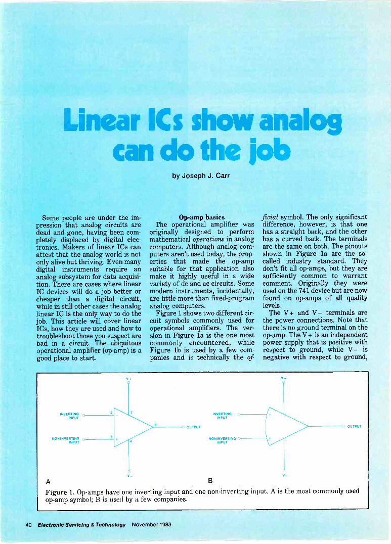
Linear ICs show analogcan do the job
Some people are under the im-pression that analog circuits aredead and gone, having been com-pletely displaced by digital elec-tronics. Makers of linear ICs canattest that the analog world is notonly alive but thriving. Even manydigital instruments require ananalog subsystem for data acquisi-tion. There are cases where linearIC devices will do a job better orcheaper than a digital circuit,while in still other cases the analoglinear IC is the only way to do thejob. This article will cover linearICs, how they are used and how totroubleshoot those you suspect arebad in a circuit. The ubiquitousoperational amplifier (op -amp) is agood place to start.
by Joseph J. Carr
Op -amp basicsThe operational amplifier was
originally designed to performmathematical operations in analogcomputers. Although analog com-puters aren't used today, the prop-erties that made the op -ampsuitable for that application alsomake it highly useful in a widevariety of do and ac circuits. Somemodern instruments, incidentally,are little more than fixed -programanalog computers.
Figure 1 shows two different cir-cuit symbols commonly used foroperational amplifiers. The ver-sion in Figure la is the one mostcommonly encountered, whileFigure lb is used by a few com-panies and is technically the of-
ficial symbol. The only significantdifference, however, is that onehas a straight back, and the otherhas a curved back. The terminalsare the same on both. The pinoutsshown in Figure la are the so-called industry standard. Theydon't fit all op -amps,sufficiently common to warrantcomment. Originally they wereused on the 741 device but are nowfound on op -amps of all qualitylevels.
The V + and V - terminals arethe power connections. Note thatthere is no ground terminal on theop -amp. The V+ is an independentpower supply that is positive withrespect to ground, while V - isnegative with respect to ground,
INVERTINGINPUT
NON INVERTII,INPU!
A
OUTPUT
INVERTINGINPUT
NON INVERTINGINPUT
Bv_
OUTPUT
Figure 1. Op -amps have one inverting input and one non -inverting input. A is the most commonly usedop -amp symbol; B is used by a few companies.
40 Electronic Servicing & Technology November 1983

0.l. F
C24 7,F
- COMMON(GROUND,
C4O.1,F
Figure 2. The power supplyused for an op -amp must bebipolar.
even though no separate groundconnection exists on the op -amp.
The output terminal is self-explanatory. The output signal willswing positive or negative be-tween certain limits less than V -and V+.
The inputs on almost all op -ampsconsist of a pair of differential in-puts. In theory, only the invertinginput is needed, but all commonop -amps also have the noninvert-ing input.
The difference between the twoinputs is a matter of phase. The in-verting input produces an outputsignal that is 180° out of phasewith the input signal. In otherwords, a positive voltage applied tothe inverting input produces anegative output voltage (the in-verting input is marked with aminus sign). The noninverting in-put, which is marked with a plussign, produces an output that is inphase with the input signal. Apositive voltage applied to the non -inverting input will produce apositive output voltage.
Since the op -amp output mayhave to swing either positive ornegative, a bipolar do power sup-ply is needed. Figure 2 shows atypical power supply for an op -ampcircuit. Although batteries areshown here, in most cases elec-tronic power supplies will be used.Note that there are two separate
Maybe We're To DiscreteAbout Our Discrete Products
Diode SpecialsIn Los of 100
1N4148 $3.60/100 1N4004 $3.60,1001N4001 3.00/100 1N4005 4.00/1001N4002 3.25/100 1N4006 4.50/1001N4003 3.40/100 1N4007 5.50100
Transistor SpecialsPN2222A $8.00'100 2N3906 $12.00/100PN2907A 8.00;100 2N3055 .65 ea.2N3904 12.00/100
Carbon Film ResistorsWatt 5`o Tolerance
Now Only $1.50 100All 5 Vdlups Available
Specializing in:
Resistors \TransistorsDiodesSCRsFull Wave Bridges
STOCKEDIN
DEPTH
And the Old and Exotic!
Call Liz and askabout her parts today!
We also purchase excess inventories.Call Martha about your parts today!
"Have You Kissed Your Computer Lately"
Components Express, Inc.1380 E. Edinger Santa Ana, Calif. 92705 714/558-3972
TWX 910-595-1565 ADVACON SNA . International Orders WelcomeTerms of Sale: Cash, Checks, Credit Cards, M.O.. C.O.D. FOB Santa Ana.
Calif. residents add 6% sales tax.
Circle (16) on Reply Card
SELL IBELTSPROFIT AT A
+Q
PRBTHE
SYSTEM
EXCLUSIVE' roof back into selling
IT'S EXCL stem puts the P stock numberrighted system the PRB find it
projector'RB s copyrightedbaits. Because belt and
recd you want. Measure and cross-references.
instantly.
for and s the belt y ces aa,;tua ly describe.
time-consumingreferences
instantly.without time c
A ORDER rot just for belts,A B. Ask ht W you car
can geeswealth of valuable 1 free from PR
onenis, too -Technlcían's Reference
Librarybut for other come
get the PRBneed to make t ie
and theréfere nces You
call collect:products -- 1-g00-558'9572For profrteble P call PRB- I In Canada5003
morele produ ts
Number:TLXUSA 1-613-225
evenn.
Business151
14594411 PRB
In Wiscons1-g00 242-8553
1-414-473-2151414 473PROJECTOR RECORDER BELT ',
200 Clay Street pWhitewater, WI 53190 L t N E
Circle (17) on Reply Card
November 198'3 Electronic Servicing & Technology 41

power supplies: V + and V - . TheV + supply is positive with respectto common, while V - is negativewith respect to common. Thepower -supply common is also usedas the signal common, and mayalso be the ground (chassis) con-nection.
The capacitors shown in Figure2 are not always used, but areneeded in many cases for power -supply decoupling. The capacitorsare always good practice and areespecially needed in multi -stagecascade circuits, when high fre-quency (uncompensated) op -ampsare used, or where the power sup-ply lines may be noisy.
There are two capacitors on eachline in Figure 2. The high -valuetype is used for low frequencies,while the low -value one is for highfrequencies. The low -valuecapacitor should be mounted asclose to the body of the op -amp aspossible. If multiple op -amps areused, a separate pair of 0.11iFcapacitors is needed for each op -amp.
The one case where thecapacitors are not always used ison frequency -compensated (uncon-ditionally stable) devices such asthe 741. Those types of op -ampstrade off frequency response infavor of stability, so they will onlyoperate properly to 8 or 10kHz.
Ideal op -ampsAn ideal op -amp would exhibit
the following properties: zero noise contribution infinite frequency response infinite open -loop gain zero output impedance infinite input impedance differential inputs "stick
together"The first two ideal properties are
never approached, but are thrownin for benefit of the purists whowould insist, correctly, that suchfactors affect performance.
The third property tells us thatthere is no limit to gain. In real
devices, open -loop voltage gains(AVOL) range from 200,000 to morethan 1,000,000. An implication ofthis condition is that closed -loopgain is controlled totally by thefeedback network.
Zero output impedance (Z = 0)means the output will function asan ideal voltage source. Realdevices usually have Z values ofless than 10012.
If infinite input impedance couldbe achieved, neither input wouldeither sink or source current. Realdevices have Z. value of 1M( to101212, and so will be consideredideal in most cases.
The final condition requiressome explanation. The differentialinputs must be treated mathe-matically as if they were at thesame potential. If a voltage is ap-plied to the noninverting input, forexample, the same potential will befound on the inverting input. Thisis not just some theoretician's con-cept, but can actually be measuredwith a voltmeter. The property isthe most frequently used in oursimplified circuit analysis.
Inverting followersFigure 3 shows the op -amp con-
figuration called the invertingfollower. The noninverting input is
grounded and so is at zero poten-tial. The signal is applied to the in-put resistor, R,.
Because of Kirchoffs CurrentLaw (KCL), we know in Figure 3that I2 = I1 (the ideal op -ampdoes not draw current). We alsoknow from Ohm's law that
L
=and
I2 = Vo/R,
KCL tells us that these equationsare equal:
V,,/R, = - V,,,/R,
The transfer function of a circuitis the ratio of the input voltage tothe input voltage (Voy,/V,,,), and iscalled the gain (A,). Solving forthis ratio yields:
- V,/V, = R,/R,or
- A = R,/R,
These equations tell us that thegain is set only by the ratio of R2 toR1. The minus sign indicates thatphase reversal takes place.
An exampleSuppose we need a gain of -100,
and an input impedance of 10K.
Figure 3. The gain of the op -amp inverting follower circuit is set bythe ratio R2/R,.
42 Electronic Servicing & Technology November 1983
WE HAVE A LOTTO BRAG ABOUT ATORA ELECTRONICS
ONE HOURSHIPPINGOthercompaniesbrag about 24 -hourshipping, but we at ORAElectronics have the bestshipping time in the industry.ONE HOUR - that means thatyou can have that importantpart in your hands as early asthe next day.
HIGHIN -STOCKRATIOORA Electronicshas the highest "in stock" ratioin the industry (95%). Theaverage stocking ratio in thebusiness is 75%. That meansless back orders or "out ofstock" items when you orderfrom us!
BETTERSERVICENobody offers better servicethan ORA Electronics - thatincludes packing, order handling,customer service and qualitycontrol. Our employees arehighly trained and experiencedto better serve you.
LOWERPRICESOther companieslower the price on someitems and advertise themheavily. We at ORA Electronicshave a lower overall price-andyes, you'll like OUR total better!
01-
FREE
SHIPPINGOnly ORAElectronics offers free shippingfor prepaid orders (in thecontinental U.S.A.). For COD,charge and open account orders,we charge only actual shippingcosts, no handling chargeswhatsoever!
TWOYEARWARRANTYAll ORA Electronics' semi-conductors and many otherproducts are guaranteed for twofull years. ORA Electronicshas the longest warranty inthe industry because we knowwhat we sell: prime gradeparts, and they are testedfor quality.
ORIGINAL 40111.PARTSORA Electronics offers you onlyoriginal semiconductors, no"replacements" or "substitutes"or "almost the same" parts.Some other companies re -labeltheir parts. When you orderfrom us, you can be sure thatevery semiconductor you buyis a prime grade, ORIGINAL,tested part.
POPULARCATALOGORA Electronics'catalog is the most copied catalogin the industry. It's the easiestto follow, the prices are notconfusing, and a comprehensiveindex is included. Send foryour free copy today!
Call toll free: (800) 423-5336.Calif. toll free: (800) 382-3663.Non -order info: (213) 701-5850.Local: (213) 701-5848.
ORAELECTRONICSA MASON Of ALLIANCE REiARCN CORPORAON
"OUR SERVICE MAKES THE DIFFERENCE"
18215 PARTHENIA ST.. NORTHRIDGE, CA 91325
Circle (36) on Reply Card
November 1983 Electronic Servicing & Technology 43

Rearranging the equation for A,will allow us to find R2 that willyield a gain of -100.
R2 = - AR,R2 = -(- 100i ( l OK)R2 = 1000K = 1M9,
In the example above, we usedthe value of R, as the amplifier in-put impedance. This is truebecause point A is essentially atground potential due to thegrounding of the noninverting in-put. Even though point A ofFigure 3 is not actually grounded,it behaves as if it were grounded.This situation is called a virtualground.
A problem with the invertingfollower circuit is that the max-imum input impedance is limited tothe value of R,. In some practicalcircuits, this value can be some-what low. A solution to the prob-lem is the noninverting followercircuit.
Noninverting followersThe noninverting follower cir-
cuits of Figure 4 apply the signalto the noninverting input of theoperational amplifier. There aretwo configurations: the unity gain(4a) and with gain (4b).
The unity -gain noninvertingfollower of Figure 4a has a voltagegain of one because it uses 100%negative feedback. Uses of this cir-cuit include buffering with neitherloss of voltage amplitude norchange of phase, and impedancetransformation made possiblebecause of the high input im-pedance and low output im-pedance.
Because Vo,,, = V;,,, and the out-put impedance is very low, wemust conclude that the unity -gainnoninverting follower does offerpower gain, even though voltagegain is unity.
The circuit in Figure 4b is anoninverting follower with gain.Using an analysis similar to that
used above for the inverting case,but taking into account that pointA is at a potential equal to V;,,rather than ground, we arrive atthe following gain equation:
Av = R2/R, + 1
The gain version of the circuitcan be used for exactly the same
applications as the unity -gain ver-sion, but with voltage gain as wellas power gain.
Op -amp problemsPractical op -amps do not match
the idealized version. One majorproblem is output offset voltages.This term means that the outputvoltage will be nonzero at a time
A
VI
B
R1I,
11 = 11
(Vout - Vin)/R2= VInIR1
Vout -Vin = R2 Vin/R1
R2
Vo
Vout = R2 Vin/R1 + Vin -
Vout = Vin (R2/R1 + 1)
Av = VoutNIn = R2/R1 +1
Vo
Figure 4. The non -inverting follower op -amp circuit may be usedas a buffer or impedance matching device by making the feedbackresistor equal to zero (A). If the circuit is connected as in B, gain wilbe Ay= R2/R, + 1
44 Electronic Servicing & Technology November 1983

when it should be zero. For exam-ple, if V, = 0, then V,., should alsobe zero. In many cases, however, itwill not be zero.
There are several causes of out-put offset voltages; among themare the input bias currents. Ifbipolar transistors are used in theinput stage, their bias currents willbe available at the (-) and (+) in-put terminals. In that case, the in-put impedance is not infinite.Figure 5 shows a simple methodfor reducing the effect of this cur-rent. The output offset is causedby current from the (-) input flow-ing in R, and R2, creating an inputoffset voltage that is amplified bythe gain. If we force the bias cur-rent from the (+) input to flow inthe same resistance, it will pro-duce an equal but opposite offsetvoltage, and the two cancel eachother. The net result is zero.Resistor R, in Figure 5 is called acompensation resistor and servesthis purpose. Resistor R, has avalue equal to the parallel com-bination of R, and R2.
The method of Figure 5 solvesonly one form of output offset volt-age problems. Those of Figure 6,however, solve all forms of normaloutput offset voltage problems, in-cluding that caused by input biascurrents.
Figure 6a shows a circuit that isused when the op -amp is equippedwith a pair of offset null terminals(not all so equipped). A poten-tiometer is connected between theoffset nut terminals, and its wiperis connected to the V - power sup-ply terminal. This potentiometer isadjusted to produce V,,,, = 0 whenthe V,0 input is shorted to ground(or common). Alternatively, thepotentiometer is sometimes ad-justed for V,y, = 0 when the (- )and (+) inputs are shortedtogether.
A more universal scheme isshown in Figure 6b. Here we nullthe natural output offset by usingthe potentiometer to introduce acounter -offset of a magnitude andpolarity to completely cancel theoffset voltage. Adjustment of the
R1
'bias
V1 = V2 IfR3 = R1 parallel with R2
Iblas
R3
Al
R2
Vr
Figure 5. If bipolar transistors are used in the input stage of theop -amp, their bias currents will cause an output offset voltage. Ad-dition of R3, equal to the parallel combination of R1 and R, will com-pensate for this offset.
New!80MHz
B&K-PRECISIONmulti -function
counterdoes it all...
FREQUENCY
PERIOD
TOTALIZE
B&K-PRECISIONModel 1805 $290
Now you can have one counter that han-dles most every need, at an affordableprice. Conservatively rated at 80MHz,the 1805 is not just another frequencycounter. In addition to measuring fre-quency, it also measures period andtotalizes, so it's ideal for many industrialand service industry applications. Tobest resolve your measurement ques-tions, the 1805 displays input signals to afull eight digits on a bright LED display.Resolution is up to 0.1Hz.
For accurate measurement of low fre-quency signals when high -frequencynoise may be present, a low pass inputfilter may be selected. Other featuresinclude a switchable input attenuatorand a stable timebase.
Further separating the 1805 from othercounters in its price class is the displayhold feature. A touch of a button freezesany displayed reading and holds it-even after the input signal has beenremoved.
The new B&K-PRECISION Model 1805is available for immediate delivery atyour local distributor. For the name ofyour nearest distributor or foradditional information, call:
:« PRECISIONDYNASCANCORPORATION
6460 West Cortland StreetChicago, Illinois 60635.312/889-9087
international Sales. 6450 W Cortland St.. Ch,eaoo. IL 50635Canadian Sales. Atlas Electronics. Ontario
South and Central American Sales.Einwre E.00rters. FlaInv,tw. NY 1,803
November '
Circle (18) on Reply Card
983 Electronic Servicing & Technology 45

A B
R3
Figure 6. Some op -amps are provided with a set of offset -null terminals to provide for output -offset com-pensation.
A
C
A B
B
V
Cl
R1 R2
- 1
D
Figure 7. Op -amps will oscillate under some conditions. It may be necessary to limit the frequency of theop -amp by adding external components in order to preclude oscillation.
46 Electronic Servicing & Technology November 1983

potentiometer is accomplished bysetting the input voltage to zero(shorting the input(s) to ground).The potentiometer is then adjustedfor an output voltage of zero.
Frequency compensationSome operational amplifiers
have such limited frequencyresponse that they are said to beunconditionally stable. A 741device, for example, operates onlyto a few kilohertz. Others, how-ever, have much wider band-widths, and under some circum-stances will oscillate at some
natural frequency. For theseamplifiers, other means must befound. Figure 7 shows severalmethods for reducing the frequen-cy response.
Figure 7a shows the use of acapacitor across a pair of frequen-cy compensation terminals (whichare also sometimes the do offsetterminals. Typical values for thecapacitor are 10pF to 1000pF.Figure 7b shows a feed -forwardcapacitor between a compensationterminal and the output terminal.In Figure 7c we have an RC net-work between the compensation
terminal and ground. The finalmethod, in Figure 7d, shows acapacitor shunting the feedbackresistor. At low frequencies,where X, is much higher than Ref
the gain is essentially R2/R,, or(R2/R, + 1) in noninverting follow-ers. At higher frequencies, thegain falls off at a rate of - 6dB/oc-tave. The frequency at which thegain starts falling off is measuredfrom the - 3dB frequency as de-fined by:
f = 1/27rR2C1
$
$
$$
$ 130 $
$ 154 $
$ JAPANESE TYPES (MIN. 5 PC. EACH)$ 2SC867A 2.75 HA1366W 1.85 STK0029 3.80 $$ 2SC1114 3.25 HA1377A 2.90 STK0080 9.99 $$ 2SC1308K 1.95 LA4102 1.25 TA7205AP 1.50 $AN214Q 1.45 M51515BL 2.95 TA7208P 1.85c'"
AN239A 4.60 STK433 3.95 TA7222AP 1.95 $$ BA532 . 1.80 STK435 3.95 UPC1181H 125 $$ GH3F .... .89 STK437 6.25 UPC1182H 1.25 $$ HA1342A 2.30 STK439 6.50 UPC1185H 2.99 $$ COO ORDERS WELCOME ($25 MIN. ORDER)
$ FoDIGITROrComplete
NonentELECITRONIC
Call or Write
$ 110 HILLSIDE AVENUE, SPRINGFIELD, N.J. 07081 $$ Toll Free: 800-526-4928 In NJ: 201-379-9016 $$ ECG IS A TRADE MARK OF PHILIPS ECG.
DIGITRON ELECTRONIC IS NOT ASSOCIATED IN ANY WAY WITH PHILIPS ECG.
$$ $$$$$$$$$$$$$$$$$$$$$$$$$$$$$$$$$ $Circle (19) on Reply Card
$$$$$$$$$$$$$$$$$$$$$$$$$$$$$$$$$$$$ TECHNICIANS & SERVICEMEN $$ COMPONENTS FOR YOUR MAINTENANCE 8 REPAIR WORK $$ SPECIAL: OUR LOW LOW PRICES $$ REPLACEMENT FOR ECG© TYPES $$ TYPE NO YOUR COST TYPE NO. MilCOST$ 85 FOUR for .99 125 SEVEN for .99$ 102A. .. THREE for .99 159AP.... FOUR for .99$ 123A FIVE for .99 177 EIGHT for .99$ 123AP SIX for .99 199 FIVE for .99
$ SUPER SPECIAL (MIN. 5 PC EACH)$ TYPE NO TOOL COST TYPE NO TOOI COST TYPE NO. TOO COST
$ 124 .85 165 2 25 375 90128 45 171 .65 506 55$ 129 45 184 45 500A 8.95
80 185 45 523 9.9540 238 2 25 526A.... 10.2040 276 6 95 529 13.7560 291 95 712 1.25
OPTIMA ELECTRONICSTO ORDER CALL TOLL FREE 1-800-327-0224
G.E., SYLVANIA, ZENITH, RCA,75% OFF LIST NEWBOXED 3A3 5 FOR $15.75 6LF6 5 FOR $34.44 6MJ6 5 FOR $34.88 O 6LB6 5 FOR $31.50 6JE6 5 FOR $32.75 O 6CJ3 5 FOR $14.69 3DJ3 5 FOR $17.44 O 6JS6 5 FOR $29.00 6GH8 5 FOR $12.44 6BL8 5 FOR $12.25
All Tubes Not Advertised, Write in at 75% Off List.Sleeves Only. Singles 72% Off List
HORIZONTAL OUTPUT TRANSISTORS REPLACEMENT TRIPLERS$1.95 ea. Min. 10, 2 yr. Warranty 500A ..$11.95 526A . $14.95
RKS1172B O RKS238 522 ...$11.95 0 529 ...$15.50 RKS1308K RKS165 523 ...$13.95 0 539 ...$15.75
TRANSISTORS & I.C.'e MIN. 10, CAN MIXT.V. 0's Pop. I.C. M s STEREO N's
2SC1114 ..$3.75 0 712 $1.50 DM133 $5.95MN8303 ... $3.95 0 713 $1.50 DA101 $5.752SC1034 ..$5.95 0 714 $1.50 HA1377A $3.252SC867A . $3.50 0 731 $1.50 HA1388 $5.252SD870 ...$4.75 0 790 $1.50 HA1396 $5.502SD871 ...$5.50 0 791 $1.85 HA1398 $4.95AN5210 ...$6.50 0 793 $1.95 UPC1181 $1.25AN5310 ...$3.95 0 819 $2.25 UPC1182 $1.25AN5320 ...$3.25 0 820 $2.25 UPC1185H ....$3.50AN5435 ... $2.95 821 $2.00 UPC1367 $3.25LM1818 ...$3.25 0 822 $2.75 UPC1368H2 ...$3.95
GENERAL Exact Rep. for SG613 5 for $35.00 HI DIV-3 (800-616 equiv.) focus block div. 10 for $35.00 6 ft. Cheater Cords SPT2 10 for $ 7.95
(Heavy Duty - UL App. 7 Amp. 125V. P & NP) Solder Wick 10 for $6.95
BSR Changers $32.95 Replacement Tone Arms (mono & stereo) 5 for $6.00 Speaker Wire-50ft. 24 gauge 5 for $5.00 Fiberglass Align Tool Set (5 pcs) 5 for $4.00 2.5 Amps 1000 PIV Rectifiers 100 for $8.95
Quantity Prices AvailableLetters of credit and all checks placed on deposit with Bank of Hallendale,FL. VISA & Master Charge accepted. Min. order $75. FOB Dania, FL.Catalog $3, refundable upon order.
SEND CHECK OR MONEY ORDER TO:
OPTIMA ELECTRONICS2022 Tigertail Blvd., Dania, FL 33004
Phone (305) 920.3550 TOLL FREE: 1.800.327.0224
Circle (20) on Reply Card
November 1983 Electronic Servicing & Technology 47

Test
your electronic
knowledgeBy Sam Wilson, ISCET test director
These questions are similar toquestions used on the various CETtests. All questions on the actualCET test are multiple choice, anda grade of 75% or better is re-quired for passing. This month'squestions are all about power sup-ply. (Answers on page 57)
1. Which of the following is trueregarding the rectifier diodesin Figure 1?A. The diode -resistor combi-
nation doesn't make sense.B. The combination assures
equal forward voltagesacross the resistors.
C. The combination assuresequal reverse voltagesacross the resistors.
D. The PIV of the combina-tion is the same as thelowest PIV rating of thethree diodes.
E. The PIV rating of the com-bination is the same asthe highest PIV rating ofthe three diodes.
4.
2. Which of the following is thepurpose of the resistor in therectifier diode -resistor combi-nation of Figure 2?A. Limit the forward current 5.
through the diodes.B. Assure that both diodes
will conduct.3. Which of the following is true
regarding the rectifier diodesin Figure 2?A. The diode -resistor combi-
nation doesn't make sense.
B. The combination assuresequal forward voltagesacross the resistors.
C. The combination assuresequal reverse voltagesacross the resistors.
D. The PIV of the combina-tion is the same as thelowest PIV rating of thetwo diodes.
E. The PIV rating of the com-bination is the same as thehighest PIV rating of thetwo diodes.
The circuit of Figure 3 isA. a discriminator.B. a ratio detector.C. a full wave rectifier.D. a voltage doubler.E. two half -wave rectifiers.The broken line between theprimary and secondary wind-ings in Figure 3 representsA. a self -resonating
transformer.B. a saturable reactor.C. an auto transformer.D. Faraday shield.E. a phase shifter.
48 Electronic Servicing & Technology November 1983

6. The purpose of the 4.79resistor in Figure 4 isA. to limit the output voltage
to a given value.B. to improve the supply
regulation.C. to protect the diode.D. to protect the output load
resistance.E. None of these choices is
correct.7. The output voltage of the
supply in Figure 4 should beaboutA. 140V.B. 100V.
8. In the circuit of Figure 4you will find the audio poweramplifier connected to whichpoint?A. aB. b
9. All of the diodes in the circuitof Figure 5 are silicon types.Which of the following is trueregarding this circuit?A. The output is short cir-
cuited.B. The diodes are connected
in the reverse direction.
ty onwatta ohabte
Iwo -YeartOWest"désotders
lhet A P E
features
Sdy
1tiePrmP bXt ¡stf ye-5'25
May
bpG boards Mode 550¡n9tanduse
t otder extractor, mo11 u¡et operanon nOn C1o99
componentsOW-anon-Isolated
t100 handPe ontrols r Wnte
v;brat`On atr EX-
ted byPan our shop Gaon E4atp Qe3?.
N¡th shOp re re9°ta 525 ¡n y producU 516-65
tVoPne d thethe tieta5. AMto`daNY
11763
today tor 2 pec°n¡cAve.,
Corp.,14'2.
tWDEPEND
-ON
C.
D.
E.
The diode current must beequal to the load current.In order for the circuit towork properly, VIN mustbe at least 25V.The output voltage isabout 2.1V.
10. The circuit in Figure 6 isA. a short circuit across the
secondary.a bridge rectifier.an open circuit.a preregulating circuitand full -wave rectifier.ok if all of the diodesare reversed.
B.C.D.
E.
FINALLY. COMPUTERS AS ANEW TOOL FOR T.V. REPAIR.
Primefax puts computer -assisted repair capabi ity in your shop today.
Primefax drastically reduces thenumber of sets requiring extensivetrouble -shooting procedures.Through the use of today's tech-nology. Primefax maintains-in acentral computer-a database ofproblem -solving solutions fortelevision set malfunctions.Primefax is a compilation of themost current, applicable technicalinformation acquired from hun-dreds of valuable sources ... andupdated daily.
With a Primefax Computer Terminalinstalled in your shop, you can doyour job more quickly and more
accurately. You have more satisfiedcustomers, and your profits areincreased substantially.
Reduced call backs faster turn-around reduced chance ofrepeated failure . more thoroughservice and complete repair atreasonable cost.
The more Primefax is used, themore profit you realize.
CALL US OR WRITE. No matter howyou compute it, Primefax meansprofit for you. It's worth lookinginto.
In Texas. call (512) 344-5999. Out of Texas, call 800-531-5953
Primefacugg
4825 Fredericksburg Road San Antonio, Texas 78229
Circle (21) on Reply Card Circle (22) on Reply Card
November 1983 Electronic Servicing & Technology 49

Understandingdecibels and
time constantsThe two previous articles in this
series (August and OctoberES&T) have covered the inventionof logarithms and their relation-ship with epsilon (e). In this article,we will show how epsilon is relatedto the charge of a capacitor.
Why study math?Mathematics is a shorthand
method of expressing relationshipsin electrical and electronic circuits.Technicians should think ofmathematics as being an aid(rather than a hindrance) toanalyzing electronic circuits andsystems. Unfortunately there is somuch new technology to belearned that the importance ofbasic mathematics relationships isoften underestimated.
I have heard technicians boastthat they have worked many yearsin electronics and never even usedOhm's Law.
Suppose a technician measuresthe voltage across a resistor andfinds that voltage is too low ac-cording to the manufacturer'sspecifications. He immediatelyknows that the current orresistance (or both) is too low. Heknows that because he knowsOhm's Law. He knows that thevoltage across a resistor dependsdirectly upon the current andresistance. In other words, heknows that V = I x R.
Every time a student learns anequation, he is learning a short-hand method of remembering rela-tionships in circuits. Imagine try -
By Sam Wilson, ISCET test director
SW
V
Figure 1.
ing to learn about electronics bydealing with Ohm's Law stated,"The amount of voltage dropacross a resistor is dependent uponthe amount of current flowingthrough that resistor, and it is alsodirectly dependent upon theamount of resistance of thatresistor."
Can you imagine having to learn20 or 30 laws similar to that beforeyou could begin to understandbasic electric circuits? Fortunatelyyou don't have to. The simple equa-tion V = IR tells it all.
Time constantsHow was the time constant
equation (T = RC) obtained? Con-sider the circuit of Figure 1. Thecapacitor is discharged. It willstart to charge the instant theswitch is closed. The mathematicalequation for the voltage across thecapacitor (ve) at any instant of timeafter the switch is closed (t) is:
ye= (1- 1 ) VetrRC
Where V is the applied voltage, Rand C are the resistance andcapacitance in ohms and faradsrespectively, and e is epsilon(2.71828).
50 Electronic Servicing & Technology November 1983

A special case occurs when t is capacitor is discharged to start.)made equal to R x C.
t = RC= 1RC RC
For t = RC, the equation becomes:
vc+ (1- 1 )VedRC
_ (1- 1 )Ve'
_ (1- 1 )V2.71828
v,= 0.632V, or, v,=63.2% V
This equation shows that thevoltage across the capacitor is63.2% of the applied voltage whent = RC. That is the reason that thevoltage on the capacitor after onetime constant equals 63.2% of the,applied voltage.
An important thing to note fromthis discussion is that e is a factorin calculating the growth ofvoltage across p chargingcapacitor. This peculiar number(2.71828) is related to many fieldsother than electronics and biology.
The time constant equation (T,=R x C) is useful when you want tofind how long it takes a capacitorto charge to 63.2% of the appliedvoltage. But how do you find thevoltage across the capacitor forsome other value of time? If youhave a calculator, it is a simplematter to use the equation for v,. Ifyou do not have a calculator,follow the step-by-step procedureto increase your insight into thetime constant.
Sample problemIn the circuit of Figure 1, the
following values apply: V= 5V,R= 1Mt1 and C =1µf.
What is the value of v, 0.5s afterthe switch is closed? (For this typeof problem, always assume the
SolutionThe time (t) is 0.5s, and the value
ofRxCis:
RxC = 1x10°x1x10-°
orRxC = is
The equation can now be solved:
v,= (1- 1)V
e ./RC
= (1- 1 )x5eo.aii
V = 1.97V
So, in 0.5s the voltage across thecapacitor has increased to slightlyless than 2V.
The equation for v, can be usedfor many practical problems.However, in technicians' books,T, = R x C is often given as the on-ly time constant equation. And forfull charge of the capacitor, theequation is given as T, = 5 x R x C.
Is the capacitor really charged tothe full supply voltage in five timeconstants? Not quite. If you use t= 5 in the equation for v,, you willfind that the voltage across thecapacitor is 99.3% of the supplyvoltage at the end of five time con-stants.
So when does the capacitor ac-tually become fully charged?Never. You can raise e to any largenumber and if your calculator canwork with that number, you willfind that the capacitor is not quitecharged to the full supply voltage.
The value of five time constantsfor full charge was chosenbecause, for all practical con-siderations, the capacitor is fullycharged after that amount of time.
Arriving at the equationsHow did they arrive at the equa-
tion for decibels, time constantsand Ohm's Law? The curve for theresponse of the human ear toloudness and the curve that shows
the voltage across a capacitor dur-ing charge are both logarithmic.
If you were an early ex-perimenter working on hearingmeasurement and graphed yourresults, you would soon come tothe conclusion that the generalshape of the curve is the same forall people with normal hearing. Ifyou had a basic math background,you would recognize that you aredealing with a logarithmicresponse, so you would write anequation that involved logs for thehearing response.
The process of writing an equa-tion from a curve is called curve fit-ting. This is not to play down thevaluable contribution of the peoplewho did this important work. But,technicians are sometimes puzzledabout where certain equationscome from.
You could not derive the equa-tion for decibels without first mak-ing a lot of measurements to seewhat type of response you aredealing with. Equations that arederived this way from data arecalled empirical equations.
The equation for V, was derivedthe same way. Data was taken andcurves were drawn, then the equa-tion that fit that curve was writ-ten. Therefore, V, is an empiricalequation.
It is interesting to note thatOhm's Law (V = IR) was derivedempirically. Georg Ohm lived inthe shadow of his brother, whowas a famous biologist in Europe.
Ohm studied the relationshipbetween voltage and current, thenwrote an equation that related thetwo. His first published paper gavean equation that was not correct.Fortunately, he reworked theequation and soon published it inthe form we use today.
So far in this series we havetalked about the concept ofdecibels and time constants. In afuture issue, we will continue withthe time constant equations andthen give examples of practicalproblems that can be solved withthe equations discussedup to this point.
November 1983 Electronic Servicing & Technology 51

Troubleshootingsymmetrical
output circuitsThe most common type of audio -
output circuit uses two transistorsin what is commonly called a push-pull or complementary arrange-ment. There are many specific ex-amples of circuits of this type, butfortunately only three basic varia-tions on the theme. These are thepush-pull transformer -coupledtype, the true output -transformer -less (OTL) type and the most com-mon of the three, the quasi -complementary type.
The easiest to understand is thegarden-variety transformer -drivenoutput stage (Figure 1). You willcome across this circuit or its closecousins in all tube circuits, oldertransistorized products and less -expensive products. Because a ma-jority of the products in the servicemarket now are solid state, we'lljust look at transistor circuits, butthe exact same analysis applies totube circuits.
The output transformer is drivenby both Ql and Q2. The signal in-verter make the top and bottomsignals fed to each device a mirrorimage of each other because theyare 180° out of phase. Each deviceis biased into cut-off either half ofthe time (pure class B operation)or slightly less than half of thetime (class AB operation). Thisoverlap in conduction is created inorder to eliminate crossover distor-tion, which can occur if one deviceturns on as the other turns off.This can be easily observed on thescope as a "notch" appearing as thewaveform crosses the zero -conduc-tion point.
When either transistor con-ducts, it induces a voltage acrossthe entire transformer primary,which is then coupled to the trans -
By Bud Izen, CET/CSM
former secondary and thereforeappears across the speaker. De-pending on the design choice madeby the manufacturer, the out -of -phase signals used to drive eachdevice may be furnished by asingle inverter stage, which af-fects only one of the output devices(the bias makes sure when eachone starts to conduct), or may befed by an input transformer. Sucha transformer provides twosignals, each 180° out of phasewith the other (Figure 2).
Transformer couplingThe disadvantages of using
transformers are phase distortiondue to the reactance of the trans-former, loss of low -frequencyresponse due to core loss, weightincrease, increased cost and theresulting increase in product size,and energy consumption due totransformer inefficiency. Themain advantage of using trans-formers is ease of design, and alesser advantage is that short cir-cuits in the driver stage areisolated from the output stage andvice versa. For this reason,troubleshooting is fairly straight-forward.
A more complex circuitNeither of the circuits of Figures
1 or 2 are practical enough towork, yet they are not far from be-ing usable. A realistic circuit usinga single transistor as a phase split -ter is shown in Figure 3. Thesignal at the collector of Q1 is 180°out of phase with that on the base,which can be treated as being incommon emitter configuration.The signal at the emitter is inphase with that at the base, and
can be thought about as being incommon -collector, or emitter -follower configuration.
The gain of the Q1 stage is set bythe ratio of R3 divided by R4, andis adjusted so that the signals fromcollector to ground and emitter toground are essentially equal, andopposite in polarity. Ql and Q2 arethen biased into class B or ABoperation by resistors R5 and R6.Capacitors Cl, C2 and C3 arenecessary in order to avoid quies-cent operating point shift. Al-though more parts are required toaccomplish this design than theprevious one, frequency responseis better and the cost is lower.
The complementaryoutput circuit
Figure 4 shows a somewhatmore complicated design that re-quires neither a phase -splitting de-vice nor a transformer. By usingone NPN and one PNP device(each the other's complement),push-pull action occurs withoutany external help. The two tran-sistors are placed in series acrossthe do power supply. Resistors R3and R4 provide fuse protection andsome amount of thermal stability.R1 and R2 provide base currentpaths at the proper time.
Diodes Dl and D2 (often part ofa single unit) provide bias stabilityin the following manner. Undernormal conditions, the two tran-sistor bases are about 1.2V apart.In an NPN device, the base is nor-mally 0.6V more positive than theemitter, while in a PNP device thebase is 0.6V more negative thanthe emitter. Ignoring the smalldrop across R3 and R4, the basesshould measure normally about
52 Electronic Servicing & Technology November 1983

SIGNALINVERTER
Zvcc
Figure 1. A push-pull output driven by a signal inverting stage.
O, output
0, output
Figure 2. A push-pull output driven by a phase -splitting driver transformer.
VCC
Cl
Figure 3. A circuit using a single transistor as a phase splitter.
Figure 4. A basic complementary -symmetry amplifier with ther-mal stabilization.
1.2V apart constantly because theemitters are essentially tiedtogether.
The diodes are mounted verynear the output transistors, oftensecured to them or mounted on thesame heat sink. The temperatureresponse of the diodes is matchedto that of the transistors. As thetemperature of the devices in-creases, causing the transistors toincrease in conduction, the voltageacross the diodes decreases,limiting base current. Therefore,thermal runaway can be con-trolled.
Avoiding a critical errorA word of caution is necessary at
this point. Because the diodes arematched to the output devices, if itis ever necessary to replace thediodes, use only exact replace-ments. Also, if new output devicesare required in circuits like this, itis wise to order the diode unit(s) aswell. In the case of a part numberor type change when the orderedparts are received, this will ensurethat a repair brings the unit backto specs without worry or un-necessary delay. There is nothingmore annoying than to installsubstitute devices with differentnumbers than the original partsand have the unit fail because thetemperature characteristics of thediode are not the same as that ofthe replacement device.
Obviously, the same caution ap-plies when using general sub-stitutes for original parts. Theymay or may not work, even if the
November 1983 Electronic Servicing & Technology 53

Figure 5. The circuit of Figure 4 preced-ed by a class -A voltage amplifier.
manual says they will. In general,you will always be better off re-placing output devices with exactreplacements. The higher thepower of the amplifier, the morelikely this is to be true. If theamplifier is direct -coupled, thiswill be crucial in avoiding disaster.
To illustrate this, the servicemanager of a local branch of achain stereo store told me that oneday a local servicer came in to dropoff an amplifier. The servicer com-plained that the "darn thing justwasn't any good," and was "im-possible to fix." He had replacedvirtually every transistor in theunit with a well-known generalsubstitute device.
Unfortunately, the amplifier wascompletely direct coupled. All ittook was a little bias shift, andevery single substitute device wasdestroyed. Replacement of thetransistors with exact replace-ments and output current adjust-ment was all it took to repair theunit.
The analysis continuesBecause the output of the circuit
in Figure 4 is taken from the emit-ters, no matching transformer isneeded. However, because the de-sign requires that half of the dosupply voltage be dropped acrosseach device, steps must be taken tokeep de out of the speaker. C2 is
vec added to block do from pass-ing through the voice coil, whichotherwise would cause core satura-tion and possible coil burnout.
If you work on a speaker thathas been burned out, don't forgetto suggest to the customer that the
amplifier should bechecked for possibledc presence. Like-wise, it is alwaysnecessary to checkfor presence of ex-cessive de on speaker
lines each time an output circuit isrepaired. Usually a maximum dolevel is given on the schematic orin the adjustment procedures. Iwould suggest that no more than0.025V be present.
Becoming more practicalThe circuit of Figure 4 is still not
quite practical, but is close.Because Ql and Q2 are emitter -followers, the output stage has avoltage gain of slightly less thanone. It is therefore necessary toprovide at least one stage ofvoltage gain before the output.Figure 5 shows the circuit ofFigure 4 redesigned with Q3 addedas a pure class -A voltage amplifier.R3 and Rl couple back negativefeedback to stabilize the gain of Q3by monitoring a rise in voltage at
Rq
.R5
the junction of C3, R6, R7 and R3.The Q3 operating bias is obtainedthrough that same source, whileobtaining collector bias from R5,D2 and Dl. C2 is provided toeliminate any signal voltage feed-back. This circuit is now practicalenough to find application in manysorts of products, but it can berefined further.
Disadvantages ofcoupling capacitors
Coupling capacitors have severalundesirable characteristics. Theycause phase distortion becausethey have more reactance at lowfrequencies than at high frequen-cies. Coupling capacitors that areused to couple the signal from out-put devices to speakers whileblocking de must be very large insize (often thousands of micro -farads) because of the low im-pedance nature of output circuits.In order to avoid pronouncedphase shift and accompanyingvoltage -divider action, thecapacitive reactance should be nomore than 10% of the speaker loadresistance at the lowest operatingfrequency. If such is not the case,loss of bass response is often theresult. Physically large capacitorsare expensive and limit the overallcompactness of the amplifier.
R3
Figure 6. dc -coupled complementary amplifier.
±
54 Electronic Servicing & Technology November 1983

Figure 7. Quasi -complimentary sym-metry.
A solution to the problemsFigure 6 shows the circuit of
Figure 5 modified to eliminate theneed for all coupling capacitors.Instead of using one source of Vcc,the original Vcc is divided into twosupplies, one negative and onepositive. Initial engineering of theoutput transistor biasing will en-sure that the speaker output linewill have essentially 0Vdc onit. Transistors Q4 and Q5 are add-ed as a differential pair. As long asthe speaker line remains at 0Vdc,Q5 essentially does nothing. If thevoltage on the speaker line rises(in either the positive or negativedirection), Q5 will change conduc-tion so as to restore balance. R4serves as a constant currentsource for Q4 and Q5, allowing thisaction to occur.
The voltage on the speaker lineis referred to as the offset voltage.The offset voltage is monitored bythe current flowing through R5.The do levels can then be altered,depending upon the direction ofoffset shift.
Troubleshooting analysisAs an example, let's examine
what would happen if the offsetvoltage increased negatively. Q5would turn on harder, its collectorvoltage would fall, increasing the
drop across R3. The voltage at thebase of Q3 would be less negative,turning on Q3 more and loweringits collector voltage. In turn Qlwould turn on harder and Q2would conduct less, regaining zerooffset. In order to analyze thereverse situation, a positive in-crease in offset voltage, merelychange the words in the aboveanalysis. Change up to down, fall
to rise, less to more, harderto less hard and low-ering to raising. The
final result is the same:restoration of zero offset.
Improving damping factorThe application of a concept
called damping factor is a majorconcern to users and manufac-turers alike. In order for theamplifier to be able to controlspeaker cone movement, the ratioof speaker impedance to amplifieroutput resistance must be fairlyhigh. Elimination of the outputcapacitor improves that ratio asthe capacitive reactance increasesthié output impedance when such acapacitor is used. Because the cir-cuit of Figure 6 accomplishes thistask, you will find its application inmany high -quality amplifiers. Cir-cuits such as these produce damp-ing factors from 20 to 50 andabove.
More power neededUnfortunately, with few excep-
tions, complementary NPN-PNPpairs are hard to match for high -power applications. Above 10W orso, NPN power types become ex-pensive, too. Factors liketemperature coefficient and betadrift become critical in high -powerapplications, and slight discrepan-cies in such characteristics usuallyresult in catastrophic failure.When high power is needed, acomplementary pair is often usedas a driving stage, while two NPNtypes are used to actually providethe power. This type of circuitry iscommonly called quasi -complemen-tary symmetry. Circuits combin-ing the features of both circuits inFigures 6 and 7 are common.
Figure 7 shows a typical, simpli-fied but accurate representation ofsuch an output configuration.When a positive voltage is present-
ed to the base of Q1, increased con-duction takes place in both Ql andQ3. Notice how the collectors of Qland Q3 are tied together and thatthe emitter of Ql feeds the base ofQ3. This is called a Darlington -pairconfiguration. Sometimes manu-facturers provide such a pair in asingle conventional 3 -leadpackage. Watch out for this inmaking substitutions. The netresult is that Ql and Q3 acttogether to simulate a high -powerNPN device.
Similarly Q2 and Q4 are connect-ed to simulate a high -power PNPdevice. When a negative signal ispresented at the base of Q2, itturns on, making the voltage on itscollector less positive and causingQ4 to conduct harder.
In order to stabilize the voltagedrop between the bases of Q1 andQ2, diodes Dl through D3 areused, often integrated into a singlepackage as previously discussed.Three diodes are needed becausethere are now three junctions tostabilize (Q1, Q2 and Q3).Resistors R1 through R5 are usedto provide thermal stability andfuse protection. They are notalways used in such circuits. In allrespects, these types of circuitscan be analyzed just the same wayas the true complementary circuitspreviously discussed.
A final cautionAfter the repair of an output cir-
cuit of an audio amplifier, it isvitally important to make sure thatthe cause of failure is not external.Many times output circuits can beblown by shorted speaker wires,an excessive number of speakersbeing driven by the unit, or bysomething defective in one of thespeakers themselves. Many ser-vicers I know will not warranty anoutput circuit repair unless thecustomer brings in the speakerwire and sometimes even thespeakers themselves. Doing any-thing less is taking a gamble.
It is also entirely possible thatwhen the output stage failed, thespeaker system was simultaneous-ly damaged. Failure to check outthis possibility leaves you opento all kinds of unpleas-ant possibilities.
November 1983 Electronic Servicing & Technology 55

IMIII-~...-.r
Symptoms and cures compiled from field reportsof recurring troubles
Chassis - RCA CTC108PHOTOFACT - 2030-2
U701
LUM CHROMA
+11V
2200 4
TP806
Q702
VERT BLANKER
R710
3900 it
OPEN
R709 R712 A/PULSES
56K (47KI
Symptom -Normal sound, but no rasterCure -Check resistor R712, and replace it if open orincreased in value
1 i Chassis RCA CTC53Ei PHOTOFACT-1201-1 or 1342-2
Chassis - RCA CTC76PHOTOFACT -1468-2 or 1616-1
CR4 CR2
3
FROM T101 +82 5V
CR5 CR3
C103C i_750µFR
\ OPEN
Symptom - Insufficient height at bottom and erraticvertical rollingCure -Check filter capacitor C103C, and replace can ifany section is open
Chassis - RCA CTC111 5PHOTOFACT - 2038-1
+11 4V
Q3
RED
R12
1000 4
L3
27K
R6
R3
22009
12K
2W
+ 211V
CRT RED
CATHODE
PIN 8
SGI 5
SHORTED
Symptom - Bright red screen with retrace; shut -downafter a few secondsCure -Check spark -gap SG1-5 on the kine-drive board,and replace it if shorted
r
r
C6
022µF
C7
0.01µF
R16
1800 it
R18 220K
C12
82pF 120K
R33 1000 4
Q3 R19 180KSYNC SEP
R17 680K
+ 17.5V
Symptom - Erratic horizontal pulling in pictureCure - As a test, replace Q3 sync separator
+ 265V
REPLACE
R45
2
Chassis - RCA CTC97PHOTOFACT-1862-1 or 1931-2
Q15
COLLECTOR
SIR114 1M 12
SERVICE o
BAD CONTACTS -32 2V
Q16
VERT OSC
R103
4
Symptom - Intermittent rolling or loss of heightCure -Check the service/normal switch, and replace it ifcontacts are erratic or leaking to ground
Chassis - RCA CTC109 6PHOTOFACT-1952-1
120 VAC
CR101 CR103
CR104
C105 LI00µF
OPEN
+ 162V
SOURCE
Symptom - Receiver began operating by itself andcannot be switched off, also the picture has an hour-glass shape with ac -hum instabilityCure -Check C105 filter capacitor, and replace it ifopen
ti
56 Electronic Servicing & Technology November 1983
J
i
Answers to quiz(from page 48)
1. C There is no assurancethat the reverse resis-tances of diodes are equaleven though they havethe same type number. Itis possible that a reversevoltage can be excessiveacross one of the diodesif its reverse resistanceis high compared to theother two. The high -resistance resistors inFigure 1 have identicalvalues and they equalizethe reverse voltage drop.
2. B If one diode has a for-ward voltage of 0.7V andthe other has a forwardvoltage of 0.8V, they can-not be connected directlyin parallel. The reason isthat if the 0.7V diodestarts to conduct, theother one will never haveenough voltage across itto start it into conduc-tion. The resistors assurethat when one diodestarts to conduct, thevoltage across thatbranch will be highenough to start the otherdiode.
3. D4. E Discriminator and ratio
detectors require tunedtransformers.
5. D The purpose of this shield
is to prevent electrostaticcoupling between theprimary and secondary.
6. C In a few cases thisresistor has been used fortwo purposes. It protectsthe diode from the surgecurrent that occurs whenthe capacitors are firstcharged. At the sametime it may be used as afuse to protect the supplyfrom a constant over-load.
7. A The output capacitorcharges to the peakvoltage of the inputminus the drops acrossthe filter, diode andsurge limiter.
8. A Power amplifiers do notrequire a highly filtereddo voltage. By connect-ing the power amplifierto point a, it is notnecessary to have a highcurrent flowing throughthe filter resistor.
9. E With about 0.7V acrosseach diode, the outputvoltage will be about2.1V.
10. A The only limit to thesecondary current oneach half cycle is the for-ward voltage dropsacross the diodes.
ARTICLEREPRINTSInterested in reprints of an article out of this or anotherissue? Reprints of articles about your company or theindustry can be valuable sales and marketing tools. Forinformation, call or write Robyn Kahn, IntertecPublishing Corp., P.O. Box 12901, Overland Park, Kansas66212; (913) 888-4664.
EL
Professionals,Here are your Black Books
Over 1500 Manufacturers 25,000 Products 81/2" x 1 1 " Catalog Format Perfect Binding for Durabil ty Pictures, Descriptions, Features,
Options, Specifications, Prices Up-to-date as of August 1983
Telephone Orders Accepted WithPurchase Order or Credit Card
Call Toll Free (800) 255-6038
HIGH TECH MARKETING CO.P.O. Box 2056Shawnee Mission, KS 66201
Exclusive Distributors for BILL DANIELS CO., INC
Circle (23) on Reply Card
TOLL FREE ORDERS 1-800-826-543(IN CALIFORNIA: 1-800-258-66661
AK. HI OR INFORM/1110N 12131 380.8000
5 /KEY5A F:iy.ASSEMBLY
5100EACH
CONTAINS 5 SINGLE -POLENORMALLY OPEN SWITCHES,
MEASURES 33/4"LONG CONTACTS.RATED 1 AMP AT 30 VDC.HIGHLY SENSITIVE, TTLDIRECT DRIVE POSSIBLE,OPERATES FROM 4.3 TO6 V. COIL RES. 220 OHM.
1 3/16" 13/32" 7/16"AROMAT R RSD-6V
$1.50 EACH10 FOR $13.50
6 KEY ASSEMBLYrt .r11-1-.
$1.25EACH
CONTAINS 6 SINGLE -POLENORMALLY OPEN SWITCHES
MEASURES 4 1/4" LONG.
120V INDICATOR
MINIATURE6 VDC RELAYcL SUPER SMALL
SPDT RELAY:GOLD COBALT
NEON INDICATOR. RATED120 V 1/3 W MOUNTS IN5/16" HOLE ... RED LENS.
756 EACH10 FOR $7.00
100 FOR $65 00
13 VDC RELAYCONTACT: S. P.N.010 AMP @120 VACENERGIZE COIL TOOPEN CONTACT
COIL: 13 VDC 650 OHMSPECIAL PRICE $1.00 EACH
MINIATURE T GLE SWITCHESALL ARE RATED 5 AMPS @ 125 VAC
S.P.D.T.(on -on)
P.C. STYLE,NON -THREADEDBUSHING758 EACH10 FOR $700
S.P.D.T.(on -off -on)NON -THREADEDPUSHING.P.C. STYLE758 EACH10 FOR 07 00
r<L_
S.P.D.T.(on -on)
SOLDER LUGTERMINALS$1.00 EACH10 FOR $9.00100 FOR $80
S.P.D.T.(on -on)
P C. LUGS,THREADEDBUSHING.$1.00 EACH10 FOR $9.00100 FOP $80 00
S.P.D.T.(on -off -on)SOLDER LUGTERMINALS$1.00 EACH10 FOR $9.00100 FOR $80 00
D.P.D.T.(on -on)SOLDER LUGTERMINALS$2.00 EACH D.10 FOR $1900100 FOR $15000
LÉCTRO a SCORP
)I'ffo
905 E. VERMONT P.O. EOx 20406 LOS ANGELES, CA 90006
OUANTITIES LIMITED FOREIGN ORDERS: MINIMUM ORDER 51000 INCLUDE SUFFICIENT USA. S7. SO SHIPPING SHIPPING
NO C O O' CALIF RES. ADO 61,P, 211 411
Circle (25) on Reply Card

(ATTENTION
TECHNICIANS
* JOB OPENINGS
* MONTHLY TECHNICALTRAINING PROGRAM
* BUSINESS MANAGEMENTTRAINING
* LOW COST INSURANCE
* CERTIFICATION
* TECHNICAL SEMINARS
All of this in a nonprofitinternational associationfor technicians
FIND OUT MORE:
./i \//I K\\;ETA
rAlii
R.R. 3 Box 564Greencastle, IN 46135
J
SINCE 1950
LEADING SPOKESMAN
TRADE INFORMATIONDISPENSER
WATCHDOG NATESA SCOPE STANDARDS YARDSTICK
CONSUMER RELATIONS
PROBLEM SOLVER
CONCISE PRACTICALBUSINESS OPERATIONSMANUAL
SERVICE CONTRACTMANUAL
CUSTOMER PLEASINGPROFIT PRODUCINGORDER FORMS
PARTS PROCUREMENTEXPEDITOR
SERVICE BUSINESS
DIVERSIFICATION PLANS
TECHNICIAN DEVELOPER
Powered solder cleanerThe Paladin PA 1715 is the
result of a technology that putselectric power desoldering withinreach of small electronic assemblyand service operations. Uniquefeatures include a virtually
maintenance -free ceramic sub-strate heating element, and ironand chrome -dipped tip thatoutlasts ordinary tips five to one.The straight -duct designed solder -collector cartridge prevents solderfrom clogging, sticking or interfer-ing with the vacuum pump.
Circle (133) on Reply Card
Logic probe testerLogic Probe Tester LG1000 by
Vaco Products simplifies the task
of servicing logic circuits by in-stantly detecting faulty circuits sorepairs can be initiated. It has abuilt-in power supply, making anexternal power cord unnecessary.A power -on -demand switchingsystem permits power to be turnedon automatically only while theprobe is being used, for theultimate in cost-effective opera-tion. This tester is sensitive tominus voltage and features anegative voltage indicator.
Circle (85) on Reply Card
VCR battery packsLCOMP, a distributor of elec-
tronic equipment, now offerssealed, rechargeable lead -acid bat-tery packs for portable VCR equip-ment. Made by Gates EnergyProducts and assembled byLCOMP, the battery packs can beused for replacement or spares fororiginal factory equipment.
The 12V, 2.5Ah, sealed batteriescome in three configurations:0810-0177 for Sony BP20, 0810-0178 for JVC PBP-1, and 0810-0179 for Sony BP60 systems.Other configurations are availablefor other portable videotapesystems from LCOMP.
Circle (130) on Reply Card
Electronic grade coolantAn electronic circuit/component
coolant to aid in servicing videogames and vending machines hasbeen introduced by Chemtronics.The coolant, named Freez-It, isdesigned to make thermal inter-mittent troubleshooting of circuitboards and electronic componentseasier. Applied as an aerosolspray, Freez-It will freeze to-65°F. Rapid chilling of suspectedcomponents allows individual com-ponents to be isolated for instru-ment testing.
58 Electronic Servicing & Technology November 1983

Freez-It coolant also can be usedto prevent transformer burnout.Other uses include low -tempera-ture testing of circuits and equip-ment, preventing cold solderjoints, soldering delicate, heat -sensitive components and aiding inshrink -fit assembly
Circle (79) on Reply Card
Microcircuit soldering kitA kit including soldering iron,
tips and holder, from Ungar, isdesigned for precision microelec-tronic soldering.
The 9375 Micro -Soldering Kit in-cludes a 3 -wire handle that is slim-mer than earlier models tofacilitate close -tolerance solder-ing, a ThermoDuric heating ele-ment, tips of three different con-figurations and a holder assembly.
9.375 MICROSOLDERING KIT
Thermo-Duric heating elementsreach temperature and recoverquickly, and eliminate electricleakage, which could ruin microcir-cuits. The three precision tips sup-plied in the kit are a needle point(0.005in. diameter at the point), a0.03in-wide spade point and a0.06in-wide screwdriver. Nineother tips are available.
Circle (87) on Reply Card
Aerosol flux removerDeveloped for electronic produc-
tion, re -work and repair, Chem-tronics' new aerosol flux remover
speeds the removal of activatedand non -activated rosin flux andionic soils from electronic sub-assemblies, printed circuit boards,switches, connectors and semicon-ductors, silicone wafers and otherelectronic components.
Flux -Off, a highly concentratedCO2 propelled solvent, removestough deposits without harm todelicate components. It will alsoeffectively remove other contami-nants such as dirt, grease andmolding compounds without leav-ing a white residue.
Circle (75) on Reply Card
Floppy disc drive maintenanceDumont Magnetic Technology
has announced third -partymaintenance, repair and refurbish-ment service on floppy disc drives.Nearly every variety of floppy discdrive from companies such asShugart, Tandon, MPI and Qumecan be repaired and refurbished tothe companies specifications. Inaddition to complete drive service,Dumont has a head repair facilityand can repair most heads withoutadditional cost.
Circle (76) on Reply Card
Capacitance meterThe 3002 autoranging capaci-
tance meter, from GlobalSpecialties, combines the preci-sion, range and flexibility of bench -top models with the convenienceand operating efficiency of ahand-held, portable unit. Thismeter provides direct readings ofcapacitance from 1pF to 19,990µFwith eight automatically selectedranges providing accurate mea-surements of capacitance withoutmanual switching.
The dual -threshold measure-ment technique eliminates readingerrors due to dielectric absorption.By using do charging characteris-
It's no puzzle J \to order Oelrich \7Service FormsFor TV -radio and two-way radio service-legal forms ter Calif., Florida and Utah.
Now at parts jobbers or write for cat B64.
OELRICH PUBLICATIONS4040 N. Nashville Ave., Chicago, IL 60634Now call toll -free! 800-621-0105
PREVENTHI -TECHHEADACHES
Our Isolatorseliminateequipmentinteraction,clean up interference,curb damaging power line spikes andlightning bursts.
ISO -1 Isolator3 isolated sockets; quality spikesuppression; basic protection... $76.95
ISO -3 Super -Isolator3 dual isolated sockets; suppressor_commercial protection 115.95
ISO -17 Magnum Isolator4 quad isolated sockets; suppressorlaboratory grade protection 200.95
Electronic Specialists, Inc.171 S. Main St., Box 389, Natick. MA )1760
Toll Free Order Desk 1-800-225-4876MasterCard. VISA. American Expr3ss
Circle (26) on Reply Card
UNIVERSALCRT
ADAPTER
Works with All color CRT testers Checks virtually Every color CRT
Money -back guarantee
Test/Restore/Rejuvinate
Distributors inquiries welcone $59.95 & $2.00 shipping & handling
Master Card/Visa Accepted
CA28 3 Piece Adapter Kit
Set-up manual included
Dandy Manufacturing Co.1313 N Main St,
Muskogee, OK 74401918 682-4286
Call Toll Free1-800-331-9658
Circle (24) on Reply Card Circle (27) on Reply Card
November 1983 Electronic Servicing & Technology 59

Marketplace
1983 I.C. MASTER2 -VOLUME EDITION
The only publication with the answersto your questions on integrated circuitand microcomputer board selection
55,000 entries in the world's mostcomprehensive function -for -function,pin -for -pin I.C. replacement guide.
3500 pages organized by function, type,and key parameters to make finding thedevice which best satisfies a need fastand easy.
For a FREE 6 page brochure about theI.C. Master, call, write or circle reply card.
Active ElectronicsP.O. Box 8000Westboro, Mass. 01581
Toll Free: 1-800-343.0874Mass. Call: (617) 366-0500
Circle (28) on Reply CardATTENTION
ELECTRONIC TECHNICIANS_ Highly Effective Home Study BSEE Degree Pro-
." gram for Experienced Electronic TechniciansOur New Advanced Placement Program grants
:1Fi; Credit for previous Schooling & Professional Ex-' perience. Advance Rapidly! Our 36th Year!
FREE DESCRIPTIVE LITERATURE!
Cook's Institute of Electronics EngineeringDESK 15 , P.O. BOX 20345. JACKSON, MS 39209
Circle (29) on Reply Card
aJENSEN TOOLS INC.
Jó155 46Th STREET PhOENIX AZ 85040
FREE CATALOGWARD -TO -FIND PRECISION TOOLS
Lists more than 2000 items: pliers, tweezers,wire strippers, vacuum systems, relay tools, op.tics) equipment, tool kits and cases. Send foryour free copy today!
Circle (30) on Reply Card
FREE KIT CatalogTest Equipment -Kit or AssembledFUNCTION GENERATOR Kit $59.95Auto -Ranging Cap -meter kit $79.95
Phone 209-772-2076Circle n1/no, or phone for oattine.
containsTEST &
EXPERI-MENTERS
EQUIP.
RAGE BOXC INSTRUMENTS
144IVALLEY SPRINGS CA 95252Circle (31) on Reply Card
SATELLITE TV VIEWERSGet the most complete weekly listings
Send SI for sample copy.
P 0 Box. 3t-13. Fortuna, Cahlornia 95540800-358-9997 (U.S.) 800-556-8787 (Calif.)
707-725-4476 (all others)
tics to determine true capacitance,the 3002 can determine capaci-tance in cable, switches and otherelectronic components and hard-ware in addition to capacitors andcapacitor networks.
Circle (84) on Reply Card
Digital storage oscilloscopeHitachi's VC -6015 digital
storage scope features a memorycapacity of 1000 words per channelwith a writing speed of 1µs perword to lms per word. TheVC -6015 has a pretrigger functionthat enables the capture of anevent before the trigger pulse oc-
curs, a feat that up to now was im-possible with conventional CRT -storage type scopes. The pretrig-ger position may be set at 0, 2, 5 or8 divisions, and the trigger point isdisplayed on the CRT as an inten-sified point, allowing the user todetermine its relationship to thecaptured waveform.
Circle (78) on Reply Card
Signal generatorsLeader Instruments has in-
troduced three new programmablesynthesized AM/FM RF signalgenerators. The new series ofgenerators features convenientkeyboard control of frequency andoutput level. Semi -automatic
. ( ..
9 :-zm sti
9999s_ ,<<
© 1
operation is available by pre-pro-gramming up to 100 different testconditions.
The LSG-217 offers an outputfrequency range of 0 to 70MHz intwo bands, 0.1 to 19.9999MHz in100Hz steps and 20 to 70MHz in1kHz steps. Output level range is 0to 120dBµV in 1dB steps.
Circle (81) on Reply Card
Portable lightHeadlights, from Brighteyes of
California, are a self-contained,portable light source for the re-pairman or inspector. They directbright light where you look whileleaving both hands free for tools,writing or adjusting. They light
when you put them on, and thereare no switches, cords or batterypacks to snag or break. Headlightsare designed to be worn comfort-ably with or without glasses, andallow you to get as close to thework as you wish.
Circle (80) on Reply Card
Digital multimeterA new, 31/2 -digit auto -manual
ranging hand-held digital multi -meter with 0.7% do accuracy,overload and transient protection,high energy fuse, diode test andaudible continuity check isavailable from the B&K-PrecisionTest Instrument Product Group ofDynascan Corporation.
Model 2806 features auto -rang-ing or step -through manual rang-ing for all voltage and ohmmeasurements, and manual rang-ing on amp measurements. The dovoltage ranges are 200mV,2000mV, 20V, 200V and 1000V,and the ac voltage ranges are2000mV, 20V, 200V and 750V.
Circle (85) on Reply Card
Circle (32) on Reply Card
A. W. Sperry Instruments hasreleased a new full -line catalog,MC -499 Issue A. The catalogfeatures the entire AWS line oftest equipment including
stro,.. V.,0000.1.
,,nPn e.nKa19
oscilloscopes, analog and digitalsnap-arounds, analog and digitalmultimeters, power meters, in-sulation testers, indicating devicesand accessory items.
Circle (100) on Reply Card
Etco Electronics has released anew 112 -page catalog featuringthousands of items from the fieldsof electronics, communications,telephone, cable TV and video, inaddition to a complete parts selec-tion for the hobbyist or repairshop.
A 16 -page section of the cataloghas been devoted to telephone andrelated equipment for smallsystems applications as well as forthe home user. Simple systemsthat can be user -installed areshown.
Circle (105) on Reply Card
The new 96 -page Fall/WinterCatalog is now available fromMisco. The catalog offers more
than 200 new items and containsthree new product section catego-ries. All products are available forimmediate shipment by phone orupon written order. The companyoffers supplies and accessories forcomputer and word processors, in -
Computer Supplies and Accessories
.,,.41t
hi II
Easy DirecrOrder,ng!TOLL FREE! 1-300.631-2227
eluding a complete line of CleanRoom cleaning and decontamina-tion products.
Circle (101) an Reply Card
FORDHAM DISCOUNTS DISCOUNTPRICES ON HITACHI SCOPES
35 MHz DUAL TRACE
Vertical sensitivity 5m V/div to 5V/divand 1m V/div to 1 V/div with 5Xamplifier Trigger modes Auto-matic, Normal, TV (+), TV(-).
REG $895OUR PRICE
°59WITH PROBES
95
SIGNAL DELAY LINE
_,`, jModel V -352F
TOLL FREE (800) 645-9518
FORD260 Motor Parkway, Hauppauge. N Y 11788
60 MHz DUAL TRACEDELAYED SWEEP
High sensitivity 1 mV/div(10 MHz) 5 ns/div sweep rate 3rd channel display (triggerview) Variable trigger hold -off Full TV trig-gering Singlesweep Auto-matic focuscorrection.
OUR PRICE
$995 Model 650F
WITH PROBES
100 MHz QUAD TRACEDELAYED SWEEP
Large bright 8x10 cm screen Quad trace operation/Ch1. Ch2,A trigger and B trigger Highsensitivity 500 µ V/div (5 MHz) Full TVtriggering
in N.Y. State 800-832-1446 VISA COD Master Charge Money Order N.Y. State residents add Check appropriate sales tax.COD's extra (required 25% deposit)
OUR PRICE Model V -1050-F
51590 -4"--.1~6-WITH PROBES
ADD FOR SHIPPING AND INSURANCE$250.00 .... $4.50
$251.00 to 500.00 6 50501.00 to 750.00 .... 8.50751.00 to 1000.00 ....12.50
over 1000.00 15.00
Circle (33) on Reply Card
November 1983 Electronic Servicing & Technology 61

Opportunity knocks.The professional world of the Electronics Service Dealer is rough.
That's why we're working so hard to make it easier for you to operatea cost effective business. NESDA offers substantial savings on bank -card and insurance rates, business contacts, technical and managementcertification, and that's just the beginning.
Our members are kept informed about industry developments, andare offered the most comprehensive managerial and technical trainingprograms available. Opportunity knocks. Don't let it pass you by.
For more information about the National Electronics Service DealersAssociation, write to: NESDA, 2708 W. Berry St., Ft. Worth, TX 76109.
NAME
FIRM NAME
FIRM ADDRESS
CITY STATE ZIP
Member of State Local Assn.
PHONE
Classified
Advertising rates in the Classified Section are 50cents per word, each insertion, and must be accom-panied by payment to Insure publication.
Each initial or abbreviation counts a full word.
Minimum classified charge $10.00.
For ads on which replies are sent to us for forwarding(blind ads), there is an additional charge of $3.00 perinsertion to cover department number, processing ofreplies, and mailing costs.
Classified columns are not open to advertising of anyproducts regularly produced by manufacturers unlessused and no longer owned by the manufacturer ordistributor.
FOR SALESCRAMBLED TELEVISION, encodingldecoding. Newbook. Theory/circuits, $9.95 plus $1 shipping. Work-shop, Box 393ES, Dept. E, Bethpage, NY 11714.7-80-tfn
TUBES FOR TV AND RADIO -354 ea. Washington TVService, 1330 E. Florence Ave., Los Angeles, CA 90001.
1-83-12t
CABLE TV CONVERTER/DECODER. LOWEST PRICEANYWHERE. Oak N-12 or Jerrold SB-3 replacement$79.00, Combo with 35 channel converter $139.00, Jer-rold DRX-3DIC with remote $179.00. Send $2.00 withorder or for catalog, refundable with your order to: CKElectronics, 397 Route 18 East, Suite 377, EastBrunswick, NJ 08816, 201-739-2671. 10-83-2t
COMPLETE JERROLD WIRELESS REMOTE/DE-SCRAMBLER-full warranty, $159.00. Complete Oakdescramblers, full warranty, $169. Trap/filters in linetype, $49, 2 min. installation, SG613 transistors, only$6.99. Original Toshiba 2SC1172B, only $1.99 withhardware. 100/450, 80/480, 200/300, 40/450, 25 1st only$1 each mixed or single lot. Super special while theylast 800-860 41 each safety caps Zenith type, 10 lot on-ly $2.50. Bulk 2SC1172B only 50 lot, $1.69. RedcoatElectronics, 104 -20 -68th Drive, Forest Hills, NY11374, (212) 459-5088. 5-83-tfn
CABLE CONVERTERS, DECODERS. Free catalog!APS, POB 263, Newport, RI 02840. 6-83-12t
SUBSCRIPTION TV MANUAL, covers all three majorscrambling systems, only $12.95. Includes theory, cir-cuits,. waveforms and trouble shooting hints. Saveyour VIDEO GAME CARTRIDGES on EPROM with ourEPROM duplicator. Plans $9.95. Catalogue $2.00,refundable. RANDOM ACCESS, Box 41770A, Phoenix,AZ 85080. 8-83-tf n
2SC1172B's, 50 LOTS-$1.699; 2SC1308K's, originalSanyos, 50 lots-$1.99; Cheater cords, 25 lots -354;poi- and non -polarized. 1,000 ft. reels of RG 59 U. CoaxCable-$39/roll. Minimum order $75. Redcoat Elec-tronics, 104-20 68th Drive, Forest Hills, NY 11375,212-459-5088. 10-82-tfn
ELECTRONIC SURPLUS: CLOSEOUTS, LIQUIDA-TIONS, Parts, equipment stereo, industrial educa-tional. Amazing values! Fascinating items unavailablein stores or catalogs anywhere. Unusual FREE catalogETCO.011, Box 762, Plattsburgh, NY 12901. 6-78-tfn
SPRING SPECIALS on Popular Electrolytics-40/450V-754; 80/450V-854; 100/450V-954 200/300V-$1.05. Quantity 20 lot only. Minimum order of$50. SUPER SPECIALS. Bulk Zenith safety capacitors800-860, 12 lot only $2.50 each. REDCOAT ELEC-TRONICS, 104-20 68th Drive, Forest Hills, NY 11375,212-459-5088. 10-82-tfn
REPLACEMENT COLOR YOKES -DEALERS ONLY.Zenith 95-2501-2532-2887 etc. $22.95. Magnavox361380-1 etc. $24.95. Sylvania $24.95. American -madefuses in bulk -example 3AG 2 regular price .23 each ourprice .12 each. Factory packaged GE transistors atdiscounts. Example GE -20 regular price $1.10 ourprice .65. Request circular on your letterhead. DavidSims Enterprises, Inc., 665 East Jericho Tpke., Hunt-ington Sta., NY 11746, 800-645-5030, NY State (516)549-3925-1592. 10.82-tf n
TUBES-Receiving, Industrial and Semi -conductors,factory boxed. Free price list. Low; low prices.TRANSLETERONIC INC., 1365 -39th Street, Brooklyn,NY 11218E, 800-221-5802, 212-633-2800. 5.82 -tin
TV TROUBLE ANALYSIS TIPS. Over 300 symptoms/remedies by circuit area; tough ones over the years.Save time and money. Send $12.50 to CHAN TV, 8151Grandview Rd., Chanhassen, MN 55317, 5-82-tfn
PRINTED CIRCUIT boards from your sketch or art-work. Affordable prices. Also fun kit projects. Freedetails. DANOCINTHS INC. Dept. ES, Box 261,Westland, MI 48185. 5-81-tfn
SONY -PANASONIC -RCA -ZENITH -EXACT REPLACE-MENT PARTS -LARGE INVENTORIES -SEND PART ORMODEL NUMBERS -WILL UPS OR COD -GREEN TELE -RADIO DISTRIBUTORS, 172 SUNRISE HIGHWAY,ROCKVILLE CENTRE, NY 11570. 5 -82 -If n
AUTOMOBILE RADIO and tape replacement parts:Delco, Chrysler, Philco-Ford, Motorola, Panasonic andmany others. Large inventory. Laran Electronics, Inc.,3768 Boston Road, Bronx, NY 10469. (212) 881-9600,out of New York State (800) 223-8314. 5.79-tf
COLOR PICTURE TUBES direct from manufacturer.Prices from $55 to $75 exchange. One year warranty.Send your old tube ups to ATOLL Color Tubes, 6425West Irving Park, Chicago, Illinois 60634. Phone:312-545-6667. We also sell equipment for rebuildingCRT's. 9-83-3t
62 Electronic Servicing & Technology November 1983

FOR SALE (CONT.) BUSINESS OPPORTUNITIES
ATTENTION TECH/SHOP OWNERS-Profits gettingsmaller with increasing cost of parts? Take advantageof our buying power and huge inventory on well knownelectronic products and replacement parts. Pricesbelow dealer cost. Write for information. United Ser-vices Assoc., Old Grand Union Shopping Ctr., Rt. 9W,Stony Point, N.Y. 10980, 914-942-2173. 7-83-tfn
CB RADIO BOOKS, kits, modifications. Catalog $1.00refundable. APS, POB 263, Newport, RI 02840. 6-83-12t
SOUTHERN CALIFORNIA SALES AND SERVICEOPERATION available: Over .2 million gross 1982;Thirteen years In area with excellent growth and highvisibility. Audio/Video Sales and Servicenter, 26837Bouquet Canyon Road, Saugus, California 91350,805-255-5562. 9-83-3t
ADVENT VIDEO PARTS and service available fromprofessional electronics. Call 504-467-1717 for furtherinformation. 9.83-3t
FOR SALE: SAMS 900 to 1695, total 300, price $450.CEC P.O. BOX 383, Bellflower, CA 90706. 11-83-1t
RETIRED: Sell or Trade entire inventory TV parts,Modules, Test Equipment, Sams, RCA & Zenith prints.Cost over $19,000, sell $9,500. A. Hudson, 935 CenterAve., Red Bluff, CA 96080 (916) 529-0350. 11-83-1t
COMPLETE SERVICE SHOP. Parts, Sams, Test equip-ment, tools, fixtures for TV, stereo, CB and Radio Service. A turnkey operation, except for van and building.(704) 739-5983 after 6 pm. 11-83-1t
INDIVIDUAL PHOTOFACT FOLDERS (not sets) under#1200. First class postpaid $3.00. Loeb, 414 ChestnutLane, East Meadow, NY 11554. 11-83-3t
WANTED
WANTED FOR CASH: 50, 53, 6AF6, 6HU8, 304TL,4CX1000A, 4-1000A, all transmitting, special purposetubes of EimacNarian. DCO, Inc., 10 Schuyler Avenue,North Arlington, New Jersey 07032. Toll Free (800)526-1270. 5-82-t f n
PHOTOFACTS WANTED. Numbers 900 to 1100. LBTelevision, 326 Kingston Avenue, Brooklyn, NY 11213.
11-83-1t
TELEVISION SERVICE SHOP in Florida or California.Call or write ATOLL TV, 6425 West Irving Park,Chicago, IL 60634; Ph. 312-545-6667. 11-83.3t
BUSINESS OPPORTUNITIES
NORWALK, CALIFORNIA ESTABLISHED TV ANDSTEREO SERVICE AND SALES very busy moneymaker, excellent location, low rent, very good lease,2300 square feet, 10 minutes to beaches and LosAngeles. $40,000 Includes inventory, large enough forliving quarters, owner retiring, phone 213-863-1919.
11-82-tf n
SPEAKER RECONING: Most makes, sizes, models.For prompt service send to Mercury Speaker Recon-ing, 2018 W. Division St., Chicago, Illinois, 60622; (312)278-2211. 9-83-tfn
COLORADO'S WESTERN SLOPE BECKONS:Established R.V. Repair and Sales business. Goodlease, good terms. Century 21 -Old Homestead, JohnMcDermott, 737 Horizon Drive, Grand Junction, Colo.81501 or call (303) 243-5100. 10-83-2t
RESIDENTIAL SECURITY ALARM sales are explodingand the Rampart Associate Program offers you ENOR-MOUS PROFIT POTENTIAL PLUS EXCITINGRESIDUAL INCOME. Rampart's success and reputa-tion are a result of a total business format approachfor the residential, small commercial market and itsnew low cost system, the Rampart REACTOR, withcentral station monitoring. We provide product,marketing and management training with completebackup. Start part time, full time. No experiencenecessary; just a strong desire to succeed and helpyour customers. Investment only $2,850. With only 6%of the market penetrated, now's the time to getyourself started in what Time Magazine calls the"runaway growth Industry." Call Mr. Roberts1-800-823-8002 or write, Rampart Ind. Inc. One OxfordValley, Langhorne, PA 19047. 11-83-tfn
LEARN TO REPAIR HOME VIDEO GAMES IN YOUROWN SHOP! Did you know that more than 9 millionHOME VIDEO games have been sold? Now you canlearn to repair! Atari, Coleco, Intellivision, or Atari400/800 computers in your own shop. Our courses aretaught on VIDEO TAPE (Beta or VHS) and come with amanual containing all the necessary technical infor-mation you will need to do repairs. For more informa-tion or to order, call: Electronic Institute (800) 221-0834(outside N.Y.) or (212) 377-0369 (in N.Y.) Customizedlive in shop training courses are also available, call formore information and price schedules. 7-83-tfn
10 YEAR ESTABLISHED TV SALES and SERVICEBUSINESS (service equipment included) with TV ren-tal business in same building. Excellent downtownlocation with 2000 sq. ft. floor space, side service en-trance, new parking lot being built. Owner will helpfinance and assist initial operation of store. Call207ó96-4242. 11-83-1t
TV TUNER REBUILDING BUSINESS, LOS ANGELES,CALIFORNIA 23 years same location, other interests,requires sale very reasonable, (213) 342-4745. 7-83-tfn
TELEVISION SHOP LIQUIDATION: All parts, shop andoffice equipment for sale. Send "stamped envelope"for parts lists. Samar TV, 8 Dusk Dr., Centereach, NY11720. 11-83-1t
HELP WANTED
SR. VIDEOTECHNICIAN
Pentax Corporation, headquarteredin Denver, has an employmentopportunity for a Sr. Video Techni-cian. This senior position includesactual hands-on servicing of variousvideo products and electronic sur-vey instruments. Also will includecontrol of service production, pro-viding work direction and trainingtechnicians plus performing admin-istrative duties.This opportunity requires extensiveelectronics experience (3-6 yrs.)with previous video servicing expe-rience desirable. Formal electronicstraining is required plus expe-rience in administrative processes.The position also requires goodcommunications skills for cus-tomer service.If you are interested in this chal-lenging opportunity, a competitivesalary and benefit package, pleasecall for additional information orsend resume to:
PENTAXPENTAX CORPORATION35 Inverness Drive EastEnglewood, CO 80112
(303) 799-5212Equal Opportunity Employer
tv&rodiotech's guideto pricing
Everyone benefits...pricing by "The Book"
1-800-228-4338MON. TORO FRI. 8-5 / C.S.T.
ReaderServiceNumber
PageNumber
28 Active Electronics 6025 All Electronics Corp. 5721 Automated Production
Equipment 4918 B&K Precision 4515 Chemtronics, Inc 3916 Components Express, Inc. 41
34 Consolidated Electronics,Inc 64
29 Cook's Institute of ElectronicsEngineering 60
7 The Cooper Group 931 Dage Scientific Instruments 6027 Dandy Manufacturing Co. ..5919 Digitron Electronics Corp...47
ETA 5826 Electronic Specialists, Inc. 595 John Fluke Mfg. Co., Inc 5
33 Fordham Radio Supply ....61General Electric Co.
Television 3723 High Tech Marketing Co 5730 Jensen Tools, Inc. 60
4 MCM Electronics 1
NATESA 58NESDA 62
11 North American Philips 1924 Oelrich Publications 5912 Omnitron Electronics 21
20 Optima Electronics 4736 ORA Electronics 43
1 PTS Corp. IFCPhilips ECG 17
22 Primefax 4917 Projector -Recorder Belt
Corp. 41
RCA Distributor & SpecialProducts Div 7,27
9 Howard W. Sams & Co. ....1332 Satellite TV Week 602,3 Sencore BC37 Simpson Electric Co 2314 Soltec Corp. 2810 Sony Corp. of America 1513 A.W. Sperry Instruments,
Inc 2535 Sperry Tech, Inc . 63
TCG/New-Tone Electronics,Inc 26
8 Winegard Co. 11
Zenith Radio Corp IBC
Circle (35) on Reply Card
November 1983 Electronic Servicing & Technology 63

FREESHIPPING
& HANDLING If order is 5 lbs. or less,good only in the continentalU.S. with purchase of $75or more.
2SD 712SIMILIAR TO ECG® 152
39¢1-800-543-3568
NATIONAL WATS
705 WATERVLIET AVE.,DAYTON, OHIO 45420SORRY. NO MIXED QUANTITIESMINIMUM ORDER $10
2SC1172BHORIZONTAL OUTPUTTRANSISTORSIMILAR TOECG® 238
CEIWI isVll)r./CtOCJ Electronics,
knaorrOfritedCircle (34) on Reply Card
s)ma
FREET-SHIRT
With order of $75 or morn
2SB 682SIMILIAR TO ECG® 153
45¢1-800-762-3412
OHIO WATS
IN DAYTON, OHIOCALL 252-5662
* THESE ITEMS ARE FOR 10 OR MORE

e
11.83
WANT MORE
INFORMATION?USE THESE
READER SERVICE
CARDS...
1Attach your peel -offlabel from the cover toaddress box on card.or print your name,address, Zip Code andphone number.
2Circle the number (ornumbers) on the cardcorresponding to thenumber at the bottomof each advertisementor editorial itemfor which you wantmore information.
3Attach postage stampand mail right away.
Use middle card to startor renew yoursubscription to ES&T.No postage netcessary.
t
e
e
1
e
e
1
ADDRESS
READER SERVICE INFORMATION CARDVoid after February 1, 1984For more information on products or services mentioned in this issue, simply circle the appropriate numbers below
11
12
13
14
15
16
17
161920
31
32
33
34
35
36
37
38
3940
51
52
53
54
55
56
57
58
59
60
71
72
73
74
75
76
77
78
79
80 1
91
92
93
94
959697
9899
100
111
112
113
114
115
116
117
118
119
120 1
131
132
133
134
135
136
137138
139
140
Please send me 12 issues of ES&T for $15.00 and bill me (Outside U.S. $20.00)Your signature. please
(allow 6.8 weeks for delivery of first issue)
NAME (Please print)
COMPANY NAME it applicable)
ADDRESS
CITY STATE
TELEPHONE: AREA CODE
t4- .` A\t`\
SP C,55 r$11vóac_15e
\0`s" `a 8
TEL. NUMBER
BUSINESS REPLY MAILFirst Class Permit No. 1810 Overland Park. KS
Postage Will Be Paid By Addressee
GIGOTROAIOServicing &Tee c o'71
SUBSCRIPTION SERVICE
P.O. Box 12901Overland Park, KS 66212-9981
No PostageNecessaryif Mailed
in theUnited States
READER SERVICE INFORMATION CARDVoid after February 1, 1984
For more information on products or services mentioned in this issue. simply circle the appropriate numbers below
3;4`á5^87
11
12
13
14
15
16
17
18
19
20
31
3233
34
35
36
3738
3940
51
5253
54
55
56
57
5859
60
71
7273
74
75
76
77
78
79
80
11-83
91 111 131
92 112 132
93 113 133
94 114 134
95 115 135
96 116 136
97 117 137
98 118 138
99 119 139
100 120 140
Please send me 12 issues of ES&T for $15.00 and bill me (Outside U.S. $20.00)Your signature, please
(allow 6 8 weeks for delivery of first issue)
NAME (Please print)
COMPANY NAME (If applicable) J fie\ \ao\Se ódiess co sec
a >5'`o \aS e,
CITY STATE ZIP Sep
TELEPHONE: AREA CODE ( ) TEL. NUMBER

Which one advertisement in this issue was ofmost Interest to you?Advertiser's nameCircle No.
Editorial Comments:
PLACEFIRST CLASS
POSTAGEHERE
GIGOTROAIOSevicisg &ch'iok,gy
Product InformationP.O. Box 12951Overland Park, KS 66212-9981
ELECTIIOAIOSUBSCRIPTION SERVICE CARDPlease check preferred offer below:
bdndo 1 Year -12 issues ONLY $15.00 6141
b 2 Years -24 issues ONLY $26.00/ 5avi(Vs 3 Years -36 issues ONLY $34.00 Note Outside U S A rates are t Year $20 2 Years $30 3 Years $40
E Paymentenclosed
E Charge to myVISA/MASTERCARD
E Bill melater
VISA'CHARGE TO MY: (Please check one)
1f
MASTERCARD VISAACCOUNT NUMBER
INTERBANK NUMBER
MASTER CHARGE ON V rmdiQ is aoo,,e Our namer
(Allow 6-8 weeks for delivery of first issue)
CARD EXPIRES
MO YR
Name (Please print)
Company Name Ill applicable)
Address
City State Zip
Your signature, please
Which one advertisement in this issue was ofmost Interest to you?Advertiser's nameCircle No.
Editorial Comments:
PLACEFIRST CLASS
POSTAGEHERE
GIGOTRODICServicing &,,Product InformationP.O. Box 12951Overland Park, KS 66212-9981
J
The how-tomagazineofelectronics.. .
... bringsyou currentinformationon:
Satellite TVROElectronic GamesMicrocomputersAudio ProductsVideo ProductsTest Equipment*Security ProductsParts. Tools &
Accessories
New technologyand servicedata in everyissue
Plus how-toarticles withmore chartsgraphs picturesand schematics
SUBSCRIBENOW!

#
DüWt touchthat connection!
New Zenith push-button VIDEO ORGANIZER permitsswitching from one program source to anotherwithout changing cable connectors. Permits selection of upto six different program sources for viewing. Up to three different sourcesfor recording. Even lets viewer watch one program source while recordinganother. All this withoutchanging cableconnections!
oa 00O
00 0 0IOW 17nag
.rrv AUX I VCR UAMR AUX. AN./ 9TV AUX I OFR[..Arv CAIN/
Model S10W
Pt last the nuisance of changing cable connections byrand is a thing of the past)
With Zenith's new Video Organizer, separate input and out-put jacks facilitate a complete connecticn of TV and VHF;LHF antenna or cable TV antenna, subscri3tion TV decodery deo disc player, video cassette recorder, video game anchome computer or other auxiliary video equipment.
So videophiles switch from one programsource to another with push-buttonease - without changing connections. FM/TN
JCR RECORD -I
E L E C T R O h 1 CNOIVIE VICE()() R O A N 1 2 E R
ZENITH
10.8" wide, 2 7" high, 728" deep
Equally importai=, the Video Organizer's advanced engi-neering design by Zenith results in low insertion oss andhigh isolation. Eliminates electromagnetic interferencefor maximum picture quality And permits greater flex-ibility in use and ease of operation for more hours ofuninterrupted home video enjoyment.
Write now for more information and thename of your Zenith distributor so you
can start cashing -in on the fastestgrowing segment cf the TV business'
Th=_ quality goes in before the name goes on.°
Zenith Radio Corporation/Service, Parts & Accessories Division/11000 Seyrrcur Avenue/Franklin Pa -k, Illinois 60131

SENCORE MODEL SC61 WAVEFORM ANALYZER
Double Your Troubleshooting and TestingProductivity ... Or Your Money Back!
Six -digit readout: Auto-matically tracks everyCRT test. We call itdigital autotracking.It's patent pending.
I
Bright dual -trace CRT:60 MHz(-3dB); 100MHz (- 12 dB).
Delta PPV, Time, Freq:Measure any part of awaveform for PPV,time or frequencyusing Delta measure-ments. Just dial in thewaveform sectionyou want to measureand push.
Simplify Freq ratio tests:Automaticallycompare input/outputratio of multiply/dividestages from 1:1 to1:999,999 with thepush of a button.
B Ef-J CD RE MODEL SC61
The first scope with push buttondigital readout. If you use generalpurpose oscilloscopes for trouble-shooting or testing, we can doubleyour present productivity with theSC61 Waveform Analyzer, the firstinstrument to turn every conventionalscope measurement into anautomatic digital readout.
No more graticule counting.Connect only one probe to viewany waveform to 100 MHz. Then, justpush a button to read DCV, PPV,frequency and time - automatically!
There are no graticules to count orcalculations to make, which speedsevery measurement.
The digital readout is from 10 to10,000 times more accurate as well.
Plus you have everything you wantto know about a test point, at thepush of a button, which speedstroubleshooting tremendously.
oEGITALR AODU
VERTICALPOSITION
III FREG vn.
VOLTSIDIVISIO
VOLTSIOMSION
CHANNEL A00ya
INPUT COUPLING
DC,+. AC
!RELIT COUPLING
DC AC
es Mg,,,o PROMwU
°A á DELTA MEASUREMENTS TRIGGER. APPVBA
WiENSIFIED GSOURCE .....--
HEGIN OPTqN END L-ne .CI *up
CH SNoe1
WANE TIMED-FREONej.. POI.ARiTV LEVEL L .' i., t í:HORIE
POSITION
WAVEFORM ANALYZER
A special Delta function even letsyou intensify parts of a waveform anddigitally measure the PPV, time orfrequency for just that waveformsection.
And it's neat. No more tangledleads, piles of probes or danglingcords. The SC61 is an entire teststation in one unit.
The one and only. There are otherscopes with digital readout, but noneof them completely automate everyconventional scope measurement soyou can automatically analyze anywaveform without counting onesingle graticule. Totally automaticwaveform analyzing at the push of abutton. It will make all the differencein your productivity.
Double your productivity. Whenwe say the SC61 will double yourproductivity, we're beingconservative. We've seen cases of
U.S. Patent PendingFinancing Available
Autotracking DCV, PPV,Freq: Measure DCV to.5%; PPV to 2%;freq. to .001 %. Justpush a button foreither Channel A or B.
One probe input: Oneprobe input perchannel for allmeasurements -digital and scope -
ith 5 mV to 2000 Vmeasuring range. (2lo -cap probesprovided.)
Super sync: ECLprovides rock -solidsync trigger circuitswith only 4 controls;includes TV syncseparators for videowork.
three, four, even ten time increasesin productivity with this first -of -its -kind, automated oscilloscope. Everysituation is different, however, so trythe SC61 and judge for yourself.Here's our offer.
Money back guarantee. If theSC61 does not at least double yourproductivity during the first thirtydays, you may return it for a fullrefund, including freight both ways.
Call today. Get the entire SC61Waveform Analyzer story. Call toll -free today, and ask for our eight pagecolor brochure. It could be the mostproductive call you make this year!
Phone Toll -Free1-800-843-3338Alaska, Hawaii, Canada andSouth Dakota call collect(605) 339-0100
3200 Sencore Drive, Sioux Falls, SD 57107
For Information Circle (2) on Reply CardFor Demonstration Circle (3) on Reply Card