electronics in motion and conversion march 2008 · electronics in motion and conversion march 2008...
TRANSCRIPT

Electronics in Motion and Conversion March 2008
ZKZ 6471703-08
ISSN: 1863-5598

Maximize energy efficiency in every DC-DC design.
Choose your DC-DC functions, performance, size and energy savings
No one offers more efficient DC-DC options thanFairchild. We combine perfectly matched power analogand discrete components with advanced packaging andpower expertise for the industry's leading energy-savingportfolio. You can choose the optimum combination ofcontroller, drivers and MOSFETs in a wide range of performance and size specifications.
Whatever your system performance and time-to-marketneeds may be, Fairchild has your ideal DC-DC solutions.
Learn more about all of our DC-DC solutions—includingPWM controllers, voltage regulators and MOSFETs—atwww.fairchildsemi.com/dcdc.
Product Part Numbers* Features
Integrated Switching Regulators (Controller + Drivers + MOSFETs)
FAN2106FAN5350
• Up to 95% efficiency• Small, ultra-thin package (MLP and CSP)
Power Controllers (Controller + Drivers)
FAN6520 • Drives N-Channel MOSFETs in a synchronous buck topology
• Output voltage range as low as 0.8V to VIN
Power Drivers (FET plus DriverMulti-Chip Module)
FDMF8704FDMF6700
• >85% efficiency• Optimal synchronous buck power stage
DrMOS solutions• Unique MLP 6�6 package
Integrated MOSFETs (multipleMOSFETs in one package)
FDMS9600FDMS9620
• 50% board space savings versus discrete solution
• Ease of layout in PCB design• Optimized matching and sizing of MOSFETs
(>92% efficiency)• MLP 5�6 package
Here is a selection of our integrated DC-DC solutions:
*These products represent a small sampling of Fairchild’s DC-DC portfolio.

C O N T E N T S
Viewpoint Blue Efficiency Counts for Design . . . . . . . . . . . . . . . . . . . . . . . . . . . . . . . . . . . . . . . . . 4
Events . . . . . . . . . . . . . . . . . . . . . . . . . . . . . . . . . . . . . . . . . . . . . . . . . . . . . . . . . . . . . . 4
News . . . . . . . . . . . . . . . . . . . . . . . . . . . . . . . . . . . . . . . . . . . . . . . . . . . . . . . . . . . . . . 5-8
Product of the MonthFast and Efficient Controllers for Intel Montevina Platform . . . . . . . . . . . . . . . . . . . . . 10
Guest Editorial Power Source Manufacturers Meet the Efficiency Challenge Head-OnBy John Wanes, Business Lead, Murata Power Solutions, Toronto . . . . . . . . . . . . . . 12
MarketElectronics Industry DigestBy Aubrey Dunford, Europartners . . . . . . . . . . . . . . . . . . . . . . . . . . . . . . . . . . . . . . . . 14
Market Darnell Report; By Dough Bess; Darnell . . . . . . . . . . . . . . . . . . . . . . . . . . . . . . . . . . . 16
VIP Interview Interview with Dejan Schreiber from Semikron on Power Electronics for Windmill Applications . . . . . . . . . . . . . . . . . . . . . . . . . . . 18-19
Cover Story Interleaving Brings PFC to New Heights By Bob Neidorff and Thomas Lewis, Texas Instruments . . . . . . . . . . . . . . . . . . . . 20-24
IGBTIGBTs Operating at Higher Temperatures By Ulrich Schlapbach, Munaf Rahimo and Christoph von Arx, ABB Switzerland Ltd.,Semiconductors . . . . . . . . . . . . . . . . . . . . . . . . . . . . . . . . . . . . . . . . . . . . . . . . . . . 26-28
Power ManagementHigh Performance Controller with Comprehensive Fault ProtectionBy Ricardo Capetillo, Applications Engineer, National Semiconductor . . . . . . . . . . 30-31
Power Quality Voltage Drops on Battery Lines 3ms – 6 sec Cause InterruptsBy Willi Spiesz, Grau Elektronik, Karlsbad, Germany . . . . . . . . . . . . . . . . . . . . . . 32-35
PackagingSomething New Has Been AddedBy Dino Nicoletta, CNS . . . . . . . . . . . . . . . . . . . . . . . . . . . . . . . . . . . . . . . . . . . . . . 36-37
Protection Circuit Protection Designs for a Connected WorldBy Adrian Mikolajczak Tyco Raychem Circuitprotection . . . . . . . . . . . . . . . . . . . . . 38-39
MagneticsMagnetic Systems in Electric Motor ScootersBy Wolfgang Unterstein, Product Marketing, Vacuumschmelze . . . . . . . . . . . . . . . . . 40
New Products . . . . . . . . . . . . . . . . . . . . . . . . . . . . . . . . . . . . . . . . . . . . . . . . . . . . 42-48
Edison didn’t invent the Light Bulb,
he made it practical. Datatronics
didn’t invent the power supply, but
our hightly innovative magnetics
are inside. If magnetics are keeping
your latest project in the dark, call
for our Gate Drive & Current Sense
Transformer Design Kit.
Get our Transformer Design Kit,
MagNETics Web Design Tools or
White Paper at datatronics.com
or phone 1-888-889-5391.
Call today for our new Design Kit
Not Invented Here
Ask about our innovative customdesign and standard EMI and
power protection solutions
Gate Drive Transformers
Current Sense Transformers
Common Mode Chokes
SMD Inductors
NEW!
Bodo s PowerBodo s Power
1

The Gallery
2 www.bodospower.comMarch 2008
Bodo´s PowerBodo´s Power

Visit us in March at :
Booth #5202, Hall E5
International Conference & Exhibition for
18-20 March 2008, Shanghai
POWER ELECTRONICS
INTELLIGENT MOTION
POWER QUALITY
Made in GermanyMade in Germany

The 23rd annual IEEE Applied Power Elec-tronics Conference and Exhibition is hip andtrendy – so say General Chairman StevePekarek and the Austin Convention Bureau,the city hosting APEC 2008. Certainly, com-ing from Europe in wintertime to enjoy a fewdays of warmer weather and to learn aboutprogress in research and development is anexcellent idea. Everyone in power electron-ics must pay attention to this event in NorthAmerica. The 200 exhibitors and the confer-ence activities from Sunday to Thursday pro-vide a great program for engineers. A mix ofuniversity and industry papers serves theaudience practical information on develop-ments. Both motion and conversion aregiven balanced coverage. Presenters havetraveled from all over the world to Austin.That international contribution helps us seethe world as one market place for innova-tion.
My strategy for the magazine is also toemploy innovative approaches. Bodo’sPower, in English, serves a worldwide needfor engineering information to develop thefuture. With a new local language programbeing established, Bodo’s Power will serveother languages as well. Submitted articlescan be contributed in several languages, inaddition to English. The printed magazinewill have a note at the end of each article forthe available languages. The local languagearticle will be found by downloading the pdfof the full magazine from the website,www.bodospower.com. Innovations pro-vide the flexibility and efficiency to serve themarket on time and consistently – at the firstof every month my magazine is delivered,twice in the month e-news letters give up todate information and a preview.
The upcoming PCIM Europe is the next bigshow for our attention. Efficiency will be apredominant theme and will lead the way tocareful handling of our resources. “Blue Effi-ciency” is the next level of efficient design.
This year’s podium discussion at PCIM willfocus on Blue Efficiency. I hope to see youat the podium on Wednesday the 28th ofMay between 12:20 and 13:20. The podiumlocation is the same as last year: Booth 12-366 at the end of the hall, next to ECPE anda few steps away from Bodo’s Power booth.
Green Power is now used for a wide rangeof expectations in industry and has lost itsunique focus on Power Electronic technicalsubjects. But still, it is nice to continue hav-ing a little Green Power Tip. If all my readerswould take note and follow along, it would bea success for the environment.
My Green Power Tip for this month is:
Keep the bedroom unheated in wintertime.Use a nightcap - like me for my bald head.Besides an extra portion of oxygen, you willreceive better resistance against colds. Ibought my nightcap at Selfridges in Londonyears ago and use it frequently.
See you at the next show.
Best Regards
Bodo Arlt
March 2008
Blue EfficiencyCounts for Design
EventsCIPS 2008
Nuremberg/Germany March 11-13
www.cips-conference.de
PCIM China 2008 Shanghhai March 18-20
www.mesago.de
Battery Developer ForumRegensburg/Germany
April 9-10 www.batteryuniversity.eu
SENSOR+TEST 2008 Nuremberg May 6-8 www.sensor-test.de
PCIM Europe 2008 Nuremberg May 27-29
www.mesago.de
SMT/Hybrid 2008 Nuremberg June 3-5
www.mesago.de
V I E W P O I N T
4 www.bodospower.com
A MediaKatzbek 17aD-24235 Laboe, GermanyPhone: +49 4343 42 17 90Fax: +49 4343 42 17 [email protected]
Publishing EditorBodo Arlt, [email protected]
Creative Direction & ProductionRepro Studio [email protected]
Free Subscription to qualified readers
Bodo´s Power magazine is available for the following subscription charges:Annual charge (12 issues) is 150 €world wideSingle issue is 18 €[email protected]
circulationprintrun20000
Printing by: Central-Druck Trost GmbH & CoHeusenstamm, Germany
A Media and Bodos Power magazineassume and hereby disclaim any liability to any person for any loss ordamage by errors or omissions in thematerial contained herein regardless ofwhether such errors result from negligence accident or any other causewhatsoever.
Bodo s PowerBodo s Power

www.lem.com At the heart of power electronics.
Whatever you invent, imagine or develop, LEM’s transducers are at the heart of your power electronics applications from the very start. LEM’s products, R&D, and people provide knowledge intensive solutions to keep up with your changing industry, allowing your visions to come to life.

N E W S
6 www.bodospower.comMarch 2008
International Recti-fier announced theelection, effectiveMarch 1, 2008, ofOleg Khaykin asPresident andChief ExecutiveOfficer, succeedingDonald Dancer,who has served as
acting Chief Executive Officer since August30, 2007. Mr. Dancer will be activelyinvolved in ensuring a smooth transition andwill remain with the Company supporting Mr.Khaykin in his new role.Mr. Khaykin, 43, brings to International Rec-tifier extensive global experience in thesemiconductor industry, having served mostrecently as the Chief Operating Officer ofAmkor Technology. At Amkor, he wasresponsible for all aspects of sales, market-
ing, R&D and manufacturing operations,including accountability for the developmentand implementation of corporate and busi-ness strategy, business development, strate-gic partnerships and IP management.Commenting on his appointment, Mr.Khaykin said, "I look forward to hitting theground running at International Rectifier. Iwas attracted to this company because of itsadvanced technology, rich history of techno-logical innovation, industry leading productportfolio and strong customer base. I expectus to leverage those assets to drive growthof existing and new products and technologyplatforms even as we drive to improve ouroperational efficiencies and organizationaleffectiveness. At the same time, I share theBoard's deep commitment to ensuring thatour operations are conducted with trans-parency and adherence to the highest ethi-cal standards."
Prior to joining Amkor as Executive VicePresident of Strategy and Business Develop-ment in 2003, Mr. Khaykin was Vice Presi-dent of Strategy and Business Developmentat Conexant Systems Inc. and its spin-offMindspeed Technologies Inc, where he heldpositions of increasing responsibilities from1999 to 2003. Prior to Conexant, he waswith The Boston Consulting Group, a leadinginternational strategy and general manage-ment consulting firm, where he worked withmany European and US firms on a broadrange of business and management issues,including revenue growth strategies, opera-tional improvement, M&A, divestitures, andturnaround and restructuring.Mr. Khaykin holds BSEE from Carnegie-Mel-lon University and MBA from the J.L. KelloggGraduate School of Management.
www.irf.com
Oleg Khaykin President and CEO
Improving energy efficiency for electricmetering systems by up to 30 percent andhelping streamline utility business opera-tions, Incotex Co. Ltd., Moscow is leveragingmultiple technologies from Texas Instru-ments in its meter management solutionsnow being implemented throughout Russia,Kazahstan, the Ukraine and Belorussia. TI'sMSP430 microcontroller (MCU) and
TMS320C2000 digital signal controller (DSC)technologies help utility companies complywith environmental protection standards,minimizing power leakages while alsoadvancing customer service with automaticoutage detection and more accurate, timelyreadings. Based on TI's TMS320F28015DSC, MSP430F155 and MSP430FE427ultra-low power MCUs and data converters,
Incotex's automated meter management(AMM) systems for electrical power distribu-tion networks are optimized to deliveradvanced efficiency capabilities to utilityproviders and end-users around the world.For more information, go towww.ti.com/microcontroller.
www.ti.com/mcu
Meter Management Systems Improve Energy Efficiency
The global voltageregulation IC mar-ket grew by 5% in2007, to more than$7bn, according tothe latest analysisfrom IMSResearch.The results reveal
that the non-isolated regulation marketweakened in 2007, following a period of pro-
longed high growth. However, the isolatedmarket continued to perform well, due todemand for highly efficient controllers forAC-DC power supplies. Despite the relatively low growth seen in thevoltage regulation market last year, somepockets of high growth were apparent. "It isclear that the voltage regulation marketweakened in 2007, partly due to inventorycorrection; however, some applications, suchas notebook PCs and high-end consumer
equipment bucked this trend," commentedResearch Director Ash Sharma. "Vendorsare hoping for a much stronger 2008, butwhilst the long-term drivers for power man-agement remain favourable, short-termspending in the consumer and computingsectors looks uncertain due to the currenteconomic climate" Sharma added.
www.imsresearch.com
Voltage Regulation Market Weakened in 2007
Primary (disposable) batteries and second-ary (rechargeable) batteries are the focus atthe top-class developer forum hosted by bat-teryuniversity.eu, which Sven Bauer, founderof the BMZ Batterien-Montage-Zentrum,Karlstein, Germany has established, and theFH Aschaffenburg (University of Applied Sci-ences), Germany.The goal of this first event, held from April 9to 10, 2008 at the FH Aschaffenburg (Univer-
sity of Applied Sciences) in Aschaffenburg,Germany, is to present to the attendees in28 professional sessions - held mainly inGerman - a broad knowledge on differenttopics such as current battery technologiesand chemicals, battery drives for electricvehicles, battery test systems, regulationsand standards, battery charging technolo-gies, safety requirements, safety tests andprotection circuits.
The complete program of events and regis-tration form can be obtained by sending anEmail to [email protected] with thesubject "Developer Forum Battery Technolo-gies".
www.batteryuniversity.eu
Developer Forum on Battery Technologies

The 2SD315AI is a 2-channel driver forIGBTs up to 1700V (optionally up to3300V). Its gate current capability of±15A is optimized for IGBTs from 200Ato 1200A.
The 2SD315AI has been established on the market as an industrial standardfor the last four years. The driver has been tried and tested within hundreds of thousands of industrial and traction applications. The calculated MTBF to MIL Hdbk 217F is 10 million hours at 40°C. According to field data, the actualreliability is even higher. The operating temperature is -40°C...+85°C.
The driver is equipped with the award-winning CONCEPT SCALE driver chipset, consisting of the gate driverASIC IGD001 and the logic-to-driverinterface ASIC LDI001.
Driver stage for a gate current upto ±15A per channel, stabilized bylarge ceramic capacitors
Specially designed transformers forcreepage distances of 21mm between inputs and outputs orbetween the two channels. Insulat-ing materials to UL V-0. Partial dis-charge test according IEC270.
Isolated DC/DC power supply with3W per channel
Chipset Features
• Short-circuit protection• Supply undervoltage lockout• Direct or half-bridge mode• Dead-time generation• High dv/dt immunity up to 100kV/us• Transformer interface• Isolated status feedback• 5V...15V logic signals• Schmitt-trigger inputs• Switching frequency DC to >100kHz• Duty cycle 0...100%• Delay time typ. 325ns
CT-Concept Technology Ltd. is the technologyleader in the domain of intelligent driver com-ponents for MOS-gated power semiconductordevices and can look back on more than 15years of experience.
Key product families include plug-and-playdrivers and universal driver cores for medium-and high-voltage IGBTs, application-specificdriver boards and integrated driver circuits(ASICs).
By providing leading-edge solutions and expertprofessional services. CONCEPT is an essentialpartner to companies that design systems forpower conversion and motion. From custom-specific integrated circuit expertise to thedesign of megawatt-converters, CONCEPT pro-vides solutions to the toughest challenges con-fronting engineers who are pushing power tothe limits.
As an ideas factory, we set new standards withrespect to gate driving powers up to 15W perchannel, short transit times of less than 100ns,plug-and-play functionality and unmatched field-proven reliability.In recent years we have developed a series ofcustomized products which are unbeatable interms of today´s technological feasibility.
Our success is based on years of experience, ouroutstanding know-how as well as the will andmotivation of our employees to attain optimumlevels of performance and quality. For genuineinnovations, CONCEPT has won numerous tech-nology competitions and awards, e.g. the “SwissTechnology Award” for exceptional achievementsin the sector of research and technology, and the special prize from ABB Switzerland for thebest project in power electronics. This under-scores the company´s leadership in the sector ofpower electronics.
More information: www.IGBT-Driver.com/go/2SD315AI
CT-Concept Technologie AGRenferstrasse 152504 Biel-BienneSwitzerland
Tel +41-32-344 47 47Fax +41-32-344 47 40
Let experts drive yourpower devices
The Best-Selling 2-Channel IGBT Driver Core

N E W S
8 www.bodospower.comMarch 2008
The 28th "Innovation Award of the GermanEconomy" in the category of "Start-Up Com-panies" was awarded to Concentrix SolarGmbH, distinguishing it as the company withthe most promising innovation. The prize hasbeen promoted annually since 1980 and isawarded by the Wirtschaftsclub Rhein-Maine.V. and the German weekly news magazineWirtschaftsWoche. It is the world-wide oldestdistinction of its kind and is under the patron-age of the Federal Minister of Economy andTechnology, Michael Glos. The award waspresented at a gala event on January 19 in
Frankfurt´s Old Opera House.The prize was given to Concentrix for itsinnovative concentrator photovoltaic technol-ogy, which achieves almost twice the effi-ciency as compared to conventional PVtechnology and realizes cost savings of 10-20%, depending on the location, for electricpower production. "We are very happy aboutthis success", says CEO Hansjörg Lerchen-müller, "it confirms our strategy to furtherdevelop this technology for solar power pro-duction on a large scale". The main differ-ences to conventional photovoltaic technolo-
gy are the high efficiency which can beattained as well as the realization of a com-pletely new concept whereby sunlight is opti-cally concentrated on the solar cells usingFresnel lenses. Because the sunlight isfocused in this system, the modules musttrack the sun, making sunny regions with ahigh proportion of direct sunlight such as insouthern Europe the best locations for thesesystems.
www.concentrix-solar.de
Innovation Award of the German Economy
The world's twoleading centers fornext-generationnanoelectronicsresearch anddevelopment theCollege ofNanoscale Scienceand Engineering
("CNSE") of the University at Albany inAlbany, NY and IMEC in Leuven, Belgium -announced plans to jointly perform extremeultraviolet lithography ("EUVL") experimentsin order to accelerate the introduction of
EUVL into manufacturing. The first set of col-laborative experiments will be carried out atCNSE's Albany NanoTech Complex, withfuture joint studies to be conducted at CNSEand IMEC, depending on throughput and/oravailability of the tools. This groundbreaking collaboration betweenCNSE and IMEC will also involve scientistsfrom IBM and ASML, which has built theworld's first full-field EUVL R&D tool, theAlpha Demo Tool ("ADT"). The majority ofactivities will focus on the advanced imagingcapabilities of the EUVL system, with addi-tional effort devoted to the understanding of
new materials and various aspects of equip-ment technology. The collaboration between CNSE, IMEC,IBM and ASML is expected to furtheradvance the learning on EUVL technologyand the associated infrastructure required tosupport it. Ultimately, this alliance is intendedto effectively demonstrate the practical feasi-bility of EUVL and build confidence in thetechnology for the 32nm half pitch devicenode and below.
www.imec.be
Albany University and IMEC to Collaborate
Mitsubishi Electric Corporation and RenesasTechnology Corp. announced that they havereached an agreement for Mitsubishi Electricto acquire buildings and its manufacturingfacilities of Renesas' Kumamoto factory.Mitsubishi Electric currently concentrates itsresources on power and high-frequency opti-cal devices, which prove effective in achiev-ing high synergies within the company.
Reflecting the increasing demand to saveenergy and protect the environment globally,the inverter controller equipment market,
where power devices are used in industrialmachinery, home appliances and others, hasbeen steadily growing and is expected toexpand. To meet the growing demand forthese devices, Mitsubishi Electric has beentrying to increase its wafer production capa-bilities, thus boosting the company's busi-ness. Specifically, Mitsubishi Electric hasbeen working to increase the productioncapability for 6-inch wafers at its existing fac-tory, the Kumamoto Factory of Power DeviceWorks, also located in Kumamoto. Mean-while, the company has been seeking to
manufacture its products using 8-inch wafersto further increase its production capability.The Renesas Kumamoto factory is locatedon the same grounds as Mitsubishi Electric'sKumamoto Factory of Power Device Works.Furthermore, the Renesas factory hasalready been commissioned to manufactureMitsubishi Electric's power devices using 8-inch wafers.
www.mitsubishichips.com
Mitsubishi to obtain Ownership of Renesas Kumamoto Factory
Emerson Network Power, a business ofEmerson and the global leader in enablingBusiness-Critical Continuity, has launched anew website that is dedicated to embeddedpower conversion products. Known aswww.powerconversion.com, the websitebrings the company's Astec and Artesynproduct brands together for the first time,making it home to one of the largest portfo-lios of ac-dc power supplies and dc-dc con-verters in the world.
Designed from the outset to be one of thefastest and most user-friendly websites inthe power industry,www.powerconversion.com is the result ofsubstantial development. Backed by a prod-uct database containing comprehensive per-formance details of more than 3,400 stan-dard power conversion products - each withits own downloadable datasheet - the web-site is set to become a definitive referencesource for system integrators and OEMs
seeking the most appropriate power solu-tions for their applications.
The website's navigation tools make exten-sive use of hierarchically-structured drop-down menus, enabling users to access apage displaying all relevant products withjust one mouse-click - usually in less thanthree seconds.
www.powerconversion.com
Website Dedicated to Embedded Power


10 www.bodospower.comMarch 2008
P R O D U C T O F T H E M O N T H
Intersil Corporation introduced new power management ICs that willbe designed into notebook, server and desktop computers based onIntel's upcoming Montevina platform. Intersil's new ISL6266A chip isa two-phase core controller designed to improve the efficiency andperformance of systems based on this new generation of IntelMobile, Core 2 Duo and Quad Core CPUs.
The ISL6266A features Intersil's patented R3Technology (Robust Rip-ple Regulator) which commands variable switching frequency duringload transient events and provides the fastest transient response ofany comparable IC on the market. R3 ensures fast and highly effi-cient performance across the entire loadline of CPU operation.
Intersil has long been a leading provider of complete core powersolutions for Intel-based systems, particularly for Intel Napa andSanta Rosa-based Core 2 Duo CPUs. With the new Montevina-com-patible ICs announced today, Intersil has the industry's broadest lineof power management ICs for Intel-based systems. This productdiversity offers great flexibility to end users who want to select theright controller based upon the power requirements of their CPUs.
With enhanced load line accuracy, the ISL6266A ensures Intel speci-fication compliance in mass production and, along with a 0.5% sys-tem accuracy over temperature, the overall output decouplingrequirements leading to lowest total output capacitor cost.
The ISL6266A also features fault-proof capability in the form of over-voltage, undervoltage and overcurrent protections to protect the regu-lator, the CPU and the upstream power supply. In addition, theISL6266A features power and thermal monitors, making it one of the
most safety-optimized controllers on the market for the latest Intelplatform.
All of the ISL6266A's features are incorporated into a small 48-lead,7mm x 7mm package that is compatible with existing board layoutsthat use Intersil's previous generation of power management ICs.This reverse compatibility packaging will save costly redesign cyclesfor computer makers transitioning their product lines to the new Intelplatform.
The ISL6266A is available now in a 48-lead QFN package and pricedat $2.86 each in 1,000-unit quantities. More information on theISL6266A is available at http://www.intersil.com/cda/devicein-fo/0,1477,ISL6266A,0.html
About Intersil's Power Management PortfolioIntersil is a recognized global leader in power management solutions,offering a broad portfolio of products that simplify a variety of powerdesigns. Intersil's family of power management ICs ranges frombuilding blocks such as charge pumps, to highly-integrated, multiple-output and multiphase PWMs, to quad-voltage hot-swap controllers.As a leading supplier of PWM controller ICs with over 2 billion unitsshipped, Intersil addresses a broad range of power managementneeds for applications that include computing, communications,peripherals, display, networking, telecommunications, industrial,instrumentation and battery-powered products.
www.intersil.com/power
Fast and Efficient Controllersfor Intel Montevina Platform

High Performance Analog
Intersil Voltage Supervisors
Lower your system cost, reduce board space, and increase reliability with Intersil’s full line of Voltage Supervisors.
We’ve Got Everything Under Control.
Intersil – Switching Regulation for precise power delivery.©2007 Intersil Americas Inc. All rights reserved. The following are trademarks or services marks owned by Intersil Corporation or one of its subsidiaries, and may be registered in the USA and/or other countries: Intersil (and design) and i (and design).
Go to www.intersil.com for samples, datasheets and support
I2C SPIE2PROM0kb
4kb
16kb
32kb
256kb
X4003/5X40010/1X40014/5X40020/1X40030/1X40034/5X4043/5X4C105X40410/1/4/5X40420/1X40030/1/4/5X40430/1X40434/5
X5001
X5043/5
X5163/5X5168/9X5323/5X5328/9X45620
Software-ProgrammableSupervisors with E2PROM
ISL88011Fixed VTRIP
Adj PORISL88014Adj VTRIPAdj PORISL88013
Fixed VTRIP
ISL88015Adj VTRIP
ISL88016/7Pin-select
26 fixed VTRIP
SingleISL88012Adj VTRIPAdj POR
ISL88705/6/716/813
WDI/WDOPFI/PFO
ISL88707/8PFI/PFOAdj PORISL6132
Dual VMONUV/OV
DualISL88021
Triple VMONUV monitorISL88022
Triple VMONUV/OV
ISL88041Quad VMON
Adj VTRIP
ISL6131Quad VMONSep. outputs
ISL88031Quint VMON
Triple
Quad
Quintuple
General Purpose Supervisors

12 www.bodospower.comMarch 2008
Designers and manufacturers are taking thematter of energy efficiency, both at a systemand module / device level more seriouslythan ever before. It's true to say that efficien-cy in the design of products such as AC/DCpower supplies and DC/DC converters havealways been important. However, with grow-ing awareness throughout industry and soci-ety of the adverse impact we are having onour planet and its resources, energy efficien-cy in the power electronics sector hasbecome more relevant than ever.
The level of technical advancement in powerelectronics in recent years has been high;this has included good progress in enhanc-ing energy efficiency. Looking forward, thistrend looks set to continue with systemsarchitectures as well as the modules thatpower them likely to benefit from the inher-ent technical competence in the sector.Numerous industry associations, bodies and'think tanks' have also sprung up. These arehelping to galvanize and focus the knowl-edge of competing companies to speedprogress to sometimes very specific efficien-cy goals and targets.
Device level EfficiencyTechnology and process developments driv-en by OEM requirements for smaller, morefeature packed power products have helpedrealise the current generation of AC/DCpower supplies and DC/DC converters.These products utilise the latest semicon-ductor technologies along with a range ofinnovative features and processes. Includedin this are planar magnetics, multi-layerheavy copper PCBs and synchronous rectifi-er topologies that give high-power densitymodules in small packages boasting efficien-cy levels exceeding 90%.
There is a strong link between small formfactor design and higher efficiencies. Howev-er, modules with high component densitiesare more prone to thermal problems and it isimportant that all the gains made are not lostby a necessity for power hungry cooling fansand costly heatsinks.
System level design for efficiencyMany designers and manufacturers of powersupplies and related modules will advocatethat system architects talk to them as earlyas possible in the design process. Differentarchitectures can have a significant effect onoverall efficiency and power supply manufac-turers can often provide some useful inputand guidance. They can also steer designerstowards standard products which are morelikely to be better optimized for efficiency aswell as offering cost benefits over custom ormodified standard products.
System architects should be wary of select-ing the lowest cost solutions for theirdesigns. Higher cost, better quality modulesmay prove to be a better option in the longrun due to the fact that they will often be bet-ter engineered, more reliable and may helpreduce system and energy costs by alleviat-ing the need for fans and ducting.
Load / efficiency considerationsEfficiency figures for power supply modulesare most often quoted at full load, howeverfor most industrial applications it is importantto also look at half-load efficiency as this is
region where equipment tends to spendmost of its working life.
For consumer applications standby load effi-ciency - almost no load - is perhaps evenmore important than both full and half-loadefficiency as products such as TVs, Hi-Fietc. spend the majority of time either com-pletely powered down or on standby.
Industry collaboration for efficiencyIndustry associations involved with promot-ing energy efficient design of power productsinclude Green Grid, PSMA (EPSMA inEurope) and Climate Savers.
The PSMA and EPSMA have existed forsome time and been very successful in help-ing to improve technical knowledge in thepower source sector. They have also provid-ed a conduit for educating the electronicsindustry, academia and government aboutpower sources and power conversion.
Green Grid and climate savers are verydirectly concerned with energy efficiency;Green Grid targeting data centres and busi-ness computing ecosystems, and ClimateSavers specifically addressing the energyefficiency of personal computers.
All of these bodies will help provide crucialprofile and momentum to further improve theenergy efficiency of both commercial andconsumer electronics equipment. If technicaladvancement continues at its recent ratethen we can be confident that the designersand manufacturers of power supply and con-version products will be able to make a valu-able contribution to the overall efficiencychallenge.
www.murata-ps.com
G U E S T E D I T O R I A L
Power Source ManufacturersMeet the Efficiency Challenge
Head-OnBy John Wanes, Business Lead, Murata Power Solutions, Toronto

WITH FOCUS ON THE INDUSTRIAL INVERTER MARKET the PrimePACKTM is the
new trendsetter in the power range up to 1 Megawatt. PrimePACKTM IGBT modules pre-
sent a specially optimized concept for integration in modern converters.
Our contribution to your success at the glance:
� Improved thermal properties
� Low stray inductance
� Wide range of operating temperatures
� Infineon‘s 1200 V and 1700 V TrenchStop® technology
www.infineon.com/PrimePACK
Efficient POWER for your applications

14 www.bodospower.comMarch 2008
M A R K E T
GENERALLeading members of the corporate commu-nity, among IBM, Nokia and Sony, havecome together in a first-of-its kind effort tohelp the environment, unleashing dozens ofenvironmentally-responsible patents to thepublic domain. Availability of these patents isset to encourage researchers, entrepreneursand companies of all sizes in any industry tocreate, apply, and further develop their
consumer or industrial products, processes,and services in a way that will help to protectand respect the environment. The pledgedportfolio, dubbed the "Eco-Patent Com-mons," is available on a dedicated, publicWeb site (http://www.wbcsd.org/web/epc).
SEMICONDUCTORS The IC market is projected to grow in 2008,ranging from +6.2% (Gartner) to +12%(Semico Research). Other forecasts are+10% (IC Insights), +7.5% (VSLI Researchand iSuppli).But semiconductor market con-ditions will be extremely weak in the first halfof 2008, so iSuppli.
TI reported annual revenue of $13.83 billion,down 3 percent from 2006. For the year, rev-enue in
semiconductors was $13.31 billion, adecrease of $421 million, or 3 percent,because revenue was lower for RISC micro-processors, semiconductors used in cellphone applications and DLP products. Com-bined, the declines in these areas more thanoffset strong growth from high performance
analog products. For analog products, annu-al revenue was $5.29 billion.
In 2007, Intersil net revenue was $757.0 mil-lion, a 2.2% increase from $740.6 million for2006. Net income from continuing operations
was $142.7 million as compared to $151.4million for the previous year.
In 2007, North American equipment makersexperienced a modest two percent growth intheir global billings, so SEMI. Decemberbooking levels are 18 percent below oneyear ago, and reflect the general expectationthat capital expenditures will be about 10percent lower in 2008.
OPTOELECTRONICS In order to expand the OLED TV market,Sony, which released the world's first OLEDTV last year, is looking for strategic partnersto cooperate in the production and sales ofOLED panels, according to Chinese mediareports.
Shipments of TFT-LCD TV panels surged18% Q/Q and 70% Y/Y to 27.9M units in Q4,so DisplaySearch. This brings the annualtotal to 86.0M TV panels, a 58% increaseover 2006. On a display-area basis, 2007shipments of LCD TV panels grew 91% over2006 as the average TV panel sizeincreased 10%. The value of these ship-ments rose 23% Q/Q and 78% Y/Y to $11.4billion in
Q4'07. For the year, LCD TV panel salestotaled $33.5 billion , $11blillion more than in2006.
PASSIVE COMPONENTS Murata has opened a SAW filter and res-onator measurement facility in Milan, Italy.The measurement
facility has a team of RF engineers to sup-port designers at all stages of their RF proj-ects in the 300, 400 and 800MHz ISMbands.
Worldwide connector sales achieved a+6.6% increase in 2007, to $ 42.6 billion,making five consecutive years of growth, soBishop & Associates.
OTHER COMPONENTS The EDA industry revenue for Q3 2007 grew7.2 percent to $1.41 billion. The four-quarteraverage growth rate, which compares themost recent four quarters to the same fourquarters in the prior year, was 12.3 percent,so EDA Consortium. Western Europe rev-
enue was up 13 percent in Q3 2007 com-pared to Q3 2006, with revenues of $284.5million. The four quarter moving averagegrowth for Western Europe was 8.5 percent.North America, EDA's largest region, pur-chased $624.2 million of EDA products andservices in Q3 2007. Although this repre-sents a 1.9 percent decrease compared toQ3 2006, the four quarter moving averagegrowth rate was 14.2 percent for NorthAmerica.o
EMS Providers Klaus Pildal Management has compiled theso far only known complete directory of theEuropean EMS Industry. In 2006, Europeanemployment in this industry has risen from177.350 by 2% to 181.570 and turnover by1% to € 27,055 billion.
Swedish EMS provider Note has signed anagreement to acquire the operations of theUK's EMS company Proqual. Proqual opera-tions are focused on services early in prod-uct life-cycles like prototyping and sophisti-cated electronics production in shorter runs.Annualised sales are some SEK 45m andthe company has 40 employees.
Ethertronics, a US-based provider of stan-dard and customized embedded antennasolutions for wideband and multi-band wire-less devices, has acquired Flextronics'design center located in Kalmar, Sweden.Ethertronics acquired the facility's lab anddesign center as well as approximately 10engineers. This acquisition is part ofEthertronics' expansion plan in Europe.
DISTRIBUTION Rutronik and Hirschmann Car Communica-tion, a German manufacturer of communica-tion systems for use in automobiles, havereached a distribution agreement for salesthroughout Europe.
This is the comprehensive power relatedextract from the " Electronics IndustryDigest", the successor of The Lennox Report. Fora full subscription of the report contact:[email protected] or by fax 44/1494563503.
www.europartners.eu.com
ELECTRONICS INDUSTRY DIGESTBy Aubrey Dunford, Europartners

16 www.bodospower.comMarch 2008
Darnell Group projects that high-brightnessLEDs will be taking an increasingly importantrole as an alternative to incandescent bulbsand halogen or xenon lamps in automotiveapplications. Currently, LEDs are primarilyfound in interior lighting such as backlightingdashboards and displays, indicator lightsand brake lights. LEDs offer numerous benefits for automotiveapplications including: increased reliability,low power consumption, mercury-freedevices, new design opportunities due to thesmall size of LEDs, faster response time(LEDs turn-on about 250 milliseconds fasterthan incandescent bulbs when used in brakelights), and so on.
LEDs are expected to be available at pricescomparable to halogen and xenon alterna-tives within 3 years. When price parity isachieved, use of LEDs in exterior lightingapplications is expected to grow more rapid-ly. In addition to the numerous performancefeatures detailed above, LED headlamps canbe less than half the thickness of today'salternative lighting technologies, opening upspace and adding styling options.Daytime running lights, fog lamps, directionalsignals, and headlights will present the mostgrowth opportunities for LEDs in automobilesin the next five years. As a result of thegrowing use of LEDs, the average number ofLEDs in a luxury car is expected to growfrom about 200 LEDs today to over 800 with-in two to three years. At the same time that the number of LEDsper car is growing, the number of cars usingLEDs will also increase, compounding thegrowth rate. Also within the next two years,exterior lighting applications will exceed 40%of the overall market and begin to challengeinterior lighting as the major opportunity forLEDs in automobiles.
According to the major suppliers to this seg-ment (Lumileds, Osram, Toyoda Gosei andCree), the cost target of $10/kilo-lumen willbe reached by 2010 for a wide range of HB-LEDs in exterior front lighting, includingheadlights and daytime running lights. Exam-ples of LEDs in automotive exterior lightingapplications are already growing. The LEDheadlamps in Audi's R8 sports car weredeveloped by Magneti Marelli with LED mod-
ules supplied by Philips Lumileds andOSRAM Opto Semiconductors.
The Lexus LS600 luxury sedan is anotherexample of successful deployment of LEDheadlights. According to reports, the LS600'sLED headlights employ several thermal man-agement solutions to counter the high tem-peratures coming from the engine compart-ment including fans, water-cooling and high-temperature glass packaging in place of con-ventional plastics.
Hella KGaA Hueck & Company will be pro-viding LED headlamps for General Motors inNorth America on the 2008-model CadillacEscalade Platinum. In this new, upscalesport utility vehicle, LED technology for low-and high-beam functions will be used for thefirst time in North America. Production of theCadillac Escalade Platinum is expected tobegin in the summer of 2008. Approval forusage of LEDs in low- and high-beam light-ing in Europe is expected by 2008, as well.According to Hella, LED headlamps emit lightconsiderably closer to daylight, improvingperception when driving during twilight anddarkness, as well as increasing overall drivercomfort and safety. Hella's Full-LED head-lamps are expected to last up to 20 timeslonger than traditional automotive lighting.
Hella is using newly developed multi-chipLEDs as light sources for low- and high-beam. LED technology makes new lightingfunctions possible, opening up new, innova-tive styling and differentiation potential forvehicle manufacturers.
The new Cadillac marks one of the first usesof free-form glass projection lenses. Thanksto their individual optical design, each areaof the lens is responsible for a certain part ofthe light distribution on the road. Of theseven glass lenses used in a headlampoverall, only two are completely identical; allthe others are of different shape.
A high-performance ventilator, developedespecially for the particularly demandingrequirements in the automotive sector, isresponsible for the thermal management inthe headlamp and takes over the activecooling and ventilation of the LED chips.
The low-beam light section of the headlampis generated by five optical units arrangedunderneath one another and situated at theouter edge of the headlamp housing. Thelow-beam light is responsible for close-rangeillumination in front of the vehicle. The daytime running function is achieved bydimming the same five optical units of thelow-beam. The remaining two identical opti-cal units in the headlamp are responsible forhigh-beam light and are situated at the inneredge of the headlamp housing. High-beamlight illuminates upward and straight-aheadof the vehicle to maximize visibility.Also utilizing LED-technology, position lightsare placed vertically between the low-beamand the side marker, which is located on thevery outer edge of the headlamp. In the2008-model Cadillac Escalade Platinum,direction indicators and fog lamps aremounted in the lower area of the bumper.Within the United States, LED lighting tech-nology for secondary lighting functions, suchas the position lights and direction indicators,is becoming more common in automotivelighting.
Taiwan makers are also targeting the auto-motive LED market. LED packaging houseEverlight Electronics - in cooperation withHua-chuang Automobile Information Techni-cal Center (Haitec), an affiliate of local Tai-wan automobile firm Yulon Group - claimsthat it has successfully resolved issues con-cerning heat-dissipation for LED headlamps,and Everlight estimates that the LED head-lamp will soon pass heat-dissipation testsand be ready for commercialization by thethird quarter of 2008.
Before working on headlamps, Everlight suc-cessfully made inroads into the automotivemarket by supplying direction signal lightsand brake lights. The company spent fiveyears passing the direction signal light certifi-cation tests for Mercedes Benz and BMW,as those lights need to function properly at atemperature of -20 to +100 degrees centi-grade.
Complete information on this detailed globalanalysis is available at:
www.darnell.com/leds/
M A R K E T
Automobile Applications DriveHB-LED Adoption
By Jeff Shepard, President, Darnell Group, Inc.


18 www.bodospower.comMarch 2008
Bodo Arlt: What influence does the growing wind energy markethave on the development of power semiconductors at Semikron?
Dejan Schreiber: We achieve our biggest growth rate in the renew-able energy market. 31GW of the 72.6 GW of total wind powercapacity installed since 1993 worldwide feature Semikron technology.In fact, we provided the first power semiconductor solutions for wind-mill applications at the beginning of the 90`s when we invested intothe technologies and drive topologies of an Integrated Power Modulespecifically developed for use in wind generators owing to its highoperational reliability, service life expectancy, efficiency and scalabledesign.
Our long track record enables us to develop state-of-the-art productsand designs. This gives us a head start over our competitors.
Bodo Arlt: What are the challenges/alternatives in this market?
Dejan Schreiber: Up to now power electronics was used at theback-end of energy production. But power electronics is also to beused in front-end, for example in windmill applications, as well as forpower distribution - in front-end and back-end solutions for powertransmission lines. Power quality therefore has to be improved.Smart grid requirements for power distribution are becoming ever-more stringent. Standards and approvals make the requirementseven more complex. And all of these needs have to be met, despitethe fact that pressure to increase development speed has beenstepped up. The best way to meet this requirement is to developproducts which can form a base platform and which can then be eas-ily expanded to meet the demands of an ever-increasing powerrange. This is a huge challenge for the power electronics industry.
Bodo Arlt: Which solutions does Semikron offer to stay ahead in thewind market?
Dejan Schreiber: We offer SKiiP, an integrated power module thatincludes perfectly matched cooling, gate driver, current sensors andprotective functions. We also have power assemblies and scalablesolutions in the MW ranges. To stay ahead in the wind market, how-ever, we have to develop solutions for even higher power require-ments of more than 5 MW. Within 5 years this may be as high as 10MW. As with all high-power generators, windmill generators have tobe medium-voltage units.
Bodo Arlt: What semiconductor voltage do you recommend for vari-able-speed wind turbines?
Dejan Schreiber: 1700 V. Renewable energy applications undoubt-edly need high-efficiency, proven semiconductors.
As seen in inverter operation when using different IGBT modules withthe same module case but for different voltages, 1700V (low-voltagedevice), 3300V and 6500V devices, and simulate the available outputpower, it is obvious that medium-voltage IGBTs are not an economi-cal solution (See Fig. 1). Output power limitation equals the totalpower losses. For the same power losses, 3.3kV 1200A medium-volt-age modules can produce only half of the available power. Only aquarter of the available power is produced by 1.7kV 2400A and6.5KV 600A modules. Operation conditions are adjusted to the voltage levels; the switchingfrequency 3.6 kHz is equal in all cases. The reason for identicalswitching frequency in use is the filter size. At 3 to 4 kHz, the powerof the sinusoidal filter is approximately 15% of the inverter power. Inthat way all inverters have similar filter sizes & costs. This means thatfor MV drives there is a need for different inverter circuit approaches.
Bodo Arlt: What sets Semikron apart from other module suppliers?Dejan Schreiber: We are application-oriented. We develop and pro-duce power semiconductors which are easy to use in the given appli-cation. For example, many years ago huge IGBT single-switch mod-ules had two terminals only (collector & emitter), and two versions,like in a mirror, one for the BOT and one for the TOP switch. We rec-ognized the disadvantages of this type of solution from the verybeginning. For a voltage source inverter, the power module has to bea half-bridge with separate DC and AC terminals. The SKiiP layout,which is more than 15 years old, has the DC terminal on one sideand the AC terminal on the other side of the module with several ter-
V I P I N T E R V I E W
Interview on Power Electronicsfor Windmill Applications
with Dejan Schreiber, Senior Application Manager; Semikron
By Bodo Arlt, Editor BP
Figure : Three-phase IGBT inverter output power with same modulesize and cooling conditions with Fsw= 3.6kHz

minals in parallel. This design is now being used by other supplierstoo and has not been topped. Furthermore, our experience in windmill applications allows us tointegrate solutions where we can guarantee reliability and high effi-ciency. For example, modules without base plate with SKiiP® technol-ogy, which is based on thermal pressure contacts. The base plate isremoved and a pressure system has been integrated to press theDCB onto the heat sink at several, uniformly spread points. Thispressure contact technology ensures low thermal contact resistance,excellent durability against temperature cycling and increased powerdensities. Plus, if higher currents are required, several modules caneasily be switched in parallel.
Bodo Arlt: How much is Semikron involved in the end customer'swind power applications?Dejan Schreiber: From the initial specification to the design-in stagewe work closely with our customers and provide them with local serv-ice and support.
Bodo Arlt: How do you see the future in IGBT gate driver technologyfor use in solar inverters and wind power applications?Dejan Schreiber: In wind power applications more intelligent drivercircuits where integration is the major driving force are called for. As for solar inverters, Semikron is working closely with solar invertermanufacturers. The efficiency of a solar inverter is one of main sell-ing arguments for the end market owing to the shorter pay-back peri-
od for higher current supply. Solar inverters operate at high switchingfrequencies to reduce the filter sizes. Silicon carbide diodes andMOSFETs are alternative solutions to standard silicon free-wheelingdiodes and IGBT´s to reduce the switching losses. An inverter withSiC and IGBT´s has up to 30% lower switching losses. Very oftencustomer-specific topologies are used in modules.
Bodo Arlt: Do you expect monolithic inverters to be used in futurewind power applications?Dejan Schreiber: Definitely. Monolithic building blocks will allow formore flexibility.
Bodo Arlt: Can we expect to see more silicon carbide devices fromSemikron for wind power solutions? Dejan Schreiber: Not in the near future. Since high currents arerequired, the trade-off between the investment and the net meteringmakes it a non-viable proposition economically.
Bodo Arlt: Who of your competitors do you believe will fuel the racefor leadership?Dejan Schreiber: Again, looking at the total of 72.6 GW wind energypower capacity installed since 1993, 43% of this wind power capacityfeature Semikron technology. Manufacturers of windmills need all-in-one power solutions that include matched cooling, gate driver, currentsensors, as well as integrated protective functions. Here, we differfrom the competition. Our customers value the ready-for-use SKiiPmodule, which provides excellent load and temperature cycling capa-bility. This IGBT subsystem is suitable for power applications into theMW range, which is why it's one of the most powerful IPMs on themarket.At present, the dynamically growing wind energy market in Asia isalso presenting new opportunities for us. By 2020 the Chinese gov-ernment plans to cover 10% of their energy demands with renewableenergies.
Bodo Arlt: Mr. Dejan Schreiber, thank you very much for your time.We look forward to a bright future for power modules in wind powerand solar applications.
Local Languages at Bodo's Power The Interview is also available in the following local languages:Russian, Chinese, Spanish and Italian.The local language article will be found by downloading the pdf of thefull magazine from the website, www.bodospower.comYou just have to register on the web to get access to the download.
www.semikron.com
V I P I N T E R V I E W
Dejan Schreiber Dejan Schreiber received his Honoursdegree in electrical engineering from theUniversity of Belgrade in 1970. Until 1988he has been with the Technical InstituteNikola Tesla in Belgrade at the departmentof Power Electronics and Control. Duringthe same time he was lecturer and visitingprofessor at universities in Belgrade and
Novi Sad, Yugoslavia as well as in Harare, Zimbabwe.
In 1989 he joined SEMIKRON in Nuremberg, Germany, as SeniorApplication Manager. He specialises in power electronic convertersfor variable speed windmills and medium voltage drives designs forAC motor drives from, high speed micro turbine and variable speedgen-sets, innovative circuits for UPS applications, traction applica-tions in trains, trolley-busses and trams, battery driven vehicles,automotive drives and fuel cell applications.
20 www.bodospower.comMarch 2008
C O V E R S T O R Y
Interleaving Brings PFC to New Heights
Single-chip controllers enable a growing trend
The art of power supply design, like most worthy endeavors, is a never-ending challengeof balancing several objectives to reach the most desirable outcome. For switched modepower supply (SMPS) designs, competing objectives typically include total system cost,form-factor limitations, overall efficiency specifications, thermal concerns and time-to-
market pressures. Occasionally, a new idea breaks upon the scene, dramatically changingthe power landscape.
By Bob Neidorff and Thomas Lewis, Texas InstrumentsGlobal demands for lower overall system costs and thinner profileshave lead to interleaved power factor correction (PFC), the industry’slatest breakthrough. The concept of interleaved PFC was discussedas early as 1992 by Miwa, Otten, and Schlecht[1]. Single-chip inter-leaved PFC control became a reality in 2007, and is now radicallychanging the face of several end equipments over night – most note-worthy digital TV. This article addresses the need for PFC and the lat-est breakthrough in design thought. It should prove especially helpfulto engineers facing difficult design specifications on a limited budget,and those simply interested in learning more about this new trend.
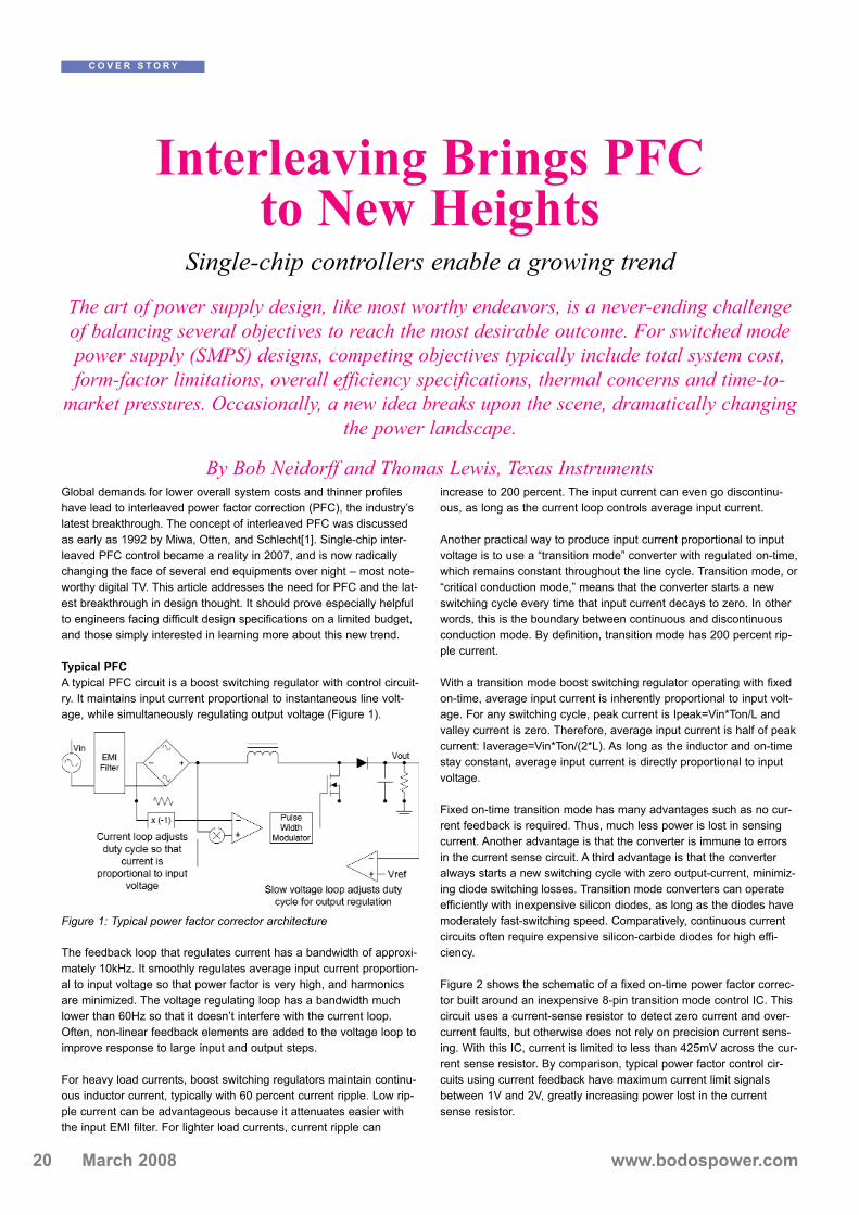
Typical PFCA typical PFC circuit is a boost switching regulator with control circuit-ry. It maintains input current proportional to instantaneous line volt-age, while simultaneously regulating output voltage (Figure 1).
The feedback loop that regulates current has a bandwidth of approxi-mately 10kHz. It smoothly regulates average input current proportion-al to input voltage so that power factor is very high, and harmonicsare minimized. The voltage regulating loop has a bandwidth muchlower than 60Hz so that it doesn’t interfere with the current loop.Often, non-linear feedback elements are added to the voltage loop toimprove response to large input and output steps.
For heavy load currents, boost switching regulators maintain continu-ous inductor current, typically with 60 percent current ripple. Low rip-ple current can be advantageous because it attenuates easier withthe input EMI filter. For lighter load currents, current ripple can
increase to 200 percent. The input current can even go discontinu-ous, as long as the current loop controls average input current.
Another practical way to produce input current proportional to inputvoltage is to use a “transition mode” converter with regulated on-time,which remains constant throughout the line cycle. Transition mode, or“critical conduction mode,” means that the converter starts a newswitching cycle every time that input current decays to zero. In otherwords, this is the boundary between continuous and discontinuousconduction mode. By definition, transition mode has 200 percent rip-ple current.
With a transition mode boost switching regulator operating with fixedon-time, average input current is inherently proportional to input volt-age. For any switching cycle, peak current is Ipeak=Vin*Ton/L andvalley current is zero. Therefore, average input current is half of peakcurrent: Iaverage=Vin*Ton/(2*L). As long as the inductor and on-timestay constant, average input current is directly proportional to inputvoltage.
Fixed on-time transition mode has many advantages such as no cur-rent feedback is required. Thus, much less power is lost in sensingcurrent. Another advantage is that the converter is immune to errorsin the current sense circuit. A third advantage is that the converteralways starts a new switching cycle with zero output-current, minimiz-ing diode switching losses. Transition mode converters can operateefficiently with inexpensive silicon diodes, as long as the diodes havemoderately fast-switching speed. Comparatively, continuous currentcircuits often require expensive silicon-carbide diodes for high effi-ciency.
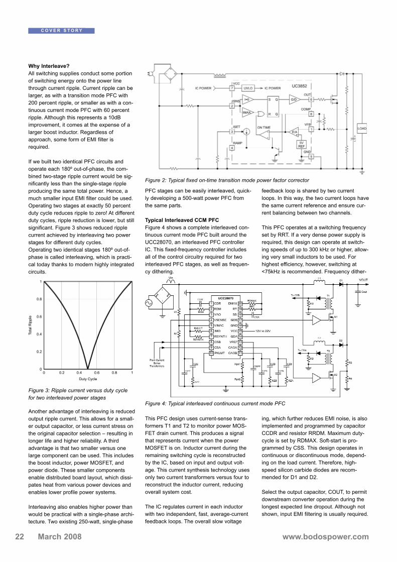
Figure 2 shows the schematic of a fixed on-time power factor correc-tor built around an inexpensive 8-pin transition mode control IC. Thiscircuit uses a current-sense resistor to detect zero current and over-current faults, but otherwise does not rely on precision current sens-ing. With this IC, current is limited to less than 425mV across the cur-rent sense resistor. By comparison, typical power factor control cir-cuits using current feedback have maximum current limit signalsbetween 1V and 2V, greatly increasing power lost in the currentsense resistor.
Figure 1: Typical power factor corrector architecture
22 www.bodospower.comMarch 2008
Why Interleave?All switching supplies conduct some portionof switching energy onto the power linethrough current ripple. Current ripple can belarger, as with a transition mode PFC with200 percent ripple, or smaller as with a con-tinuous current mode PFC with 60 percentripple. Although this represents a 10dBimprovement, it comes at the expense of alarger boost inductor. Regardless ofapproach, some form of EMI filter isrequired.
If we built two identical PFC circuits andoperate each 180º out-of-phase, the com-bined two-stage ripple current would be sig-nificantly less than the single-stage rippleproducing the same total power. Hence, amuch smaller input EMI filter could be used.Operating two stages at exactly 50 percentduty cycle reduces ripple to zero! At differentduty cycles, ripple reduction is lower, but stillsignificant. Figure 3 shows reduced ripplecurrent achieved by interleaving two powerstages for different duty cycles.Operating two identical stages 180º out-of-phase is called interleaving, which is practi-cal today thanks to modern highly integratedcircuits.
Another advantage of interleaving is reducedoutput ripple current. This allows for a small-er output capacitor, or less current stress onthe original capacitor selection – resulting inlonger life and higher reliability. A thirdadvantage is that two smaller versus onelarge component can be used. This includesthe boost inductor, power MOSFET, andpower diode. These smaller componentsenable distributed board layout, which dissi-pates heat from various power devices andenables lower profile power systems.
Interleaving also enables higher power thanwould be practical with a single-phase archi-tecture. Two existing 250-watt, single-phase
PFC stages can be easily interleaved, quick-ly developing a 500-watt power PFC fromthe same parts.
Typical Interleaved CCM PFCFigure 4 shows a complete interleaved con-tinuous current mode PFC built around theUCC28070, an interleaved PFC controllerIC. This fixed-frequency controller includesall of the control circuitry required for twointerleaved PFC stages, as well as frequen-cy dithering.
This PFC design uses current-sense trans-formers T1 and T2 to monitor power MOS-FET drain current. This produces a signalthat represents current when the powerMOSFET is on. Inductor current during theremaining switching cycle is reconstructedby the IC, based on input and output volt-age. This current synthesis technology usesonly two current transformers versus four toreconstruct the inductor current, reducingoverall system cost.
The IC regulates current in each inductorwith two independent, fast, average-currentfeedback loops. The overall slow voltage
feedback loop is shared by two currentloops. In this way, the two current loops havethe same current reference and ensure cur-rent balancing between two channels.
This PFC operates at a switching frequencyset by RRT. If a very dense power supply isrequired, this design can operate at switch-ing speeds of up to 300 kHz or higher, allow-ing very small inductors to be used. Forhighest efficiency, however, switching at<75kHz is recommended. Frequency dither-
ing, which further reduces EMI noise, is alsoimplemented and programmed by capacitorCCDR and resistor RRDM. Maximum duty-cycle is set by RDMAX. Soft-start is pro-grammed by CSS. This design operates incontinuous or discontinuous mode, depend-ing on the load current. Therefore, high-speed silicon carbide diodes are recom-mended for D1 and D2.
Select the output capacitor, COUT, to permitdownstream converter operation during thelongest expected line dropout. Although notshown, input EMI filtering is usually required.
C O V E R S T O R Y
Figure 2: Typical fixed on-time transition mode power factor corrector
Figure 3: Ripple current versus duty cyclefor two interleaved power stages
Figure 4: Typical interleaved continuous current mode PFC
23www.bodospower.com March 2008
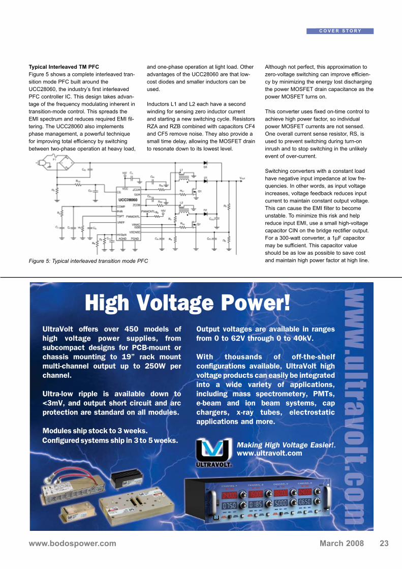
Typical Interleaved TM PFCFigure 5 shows a complete interleaved tran-sition mode PFC built around theUCC28060, the industry’s first interleavedPFC controller IC. This design takes advan-tage of the frequency modulating inherent intransition-mode control. This spreads theEMI spectrum and reduces required EMI fil-tering. The UCC28060 also implementsphase management, a powerful techniquefor improving total efficiency by switchingbetween two-phase operation at heavy load,
and one-phase operation at light load. Otheradvantages of the UCC28060 are that low-cost diodes and smaller inductors can beused.
Inductors L1 and L2 each have a secondwinding for sensing zero inductor currentand starting a new switching cycle. ResistorsRZA and RZB combined with capacitors CF4and CF5 remove noise. They also provide asmall time delay, allowing the MOSFET drainto resonate down to its lowest level.
Although not perfect, this approximation tozero-voltage switching can improve efficien-cy by minimizing the energy lost dischargingthe power MOSFET drain capacitance as thepower MOSFET turns on.
This converter uses fixed on-time control toachieve high power factor, so individualpower MOSFET currents are not sensed.One overall current sense resistor, RS, isused to prevent switching during turn-oninrush and to stop switching in the unlikelyevent of over-current.
Switching converters with a constant loadhave negative input impedance at low fre-quencies. In other words, as input voltageincreases, voltage feedback reduces inputcurrent to maintain constant output voltage.This can cause the EMI filter to becomeunstable. To minimize this risk and helpreduce input EMI, use a small high-voltagecapacitor CIN on the bridge rectifier output.For a 300-watt converter, a 1μF capacitormay be sufficient. This capacitor valueshould be as low as possible to save costand maintain high power factor at high line.
C O V E R S T O R Y
Figure 5: Typical interleaved transition mode PFC
High Voltage Power!UltraVolt offers over 450 models of
high voltage power supplies, from
subcompact designs for PCB-mount or
chassis mounting to 19” rack mount
multi-channel output up to 250W per
channel.
Ultra-low ripple is available down to
<3mV, and output short circuit and arc
protection are standard on all modules.
Modules ship stock to 3 weeks.
Configured systems ship in 3 to 5 weeks.
Output voltages are available in ranges
from 0 to 62V through 0 to 40kV.
With thousands of off-the-shelf
configurations available, UltraVolt high
voltage products can easily be integrated
into a wide variety of applications,
including mass spectrometery, PMTs,
e-beam and ion beam systems, cap
chargers, x-ray tubes, electrostatic
applications and more.
Making High Voltage Easier!®
www.ultravolt.com

24 www.bodospower.comMarch 2008
This converter uses two independent paths to sense output voltage.One senses output voltage using pin VSENSE and divider RC andRD. This sense circuit is used to regulate output voltage and to shutdown the converter in the event of output over-voltage. The secondpath uses pin HVSEN and divider RE and RF. The second pathimplements a redundant over-voltage sensing for safety. It also sens-es the output voltage to switch on the load. Logic output PWMCNTLasserts low when the output voltage is high enough for operation.PWMCNTL de-asserts (goes high impedance) when the output volt-age falls below the dropout threshold, or when one of the powerstages has a fault.
Dealing with Light Load Converters are engineered for many performance attributes at fullload, including peak efficiency, safe operating temperature, reliablecomponent operation, and ability to operate through a power linedropout. However, performance during light-load operation is alsoimportant. Standards like Blue Angel and Energy Plus set efficiencystandards at full load and light load.
Figure 6 compares the efficiency of a typical interleaved PFC operat-ing in both single-phase and two-phase modes. Although interleavinggives excellent efficiency and reliability at full load, light-load efficien-cy is higher with only one-phase switching. This is because energyconsumed slewing drain capacitance becomes more dominant atlight load.
A practical interleaved PFC should switch to single-phase operationat light load. The optimum crossover point is a function of line voltageand other design variables. To facilitate Blue Angel and similar stan-dards, switching to single-phase before 20 percent load realizes max-imum benefit.
At no-load, standards demand extremely low quiescent power con-sumption. While today’s Energy Star® standard allows no more than0.5 Watts, future standards will require under 0.3 Watts – and evenlower standards are expected. To achieve this ultra low power con-sumption, the most practical solution is to completely disable theboost PFC, and run the downstream PWM from the unboosted, recti-fied power line.
The UCC28060 interleaved transition mode PFC (Figure 5) containscircuits for phase management that switch between two-phase, one-phase and shutdown, dependent on load.
Minimizing Acoustic NoiseCapacitors, inductors, heat sinks and shielding can vibrate audiblydue to signals from the switching converter. Switching convertersoperate above 20kHz, but certain line and load conditions can stimu-late audible vibrations.
One example is transitioning from full to light load. Although the out-put capacitor decreases the effect of the load step on the converter,the converter must still change on-time or duty-cycle by a largeamount to regulate output voltage, while the voltage regulation loopmust be slow to provide good power factor.
In this example, some output overshoot is inevitable. If overshoot istoo high, the output capacitor or following power converter could bedamaged. Thus, PFC ICs like the UCC28060 contain error amplifierswith fast, non-linear response to very large overshoot. For someload steps, this quickly brings the output back into regulation. But forthe worst steps, even these fast, non-linear loops can’t respondquickly enough and the output over-voltage protection will trip,switching off the converter. The converter will restart when the outputdrops below the lower over-voltage threshold. It can take a few low-frequency cycles of high-output over-voltage followed by zero loaddecay before the loop is back in regulation.
These low-frequency cycles may be audible or otherwise undesir-able. To prevent this issue, some PFC ICs like the UCC28061 shut-down and restart slowly in response to a severe overshoot. TheUCC28061 is very similar to the UCC28060, but is optimized for sys-tems with very wide load range.
ConclusionThe era of interleaved PFC has arrived and, with it, ushers in newadvancements for power supply designers across the globe. Higherefficiencies, in smaller form factors, at the same or lower overall sys-tem cost are now obtainable. That’s a trend worth talking about!
[1] “High efficiency power factor correction using interleaving tech-niques” Miwa, B.A.; Otten, D.M.; Schlecht, M.E.; APEC ‘92. Confer-ence Proceedings 1992; pp 557–568; Digital Object Identifier10.1109/APEC.1992.228361
www.ti.com
C O V E R S T O R Y
Figure 6: Efficiency comparison for one- and two-phase power con-verters shows a five percent higher efficiency for one-phase opera-tion at light load

26 www.bodospower.comMarch 2008
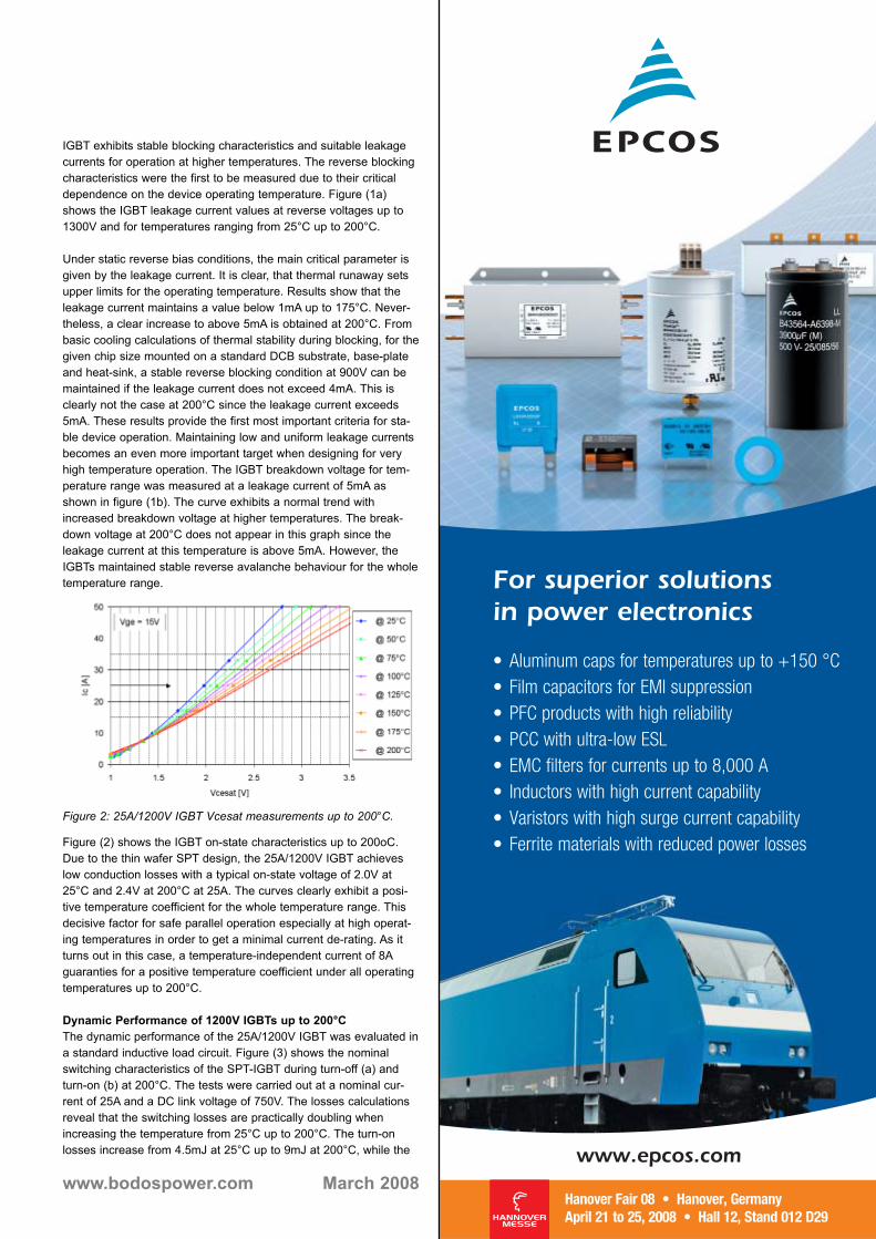
Over the past years, the main development trend for power semicon-ductors was aimed at increasing the power density for a given target-ed application. From the device viewpoint, the limitations are threefold; first is the total losses in the device, second the safe operatingarea boundaries, and finally the maximum allowable junction temper-ature during operation. On the other hand, another limitation existsfor the removal of the power dissipated in the device. However, thischallenge remains a focus of package and system cooling develop-ments.
As state-of-the-art IGBTs slowly approach the limits in terms of lossesreduction, the maximum junction temperature moves more and moreinto the limelight of the interest. The fact that the most importantenabler, namely the power handling capability (SOA) of devices, hasrisen to a level where IGBTs can theoretically be operated at currentsthat greatly exceed the ratings of modern systems has furtherincreased the pressure towards expanding the temperature range.Depending on the rated voltage, IGBTs have so far been limited to150°C (for 1200V and 1700V) or 125°C (2500 V and higher). Sincethe heat flux is proportional to the temperature difference (ΔT), ahigher allowable junction temperature operation of the semiconductoroffers better conduction of the generated heat and hence, anincrease in the power density for a given device area. An increase by25°C enhances the rated power by 25 – 35%, depending on the cool-ing conditions. However, due to the exponential scaling of severalIGBT parameters, such high temperatures will subject the IGBT tonew levels of stress, guiding chip designers and application peopleonto completely new grounds whose firmness is largely unknown.Our analysis started with the thorough characterization of state-of-art1200V IGBTs over a wide temperature range of up to 200°C. Investi-gated parameters included many static characteristics as well asswitching performance and losses tradeoffs. From the resultsobtained, the apparent conclusion is that the IGBTs can still operatewell at 200°C. Unfortunately, this does not yet permit the conclusionthat the devices can be rated for this temperature. In order to drawsuch a conclusion, one must ensure that the IGBTs do not destabilizeas a result of non-uniformities and parameter variations. The strongeremphasis when operating at elevated temperatures will be put onstability issues: the fact that most 1200V IGBTs are run in paralleloperation, raises the danger of current miss-sharing, which mayunder unfavorable conditions lead to thermal runaway and failure of
the devices. Whether or not this happens depends on the tempera-ture-dependent characteristics of the IGBT. Hence, a completeassessment requires that stability criterions are formulated, and thatdevice characteristics are tailored to support stability. The conductedinvestigation represents a fundamental contribution to the discussionof raising the maximum operation temperature for potentially increas-ing the power density of IGBTs.
Static Performance of 1200V IGBTs up to 200°CAll measurements were carried out on a 6.5mm x 6.5mm 1200V Soft-Punch-Through (SPT) IGBT rated at 25A. By implementing a reliableand effective guard ring junction termination and passivation, the
T H E R M A L M A N A G E M E N T
IGBTs Operating at HigherTemperatures
The potentials and the design constraints
The targeted 175°C junction temperature limit for the next generation of 1200V IGBTrequires safe and reliable operation of the devices at a temperature of 200°C. In this arti-cle, we carry out an investigation into the operation of 1200V SPT-IGBTs at temperatures
up to 200°C, in order to understand the potentials and possible threats, while drawinginitial conclusions how such devices must be dimensioned in order to operate safely.
By Ulrich Schlapbach, Munaf Rahimo and Christoph von Arx, ABB Switzerland Ltd., Semiconductors
Figure 1a: 25A/1200V IGBT leakage current measurements.
Figure 1b: 25A/1200V IGBT breakdown voltage vs. temperature.
www.bodospower.com March 2008
IGBT exhibits stable blocking characteristics and suitable leakagecurrents for operation at higher temperatures. The reverse blockingcharacteristics were the first to be measured due to their criticaldependence on the device operating temperature. Figure (1a)shows the IGBT leakage current values at reverse voltages up to1300V and for temperatures ranging from 25°C up to 200°C.
Under static reverse bias conditions, the main critical parameter isgiven by the leakage current. It is clear, that thermal runaway setsupper limits for the operating temperature. Results show that theleakage current maintains a value below 1mA up to 175°C. Never-theless, a clear increase to above 5mA is obtained at 200°C. Frombasic cooling calculations of thermal stability during blocking, for thegiven chip size mounted on a standard DCB substrate, base-plateand heat-sink, a stable reverse blocking condition at 900V can bemaintained if the leakage current does not exceed 4mA. This isclearly not the case at 200°C since the leakage current exceeds5mA. These results provide the first most important criteria for sta-ble device operation. Maintaining low and uniform leakage currentsbecomes an even more important target when designing for veryhigh temperature operation. The IGBT breakdown voltage for tem-perature range was measured at a leakage current of 5mA asshown in figure (1b). The curve exhibits a normal trend withincreased breakdown voltage at higher temperatures. The break-down voltage at 200°C does not appear in this graph since theleakage current at this temperature is above 5mA. However, theIGBTs maintained stable reverse avalanche behaviour for the wholetemperature range.
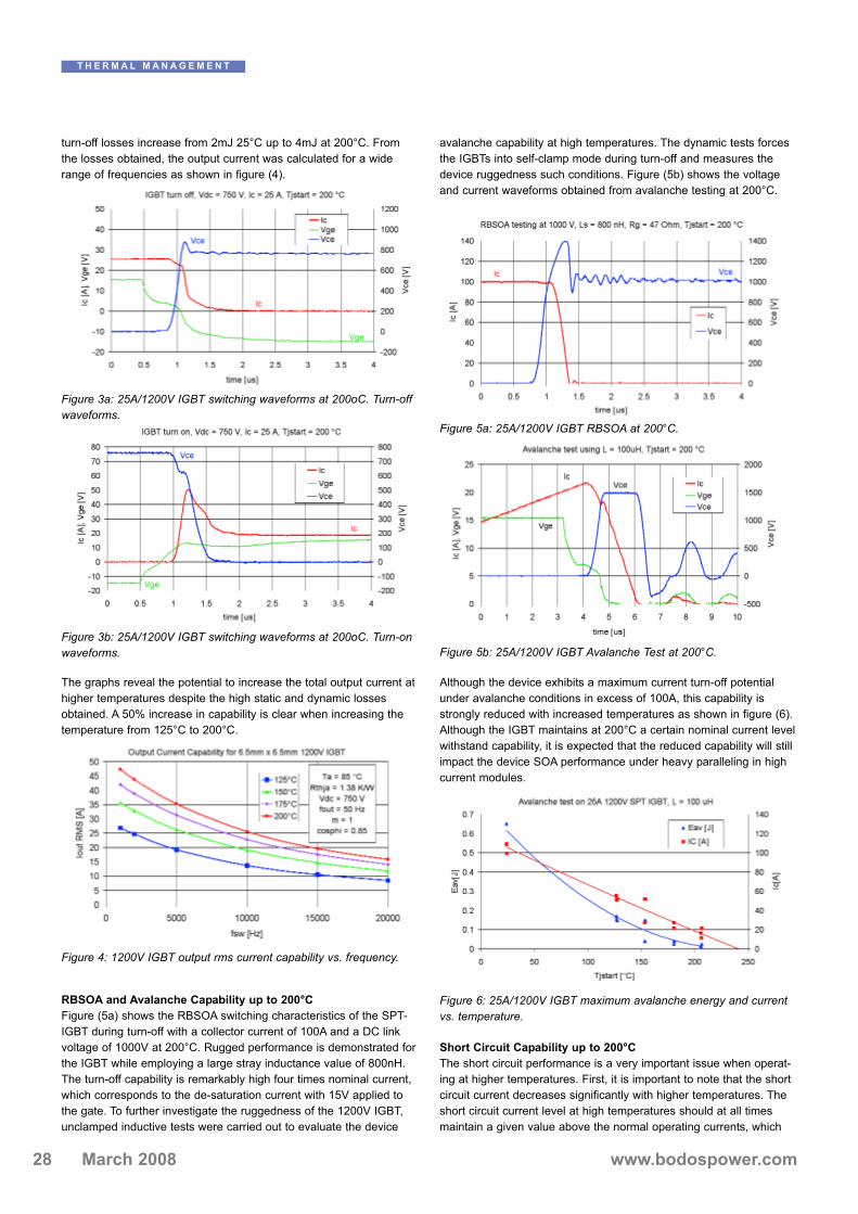
Figure (2) shows the IGBT on-state characteristics up to 200oC.Due to the thin wafer SPT design, the 25A/1200V IGBT achieveslow conduction losses with a typical on-state voltage of 2.0V at25°C and 2.4V at 200°C at 25A. The curves clearly exhibit a posi-tive temperature coefficient for the whole temperature range. Thisdecisive factor for safe parallel operation especially at high operat-ing temperatures in order to get a minimal current de-rating. As itturns out in this case, a temperature-independent current of 8Aguaranties for a positive temperature coefficient under all operatingtemperatures up to 200°C.
Dynamic Performance of 1200V IGBTs up to 200°CThe dynamic performance of the 25A/1200V IGBT was evaluated ina standard inductive load circuit. Figure (3) shows the nominalswitching characteristics of the SPT-IGBT during turn-off (a) andturn-on (b) at 200°C. The tests were carried out at a nominal cur-rent of 25A and a DC link voltage of 750V. The losses calculationsreveal that the switching losses are practically doubling whenincreasing the temperature from 25°C up to 200°C. The turn-onlosses increase from 4.5mJ at 25°C up to 9mJ at 200°C, while the
Figure 2: 25A/1200V IGBT Vcesat measurements up to 200°C.
For superior solutionsin power electronics
www.epcos.com
28 www.bodospower.comMarch 2008
turn-off losses increase from 2mJ 25°C up to 4mJ at 200°C. Fromthe losses obtained, the output current was calculated for a widerange of frequencies as shown in figure (4).
The graphs reveal the potential to increase the total output current athigher temperatures despite the high static and dynamic lossesobtained. A 50% increase in capability is clear when increasing thetemperature from 125°C to 200°C.
RBSOA and Avalanche Capability up to 200°CFigure (5a) shows the RBSOA switching characteristics of the SPT-IGBT during turn-off with a collector current of 100A and a DC linkvoltage of 1000V at 200°C. Rugged performance is demonstrated forthe IGBT while employing a large stray inductance value of 800nH.The turn-off capability is remarkably high four times nominal current,which corresponds to the de-saturation current with 15V applied tothe gate. To further investigate the ruggedness of the 1200V IGBT,unclamped inductive tests were carried out to evaluate the device
avalanche capability at high temperatures. The dynamic tests forcesthe IGBTs into self-clamp mode during turn-off and measures thedevice ruggedness such conditions. Figure (5b) shows the voltageand current waveforms obtained from avalanche testing at 200°C.
Although the device exhibits a maximum current turn-off potentialunder avalanche conditions in excess of 100A, this capability isstrongly reduced with increased temperatures as shown in figure (6).Although the IGBT maintains at 200°C a certain nominal current levelwithstand capability, it is expected that the reduced capability will stillimpact the device SOA performance under heavy paralleling in highcurrent modules.
Short Circuit Capability up to 200°CThe short circuit performance is a very important issue when operat-ing at higher temperatures. First, it is important to note that the shortcircuit current decreases significantly with higher temperatures. Theshort circuit current level at high temperatures should at all timesmaintain a given value above the normal operating currents, which
T H E R M A L M A N A G E M E N T
Figure 5a: 25A/1200V IGBT RBSOA at 200°C.
Figure 5b: 25A/1200V IGBT Avalanche Test at 200°C.
Figure 6: 25A/1200V IGBT maximum avalanche energy and currentvs. temperature.
Figure 3a: 25A/1200V IGBT switching waveforms at 200oC. Turn-offwaveforms.
Figure 3b: 25A/1200V IGBT switching waveforms at 200oC. Turn-onwaveforms.
Figure 4: 1200V IGBT output rms current capability vs. frequency.

29www.bodospower.com March 2008
T H E R M A L M A N A G E M E N T
are typically equal to twice the rated current. This is vital for ensuringcontrollable turn-on behaviour and low switching losses. Normally,short circuit operation raises three major concerns: (i) short circuitturn-on failures due to field distortion, (ii) short circuit turn-off failuresbecause of latch-up, and (iii) thermal runaway due to excess energyduring short circuit. The first concern is normally associated withhigher currents and lower temperatures. Thus, operation at a highertemperature will not have a negative impact. The second concernrelates to the device ruggedness, which was addressed earlier.Therefore, the main focus here is with regard to concern (iii). Figure(7a) shows the results obtained from short circuit tests carried out at25°C and 200°C for two different pulse widths respectively. The junc-tion temperature was plotted using adiabatic thermal calculations forTj of the chip silicon volume heated up by the short circuit pulse, andconfirmed by the temperature dependence of the short circuit current.
It was observed that thermal runaway occurs for devices starting at ahigher temperature, however failing with a lower peak junction tem-perature at the end of the short circuit pulse. This is due to reducedtransient cooling at high ambient temperatures. From destructivemeasurements due to excess energy at a wide temperature range,two plots were generated for the short circuit energy and correspon-ding pulse width versus temperature as shown in figure (7b). As canbe seen clearly, the maximum allowable energy and pulse width hasdropped considerably at higher temperatures. This approach couldbe overcome either by reducing the short circuit current with limita-tions regarding controllable switching behaviour as mentioned earlier,or by shortening the short circuit withstand duration as is currentlywidely discussed.
The results presented in this article for a 1200V SPT-IGBT bring forthimportant data with regard to the device behaviour for future applica-tions that aim for a permanent higher temperature operation. Themain conclusion points out to stable behaviour for the device at high-er temperatures with clear limitations in terms of leakage current,avalanche capability and short circuit performance. Moreover, today’sapplications with requirements for an intermittent operation lifetimeand safe operation limits will also benefit from a better knowledge ofthe margins in order to estimate the effects of transient or exceptionalhigh temperature conditions. Focus must also be directed towardsthe reliability aspects of high temperature operation, which is stronglylinked to the packaging technology.
www.ABB.com/semiconductor
Figure 7a: 25A/1200V IGBT short circuit waveforms at 25°C andoverlaid short circuit current at 200°C.
Figure 7b: Short circuit energy and pulse width versus temperature.
Bicron Electronics Companywww.bicronusa.com 1 800 624 2766, 1 860 824 5125, +45 9858 1022
HF Transformer Types:
When power control failure is not an option . . .
High Frequency Transformersfor High Value Systems
applications >25Kw
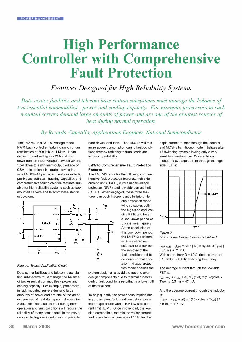
30 www.bodospower.comMarch 2008
The LM3743 is a DC-DC voltage modePWM buck controller featuring synchronousrectification at 300 kHz or 1 MHz. It candeliver current as high as 20A and stepdown from an input voltage between 3V and5.5V down to a minimum output voltage of0.8V. It is a highly integrated device in asmall MSOP-10 package. Features include;pre-biased soft-start, tracking capability, andcomprehensive fault protection features suit-able for high reliability systems such as rackmounted servers and telecom base stationsubsystems.
Data center facilities and telecom base sta-tion subsystems must manage the balanceof two essential commodities - power andcooling capacity. For example, processorsin rack mounted servers demand largeamounts of power and are one of the great-est sources of heat during normal operation.Substantial increases in heat during normaloperation and fault conditions will reduce thereliability of many components in the serverracks including semiconductor components,
hard drives, and fans. The LM3743 will min-imize power consumption during fault condi-tions thereby reducing thermal loads andincreasing reliability.
LM3743 Comprehensive Fault ProtectionFeaturesThe LM3743 provides the following compre-hensive fault protection features: high sidecurrent limit (HSCL), output under-voltageprotection (UVP), and low side current limit(LSCL). When engaged, these three fea-tures can each independently initiate a hic-
cup protection modewhich disables boththe high-side and low-side FETs and begina cool down period of5.5 ms, see Figure 2.At the conclusion ofthis cool down period,the LM3743 performsan internal 3.6 mssoft-start to check forthe removal of thefault condition and tocontinue normal oper-ation. Hiccup protec-tion mode enables the
system designer to avoid the need to overdesign components due to thermal runawayduring fault conditions resulting in a lower billof material cost.
To help quantify the power consumption dur-ing a persistent fault condition, let us exam-ine an application with a 10A low-side cur-rent limit (ILIM). Once in overload, the low-side current limit controls the valley currentand only allows an average of 10A plus the
ripple current to pass through the inductorand MOSFETs. Hiccup mode initializes after15 switching cycles allowing only a verysmall temperature rise. Once in hiccupmode, the average current through the high-side FET is:
IHSF-AVE = (ILIM + ΔI) x [ D(15 cycles x TSW) ]/ 5.5 ms = 71 mAWith an arbitrary D = 60%, ripple current of3A, and a 300 kHz switching frequency.
The average current through the low-sideFET is:ILSF-AVE = (ILIM + ΔI) x [ (1-D) x (15 cycles xTSW) ] / 5.5 ms = 47 mA
And the average current through the inductoris:IL-AVE = (ILIM + ΔI) x [ (15 cycles x TSW) ] /5.5 ms = 118 mA
P O W E R M A N A G E M E N T
High Performance Controller with Comprehensive
Fault Protection Features Designed for High Reliability Systems
Data center facilities and telecom base station subsystems must manage the balance oftwo essential commodities - power and cooling capacity. For example, processors in rack
mounted servers demand large amounts of power and are one of the greatest sources ofheat during normal operation.
By Ricardo Capetillo, Applications Engineer, National Semiconductor
Figure1. Typical Application Circuit
Figure 2. Hiccup Time Out and Internal Soft-Start

Protecting Typical Fault Conditions inHigh-Reliability SystemsServer racks and telecom base station sub-systems require high reliability to enableuninterrupted flow of data and communica-tion. When unexpected failures occur, theLM3743 fault protection features can help toprevent further electrical and thermal stress.Examining some typical system fault condi-tions, we can elaborate on the protectionmodes of the LM3743 device and the opera-tional benefit:
A capacitor such as a POS-cap located atthe output of the LM3743 fails as a short cir-cuit after an over-voltage surge exceeds themaximum capacitor voltage rating, refer toFigure 3. In such a situation duty cycle andthe inductor current increase cycle by cycle,but fortunately input current is decreasedbecause the LM3743s' UVP initializes Hic-cup-Mode.
A small piece of metal falling into the productfrom the outside or a piece of metal that wasloose in the product changes positions dur-ing shipment and lands across the switchnode (VSW) and ground, see Figure 4. Highside current limit immediately senses theshort circuit fault condition.
Excessive load and/or incorrect selection ofthe MOSFET results in an open circuit fail-ure. For example; if the low side MOSFET(Q2) fails, depicted in Figure 5, the inductorcurrent will not flow during the time Q2should be on, thus the inductor current willincrease cycle by cycle. The high side cur-rent limit will capture the over current event,thereby protecting the high side MOSFET(Q1) from over heating and failure.
In all these situations the LM3743 providesfault protection, reduces the average input
current and relieves the power componentsfrom thermal stress during persistent faultconditions. After the removal of the faultcondition, the LM3743 performs an automat-ic self test and recovery sequence. Userintervention is not required, in so reducesmaintenance cost and designed in circuitcomplexity.
The LM3743 provides comprehensive faultprotection and a reduction in server powerconsumption during fault conditions. It alsocombines high efficiency with high drivecapabilities for loads up to 20A. With theLM3743, the balance between power andcooling capacity are much more manageableduring device failure and short circuit condi-tions.
www.national.com
31www.bodospower.com March 2008
P O W E R M A N A G E M E N T
Figure 3. Output Short-Circuit to Ground
Figure 4. Switch Node Short-Circuit toGround Figure 5. Low Side MOSFET Open-Circuit
Failure
MiniPack 2 - IGBT Module with Converter Brake InverterAvailable in latest NPT andtrench IGBT technologies
Features• 10 - 30 A, 600 - 1200 V• Insulated base plate (DCB)• Pins suitable for wave soldering• High level of integration (NTC included)• Hiperfast free wheeling• Custom and standard configurations• Assembly clips available
Used in:• AC motor drives:
– Pumps, fans– Washing machines– Air-conditioning systems
• UPS
EUROPE:IXYS Semiconductors [email protected]
USA:IXYS [email protected]
ASIA:IXYS [email protected]

March 2008
In safety related electronic systems, likebrake and door control systems used intrains or busses, system interruptions mustbe prevented. Supply line disturbances mayhave several sources, for example:
- A sudden opening, or switch bounce onclosing, of the supply lines switches
- Additional switch on of large capacitiveloads parallel to the voltage converterinput
- A short circuit at other loads sharing thesupply, during the fuse clearing time
Voltage converters must provide a very sta-ble output voltage – not changing throughinput and output changes. Railway batterysupply voltages may vary over a wide range– possibly fluctuating ±40% from nominalvalues. At a battery system nominal voltageof 72V, a dc/dc converter must operate safe-ly from 43V to 101V input voltage. Withinthese limits the converter must provide a sta-ble output voltage, for example, 12V or 24V.And output voltage must be stable duringchanges in load current from zero to fullload. In addition, there are more dynamicdeviations of the board system voltage.These may be caused by load changes onthe battery, e.g. switch in of high currentloads or short circuit conditions, with a com-mon source impedance due to long line wiredistances of 50m … 100m. (See Fig 1 + 2).
Voltage drops at the system board voltage ofup to 1msec can be compensated for withthe output smoothing capacitance of stan-dard classic DC/DC converters working withswitching frequencies between 25kHz and250kHz. This is possible when allowing anoutput voltage drop of 5% from nominal,which the electronic load will tolerate. (SeeFigure 3).
However, converters with higher switchingfrequencies of 400kHz to 1 MHz, (e.g. reso-nant converters) have only a small outputcapacitances of a few μF. With this smallcapacitance essentially no hold up time isprovided. Capacitors must be connected inparallel to the load, outside of the converterif necessary.
Example: 50W converter, Vout = 12V, Iout = 4A, Cout= 8mF (8000 μF), 5% Voltage drop.
Hold up time, as provided by the storedenergy in the 8mF output capacity, can becalculated from Equation (1):
I = C dv/dt ……. Equation (1)Δt = C * Δ V / I → t = 8mF * (12V *.05)/
4A = 1.2msec
(neglecting an allowance for capacitor seriesresistance, aging, dry out of electrolytes, andline resistance).
P O W E R Q U A L I T Y
32 www.bodospower.com
Voltage Drops on Battery Lines, of 3ms – 6 sec, Can Cause Interrupts
Converters 10W - 500W DC/DC avoid system interruptions
Supply line interruptions and voltage drops on battery wiring may lead to unexpected system behaviour in electronic systems.
By Willi Spiesz, Grau Elektronik, Karlsbad, Germany
Figure 1: Battery Voltage Net
Figure 2: Battery Voltage and Load Current
Figure 3: Input Voltage Drop Figure 4: In- Output Voltage Drop

Supply line disturbances and voltage drops,as short as 100usec, may cause the con-verter to switch off. Such short interruptionshave no influence on the secondary elec-tronic side. The assumption is that the elec-tronic load can handle a voltage reductionfrom nominal of 5% and the DC/DC convert-er has enough storage capacity and no softstart or any other delaying factors when itwas switched off. The reaction time to switchoff the converter is typ. 0.1ms - 0.3msec.Therefore the converter does not react tosmaller line disturbances. But converters areprotected for longer interrupts as input cur-rents may become excessive.
Typical voltage drops from the commonsource impedance of battery lines, e.g.caused through fuse blowing or crowbar pro-tection elements like “transil” diodes blowinga fuse, can cause voltage dips with timedurations between 0.1msec and 25msec.
The input operating voltage range of voltageconverters is measured with under and over-voltage monitoring stages to avoid operationoutside the specified input voltage range.This means, that if the battery voltagedecreases to a value below the defined limit,
in our example below 43V, the DC/DC con-verter is switched off. Otherwise the dutycycle, relation ton / switching period, for theswitching power transistor and diode wouldbecome too high and eventually damage thetransistor or diode. Right after switching offof the converter, the output voltage decreas-es. The restart of the converters or electron-ics can lead to a much longer system inter-rupt than the duration of the battery line dis-turbance, caused by soft start or boot proce-dures.
For railway systems there are different holdup times for nominal voltage and load speci-fied as follows:
S1: no hold up time requiredS2: 10ms
The railway standard EN50155 referencesthe S2 hold up time of 10ms only to Vnomi-nal. This can cause some problems, as highbattery voltage provides longer hold uptimes, low battery voltage shorter hold uptimes.
Line voltage drops are undefined and ran-dom in occurrence and repetition rate. To
avoid disturbances during whole life cycle ofa voltage converter, e.g. 20 years, the holdup time design must be done careful. Forexample, aging of aluminium electrolyticcapacitors during this period will be stronglyinfluenced by dry out caused by heating ofthe electrolyte.
When relative long hold-up times are need-ed, energy storage cannot easily be provid-ed by secondary output smoothing capaci-tors. The hold up time is then realized on theprimary side of the converter - also by alu-minium electrolytic capacitors, but at a high-er voltage level. Grau Elektronik convertersare available for hold up times, dependingon output power (5W …. 500W), between10ms and 6 seconds.
P O W E R Q U A L I T Y
MAKING MODERN LIVING POSSIBLE
Simplify your design!
Danfoss Silicon Power GmbH
We design and manufacture to your needs.
Visit us
at the PCIM 2008
27. Mai – 29. Mai
Booth 12-325
Figure 5: Input Short Circuit, Energy Direction
34 www.bodospower.comMarch 2008
Hold up time can be evaluated with the following equation: W = ½ CV² (Eqn.2)
Referencing the example converter with Pout = 50W, with t = 10ms,leads to the capacitance value necessary:C ≥ 2 * P / η * t / [V2² - V1²],2 * 50W / 0.85 * 0.01s / [(72V)² - (43V)²] = 352μF
Hold up time through charging of AL capacitors on the boardsystem nominal voltageThis equation, Eqn. (2), is only a rough estimation, because eachDC/DC converter appears to have a negative input resistive behav-iour in its current consumption. That is, high input voltage means lowinput current and low input voltage high current. The capacitor dis-charge time can be evaluated more exactly with the following equa-tion:V(t) = Vo * e-t/RC Equation (3)
Vo = charge voltage, V(t) = time dependent discharge voltage beforethe converter switches off, R = v(t)²/P*, C = capacity of the chargingcapacitor, P* = input power of the converter.
Rearanging Equation (3) and solving for t:t = - ln (43V/72V) * ((72V/0.81A + 43V/1.36A))/2 * 660μF = 20.1ms
Therefore two capacitors, rated at 330μF / 160V, are necessary.The tolerance of the manufacturer is typically ± 20% so the worst-case scenario provides Cmin = 660μF * 0.8 = 528μF. With C =Cnominal – 20% there are still 16ms available. In meeting a 10msechold up requirement, this allows 5.1ms for aging of the capacitors,voltage drop at the decoupling diode, as well as series resistance.The stored energy is also a function of Vin.
When the hold-up capacitor is charged only to 65V (Vin,nom – 10%),the hold up time is only t = 16.3ms (660μF), t = 13.1ms (528μF respectively.
This requires charging capacitors with higher voltage class than thebattery line voltage. At higher voltages it is possible to store moreenergy in smaller volumes. Therefore, at Grau, we use a regulatedauxiliary voltage that is independent from the line voltage of about100V. The capacitances C for 10ms then becomes:C ≥ 2 * P / η * t / [U2² - U1²], 2 * 50W / 0.85 * 0.01s / [ (100V)² -(43V)²] = 144μF.
One capacitor with C = 330μF at a voltage of 160V is enough to geta reliable hold-up time over the life of the converter. t = - ln (43V/100V) * ((72V/0.81A + 43V/1.36A))/2 * 330μF = 16.7ms
Also, with a – 20% tolerance from the nominal capacitance, the holdup time still is:t = - ln (43V/100V) * ((72V/0.81A + 43V/1.36A))/2 * 264μF = 13.1ms
It is necessary that the stored energy not flow back to the shortedinput - otherwise there would be no advantage from the stored ener-gy. This can be easily avoided by a series diode, for example.
For higher output power converters, 150W, 250W or 500W, energystoring with high voltage capacitors provides space and cost savings.
Both methods have their advantages and disadvantages. Whencharging capacitors directly from the battery line, the input currentsurge in a totally discharged cap must be considered - otherwise the
input fuse will fail, or at least age prematurely. Charging capacitors toa higher voltage than the input line voltage means a little bit moreeffort in the electronics. The advantage is independence from batteryvariations and always the same hold up time.
Grau Elektronik converter designs have hold up circuits that are inde-pendent from input voltage fluctuations. With this concept, neithertemperature nor input voltage influences hold-up time. Reliable andeasily controllable hold-up times at optimized space relations arerealized.
Grau Elektronik dc/dc converters, with galvanic isolation, series WBB50W to 150W, and dc/dc converters, series DDB 250W, 500W, haveefficiencies between 87% and 91% over the full input voltage rangeand over their rated output range of 20% to 100%.
www.grau-elektronik.de

www.sensor-test.com
Organiser:AMA Service GmbH · Tel. +49(0)5033 96390 · [email protected]
6. – 8.5.2008Nürnberg, Germany
15th International Trade Fair for Sensorics, Measuring andTesting Technologies with concurrent Conferences:
- OPTO 2008 – 8th International conference on OpticalTechnologies for Sensing and Measurement
- IRS2 2008 – 10th International Conference on InfraredSensors and Systems
Schedule now!
www.sensor-test.com

www.bodospower.comMarch 200836
P A C K A G I N G
Something New Has Been AddedAttention all Space, Military, Aerospace,
Hi-Rel Power semiconductor users.
A new Power Semiconductor Package, The Ecconowatt, has been designed and the concept patented. It is Ceramic, Hermetic, Surface Mountable, Lightweight, assembly
friendly, with short cycle time and most importantly Low Cost.
By Robert Satriano, CNS Power Ceramix
A New Power Semiconductor package hasbeen designed and the concept patented. Itis Ceramic, Hermetic, Surface mountable,Lightweight, Assembly friendly and Automat-able, with Short cycle time and Firstly andmost importantly Low Cost.
The manufacturing process to produce TheEcconowatt is proprietary and it is the tech-nique used and the experience acquired inceramics that provides the assurance toallow all the above characteristics to be met.CNS Power Ceramix, A company founded bya business man, a ceramic engineer, and anassembly manufacturing systems and pack-aging engineer, represent the management. This team is dedicated to producing theEcconowatt packaging concept in a mannerthat takes into consideration the PackageManufactures, the Device assembly house,and above all the Users.The package is designed in strip form (5 perstrip) Similar to the Plastic ManufacturingSystem. This allows automatic die attach-ment and wire bonding operations adequatelanding area has been provided to allowmultiple wire bonds if necessary.
Thermal Resistance is addressed by brazinginto the five position strip base a slug of Sili-con Cemented Diamond which thermal con-ductivity is 580 W/mK. Being all ceramic, the strip can be tested instrip form which allows a yield check anddiscounts the need to assemble a cap on areject.Ceramic caps and a low temperature Eutec-tic pre-form material is loaded into a slot inthe base strip of five and then vacuumsealed.After sealing the strips are put through aseparation fixture which allows the separateddevices to be loaded into plastic shippingsticks.The devices can be marked or branded inthe stick prior to shipment to the customer.In reading this narrative it should havebecome evident that CNS managementteam are confident that this package conceptwill be used for all Power Semiconductors.As mentioned earlier in this text getting any-thing new to the market place is a discourag-ing realization but change is inevitable andwill occur when the risk and effort justifiesthe need.
The Ecconowatt name was adoptedbecause it represents a product that suppliespower at low cost, with absolute reliability.The inventors of the TO-220 plastic encap-sulated package named it the Versawatt dueto its versatility to various levels of powerdevices to the users.
The Ecconowatt will be accepted as thepackage of choice for Power Semiconduc-tors but not before the ultimate usersbecome aware of its existence and demandit for their products.CNS stands ready and waiting to assist allHi Rel requirement product manufacture withdesign information. CNS needs your supportto get this Ecconowatt style packaging con-cept to the users.
Power Semiconductor packaging has nothad any innovation since the advent of ther-mo-set plastic encapsulation technologyintroduction in the 1970's.A few Hermetic packages have surfaced thatmimic the plastic package configuration.These packages are expensive, difficult toproduce, not assembly friendly and usersare clamoring for something new.
Figure 1: To 254 versus Ecconowatt

37www.bodospower.com March 2008
P A C K A G I N G
Power Semiconductor packaging underwenta change in the 1970's. From hermetic "tincans" to silicone plastic encapsulated pack-ages. Cost being the major driver, wasinstrumental in changing over some deviceusers to the plastic package but Reliabilitydid not meet the old "tin can" standards.
A change from silicone plastic to epoxy wasa step in that direction. Epoxy, found toimprove reliability was now in vogue, howev-er this change did not fully remedy the issueand many users were reluctant to make thechange to plastic encapsulated devices.Epoxy brought forth an entirely new set ofproblems. Wire bonds were being ripped offbond pads on the chip due to the "GlassTransition Temperature" factor creating thecoefficient of expansion to accelerate expo-nentially. Epoxy was a help in many respectsbut created other issues that had to beaddressed. A correction to this issue camewith the plastic manufactures filling theepoxy powder with "glass" to lower the"Glass Transition Temperature" to be suit-able enough to achieve reliability accept-ance. Glass filled epoxy powder gave the Rel com-munity what they demanded and deviceusers were satisfied.Although reliability improved significantly, thefactory suffered, molds, post mold tools andall equipment associated with the glass filledepoxy began to quickly show wear and needof replacement. The cost now became theproblem. The additional maintainance costswere eating into the margin and demandedimmediate attention.
The mold makers used different steel, andapplied very expensive coating to the moldcavities which improved the life of the moldsand tooling.
Now Product Engineering, Reliability Engi-neering, the factory, and device users wereat a point where they considered the PlasticEncapsulated Semiconductor to be "GoodEnough", However continued Rel testingrevealed that since these devices were nothermetically sealed the solder used to attachthe power chip to the copper lead frame was
being attacked by O². It was foundthat after power cycling, microcracks formed in the solder underthe chip and continue to propa-gate until finally the chip is sev-ered from the base. The device continues to functiondue to the compression forces ofthe epoxy exerted upon the chipto maintain contact with the base. Although this condition is trouble-some no one has voiced a con-cern since the Rel data did notchange.
Hermetic packaged Power devicesales began to decline giving wayto the plastic system.Device users for Space, Hi Rel,and Military applications began toshow an interest in "New" Hermeticpackaging concepts that allow theleads to exit the top and side of the packagesimilar to the plastic version as opposed tothe old "tin cans" having the leads protrudefrom the bottom side.After years of continued requests this typepackage was offered to the Military, Space,and Hi Rel users.A typical design is the JEDEC outline TO-254. Although, this package met the leadrequirement to exit the top side of the pack-age and matched the appearance of its plas-tic cousin, it was not assembly friendly. Nev-ertheless, this design was becoming accept-able regardless of cost, difficulty in deviceassembly and package fabrication. Sincevolumes for these devices were low and costnot a factor for Hi Rel, Military and Spaceusers this geometrical configuration thrived.
The package was plagued with considerableproblems which dealt primarily with her-meticity and therefore changes had to bemade which only added to the cost.An acceptable manufacturing process wasfinally established that satisfied reliability andhermeticity requirements but not without pay-ing the penalty of cost. The cost of the TO-254 when first introduced ranged in theneighborhood of $28 each. It now sells for$4-$6 at a volume level of 50,000 per month.
It is evident that the users of this TO-254concerned themselves only with the fact thatthe package was hermetic which connotesreliability and paid the price to acquire theproduct.
Being acquainted with the evolution ofPower Semiconductor Packaging and howpassionate the engineers were who inventedand generated these geometrical configura-tions, it displeases me to see the "Its GoodEnough" attitude prevail because to make achange in a packaging design and have itaccepted is a monumental task.
Selling any new concept, passing reliability,passing customer qualification is enough todiscourage change because it takes perse-verance and a lot of blood, sweat and tearsto get anything new and different into cus-tomer products. This discouraging realization is paramount inhaving an new power semiconductor pack-age emerge.
CNS feels very strongly that once this pack-age gets into the hands of device manufac-ture and users, it will ultimately become thechoice for all power semiconductors. Thedesign lends itself to high volume productionand will compete with plastic encapsulatedpackaging costs at the high volume levels.Please contact CNS at the email addressbelow and share with us your needs as weare totally committed and prepared to help. Currently the Ecconowatt is being consid-ered for the automotive ignition circuit driverwhich only tells you about the flexibility of itsdesign.
WWW.CNSCERAMIX.COMFigure 2a: Weight Comparison Figure 2b: Thermal Comparison
Figure 1: To 254 versus Ecconowatt
Package Comparison Data
To-254 ECCONOWATT Cost $5.00 $1.40Weight 5.8g 1.5g Footprint & height .540”x.800x.255” .540”x.800x.200” Chip attached to… Tungsten copper Silicon Cemented
Diamond Thermal Conductivity
1.47 watts 5.5 watts
Package body material
Steel Ceramic
Lead material 52 alloy Steel Lead disposition Cantilevered To base Lead seal Glass or Ceramic Ceramic Surface mountable Lead forming
Required YES
Package fabrication Difficult & lengthy Simple Assembly automatable
NO YES
Device Manufacturing Time
LONG SHORT
Corrosion Property POOR EXCELLENT Package Handling One at a time Strip of Five *Includes Cap 50,000/month

38 www.bodospower.comMarch 2008
The electronics industry’s unrelenting demand for smaller, more reli-able circuit protection devices continues to drive the miniaturizationtrend. As a result, circuit protection device manufacturers must pro-vide their OEM customers with smaller and smaller devices; but theobjective is clearly more than size reduction. The real challenge liesin scaling down component size without sacrificing electrical charac-teristics. Advanced material research and technology has been thekey to developing new devices that meet existing performance levelswithin smaller, more reliable, and more convenient packaging.
Another important design challenge is the need for coordinated circuitprotection. Because overcurrent and overvoltage protection are oftenviewed as two unrelated elements of the design process, protectionstrategies can result in costly multi-component solutions, and syner-gies between protective devices can be overlooked. Coordinatingthese devices or integrating overcurrent and overvoltage protectionfunctions in a single device effectively reduces component count and,appropriately applied, can expand performance attributes and helpimprove system reliability.
Following are three examples of how Tyco Electronics’ applied inno-vation in circuit protection materials and technology can help designengineers conserve valuable board space and meet evolving safetyand performance standards.
The new 2Pro™ device integrates overcurrent and overvoltage circuitprotection technology to help prevent damage to telephony communi-cations equipment. The device’s small footprint, resettable functionali-ty and coordinated protection capabilities make it suitable for a widerange of telephony and VoIP equipment applications such as cord-less phones, VoIP gateways, data modems, set-top boxes, securitysystems, MDF (Main Distribution Frame) modules, analog linecardsand ISDN (Integrated Services Digital Network) linecards.
The RoHS-compliant 2Pro device incorporates PolySwitch™ PPTCovercurrent technology with an MOV component into one thermallyprotected device that helps provide current limiting during overcurrentevents and voltage clamping during overvoltage events. This single-device approach helps reduce component count and improve equip-ment reliability. Figures 2 and 3 illustrate how the 2Pro device is usedin both an ungrounded and grounded circuit protection scheme.
P R O T E C T I O N
Circuit Protection Designs for aConnected World
Integrating overcurrent and overvoltage protection
The demand for more and more features and functions in consumer electronics presentsnew challenges to design engineers. Circuit protection device manufacturers must also
continue to deliver new solutions to support emerging technologies and meet new systemlevel protection requirements.
By Adrian Mikolajczak, Tyco Raychem Circuitprotection
Figure 1. 2Pro™ Device helps protect telephony and VoIP equip-ment.
Figure 2. 2Pro in ungrounded system
Figure 3. 2Pro in grounded system
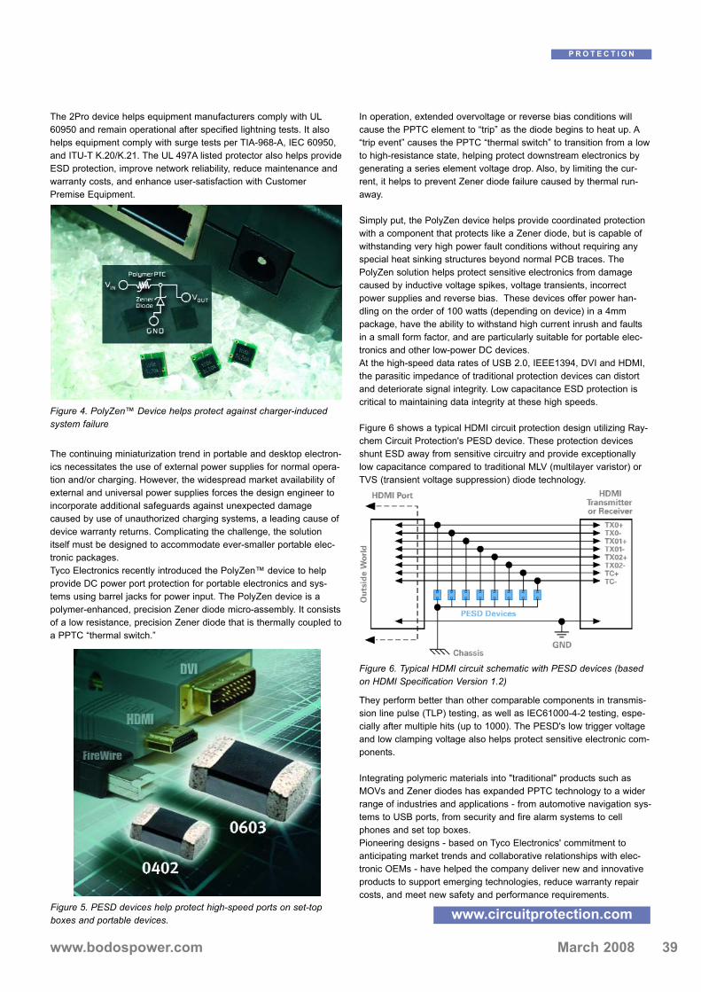
39www.bodospower.com March 2008
The 2Pro device helps equipment manufacturers comply with UL60950 and remain operational after specified lightning tests. It alsohelps equipment comply with surge tests per TIA-968-A, IEC 60950,and ITU-T K.20/K.21. The UL 497A listed protector also helps provideESD protection, improve network reliability, reduce maintenance andwarranty costs, and enhance user-satisfaction with CustomerPremise Equipment.
The continuing miniaturization trend in portable and desktop electron-ics necessitates the use of external power supplies for normal opera-tion and/or charging. However, the widespread market availability ofexternal and universal power supplies forces the design engineer toincorporate additional safeguards against unexpected damagecaused by use of unauthorized charging systems, a leading cause ofdevice warranty returns. Complicating the challenge, the solutionitself must be designed to accommodate ever-smaller portable elec-tronic packages. Tyco Electronics recently introduced the PolyZen™ device to helpprovide DC power port protection for portable electronics and sys-tems using barrel jacks for power input. The PolyZen device is apolymer-enhanced, precision Zener diode micro-assembly. It consistsof a low resistance, precision Zener diode that is thermally coupled toa PPTC “thermal switch.”
In operation, extended overvoltage or reverse bias conditions willcause the PPTC element to “trip” as the diode begins to heat up. A“trip event” causes the PPTC “thermal switch” to transition from a lowto high-resistance state, helping protect downstream electronics bygenerating a series element voltage drop. Also, by limiting the cur-rent, it helps to prevent Zener diode failure caused by thermal run-away.
Simply put, the PolyZen device helps provide coordinated protectionwith a component that protects like a Zener diode, but is capable ofwithstanding very high power fault conditions without requiring anyspecial heat sinking structures beyond normal PCB traces. ThePolyZen solution helps protect sensitive electronics from damagecaused by inductive voltage spikes, voltage transients, incorrectpower supplies and reverse bias. These devices offer power han-dling on the order of 100 watts (depending on device) in a 4mmpackage, have the ability to withstand high current inrush and faultsin a small form factor, and are particularly suitable for portable elec-tronics and other low-power DC devices. At the high-speed data rates of USB 2.0, IEEE1394, DVI and HDMI,the parasitic impedance of traditional protection devices can distortand deteriorate signal integrity. Low capacitance ESD protection iscritical to maintaining data integrity at these high speeds.
Figure 6 shows a typical HDMI circuit protection design utilizing Ray-chem Circuit Protection's PESD device. These protection devicesshunt ESD away from sensitive circuitry and provide exceptionallylow capacitance compared to traditional MLV (multilayer varistor) orTVS (transient voltage suppression) diode technology.
They perform better than other comparable components in transmis-sion line pulse (TLP) testing, as well as IEC61000-4-2 testing, espe-cially after multiple hits (up to 1000). The PESD's low trigger voltageand low clamping voltage also helps protect sensitive electronic com-ponents.
Integrating polymeric materials into "traditional" products such asMOVs and Zener diodes has expanded PPTC technology to a widerrange of industries and applications - from automotive navigation sys-tems to USB ports, from security and fire alarm systems to cellphones and set top boxes. Pioneering designs - based on Tyco Electronics' commitment toanticipating market trends and collaborative relationships with elec-tronic OEMs - have helped the company deliver new and innovativeproducts to support emerging technologies, reduce warranty repaircosts, and meet new safety and performance requirements.
www.circuitprotection.com
P R O T E C T I O N
Figure 5. PESD devices help protect high-speed ports on set-topboxes and portable devices.
Figure 4. PolyZen™ Device helps protect against charger-inducedsystem failure
Figure 6. Typical HDMI circuit schematic with PESD devices (basedon HDMI Specification Version 1.2)

40 www.bodospower.comMarch 2008
The scooter's powertrain incorporates amagnet system containing VACODYM® 655AP magnets from Vacuumschmelze.VACODYM® is the VAC's tradename forneodymium-iron-boron magnets.VACODYM® has been produced on anindustrial scale since 1986. The VAC's mate-rials have the highest energy densitiy avail-able to date.Additions of carefully selected suitable mate-rials (including cobalt) to the neodymium-richphase have improved their corrosion behav-iour and systematically stopped intergranularcorrosion in a warm, humid atmosphere. Thecorrosion behaviour of such VACODYM®
alloys is similar to that of pure iron materials(steel).The ultra-high-grade magnetic material isbonded at the factory. The magnets withVACCOAT® 10047 corrosion protection areintegrated into the rotor unit, with technicalspecifications imparting maximum stability atup to 6500 rev/min. It is the VAC's magnets that combine withthe electronic and battery systems to makethe Vectrix® Maxi-Scooter go - and what anincredible driving experience it is.
Full speed ahead for commercialization After the scooter's market launch in 2007,the assembly plant in Poland now aims totake markets by storm initially in Italy, Spain,England and Australia. Vectrix® has drawnup a schedule of advertising and city centrecampaigns and plans exclusive VECTRIX®
stores in London, Madrid, Rome, Barcelonaand Milan, but also in glamorous Mediter-ranean resorts such as Marbella andCannes, to spark surging sales.
Sleek, appealing designThe appearance of the new Vectrix® electricMaxi-Scooter has little in common with con-
ventional scooters; thefront is more reminiscentof chunky cruiser bikes,while the back has sporty,trim lines. But the Maxi-Scooter offers a comfortable seat and therelatively large wheels (14-inch front, 13-inchback) typical of premium-class scooters.
Technical specificationsDelivering more power than a 400-seriespetrol scooter, the Maxi-Scooter is driven byNiMh batteries (125 volts, 3.7 kW/h) and abrushless motor/magnet assembly integratedinto the rear wheel. It offers top-of-the-classacceleration, from 0 to 80 km/h in a mere6.8 seconds at maximum torque of up to 65Nm. In addition, like all electric scooters theMaxi-Scooter is a zero-emission vehicle andis virtually silent. At 27 hp at 3000 revs/min,the Maxi-Scooter requires a standard motor-cycle licence. According to Vectrix®, it reach-es top speeds of around 100 km/h.
Reducing the scooter's speed automaticallyinitiates the world-patented Vectrix® regener-ative braking system which recharges thebatteries, increasing the scooter's range byaround ten per cent. Thanks to the powerfulengine brake, application of the Brembobrake is often superfluous. The battery range
is stated by the manufacturer at 100 km,with 80% recharging level after only twohours of charging. In addition, Vectrix®
claims battery life of ten years under condi-tions of normal use - around 8,000 km/year.
And then there's the price. The company isendeavouring to introduce a retail price ofaround 12,000 EUR, plus an annual all-inpayment of 250 EUR for insurance andmaintenance over a four-year period - aprice category that makes Vectrix® signifi-cantly more expensive than conventional400 or 500 series scooters. However, theremay be the possibility of government subsi-dies for this zero-emission mode of trans-port. In addition, running costs are low -given by Vectrix® as -25% in four years - asare maintenance costs (given as -70%). Thescooter comes with a two-year manufactur-er's warranty.
The Vectrix® management is hoping for surg-ing sales in densely populated urban areasand major cities which impose congestioncharges on conventional combustion-enginevehicles. Of course, the launch of this newelectric-motor scooter is unlikely to shake upthe European market immediately. However,it is clear that by producing this future-orient-ed technology, Vectrix® has won competitiveedge over other manufacturers - and by sup-plying the magnet systems, we have made asignificant contribution to the product'sengine performance and reliability.
www.vacuumschmelze.com
M A G N E T I C S
Magnetic Systems in ElectricMotor Scooters
Electrically powered two-wheelers have longleft the prototype phase behind
and are now seeking a wider public - a trendborne out by the first electric
"Maxi Scooter" from US manufacturer Vectrix.
By Wolfgang Unterstein, Product Marketing forPermanent Magnets, VACUUMSCHMELZE
Figure 1. The electric motor is housed in thisaluminium swingarm
Power On!
International Exhibition& Conference forPOWER ELECTRONICSINTELLIGENT MOTIONPOWER QUALITY
27 – 29 May 2008Exhibition Centre Nuremberg
2008
Conference:
Lisette Hausser
Tel. +49 711 61946-85
E-Mail:
Exhibition:
Linda Heinemann
Tel. +49 711 61946-56
E-Mail:
Organizer:
Mesago PCIM GmbH
Rotebühlstraße 83-85
D-70178 Stuttgart
MesagoPCIM

FILM CAPACITORS
the flexible solution
For a better solution to your DC filtering applications,look no further. Specialist capacitor manufacturer ICWhas introduced a new DC filtering capacitor that offerssignificant advantages over competing products in themarketplace today.
We believe this new SEG capacitor offers:+ Far greater publicised lifetime expectancy than existing products+ A more competitive price than that currently available+ A shorter lead delivery time of just four weeks
Manufactured from a special segmented metallised polypropylene film,the SEG capacitor has a capacitance value of 100uF and a rated voltageof 1100Vdc. Its low profile case is sized to drop into existing applications.
For a better solution, contact:ICW Ltd Miners Road Llay Industrial Estate Wrexham N. Wales UK LL12 0PJ Tel: 44 (0)1978 853805 Fax: 44 (0)1978 853785 Email: [email protected]
New DC Filtering CapacitorBetter Performance + Better Price + Better Delivery
See usat PCIM Europe
27-29 May 2008
Stand 12-544, Hall 12
42 www.bodospower.comMarch 2008
N E W P R O D U C T S
STMicroelectronics announced a new series of precision digital-out-put temperature sensors, operating over the -55 to +125 degrees Ctemperature range, which are ideal for low power applications in abroad range of product areas. The cost-competitive STxx75 devicesare software-compatible drop-in replacements for industry-standardLM75, DS75 and TCN75A parts, and also complement ST's STLM20
analog temperature sensor, now being used in several mobile phonedesigns.The digital sensors, in standard 8-lead TSSOP and SO-8 packages,are intended for use in any control application where a processorwith an I2C bus/SMBus needs to take action based on an accuratedigital reading of the local temperature, or where an alarm or inter-rupt is required when a preset temperature level is reached. Theyuse a band-gap temperature sensor, with a programmable 9-bit to12-bit sigma-delta ADC (analog to digital converter) to digitize thetemperature reading to a resolution of up to 0.0625 degrees C. TheSTTS75 devices are factory-calibrated and require no external com-ponents. Accuracy is plus or minus 3 degrees over the full -55 to +125degrees C temperature range, and plus or minus 2 degrees from -25to +100 degrees C. The sensors are designed for a supply voltagerange of 2.7V to 5.5V and have a low operating current of 75uA (typi-cal) at 3.3V. In the power-saving shutdown mode the standby currentis a very low 1uA maximum. Power-up defaults enable standaloneoperation as a thermostat, and both temperature and hysteresis val-ues are programmable.
www.st.com
Precision Digital Temperature Sensor Series

Free Magazin Subscription at
www.bodospower.com
for qualified readers in Europe
Electronics in Motion and Conversion
Bodo s PowerBodo s Power

N E W P R O D U C T S
44 www.bodospower.comMarch 2008
The RN73 series of ultra high stability precision chip resistors fromTyco Electronics has been extended to offer resistance tolerancesdown to 0.01%, making the devices up to 10 times more accuratethan previously available models. Designed for telecommunication, industrial and military applications,RN73 series resistors are available in a choice of packages, down to0402 case size. Standard package size is 0805. Based on nichromethin film technology, the devices are produced with three sputteredlayers of resistive metal film. This enables very stable high frequencyperformance to be achieved. Temperature Coefficient of Resistance(TCR) values down to 10 ppm/°C, and even 5 ppm/°C for some casesizes, are available over a wide value range (5R1 - 470K) in the E96and E24 value grids.Accurate and uniform physical dimensions facilitate automatic place-ment of the RN73 devices. Pack quantities are very flexible rangingfrom a small volume 250 piece cut strip up to higher volume 1000,5000 and 10000 piece tape on reels. Together with a short standardlead time of only four weeks this makes RN73 series devices theflexible fixed precision SMD chip resistor.
www.tycoelectronics.com
Ultra High Precision Chip Resistors
Intersil announced a new family of Triple Sync Buck PWM and LDOController. The ISL9440, ISL9440A and ISL9441 are designed to beextremely flexible, operating in a wide input voltage range of 4.5V to24V, and they offer an independent "digital enable" feature thatallows designers to save power and board space.The digital enablefeature on the controllers affords "green" power savings by offeringthe ability to shut down device rails that are not in use. The digitalenable features on the ISL9440, ISL9440A and ISL9441 controllerscan also be logic-driven for sequencing to avoid using additionalchips, saving cost and board space. In addition, the digital enablefeature provides better control for sequencing on power rails thanstandard analog soft-start.All three members of this new family of triple sync buck controllershelp control noise within the system by offering out-of-phase switch-ing to minimize spikes.For system and data safety, the ISL9440 and ISL9440A feature an"Early Warning" VIN detection feature that allows 5.5 microsecondsfor the system to perform functions like writing key registers to mem-ory before the system loses power completely.
www.intersil.com
Wide Input Voltage Controllers to Save Power
Avago Technologies announced the addition of three new high-tem-perature, high-speed digital optocouplers which are the first in theindustry for use in industrial applications. These new wide tempera-ture optocouplers, which are housed in a 5-pin surface mount pack-age, have been designed to operate over a wide range of tempera-tures from -40 to 125-degrees C making them extremely reliable andideal for use in applications that operate in harsh industrial environ-ments. Avago provides its industrial customers with wide temperatureoptocoupler products in speeds ranging from one megabaud (1 MBd)to 10 MBd. Avago is a leading supplier of analog interface compo-nents for communications, industrial and consumer applications.These latest additions to Avago's optocoupler family include a 1 MBdsingle channel digital optocoupler (ACPL-M43U), a 10 MBd logic gateoptocoupler (ACPL-M61U), and an intelligent power module optocou-
pler that includes an aluminumgallium arsenide (AlGaAs)layer optically coupled to anintegrated high gain photodetector (ACPL-M46U). Thesenew high-speed digital opto-couplers are low-power andhigh common mode transientrate (CMR) components that provide immunity to transient noises,EMI and ground loop eliminations. Avago's ACPL-M43U, M46U andM61U optocouplers are compliant to most industrial safety standardssuch as IEC/EN/DIN EN 60747-5-2, UL 1577 and CSA.
www.avagotech.com/optocouplers
Wide Temperature Digital Optocouplers

N E W P R O D U C T S
45www.bodospower.com March 2008
In electronic equipment designed for service in lightning prone, otherhigh voltage areas and/or high reliability environments, damage fromEMI can be prevented with the new DR370-1, -2 and -3 Series Radi-al Leaded Inductors from Datatronic Distribution, Inc.The new DR370-1, -2, -3 Inductors combine high performance over awide inductance range in challenging EMI operating environmentswith rugged packaging, ROHS compliant lead material, long-life andeconomy. They provide excellent protection against the damagingeffects of EMI problems. Depending on the specific model, the DR370-1, -2 and -3 Inductorsfeature an inductance range from a low level of 0.31 UH to an upperrange of 2.2 uH. The DCR is specified from 0.75 to 4.0 mOhmsmaximum over a maximum current rating from 20 to 42 Amps. Theyare compatible with temperatures ranging from -55 to +125°C.The DR370-1, -2, -3 Inductors are ideal for commercial and industrialequipment, including automotive, factory automation, heavy equip-ment, industrial machinery, instrumentation, power supplies, telecomand more. Requirements for inductors with high current ratings arebecoming increasingly common in lower voltage circuits used intoday's higher density power supply designs, as well as in manytypes of electronic equipment operating outdoors or within industrialplants.
With their through-hole design, the DR370-1, -2, -3 Series Inductorscome in square packages sized from as small as 0.492 inches wide -x- 0.492 inches long (12.5 mm wide -x- 12.5 mm long) diameter, witha height from 0.374 inch (9.5 mm) depending on the specific model.There are compatible with high-speed assembly equipment, and theyare also suitable for high-temperature soldering.
www.datatronics.com
High-Current Radial-LeadedInductors

46 www.bodospower.comMarch 2008
N E W P R O D U C T S
International Rectifier has introduced the IRS26302D protected 600Vthree-phase gate driver IC with ground fault protection. The IC has aseventh gate drive channel for a power factor correction (PFC) switchor inverter brake, making it well-suited to medium power appliancemotor control and many other general-purpose three-phase inverterapplications.
With its integrated bootstrap functionality, PFC or brake, and groundfault protection this latest high-voltage IC is ideal for three-phaseinverter applications with space limitations. As part of IR's latestHVIC generation, this compact IC also delivers many protection fea-tures including negative Vs immunity circuitry, to withstand very largenegative Vs transients seen during high-current switching and short-circuit conditions.The IRS26302D integrates power MOSFET/IGBT gate drivers withthree high-side and three low-side referenced output channels to pro-vide 200mA/350mA drive current at up to 20V MOS gate drive capa-bility operating up to 600V. An additional low-side driver is providedfor a PFC switch or inverter brake.The IC incorporates negative Vs immunity circuitry to protect the sys-tem from catastrophic events that can be seen during high-currentswitching and short-circuit conditions in addition to ground fault pro-tection, critical features for industrial systems that require high levelsof robustness and reliability. Also, an advanced input filter has beenintegrated to reject noise and reduce distortion, improving systemperformance in many motor control applications.
www.irf.com
600V IC Features PFC or Brake
The new A1171 from Allegro MicroSystems Europe is an ultra-sensi-tive micropower Hall-effect switch with latched digital outputs andeither unipolar or omnipolar actuation. It features operation at lowsupply currents and voltages, making it ideal for battery-operatedapplications in portable or handheld communications and computerequipment. The low operating supply voltage (1.65 V to 3.5 V) and unique clock-ing algorithm assist in reducing the average operating power con-sumption: typically less than 15 μW with a 2.75 V supply.Unlike some traditional Hall-effect switches, the A1171 allows theuser to configure how the device is magnetically actuated. Underdefault conditions the device will activate output switching with eithera north or south polarity magnetic field of sufficient strength. Thepolarity specific actuation can be set by the user via an externalselection pin to operate in a unipolar mode, switching only on a northor south polarity field.
www.allegromicro.com
Hall-Effect Switch Features Battery Applications
NEC Electronics introduces the first product. The wide applicationrange includes frequency converters, AC drives, brushless DC drives,industrial inverters, uninterruptable power supplies and inductionheaters. It can drive IGBTs supplying up to 1200 V and 100 A. The PS9552 consists of a GaAlAs LED on the input side and a photodiode and power stage on the output side. It is a combination of gal-vanic isolation and an IGBT/MOSFET driver supplying high current.The design features high common mode transient immunity.The PS9552 optocoupler is ideal for industrial inverter and motorcontrol applications
www.eu.necel.com/opto
IGBT/MOSFET Gate Drive Optocouplers

47www.bodospower.com March 2008
E M C C O M P O N E N T S I N D U C T O R ST R A N S F O R M E R SR F C O M P O N E N T SP R E S S - F I T T E C H N O L O G Y W E R I C O N N E C T O R S W E S U R G E V A R I S T O R S www.we-online.com
RJ45 integrated 10/100/1000
Base Tx Magnetics ConnectorRJ45 integrated Magnetics Connector in SMD & THT
IEEE 802.3 compliant
Available with or without LED, USB, PoE
Extended temperature range -40°C to +85°C
10/100/1000 Base Tx
Available ex stock
Samples free of charge
Design-In support included
AMS Technologies announces a product enhancement at CaddockElectronics: MP820 and MP821 TO-220 Style Metal Tab Resistorsare now compliant with the EU RoHS Directive (2002/95/EC). A new EU RoHS Compliant molding compound has been qualified byCaddock for use in the MP820 and MP821. All MP820 an MP821resistors manufactured after January 01, 2008 (Date Code 0801 andlater) are fully compliant to the EU RoHS Directive (2002/95/EC).MP820 and MP821 Series are 20 Watt resistors in a TO-220 stylepower package with metal heat sink mounting tab. The resistor ele-ment is electrically isolated from the mounting surface. MP821
devices feature aresistance from 0.020to 9.99 Ohm; MP820devices from 10 Ohmto 10KOhm. The non-inductive resistorsare especiallydesigned for meas-urement, high speedswitching, snubbersand RF applications.
www.ams.dewww.caddock.com
Metal Tab Resistors Compli-ant with EU RoHS Directive
Clare, Inc., a wholly owned subsidiary of IXYS Corporationannounced that it has fully released four new DC-only 1-Form-A SolidState Power Relays with the CPC1718, CPC1727, CPC1779 andCPC1788, offering designers up to 32 Amps (at a Case Temperatureof 25 degrees Celsius) of current handling.
Available in the self-isolated ISOPLUS-264 package, the CPC1718,CPC1727, CPC1779 and CPC1788 have blocking voltages of 100,250, 600, and 1000 Volts, and on-resistances of 0.075, 0.090, 0.400,and 1.250 Ohms respectively. Development of these power relay products was founded on theblending of Clare's traditional strengths in the design and manufac-ture of photovoltaic integrated circuits (ICs), leadframe design andmulti-chip packaging with IXYS' expertise in power MOSFETs, powerpackages and substrate technology.Optically coupled MOSFET technology is used to provide 2500 Vrmsof input to output isolation and, as in all Clare solid state relays, theoptically coupled output is controlled by a GaAIAs infrared LED.
www.ixys.comwww.clare.com
Power Relay DC-onlyDevices Up to 32A

48 www.bodospower.comMarch 2008
N E W P R O D U C T S
ABB semiconductor C3Ansoft 15Bicron Electronis 29Bodo´s Power 43CIPS 34CPS 46CT Concept Technologie 7Danfoss Silicon Power 33Darnell Group 17Datatronics 1
Denka Kaiga 19Epcos 27EPE-PEMC 21Fairchild C2Infineon 13Fuji Electric 9ICW 42International Rectifier C4Intersil 11IXYS 31
LEM 5Microsemi 45PCIM Europe 41Powersem 3Sensor + Test 35SMT 25SPI 1Ultravolt 23VMI 45Würth Elektronik 46
ADVERTISING INDEX
LEM has added to its LTS range of current transducers designed tooperate from a single +5V power supply. The LTSP model measurespositive and negative AC, DC and pulse currents on printed circuitboards and provides a current output instead of the voltage outputprovided by the other units in the family. This allows the LTSP todetect currents up to at least 14 times the nominal current.The LTSP uses the same ASIC as LEM's LTS and LTSR models.This device, designed by LEM, allows the high performance offeredby the Hall-effect closed-loop current transducers to be offered in anextremely small package (22.2L x 10W x 24H mm). The LTSP pro-vides better offset drifts than units based on traditional discrete tech-nology, as well as access to the internal reference (2.5 V) on a sepa-rate external pin, for use with microcontrollers and/or A/D converters.
The transducer's multi-range configuration has been designed fornominal currents of 8A, 12A and 25ARMS with galvanic isolationbetween the primary and output circuits. The current output allowsusers to manage the accuracy level and thermal drift by selecting theoutput resistance. The choice of the output resistor also allows thedesigner to adjust the gain to suit the application.
The LTSP transducer is CE marked, UL recognised and conforms tothe EN 50178 standard for industrial applications. It is provided with afive-year warranty, as are all LEM industrial products.
www.lem.com
Extension of +5V Current Transducers
A new buffer from National Semiconductor delivers the industry's low-est noise and harmonic distortion for professional audio applications.Part of National's high-fidelity LME audio amplifier family, theLME49600 produces the necessary output current to drive multiplelow-impedance headphones and the voltage swing to drive severalhigh-impedance headphones. Additionally, the buffer is well-suited fora wide range of other applications, including line drivers, analogue-to-digital converter (ADC) input drivers, low-noise and wide-frequencyvoltage regulators, and it can also drive the headphone amplifier out-put stage in mixer consoles as well as capacitive loads in low-poweraudio amplifiers. The LME49600's high-fidelity specifications ensure that it canrespond to highly dynamic inputs, accurately reproducing these sig-nals without degrading them by adding distortion. The device delivers180 MHz bandwidth, a high slew rate of 2000 V/us and has 2.6nV/rtHz input referred voltage noise density. In a closed-loop configu-ration with National's LME49710 single operational amplifier), thetotal harmonic distortion plus noise (THD+N) is a vanishingly low0.00003 percent. Combining the LME49600's +/- 250 mA output cur-rent capacity with the LME49710 and an LM4040 low-noise bandgapreference produces a very high-performance, low-noise, wide-band-width, audiophile quality, voltage regulator.
www.national.com/audio
Industry's Lowest-Noise Audio Buffer

Natural Selection
ABB Switzerland Ltd SemiconductorsTel: +41 58 586 1419www.abb.com/semiconductors
Power and productivityfor a better world™
HiPak with SPT+
Revolutionary Evolution!

SupIRBuck™ Integrated Regulators: Simply Smaller, Cooler
5mm
6mm
Save Energy, Accelerate POL Design, Shrink Footprint 70%
Part NumberVIN
Max/MinVOUT
Max/MinMax
Current FSW Package Features
IR3812MPBF 21 / 2.5 12 / 0.6 4A 600KHz 5mm x 6mm QFN OCP; OTP; Tracking
IR3822MPBF 21 / 2.5 12 / 0.6 4A 600KHz 5mm x 6mm QFN OCP; OTP; PGood
IR3822AMPBF 21 / 2.5 12 / 0.6 6A 300KHz 5mm x 6mm QFN OCP; OTP; PGood
IR3811MPBF 21 / 2.5 12 / 0.6 7A 600KHz 5mm x 6mm QFN OCP; OTP; Tracking
IR3821MPBF 21 / 2.5 12 / 0.6 7A 600KHz 5mm x 6mm QFN OCP; OTP; PGood
IR3821AMPBF 21 / 2.5 12 / 0.6 9A 300KHz 5mm x 6mm QFN OCP; OTP; PGood
IR3810MPBF 21 / 2.5 12 / 0.6 12A 600KHz 5mm x 6mm QFN OCP; OTP; Tracking
IR3820MPBF 21 / 2.5 12 / 0.6 12A 600KHz 5mm x 6mm QFN OCP; OTP; PGood
IR3820AMPBF 21 / 2.5 12 / 0.6 14A 300KHz 5mm x 6mm QFN OCP; OTP; PGood
60
70
80
90
100
0 2 4 6 8 10 12
IR38XX EFFICIENCY
A
%
The SupIRBuck™ family of versatile point-of-load (POL) voltage regulators shrink silicon footprint 70% compared to discrete solutions and offer up to 10% higher full-load efficiency
than monolithic power ICs.
Features• 600kHz switching frequency
• 4A/7A/12A output options
• Programmable soft start with enable
• Programmable over-current protection
• 0.6V reference voltage with 1.5% accuracy
• 2.5V to 21V conversion Input
• Pre-Bias protection
• Integrates rugged control andsync FETs with control IC in one simple 5mm x 6mm power QFN package
• Optional 300kHz, DDR memory tracking, programmable PGOOD
Benefi ts• Ease of implementation
• Enables single input voltage rail
• Wide input voltage range
• Common footprint for 4A, 7A and 12A power regulators
• Fewer discrete components
For more information call +33 (0) 1 64 86 49 53 or +49 (0) 6102 884 311
or visit us at www.irf.com/dcdcSupIRBuck is a trademark of International Rectifier Corp.
THE POWER MANAGEMENT LEADER
10073_SupirBuck_BODO_PS_01.indd 1 21/1/08 17:16:43

Intervista sull’elettronica di potenza per applicazioni eoliche
con Dejan Schreiber, Senior Application Manager; SemikronDi Bodo Arlt, Editore BP
Bodo Arlt: Qual è l’infl uenza che il settore dell‘energia eolica, in forte crescita, ha sullo sviluppo di semiconduttori di potenza in Semikron?
Dejan Schreiber: Abbiamo raggiunto il nostro più alto tasso di crescita nel settore delle energie rinnovabili. 31GW dei 72,6 GW di capacità di energia eolica totale installati in tutto il mondo a partire dal 1993 contengono tecnologia Semikron. All’inizio degli anni ’90, siamo stati proprio noi a fornire le prime soluzioni di semiconduttori di po-tenza destinati alle applicazioni per turbine eoliche, investendo nelle tecnologie e ottenendo la topologia di un modulo integrato di potenza sviluppato specifi camente per l’utilizzo su generatori eolici, grazie alla sua affi dabilità operativa, aspettativa di vita di servizio, effi cienza e design scalabile.
La nostra vasta e comprovata attività ci permette di sviluppare pro-dotti e linee di altissimo livello, fattore che ci consente senz’altro di partire avvantaggiati rispetto alla concorrenza.
Bodo Arlt: Quali sono le sfi de/alternative in questo settore?
Dejan Schreiber: Fino ad ora l’elettronica di potenza è stata utilizzata nel back-end della produzione di energia. L’elettronica di potenza è comunque utilizzata anche nel front-end, ad esempio nelle applicazi-oni per turbine eoliche, nonché nella distribuzione dell’alimentazione, nelle soluzioni front-end e back-end per le linee di trasmissione. È quindi necessario migliorare la qualità dell’alimentazione. I requisiti delle cosiddette “reti intelligenti” di distribuzione dell’alimentazione stanno diventando sempre più severi. Gli standard ed i benestare rendono tali requisiti ancora più complicati. Tutte queste necessità devono comunque essere soddisfatte, sebbene vi sia stato un raffor-zamento della pressione nei confronti dell‘aumento della velocità di sviluppo. Il modo migliore per soddisfare questo requisito è sviluppare prodotti che possano costituire una piattaforma di base, oltre a poter essere facilmente ampliati, al fi ne di soddisfare la richiesta di una gamma di potenza in continua crescita. Si tratta di una sfi da enorme per il settore dell‘elettronica di potenza.
Bodo Arlt: Quali soluzioni propone Semikron per essere all’avanguardia nel settore eolico?
Dejan Schreiber: Offriamo SKiiP, un modulo di potenza integrato che include raffreddamento, driver, sensori di corrente e funzioni di protezione perfettamente abbinati. Inoltre, disponiamo di gruppi di ali-mentazione e soluzioni scalabili per potenze nell’ordine dei MW. Per restare all’avanguardia nel settore eolico dobbiamo tuttavia sviluppare soluzioni per requisiti di potenza persino maggiori di 5 MW. Entro 5 anni, questa cifra potrebbe raggiungere i 10 MW. Per quanto riguarda i generatori ad alta potenza, i generatori eolici devono essere unità a media tensione.
Bodo Arlt: Qual è la tensione del semiconduttore raccomandata per le turbine eoliche a velocità variabile?
Dejan Schreiber: 1700 V. Le applicazioni per le energie rinnovabili hanno indubbiamente bisogno di semiconduttori la cui alta effi cienza sia stata comprovata.
Come già visto nell’esercizio degli inverter, quando si utilizzano differenti moduli ad IGBT con lo stesso case ma con tensioni differenti : 1700V (dispositivo a bassa tensione), 3300V e 6500V e si simula la potenza di uscita disponibile, è chiaro che gli IGBT a media tensione non sono soluzioni economiche (vedere Fig. 1).
Figura: potenza di uscita di un inverter ad IGBT trifase a parità di dimensioni del modulo e condizioni di raffreddamento, con Fsw= 3,6kHz
La limitazione della potenza di uscita equivale alle perdite di potenza totali. A pari perdite di potenza, i moduli a media tensione da 3,3 kV/1200 A sono in grado di produrre esclusivamente la metà della potenza disponibile. I moduli da 1,7 kV /2400 A e da 6,5 kV/600 A producono invece solo un quarto della potenza disponibile. Le condizioni di esercizio vengono adattate ai livelli di tensione, mentre la frequenza di commutazione, pari a 3,6 kHz, resta uguale in tutti i casi. La dimensione del fi ltro è la ragione per la quale la frequenza di commutazione in uso rimane invariata. Da 3 a 4 kHz, la potenza del fi ltro sinusoidale è di circa il 15% della potenza dell’inverter. In questo modo, tutti gli inverter hanno dimensioni del fi ltro e costi simili.
VIP INTERVIEW
www.bodospower.comMarch 2008

Ciò signifi ca che, per i motori MV, è necessario un approccio diverso in materia di circuiti inverter.
Bodo Arlt: Cosa differenzia Semikron dagli altri fornitori di moduli?
Dejan Schreiber: Siamo orientati verso le applicazioni. Sviluppiamo e produciamo semiconduttori di potenza facili da utilizzare nelle ap-plicazioni specifi che. Ad esempio, parecchi anni fa, gli enormi moduli ad IGBT a singolo interruttore avevano solo due terminali (collettore ed emettitore) e due versioni, come in uno specchio: una per il l’interruttore BOTTOM e una per il TOP. Fin dall’inizio eravamo co-munque consapevoli degli svantaggi di questo tipo di soluzione. Per un inverter a tensione impressa, il modulo di potenza deve essere un mezzo ponte con terminali CC e AC separati. Nel layout SKiiP, che ha più di 15 anni, il terminale CC si trova su un lato, mentre il terminale AC è posizionato sull’altro lato del modulo, con numerosi terminali in parallelo. Questa linea viene ora utilizzata anche da altri fornitori e non è stata eguagliata.
Inoltre, la nostra esperienza nel campo delle applicazioni per le turbine eoliche ci permette di integrare soluzioni in cui siamo in grado di garantire affi dabilità e alta effi cienza. Ad esempio, i moduli senza base plate con tecnologia SKiiP® , basati su contatti a pressione termica. Il base plate è stato rimosso, e un sistema di pressione è stato integrato per spingere il DCB sul dissipatore su numerosi punti distribuiti uniformemente. Questa tecnologia di contatto a pressione assicura una bassa resistenza termica di contatto, un‘eccellente resistenza al thermal cycling e maggiori densità di potenza. Inoltre, qualora vengano richieste correnti maggiori, si possono collegare molti moduli in parallelo senza alcuna diffi coltà.
Bodo Arlt: Fino a che punto Semikron è coinvolta nelle applicazioni per l’energia eolica destinate al cliente fi nale?
Dejan Schreiber: Dalle specifi che iniziali fi no alla fase di progettazi-one, lavoriamo a stretto contatto con i nostri clienti, garantendo loro servizi locali e supporto.
Bodo Arlt: Che previsioni ha per l’utilizzo della tecnologia dei circuiti di driver per IGBT nelle applicazioni per inverter solari ed energia eolica?
Dejan Schreiber: Nelle applicazioni eoliche arriveranno circuiti di driver più intelligenti caratterizzati da una elevata integrazione.
Per quanto riguarda gli inverter solari, invece, Semikron sta attual-mente lavorando assieme ai produttori di inverter solari. L’effi cienza di un inverter solare è uno degli argomenti principali di vendita per il mercato fi nale, a causa della durata più limitata del periodo di recu-pero per forniture a corrente più elevata. Gli inverter solari operano ad alte frequenze di commutazione, per ridurre le dimensioni dei fi ltri. I diodi al carburo di silicio ed i MOSFET costituiscono soluzioni alternative ai classici diodi di ricircolo al silicio e agli IGBT, per ridurre le perdite di commutazione. Un inverter con SiC e IGBT ha una ridu-zione fi no al 30% delle perdite di commutazione. Molto spesso, nei moduli vengono utilizzate topologie specifi che del cliente.
Bodo Arlt: Ritiene che gli inverter monolitici verranno utilizzati nelle future applicazioni per l’energia eolica?
Dejan Schreiber: Certamente. I blocchi monolitici consentiranno una maggiore fl essibilità.
Bodo Arlt: Dobbiamo aspettarci più dispositivi in carburo di silicio per le soluzioni per l‘energia eolica da parte di Semikron?
Dejan Schreiber: Non nell’immediato futuro. Poiché sono necessarie alte correnti, il rendimento fra l’investimento e la misurazione netta li rende una proposta non fattibile dal punto di vista economico.
Bodo Arlt: Quale fra i vostri concorrenti ritiene possa impegnarsi nella corsa alla leadership?
Dejan Schreiber: Come ho già detto, considerando i 72,6 GW di capacità totale di potenza per l’energia eolica installati a partire dal 1993, il 43% della suddetta capacità sfrutta tecnologia Semikron. I produttori di turbine eoliche hanno bisogno di soluzioni integrate di potenza, che includano raffreddamento, driver, sensori di corrente e funzioni di protezione perfettamente abbinati. È qui che facciamo la differenza rispetto alla concorrenza. I nostri clienti danno un gran valore al modulo SKiiP pronto all’uso, il quale garantisce eccellenti ca-pacità di resistenza ai cicli di carico e al temperature cycling. Questo sottosistema IGBT è adatto per le applicazioni di potenza dell’ordine dei MW; ecco perché è uno dei più potenti moduli IPM sul mercato.
Attualmente, il settore dell’energia eolica sta crescendo in modo dinamico in Asia, aprendoci così la porta a nuove opportunità. Entro il 2020, il governo cinese ha in programma di coprire il 10% del fabbiso-gno energetico con fonti di energia rinnovabile.
Bodo Arlt: Sig. Dejan Schreiber, grazie mille per averci dedicato parte del suo tempo. Speriamo in un futuro positivo per i moduli di alimentazione nelle applicazioni per l‘energia eolica e solare.
www.semikron.com
VIP INTERVIEW
www.bodospower.comMarch 2008
Dejan Schreiber
Dejan Schreiber ha ricevuto una Laurea con lode in Ingegneria elettrica presso l’Università di Belgrado nel 1970. Fino al 1988 ha fatto parte dell’Istituto Tecnico Nikola Tesla di Belgrado, nel diparti-mento per l’Elettronica di potenza e il controllo. Contemporaneamente, era professore in visita ed insegnava presso le università di Belgrado e Novi Sad, Iugoslavia, e Harare, Zimbabwe.
Nel 1989 è entrato alla SEMIKRON di Norimberga, Germania, in qualità di Senior Application Manager. È specializzato in convertitori per l‘elettronica di potenza, per turbine eoliche a velocità variabile e linee di motori a media tensione per motori AC di microturbine ad alta velocità e motogeneratori a velocità variabile; circuiti innovativi per applicazioni UPS; applicazioni per la trazione in treni, fi lobus, tram motori automobilistici ed applicazioni per celle a combustibile.

Electrónica de Potencia en Aplicaciones Eólicas
con Dejan Schreiber, Senior Application Manager; SemikronPor Bodo Arlt, Editor BP
Bodo Arlt: ¿Cómo afecta el creciente mercado de la energía eólica en el desarrollo de semiconductores de potencia de Semikron?
Dejan Schreiber: Nosotros tenemos nuestro mayor crecimiento en el sector de las energías renovables. De un total de 72.6 GW de energía eólica instalados desde 1993, 31 GW incorporan tecnología de Semikron. De hecho, a principios de los años 90, propusimos el primer módulo semiconductor de potencia pensado para su uso en aerogeneradores e invertimos en tecnologías que nos permitieron desarrollar un modulo integrado de potencia (Integrated Power Mo-dule) específi co para aplicaciones de generación eólica debido a su alta confi abilidad, efi ciencia, esperanza de vida en servicio y diseño escalable.
Nuestra experiencia en este campo nos permite desarrollar produc-tos de tecnología punta, por lo que partimos con ventaja frente a nuestros competidores
Bodo Arlt: ¿Cuáles son los retos que se presentan en este mercado?
Dejan Schreiber: Hasta ahora, la electrónica de potencia era utilizada en el tramo fi nal de la producción de energía. Sin embar-go, comienza a utilizarse también en el tramo inicial, por ej, en los aerogeneradores, y en la parte de distribución, equipos de potencia en las líneas de transmisión. Por tanto, la calidad de la potencia entregada ha de mejorar y los requerimientos de las redes de distri-bución eléctrica son cada vez más estrictos. Los diferentes están-dares existentes hacen que estos requerimientos sean todavía más complejos. Todas estas necesidades tienen que cumplirse a pesar de que cada vez hay más presión para realizar los desarrollos rápida-mente. La mejor manera de afrontar este problema es desarrollar productos que creen una plataforma base y a partir de los cuales, se pueda expandir el rango fácilmente para cumplir con las demandas existentes de mayor potencia. Esto es un gran reto al que se enfrenta la industria de la electrónica de potencia.
Bodo Arlt: ¿Qué soluciones ofrece Semikron para mantenerse en cabeza en el mercado eólico?
Dejan Schreiber: Nuestra propuesta es el SKiiP, un módulo inte-grado de potencia que incluye el driver de disparo, sensores de corriente, funciones de protección y el disipador. También ofrecemos montajes de potencia y soluciones modulares que nos permiten alcanzar los MW de potencia. Para seguir siendo líderes, tendremos que desarrollar soluciones para potencias todavía superiores, en el rango de los 5 MW. En los próximos 5 años, podrían ser incluso de hasta 10 MW y al igual que sucede con cualquier sistema generador de alta potencia, los generadores eólicos tendrán que estar diseña-dos en media tensión.
Bodo Arlt: ¿Qué tipo de semiconductores recomienda utilizar para aerogeneradores de velocidad variable?
Dejan Schreiber: Semiconductores de 1700 V. Sin ninguna duda, las aplicaciones en el sector de las energías renovables necesitan semiconductores fi ables y altamente efi cientes. Como se puede ver en el caso de funcionamiento como inversores, al utilizar diferentes módulos de IGBTs, con el mismo encapsulado pero diferentes tensiones, 1700V (de baja Vcesat), 3300V y 6500V, y simulando la potencia de salida que pueden entregar, queda claro que los módulos de IGBTs de media tensión no son una solución económicamente viable. (Véase Fig. 1).
Figura 1: Potencia de salida de un inversor trifásico de IGBTs con módulos del mismo tamaño, mismas condiciones de ventilación y Fsw= 3.6kHz.
Si consideramos la potencia de salida para las mismas pérdidas generadas en forma de calor, observamos que los módulos de 3.3kV y 1200A pueden entregar sólo la mitad de la potencia entregada por los módulos de 1,7 kV y 2400 A. Los módulos de 6,5 kV y 600 A producirían sólo un cuarto de esta potencia.
Las condiciones de trabajo están ajustadas a los niveles de tensión, pero la frecuencia de conmutación es la misma, 3.6 kHz, en todos los casos. El motivo por el que se ha seleccionado la misma frecuencia de conmutación es el tamaño del fi ltro de salida. Entre 3 y 4 kHz, la potencia del fi ltro debe ser del orden del 15% de la potencia del inver-
VIP INTERVIEW
www.bodospower.comMarch 2008
sor. De esta manera, el fi ltro se mantiene similar en coste y tamaño. A la vista de estos resultados, es necesario utilizar otros enfoques para las topologías de inversores de media tensión.
Bodo Arlt: ¿Qué es lo que diferencia a Semikron de otros suministra-dores de módulos de potencia?
Dejan Schreiber: Nosotros nos centramos en analizar la aplicación en la que se utiliza el módulo. Desarrollamos y fabricamos semi-conductores que permiten una fácil integración en la aplicación. Por ejemplo, hace muchos años, los módulos grandes de un único IGBT tenían sólo dos terminales (colector y emisor) y había dos versiones, una para interruptor superior (TOP) y otra para el interruptor inferior (BOT). Desde el principio, nosotros supimos ver las desventajas de esa confi guración. Los módulos de potencia, para inversores en fuente de tensión (voltaje source inverters), deberían ser un semipuente (TOP y BOT) con terminales de DC y de AC separados. El layout del SKiiP, desarrollado hace más de 15 años, presenta los terminales de DC en un lado y los de AC en el lado contrario. Este diseño es ahora utilizado por otros fabricantes y no ha sido mejorado. Además, nuestra experiencia en aplicaciones de generación eólica nos permite ofrecer soluciones integradas donde podemos garantizar la fi abilidad y una alta efi ciencia, por ejemplo, los módulos sin base de cobre con tecnología SKiiP® , que se basa en el contacto por pre-sión. Se elimina la base de cobre y se presiona la DCB contra el disi-pador utilizando un sistema que reparte la presión uniformemente en varios puntos. Esta tecnología de contacto por presión asegura una baja resistencia de contacto, una larga durabilidad frente a los ciclos de temperatura y permite incrementar la densidad de corriente del módulo. Además, si se necesitan corrientes más grandes, se pueden conectar varios módulos en paralelo de una manera muy sencilla.
Bodo Arlt: ¿Cómo se involucra Semikron en la aplicación del cliente fi nal?
Dejan Schreiber: Desde la especifi cación inicial y durante toda la fase de diseño, colaboramos estrechamente con los clientes y les ofrecemos un soporte y servicio locales.
Bodo Arlt: En un futuro, ¿cómo ve la tecnología de los drivers de disparo de IGBTS que se utilizar en inversores solares y en aplicaci-ones eólicas?
Dejan Schreiber: En aplicaciones de generación eólica, se necesi-tarán drivers más inteligentes que permitan una mayor integración.
En el caso de inversores solares, Semikron está trabajando en colaboración con fabricantes de estos inversores. La efi ciencia de un inversor solar es uno de los principales argumentos de venta debido a la reducción del periodo de retorno de la inversión para mayores potencias. Los inversores solares trabajan a frecuencias de con-mutación elevadas para reducir el tamaño de los fi ltros. Los diodos de carburo de silicio y los MOSFETs se usan como alternativa a los diodos de silicio estándar y a los IGBT´s para reducir las perdidas de conmutación. Un inversor con SiC e IGBT´s puede reducir las pérdi-das de conmutación hasta en un 30%. Muy a menudo, se utilizan en los módulos topologías customizadas por el cliente.
Bodo Arlt: ¿Espera que en el futuro es usen inversores monolíticos en aplicaciones de generación eólica?
Dejan Schreiber: Por supuesto, bloques modulares monolíticos permitirán una mayor fl exibilidad.
Bodo Arlt: ¿Podremos ver más productos de Semikron basados en carburo de silicio para aplicaciones eólicas?
Dejan Schreiber: No en un futuro cercano. Al ser necesarias cada vez corrientes más grandes, no compensa económicamente la inver-sión necesaria para fabricarlos en relación al aumento de potencia que se consigue.
Bodo Arlt: ¿Cuál de vuestros competidores cree que luchará con Semikron por el liderazgo en el sector?
Dejan Schreiber: De nuevo, hago referencia al total de potencia eó-lica instalada, 72.6 GW desde 1993, de los cuales el 43% incorpora tecnología Semikron. Los fabricantes de aerogeneradores necesitan soluciones de potencia completas que incluyan la refrigeración, los drivers de disparo, los sensores de corriente y que además, tengan funciones de protección incorporadas. Aquí es donde nos diferencia-mos de la competencia. Nuestros clientes valoran el modulo SKiiP por su facilidad de uso y por su robustez y durabilidad frente a los ciclos de carga y temperatura. Este “subsistema” de IGBT es adecuado para aplicaciones incluso en el rango de potencia de los MW. El SKiiP es uno de los IPMs más potentes existentes en el mercado.
En la actualidad, también se nos presentan nuevas oportunidades en el creciente mercado asiático. El gobierno chino tiene como objetivo para el año 2020 cubrir un 10% de su necesidad energética mediante energías renovables.
Bodo Arlt: Sr. Dejan Schreiber, Muchas gracias por habernos dedicado su tiempo. Esperamos que haya un brillante futuro para los módulos semiconductores de potencia en aplicaciones de generación eólica y solar.
www.semikron.com
Dejan Schreiber
Dejan Schreiber se graduó en Ingeniería Eléctrica en la Universidad de Belgrado en 1970. Hasta 1988 perteneció al de-partamento de Electrónica de Potencia del Instituto Técnico Nikola Tesla en Bel-grado. Al mismo tiempo, fue profesor en las universidades de Belgrado y Novi Sad, Yugoslavia al igual que en Harare, Zimbabwe.
En 1989, comenzó su carrera en SEMIKRON en Nuremberg, Alemania, como Senior Application Manager. Es especialista en convertidores de potencia para aerogeneradores de velocidad variable y diseño de variadores de media tensión para motores de AC, así como para microturbinas y generadores de alta ve-locidad, aplicaciones UPS, aplicaciones de tracción en trenes, tranvías y trolebuses, vehículos eléctricos y aplicaciones de células de combustible.
VIP INTERVIEW
www.bodospower.comMarch 2008
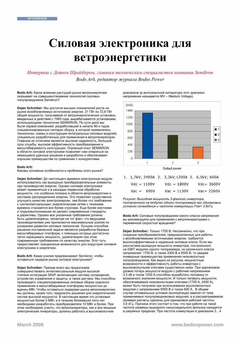
Силовая электроника для ветроэнергетики
Интервью с Деяном Шрайбером, главным техническим специалистом компании Semikron Bodo Arlt, редактор журнала Bodos Power
Bodo Arlt: Какое влияние растущий рынок ветроэнергетики оказывает на совершенствование технологий силовых полупроводников Semikron?
Dejan Schreiber: Мы достигли высших показателей роста на рынке возобновляемых источников энергии. 31 ГВт из 72,6 ГВт общей мощности, получаемой от ветроэнергетических установок, введенных в действие с 1993 года, вырабатывается установками, использующими технологии SEMIKRON. По сути дела мы были первой компанией, разработавшей в начале 90-х годов специализированную силовую сборку, в которой применялись технологии, схемы и конструкции интегральных силовых модулей, специально разработанные для применения в ветрогенераторах. Главным их отличием является высокая надежность, большой срок службы, высокая эффективность преобразования и масштабируемость конструкции. Огромный опыт SEMIKRON в области силовой электроники позволяет нам опираться на имеющиеся удачные решения и разработки и обеспечивает хорошие преимущества по сравнению с конкурентами.
Bodo Arlt: Каковы основные особенности и проблемы этого рынка?
Dejan Schreiber: До настоящего времени электронные модули использовались как выходные преобразовательные элементы при производстве энергии. Однако силовая электроника может применяться и в каскадах первичной обработки мощности, что особенно полезно в области ветроэнергетики и системах распределения энергии. Это позволяет существенно улучшить качество электроэнергии, тем более что требования к «интеллектуальным» энергетическим сетям с течением времени становятся все более строгими. Еще более жесткими и трудновыполнимыми их делают современные стандарты и директивы. Однако все указанные требования должны быть удовлетворены, несмотря на тот факт, что ведущими производителями уже прилагаются максимальные усилия по ускорению развития силовых технологий. Лучшим способом решения поставленной задачи является разработка базовых масштабируемых платформ, с помощью которых достаточно легко наращивать мощность, удовлетворяя при этом современным требованиям по качеству энергии. Этот путь предоставляет грандиозные возможности для индустрии силовой электроники и энергетики.
Bodo Arlt: Какие усилия предпринимает Semikron, чтобы оставаться лидером рынка силовой электроники?
Dejan Schreiber: Прежде всего мы продолжаем совершенствовать интеллектуальные модули высокой степени интеграции SKiiP, включающие систему охлаждения, устройство управления и защиты, а также датчики. Мы способны производить специализированные силовые сборки широкого применения и масштабируемые платформы мощностью до единиц МВт. Чтобы оставаться лидерами рынка ветроэнергетики мы должны, кроме того, предлагать решения для энергетических систем высокой мощности. В настоящее время это установки мощностью более 5 МВт, а в течение ближайших пяти лет необходимо разработать преобразователи 10 МВт и более. При этом необходимо учесть, что ветрогенераторы, как и все мощные электрические генераторы, должны работать в высоковольтном
диапазоне (в англоязычной литературе этот диапазон напряжения называется MV – Medium Voltage).
Рисунок: Выходная мощность 3-фазного инвертора, построенного на модулях одного типоразмера при одинаковых условиях охлаждения и частоте коммутации Fsw= 3.6кГц
Bodo Arlt: Силовые полупроводники какого класса напряжения вы рекомендуете для применения с ветрогенераторами с переменной скоростью вращения?
Dejan Schreiber: Только 1700 В. Несомненно, что при создании преобразователей, предназначенных для работы с возобновляемыми источниками энергии, требуются высокоэффективные и надежные силовые ключи. Если мы рассчитаем выходную мощность инвертора, построенного на IGBT модулях одного типоразмера, но различного класса напряжения: 1700 В, а также 3300 В и 6500 В, то увидим очевидные преимущества применения низковольтных полупроводников. Как видно из рисунка, мощностные возможности и эффективность работы инвертора с высоковольтными ключами существенно ниже. При одинаковом уровне потерь мощности модули с рабочим напряжением 3,3 кВ и током 1200 А способны выработать половину от возможного значения мощности. И только четверть мощности, обеспечиваемой низковольтными ключами (1700 А, 2400 А), может быть получена при использовании высоковольтных модулей с напряжением 6500 В и током 600 А. В общем случае оптимальные условия эксплуатации зависят от типа применяемых полупроводниковых модулей, а в рассматриваемом примере расчеты сделаны для одинаковой рабочей частоты 3,6 кГц. Причина этого состоит в том, что при работе на такой частоте размеры выходного синусоидального фильтра находятся в разумных пределах. При частоте коммутации в диапазоне 3…4
VIP INTERVIEW
www.bodospower.comMarch 2008

кГц, потери мощности на фильтре составляют примерно 15% от мощности инвертора. Однако даже при близких размерах фильтра, для построения высоковольтного инвертора на IGBT различного класса требуются совершенно разные схемные решения.
Bodo Arlt: Что в первую очередь отличает Semikron от других производителей?
Dejan Schreiber: Прежде всего, мы ориентированы на конечное применение. Наша компания разрабатывает и производит широкую номенклатуру полупроводниковых модулей, предназначенных для работы в конкретных схемах. Например, много лет назад мощные одиночные IGBT имели только 2 терминала (коллектор и эмиттер) и выпускались в двух исполнениях для применения в каскадах верхнего и нижнего плеча полумостового каскада. Мы понимали недостатки такого решения с самого начала, очевидно, что в инверторе напряжения, базовым элементом которого является полумост, силовые модули должны иметь раздельные DC и АС терминалы. Интеллектуальные силовые ключи SKiiP, конструкция которых была разработана более 15 лет назад, имеют силовые выводы для подключения звена постоянного тока и АС выхода, расположенные по разные стороны корпуса. При этом каждый полумост снабжен индивидуальными терминалами, позволяющими осуществлять их параллельное соединение с помощью простой шины. Этот конструктив в настоящее время широко используется другими производителями, и до сих пор никто не придумал ничего лучшего. Кроме того, колоссальный опыт SEMIKRON в ветроэнергетике позволил нам создать ряд интегральных силовых модулей, применение которых гарантирует как отличные показатели надежности, так и высокую эффективность. Примером является несколько семейств модулей IGBT без базовой платы, разработанных по SKiiP технологии прижимного контакта. Все тепловые связи в силовых ключах подобной конструкции осуществляются за счет многоточечного прижима, что позволяет обеспечить равномерное распределение тепла и низкое тепловое сопротивление. Безбазовые модули прижимного типа имеют гораздо более высокую стойкость к активному и пассивному термоциклированию, чем силовые ключи традиционной конструкции. Они обеспечивают предельно высокую плотность мощности и простоту параллельного соединения.
Bodo Arlt: Насколько глубоко Semikron участвует в работе над проектированием ветроэнергетических установок?
Dejan Schreiber: Вместе с заказчиком SEMIKRON участвует в работе над проектом, начиная с выдачи технического задания и до выпуска рабочей документации. Кроме того, мы обеспечиваем наших партнеров постоянной технической поддержкой.
Bodo Arlt: Как Вам видится будущее IGBT технологий применительно к солнечной энергетике и ветроэнергетике?
Dejan Schreiber: Сектор ветроэнергетики требует разработки модулей высокой степени интеграции и «интеллектуализации». Что касается солнечной энергетики, здесь Semikron работает в тесном контакте с производителями инверторов для солнечных термальных станций. Максимальная эффективность преобразования для таких устройств является главным экономическим аргументом для продвижения на рынке. Большая плотность тока и высокий к.п.д. обеспечивают минимальный срок окупаемости изделия.
Инверторы солнечных станций работают на высоких частотах, что необходимо для минимизации размеров фильтров. Диоды из карбида кремния (SiC) и MOSFET транзисторы в данном случае могут стать альтернативой кремниевым быстрым диодам и IGBT ключам, поскольку их использование позволяет снизить уровень динамических потерь. Только замена стандартных диодов на SiC в IGBT преобразователях позволяет уменьшить коммутационные потери почти на 30%. Кроме того, для такого специфического применения, как солнечные энергетические станции требуется разработка специальных конфигураций схем.
Bodo Arlt: Ожидаете ли Вы в будущем появления инверторов для ветроэнергетических установок в интегральном исполнении?
Dejan Schreiber: Определенно да, поскольку применение интегральных блоков обеспечивает высокую «гибкость» и масштабируемость изделия.
Bodo Arlt: Собирается ли Semikron шире использовать SiC технологии для ветроэнергетических применений?
Dejan Schreiber: Не в ближайшем будущем. На этом рынке требуются, прежде всего, сильноточные ключи, а инвестиции, необходимые для разработки достаточно мощных модулей на основе карбида кремния, пока экономически не оправданы.
Bodo Arlt: Кто из ваших конкурентов по вашему мнению способен бороться за лидерство?
Dejan Schreiber: Отмечу еще раз, что общая мощность ветроэнергетических установок, запущенных с 1993 года во всем мире, составляет 72.6 ГВт и в 43% из них используются технологии и компоненты Semikron. Производители ветрогенераторов нуждаются в преобразователе типа «all-in-one», содержащем силовые каскады, согласованную систему охлаждения, интегрированную схему управления, мониторинга и защиты. Мы способны предложить такое устройство и в этом наше главное отличие от конкурентов. Наличие всех указанных свойств у модулей серии SKiiP и их высокая стойкость к активному и пассивному термоциклированию обусловливает высокую потребительскую ценность компонентов данного типа для наших заказчиков. Интеллектуальные силовые ключи (IPM) SKiiP предназначены для использования в мегаваттном диапазоне мощностей, на сегодняшний день это одни из самых мощных IPM на рынке. В настоящее время большие возможности для нас представляет динамично развивающийся рынок ветроэнергетики в Азии. Правительство Китая планирует к 2020 году покрыть 10% потребности страны в электроэнергии за счет использования возобновляемых источников.
Bodo Arlt: Гн. Шрайбер, большое спасибо за то что нашли время ответить на наши вопросы. Мы с надеждой смотрим в будущее и понимаем, какие радужные перспективы открывает для нас рынок ветряной и солнечной энергетики.
www.semikron.com
Dejan Schreiber
Деян Шрайбер получил диплом с отличием по специальности «Электротехника» в Белградском университете в 1970 г. До 1988 года он работал в техническом институте имени Николы Теслы в Белграде в отделе Силовой электроники и Управления. В это же время он читал лекции и работал в качестве приглашенного профессора в университетах городов Белград и Новый Сад (Югославия), а также университете города Хараре в Зимбабве.
В 1989 г. Деян Шрайбер начал свою деятельность в компании СЕМИКРОН в Нюрнберге в качестве старшего технического специалиста. Его специализацией являются силовые преобразователи для ветрогенераторов с переменной скоростью вращения, высоковольтные привода асинхронных двигателей, привода высокоскоростных микротурбин, мощные источники бесперебойного питания, привода для электропоездов, троллейбусов и трамваев, транспортные средства с атарейным питанием, автоэлектроника и преобразователи для топливных элементов. [email protected]
VIP INTERVIEW
www.bodospower.comMarch 2008

关于电力电子在风力发电中应用的访谈
访赛米控高级应用经理Dejan SchreiberBodo Arlt, Editor BP
Bodo Arlt: 不断增长的风能市场会给赛米控的功率半导体开发带来什么样的影响?
Dejan Schreiber: 我们在可再生能源市场实现了大的增长度。自1993年以来,全球总风力发电装机容量为72.6 GW,其中31GW采用了赛米控的技术。事实上,我们在九十年代初提供了第一个用于风力发电的功率半导体解决方案。当时我们对一个专用于风力发电机的集成功率模块的技术和驱动器拓扑结构进行了研究,因为它运行可靠性高,服务预期寿命长,效率高且可扩展的设计。
我们对技术的长期跟踪,使得我们能够开发出先进的产品和设计。这给了我们一个超过竞争对手的良好开端。
Bodo Arlt: 这个市场所面临的挑战或选择是什么?
Dejan Schreiber: 直至目前为止,电力电子技术被用于电能生产的后端。但是,电力电子产品也可用于前端,例如在风力发电中,以及作为配电——在输电线路解决方案的前端和后端。由此,改进了电能质量。
配电对智能网格的要求正变得越来越严格。标准和审批使得需求更为复杂。所有这些需求都要得到满足,即使加快开发速度的压力已经增大。满足这一要求的 好方式是开发能够形成基础平台的产品,这些产品可以很容易被扩充,以应对不断增长的对功率等级的需求功率范围。这对电力电子产业是巨大的挑战。
Bodo Arlt: 赛米控提供什么样的解决方案以确保在风力发电市场保持领先地位?
Dejan Schreiber: 我们提供 SKiiP,一款包含了完美匹配冷却系统、栅极驱动器、电流传感器和保护电路的集成功率模块。我们还有兆瓦级的功率模块装配和扩展方案。然而,为了在风力发电市场保持领先地位,我们必须为更高功率的需求开发解决方案。这些需求中功率超过5 MW,5年内将达到10 MW。 与这些大功率发电机相比,风力发电机属于中压系统。
Bodo Arlt: 对于变速风力发电机,您推荐多大的半导体电压?
Dejan Schreiber: 1700 V。可再生能源的应用无疑需要高效率和得到验证的半导体。
运行配备尺寸相同但电压不同(1700 V(低压器件)、3300V和6500V)的IGBT模块的逆变器并模拟可获得的输出功率,可以看出中压IGBT显然不是一个经济的解决方案(见图1 )。输出功率的限制等于总功率损失。对于相同的功率损失, 3.3kV 1200A中压模块只能产生一半的可用功率。1.7kV 2400A和6.5kV 600A模块只能产生四分之一的可用功率。
根据电压水平调整运行条件。开关频率均为3.6 kHz,使用相同开关频率的原因是滤波器的尺寸。在3- 4 kHz,正弦滤波器的功率约为逆变功率的15%。这样,所有逆变器都有相似的滤波器尺寸和成本。这意味着,对于兆伏级设备,需要不同的逆变电路。
图 :Fsw= 3.6kHz时,相同模块尺寸和冷却条件下,三相IGBT逆变器的输出功率
Bodo Arlt: 是什么使得赛米控与其他模块供应商有所不同?
Dejan Schreiber: 我们是面向应用的。我们开发和生产便于在给定应用中使用的功率半导体。
举个例子,很多年前,巨型IGBT单开关模块只有两个端子(集电极和发射极),并且有两套,就像在镜子里一样。一个用于底部开关,一个用于顶部开
VIP INTERVIEW
www.bodospower.comMarch 2008
关。我们从一开始就意识这种解决方案的缺点。对于电压源逆变器,功率模块必须是一个配有单独DC和AC端子的半桥。SKiiP的布局,从诞生至今已超过15年,在模块的一侧有DC端子,另一侧有AC端子,并且有几个平行端子。现在其他供应商也使用这种设计,并没有得到突破。
此外,我们在风力发电领域的经验使得我们可以整合解决方案,并保证可靠性和高效率。
例如,采用SKiiP®技术的无基板模块,该模块基于热压触点。基板被去除了,集成的压力系统在一些均匀散布的点上将DCB压在散热器上。这种压接技术确保了小热阻,出色的耐高低温循环能力并增加了功率密度。另外,如果需要大电流,可以很容易地并行开关几个模块。
Bodo Arlt: 赛米控直接参与 终用户风力发电应用的程度如何?
Dejan Schreiber: 从 初的规格到设计阶段,我们与客户紧密地配合,并为他们提供本地服务和支持。
Bodo Arlt: 您如何看待用于太阳能逆变器和风力发电应用的IGBT栅极驱动技术的未来?
Dejan Schreiber: 在风力发电应用中,需要更加智能的驱动电路,这些电路中集成度是主要驱动力。
至于太阳能逆变器, 赛米控正与太阳能逆变器制造商密切合作。对于 终市场来说,太阳能逆变器的效率是其中一个主要的卖点,由于其较短的回报期和较高的电流供应。太阳能逆变 器运行在高开关频率下,以减少滤波器的尺寸。碳化硅二极管和MOSFET是标准硅续流二极管和IGBT的替代解决方案,以减少开关损耗。配备了碳 化硅和IGBT的逆变器已经可以将开工损耗降低30 %。很多时候,模块中采用客户特定的拓扑结构。
Bodo Arlt: 您期望单片逆变器被用于未来的风力发电应用中吗?
Dejan Schreiber: 那是肯定的。单片组件将带来有更多的灵活性。
Bodo Arlt: 我们能期望在赛米控风力发电解决方案中看到更多的碳化硅器件吗?
Dejan Schreiber: 近期还不会。由于需要大电流,投资和净计量之间的权衡使得它在经济上是不可行的。
Bodo Arlt: 您认为你们的哪些竞争对手会有推动这种领导地位的竞争?
Dejan Schreiber: 再看一下,自1993年以来,已安装的总风力发电装机容量为72.6 GW,其中43 %的风力发电机采用了赛米控的技术。风力发电机制造商需要一体化的功率解决方案,包括匹配的冷却系统、栅极驱动器、电流传感器以及集成保护功 能。这里,我们有不同的竞争优势。我们的顾客从随时可用的SKiiP模块中获益,该模块提供优秀的负载与温度循环能力。
该IGBT子系统适用于兆瓦级电力应用,这也正是为什么它是市场上 强大的IPM之一。
目前,亚洲不断增长的动态风能市场也给我们带来新的机遇。到2020年,中国政府计划其能源需中的10%由可再生能源提供。
Bodo Arlt: Dejan Schreiber先生,非常感谢您抽出宝贵的时间接受我们的采访。我们期待着功率模块在风力发电和太阳能应用中有一个美好的未来。
www.semikron.com
Dejan Schreiber
Dejan Schreiber 先生1970年 获得贝尔格莱德大学电气工程专业荣誉硕士学位。此后至1988年,他一直在贝尔格莱德的尼古拉 • 特斯拉电子技术研究所的电力电子与控制部工作。与此同时,他也是南斯拉夫贝尔格莱德和诺维萨德以及津巴布韦哈拉雷几所大学的讲师和客座教授。
1989年他加入德国赛米控(纽伦堡)公司,任高级应用经理。他的专长包括研究变速风力发电机的电力电子变换器和用于交流电动机驱动的中压驱动器设计,高速微型燃气轮机和变速机组,用于UPS应用的新型电路,列车中的牵引应用,无轨和有轨电车,电池驱动汽车,汽车驱动和燃料电池的应用。
VIP INTERVIEW
www.bodospower.comMarch 2008