electronic paint-mixing scales for zone 1 - sartorius · electronic paint-mixing scales for use in...
TRANSCRIPT

98648-014-43
Installation Instructions
Sartorius PMA.Quality PMA 7501-X|PMA 7501-X00V1|PMA 7501-X00WElectronic Paint-mixing Scales for Zone 1
98648-014-43

2
General View of the PMA 7501-X (PMA.Quality)Electronic Paint-mixing Scales for Use in Zone 1 Hazardous Areas
1 Display and control unit 2 Q key (On/Standby)3 R key: Upwards4 S key: Downwards5 U key: Zero/Tare6 I key (TOGGLE) With the PMA 7501-X, you can toggle
to two decimal places – from 0.05 g to 999.95 g – or toggle between – “g” and “p” – parts per pound, depending on the menu settings
7 K factor key (FORMULATION) for paint-mixing applications
8 c key (Clear) and [REC] key for paint-mixing applications
9 L key [ENTER] and [MEM] key for paint-mixing applications
10 Display11 Weighing pan12 Interfaces (D-Sub plug, 9-contact)13 Connection to AC power14 Grounding terminal 15 Column16 Joint
The following symbols are used in these instructions:
§ Indicates required steps$ Indicates steps required only under
certain conditions> Describes what happens after you have
performed a particular step– Indicates an item in a list! Indicates a hazard
1234567
89
11
12
15
10
1314
16

3
Contents
General View of the Equipment . . . . . . 2Intended Use . . . . . . . . . . . . . . . . . . . 3Warnings and Safety Precautions . . . . 3Getting Started . . . . . . . . . . . . . . . . . . 6Operating the Equipment . . . . . . . . . . 8Applications . . . . . . . . . . . . . . . . . . . . 10Calibration/Adjustment . . . . . . . . . . . . 13Menu Settings . . . . . . . . . . . . . . . . . . 14Troubleshooting . . . . . . . . . . . . . . . . . 19Care and Maintenance . . . . . . . . . . . . 20Recycling . . . . . . . . . . . . . . . . . . . . . . 21Specifications . . . . . . . . . . . . . . . . . . . 22Interface Port . . . . . . . . . . . . . . . . . . . 22Accessories . . . . . . . . . . . . . . . . . . . . . 23Declaration of Conformity . . . . . . . . . . 24Control Drawing . . . . . . . . . . . . . . . . . 29Verification of Intrinsic Safety . . . . . . . 32
Intended Use The PMA7501-X (Quality) has been
specially designed for use in the paint-mixing applications. This scale can be controlled by a computer connected to the interface port.
Note: – Read the installation and operating
instructions carefully before connect-ing the PMA7501-X and putting it into operation.
– The application examples and menu settings described in these installation instructions are not valid for PMA7501-X00W.
Note: Improper use or handling can result in
property damage and/or personal injury. Only qualified personnel may install and operate the equipment. Make sure you observe the warning and safety informa-tion in its entirety during installation and operation, as well as while perform-ing maintenance and repair work on the equipment. The standards, regulations, occupational safety requirements and environmental protection laws valid in your country must be observed. It is important that all personnel using the equipment understand this warning and safety information, and have access to the relevant documents at all times. Furthermore, the warning and safety information supplied with any electrical equipment connected, such as peripheral devices, must be observed as well. The warnings and safety precautions may have to be supplemented by the equip-ment operator. All operating personnel must be informed of any additions to these instructions. Make sure the equip-ment is accessible at all times.
General Provisions for Installing the PMA7501-X
PMA7501-X models meet the require-ments defined in EC Directive 94/9/EC for equipment group II, category 2G and are marked in accordance with the KEMA05 ATEX1247X EC type-exami-nation certificate. In addition, they are approved for hazardous (classified) loca-tion Class I, Division 1, Groups C,D, and Class I, Zone 1, Groups IIA and IIB, in the United States and in Canada, respectively. Furthermore, PMA7501-X models meet the EC Directives for electromagnetic compatibility and electrical safety (please see the Declaration of Conformity in these installation instructions.)
Warnings and Safety Precautions

4
- The area of use for the PMA7501-X model is defined in the type-examination certificate. All restrictions listed in the type-examination certificate must be strictly observed. Operating the PMA7501-X model beyond the restric-tions indicated is not permitted, and is considered use of the equipment for other than its intended purpose.
Any installation work that does not con-form to the instructions in this manual will result in forfeiture of all claims under the manufacturer’s warranty. If you use the equipment in a hazardous area out-side Germany, you must comply with the national electrical code and safety regulations applicable in your country (e.g.: EN60079-14). Ask your supplier for information on the legal regula-tions applicable in your country. For the USA and Canada, please refer to Control Drawing 35958-000-07-A4.
– If the equipment housing is opened by anyone other than persons authorized by Sartorius, this will negate its conformity with regulations governing its use and result in forfeiture of all claims under the manufacturer’s warranty.
– Installation of the PMA7501-X in a potentially explosive atmosphere must be performed by a certified electrician who is familiar with both the assembly, start-up and operation of both the system and the relevant guidelines and regulations, and has the required qualifications for performing the installation. If you need assistance, contact your Sartorius dealer or the Sartorius Service Center.
– Avoid static electricity. Connect an equi-potential bonding conductor. Disconnecting equipotential bonding conductors is not permitted. The bore hole is marked by a “ground” symbol. If a bore hole is provided, use a stainless steel
screw and nut to connect the grounding conductor. The wire used for the ground-ing conductor should have a cross-sec-tional diameter of at least 4 mm2 and have a suitable ring lug attached. Connect all equipment, including peripheral devices, to the equipotential bonding conductor.
– Do not expose the scale to extreme temperatures, aggressive chemical vapors, moisture, shocks or vibrations. Exposure to excessive electromagnetic dis-turbance can cause the readout value to change. Once the disturbance has ceased, the instrument can be used again in accordance with its intended use.
– The equipment must be used indoors. – To ensure safety, disconnect the equip-
ment from power before connecting or disconnecting the cables or electronic peripheral devices.
– If you use cables purchased from another manufacturer, check the pin assignments in the cable against those specified by Sartorius before connecting the cable to Sartorius equipment, and disconnect any wires that are assigned differently. The operator shall be solely responsible for any damage or injuries that occur when using cables not supplied by Sartorius.
– When connecting the scale to the power supply, the laws valid in your country must be observed. If you should have any questions, please contact your supplier or Sartorius Customer Service for information on the legal regulations applicable in your country. The scale must be installed by a certified technician to avoid forfeiture of all claims under the manufacturer’s warranty.
– To avoid generating static electricity (e.g., when using the in-use dust cover), connect the equipotential bonding conductor.
– The equipment is protected against penetration by solid foreign objects.

5
For the User– Always make sure the equipment is
disconnected from AC power before performing any installation, cleaning, maintenance or repair work on the scale.
– If you see any indication that the scale cannot be operated safely (for example, due to damage), turn it off and lock it in a secure place or otherwise prevent use of the equipment for the time being.
– Chemicals (e.g., gases or dusts) that can corrode and damage the inside or outside of the device must be kept away from the equipment. Handle the equipment and any accessories in accordance with the IP rating (IP65 or higher) and EN 60529.
– The casing on all connecting cables, as well as the casing on wires inside the equipment housing, is made of PVC. The casing of the power cable is made of rubber.
– Do not expose the scale to aggressive chemical vapors or to extreme tempera-tures, moisture, shocks, or vibration. The allowable operating temperature range during operation is 0°C to +40°C +(32°F to +104F). Make sure the place of installation is adequately ventilated to prevent build-up of excessive heat.
– Use original Sartorius spare parts only.– Never use a hammer to close the lid of a
paint can while it is still on the weigh-ing pan. Otherwise, you will damage the weighing system.
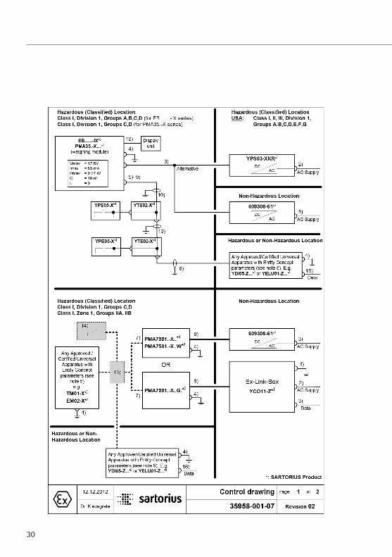
PMA7501-X Designed for Use in Zone 1 Hazardous Areas
Please refer to the drawings unter “Verification of Intrinsic Safety” for details.

6
Getting Started
§ Remove the scale from its packaging.
§ After unpacking the scale, check it immediately for any visible damage as a result of rough handling during shipment.
Equipment Supplied – Scale– Weighing pan– Power supply– 2+ protective plugs (in the column)
Setting Up the Scale Choose a suitable place to set up the scale. Avoid
exposure to drafts, heat, moisture and vibration. Make sure to read the instructions carefully before connecting the scale to AC power.
! Observe the safety instructions and warnings in this manual.
§ Place the weighing pan on the scale.
°C

Connection to AC Power The equipment is energized by the power supply
provided. Make sure that the voltage rating printed on the power supply is identical to your local AC power rating. When connecting the scale to the power supply, the laws valid in your country must be observed. If you should have any questions, please contact your supplier or Sartorius Customer Service for information on the legal regulations applicable in your country. Use only genuine Sartorius power supplies. The use of power supplies from other manufacturers, even if these units have a registered approval rating from a national testing laboratory, requires the approval of a certified technician.
§ Insert the right-angle plug into the IEC jack (13) on the scale
§ Plug the power supply into an electrical AC power outlet
! Observe the safety instructions and warnings in this manual
§ Ground the scale. Connect the cable to the grounding terminal (14).
7

Operating the Equipment
Weighing with One Decimal PlacePlace an empty paint can on the weighing pan.Press the U key (5). The display shows “0.0 g.”Pour in the first component, and read off the weight as soon as the stability symbol appears; in this case, “g.”Pour in additional components until the desired weightof your formula is reached.Remove the filled paint can from the weighing pan.
Never use a hammer to close the lid of a paint can while it is still on the weighing pan.Otherwise, you will damage the weighing system.
8
Turn on the scale using the Q key (2).
After the scale has been turned on, it will automati-cally run a self-test. At the end of this test, 0.0 g is displayed.
If a different readout is displayed, zero or tare the scale using the U key (5).

9
Weighing with Two Decimal Places
Note: To weigh using two decimal places, you must first adapt the settings (refer to the chapter entitled “Menu Settings”)
Press the I key (6). The display shows “0.00 g.”
Place an empty paint can on the weighing pan (11).
Press the U key (5). The display shows “0.00 g.”
Pour in the first component: 205.50 g.Read off the weight as soon as the stability symbol appears; in this case, “g.”
Pour in additional components until the desired weight of your formula is reached.Remove the filled paint can from the weighing pan.
Important Note:If you zero the display by pressing the tare key, and then press the I key (6) to toggle to the second decimal place with a resolution of 0.05 g, you can continue weighing up to 999.95 g.For weights exceeding 999.95 g, only one decimal place will be displayed.
Never use a hammer to close the lid of a paint can while it is still on the weighing pan.Otherwise, you will damage the weighing system

Applications
Formulation Mode (Calculation by a Factor)This mode enables you to weigh in amounts that are smaller or larger than that of your basicformula for a specific paint color (e.g., 250 ml of a 1-l formula).You can select various factors (amounts) by pressing the K formulation key (7):0.25 0.5 0.75 1.0 1.5 2.0 2.5 3.0 3.5 4.0 4.5 5.0.
By pressing the R key (3): upwards or S key (4): downwards, you can alter the value – in 0.1 increments, as of factor 1.0 or – 0.01 increments, from factor 0.25 to 1.0.
Important Note:The flashing arrow n on the display means that the weight value shown is not verified for use in legal metrology (not legal for trade).
Example:As you pour in the components of your formula, the weight is displayed in “g.” Let’s suppose you want to weigh only 250 ml of a basic formula that is for a total amountof 1 L. With the recalculation mode, you do not need to manually recalculate the individualcomponents.The basic formula for 1 liter is:
250 g green paint + 250 g red paint + 500 g blue paint Total: 1000 g
10
1. Place the empty paint can on the weighing pan and tare (zero the display).
2. Press the K formulation key (7) several times to select the conversion factor “.25” used in this example.

11
We have come to the end of our example. According to the display, exactly 1,000 g was poured in, but the paint can actually contains only 250 g by weight according to the factor you selected, .25. Follow the same procedure for any other conversion factor or to convert a 1-gallon formula into quarts.
Weighing Using the Recalculation Mode Let’s suppose that you poured in too much of one color component for a given formula (e.g., one consisting of 4 components). In addition, let’s assume that you previously poured in all of the other amounts exactly according to each of the values you entered and stored by pressing the L key [MEM] (9). Press the S key (4) to start the recalculation program. “C” will begin flashing on the display. To correct the weight displayed to the same value you entered for the given formula, either scroll upwards using the R key (3), or downwards using the S key (4). When you then press the L key [MEM] (9), the scale will automatically calculate and display the amounts of paint in “g” to add for each of the other components that you already poured in. This mode thus ensures that the total result of your formula for these components will be correct. After pouring in these amounts, you can continue to add the remaining components of your formula.
Important Note:You can correct an incorrect amount any number of times. However, the total (liter) quantity in the paint can will increase each time you correct a component. Therefore, press the c key (8) to check how much the total quantity (in liters) will be. (“C” = correction factor)
The flashing arrow n in the display means that the weight value shown is not verified for use in legal metrology (not legal for trade).
3. “.25” is displayed next to the weight
4. Slowly pour in the first component, “250 g” of green paint, until the display shows “250 g.”
5. Pour in the second component, “250 g” of red paint, until the display shows “500 g.”
6. Pour in the last component, “500 g” of blue, until “1000 g” is displayed.

3. Pour in the first component. + 50.0 g
2. Press the U key (5) 0.0 g
12
Example (cumulative):
1. Place an empty paint can on the weighing pan (11). + 118.0 g
4. Press the L key [MEM] (9). STO 01
5. Pour in the 2nd component. + 110.0 g
6. Press the L key [MEM] (9). STO 02
7. Pour in the 3rd component. + 203.0 g Oops! You poured in too much! The correct weight for the formula is 200.0 g.
8. Press the y key (4) to start the recalculation mode. A “C” (= correct).
9. Press the y key (4) several times to correct the value to: + 200.0 g
10. Press the L key [MEM] (9). COR 01
11. 1. Add the first component. “C1” is displayed. –1.5 g
12. Pour in paint until 0.0 g is displayed. 0.0 g
13. Press the L key [MEM] (9) COR 02
14. Add the second compo-nent. “C2” is displayed. –2.0 g
15. Pour in paint until the value 0.0 g is obtained. 0.0 g
16. Press the L key [MEM]. The scale will automatically return to the formulation program. “C” disappears. + 200.0 g.
17. To check the prospective total weight, press the c key (8) [REC]. “C” = Correction factor; in this example, 1.02. (Total formula weight + correc-tion factor = total weight)
18. Add the fourth component +1000.0 g We have come to the end of our example.

13
Calibration/Adjustment
You can calibrate/adjust the scale by pressing the U key (5).
Calibration weight: 5,000 g; accuracy: + 0.075 g.
After connection to AC power and before each calibration/adjustment, allow the scale to warm up for approx. 30 min.
Hold down the U key (5) for 2 sec. When 5000 is displayed, release the key.
Center the calibration weight on the weighing pan (11).Calibration/adjustment is performed automatically. After calibration and adjustment, remove the weight.
Menu Settings
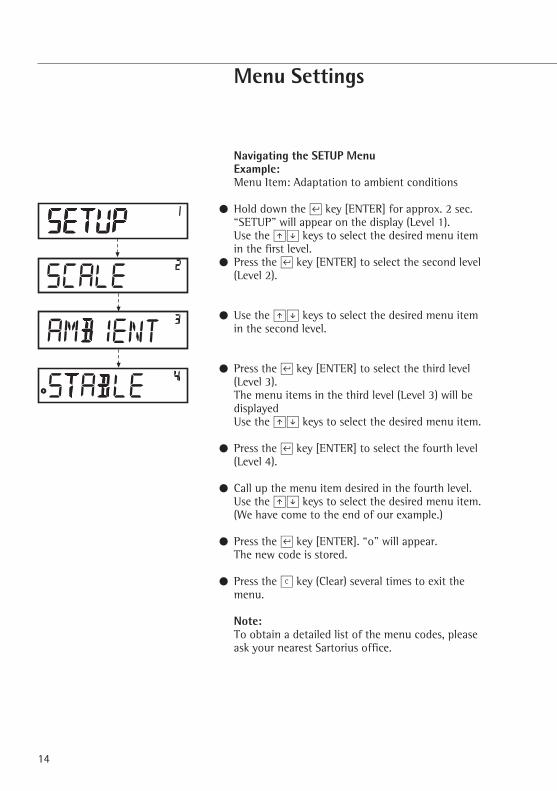
Navigating the SETUP Menu Example: Menu Item: Adaptation to ambient conditions
§ Hold down the L key [ENTER] for approx. 2 sec. “SETUP” will appear on the display (Level 1). Use the RS keys to select the desired menu item in the first level.
§ Press the L key [ENTER] to select the second level (Level 2).
§ Use the RS keys to select the desired menu item in the second level.
§ Press the L key [ENTER] to select the third level (Level 3). The menu items in the third level (Level 3) will be displayed Use the RS keys to select the desired menu item.
§ Press the L key [ENTER] to select the fourth level (Level 4).
§ Call up the menu item desired in the fourth level. Use the RS keys to select the desired menu item.
(We have come to the end of our example.)
§ Press the L key [ENTER]. “o” will appear. The new code is stored.
§ Press the c key (Clear) several times to exit the menu.
Note:To obtain a detailed list of the menu codes, please ask your nearest Sartorius office.
14

15
Important Menu Settings§ Hold down the L key [ENTER] for approx. 2 sec. “SETUP” will appear on the display (Level 1). Level 1
SETUP
Language Settings Level 1 Level 2 Level 3 Level 4
LANGUAGE § R key: select “LANGUAGE” § L key: press [ENTER] o GERMAN § RS keys: select a language ENGLISH § L key: [ENTER]: “o” will appear, FRENCH the desired setting is defined. ITALIAN § c key (Clear): press several times to etc. exit the menu.
I – Activating the Toggle Key; Configuring (Basic Setting) After the toggle key, I, has been activated, you can individually configure it with either 1 or 2 decimal
places, as well as with grams or PT./PD. Level 1 Level 2 Level 3 Level 4
SETUP § Press the L key [ENTER] APPLICATION § RS keys: select “APPLICATION” § L key: press [ENTER] Program § RS keys: select “PROGRAM” WIEIGH. § L key: [ENTER], o TOGGLE RS keys: select “TOGGLE”. § Press the L key [ENTER]; “o” appears: the desired setting is defined. § Press the c key (Clear) several times to exit the menu
Assigning a Function to the I Toggle Key: 0.0 g / 0.00 g, or g / PT./PD. Level 1 Level 2 Level 3 Level 4
SETUP § Press the L key: [ENTER] APPLICATION § RS keys: select “APPLICATION” UNIT § L key [ENTER]: select the S key “UNIT,” press L key [ENTER]. PT./PD. § RS keys: select “GRAMS” o GRAMS § Press the L key [ENTER]; “o” appears: the desired setting is defined. DECIMALS § RS keys, select “DECIMALS” STANDARD § Press the L key, select setting o POLYRANGE § Press the L key [ENTER]; “o” appears Press the c key (Clear) to exit the menu

Toggling Decimal Places (Standard = 1 decimal place PolyRange = 2 decimal places) Toggling Units (Grams or PT./PD.)
These settings are active when the scale is switched on. Level 1 Level 2 Level 3 Level 4
SETUP § Press the L key [ENTER] SCALE § Press the L key [ENTER] DECIMALS § RS keys: select “DECIMALS” § Press the L key [ENTER] o STANDARD § RS keys: select “STANDARD” POLYRANGE § Press the L key [ENTER]; “o” appears: UNIT the new code has been set. o GRAMS § Press the c key (Clear) several times PT./PD. to exit the menu
Activating the “LOCK” Function “ ” By activating the “LOCK” function, you can protect the scale from inappropriate use. When the
“LOCK” function is activated, the scale shows weight values on the readout only when communica-tion with the PC is active. If data transmission is interrupted, the lock symbol will be displayed. The scale will automatically be locked, preventing further weighing operations. The “LOCK” function is configured in the “EXTRAS” menu.
Level 1 Level 2 Level 3 Level 4
SETUP § Press the L key [ENTER] EXTRAS § RS keys: select “EXTRAS” § Press the L key [ENTER] LOCK § RS keys: select “LOCK” § Press the L key [ENTER] OFF § Select “ON” using the RS keys o ON Confirm with the L key § Press the c key (Clear) several times to exit the menu
Entering a Password In addition to activating the “LOCK” function, the user may also enter a password. Should the user wish to deactivate the “LOCK” function by pressing the “OFF” key, he must first
enter the valid password. The password is comprised of a 6-character numeric code. Use the RS keys to call up numbers (0 to 9). Six dashes (------) will appear in the display. The first dash will “blink” in the display. Select a number (0 to 9) using the RS keys, press the L key [ENTER] to save the number. The second dash will start to “blink.” Repeat the aforementioned process. Should you wish to assign a “blank space” to one of the six characters, simply press the L key [ENTER] when the dash begins to blink.
16

17
Note: Keep the numeric code in a safe place.
The scale can only be accessed by entering the correct code. Level 1 Level 2 Level 3 Level 4
INPUT § RS keys: select “INPUT” PASSWORD § Press the L key [ENTER] § Press the L key [ENTER] PW..NEW § RS keys: select “PW.NEW” -------- § Enter the numeric code: press the L key [ENTER]. § Press the c key (Clear) several times to exit the menu
Changing the Password Should you wish to change the password, you must first correctly enter the old password under
“Password.” “PW.OLD” will be displayed. Following the correct input, “PW.NEW” will automatically appear. You can now enter a new password, or confirm each blinking dash by pressing the L key [ENTER]. Blank spaces are then displayed.
Level 1 Level 2 Level 3 Level 4
INPUT § RS keys: select “INPUT” PASSWORD § Press the L key [ENTER] PW.OLD § Press the L key [ENTER] -------- § Enter the old password “PW.OLD” PW.NEW § “PW.NEW” will appear when the old password is correctly entered -------- § Enter the numeric code: press the L key [ENTER] § Press the c key (Clear): reset the menu You can now deactivate the “LOCK” function. SETUP § Press the L key [ENTER] EXTRAS § RS keys: select “EXTRAS” § Press the L key [ENTER] LOCK § RS keys: select “LOCK” § Press the L key [ENTER] o OFF § RS keys: select “OFF”, confirm with the ON L key [ENTER] § Press the c key (Clear) several times to exit the menu

Setting “TEXTS” in the Display, “LONG” or “SHORT” Either short or long display prompts for operator guidance can be shown. Level 1 Level 2 Level 3 Level 4
SETUP § Press the L key [ENTER] EXTRAS § RS keys: select “EXTRAS” § Press the L key [ENTER] TEXTS § RS keys: select “TEXTS” § Press the L key [ENTER] LONG § RS keys: select “SHORT”, o SHORT confirm by pressing the L key. § Press the c key (Clear) several times to exit the menu
Resetting the Scale: “RESET” If necessary, you can reset the scale to factory settings.
Note: If a password was activated, the correct password must first be entered.
Level 1 Level 2 Level 3 Level 4
SETUP § Press the L key [ENTER] RESET § RS keys: select “RESET” § Press the L key [ENTER] MENU § RS keys: select “MENU”. § Press the L key [ENTER] YES § Use the RS keys to select “YES” o NO § Press the L key [ENTER]; “o” will appear: the new code is set § Press the c key (Clear) several times to exit the menu
Setting Codes
Under the setting “CODES,” the menu items are displayed in code 1.1.1.1. Level 1 Level 2 Level 3 Level 4
LANGUAGE § R key: select “LANGUAGE” § Press the L key [ENTER] GERMAN § RS keys: select “CODES” etc. § Press the L key [ENTER]; “o” will appear: the new code is set o CODES § Press the c key (Clear) several times to exit the menu.
Note:To obtain a detailed list of the menu codes, please ask your nearest Sartorius office.
18

19
Troubleshooting
Problem Cause SolutionNo segments appear – No AC power available – Check the AC power supply on the weight displayWeight display shows – The weighing pan is – Position the weighing pan “Low” is not in placeWeight display shows – The load on the pan – Unload the scale “High” exceeds the scale’s capacity The weight readout – Unstable ambient conditions – Set up the scale in another area changes constantly – Too much vibration or – Access the menu to select the scale is exposed to draft the appropriate code to adapt
the scale to the particular weighing environment (refer to “Menu Settings”)
The weight readout – The paint component does – Tare prior to weighing is obviously wrong not have a stable weight – The scale was not tared before weighingNo weight value is – Data communication between – Access the menu settings to shown and the lock scale and PC has been deactive the “Lock” function symbol is active interrupted and the “Lock” – Check the connection function is active in the scale
20
Care and Maintenance
Cleaning! Do not use any aggressive cleaning
agents (solvents or similar agents), con-centrated acids or pure alcohol.
$ Make sure that no liquid penetrates the scale housing
$ Clean the scale using either a paint brush or a dry, soft and lint-free cloth.
Storage and Shipping Conditions$ To ensure safe shipment, your scale has
been packaged using environmentally friendly materials. You should retain these materials in case you need to package your scale for storage or return shipment.
$ Storage temperature: –20°C to +75°C$ Permissible moisture level for storage of
the packaged scale: 90% max.$ Read and follow the instructions given in
the section entitled “Safety Inspection.”
Safety Inspection Safe operation is no longer ensured
when:– There is visible damage to the power
supply– The equipment no longer functions
properly– The equipment has been stored for
a relatively long period under unfavorable conditions
– The equipment has been exposed to rough handling during shipment
§ Observe the warning and safety information
In this case, notify your nearest Sartorius Service Center or the International Tech-nical Support Unit based in Goettingen, Germany. Maintenance and repair work may only be performed by service techni-cians who are authorized by Sartorius and who have access to the required service and maintenance manuals and have attended the relevant service training courses.
! The seals affixed to this equipment indi-cate that only authorized service techni-cians are allowed to open the equipment and perform maintenance work so that safe and trouble-free operation of the equipment is ensured and the warranty remains in effect.

21
The packaging is made from environmentally-friendly materials that can be used as secondary raw materials. If you no longer need this packaging, bring it to your local recycling and waste
disposal facility according to the regula-tions applicable in your country. In Germany, you can dispose of this material using the VfW dual system (contract number D-59101-2009-1129). The equipment, including accessories and batteries, must not be disposed of in general household waste, and must be recycled similar to electrical and electronic devices. For further information about disposal and recycling options, please contact your local service staff. The partners listed on the following website can be used for disposals within the EU:
1) Go to http://www.sartorius.com.
2) Select the summary under “Service.”
3) Then select “Information on Disposal.”
4) Addresses for local Sartorius disposal contacts can be found in the PDF files given on this webpage.
h Sartorius will not take back equipment contaminated with hazardous materials (ABC conta-mination) either for repair or disposal.
Insert heading: “Service Address for Disposal” Please refer to our website (www.sartorius.com) or contact the Sartorius Service Department for more detailed information regarding repair service addresses or the disposal of your device.
Recycling

22
Specifications
Model PMA7501-X | -X00V1 | -X00WWeighing range g 999.95/7500Readability g 0.05/0.1Tare range (subtractive) g -999.95/-7500Max. linearity g < ±0.2Stability range digit 0.25 to 4Moisture-proof rating F Non-condensingAllowable ambient operating temperature range °C 0 to +40Weighing pan d mm 233Scale housing (W + D + H) mm 233 + 329 + 391Net weight, approx. kg 3.3Calibration weight kg 5, class F2 or betterPower consumption VA Average: 8; maximum: 16Interface RS-232C
– Format 7-bit ASCII, 1 start bit,1 or 2 stop bits– Parity Even, odd or no parity– Transmission rates 1200 to 38,400 bit/s– Handshake mode Software, hardware or none
Interface Port Pin Assignment 9-contact interface port Pin 2: (RXD) Receive Data Pin 3: (TXD) Transmit Data
Pin 4: (DTR) Data Terminal Ready Pin 5: (GND) Ground
Pin 6: BPI bridge Pin 8: (CTS) Clear to Send
Note: Only for connection to a certified intrinsically safe circuit (see Verification of Intrinsic Safety).

23
Accessories
Order no.:In-use dust cover YDC01PMA
EX power suppliesEC 609308-011UK 609308-211USA/CDN 609308-61

24

25

26

27

28

29
30

31

32
Verification of Intrinsic Safety1Blatt
Sheet
3vonof
Maßstab /Scale
---
PMA7501.-X.... /
Ausgabe / Revision
00FreigabeReleased by
GeprüftReviewed by
ErstelltWritten by
10.01.06
10.01.06
10.01.06
Date
Klausgrete
Klausgrete
Klausgrete
NameMaterial
35958-741-60-A4
Bennenung / Title
Änderung / Alteration---
Zeichnungs-Nr. / Drawing number
Hazardous areaZone 1Gas: IIB T4
Vi 12.6 VIi 230 mAPi 2.9 WCi 365 nFLi 0
Non-hazardous area
Power Supply and PA Connection (EquipotentialBonding Conductor)
(230 Vac)
Vo 12.6 VIo 230 mAPo 2.9 WCo 575 nFLo 420 µH
(230 Vac)
(100 - 240 Vac)
Vi 8.7 VIi 185 mAPi 1.61 WCi 5.6 µFLi 0
Vo 8.7 VIo 185 mAPo 1.61 WCo 10 µF (for IIB)Lo 5 µH (for IIB)
Sartorius cable; permanentlymounted on the power supply(max. length: 100m)
Sartorius cable; permanentlymounted on the power supply/Ex-link box (max. length: 100m)
Alternativeconnection
PMA7501.-X..PMA7501.-X..W
II 2 G EEx ib IIB T4
PMA7501.-X..G.
II 2 G EEx ib IIB T4
9-pin maleconnector
3-pin maleconnector
YPS05-Z.PPower supply
II (2)G [EEx ib] IIB / IIC
YCO11-ZEx-link box
II (2)G [EEx ib] IIB
609308-..1Power supply
II (2)G [EEx ib] IIC
Equipotentialbonding
conductor
Equipotentialbonding
conductor

33
Verification of Intrinsic Safety2Blatt
Sheet
3vonof
Maßstab /Scale
---
PMA7501.-X.... /
Ausgabe / Revision
00FreigabeReleased by
GeprüftReviewed by
ErstelltWritten by
10.01.06
10.01.06
10.01.06
Date
Klausgrete
Klausgrete
Klausgrete
NameMaterial
35958-741-60-A4
Bennenung / Title
Änderung / Alteration---
Zeichnungs-Nr. / Drawing number
RS-232 Data Output Port
Hazardous areaZone 1Gas: IIB T4
Non-hazardous area
RS-232 Data output port1
Vi 12.6 V 2 Vo 12.0 V 2
25.2 V 3 24.0 V 3Ii 330 mA* Io 125 mAPi any Po 373 mWCi 1 nF Co 9 µF 2
0.93 µF 3Li 0 Lo 8 mH
Z966 1 in YDI02-Z..
Vo 12 V 2
24 V 3
Io 328 mA *Po 0.96 W *Co 1.41 µF 2
125 nF 3Lo 300 µHLo/Ro 36 µH/ohm 2
36 µH/ohm 3
YDI05-Z.. 1
Vo 12.4 V 2 Vi 12.6 V 2
24.8 V 3 25.2 V 3Io 260 mA * Ii anyPo 800 mW * Pi anyCo 1.24 µF 2 Ci 0
112 nF 3Lo 400 µH Li 0Lo/Ro 44 µH/ohm 2
22 µH/ohm 3
YCO01-Y 1
Vo 11.8 V 2 Vi 12.6 V 2
23.6V 3 25.2 V 3Io 123 mA * Ii 131mAPo 361 mW * Pi anyCo 1.5 µF 2 Ci 0.5 nF
129nF 3Lo 2 mH Li 0.8 µHLo/Ro 98 µH/ohm 2
98 µH/ohm 3
YDI05-Z.. Interface converterII (2) GD [EEx ib] IIC or
Z966 Zener barrier 4
in YDI02-Z..: II (2) G [EEx ib] IIC or
YCO01-Y Interface converter 6
II (2) GD [EEx ib] IIC orII 3 (2)GD EEx nR[ib]IIC T4
Remarks:1: Combined circuits2: Measured against ground3: Between signal lines4: BAS01ATEX7005; II (1) GD [EEx ia] IIC; parameter(s)
converted5: Option; passive wiring only6: Approved for Zones 2 and 22 hazardous areas with gas:
IIC / IIB T4 and dust: T80°C; only when USB port issealed and restricted breathing is maintained.
*: Ohmically limited
6-wire standard cable wire diameter up to 0.5≤ (minimum34 ohm/km) with max. 250 nF/km and max. 750µH/km,yielding max. 22 µH/ohm.
Cable length (flexible installation) is restricted, however, tounder 25 m in accordance with the RS-232 specifications.
T-connector5Foot actuatedswitch5
PMA7501.-X....PMA7501.-X..W
II 2 G EEx ib IIB T4
9-contact femaleconnector

34
Verification of Intrinsic Safety3Blatt
Sheet
3vonof
Maßstab /Scale
---
PMA7501.-X.... /
Ausgabe / Revision
00FreigabeReleased by
GeprüftReviewed by
ErstelltWritten by
10.01.06
10.01.06
10.01.06
Date
Klausgrete
Klausgrete
Klausgrete
NameMaterial
35958-741-60-A4
Bennenung / Title
Änderung / Alteration---
Zeichnungs-Nr. / Drawing number
Differential Data Transfer
Hazardous areaZone 1Gas: IIB T4 TM01-X
II 2 G EEx ib IIB T4
Non-hazardous area
YCO11-ZEX-link box
II (2)G [EEx ib] IIB
Sartorius cable; permanentlymounted on the Ex-link box(max. length: 100m)
RS-232 data output port1
Vi 12.6 V Vo 12.0 VIi 132 mA* Io 128 mAPi 412 mW Po 376 mWCi 2 nF Co 9 µFLi 0 Lo 50 mH
RS-232 data output port1
Vi 12.6 V 2 Vo 12.0 V 2
25.2 V 3 24.0 V 3Ii 330 mA* Io 125 mAPi any Po 373 mWCi 1 nF Co 9 µF 2
0.93 µF 3Li 0 Lo 8 mH
PMA7501.-X....
II 2 G EEx ib IIB T4
9-contactfemale
connector
9-contact maleconnector 4
Remarks:1: Combined circuits2: Measured against ground3: Between signal lines4: Only with the PMA7500.-X..G.*: Ohmically limited
Differential datatransmission isonly possiblewith the PMA7500.X.GL (inpower supplycable)
Ethernet or RS-232 datainterfacefor connecting toequipment using 250Vpower supply, maximum
9-contact maleconnector

35

36

Printed in the EU on paper bleached without chlorine. | WPublication No.: WPM6049-e160404
04 | 2016Last updated:
The information and figures contained in these instructions correspond to the version date specified below.Sartorius reserves the right to make changes to the technology, features, specifications and design of the equipment without notice.Masculine or feminine forms are used to facilitate legibility in these instructions and always simultaneously denote the other gender as well.
Copyright notice:This instruction manual, including all of its components, is protected by copyright.Any use beyond the limits of the copyright law is not permitted without our approval.This applies in particular to reprinting, translation and editing irrespective of the type of media used.
© Sartorius Germany
Sartorius Lab Instruments GmbH & Co. KGWeender Landstrasse 94–10837075 Goettingen, Germany
Phone: +49.551.308.0Fax: +49.551.308.3289www.sartorius.com