electronic lube meter - mcgee company lube meter model 905 series "b" ... turn off the...
TRANSCRIPT

FORM 403982OCTOBER 2004 1
ELECTRONIC LUBE METERMODEL 905
Series "B"
GENERAL
The Electronic Preset Meter (EPM) is designed specifically tometer and dispense bulk fluids for servicing automobiles,trucks, buses, construction equipment, and similar applications.The meter is lightweight, rugged and has a comfortable grip.The meter is designed specifically to dispense motor oils(S.A.E. 5-50), gear oils (S.A.E. 80-240), automatic transmissionfluid, antifreeze (Ethylene Glycol) solution, and hydraulic fluid.
A rugged, shock-resistant plastic cover similar to that used forpower tools protects the meter.
METER IS NOT FOR RESALE MEASUREMENT OF FLUID.
OPERATION
The unit is programmed by the user to dispense in quarts,liters, pints, and gallons. You can program any unit of measurein a matter of seconds. A 5-digit liquid crystal display, accurateto the second decimal point, shows the exact amount of fluiddispensed.
The EPM meter uses 4 replaceable AA batteries and iscalibrated at the factory. The meter can also be recalibratedeasily in the field.
Electronic accuracy will help you save time and money. Thepreset feature will allow users to perform other service taskswhile fluid is dispensed.
TYPICAL APPLICATIONS
• Fleet Maintenance Shops• Industrial Assembly• Quick Lube Facilities• Dealerships• Construction and Mining Equipment• General Automotive Service Centers• Specialty Service and Repair Shops
IMPORTANT NOTE: The automatic nozzle requires 60 PSI toopen and function properly. A pump exceeding 60 PSI isrequired for adequate flow and proper operation. A pump ratioof at least 3:1 is recommended.
FEATURES
• Oval Gear Driven Meter• Durable• Lightweight• Large, Easy-to-Read LCD Display• Ease of Operation• CE Approved
• Totalization in Liters and Gallons• Delivery in Liters, Quarts, Pints, Gallons• Automatic Non-Drip Nozzle with manual shut-off feature• Max. Totalizer Number: 99,999 Gallons or Liters• Max. Dispense Volume: 99,999 Units• Max. Preset Volume: 99.9 Units
• Anticipation Feature for Greater Fill Accuracy• Calibration Factor for Different Fluids• Changeable Units of Measure• One Programmable Preset• Total and Resettable Total
• Minimum 20,000 Cycles on Battery Life• Low Battery Indicator• Low Battery Safety Lock Out Feature• Ability to Save Settings if Power Interrupted• Uses Standard AA Batteries
• In-Line Swivel Standard With All Meters• Automatic Shut-Off at Preset Amount• Emergency Manual Shut-Off• Precision Control Valve Operation
Electronic Preset Meter
FORM 403982 Section - F22 Page - 23DOCTOBER 2004
(IOM-088-01 P/N 53400-088)

FORM 403982 OCTOBER 20042
TABLE OF CONTENTS
Definitions ...................................................................... 2Installation ...................................................................... 2Operating the Meter ....................................................... 3Programming the Meter ................................................. 3Operational Functions ................................................... 4Service ........................................................................... 4Dimensional Drawing .................................................... 7Specifications ................................................................. 7Parts Drawing ........................................................... 8-11Troubleshooting ........................................................... 12
Factory SettingsEach meter is preprogrammed and calibrated at the factory.Unless otherwise specified at the time of the order, eachmeter is programmed in quarts for use with motor oil. Themeter is shipped in the Manual Mode. If you need to changethe factory settings, see page 6.
1000 psi (67 bar) Maximum Working Pressure8 gpm (30 Lpm) Maximum Flow Rate
This Meter is designed specifically to dispense motor oils(S.A.E. 5-50), gear oils (S.A.E. 80-240), automatictransmission fluid, antifreeze (Ethylene Glycol) solution, andhydraulic fluid. This meter is NOT designed to dispensebrake fluid, or windshield wiper fluid.
SYMBOLS
This symbol is an alert to the possibility of serious injury ordeath if the instructions are not followed.
This symbol is an alert to the possibility of damage to ordestruction of equipment if the instructions are not followed.
Equipment Misuse Hazard1. This equipment is for professional use only.2. Read all instructions, tags, and labels before
operating the equipment.3. Use the equipment only for its intended purpose.4. Do NOT modify or alter the equipment.5. Do NOT leave equipment unattended while
dispensing.6. Check equipment daily. Repair or replace worn or
damaged parts immediately.7. Do NOT exceed the maximum working pressure level
of the lowest rated system component.8. Use only extensions and nozzles that are designed
for use with this equipment.9. Use only fluids and solvents that are compatible with
the equipment. Read all fluid and solventmanufacturer’s warnings.
10.Tighten all fluid connections before operating thisequipment.
11.Do NOT stop or deflect leaks with hands, body,gloves, or rags.
12.Do NOT dispense valves towards any person or anypart of the body.
13.Do NOT place hands or fingers over the end of or intothe dispense valve.
14.Comply with all local, state, and federal fire, electrical,and safety regulations
15.Use of this product in a manner other than specifiedin this manual may result in impaired operation ordamage to equipment.
Overhead view of Display and Keypad
Keypad Buttons
Used to enter the quantity to be dispensed.
Total
Used to display the accumulated total of fluid, as well as theresettable total during Auto and Manual Mode.
Auto
Used to enter and exit the Auto Mode.
Reset
Used in Manual or Auto Mode to clear the previouslyprogrammed batch and to reset the meter. Used to resetthe resettable total after pressing the TOTAL button.
Shut-Off
Used to stop the flow through a mechanical override.
InstallationPre-Installation Procedure1. Relieve the system pressure:
a. Turn off the power supply to the pump or close theshutoff valve.
b. Dispense any fluid in the system into a wastecontainer by opening the dispense valve.
c. Open all bleed-type master air valves and fluiddrain valves in the system.
d. Leave the drain valve open until ready topressurize the system.

FORM 403982OCTOBER 2004 3
2. Close the shutoff valve.
3. Ground hoses and reels:Grounding reduces the risk of static sparking;ground all system components according to local,state, and federal code. Consult the user's manualof the pump and other system components toground the following:
i. Pump: follow manufacturer's recommendationsii. Air and Fluid Hoses: use only grounded hosesiii. Air Compressor: follow manufacturers
recommendationsiv. Fluid Supply Container: Follow the local code
Do not use Teflon® tape on pipe joints; it may cause a lossof grounding across the joint.
Installation Procedure1. If this is an existing installation, go directly to step 6.
Steps 2 through 5 are for flushing the system prior toinstalling the meter.
2. Close fluid dispense valves at every dispense position.3. Once the main fluid outlet valve at the pump is closed,
the air pressure to the pump motor is properly adjusted,and the air valve is open, slowly open the main fluidvalve.
4. Place the hose end in a waste container. Make surehose is secure so no fluid will leak during flushing.
5. Slowly open the dispense valve and allow enough oil topass through to ensure that the system is clean. Closethe valve and repeat for all dispense positions.
Note: If the system has multiple dispense positions, begin atthe position farthest from the pump, and move towardsthe pump.
6. Relieve the Pressure (see Relieve the SystemPressure, above).
7. Insert the metal end of the hose into the swivel locatedat the end of the handle, and tighten completely with anopen ended, adjustable wrench.
Attaching the hoseNote: The threaded end of the meter will always have
female threads, so the metal end of the hose must havemale threads. Apply thread sealant to the male end.The inlet and outlet connections are both 1/2" NPT.
8. Thread the new nozzle onto the opposite end of themeter and screw in tightly with an open ended,adjustable wrench.
NOZZLE(NON-DRIP)
TURN TOOPEN
Installing the nozzle
9. Open all dispense position shut-off valves, and start thepump to pressurize the system.
10. To ensure accuracy, purge all air from the fluid linesand dispense valve before use.
Operating the Meter
Manual Mode1. Program the meter to Manual Mode by selecting
reset.
QT. QT..
Manual Mode
2. Pull the trigger to begin the flow.
3. When the desired amount has been pumped,
release the trigger to stop the flow. Press to
reset counter display to zero.
Programming the Preset Batch Function
1. To enter the Auto Mode, press the button. The
following screen will appear:
Auto Mode
2. The meter is now ready to be programmed. Change the
batch size by pressing the , and
buttons.

FORM 403982 OCTOBER 20044
Press and hold the button while in normal operating
mode to see the accumulated total. Continue holding andafter three seconds the screen will change to the resettabletotal, which displays the total fluid dispensed since theresettable total was last set back to zero.
Press the button while viewing the resettable total to
set the resettable total back to zero. Release the
button to return to the normal operating screen.
Note: The accumulated total cannot be reset, unless the userchanges from English units to metric units or from metric toEnglish units. (See Changing Factory Settings.)
LRESET TOTAL
Total Function
Mechanical OverrideIn case of an emergency or to interrupt a batch, the meter isequipped with a mechanical override. This optionautomatically closes the valve in the meter, stopping theflow immediately. The display will begin to flash becausethe meter does not sense any flow. Batching can becontinued after an override, even if the meter is in themiddle of a programmed batch and the display continues toflash.
Press the red button to activate the mechanical
override. This button may require considerable force toactivate and can only be used when the valve is open.
Press the button to cue up the next batch and stop the
display from flashing.
ServiceChanging the BatteryWhen the batteries need to be changed, a progression ofwarnings will appear on the screen.
1. First warning: the Low Battery Icon will appear in thelower left corner of the display. This means that thebatteries are low and need to be changed within oneweek after the icon first appeared.
QT.
-+
QT. QT..
-+ -+ +
2. Second warning: The AUTO function will shut off andthe auto icon will disappear. This means the batterypower is too low to run the auto function. The metercan still run in manual mode.
a. Pressing the 10 button will increase the batchingamount in increments of 10 units.
b. Pressing the 1 button will increase the batchingamount in increments of 1 unit.
c. Pressing the 0.1 button will increase the batchingamount in increments of 0.1 units.
3. Pull the trigger to begin the flow. The valve willautomatically lock in place, even though the trigger willfall back to the closed position. The flow willautomatically shut off when the desired batch size hasbeen dispensed.
NOTE: The meter will automatically shut off if the trigger ispulled and the meter does not sense any flow. The displaywill then begin to flash indicating the meter has shut off.
Press the button to stop the display from flashing.
Also, in case of an emergency or to interrupt a batch, themeter is equipped with a mechanical override. (SeeMechanical Override.)
The valve will always lock in the maximum open position.
4. The user has the option to top off at the end of the batch.To top off the tank, simply pull the trigger to begin the flowand release when the desired amount has beenpumped.
5. Press the button when finished to reset the
meter. It is now ready for the next batch.
Do NOT press before topping off. The meter will
begin a new batch.
Normal Operating Mode Functions
TotalThis option allows users to see the accumulated total aswell as the resettable total.

FORM 403982OCTOBER 2004 5
3. Third Warning: The screen goes blank. This meansthere is no power left. The display cannot be run.However the meter will still allow fluid to pass throughwhen the valve is opened, but it will not measure flow.
• The battery compartment is located on the underside of thetrigger guard. Unscrew the two screws located under theguard and remove the battery cover to expose the batteries.
• Replace the old batteries. This meter takes 4 AA alkalinebatteries. Replace the cover and the screws when finished.Note battery polarity markings inside battery compartmentcover.
• Dispose of used batteries properly according to localregulations.
NOTE: Changing the batteries will not affect any of theprogrammed values, or totals.
Changing Factory Settings
Factory SettingsEach meter is preprogrammed and calibrated at thefactory. Unless otherwise specified at the time of the order,each meter is programmed in quarts for use with motor oil.
1. Press to wake up the meter if screen is blank. To
enter the programming mode, press and hold the"PROGRAMMING" key located in the access hole underthe meter for 2 seconds. (See picture below)
Location of access hole for PROGRAMMING Key.
After the screen flashes, it will display the scale factor and unitsof measurement.
QT. QT.
Initial Programming Screen
Programming the UnitsThis meter comes with the option to choose 4 different unitsof measure. Unless otherwise specified at the time of theorder, each meter is programmed in quarts for use withmotor oil. The ‘QT' will be flashing on initial start-up.
Use a 5/32"Allen wrenchor similarblunt tool
(Unless otherwise specified at the time of the order, eachmeter is programmed in quarts for use with 10W motor oil.)
Note: The original meter scale factor is written inside of themeter when calibrated at the factory. It may have beenrevised after field installation. Use scale factor shown ondisplay, not the trigger.
Type of Fluid Viscosity (cSt) Scale FactorWater/Anti-Freeze 5 1.044Anti-Freeze 18 1.007Automatic Transmission Fluid 80 1.002Motor Oil 140 1.000Mobil 80W-90 450 0.99950W 900 0.996140W 1800 0.993
1. Toggle the four options (‘L’, ‘QT’, ‘GAL’, ‘PT’) by
pressing the button.
2. When the desired option is on the screen, press the
button to advance. The units of measurement
icon will stop flashing and the first digit of the scalefactor will begin flashing.
Note: If the ‘L’ units have been selected, the decimal pointwill begin to flash. The user now has the option to changethe decimal point to either a period or a comma. To do this,
press the button. Press the button to advance
to the scale factor screen.
Saving Setting ChangesWhen finished programming these options, press the"PROGRAMMING" key and hold it until the screenflashes three times then goes blank.
This must be done to complete the programming and savethe changes to the factory settings.
Press the button to return to the normal operating screen.
Changing the units of measurement from metric to Englishunits, or from English to metric units will clear theaccumulated total, and resettable total.
Recalibrating the MeterThe Scale factor is used to adjust the accuracy of the meter.The scale factor will be set at the factory using oil with theviscosity of 10W motor oil. The primary use for therecalibration function is if the user wants to batch fluids witha different viscosity. If the fluid has a lower viscosity, morefluid can slip past the gears without being detected. Chang-ing the scale factor can adjust the meter to compensate forthat loss. The meter multiplies each pulse by this number tocorrect the accuracy when it converts to the specified units,so the reading on the dial is always correct.
For an approximate scale factor for fluids of different viscosi-ties, consult the following chart:
©
© indicates change

FORM 403982 OCTOBER 20046
To view the current program scale factor, do the following:
1. Press and hold the button.
2. Then, press and hold the button.
For an absolute scale factor, perform the following test:Run a measured amount of fluid throught the meter. If the meterdelivers 4.20 quarts, and the display shows only 4.00 quarts,then the scale factor needs to be adjusted. Divide what themeter delivered (4.20) by what the display shows (4.00) to getthe error factor (1.05).
Calculating the new scale factor:
If the existing scale factor is 1.0123, then the calculation wouldbe: 1.0123 (existing scale factor) x 1.05 (error factor) = 1.0629(new scale factor).
Change the scale factor:
Press "PROGRAMMING" key to enter the programming mode,
and the button to advance through the units mode.
1. The first digit of the scale factor will be flashing.
2. Press the button to scroll through the numbers.
, L
Scale Factor Screen
3. Press to advance to the next number in the scale
factor.
4. Repeat steps 2 and 3 for all five digits in the scale factor.
Note: All digits can be scrolled between 0 and 9 except thefirst, which can only be scrolled from 0 to 1.
5. When finished setting the scale factor, press the
button and the scale factor and units measurementscreen will be replaced with the pulse delay screen:
Saving Setting ChangesWhen finished programming these options, press the"PROGRAMMING" key and hold it until the screenflashes three times then goes blank.
This must be done to complete the programming and savethe changes to the factory settings.
Press the button to return to the normal operating screen.
Setting the Pulse Delay FactorThe Pulse Delay Factor is used to correct for fast flow ratesby closing the valve in the meter between one and fivepulses sooner than the selected value. The meter is factoryprogrammed with a pulse delay factor of 0.
Pulse Delay Screen
Advance through the unit selection and all five scale factor
digits by pressing the button. The above screen will
now be displayed.
1. The 'PS-' will be followed by a flashing zero. The zero isthe initial setting of the pulse delay factor
2. Scroll between settings (0 to 5) by pressing the
button.
3. When finished selecting the pulse delay factor, press
and the display will return to the scale factor
screen.
Saving Setting ChangesWhen finished programming these options, press the"PROGRAMMING" key and hold it until the screenflashes three times then goes blank.
This must be done to complete the programming and savethe changesto the factory settings.
Press the button to return to the normal operating
screen.
© indicates change
©
©

FORM 403982OCTOBER 2004 7
SPECIFICATIONSEnglish Metric
Maximum Flow * 8 gpm 30 lpm
Minimum Flow * 0.25 gpm 1 lpm
Operating Pressure (Maximum) 1000 psi 67 bar
Operating Pressure (Minimum) 5 psi .35 bar
Operating Temperature (Maximum) 120° F 50° C
Operating Temperature (Minimum) 20° F - 5° C
Accuracy +/- 0.5% +/- 0.5%
5-Digit LCD Display, 10 mm High x 5 mm Wide Quarts, Pints, Gallons Liters
Inlet and Outlet Connections ½” NPT
* Tested with DTE-25 motor oil at ambient temperature. Min.-Max. flow range will vary with fluid viscosity.
11.00"
3.50"
6.70"

FORM 403982 OCTOBER 20048
ITEM # PART DESCRIPTION PART NUMBER
1 Top Case with Screws 2723792 Keypad Replacement Kit 2730113 Swivel and Screen 2723974 LCD Display Board 273145
1
2
4
3
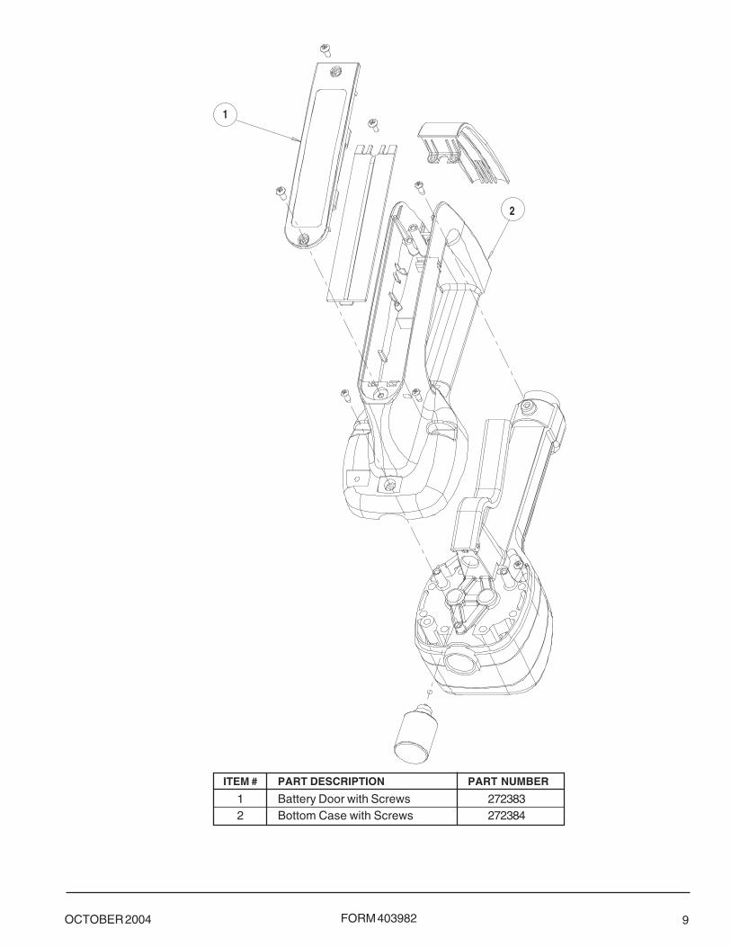
FORM 403982OCTOBER 2004 9
ITEM # PART DESCRIPTION PART NUMBER
1 Battery Door with Screws 2723832 Bottom Case with Screws 272384
2
1

FORM 403982 OCTOBER 200410
ITEM # PART DESCRIPTION PART NUMBER
1 Valve Assembly 2723732 Gear Service Kit with O-Ring 2723773 Trigger Assembly 272378
1
2
3

FORM 403982OCTOBER 2004 11
ITEM # PART DESCRIPTION PART NUMBER
1 Non-Drip Nozzle Assembly 847992 O-Ring and Washer Kit 2723903 Nozzle Assembly** 272391
** Consists of Items 1 and 2
©
©

FORM 403982 OCTOBER 200412
Troubleshooting
Relieve the pressure prior to checkingor repairing the meter. Make sure all
valves, controls and pumps areoperating correctly.
Symptom Fault Remedy
Battery Icon is displayed Batteries are low Replace batteries
Display Blank Meter asleep Push reset button
Batteries dead Replace batteries / Push resetbutton
Program error Remove and reinsert battery pack /Push reset button
Loose battery connection Remove battery pack and checkbattery connection / Push resetbutton
Meter does not latch for Meter not in AUTO mode Press AUTO button and programbatching batch size
Meter not reset after prior Press RESET buttonbatch
Low batteries Check for battery icon / replacebatteries / push RESET button
Slow or no fluid flow Filter is clogged Clean or replace the filter in theswivel nut
Pump pressure is low Turn up the pump pressure
Foreign material is Contact your local distributor forjamming meter repair
Meter inaccurate Scale factor not correct for Enter program mode check andfluid reset program factor
Batch overruns program Pulse delay value set too low Enter program mode, reset pulsevalue delay to higher value
AmericasOne Lincoln Way
St. Louis, MO 63120-1578USA
Phone +1 314 679 4200Fax +1 800 424 5359
Europe/AfricaHeinrich-Hertz-Str 2-8
D-69183 WalldorfGermany
Phone +49 6227 33 0Fax +49 6227 33 259
Asia/Pacific25 Int'l Business Park
#01-65 German CentreSingapore 609916
Phone +65 562 7960Fax +65 562 9967
Printed in USA
Websitewww.lincolnindustrial.com