electronic load · single-cell fuel cells. the continuing trend toward lower power consumption and...
TRANSCRIPT
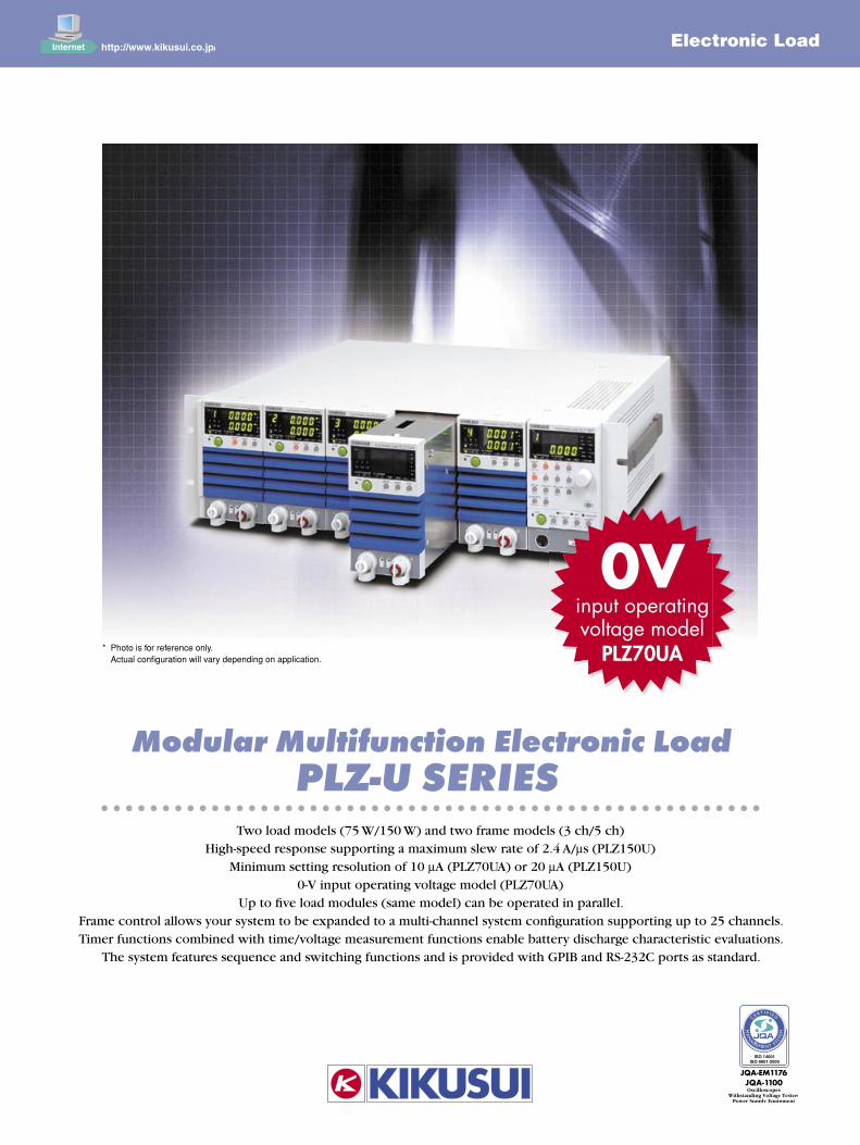
Modular Multifunction Electronic Load PLZ-U SERIES
Two load models (75 W/150 W) and two frame models (3 ch/5 ch)High-speed response supporting a maximum slew rate of 2.4 A/µs (PLZ150U)
Minimum setting resolution of 10 µA (PLZ70UA) or 20 µA (PLZ150U)0-V input operating voltage model (PLZ70UA)
Up to fi ve load modules (same model) can be operated in parallel.Frame control allows your system to be expanded to a multi-channel system confi guration supporting up to 25 channels.Timer functions combined with time/voltage measurement functions enable battery discharge characteristic evaluations.
The system features sequence and switching functions and is provided with GPIB and RS-232C ports as standard.
* Photo is for reference only. Actual confi guration will vary depending on application.
Electronic Load
0Vinput operatingvoltage model
PLZ70UA

2 3
The current trend in semiconductors is
towards lower voltages and higher speeds.
This trend places similar demands on
both the components of semiconductor
power units, such as switching power
supplies, batteries and DC/DC converters,
and also on the electronic loads used for
testing. Also, a growing number of users
with a need for multiple-output power units
and easy channel reconfi guration are
calling for plug-in type electronic loads
that can be easily confi gured to support
multiple channels. The advent of an
electronic load system that satisfi es all
these needs has been long awaited. It
was against this background that we
developed the PLZ-U Series of electronic
loads.
The PLZ-U Ser ies of compact and
high-performance modular electronic
loads is capable of operating in fi ve
modes: constant current, constant
resistance, constant voltage, constant
current + constant voltage, and constant
resistance + constant voltage. The load
system consists of load modules and a
frame. The load modules are inserted into
the frame that also serves as a control unit.
The PLZ-30F frame can accommodate up
to three load modules, while the PLZ-50F
frame can accommodate up to fi ve. The
load modules can be operated in parallel,
so that the current capacity or power
capacity can be changed easily, from 75
to 750 watts*1, as needed for the device
under test . In addi t ion to of fer ing
high-speed response at a maximum slew
rate of 2.4 A/µs*2 and a minimum setting
For Testing Switching Power Supplies, Batteries,DC/DC Converters and Fuel Cells!
resolution of 10 µA*3, the system features
a variety of functions including soft start,
variable slew rate, a switching function,
ABC preset memory function, four setup
memories, and a sequence function.
What’s more, timer functions combined
with time/voltage measurement functions
allow you to measure battery discharge
characteristics.
For communicat ion, the system is
prov ided wi th GPIB and RS-232C
interfaces as standard. Both interfaces
suppor t IEEE 488.2 as wel l as the
Standard Commands for Programmable
Instruments (SCPI) commands, developed
for testing and measuring instruments.
*1 When fi ve PLZ150U units are installed in a PLZ-50F frame
*2 For the PLZ150U
*3 For the PLZ70UA
Modular Multifunction Electronic Load NEW
PLZ-U SE RIESPLZ-U SE RIES
0Vinput operatingvoltage model
PLZ70UA
2 3
P L Z - U S E R I E SSERESUZLPP L Z - U S E R I E S
Compact, lightweight bodyThe electronic load system is as wide as
a 19-inch rack with a height of 3U.
Weighing about 11 kg when configured for
three channels or about 17 kg when
configured for five channels, the system is
compact, lightweight and space-saving.
High-speed responseIn constant current mode, the electronic
load is capable of offering high-speed
response at a slew rate of 2.4 A/µs at the
rising and falling edges of the current
(equivalent to about 10 µs when converted
to the rise and fall times; in the case of
PLZ150U). This allows transient response
tests for direct current power supplies and
simulations using dummy loads to be
conducted under highly realistic load
conditions.
High precision and high resolutionThe built-in three-range configuration
provides both wide dynamic range and
high precision. The voltmeter, ammeter
and wattmeter functions that display
values using up to five digits each and a
minimum setting resolution of either 10 µA
(PLZ70UA) or 20 µA (PLZ150U) are
implemented.
Variable slew rateIn constant current or constant resistance
mode, the slew rate can be changed
cont inuously. This helps suppress
transient voltage drops due to wiring
inductance, as well as transients in the
constant voltage power supply and others,
at the time of switching operation.
0-V inputThe PLZ70UA model operates even when
the input operating voltage is 0 V. This
feature is indispensable for test ing
single-cell fuel cells. The continuing trend
toward lower power consumption and
semiconductor process miniaturization is
driving semiconductor devices to operate
with increasingly lower voltages. This
makes PLZ70UA suitable for use when
evaluating such power supplies.
Multi-channel systemPLZ-50F may be configured with up to five
channels, and PLZ-30F may be configured
with up to three channels. Isolated from
each other, the channels can operate both
independently and in synchronization.
Different models of load units (PLZ150U
and PLZ70UA) can be housed in a single
frame.
Parallel operation for increased capacityUp to five load modules may be operated
in parallel, provided that adjacent load
modules are of the same model. For
example, when five load modules are
parallel connected in a PLZ-50F frame,
the system can function as a 375-watt
load if the paralleled load modules are
PLZ70UAs or as a 750-watt load if the
paralleled load modules are PLZ150Us.
Sequence function to enable load simulationsIn constant current or constant resistance
mode, sequence p rograms, each
consisting of up to 255 steps, can be
created with a minimum step execution
time of 1 ms. A separate program can be
run independently at the same time on a
channel-by-channel basis.
External control functionsYou can activate the input of an external
reference voltage and turn on or off the
load for each channel indiv idual ly.
Through the frame control terminals, you
can perform channel-synchronized ABC
preset memory call, setup memory call,
and load on/off operations.
Frame controlYou can connect two or more frames and
use one of them to control the others (up
to five frames can be connected at a
time). This enables you to turn on or off
the load and call preset values.
Others• A setup memory function is provided to save the panel settings.
• The ABC preset memory function lets you preset the three most frequently used values.
• The system comes standard with GPIB and RS-232C communication ports.
• The analog-like rotary knobs and intuitive design make the system very easy to operate.
• The system has load input terminals and remote sensing terminals on its front and rear panels.
• The use of heat-sensitive, variable-speed fans and the pursuit of a more efficient cooling
structure have resulted in high reliability and low noise.
• Six protection functions are provided, including over current protection (OCP), under
voltage protection (UVP) and reverse connection protection (RVP).
Features
4
P L Z - U S E R I E SSERESUZLPP L Z - U S E R I E S
5
P L Z - U S E R I E SSERESUZLPP L Z - U S E R I E S
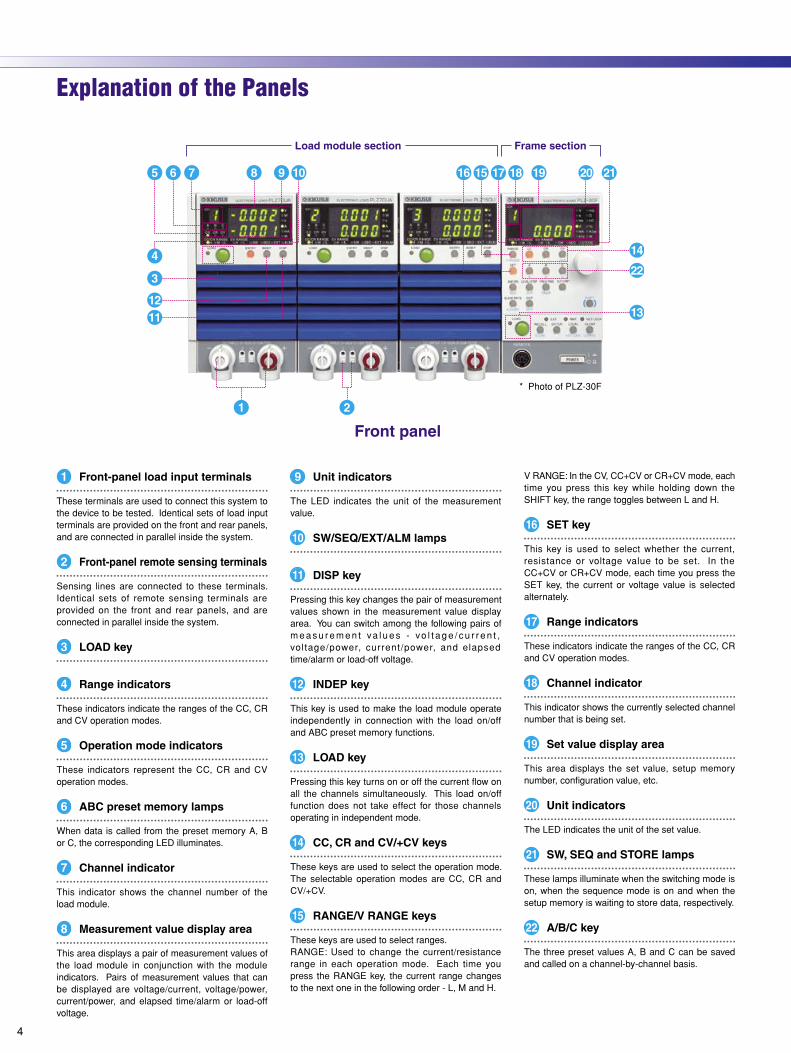
V RANGE: In the CV, CC+CV or CR+CV mode, each time you press this key while holding down the SHIFT key, the range toggles between L and H.
16 SET key
This key is used to select whether the current, resistance or voltage value to be set. In the CC+CV or CR+CV mode, each time you press the SET key, the current or voltage value is selected alternately.
17 Range indicators
These indicators indicate the ranges of the CC, CR and CV operation modes.
18 Channel indicator
This indicator shows the currently selected channel number that is being set.
19 Set value display area
This area displays the set value, setup memory number, configuration value, etc.
20 Unit indicators
The LED indicates the unit of the set value.
21 SW, SEQ and STORE lamps
These lamps illuminate when the switching mode is on, when the sequence mode is on and when the setup memory is waiting to store data, respectively.
22 A/B/C key
The three preset values A, B and C can be saved and called on a channel-by-channel basis.
9 Unit indicators
The LED indicates the unit of the measurement value.
10 SW/SEQ/EXT/ALM lamps
11 DISP key
Pressing this key changes the pair of measurement values shown in the measurement value display area. You can switch among the following pairs of m e a s u r e m e n t va l u e s - vo l t a g e / c u r r e n t , voltage/power, current/power, and elapsed time/alarm or load-off voltage.
12 INDEP key
This key is used to make the load module operate independently in connection with the load on/off and ABC preset memory functions.
13 LOAD key
Pressing this key turns on or off the current flow on all the channels simultaneously. This load on/off function does not take effect for those channels operating in independent mode.
14 CC, CR and CV/+CV keys
These keys are used to select the operation mode. The selectable operation modes are CC, CR and CV/+CV.
15 RANGE/V RANGE keys
These keys are used to select ranges.RANGE: Used to change the current/resistance range in each operation mode. Each time you press the RANGE key, the current range changes to the next one in the following order - L, M and H.
1 Front-panel load input terminals
These terminals are used to connect this system to the device to be tested. Identical sets of load input terminals are provided on the front and rear panels, and are connected in parallel inside the system.
2 Front-panel remote sensing terminals
Sensing lines are connected to these terminals. Identical sets of remote sensing terminals are provided on the front and rear panels, and are connected in parallel inside the system.
3 LOAD key
4 Range indicators
These indicators indicate the ranges of the CC, CR and CV operation modes.
5 Operation mode indicators
These indicators represent the CC, CR and CV operation modes.
6 ABC preset memory lamps
When data is called from the preset memory A, B or C, the corresponding LED illuminates.
7 Channel indicator
This indicator shows the channel number of the load module.
8 Measurement value display area
This area displays a pair of measurement values of the load module in conjunction with the module indicators. Pairs of measurement values that can be displayed are voltage/current, voltage/power, current/power, and elapsed time/alarm or load-off voltage.
Explanation of the Panels
* Photo of PLZ-30F
4
P L Z - U S E R I E SSERESUZLPP L Z - U S E R I E S
5
P L Z - U S E R I E SSERESUZLPP L Z - U S E R I E S
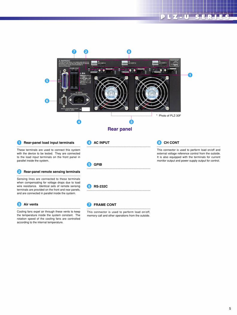
4 AC INPUT
5 GPIB
6 RS-232C
7 FRAME CONT
This connector is used to perform load on/off, memory call and other operations from the outside.
1 Rear-panel load input terminals
These terminals are used to connect this system with the device to be tested. They are connected to the load input terminals on the front panel in parallel inside the system.
2 Rear-panel remote sensing terminals
Sensing lines are connected to these terminals when compensating for voltage drops due to load wire resistance. Identical sets of remote sensing terminals are provided on the front and rear panels, and are connected in parallel inside the system.
3 Air vents
Cooling fans expel air through these vents to keep the temperature inside the system constant. The rotation speed of the cooling fans are controlled according to the internal temperature.
8 CH CONT
This connector is used to perform load on/off and external voltage reference control from the outside. It is also equipped with the terminals for current monitor output and power supply output for control.
* Photo of PLZ-30F
6
P L Z - U S E R I E SSERESUZLPP L Z - U S E R I E S
7
P L Z - U S E R I E SSERESUZLPP L Z - U S E R I E S
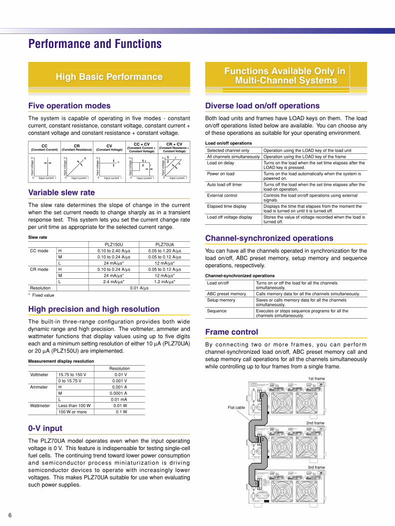
Five operation modesThe system is capable of operating in five modes - constant current, constant resistance, constant voltage, constant current + constant voltage and constant resistance + constant voltage.
Variable slew rateThe slew rate determines the slope of change in the current when the set current needs to change sharply as in a transient response test. This system lets you set the current change rate per unit time as appropriate for the selected current range.
Slew rate
PLZ150U PLZ70UACC mode H 0.10 to 2.40 A/µs 0.05 to 1.20 A/µs
M 0.10 to 0.24 A/µs 0.05 to 0.12 A/µsL 24 mA/µs* 12 mA/µs*
CR mode H 0.10 to 0.24 A/µs 0.05 to 0.12 A/µsM 24 mA/µs* 12 mA/µs*L 2.4 mA/µs* 1.2 mA/µs*
Resolution 0.01 A/µs
* Fixed value
High precision and high resolutionThe built-in three-range configuration provides both wide dynamic range and high precision. The voltmeter, ammeter and wattmeter functions that display values using up to five digits each and a minimum setting resolution of either 10 µA (PLZ70UA) or 20 µA (PLZ150U) are implemented.
Measurement display resolution
ResolutionVoltmeter 15.75 to 150 V 0.01 V
0 to 15.75 V 0.001 VAmmeter H 0.001 A
M 0.0001 AL 0.01 mA
Wattmeter Less than 100 W 0.01 W100 W or more 0.1 W
0-V inputThe PLZ70UA model operates even when the input operating voltage is 0 V. This feature is indispensable for testing single-cell fuel cells. The continuing trend toward lower power consumption and semiconductor process miniatur izat ion is dr iv ing semiconductor devices to operate with increasingly lower voltages. This makes PLZ70UA suitable for use when evaluating such power supplies.
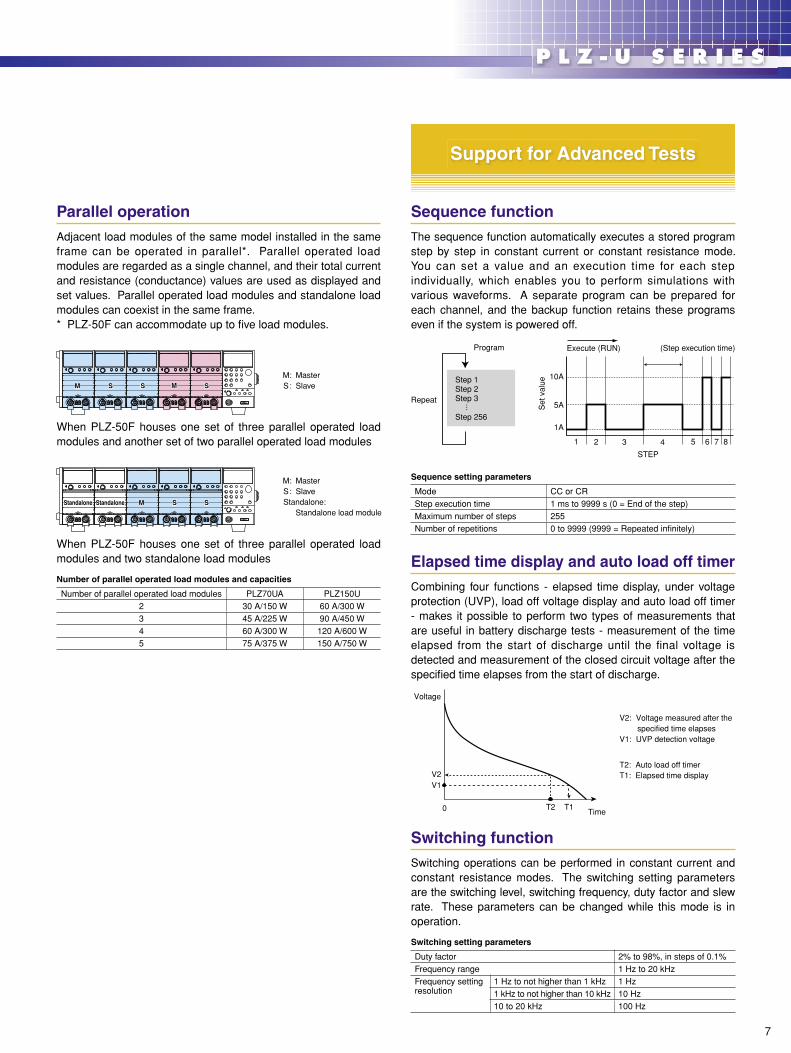
Diverse load on/off operationsBoth load units and frames have LOAD keys on them. The load on/off operations listed below are available. You can choose any of these operations as suitable for your operating environment.
Load on/off operations
Selected channel only Operation using the LOAD key of the load unitAll channels simultaneously Operation using the LOAD key of the frameLoad on delay Turns on the load when the set time elapses after the
LOAD key is pressed.Power on load Turns on the load automatically when the system is
powered on.Auto load off timer Turns off the load when the set time elapses after the
load-on operation.External control Controls the load on/off operations using external
signals.Elapsed time display Displays the time that elapses from the moment the
load is turned on until it is turned off.Load off voltage display Stores the value of voltage recorded when the load is
turned off.
Channel-synchronized operationsYou can have all the channels operated in synchronization for the load on/off, ABC preset memory, setup memory and sequence operations, respectively.
Channel-synchronized operations
Load on/off Turns on or off the load for all the channels simultaneously.
ABC preset memory Calls memory data for all the channels simultaneously.Setup memory Saves or calls memory data for all the channels
simultaneously.Sequence Executes or stops sequence programs for all the
channels simultaneously.
Frame controlBy connect ing two or more f rames, you can per form channel-synchronized load on/off, ABC preset memory call and setup memory call operations for all the channels simultaneously while controlling up to four frames from a single frame.
Performance and Functions
High Basic Performance
6
P L Z - U S E R I E SSERESUZLPP L Z - U S E R I E S
7
P L Z - U S E R I E SSERESUZLPP L Z - U S E R I E S
Parallel operationAdjacent load modules of the same model installed in the same frame can be operated in parallel*. Parallel operated load modules are regarded as a single channel, and their total current and resistance (conductance) values are used as displayed and set values. Parallel operated load modules and standalone load modules can coexist in the same frame.* PLZ-50F can accommodate up to five load modules.
When PLZ-50F houses one set of three parallel operated load modules and another set of two parallel operated load modules
When PLZ-50F houses one set of three parallel operated load modules and two standalone load modules
Number of parallel operated load modules and capacities
Number of parallel operated load modules PLZ70UA PLZ150U2 30 A/150 W 60 A/300 W3 45 A/225 W 90 A/450 W4 60 A/300 W 120 A/600 W5 75 A/375 W 150 A/750 W
Sequence functionThe sequence function automatically executes a stored program step by step in constant current or constant resistance mode. You can set a value and an execution time for each step individually, which enables you to perform simulations with various waveforms. A separate program can be prepared for each channel, and the backup function retains these programs even if the system is powered off.
Sequence setting parameters
Mode CC or CRStep execution time 1 ms to 9999 s (0 = End of the step)Maximum number of steps 255Number of repetitions 0 to 9999 (9999 = Repeated infinitely)
Elapsed time display and auto load off timerCombining four functions - elapsed time display, under voltage protection (UVP), load off voltage display and auto load off timer - makes it possible to perform two types of measurements that are useful in battery discharge tests - measurement of the time elapsed from the start of discharge until the final voltage is detected and measurement of the closed circuit voltage after the specified time elapses from the start of discharge.
Switching functionSwitching operations can be performed in constant current and constant resistance modes. The switching setting parameters are the switching level, switching frequency, duty factor and slew rate. These parameters can be changed while this mode is in operation.
Switching setting parameters
Duty factor 2% to 98%, in steps of 0.1%Frequency range 1 Hz to 20 kHzFrequency setting resolution
1 Hz to not higher than 1 kHz 1 Hz1 kHz to not higher than 10 kHz 10 Hz10 to 20 kHz 100 Hz
M: MasterS: Slave
M: MasterS: SlaveStandalone: Standalone load module
Support for Advanced Tests
8
P L Z - U S E R I E SSERESUZLPP L Z - U S E R I E S
9
P L Z - U S E R I E SSERESUZLPP L Z - U S E R I E S
Configuration settingThis function configures the settings related to the system operation, communication environment, etc. These settings are stored in the system memory and called when the power is turned on.
• Number of parallel operated load modules
• Operation mode in which the external reference voltage input is used
• Over current protection (OCP) load off function
• Over power protection (OPP) load off function
• Load on delay time
• Load on/off operation at the end of the sequence
• Polarity of load on external control (low/high)
• Load on/off operation at powering on
• Choice between GPIB and RS-232C
• GPIB address setting
• RS-232C communication speed
Ease of operationAll the knobs and keys necessary for the setting operations are provided on the frame panel. You can perform the setting operations by one hand while viewing the measured voltage and current values displayed on a channel-by-channel basis. The analog-like rotary knobs, which employ rotation speed-sensitive encoders, and intuitive design make the system very easy to operate.
Key lock functionThis function locks the panel keys so that the set values, memory data, sequences and other settings cannot be changed.
Numerous protection functionsThe system features the following protection functions - over current protection (OCP), over power protection (OPP), overvoltage protection (OVP), under voltage protection (UVP), over heat protection (OHP) and reverse connection protection (RVP). Because the OCP, OPP and UVP values can be changed on a per-channel basis, you can optimize the protection settings for each device to be tested.
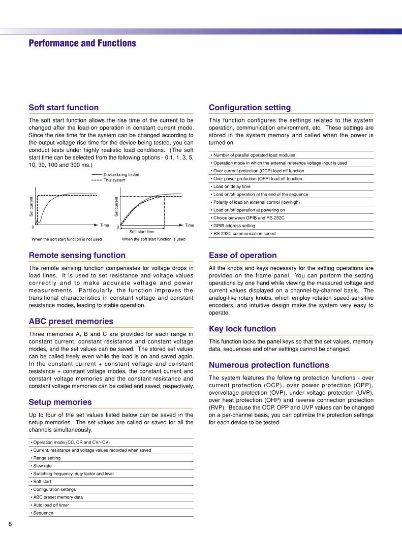
Soft start functionThe soft start function allows the rise time of the current to be changed after the load-on operation in constant current mode. Since the rise time for the system can be changed according to the output-voltage rise time for the device being tested, you can conduct tests under highly realistic load conditions. (The soft start time can be selected from the following options - 0.1, 1, 3, 5, 10, 30, 100 and 300 ms.)
Remote sensing functionThe remote sensing function compensates for voltage drops in load lines. It is used to set resistance and voltage values co r rec t l y and to make accura te vo l tage and power measurements. Par ticular ly, the function improves the transitional characteristics in constant voltage and constant resistance modes, leading to stable operation.
ABC preset memoriesThree memories A, B and C are provided for each range in constant current, constant resistance and constant voltage modes, and the set values can be saved. The stored set values can be called freely even while the load is on and saved again. In the constant current + constant voltage and constant resistance + constant voltage modes, the constant current and constant voltage memories and the constant resistance and constant voltage memories can be called and saved, respectively.
Setup memoriesUp to four of the set values listed below can be saved in the setup memories. The set values are called or saved for all the channels simultaneously.
• Operation mode (CC, CR and CV/+CV)
• Current, resistance and voltage values recorded when saved
• Range setting
• Slew rate
• Switching frequency, duty factor and level
• Soft start
• Configuration settings
• ABC preset memory data
• Auto load off timer
• Sequence
Performance and Functions
8
P L Z - U S E R I E SSERESUZLPP L Z - U S E R I E S
9
P L Z - U S E R I E SSERESUZLPP L Z - U S E R I E S
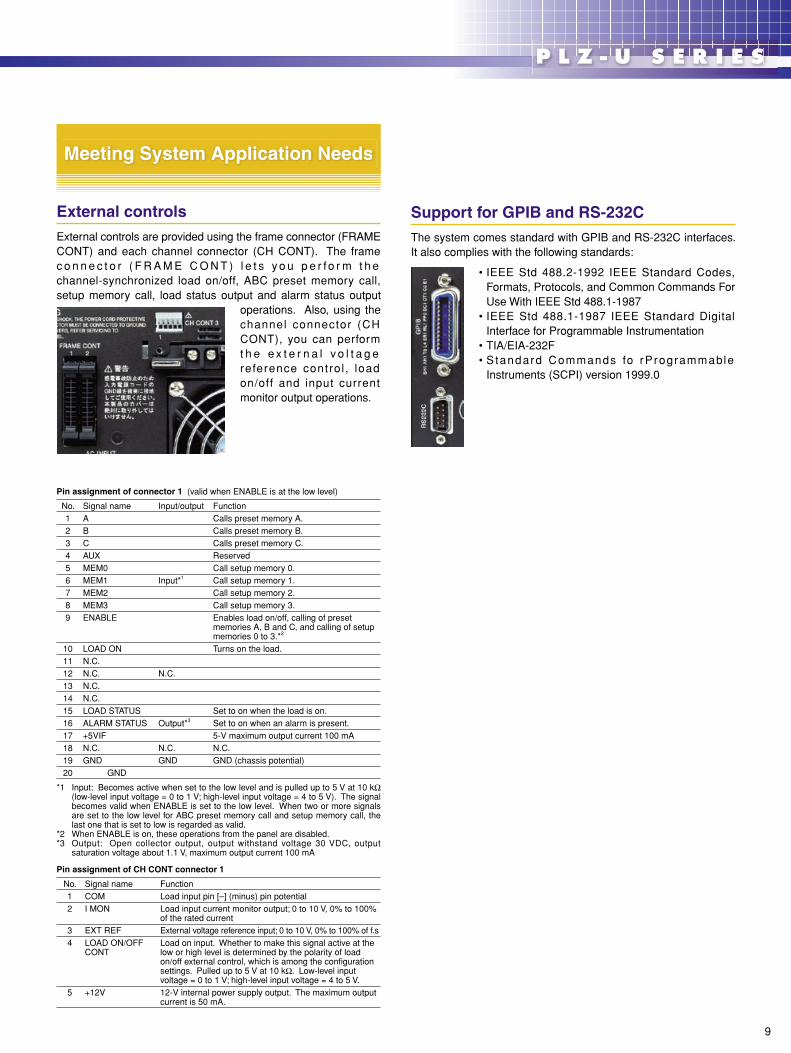
External controlsExternal controls are provided using the frame connector (FRAME CONT) and each channel connector (CH CONT). The frame c o n n e c t o r ( F R A M E C O N T ) l e t s y o u p e r f o r m t h e channel-synchronized load on/off, ABC preset memory call, setup memory call, load status output and alarm status output
operations. Also, using the channel connector (CH CONT), you can perform t h e e x t e r n a l v o l t a g e reference contro l , load on/off and input current monitor output operations.
Pin assignment of connector 1 (valid when ENABLE is at the low level)
No. Signal name Input/output Function1 A Calls preset memory A.2 B Calls preset memory B.3 C Calls preset memory C.4 AUX Reserved5 MEM0 Call setup memory 0.6 MEM1 Input*1 Call setup memory 1.7 MEM2 Call setup memory 2.8 MEM3 Call setup memory 3.9 ENABLE Enables load on/off, calling of preset
memories A, B and C, and calling of setup memories 0 to 3.*2
10 LOAD ON Turns on the load.11 N.C.12 N.C. N.C.13 N.C.14 N.C.15 LOAD STATUS Set to on when the load is on.16 ALARM STATUS Output*3 Set to on when an alarm is present.17 +5VIF 5-V maximum output current 100 mA18 N.C. N.C. N.C.19 GND GND GND (chassis potential)20 GND
*1 Input: Becomes active when set to the low level and is pulled up to 5 V at 10 kΩ (low-level input voltage = 0 to 1 V; high-level input voltage = 4 to 5 V). The signal becomes valid when ENABLE is set to the low level. When two or more signals are set to the low level for ABC preset memory call and setup memory call, the last one that is set to low is regarded as valid.
*2 When ENABLE is on, these operations from the panel are disabled.*3 Output: Open collector output, output withstand voltage 30 VDC, output
saturation voltage about 1.1 V, maximum output current 100 mA
Pin assignment of CH CONT connector 1
No. Signal name Function1 COM Load input pin [–] (minus) pin potential2 I MON Load input current monitor output; 0 to 10 V, 0% to 100%
of the rated current3 EXT REF External voltage reference input; 0 to 10 V, 0% to 100% of f.s4 LOAD ON/OFF
CONTLoad on input. Whether to make this signal active at the low or high level is determined by the polarity of load on/off external control, which is among the configuration settings. Pulled up to 5 V at 10 kΩ. Low-level input voltage = 0 to 1 V; high-level input voltage = 4 to 5 V.
5 +12V 12-V internal power supply output. The maximum output current is 50 mA.
Support for GPIB and RS-232CThe system comes standard with GPIB and RS-232C interfaces. It also complies with the following standards:
• IEEE Std 488.2-1992 IEEE Standard Codes, Formats, Protocols, and Common Commands For Use With IEEE Std 488.1-1987
• IEEE Std 488.1-1987 IEEE Standard Digital Interface for Programmable Instrumentation
• TIA/EIA-232F• S tandard Commands fo rProgrammable
Instruments (SCPI) version 1999.0
Meeting System Application Needs
10
P L Z - U S E R I E SSERESUZLPP L Z - U S E R I E S
11
P L Z - U S E R I E SSERESUZLPP L Z - U S E R I E SSpecificationsRating
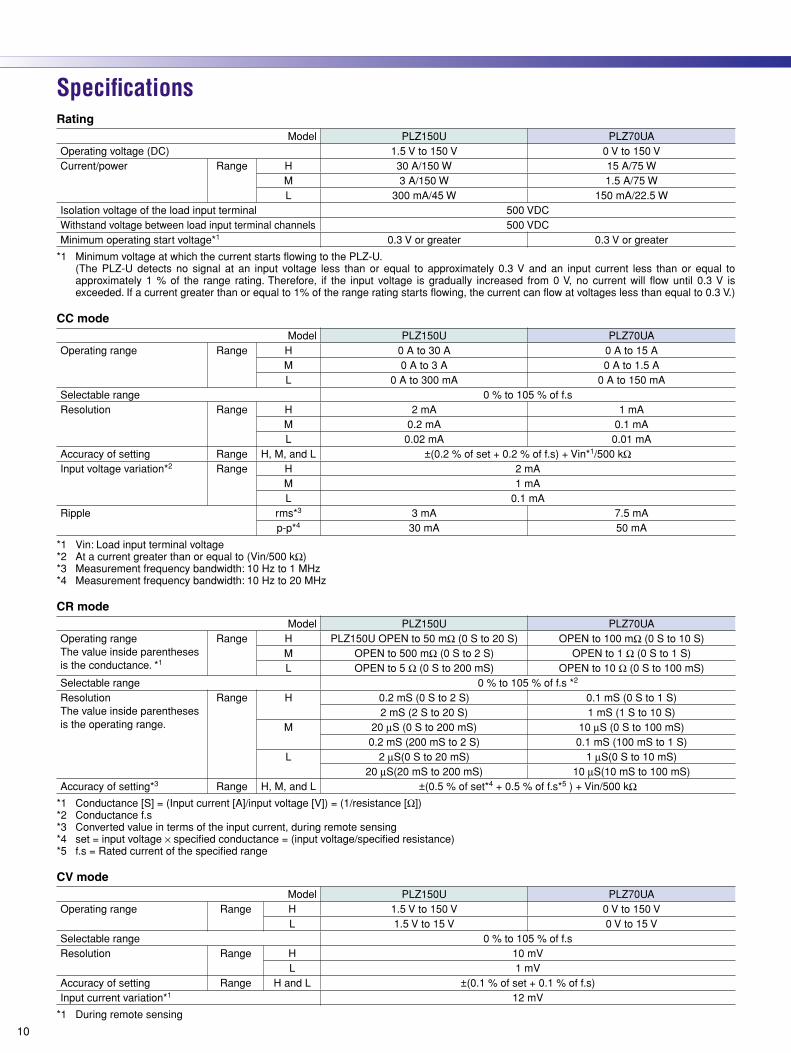
Model PLZ150U PLZ70UAOperating voltage (DC) 1.5 V to 150 V 0 V to 150 VCurrent/power Range H 30 A/150 W 15 A/75 W
M 3 A/150 W 1.5 A/75 WL 300 mA/45 W 150 mA/22.5 W
Isolation voltage of the load input terminal 500 VDCWithstand voltage between load input terminal channels 500 VDCMinimum operating start voltage*1 0.3 V or greater 0.3 V or greater
*1 Minimum voltage at which the current starts flowing to the PLZ-U. (The PLZ-U detects no signal at an input voltage less than or equal to approximately 0.3 V and an input current less than or equal to
approximately 1 % of the range rating. Therefore, if the input voltage is gradually increased from 0 V, no current will flow until 0.3 V is exceeded. If a current greater than or equal to 1% of the range rating starts flowing, the current can flow at voltages less than equal to 0.3 V.)
CC modeModel PLZ150U PLZ70UA
Operating range Range H 0 A to 30 A 0 A to 15 AM 0 A to 3 A 0 A to 1.5 AL 0 A to 300 mA 0 A to 150 mA
Selectable range 0 % to 105 % of f.sResolution Range H 2 mA 1 mA
M 0.2 mA 0.1 mAL 0.02 mA 0.01 mA
Accuracy of setting Range H, M, and L ±(0.2 % of set + 0.2 % of f.s) + Vin*1/500 kΩInput voltage variation*2 Range H 2 mA
M 1 mAL 0.1 mA
Ripple rms*3 3 mA 7.5 mAp-p*4 30 mA 50 mA
*1 Vin: Load input terminal voltage*2 At a current greater than or equal to (Vin/500 kΩ)*3 Measurement frequency bandwidth: 10 Hz to 1 MHz*4 Measurement frequency bandwidth: 10 Hz to 20 MHz
CR modeModel PLZ150U PLZ70UA
Operating rangeThe value inside parentheses is the conductance. *1
Range H PLZ150U OPEN to 50 mΩ (0 S to 20 S) OPEN to 100 mΩ (0 S to 10 S)M OPEN to 500 mΩ (0 S to 2 S) OPEN to 1 Ω (0 S to 1 S)L OPEN to 5 Ω (0 S to 200 mS) OPEN to 10 Ω (0 S to 100 mS)
Selectable range 0 % to 105 % of f.s *2
ResolutionThe value inside parentheses is the operating range.
Range H 0.2 mS (0 S to 2 S) 0.1 mS (0 S to 1 S)2 mS (2 S to 20 S) 1 mS (1 S to 10 S)
M 20 µS (0 S to 200 mS) 10 µS (0 S to 100 mS)0.2 mS (200 mS to 2 S) 0.1 mS (100 mS to 1 S)
L 2 µS(0 S to 20 mS) 1 µS(0 S to 10 mS)20 µS(20 mS to 200 mS) 10 µS(10 mS to 100 mS)
Accuracy of setting*3 Range H, M, and L ±(0.5 % of set*4 + 0.5 % of f.s*5 ) + Vin/500 kΩ*1 Conductance [S] = (Input current [A]/input voltage [V]) = (1/resistance [Ω])*2 Conductance f.s*3 Converted value in terms of the input current, during remote sensing*4 set = input voltage × specified conductance = (input voltage/specified resistance)*5 f.s = Rated current of the specified range
CV modeModel PLZ150U PLZ70UA
Operating range Range H 1.5 V to 150 V 0 V to 150 VL 1.5 V to 15 V 0 V to 15 V
Selectable range 0 % to 105 % of f.sResolution Range H 10 mV
L 1 mVAccuracy of setting Range H and L ±(0.1 % of set + 0.1 % of f.s)Input current variation*1 12 mV
*1 During remote sensing
10
P L Z - U S E R I E SSERESUZLPP L Z - U S E R I E S
11
P L Z - U S E R I E SSERESUZLPP L Z - U S E R I E S
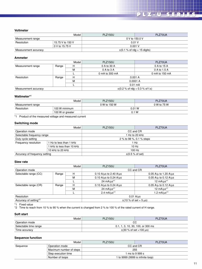
VoltmeterModel PLZ150U PLZ70UA
Measurement range 0 V to 150.0 VResolution 15.75 V to 150 V 0.01 V
0 V to 15.75 V 0.001 VMeasurement accuracy ±(0.1 % of rdg + 15 digits)
AmmeterModel PLZ150U PLZ70UA
Measurement range Range H 0 A to 30 A 0 A to 15 AM 0 A to 3 A 0 A to 1.5 AL 0 mA to 300 mA 0 mA to 150 mA
Resolution Range H 0.001 AM 0.0001 AL 0.01 mA
Measurement accuracy ±(0.2 % of rdg + 0.3 % of f.s)
Wattmeter*1
Model PLZ150U PLZ70UAMeasurement range 0 W to 150 W 0 W to 75 WResolution 100 W minimum 0.01 W
100 W or greater 0.1 W
*1 Product of the measured voltage and measured current
Switching modeModel PLZ150U PLZ70UA
Operation mode CC and CRSelectable frequency range 1 Hz to 20 kHzDuty cycle setting 2 % to 98 %, 0.1 % stepsFrequency resolution 1 Hz to less than 1 kHz 1 Hz
1 kHz to less than 10 kHz 10 Hz10 kHz to 20 kHz 100 Hz
Accuracy of frequency setting ±(0.5 % of set)
Slew rateModel PLZ150U PLZ70UA
Operation mode CC and CRSelectable range (CC) Range H 0.10 A/µs to 2.40 A/µs 0.05 A/µ to 1.20 A/µs
M 0.10 A/µs to 0.24 A/µs 0.05 A/µ to 0.12 A/µsL 24 mA/µs*1 12 mA/µs*1
Selectable range (CR) Range H 0.10 A/µs to 0.24 A/µs 0.05 A/µ to 0.12 A/µsM 24 mA/µs*1 12 mA/µs*1
L 2.4 mA/µs*1 1.2 mA/µs*1
Resolution 0.01 A/µsAccuracy of setting*2 ±(10 % of set + 5 µs)
*1 Fixed value*2 Time to reach from 10 % to 90 % when the current is changed from 2 % to 100 % of the rated current of H range.
Soft startModel PLZ150U PLZ70UA
Operation mode CCSelectable time range 0.1, 1, 3, 10, 30, 100, or 300 msTime accuracy ±(30 % of set +100 µs)
Sequence functionModel PLZ150U PLZ70UA
Sequence Operation mode CC and CRMaximum number of steps 255Step execution time 1 ms to 9 999 sNumber of loops 1 to 9999 (9999 is infinite loop)
12
P L Z - U S E R I E SSERESUZLPP L Z - U S E R I E S
13
P L Z - U S E R I E SSERESUZLPP L Z - U S E R I E SSpecifications
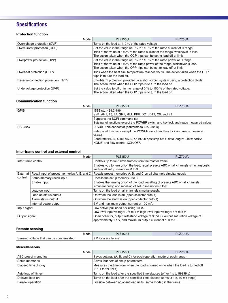
Protection functionModel PLZ150U PLZ70UA
Overvoltage protection (OVP) Turns off the load at 110 % of the rated voltageOvercurrent protection (OCP) Set the value in the range of 0 % to 110 % of the rated current of H range.
Trips at the value or 110% of the rated current of the range, whichever is less.The action taken when the OCP trips can be set to load off or limit.
Overpower protection (OPP) Set the value in the range of 0 % to 110 % of the rated power of H range. Trips at the value or 110% of the rated power of the range, whichever is less.The action taken when the OPP trips can be set to load off or limit.
Overheat protection (OHP) Trips when the heat sink temperature reaches 95 °C. The action taken when the OHP trips is to turn the load off.
Reverse connection protection (RVP) Short-term protection provided by a short-circuit system using a protection diode. The action taken when the OHP trips is to turn the load off.
Undervoltage protection (UVP) Set the value to off or in the range of 0 % to 100 % of the rated voltage.The action taken when the OHP trips is to turn the load off.
Communication functionModel PLZ150U PLZ70UA
GPIB IEEE std. 488.2-1994SH1, AH1, T6, L4, SR1, RL1, PP0, DC1, DT1, C0, and E1Supports the SCPI command setSets panel functions except the POWER switch and key lock and reads measured values
RS-232C D-SUB 9-pin connector (conforms to EIA-232-D)Sets panel functions except the POWER switch and key lock and reads measured valuesBaud rate: 2400, 4800, 9600, or 19200 bps; stop bit: 1; data length: 8 bits; parity: NONE; and flow control: XON/OFF.
Inter-frame control and external controlModel PLZ150U PLZ70UA
Inter-frame control Controls up to four slave frames from the master frame.Enables you to turn on/off the load, recall presets ABC on all channels simultaneously, and recall setup memories 0 to 3.
External control
Recall input of preset mem-ories A, B, and C Recalls preset memories A, B, and C on all channels simultaneouslySetup memory recall input Recalls the setup memory 0 to 3Enable input Enables the turning on/off of the load, recalling of presets ABC on all channels
simultaneously, and recalling of setup memories 0 to 3.Load-on input Turns on the load on all channels simultaneously.Load on status output On when the load is on (open collector output)Alarm status output On when the alarm is on (open collector output)Internal power output 5 V and maximum output current of 100 mA
Input signal Low active, pull up to 5 V using 10 kΩ.Low level input voltage: 0 V to 1 V, high level input voltage: 4 V to 5 V
Output signal Open collector, output withstand voltage of 30 VDC, output saturation voltage of approximately 1.1 V, and maximum output current of 100 mA.
Remote sensingModel PLZ150U PLZ70UA
Sensing voltage that can be compensated 2 V for a single line
MiscellaneousModel PLZ150U PLZ70UA
ABC preset memories Saves settings (A, B, and C) for each operation mode of each rangeSetup memories Saves four sets of setup parametersElapsed time display Measures the time from when the load is turned on to when the load is turned off
(0.1 s to 99999 s)Auto load off timer Turns off the load after the specified time elapses (off or 1 s to 99999 s)Delayed load-on Turns on the load after the specified time elapses (0 ms to 1 s, 10 ms steps)Parallel operation Possible between adjacent load units (same model) in the frame.
12
P L Z - U S E R I E SSERESUZLPP L Z - U S E R I E S
13
P L Z - U S E R I E SSERESUZLPP L Z - U S E R I E S
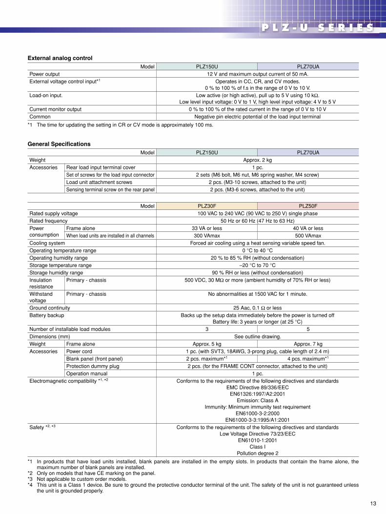
External analog controlModel PLZ150U PLZ70UA
Power output 12 V and maximum output current of 50 mA.External voltage control input*1 Operates in CC, CR, and CV modes.
0 % to 100 % of f.s in the range of 0 V to 10 V.Load-on input. Low active (or high active), pull up to 5 V using 10 kΩ.
Low level input voltage: 0 V to 1 V, high level input voltage: 4 V to 5 VCurrent monitor output 0 % to 100 % of the rated current in the range of 0 V to 10 VCommon Negative pin electric potential of the load input terminal
*1 The time for updating the setting in CR or CV mode is approximately 100 ms.
General SpecificationsModel PLZ150U PLZ70UA
Weight Approx. 2 kgAccessories Rear load input terminal cover 1 pc.
Set of screws for the load input connector 2 sets (M6 bolt, M6 nut, M6 spring washer, M4 screw)Load unit attachment screws 2 pcs. (M3-10 screws, attached to the unit)Sensing terminal screw on the rear panel 2 pcs. (M3-6 screws, attached to the unit)
Model PLZ30F PLZ50FRated supply voltage 100 VAC to 240 VAC (90 VAC to 250 V) single phaseRated frequency 50 Hz or 60 Hz (47 Hz to 63 Hz)Power consumption
Frame alone 33 VA or less 40 VA or lessWhen load units are installed in all channels 300 VAmax 500 VAmax
Cooling system Forced air cooling using a heat sensing variable speed fan.Operating temperature range 0 °C to 40 °COperating humidity range 20 % to 85 % RH (without condensation)Storage temperature range –20 °C to 70 °CStorage humidity range 90 % RH or less (without condensation)Insulation resistance
Primary - chassis 500 VDC, 30 MΩ or more (ambient humidity of 70% RH or less)
Withstand voltage
Primary - chassis No abnormalities at 1500 VAC for 1 minute.
Ground continuity 25 Aac, 0.1 Ω or lessBattery backup Backs up the setup data immediately before the power is turned off
Battery life: 3 years or longer (at 25 °C)Number of installable load modules 3 5Dimensions (mm) See outline drawing.Weight Frame alone Approx. 5 kg Approx. 7 kgAccessories Power cord 1 pc. (with SVT3, 18AWG, 3-prong plug, cable length of 2.4 m)
Blank panel (front panel) 2 pcs. maximum*1 4 pcs. maximum*1
Protection dummy plug 2 pcs. (for the FRAME CONT connector, attached to the unit)Operation manual 1 pc.
Electromagnetic compatibility *1, *2 Conforms to the requirements of the following directives and standardsEMC Directive 89/336/EEC
EN61326:1997/A2:2001Emission: Class A
Immunity: Minimum immunity test requirementEN61000-3-2:2000
EN61000-3-3:1995/A1:2001Safety *2, *3 Conforms to the requirements of the following directives and standards
Low Voltage Directive 73/23/EECEN61010-1:2001
Class IPollution degree 2
*1 In products that have load units installed, blank panels are installed in the empty slots. In products that contain the frame alone, the maximum number of blank panels are installed.
*2 Only on models that have CE marking on the panel.*3 Not applicable to custom order models.*4 This unit is a Class 1 device. Be sure to ground the protective conductor terminal of the unit. The safety of the unit is not guaranteed unless
the unit is grounded properly.
14
P L Z - U S E R I E SSERESUZLPP L Z - U S E R I E S
15
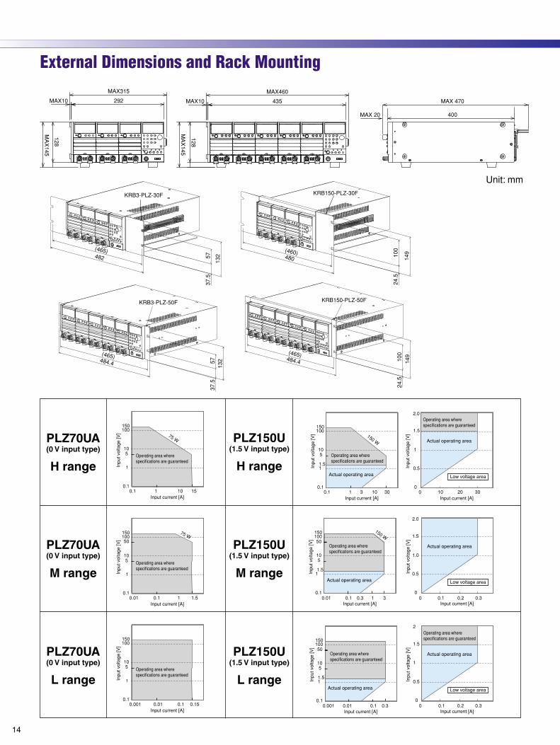
P L Z - U S E R I E SSERESUZLPP L Z - U S E R I E SExternal Dimensions and Rack Mounting
14
P L Z - U S E R I E SSERESUZLPP L Z - U S E R I E S
15
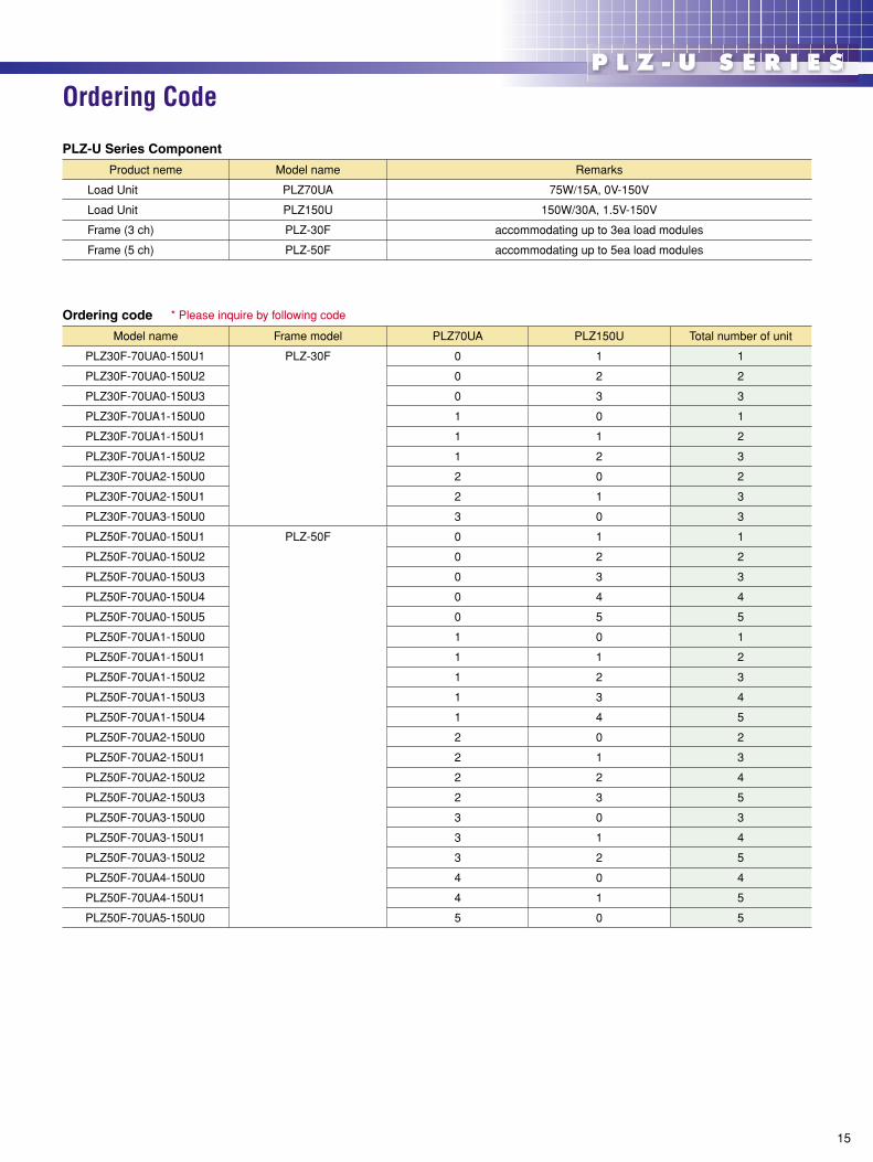
P L Z - U S E R I E SSERESUZLPP L Z - U S E R I E SOrdering Code
PLZ-U Series Component
Product neme Model name Remarks
Load Unit PLZ70UA 75W/15A, 0V-150V
Load Unit PLZ150U 150W/30A, 1.5V-150V
Frame (3 ch) PLZ-30F accommodating up to 3ea load modules
Frame (5 ch) PLZ-50F accommodating up to 5ea load modules
Ordering code * Please inquire by following code
Model name Frame model PLZ70UA PLZ150U Total number of unit
PLZ30F-70UA0-150U1 PLZ-30F 0 1 1
PLZ30F-70UA0-150U2 0 2 2
PLZ30F-70UA0-150U3 0 3 3
PLZ30F-70UA1-150U0 1 0 1
PLZ30F-70UA1-150U1 1 1 2
PLZ30F-70UA1-150U2 1 2 3
PLZ30F-70UA2-150U0 2 0 2
PLZ30F-70UA2-150U1 2 1 3
PLZ30F-70UA3-150U0 3 0 3
PLZ50F-70UA0-150U1 PLZ-50F 0 1 1
PLZ50F-70UA0-150U2 0 2 2
PLZ50F-70UA0-150U3 0 3 3
PLZ50F-70UA0-150U4 0 4 4
PLZ50F-70UA0-150U5 0 5 5
PLZ50F-70UA1-150U0 1 0 1
PLZ50F-70UA1-150U1 1 1 2
PLZ50F-70UA1-150U2 1 2 3
PLZ50F-70UA1-150U3 1 3 4
PLZ50F-70UA1-150U4 1 4 5
PLZ50F-70UA2-150U0 2 0 2
PLZ50F-70UA2-150U1 2 1 3
PLZ50F-70UA2-150U2 2 2 4
PLZ50F-70UA2-150U3 2 3 5
PLZ50F-70UA3-150U0 3 0 3
PLZ50F-70UA3-150U1 3 1 4
PLZ50F-70UA3-150U2 3 2 5
PLZ50F-70UA4-150U0 4 0 4
PLZ50F-70UA4-150U1 4 1 5
PLZ50F-70UA5-150U0 5 0 5

Printed in Japan Issue:June.2004 2004063KJEC11
All products contained in this catalogue are equipment and devices that are premised on use under the supervision of qualified personnel, and are not designed or produced for home-use or use by general consumers. Specifications, design and so forth are subject to change without prior notice to improve the quality. Product names and prices are subject to change and production may be discontinued when necessary. Product names, company names and brand names contained in this catalogue represent the respective registered trade name or trade mark. Colors, textures and so forth of photographs shown in this catalogue may differ from actual products due to a limited fidelity in printing. Although every effort has been made to provide the information as accurate as possible for this catalogue, certain details have unavoidably been omitted due to limitations in space. If you find any misprints or errors in this catalogue, it would be appreciated if you would inform us. Please contact our distributors to confirm specifications, price, accessories or anything that may be unclear when placing an order or concluding a purchasing agreement.
Distributor:
1-1-3,HIGASHIYAMATA,TSUZUKI-KU,YOKOHAMA, 224-0023, JAPANTEL:(045)593-7570, Fax:(045)593-7571
Internet:http://www.kikusui.co.jp/
KIKUSUI ELECTRONICS CORP.
Recycled Paper