electronic engine remote control - vetus® electronic engine remote control 030624.02 3 1....
TRANSCRIPT

Electronic engine
remote control
Operation manual
and
installation instructions
Copyright © 2008 Vetus n.v. Schiedam Hol land
ENGLISH
Electronic engine

2 030624.02 vetus®Electronic engine remote control
Contents1. Introduction . . . . . . . . . . . . . . . . . . . . . . . . . . . . . . . . . . . . . . . . . . . . . . . . . . . . . . . . . . . . . . . . . . . 32. General characteristics of the installation . . . . . . . . . . . . . . . . . . . . . . . . . . . . . . . . . . . . . . . . . . . . 3
2.1. Description of the system and its parts . . . . . . . . . . . . . . . . . . . . . . . . . . . . . . . . . . . . . . . . . 32.2. Maximum extension of the system . . . . . . . . . . . . . . . . . . . . . . . . . . . . . . . . . . . . . . . . . . . . . 32.3 Performance of the system . . . . . . . . . . . . . . . . . . . . . . . . . . . . . . . . . . . . . . . . . . . . . . . . . . . 3
3. Operating lever– Instructions for the user . . . . . . . . . . . . . . . . . . . . . . . . . . . . . . . . . . . . . . . . . . . 43.1. Adjusting the clutch . . . . . . . . . . . . . . . . . . . . . . . . . . . . . . . . . . . . . . . . . . . . . . . . . . . . . . . . . 43.2. The keyboard for the controls . . . . . . . . . . . . . . . . . . . . . . . . . . . . . . . . . . . . . . . . . . . . . . . . 43.3. Taking over control . . . . . . . . . . . . . . . . . . . . . . . . . . . . . . . . . . . . . . . . . . . . . . . . . . . . . . . . . 53.4. Warming up the engine (Warm-up) . . . . . . . . . . . . . . . . . . . . . . . . . . . . . . . . . . . . . . . . . . . . 53.5. Functioning in synchronous mode (Synchro) . . . . . . . . . . . . . . . . . . . . . . . . . . . . . . . . . . . . 63.6. Behaviour of the installation when malfunctioning . . . . . . . . . . . . . . . . . . . . . . . . . . . . . . . . 63.7. Identification labels . . . . . . . . . . . . . . . . . . . . . . . . . . . . . . . . . . . . . . . . . . . . . . . . . . . . . . . . . 6
4. Control box . . . . . . . . . . . . . . . . . . . . . . . . . . . . . . . . . . . . . . . . . . . . . . . . . . . . . . . . . . . . . . . . . . . 64.1. Type of installations . . . . . . . . . . . . . . . . . . . . . . . . . . . . . . . . . . . . . . . . . . . . . . . . . . . . . . . . 64.2. Emergency levers . . . . . . . . . . . . . . . . . . . . . . . . . . . . . . . . . . . . . . . . . . . . . . . . . . . . . . . . . . . 8
5. Guidance in the choice of the electronic system . . . . . . . . . . . . . . . . . . . . . . . . . . . . . . . . . . . . . . 85.1. Operating stations . . . . . . . . . . . . . . . . . . . . . . . . . . . . . . . . . . . . . . . . . . . . . . . . . . . . . . . . . . 85.2. Control boxes . . . . . . . . . . . . . . . . . . . . . . . . . . . . . . . . . . . . . . . . . . . . . . . . . . . . . . . . . . . . . . 8
6. Mechanical installation . . . . . . . . . . . . . . . . . . . . . . . . . . . . . . . . . . . . . . . . . . . . . . . . . . . . . . . . . . 96.1. Dimensions of the operating station . . . . . . . . . . . . . . . . . . . . . . . . . . . . . . . . . . . . . . . . . . . . 96.2. Dimensions of the control box . . . . . . . . . . . . . . . . . . . . . . . . . . . . . . . . . . . . . . . . . . . . . . . . . 96.3. Positioning the control box . . . . . . . . . . . . . . . . . . . . . . . . . . . . . . . . . . . . . . . . . . . . . . . . . . . 9
7. Coupling of the push-pull cable . . . . . . . . . . . . . . . . . . . . . . . . . . . . . . . . . . . . . . . . . . . . . . . . . . 107.1. Preliminary instruction . . . . . . . . . . . . . . . . . . . . . . . . . . . . . . . . . . . . . . . . . . . . . . . . . . . . . . 107.2. Fixing kit . . . . . . . . . . . . . . . . . . . . . . . . . . . . . . . . . . . . . . . . . . . . . . . . . . . . . . . . . . . . . . . . 10
7.2.1. Standard push-pull cables. . . . . . . . . . . . . . . . . . . . . . . . . . . . . . . . . . . . . . . . . . . . . 107.2.2. Outgoing push-pull cable with Mercruiser outdrive® . . . . . . . . . . . . . . . . . . . . . . . . 117.2.3. Push-pull cable type Johnson® . . . . . . . . . . . . . . . . . . . . . . . . . . . . . . . . . . . . . . . . 11
8. Electrical installation . . . . . . . . . . . . . . . . . . . . . . . . . . . . . . . . . . . . . . . . . . . . . . . . . . . . . . . . . . . 128.1. Installation of power supply . . . . . . . . . . . . . . . . . . . . . . . . . . . . . . . . . . . . . . . . . . . . . . . . . 128.2. Power supply . . . . . . . . . . . . . . . . . . . . . . . . . . . . . . . . . . . . . . . . . . . . . . . . . . . . . . . . . . . . . 12
8.2.1. Connector for the power supply . . . . . . . . . . . . . . . . . . . . . . . . . . . . . . . . . . . . . . . . 128.3. Outgoing cables from the control box . . . . . . . . . . . . . . . . . . . . . . . . . . . . . . . . . . . . . . . . . . . . . . 13
8.3.1. Card in control box . . . . . . . . . . . . . . . . . . . . . . . . . . . . . . . . . . . . . . . . . . . . . . . . . . 138.3.2. Relay card . . . . . . . . . . . . . . . . . . . . . . . . . . . . . . . . . . . . . . . . . . . . . . . . . . . . . . . . . 14
9. Programming . . . . . . . . . . . . . . . . . . . . . . . . . . . . . . . . . . . . . . . . . . . . . . . . . . . . . . . . . . . . . . . . . 159.1. Keyboard for programming . . . . . . . . . . . . . . . . . . . . . . . . . . . . . . . . . . . . . . . . . . . . . . . . . 15
10. Installations with electronically operated engine and mechanically operated gearbox. . . . . . . . 1610.1. Fitting the push-pull cable . . . . . . . . . . . . . . . . . . . . . . . . . . . . . . . . . . . . . . . . . . . . . . . . . . 1610.2. Setting the parameters . . . . . . . . . . . . . . . . . . . . . . . . . . . . . . . . . . . . . . . . . . . . . . . . . . . . . 16
10.2.1. Mechanical setting of the stroke of the gearbox . . . . . . . . . . . . . . . . . . . . . . . . . . . 1710.2.2. Specific parameters . . . . . . . . . . . . . . . . . . . . . . . . . . . . . . . . . . . . . . . . . . . . . . . . . 17
10.3 Setting values for the outgoing voltages . . . . . . . . . . . . . . . . . . . . . . . . . . . . . . . . . . . . . . . 1811. Control box for installations with electronically operated engine and electrically oper-
ated gearbox . . . . . . . . . . . . . . . . . . . . . . . . . . . . . . . . . . . . . . . . . . . . . . . . . . . . . . . . . . . . . . . . . 1911.1. Operating electrically operated gearbox . . . . . . . . . . . . . . . . . . . . . . . . . . . . . . . . . . . . . . . 1911.2. Setting values for the outgoing voltages . . . . . . . . . . . . . . . . . . . . . . . . . . . . . . . . . . . . . . . 1911.3. Cabling of the outgoing cables from the control box . . . . . . . . . . . . . . . . . . . . . . . . . . . . . 19
12. Option . . . . . . . . . . . . . . . . . . . . . . . . . . . . . . . . . . . . . . . . . . . . . . . . . . . . . . . . . . . . . . . . . . . . . . . 2012.1. Operating trim . . . . . . . . . . . . . . . . . . . . . . . . . . . . . . . . . . . . . . . . . . . . . . . . . . . . . . . . . . . . 2012.2. Electrical cables and plugs . . . . . . . . . . . . . . . . . . . . . . . . . . . . . . . . . . . . . . . . . . . . . . . . . . 20
12.2.1. Cables for electronically operated engine . . . . . . . . . . . . . . . . . . . . . . . . . . . . . . . . 2012.2.2. Trim cables / electrically operated gearbox . . . . . . . . . . . . . . . . . . . . . . . . . . . . . . . 2012.2.4. T-plug for an extra operating station . . . . . . . . . . . . . . . . . . . . . . . . . . . . . . . . . . . . . 21
13. Behaviour of installation in the event of irregularities . . . . . . . . . . . . . . . . . . . . . . . . . . . . . . . . . . 2113.1. Unforeseen switching off of the engines . . . . . . . . . . . . . . . . . . . . . . . . . . . . . . . . . . . . . . . 2113.2. Faults in the electrical network . . . . . . . . . . . . . . . . . . . . . . . . . . . . . . . . . . . . . . . . . . . . . . . 21
14. Drill pattern . . . . . . . . . . . . . . . . . . . . . . . . . . . . . . . . . . . . . . . . . . . . . . . . . . . . . . . . . . . . . . . . . . . 22

030624.02 3vetus® Electronic engine remote control
1. Introduction
This manual describes the electronic engine remote control in general and deals particularly with operating, the performance and the safety aspects. This is also an installation manual for installers.
2. General characteristics of the installation
2.1. Description of the system and its parts The electronic engine remote control couples mechanical-electronic solutions to digital communication technol-ogy so that flexible, reliable and easy to install modular systems can be achieved. Only a few pieces of equip-ment are required to compose a complete electronic engine remote control.
The electronic engine remote control consists in principle of three components that differ in number and type depending on the installation requirements: • operatinglevers• controlboxes• datatransfercablesthatconnecttheoperatingcontrolstothecontrolboxes
2.2. Maximum extension of the system The maximum configuration of the system is as shown in the table.
Control boxes The maximum number of engines that the system can control is 2
Operating levers The maximum number of operating levers in the installation is 3
2.3 Performance of the system
Temperature
Operating temperature From -10 to 85 °C
Storage temperature From -40 to 90 °C
Mechanical characteristics
Nominal load when control box is providing a pushing force
150 N (15 kg) with power consumption 1.5 A
Maximum load when control box is providing a pushing force
450 N (45 kg) with power consumption 5 A (with time <1 s)
Stroke of gearbox - forwardThe stroke can be set to between 5 and 40 mm
Stroke of gearbox – reverse
Max. movement of throttle (if mechanical) The movement can be set to between 5 and 80 mm
Electrical characteristics
Power supply From 9.0 to 16 V
Max. current taken 5 A
Current taken when not loaded 0.5 A

4 030624.02 vetus®Electronic engine remote control
3. Operating lever– Instructions for the user
The operating lever works as shown in the figure. Each operating lever is suitable for controlling 1 or 2 engines. One operating lever replicates the functions of a mechanical single lever control.
Starting from neutral, the engine is set to forward or reverse after making a movement of 16° either forwards or back-wards.
Should the fixing bolts not be long enough extension pieces can be supplied. We strongly recommend not to replace the fixing bolts present so as not to disrupt the operating station.
3.1. Adjusting the clutchIn order to adjust the clutch of the operating lever all that is required is to remove the PVC cap (A), unscrew the bolt fixing the lever (B) and remove the lever. The adjusting bolt then only has to be tightened/loosened in hole C in order to make the clutch of the lever tighter or less tight. After making the adjustment refit the lever and the cap. N.B.: if the control unit is only for a single engine there is only a clutch in the operating lever on the right.
3.2. The keyboard for the controls There is a keyboard panel on the operating control with 4 buttons and 4 LEDs.
Name Colour of LED
Engine (*) Green
Warm/Sync Orange
Command Red
Engine (*) Green
(*) For systems with only one engine both LEDS for the keys Engine refer to the same engine. For systems with two engines the key Engine and the corresponding LED on the keyboard refer to the same physical position of the engine, that is the button and the LED on the right refer to the right (starboard) engine and the button and the LED on the left refer to the left (port) engine.
Max. Max.M
in.M
in.
16°16°
67°67°
NeutralIdle forwardIdle reverse
Full speedFull
spee
d
A
B
C
vetus

030624.02 5vetus® Electronic engine remote control
The meaning of the LEDs and the buttons is shown in the table.
Button LED Meaning
(Operating) (Reporting)
Engine - If the LED is on the corresponding engine is in neutral
Command - If the LED is off the station does not have control over the installation
- If the LED is on the station has control over the installation
Warm/Sync- If the LED flashes it is busy with the WARM-UP, i.e. the engine/engines
can run at increased speed because the gearbox is still in neutral.
- If the LED is on the installation is functioning in synchronous mode. Both engines are controlled by the right-hand lever and the right-hand trim appliance controls both trims (if present)
Warm/Sync- After setting both levers of the operating station in neutral hold the
warm/sync key pressed in for at least three seconds; the WARM-UP function will now operate
Command- Control of the installation is gained by holding the Command key
pressed in for at least three seconds, provided that the operating lever is in neutral
All LEDs flash - The installation is malfunctioning
3.3. Taking over control Control of the installation can be taken over at any operating station by carrying out one of the following actions.
• Whenvesselisnotmoving
1. Position all operating levers in neutral. 2. Hold the Command key pressed in for at least three seconds. 3. The LED Command will come on and the LED Warm/Sync begin to flash. 4. The installation is now busy with the warm-up, that is the gearboxes are deactivated. It is only possible
to use the throttle to carry out engine warming up actions. 5. In order to definitely take over control at the station it is sufficient to position the levers in neutral and
hold the Warm/Sync key pressed in for at least three seconds. 6. The operating lever will now be released and ready for use.
• Whilesailing
1. Position both levers of the station that is to take over control synchronous relative to the levers of the station that is to relinquish control.
2. The LED Engine begins to flash as soon as the lever of the asking station is set correctly relative to the station that is to relinquish control (with a margin of 10°).
3. When both levers are synchronous (and therefore the corresponding LEDs Engine flash) it is possible to take over control by holding the Command key pressed in for three seconds.
Important: once the takeover procedure has been carried out the station is ready for operating the engine.
3.4. Warming up the engine (Warm-up) After setting both levers of the operating station to neutral hold the Warm-up key pressed in for three seconds to move to the Warm-up situation. When the ‘warm-up engine’ function is activated the LED Warm/Sync flashes and it is possible to increase engine revolutions without engaging the gearbox. The function is deactivated by putting the levers back to the neutral position and holding the Warm/Sync button pressed in for three seconds. The LED Warm/Sync then stops flashing.

6 030624.02 vetus®Electronic engine remote control
3.5. Functioning in synchronous mode (Synchro) Important: this function is only available for systems with two engines.
This function makes it possible to control both engines with one lever, so that they are set at the same speed and direction. The control of both engines is transferred to the right-hand lever by positioning the levers in neu-tral and holding both Engine keys pressed in for three seconds simultaneously. The synchronous situation is shown by the LED Warm/Sync and the LED Command being on permanently, except when in neutral, when all LEDs are on permanently. The control of the individual engines is transferred back to the corresponding levers by positioning the levers back in neutral and again holding both Engine keys pressed in for three seconds simultaneously. The LED Warm/Sync will then be off again.
3.6. Behaviour of the installation when malfunctioning See Chapter 13 of this manual.
3.7. Identification labels Two labels with the serial number and the code of the operating station are positioned under the operating sta-tion.
4. Control box
This is available in several versions. The choice of the control box depends on the type of engine and gearbox. The different versions are described in the following paragraph.
4.1. Type of installations The possible configurations of the installation and the choice of equipment stemming from this that together form the system is shown in the table below.
Operating stations
Trim Type and number of
engines Type and number of
gearboxes Type of installation
1 operating station
Without trim
1 electronically oper-ated engine (V)
1 mechanically oper-ated gearbox
Installation with 1 operating station and 1 control box
1 electronically oper-ated engine (V)
1 electrically operated gearbox
Installation with 1 operating station and 1 control box
2 electronically oper-ated engines (V)
2 mechanically oper-ated gearboxes
Installation with 1 operating station and 1 control box
2 electronically oper-ated engines (V)
2 electrically operated gearboxes
Installation with 1 operating station and 1 control box
1 operating station
With trim
1 electronically oper-ated engine (V)
1 mechanically oper-ated gearbox
Installation with 1 operating station and 1 control box
1 electronically oper-ated engine(V)
1 electrically operated gearbox
Installation with 1 operating station and 1 control box
2 electronically oper-ated engines (V)
2 mechanically oper-ated gearboxes
Installation with 1 operating station and 1 control box
2 electronically oper-ated engines (V)
2 electrically operated gearboxes
Installation with 1 operating station and 1 control box
It is possible to create systems with two operating stations based on systems with one operating station by using an extra operating station with T-plug.

030624.02 7vetus® Electronic engine remote control
Installation for 1 engine with electronic operating (V) and mechanically operated gearbox
CO
MM
AND
ENG
INE
2
WAR
M/S
ENG
INE
1
ENG
INE
1
WAR
M/S
ENG
INE
2
CO
MM
AND
CO
MM
AND
ENG
INE
2
WAR
M/S
ENG
INE
1
CO
MM
AND
ENG
INE
2
WAR
M/S
ENG
INE
1
43 / 43 /
CO
MM
AND
ENG
INE
2
WAR
M/S
ENG
INE
1
ENG
INE
1
WAR
M/S
ENG
INE
2
CO
MM
AND
ENG
INE
1
WAR
M/S
ENG
INE
2
CO
MM
AND
ENG
INE
1
WAR
M/S
ENG
INE
2
CO
MM
AND
5 5
ENG
INE
1
WAR
M/S
ENG
INE
2
CO
MM
AND
CO
MM
AND
ENG
INE
2
WAR
M/S
ENG
INE
1
CO
MM
AND
ENG
INE
2
WAR
M/S
ENG
INE
1
CO
MM
AND
ENG
INE
2
WAR
M/S
ENG
INE
1
5 5
One operating station Extra station Two operating stations
CO
MM
AND
ENG
INE
2
WAR
M/S
ENG
INE
1
ENG
INE
1
WAR
M/S
ENG
INE
2
CO
MM
AND
ENG
INE
1
WAR
M/S
ENG
INE
2
CO
MM
AND
ENG
INE
1
WAR
M/S
ENG
INE
2
CO
MM
AND
21 / 21 /
Installation for 2 engines with electronic operating (V) and mechanically operated gearbox
One operating station Extra station Two operating stations
Installation for 1 engine with electronic operating (V) and electronically operated gearbox
One operating station Extra station Two operating stations
Installation for 2 engines with electronic operating (V) and electronically operated gearbox
One operating station Extra station Two operating stations

8 030624.02 vetus®Electronic engine remote control
4.2. Emergency leversIn an emergency the electronic system can be switched off quickly and the engines operated directly with the mechanical emergency levers. These are fitted on the control box. It is sufficient to turn knob A in fully. After this has been done the gearbox can be operated manually using levers B and with the throttle set to minimum.
In order to reset the system all that has to be done is to turn knob A out fully. The emergency lever automatically goes back to the position that it was in before transferring to emergency mode at the first movement of the operating lever.
5. Guidance in the choice of the electronic system
The various versions of the operating stations and the control boxes that are suitable for the configuration of your specific installation are given here.
5.1. Operating stations The operating station is available as single or double and with or without trim.
Single operating handle (for one engine) Double operating handle (for two engines)
Description Code Description Code
Without trim 4649/EC3H1 Without trim 4649/EC3H2
With trim 4649/EC3HT1 With trim 4649/EC3HT2
Extra station without trim 4649/EC3HF1 Extra station without trim 4649/EC3HF2
Extra station with trim 4649/EC3HTF1 Extra station with trim 4649/EC3HTF2
The extra operating station has a T plug that is to be placed between the existing station and the control box.
5.2. Control boxesThe choice is determined by the configuration of the installation, the type of engine and the gearbox.
Number of engines
Type throttleType gear-
boxTrim Code
Reference to figure on page 7
1
Electronic operat-ing (V)
Mechanical operating
No 4649/EC312EM1 1
Yes 4649/EC312EMT1 2
2No 4649/EC312EM2 3
Yes 4649/EC312EMT2 4
1/2Electrical operating
Yes/No 4649/EC312EE 5
Important: the control box on the last line of this table can be used to operate 1 or 2 engines with or without using the trim.
A
B

030624.02 9vetus® Electronic engine remote control
6. Mechanical installation
6.1. Dimensions of the operating station
6.2. Dimensions of the control box
6.3. Positioning the control box
CO
MM
AND
ENG
INE
2
WAR
M/S
ENG
INE
1 132
(5 3
/ 16”
)43
(1
11/ 1
6”)
4 x M535
(1
3 /8”
)
20
(13
/ 16”
)
114 (4 1/2”)
174
(6 7
/ 8”)
155 (6 1/8”) 155 (6 1/8”)
130 (5 1/8”)
32
(1 1
/ 4”)
35
(1 3
/ 8”)
300
(11
13/ 1
6”)
350 (13 3/4”)280 (11”)
332
(13
1 /16
”)
210(8 1/4”)
25 (1”)
ø 20
(3/ 4
”)
Flexible mounts
Connections
Install the control box at least 25 cm (10 in) from the wall.Do not install the control box with the plugs upwards.

10 030624.02 vetus®Electronic engine remote control
7. Coupling of the push-pull cable
7.1. Preliminary instructionThe cable kit selected must be used for coupling the push-pull cable. The kits that are available are: standard cable, Johnson cable® and the outgoing cable with Mercruiser-outdrive®.
7.2. Fixing kit A choice of 3 suitable kits is available depending on the type of push-pull cable that is to be used for the gear-box.
Standard cable kit Johnson cable kit® Mercruiser cable kit®
The cable for the right-hand engine and the cable for operating the left-hand engine can both be coupled with each kit.
Important: the control box is sold with the fixing kit for the Mercruiser cable®.
7.2.1. Standard push-pull cables
Method1. Tighten the eyelet on the end of the cable.2. Turn the emergency stop on the electro-mechanical control box so that it is fixed. 3. Fit the adjuster plate in the aluminium slide as shown in the figure. 4. Position the whole cable from the fixing kit within the bracket with the eye and fix the eyelet to the pin
using the Seeger ring. Use the emergency lever to make it easier to fix the cable. 5. Attach the fixing kit using the corresponding screw and washer in the position as shown in the figure. 6. Loosen the emergency knob and move the lever until it is back in its correct position.
2x
2x 2x2x
2x
ca. 5
0 (2
”)

030624.02 11vetus® Electronic engine remote control
7.2.2. Outgoing push-pull cable with Mercruiser outdrive®This is the cable that comes out directly from the Mercruiser-outdrive®. If this type of coupling is chosen it is not necessary to fit the Mercruiser turning plate®.
Important: check before carrying out the actions below that the throttle lever is set to minimum and the gearbox is in neutral.
Method1. Turn the emergency stop on the electro-mechanical control box so that it is fixed.2. Fit the adjuster plate in the aluminium slide as shown in the figure.3. Position the whole cable from the fixing kit within the bracket with the eye.4. Position the washer in the pin and attach the eyelet on the pin to the Seeger ring. Use the emergency
lever to make it easier to fix the cable. 5. Attach the fixing kit using the corresponding screw and washer in the position as shown in the figure. 6. Loosen the emergency knob and move the lever until it is back in its correct position.
7.2.3. Push-pull cable type Johnson®This is the standard cable of the type Johnson®. The details are given below. Important: check before carrying out the actions below that the throttle lever is set to minimum and the gearbox is in neutral.
Method1. Turn the emergency stop on the electro-mechanical control box so that it is fixed2. Fit the adjuster plate in the aluminium slide within the bracket with the eye.3. Position the washer in the pin and attach the eyelet on the pin to the Seeger ring. Use the emergency
lever to make it easier to fix the cable. 4. Attach the fixing kit using the corresponding screw and washer in the position as shown in the figure.5. Loosen the emergency knob and move the lever until it is back in its correct position.
ca. 5
0 (2
”)ca
. 14
(9/ 1
6”)

12 030624.02 vetus®Electronic engine remote control
8. Electrical installation
8.1. Installation of power supply Starter motors: the cables that run from the battery to the starter motors must have a cross-section of at least 50 mm2 (AWG 0)(both the plus and the minus cable).
Electrical installation: the earth poles of the batteries must be connected with a cable with a cross-section of at least 50 mm2. (AWG 0) The earth line from the control box must come directly from the batteries.
Control box: each control box must be powered by the batteries. The power cables (plus) must be fitted with a 10 A decoupling diode.
In this way the control box is always powered by the battery which is highest charged. The minimum cross-section for the cable is 2.5 mm2 (AWG 12).
‘R1’ is a relay that is activated by the key of the port engine, while ‘R2’ is a relay that is activated by the key of the starboard engine.
8.2. Power supply The system works on 12 V battery power supply. The table gives the breaking current for the fuses used to protect the electronic cards in the control box.
Voltage 12 V
Internal fuse (on card) 3.15 A
Fuse in panel 6.15 A
No load current t 0.5 A
8.2.1. Connector for the power supplySystems for electronic engine and sole-noid gearshifter have a wall connector for the power supply placed on the actuator box. Together with the control box it is also delivered the connector to be used on the power supply cable. The insert of this con-nector is shown here below. For wiring the cable please have a look to the following picture
CO
MM
AND
ENG
INE
2
WAR
M/S
ENG
INE
1
Control lever
Actuator
BatteryBattery
Portside engine Starboard engine
Vdc (the right hole ismarked with in red)
GND
030624.02 13vetus® Electronic engine remote control
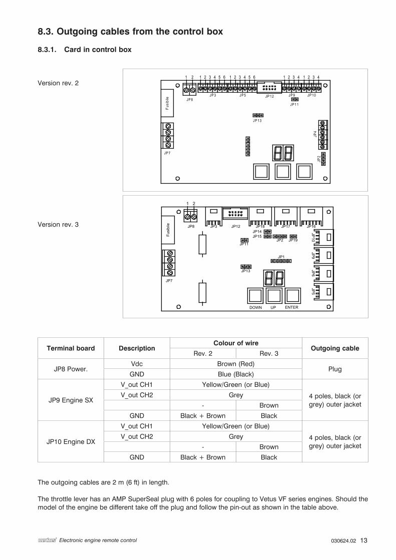
8.3. Outgoing cables from the control box
8.3.1. Card in control box
Version rev. 2
Version rev. 3
Terminal board DescriptionColour of wire
Outgoing cableRev. 2 Rev. 3
JP8 Power.Vdc Brown (Red)
PlugGND Blue (Black)
JP9 Engine SX
V_out CH1 Yellow/Green (or Blue)
4 poles, black (or grey) outer jacket
V_out CH2 Grey
- Brown
GND Black + Brown Black
JP10 Engine DX
V_out CH1 Yellow/Green (or Blue)
4 poles, black (or grey) outer jacket
V_out CH2 Grey
- Brown
GND Black + Brown Black
The outgoing cables are 2 m (6 ft) in length.
The throttle lever has an AMP SuperSeal plug with 6 poles for coupling to Vetus VF series engines. Should the model of the engine be different take off the plug and follow the pin-out as shown in the table above.
JP 8JP 3 JP 5 JP 9 JP 10JP 12
JP 11
JP 13
JP 7
JP4
JP2
1 2 3 4 5 6 654321 1 2 3 4 43211 2
Fusi
bile
JP12
UPDOWN ENTER
JP1
JP2
JP7
Fusi
bile
JP13
JP11
JP14JP15
JP19
21
JP8 JP3 JP18 JP17 JP16
JP10
JP9
JP6
JP5

14 030624.02 vetus®Electronic engine remote control
8.3.2. Relay card
Relay right engine
Relay left engine
Version for electronic engine with solenoid gearshift and trim
System for electronic engine with mechanical gearshift and trim
1.1 5.1 Forward (black 1) Trim down (black)
1.2 5.2
1.3 5.3 Vdc (black) Vdc (brown)
2.1 6.1 Reverse (black 2) Trim up (grey)
2.2 6.2
2.3 6.3
3.1 7.1 Trim down (black 1) Trailer (yellow/green)
3.2 7.2
3.3 7.3 Vdc (black)
4.1 8.1 Trim up (black 2) -
4.2 8.2 -
4.3 8.3
Connections to the electrically operated gearbox and the trim.
The outgoing cable from the control box for operating both the trim and the electrically operated gearbox has 3 poles (colours as shown in the table) and the mantle is black The length is 2 m (6 ft).
Power supply
Rel
ay 1
Rel
ay 2
Rel
ay 3
Rel
ay 4
Rel
ay 5
Rel
ay 6
Rel
ay 7
Rel
ay 8
Vdc (brown)
Forward (grey)Trim + (grey)
Trim - (black)Reverse (black) Reverse/ Trim -Forward/ Trim +

030624.02 15vetus® Electronic engine remote control
9. Programming
9.1. Keyboard for programming
NB: the control boxes and the operating levers must be set to neutral in order to be able to access the program-ming of the installation and thus also in order to set the parameters.
NB: the control boxes are already programmed in the factory and it should not be necessary to make changes to the parameters of the installation.
The keyboard is a display with two figures and three programming keys.
Colour of key Reference
Red 1 (-)
Yellow 2 (+)
Grey 3 (↵)
The display can show three different texts depending on the programme mode: - MENU (display is on constantly) - PROGRAMMING (display flashes) - DISPLAY (display is on constantly)
MENU In mode MENU the display is on constantly and it is possible to move from one parameter to the other using the keys ‘1’ and ‘2’. Pressing keys ‘1’ and ‘2’ switches to mode MENU from mode DISPLAY. Pressing key ‘3’ when in mode PARAMETERS also switches to mode MENU.
PROGRAMMING The display flashes when in mode PROGRAMMING and the value of the selected parameter can be changed by using the keys ‘1’ en ‘2’.
Pressing ‘3’ when in mode PROGRAMMING reverts the system to mode MENU and saves the value given to the parameter.
If key ‘3’ is not pressed within one minute to confirm a change to a parameter then mode PROGRAMMING will be exited and the parameter retains the value from before the change. Mode PROGRAMMING is accessed by holding keys ‘1’ and ‘2’ pressed in while switching the system on.
DISPLAYThe viewer automatically goes to mode DISPLAY (_ _) if no key is pressed for two minutes. The functioning of the installation is shown in mode DISPLAY. Mode Display consists of a series that repeats one or two series of data continuously. It is possible to access mode DISPLAY at any time by pressing keys ‘1’ and ‘2’ simultaneously
After power up, the disply shows a sequence of 2 codes: ‘FI’ and ‘XX’: ‘FI’ means FIRMWARE; ‘XX’ is the firmware version.

16 030624.02 vetus®Electronic engine remote control
10. Installations with electronically operated engine and mechanically operated gearbox.
10.1. Fitting the push-pull cable See Chapter 7 of this manual for how to fit the push-pull cable.
10.2. Setting the parameters It is necessary to set the outgoing minimum and maximum voltage values for installations with an electronically operated engine. The stroke of the gearbox requires mechanical setting.
Parameters to be set for installations with one engine.
Parameters to be set Display ValuesFactory values
Value on display
Reverse 0L Positions to be set for the push-pull cable in accordance with the procedure
in Chapter 10.2.1Neutral (*) 0F
Forward 0H
Throttle lever – minimum channel 1 L1
0 - 5 Vdc
0.9 9
Throttle lever – maximum channel 1 H1 4.3 43
Begin point of acceleration channel 1 C1 00 00
Throttle lever – minimum channel 2 L2 0.5 5
Throttle lever – maximum channel 2 H2 2.1 21
Begin point of acceleration channel 2 C2 00 00
Parameters to be set for installations with two engines.
Parameters to be set Display ValuesFactory values
Value on display
Right-hand engine - Reverse 0L
Positions to be set for the push-pull cable in accordance with the procedure
in Chapter 10.2.1
Right-hand engine – Neutral (*) 0F
Right-hand engine – Forward 0H
Left-hand engine- Reverse IL
Left-hand engine – Neutral (*) IF
Left-hand engine - Forward IH
Left-hand engine - Throttle lever – minimum channel 1 L1
0 - 5 Vdc
0.9 9
Left-hand engine - Throttle lever – maximum channel 1 H1 4.3 43
Begin point of acceleration channel 1 C1 00 00
Left-hand engine - Throttle lever – minimum channel 2 L2 0.5 5
Left-hand engine - Throttle lever – maximum channel 2 H2 2.1 21
Begin point of acceleration channel 2 C2 00 00
Right-hand engine - Throttle lever – minimum channel 3 L3 0.9 9
Right-hand engine - Throttle lever – maximum channel 3 H3 4.3 43
Begin point of acceleration channel 3 C3 00 00
Right-hand engine - Throttle lever – minimum channel 4 L4 0.5 5
Right-hand engine - Throttle lever – maximum channel 4 H4 2.1 21
Begin point of acceleration channel 4 C4 00 00
(*) factory values that cannot be changed
NB: it is advisable to check that the gearbox can be engaged for forward before setting the stroke of the control box, so that you can check whether forward is engaged when the push-pull cable is pushed or pulled.

030624.02 17vetus® Electronic engine remote control
10.2.1. Mechanical setting of the stroke of the gearbox
NB: check before switching on for the first time that the power supply to the control box is connected after the engine ignition lock.
The procedure to be carried out is as follows. 1. Switch on the engine and the control box by holding keys ‘1’ and ‘2’ pressed in simultaneously. 2. The control box changes automatically to the auto-learn mode and the first parameter to be set is shown
on the display. 3. Pressing key ‘3’ causes the display to flash and keys ‘1’ or ‘2’ can be used to move the push-pull cable
in the direction of the position required. 4. When the position has been reached press key ‘3’ to save the position in the memory. 5. Press key ‘1’ or ‘2’ to move through the menu and select the next parameter. 6. Repeat the procedure described in point 3 for all other parameters. 7. Switch off the control box after all parameters have been set.
N.B. 1: the procedure described has an operational nature and must therefore be carried out while the engine is running and the vessel is sailing. It is important to pay the greatest attention to the settings for forward and reverse in order to prevent sudden or uncontrolled movements of the vessel. If necessary ask for help from a second person who can switch the engine on and off as required.
NB: 2: stern drive and outboard engines: if it is not possible to set the strokes when the engine is running so that this has to be done when the vessel is not in the water, then simulate the rotation of the screws manually to make coupling the gearbox easier.
N.B. 3: if the strokes of the gearbox are known it is sufficient to physically measure the movement of the cursor on the control box in the various positions to be set.
Resetting the installation All positions have now been set. In order to return to normal functioning mode the operating station must be switched off and then switched on again.
10.2.2. Specific parameters As well as setting the strokes it is also possible to set other specific parameters for installations with throttle lever and mechanical gearbox. The installation will function properly for most of these applications with the factory settings. Therefore, it is not necessary to change other parameters.
Follow the procedure given below to set specific parameters. 1. Switch on the control box (the display shows _ _) and press keys ‘1’ and ‘2’ simultaneously after which
the value A0 will be displayed. 2. The display will flash after key ‘3’ is pressed. It is now possible to alter the value of the selected param-
eter by pressing key ‘1’ or ‘2’ until the selected value is reached. 3. Save the value set in the memory with key ‘3’. 4. Use keys ‘1’ and ‘2’ to move through the menu to set different values. Once you have reached the value
you require follow the detailed procedure given in point 3.
NB: changing factory values could cause the system to malfunction. Therefore, it is advisable not to change them unless our technician advises this.
List of the parameters
Code display Description Values Factory valueValue on display (factory value)
dIDelay before disengaging the gearbox
0 .. 9.9 s 0.0 s 0
dA Delay on the throttle lever 0 .. 9.9 s 0.0 s 0

18 030624.02 vetus®Electronic engine remote control
10.3 Setting values for the outgoing voltages
The procedure is as follows.1. Switch on the control box by holding keys ‘1’ and ‘2’ pressed in simultaneously. 2. The first parameter to be set is displayed automatically. 3. Use keys ‘1’ or ‘2’ to move through the parameters until the parameter to be set is displayed. 4. The display will flash after key ‘3’ is pressed. The parameter values can be changed using key ‘1’ or
‘2’. 5. Press key ‘3’ after setting the required value to save it in the memory. 6. Press key ‘1’ or ‘2’ to move through the menu and select the following parameter. 7. Repeat procedure under point 3 for all other parameters. 8. Switch the control box off after setting the parameters.
NB: this procedure applies to installations both with one or two engines.
Important: changing factory values could cause the system to malfunction. Therefore, it is advisable not to change them unless our technician advises this.
Code for the value Description
L* Signal minimum voltage *
H* Signal maximum voltage *
C* Signal begin point of throttle *
C*
H*
L*
V
Stroke lever

030624.02 19vetus® Electronic engine remote control
11. Control box for installations with electronically operated engine and electrically operated gearbox
11.1. Operating electrically operated gearbox
The gearbox is operated by means of the digital outputs on the relay card. Each gearbox has two separate operating controls for forward and reverse. Four outputs are available on the relay card:
- two for operating the right-hand gearbox- two for operating the left-hand gearbox
Parameters
A delay between switching directions can be set for installations with an electrically operated gearbox. This delay can be set with the following parameters:
Display Description Standard
dI Delay in switching off the gearbox 0.0 s
dA Delay in start of throttle 0.3 s
dFDelay in neutral; that is the delay in changing from forward to reverse or from reverse to forward. This delay does not occur when switching from neutral.
0.5 s
11.2. Setting values for the outgoing voltages See Paragraph 10.3 of this manual for how to set the parameters for operating the electronic throttle.
11.3. Cabling of the outgoing cables from the control box
Important: for installations with only one engine use the outputs that are for the starboard engine.
+12 VFuse
ThrottleTrim Gearbox CANbus
Sta
rboa
rd
engi
neP
orts
ide
engi
ne
ThrottleTrim Gearbox

20 030624.02 vetus®Electronic engine remote control
12. Option
12.1. Operating trimOperating the trims can be activated directly from the operating station using the buttons ‘+’ and ‘-’. The operating signals are sent to the control box from the operating station. The relay card fitted on the control box activates the ‘trim-in’ and ‘trim-out’-functions. For installations with two engines the buttons on the right-hand side in the Syncro mode operate the trims of both engines simultaneously.
Version for two engines Version for one engine
12.2. Electrical cables and plugs
12.2.1. Cables for electronically operated engine
This cable is used to connect the control box with the electronically operated engine. Code: 4649/EC3E*M (* this is the length of the cable in metres)
12.2.2. Trim cables / electrically operated gearbox
Code: 4649/EC3T*M (* this is the length of the cable in meters)This cable is used to connect the control box with the trim control (pump).
Code: 4649/EC3G*M (* this is the length of the cable in meters)This cable is used to connect the control box with the electrically operated gearbox.
Yellow/Green
Brown
Black
Grey
Black
Black 2
Black 1

030624.02 21vetus® Electronic engine remote control
12.2.4. T-plug for an extra operating station
This plug is used if extra operating stations are to be added to the system.Code: 4649/CANT
13. Behaviour of installation in the event of irregularities
13.1. Unforeseen switching off of the engines In all situations when the engines switch off without the operating levers being in neutral the system will behave as follows the next time that it is switched on.
a. The control box will set the gearbox to the safe position, that is the gearbox will be set to neutral and the throttle lever to minimum.
b. The operating station that controlled the vessel will be switched off.
Follow the procedure given in Paragraph 3.3 ‘Taking over control’ in order to switch the system that controlled the vessel back on.
13.2. Faults in the electrical network If there should be a fault in the electrical network the vessel can be controlled in an emergency by using the levers for this that are fitted on the control box. See the procedure ‘Emergency levers’ in Paragraph 4.2 of this manual.

22 030624.02 vetus®Electronic engine remote control
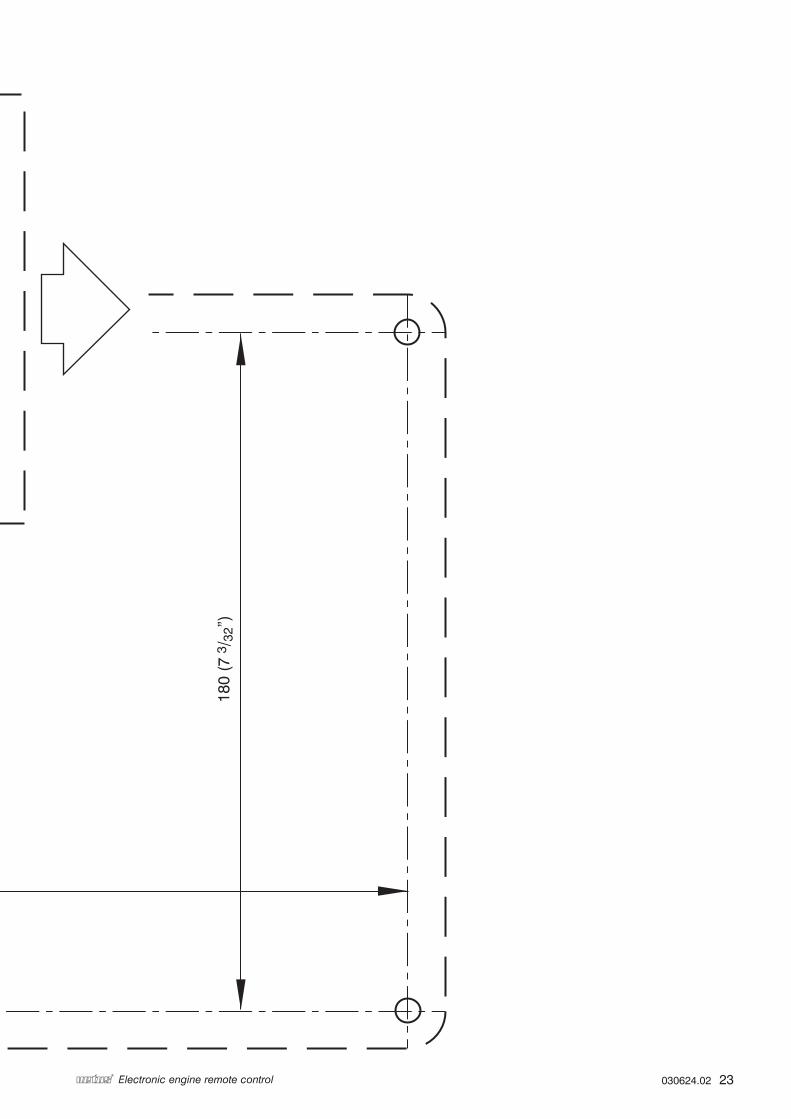
14. Drill pattern
180
(7 3
/ 32”
)
ø 6,2 (1/4”) 4 x
300 (11 13/16”)
65 (
2 9 /
16”)
95 (3 3/4”)
26,4
(1
1 /32
”)
24 (15/16”) ø 15,5 (5/8”)
ø 5,5 (7/32”) 4 x
030624.02 23vetus® Electronic engine remote control
180
(7 3
/ 32”
)
ø 6,2 (1/4”) 4 x
300 (11 13/16”)
65 (
2 9 /
16”)
95 (3 3/4”)
26,4
(1
1 /32
”)
24 (15/16”) ø 15,5 (5/8”)
ø 5,5 (7/32”) 4 x

vetus n.v.FOKKERSTRAAT 571 - 3125 BD SCHIEDAM - HOLLAND - TEL.: +31 10 4377700TELEFAX: +31 10 4372673 - 4621286 - E-MAIL: [email protected] - INTERNET: http://www.vetus.com
Printed in the Netherlands030624.02 09-08