electronic emission noticessupport.pcpartner.com/support/man/via/pa14.pdf• compliant with 1394...
TRANSCRIPT

1
Electronic Emission Notices
Federal Communications Commission (FCC) StatementThis equipment has been tested and found to comply with the limits for a Class B digitaldevice, pursuant to Part 15 of FCC Rules. These limits are designed to provide reasonableprotection against harmful interference in a residential installation. This equipmentgenerates, uses and can radiate radio frequency energy and, if not installed and used inaccordance with instructions contained in this manual, may cause harmful interferenceto radio and television communications. However, there is no guarantee that interferencewill not occur in a particular installation.
If this equipment does cause harmful interference to radio or television reception, whichcan be determined by turning the equipment off and on, the user is encouraged to try tocorrect the interference by one or more of the following measures:
- REORIENT OR RELOCATE THE RECEIVING ANTENNA- INCREASE THE SEPARATION BETWEEN THE EQUIPMENT AND THE RECEIVER- CONNECT THE EQUIPMENT INTO AN OUTLET ON A CIRCUIT DIFFERENT FROM
THAT OF THE RECEIVER- CONSULT THE DEALER OR AN EXPERIENCED AUDIO/TELEVISION TECHNICIAN
NOTE: Connecting this device to peripheral devices that do not comply with Class Brequirements, or using an unshielded peripheral data cable, could also result inharmful interference to radio or television reception.
The user is cautioned that any changes or modifications not expressly approvedby the party responsible for compliance could void the user’s authority to operatethis equipment.
To ensure that the use of this product does not contribute to interference, it isnecessary to use shielded I/O cables.
CopyrightThis manual is copyrighted with all rights reserved. No portion of this manual may becopied or reproduced by any means.
While every precaution has been taken in the preparation of this manual, no responsibilityfor errors or omissions is assumed. Neither is any liability assumed for damages resultingfrom the use of the information contained herein.
TrademarksAll brand names, logos and registered trademarks mentioned are property of theirrespective owners.

2
Technical Reference Booklet
Table of Contents
HARDWARE CONFIGURATION ....................................................... 4
Key Features ............................................................................................... 4
MOTHERBOARD LAYOUT ................................................................ 7
REARPANEL ..................................................................................... 8
JUMPER SETTING ............................................................................... 10CPU Speed Selection ................................................................................. 10JBAT1 - CMOS Clear ................................................................................... 10
CONNECTORS ................................................................................. 11Floppy Disk Drive Connector:CN3 .............................................................. 11
Hard Disk Connectors:CN1&CN2 .............................................................. 11Serial ATA Hard Disk Connectors:SATA1&SATA2 ........................................ 12USB Connectors :USB1/USB2/USB3 ......................................................... 13
Fan Power Connectors:FAN1/FAN2/WOL ................................................... 14AUX-IN Connector:AUX1 ............................................................................. 15CD-IN Connector:CDS1 .............................................................................. 15S-Bracket (SPDIF)/LEN/LFE/Surround Output Connector:
CN9(optional) .............................................................................................. 16Front Panel Audio Header:CN21 ................................................................ 18IEEE1394 Connectors:IEEE1&IEEE2 ......................................................... 19
Front Panel Header:FP1 ............................................................................. 21
SLOTS .............................................................................................. 22
CPU INSTALLATION ........................................................................ 23
HARDWARE SETUP ......................................................................... 26To Install DDR DIMMs ................................................................................. 26

3
BIOS SETUP ..................................................................................... 27Starting Setup .............................................................................................. 27Main Menu ................................................................................................... 28Standard CMOS Features ........................................................................... 29
Advanced BIOS Features ............................................................................ 30Advanced Chipset Features ........................................................................ 30Integrated Peripherals ................................................................................ 30
Power Management Setup .......................................................................... 30PNP/PCI Configurations ............................................................................. 30PC Health Status ......................................................................................... 30
Frequency/Voltage Control .......................................................................... 31Set Supervisor/User Password .................................................................. 31Flash Update Procedure ............................................................................. 32
APPENDIX ....................................................................................... 32

4
Technical Reference Booklet
HARDWARE CONFIGURATION
Key Features :Chipset
• VIA K8T800/K8M800+VT8237 chipset.
Processor• Support for AMDTM K8/ClawHammerTM Processor.• Supports AMD AthlonTM 64 processor.• Processor interface via HypertransportTM bus.
VRM 9.0(Voltage Regulator Modules) On board• Flexible motherboard design with on board VRM 9.0, easy to upgrade
with future processors.
System Memory• A total of two 184-pin DDR SDRAM sockets.• Supports DDR400/DDR333/DDR266/DDR200 SDRAM.• DRAM devices that are 4,8 and 16 bits wide.• DIMM sizes from 64 Mbytes to 2Gbyte.• 2.5V DRAM interface for DDR SDRAM.
System BIOS• PnP, APM, ATAPI and Windows® 98/2000/XP.• Full support of ACPI & DMI.• Auto detects and supports LBA harddisks with capacities over 8.4GB.• Easy to upgrade BIOS by end-user.
On-board VGA (optional)• 8/16/32/64 MB frame buffers using system memory.• Internal AGP 8x equivalent performance.• Graphics engine clock up to 200 MHz decoupled from memory clock.• High quality DVD video playback.• 128-bit 2D graphics engine.• 128-bit 3D graphics engine.

5
On-board I/O• On board two PCI fast IDE ports supporting up to 4 ATA, ATA2 , Ultra
ATA33/ 66/100/133 IDE HDDs, CD-ROMs, ZIP drives and LS-120drives as boot drive.
• One ECP/EPP parallel port.• Two 16550 Compatible UART serial ports.(One port via a header)• One floppy port supports two FDD of 360KB, 720KB, 1.2MB , 1.44MB
and 2.88MB capacity.• Eight USB2.0 ports.• PS/2 keyboard connector.• PS/2 mouse is supported.• One Front Panel Sound Connector.• Infrared (IrDA) is supported via a header.
Expanded USB Support• Includes 4 UHCI host controllers,increasing the number of external
ports to eight.• Includes 1 EHCI USB2.0 Host Controller that supports eight ports
(Bandwidth shared between eight ports).
Full Featured Accelerated Graphics Port (AGP)• Supports AGP3.0 including 4X/8X AGP card.• AGP 1.5V connector support only.• High priority access support.
Plug-and-Play• Supports Plug and Play specification 1.1.• Plug and Play for Windows® 98, Windows® 2000 as well
as Windows® XP.• Fully steerable PCI interrupts.
On-board AC97 Sound(optional)• Integrated AC97 controller with standard AC97 Codec.• Direct Sound and Sound Blaster compatible.• Full-Duplex 16-bit record and play back.• PnP and APM 1.2 support.• Windows® 98/2000/XP drivers ready.• Line-in, Line-out, Mic-in and MIDI/Game port.• Supports ALC650 AC97 Code for six sound channel
output (optional).
Hardware Configuration

6
Technical Reference Booklet
Integrated serial ATA/RAID Controller.(optional)• Independent DMA operation on two ports.• Data transfer rate 150Mb/s.• SATA devices can be configured in multiple RAID configurations-
supports RAID Level0,RAID Level1 and JBOD.
On-board VT6103 LAN (optional)• High performance PCI master interface with scatter / gather and
bursting capability.• Standard MII interface to external PHYceiver.• 10/100MHz full and half duplex operation.
Power Management• Supports SMM, APM and ACPI.• Break switch for instant suspend/resume on system operations.• Energy star “Green PC” compliant.• Hardware monitoring circuit is supported, provide voltage,
temperature, fan speed, etc. monitoring (optional).• WOL (Wake-On-Lan) header support.• Supports suspend-to-RAM(STR)(optional).
On-board IEEE1394(optional)• Compliant with 1394 open HCI specifications v1.0 and v1.1.• Integrated 400Mbit 2 port PHY.
Expansion Slots• 1 AGP slot (support AGP 3.0-8X).• 5 PCI bus master slots - ver. 2.1 compliant.
Static electricity can harm delicate components of the motherboard.To prevent damage caused by static electricity, discharge the staticelectricity from your body before you touch any of the computerselectronic components.

7
Motherboard Layout (35-AA14-X0-XX)The following diagrams show the relative positions of the jumpers, connectors, majorcomponents and memory banks on the motherboard.
NOTE1) Be sure to check the cable orientation in order to match the colored strip to the pin
1 end of the connector.2) When you start up the system, please wait for 5 seconds after you power on AC.3) It is not recommended to add a metal spacer plate on the back of the Socket754.
Otherwise, some components will be short and damaged.
# The LAN ,Video Out and IEEE1394 Connectors are optional.# The ALC650 embeds an internal analog switch (by driver software) to share
LINE input with Surround output, and share MIC input with CENTER/LFEoutput.
Motherboard layout

8
Technical Reference Booklet
Rear Panel The back panel provides the following connectors:
Mouse Connector The mainboard provides a standard PS/2® mouse mini DIN connector forattaching a PS/2® mouse.You can plug a PS/2® mouse directly into thisconnector.
Keyboard Connector The mainboard provides a standard PS/2® keyboard mini DIN connectorfor attaching a PS/2® keyboard.You can plug a PS/2® keyboard directly intothis connector.
USB 2.0 Connector The mainboard provides a UHCI (Universal Host Controller Interface)Universal Serial Bus root for attaching USB devices such as keyboard, mouseor other USB-compatible devices.You can plug the USB device directly intothe connector.
PIN SIGNAL DESCRIPTION
1 VCC +5V/5VSB (optional)2 -Data 0 Negative Data Channel 03 +Data0 Positive Data Channel 04 GND Ground5 VCC +5V/5VSB (optional)6 -Data 1 Negative Data Channel 17 +Data 1 Positive Data Channel 18 GND Ground
USB 2.0 Connector DescriptionUSB 2.0 Connector
9
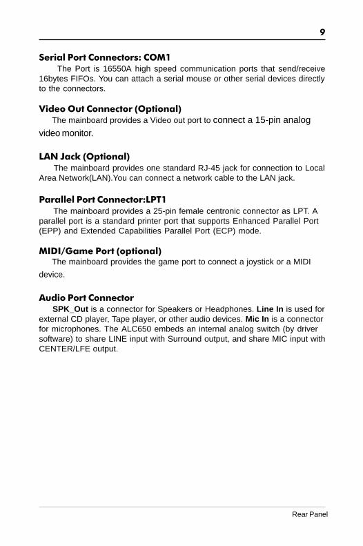
Serial Port Connectors: COM1 The Port is 16550A high speed communication ports that send/receive16bytes FIFOs. You can attach a serial mouse or other serial devices directlyto the connectors.
Video Out Connector (Optional)The mainboard provides a Video out port to connect a 15-pin analog
video monitor.
LAN Jack (Optional) The mainboard provides one standard RJ-45 jack for connection to LocalArea Network(LAN).You can connect a network cable to the LAN jack.
Parallel Port Connector:LPT1 The mainboard provides a 25-pin female centronic connector as LPT. Aparallel port is a standard printer port that supports Enhanced Parallel Port(EPP) and Extended Capabilities Parallel Port (ECP) mode.
MIDI/Game Port (optional)The mainboard provides the game port to connect a joystick or a MIDI
device.
Audio Port Connector SPK_Out is a connector for Speakers or Headphones. Line In is used forexternal CD player, Tape player, or other audio devices. Mic In is a connectorfor microphones. The ALC650 embeds an internal analog switch (by driversoftware) to share LINE input with Surround output, and share MIC input withCENTER/LFE output.
Rear Panel

10
Technical Reference Booklet
Jumper SettingsThis chapter explains how to configure the motherboard’s hardware. Before using yourcomputer, make sure all jumpers and DRAM modules are set correctly. Refer to thischapter whenever in doubt.
CPU Speed SelectionIn this motherboard, jumperless feature is implemented such that no jumper is required tobe set for different type of CPU installed.
Notice :1. Be sure to save the CMOS setting when exit the CMOS.2. If the CPU is frequency multiplier locked, no CPU speed change will be seen
even if the frequency multiplier setting in CMOS setup is changed.
JBAT1 - CMOS ClearJBAT1 Selection
1-2* Normal*
2-3 CMOS Clear
1JBAT1
Close Open * = Default setting.

11
Connectors
The mainboard provides connectors to connect to FDD, IDE HDD,Serial ATA Hard Disk,USB devices, CPU/PWRFAN/WOL ,etc.
Floppy Disk Drive Connector:CN3The mainboard provides a standard floppy disk drive connector that
supports 360K, 720K, 1.2M, 1.44M and 2.88M floppy disk types.
Hard Disk Connectors:CN1&CN2The mainboard has a 32-bit Enhanced PCI IDE and Ultra DMA 33/66/100/
133controller that provides PIO mode 0~4, Bus Master, and Ultra DMA 33/66/100/133function. You can connect up to four hard disk drives, CD-ROM, 120MBFloppy (reserved for future BIOS) and other devices.
CN1 (Primary IDE Connector)The first hard drive should always be connected to IDE1.IDE1 can connect
a Master and a Slave drive.You must configure second hard drive to Slavemode by setting the jumper accordingly.
CN2 (Secondary IDE Connector)IDE2 can also connect a Master and a Slave drive.
CN
2
CN3
CN
11
1
1
Connectors

12
Technical Reference Booklet
Serial ATA Hard Disk Connectors: SATA1&SATA2(Optional)
The mainboard has 2 SATA connectors. The mainboard provides optionaldual high-speed Serial ATA interface ports, SATA1,SATA2 Each supports 1st
generation serial ATA data rates of 150 MB/s. Both connectors are fully compliantwith Serial ATA 1.0 specifications. Each Serial ATA connector can connect to 1hard disk device. Please refer to Serial ATA Raid manual for detail softwareinstallation procedure.
PIN SIGNAL
1 GND2 TXP3 TXN4 GND5 RXN6 RXP7 GND
SATA1&SATA2
SAT
A1
SAT
A2

13
12
910
12
910
USB1 USB2
PIN Assignment
1 VCC2 VCC3 USBP0-4 USBP1-5 USBP0+6 USBP1+7 GND8 GND9 KEY10 OC#
USB Connector
USB Connectors: USB1/USB2/USB3This mainboard has USB ports. Some computer cases have a special
module that mounts USB ports at the front of the case. If you have this kindof case, use auxiliary USB connector USB1/USB2/USB3 to connect thefront mounted ports to the mainboard.
12
910
USB3
Connectors

14
Technical Reference Booklet
Fan Power Connectors:FAN1&FAN2The FAN1 (processor fan), FAN2 (system fan) support system cool-ing
fan with +12V.It supports three-pin head connector. When connecting thewire to the connectors, always take note that the red wire is the positive andshould be connected to the +12V, the black wire is Ground and should beconnected to GND. If the mainboard has a System Hardware Monitor chipseton-board, you must use a specially designed fan with speed sensor to takeadvantage of the CPU fan control.
FAN2
FAN1
1
1
1
WOL
WOL: Wake On LANIf you have installed a LAN card, use the cable provied with the card to plug
into the mainboard WOL connector. This enables ables the Wake On LAN(WOL) feature. When your system is in a power-saving mode, any LAN signalautomatically resumes the system.You must enable this item using the PowerMannagement page of the Setup Utility.

15
AU
X1
CD
S1
11
PIN Assignment1 CD-L2 GND3 GND4 CD-R
CDS1 : CDS1
AUX1 : AUX1
PIN Assignment1 AUX-L2 GND3 GND4 AUX-R
AUX-IN Connector:AUX1The connector is for Audio Device.
CD-IN Connector:CDS1The connector is for CD-ROM Drive.
Connectors

16
Technical Reference Booklet
S-Bracket(SPDIF)/CEN/LFE/Surround Output Connector:CN9 (optional)
The connector allows you to connect a S-Bracket for a Digital Interface(SPDIF). The S-Bracket offers 1 SPDIF jacks for digital audio transmissionand 2 analog Line-Out jacks for other 4-channel audio output. So you can useLine in, Mic in and 6 channel audio output features at the same time.
CN9
2
1
109

17
Connectors
PIN SIGNAL DESCRIPTION
1 SOUT-L Audio left surrounding output2 SOUT-R Audio right surrounding output3 GND Ground4 GND Ground5 CET-OUT Audio center output6 LFE-OUT Audio bass output7 GND Ground8 SPDIF S/PDIF input9 (No Pin) Key10 SPDFO S/PDIF output
CN9-S-Bracket
S-Bracket Cable (optional)
Connect to CN9
SPDIF jack (coaxial)Analog Line-Out jack

18
Technical Reference Booklet
Front Panel Audio Header: CN21This mainboard supports front panel microphone and speaker out ports.
If your computer case has these ports,connect them to CN21.
PIN Assignment
1 MIC2 GND3 REF4 POWER5 Front Audio(R)6 Rear Audio(R)7 Reserved8 Key(No pin)9 Front Audio(L)10 Rear Audio(L)
CN21
Note:If you want to use “Front Audio” connector, you must move 5,6,9,10 jumper.In order to utilize the front audio header, your chassis must have frontaudio connector. Also please make sure the pin assignment on the cableis the same as the pin assignment on the MB header. To find out if thechassis you are buying support front audio connector, please contractyour dealer.
CN2110
9
2
1

19
IEEE 1394 Connectors: IEEE1&IEEE2 (optional)The mainboard provides two 1394 pin headers that allow you to connect
IEEE 1394 ports.
1
2
9
10
IEEE1 IEEE21
2
9
10
Connectors
20
Technical Reference Booklet
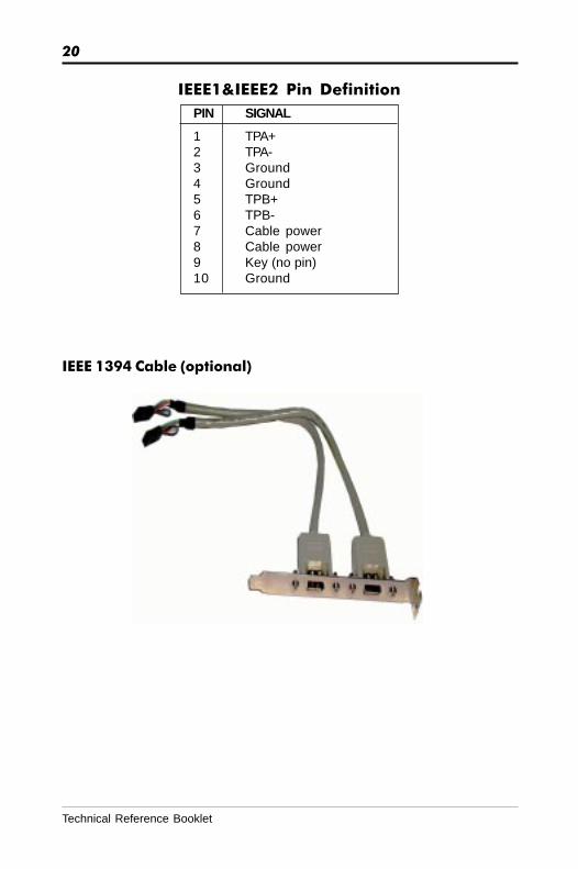
PIN SIGNAL
1 TPA+2 TPA-3 Ground4 Ground5 TPB+6 TPB-7 Cable power8 Cable power9 Key (no pin)10 Ground
IEEE1&IEEE2 Pin Definition
IEEE 1394 Cable (optional)

21
Front Panel Header: FP1The mainboard provides one front panel connector for electrical connecti
-on to the front panel switches and LEDs.
FP1
NC
VCC
KEY
NCGND
IRRXSPEAKER
GNDKEY
IRTX
NC
VCC
GND
KEYGND
PWR_SWRESET
NCKEY
GNDPW_LED-PW_LED+
HDD_LED-HDD_LED+
24 23
161718
2022 21
19
1513
7
119
531
14
681012
24
Connectors

22
Technical Reference Booklet
SlotsThe motherboard provides one AGP slot,five 32-bit PCI bus slots.
AGP Slot
PCI Slots
AGP (Accelerated Graphics Port) SlotThe AGP slot allows you to insert the AGP graphics card. AGP is an inter-
face specification designed for the throughput demands of 3D graphics. Itintroduces a 66MHz, 32-bit channel for the graphics controller.
PCI (Peripheral Component Interconnect) SlotsThe PCI slots allow you to insert the expansion cards to meet your needs.
When adding or removing expansion cards, make sure that you unplug thepower supply first. Meanwhile,read the documentation for the expansion cardto make any necessary hardware or software settings for the expansion card,such as jumpers, switches or BIOS configuration.

23
CPU InstallationPlease refer to the following steps to install the CPU.
1. Please turn off the power and unplug the power cord before installing the CPU. Pull the lever sideways away from the socket. Make sure to raise thelever up to a 90 degree angle.
2. Look for the gold arrow. The gold arrow should point towards the lever pivot.The CPU can only fit in the correct orientation.
2. If the CPU is correctly installed, the pins should be completely embeddedinto the socket and can not be seen. Please note that any violation of thecorrect installation procedures may cause permanent damages to yourmainboard.
CPU Installation

24
Technical Reference Booklet
4. Press the CPU down firmly into the socket and close the lever. As the CPUis likely to move while the lever is being closed, always close the lever withyour fingers pressing tightly on top of the CPU to make sure the CPU isproperly and completely embedded into the socket.
5. Position the CPU cooler set onto the CPU.

25
6. Use one end of the clip to hook the latch of the CPU sliding plate and thenhook the other three latch to fix the cooling fan set. At last, connect the fan tothe power supply connector provided on your mainboard.
CPU Installation

26
Technical Reference Booklet
Clip
ClipDDR DIMM
DDR DIMM Socket
Notch
Hardware SetupTo Install DDR DIMMs1. Locate the DDR DIMM sockets.2. Holding the DDR DIMM by the edges, remove it from its antistatic package.3. Make sure the clips at either end of the socket are pushed away from the socket.
4. Position the DDR DIMM above the socket. Align the notch in the bottomedge of the DDR DIMM with the keys in the socket.
5. Insert the bottom edge of the DDR DIMM into the socket.6. When the DDR DIMM is seated, push down on the top edge of the DDR DIMM until the
retaining clips at the ends of the socket snap into place. Make sure the clips arefirmly in place.
Please turn off system before installing and removing any
device, otherwise you’ll cause the system damage.
27
BIOS SetupThis chapter discusses Award’s Setup Program built into the ROM BIOS. The Setup
Program allows users to modify the basic system configuration. This special information
is then stored in battery-backed RAM, which retains the setup information when the
power is turned off.
Starting SetupThe Award BIOS is immediately activated when you turn on the computer. The BIOS
reads the system information contained in the CMOS and begins the process of checking
out the system and configuring it. When it finishes, the BIOS will seek an operating
system on one of the disks and then launch and turn control over to the operating
system.
While the BIOS is in control, the Setup Program can be activated :
1. By pressing <Del> immediately after switching the system on, or
2. By pressing the <Del> key when the following message appears briefly at
the bottom of the screen during the POST (Power On Self Test )
Press DEL to enter SETUP
If the message disappears before you can respond and you still wish to enter Setup,
restart the system to try again by turning it OFF then ON or pressing the “RESET” button
on the system case. You may also restart by simultaneously pressing the <Ctrl>, <Alt>,
and <Delete> keys. If you do not press the keys at the correct time and the system does
not reset, an error message will be displayed and you will again be asked to ...
PRESS F1 TO CONTINUE, DEL TO ENTER SETUP
Getting HelpPress F1 to pop up a small help window that describes the appropriate keys to use and
the possible selections for the highlighted item. To exit the Help Window press <Esc> or
the F1 key again.
In Case of ProblemsIf, after making and saving system changes with the Setup Program, you discover that
your computer does not reset, use the Award BIOS defaults to override the CMOS
settings.
BIOS Setup

28
Technical Reference Booklet
Main MenuOnce you enter the Award BIOS CMOS Setup Utility, the Main Menu will appear on thescreen. The Main Menu allows you to select from various setup functions and two exitchoices. Use the arrow keys to select among the items and press <Enter> to accept andenter the sub-menu.
Phoenix - Award BIOS CMOS Setup Utility
8 Standard CMOS Features 8 Frequency/Voltage Control8 Advanced BIOS Features Load Fail-Safe Defaults8 Advanced Chipset Features Load Optimized Defaults8 Integrated Peripherals Set Supervisor Password8 Power Management Setup Set User Password8 PnP/PCI Configurations Save & Exit Setup8 PC Health Status Exit Without Saving
Esc : Quit éêèç : Select ItemF10 : Save & Exit Setup
Time, Date, Hard Disk Type ... ...
(Note : The figures of BIOS Setup Menu included here only show a typicalcase, and may not be exactly the same as the one on your unit.)
Note that a brief description of each highlighted item will appear at the bottom of thescreen.
Standard This setup page includes all the items of Award™ special standardCMOS Features features.
Advanced BIOS This setup page includes all the items of Award™ special enhancedFeatures features.
Advanced This setup page includes all the items of chipset special features.Chipset Features
Integrated This section page includes all the items of IDE hard drive andPeripherals Programmed Input / Output features.
Power This entry only appears if your system supports PowerManagement Management “Green PC” standards.Setup
PnP/PCI This entry appears if your system supports PNP/PCI.Configurations
PC Health Status Display CPU and Case Fan Speed,etc.
Frequency/ CPU speed setting are settings of CPU speed. You should refer toVoltage Control your CPU marking.
Load Fail-Safe The BIOS defaults have been set by the manufacturer and representDefaults settings which provide the minimum requirements for your system
to operate.

29
Load Optimized The chipset defaults are settings which provide for maximumDefaults system performance. While Award has designed the
custom BIOS to maximize performance, the manufacturerhas the right to change these defaults to meet its needs.
Set Supervisor/ Changes, sets, or disables password. It allows you to limitUser Password access to the system and the Setup Program.
Save & Exit Saves value changes to CMOS and exits setup.Setup
Exit Without Abandons all CMOS value changes and exits setup.Saving
Standard CMOS FeaturesThe items in Standard CMOS Setup Menu are divided into 10 categories. Each categoryincludes one or more setup items. Use the arrow keys to highlight the item and then usethe <PgUp> or <PgDn> key to select the desired value in each item.
Phoenix - Award BIOS CMOS Setup UtilityStandard CMOS Features
Date (mm :d d : y y ) Wed. Jan 01 2003 Item HelpTime (h h :mm:ss) 11 : 1 : 35
Menu Level 8
8IDE Channel 0 Master [Press Enter 4303 MB]8IDE Channel 0 Slave [None] Change the day, month,8IDE Channel 1 Master [None] year and century8IDE Channel 1 Slave [None]8IDE Channel 2 Master [None]8IDE Channel 3 Master [None]
Drive A [1.44M, 3.5 in.]Drive B [None]
Video [EGA/VGA]Halt on [All,But Keyboard]
Base Memory 640KExtended Memory 30720KTotal Memory 31744K
éêèç : Move Enter : Select +/-/PU/PD : Value F10 : Save ESC : Exit F1 : General HelpF5 : Previous Values F6 : Fail-Safe Defaults F7 : Optimized Defaults
(Note : The figures of BIOS Setup Menu included here only show a typicalcase, and may not be exactly the same as the one on your unit.)
Date The date format is <day-of-the-week>. <month> <day> <year>.
Time The time format is <hour> <Minute> <second> displayed in24-hour military-time clock. For example, 1 p. m. is displayedas 13:00:00.
BIOS Setup

30
Technical Reference Booklet
IDE Channel These categories identify the types of the four channels that0/1/2/3 have been installed in the computer.
If the controller of the HDD interface is SCSI, the selection shallbe “None”.
Drive A / This category identifies the types of floppy disk drive A or driveDrive B B that has been installed in the computer.
Video The default setting is EGA/VGA.
Halt on You can select which type of error will cause the system to halt.
Advanced BIOS FeaturesThis section allows you to configure your system for basic operation. You have theopportunity to select the system’s default speed, boot-up sequence, keyboard operation,shadowing and security.
Advanced Chipset FeaturesThe Chipset Features Setup option is used to change the values of the chipset registers.These registers control most of the system options in the computer.
This section allows you to configure the system based on the specific features of theinstalled chipset. This chipset manages bus speeds and access to system memoryresources, such as DRAM and the external cache. It must be stated that these itemsshould not be altered. The default settings have been chosen because they provide thebest operating conditions for your system.
Integrated PeripheralsThe Integrated Peripherals Setup allows the user to configure the onboard IDE controller,floppy disk controller, the printer port and the serial ports.
Power Management SetupThe Power Management Setup Menu allows you to configure your system to most saveenergy while operating in a manner consistent with your own style of computer use.
PnP/PCI ConfigurationsThis section describes how to configure the PCI bus system. This section covers somevery technical items and it is recommended that only experienced users should makeany changes to the default settings.
PC Health StatusThe PC Health Status display CPU and Case Fan Speed, etc.

31
Frequency/Voltage ControlThis section allows you to set CPU Speed.
Set Supervisor/User PasswordYou can set either supervisor or user password, or both of them. The differencebetween them are:
Supervisor Password : You can enter the Setup Program and changethe options of the setup menus.
User Password : You can enter the Setup Program but can notchange the options of the setup menus.
When you select this function, the following message will appear at the center of thescreen to assist you in creating a password.
ENTER PASSWORD:
Type the password, up to eight characters in length, and press<Enter>. The new passwordwill clear the previously entered password from the CMOS memory. You will be asked toconfirm the password. Type the password again and press <Enter>. You may alsopress <Esc> to abort the selection and operate without a password.
To disable a password, just press <Enter> when you are prompted to enter the password.A message will be displayed to confirm that the password is disabled.
PASSWORD DISABLED.
Once the password is disabled, the system will reset and you can enter the SetupProgram freely.
When a password is enabled, you will be prompted to enter it every time you try to entersetup. This prevents an unauthorized person from changing any setting of your systemconfiguration.
In addition, when a password is enabled, you can require the BIOS to request a passwordevery time your system is rebooted. This would further prevent unauthorized use ofyour computer.
The password requirement is defined by the Security Option of the BIOS Features SetupMenu. If the Security Option is set to “System”, the password will be required both atresetting and at entering setup. If the option is set to “Setup”, the prompt only appearswhen you try to enter setup.
BIOS Setup

32
Technical Reference Booklet
Flash Update ProcedureA program AWDFLASH.EXE is included in the utility diskette or CD (X:\Utility\
AWDFLASH.EXE). The user is recommended to follow the procedure below to update
the flash BIOS.
(X: your CD driver letter).
1. Create a DOS-bootable floppy diskette. Copy the new BIOS file (just obtained or
downloaded) and the utility program AWDFLASH.EXE to the diskette.
2. Allow the PC system to boot from the DOS diskette.
3. At the DOS prompt, key in
AWDFLASHand hit <ENTER>
4. Enter the file name of the new BIOS.
5. The question: “Do you want to save BIOS (Y/N)?” is displayed.
Key in “N” if there is no need to save the existing BIOS content..Key in “Y” if a backup copy of the existing BIOS is needed.(A file name has to be assigned to the existing BIOS binary file.)
6. The message:press “Y” to program or “N” to exit is displayed.
Key in “Y”
7. Wait until the flash-update is completed.
8. Power down the PC system.
9. Restart the PC.
Warning:
DO not turn off or RESET the computer during the flash process.If you are unsure how to upgrade the BIOS, it is best to take yourcomputer to an Authorized Service Center and have a trainedtechnician do the work for you.
APPENDIX
Note to User:1.The bundled driver CD attached an Auto-Run feature for all the drivers
that the motherboard need. Please select the drivers that you want toinstall and click the button on the installation panel.2.This motherboard support USB2.0 feature only on Windows® 2000/XP OS.
0141A8