electronic control system single engine installation ... · electronic control system: single...
TRANSCRIPT
Electronic Control System: Single Engine Installation Manual for 6SY/8SY Engines Page 1
Electronic Control System Single Engine Installation Manual for 6SY/8SY Engines
MANINSYM01Revision 1.7
Electronic Control System: Single Engine Installation Manual for 6SY/8SY Engines Page 2
RECREATIONAL CRAFT DIRECTIVE 94/25/EC
This product has been designed to be compliant with the above Directive.Maximum performance, and compliance with the EMC Directive, can only be ensured by correct installation. It is strongly recommended that the installation conforms with the following standards:
APPLICABLE STANDARDSa) ISO 8846 Small Craft-Electrical Devices Protection against ignition of surrounding fl ammable gases.b) ISO = International Standards Organization
SAFE BOATING STATEMENTThis device meets or exceeds the applicable ABYC, ISO, and USCG safe boating rules, regulations, standards, and guidelines.
SAFE BOATING ON THE WEBU.S. Coast Guard www.uscg.milU.S. Power Squadron www.usps.org
The information contained in this manual is believed to be accurate at the time of going to print but no responsibility, direct or consequential, can be accepted for damage resulting from the use of this information. The manufacturers reserve the right to make changes, without notice, to any of its products.
NOTICE TO INSTALLER
The WARNINGS and CAUTIONS within this manual are used to alert the installer to hazards that exist concerning a particular service, operation or component. They also may convey special instructions to reduce
the risk of injury during the operation or servicing of the engine.
However, these safety alerts alone cannot eliminate the hazards that they signal. Strict compliance to these special instructions when performing installation, operation, and maintenance is the most effective accident
prevention measure along with exercising care and using common sense when performing such actions.
American Boat & Yacht Council (http:\\www.abycinc.org)
1. #15 Torx screw driver2. 2.5 inch (64mm) hole saw3. 3.0 inch (75mm) hole saw
Special Installation Tools Needed
Electronic Control System: Single Engine Installation Manual for 6SY/8SY Engines Page 3
Table of Contents
Components 4 Engine Room 4 Helm 5Cables 6NMEA 2000® CANBus Cables 8Mounting 9 Engine Room - Block Diagram Layout 9 Helm 10Connectivity 11 Engine Room 11 Engine Room to Helm 18 Helm 20Pre-Start Up Checklist 23Calibration 24 Start Up 26Digital Display 27Templates 29Appendix A: Contol Head Operation 41 Appendix B: Key Switch Panel Diagram(s) 43 Appendix C: Default Settings 45Appendix D: Transmission Wiring 46 Appendix E: Power Diagram 50 Appendix F: Trolling 52Appendix G: Deutsch Connector Insertion/Removal 55Appendix H: Miscellaneous 56
Electronic Control System: Single Engine Installation Manual for 6SY/8SY Engines Page 4
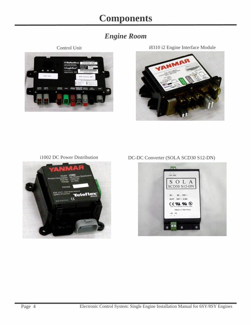
Components
Control Unit
i1002 DC Power Distribution
i8310 i2 Engine Interface Module
Engine Room
DC-DC Converter (SOLA SCD30 S12-DN)
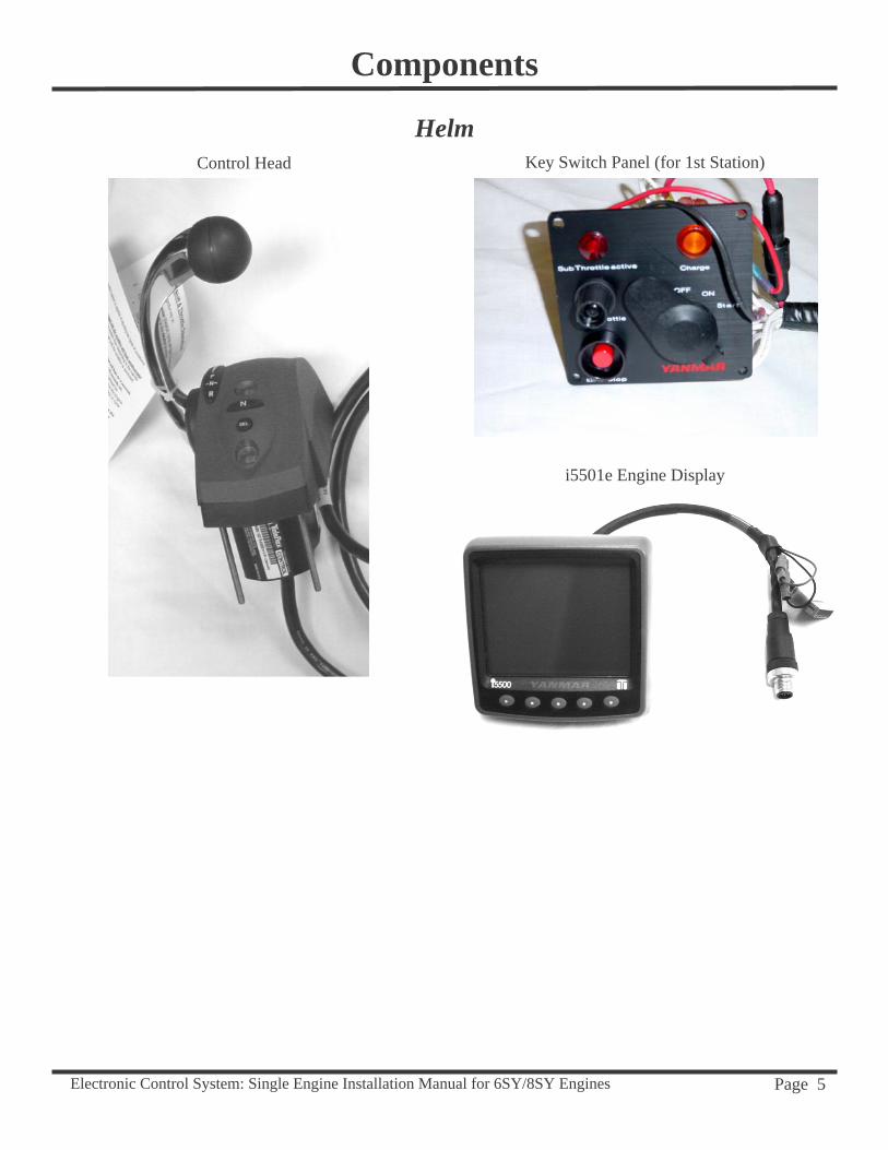
Electronic Control System: Single Engine Installation Manual for 6SY/8SY Engines Page 5
Helm
i5501e Engine Display
Key Switch Panel (for 1st Station)Control Head
Components
Electronic Control System: Single Engine Installation Manual for 6SY/8SY Engines Page 6
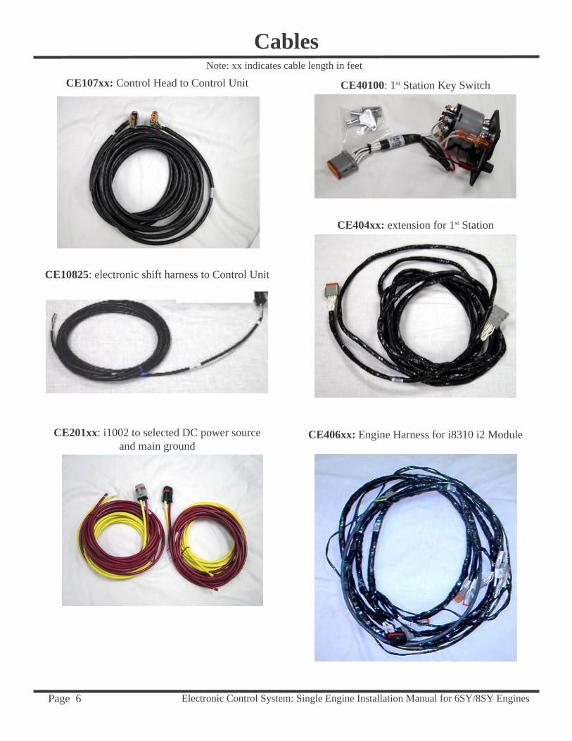
CE406xx: Engine Harness for i8310 i2 Module
CE404xx: extension for 1st Station
CE107xx: Control Head to Control Unit
CE10825: electronic shift harness to Control Unit
CablesNote: xx indicates cable length in feet
CE201xx: i1002 to selected DC power sourceand main ground
CE40100: 1st Station Key Switch

Electronic Control System: Single Engine Installation Manual for 6SY/8SY Engines Page 7
CablesCE41300: CANBus to DC-DC converter
(for CANBus power)
CE41200: “jumper-trans switch” (jumper for transmission circuit termination)
CE407xx: i1002 to CU and DC-DC Converter
CE408xx: i1002 to i8310 i2 Module
CE40900: i1002 to i8310 i2 Module
Electronic Control System: Single Engine Installation Manual for 6SY/8SY Engines Page 8
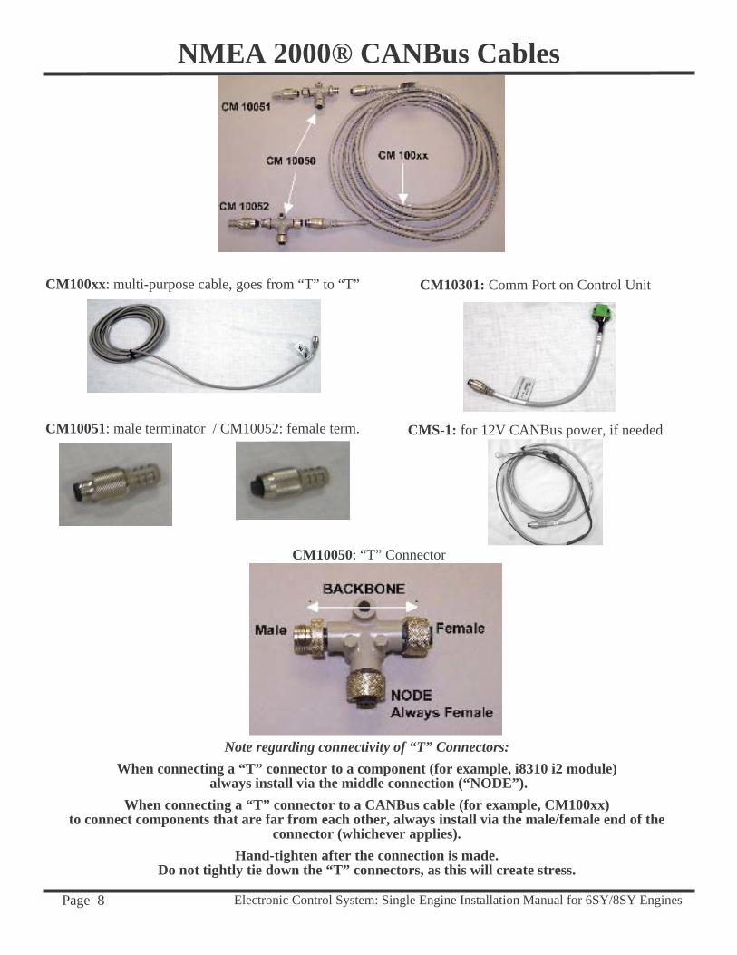
CM10050: “T” Connector
CM10051: male terminator / CM10052: female term.
NMEA 2000® CANBus Cables
CM100xx: multi-purpose cable, goes from “T” to “T”
CMS-1: for 12V CANBus power, if needed
CM10301: Comm Port on Control Unit
Note regarding connectivity of “T” Connectors:When connecting a “T” connector to a component (for example, i8310 i2 module)
always install via the middle connection (“NODE”). When connecting a “T” connector to a CANBus cable (for example, CM100xx)
to connect components that are far from each other, always install via the male/female end of the connector (whichever applies).
Hand-tighten after the connection is made.Do not tightly tie down the “T” connectors, as this will create stress.
Electronic Control System: Single Engine Installation Manual for 6SY/8SY Engines Page 9
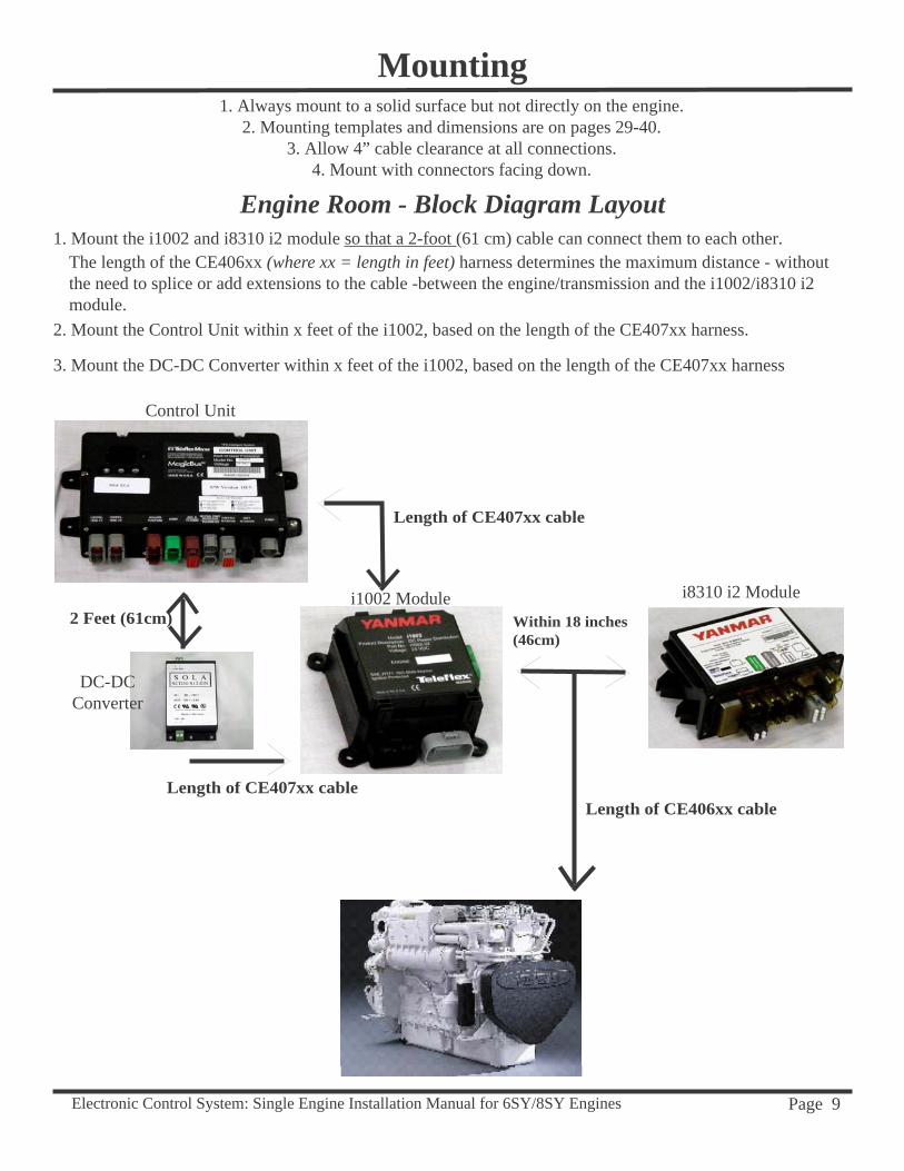
2. Mount the Control Unit within x feet of the i1002, based on the length of the CE407xx harness.
1. Mount the i1002 and i8310 i2 module so that a 2-foot (61 cm) cable can connect them to each other.The length of the CE406xx (where xx = length in feet) harness determines the maximum distance - without the need to splice or add extensions to the cable -between the engine/transmission and the i1002/i8310 i2 module.
3. Mount the DC-DC Converter within x feet of the i1002, based on the length of the CE407xx harness
Mounting
Engine Room - Block Diagram Layout
1. Always mount to a solid surface but not directly on the engine.2. Mounting templates and dimensions are on pages 29-40.
3. Allow 4” cable clearance at all connections.4. Mount with connectors facing down.
Within 18 inches (46cm)
Length of CE406xx cable
Length of CE407xx cable
2 Feet (61cm)
Length of CE407xx cable
Control Unit
i8310 i2 Modulei1002 Module
DC-DCConverter
Electronic Control System: Single Engine Installation Manual for 6SY/8SY Engines Page 10
Helm
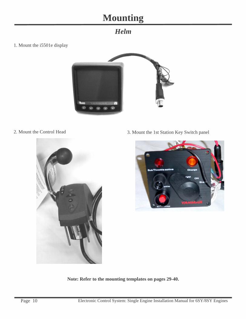
1. Mount the i5501e display
2. Mount the Control Head 3. Mount the 1st Station Key Switch panel
Mounting
Note: Refer to the mounting templates on pages 29-40.
Electronic Control System: Single Engine Installation Manual for 6SY/8SY Engines Page 11
ConnectivityEngine Room
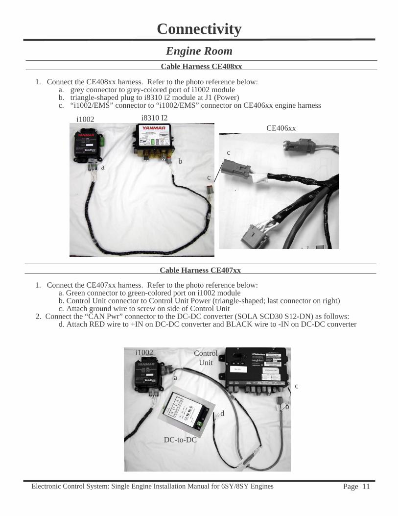
Cable Harness CE408xx
1. Connect the CE408xx harness. Refer to the photo reference below:a. grey connector to grey-colored port of i1002 module b. triangle-shaped plug to i8310 i2 module at J1 (Power)c. “i1002/EMS” connector to “i1002/EMS” connector on CE406xx engine harness
Cable Harness CE407xx
1. Connect the CE407xx harness. Refer to the photo reference below:a. Green connector to green-colored port on i1002 moduleb. Control Unit connector to Control Unit Power (triangle-shaped; last connector on right)c. Attach ground wire to screw on side of Control Unit
2. Connect the “CAN Pwr” connector to the DC-DC converter (SOLA SCD30 S12-DN) as follows:d. Attach RED wire to +IN on DC-DC converter and BLACK wire to -IN on DC-DC converter
b
i1002 i8310 I2
ab
c
CE406xx
c
i1002 Control Unit
DC-to-DC
ac
d
Electronic Control System: Single Engine Installation Manual for 6SY/8SY Engines Page 12
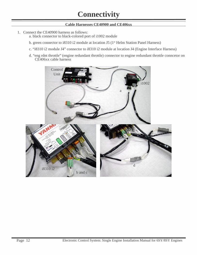
Cable Harnesses CE40900 and CE406xx
1. Connect the CE40900 harness as follows:a. black connector to black-colored port of i1002 module
b. green connector to i8310 i2 module at location J5 (1st Helm Station Panel Harness)
c. “i8310 i2 module J4” connector to i8310 i2 module at location J4 (Engine Interface Harness)
d. “eng rdnt throttle” (engine redundant throttle) connector to engine redundant throttle conncetor on CE406xx cable harness
a
b and c
d
Connectivity
Control Unit
i1002
i8310 i2

Electronic Control System: Single Engine Installation Manual for 6SY/8SY Engines Page 13
Cable Harness CE406xx and Jumper CE41200
1. Locate the engine EMS panel on the left side of engine facing the fl ywheel. The EMS panel has two terminal strips, each covered by a sheet metal cover plate. Loosen, but do not remove the four #15 torx-head screws that are holding down the left cover plate. Remove the cover plate.
2. From the 6-connector end of the CE406xx cable harness:
a. Connect the Engine EMS B-1 plug (10-pin, black) to the engine EMS terminal. Remove the protective cap and plug into the top left location (B1). Route the harnesses to exit the terminal strip, replace the cover plate and tighten the four corner screws.
b. Connect the ENG RDNT THROTTLE C108 plug (3-pin, gray) to the 3-pin gray EMS plug on the engine EMS panel.
c. Connect the TRANS OIL PRESS plug (3-pin, gray) to the transmission oil pressure sender, if used. This harness will not be used if the Trolling option is installed.
d. Locate the TRANS SWITCH plug (2-pin, gray). This is an optional neutral safety switch. Connect to transmis-sion neutral switch, if present. Otherwise, terminate with CE41200 “Jumper-Trans Switch.”
The following steps are performed at the engine.
e. Connect the COOLANT SENSOR plug (3-pin, gray) to the coolant level sensor on the engine.
6SY
8SY
Connectivity
CE41200
EMS Panel
a
e
d
c
b
To alternator harness(already connected)
Electronic Control System: Single Engine Installation Manual for 6SY/8SY Engines Page 14
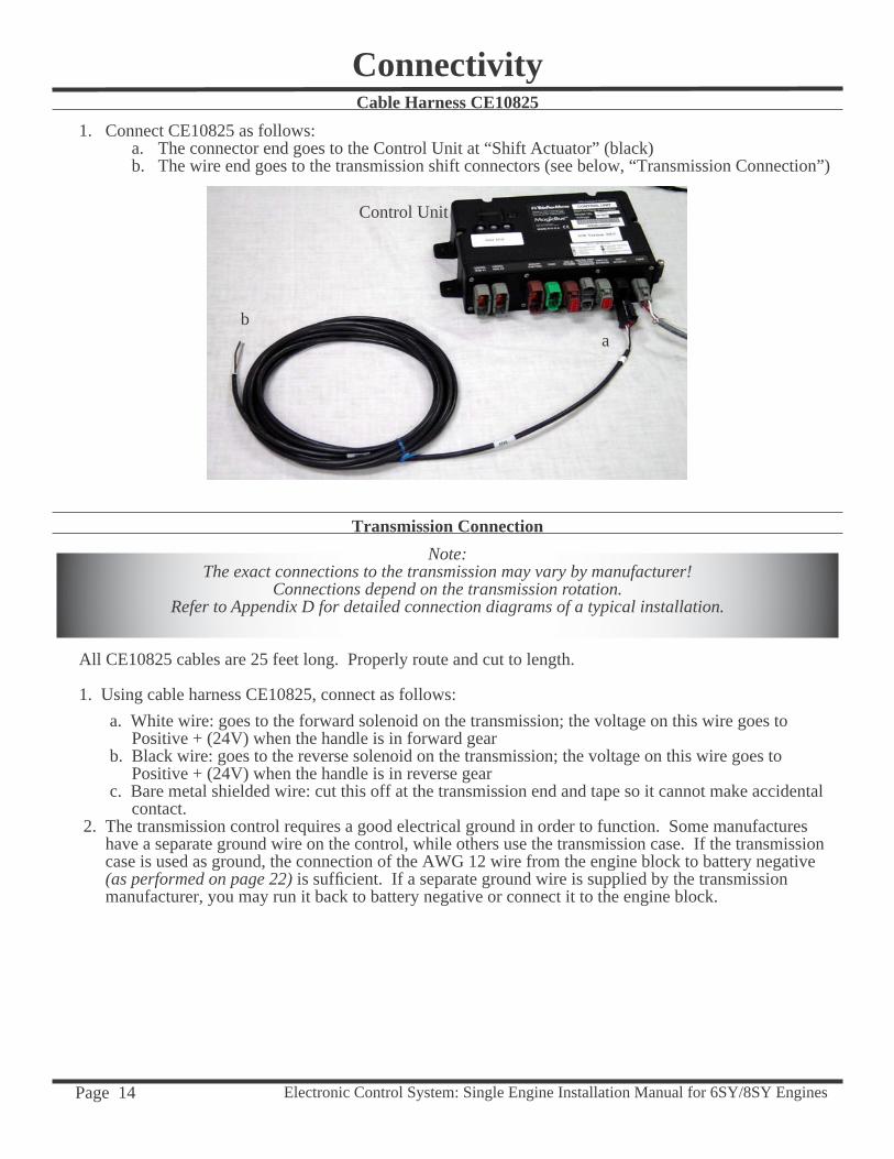
Cable Harness CE108251. Connect CE10825 as follows:
a. The connector end goes to the Control Unit at “Shift Actuator” (black)b. The wire end goes to the transmission shift connectors (see below, “Transmission Connection”)
Transmission Connection
Connectivity
ab
Control Unit
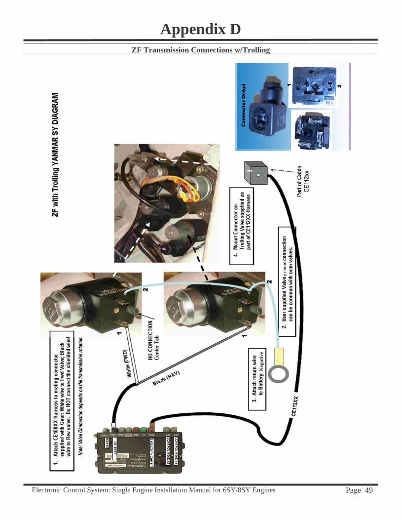
Note: The exact connections to the transmission may vary by manufacturer!
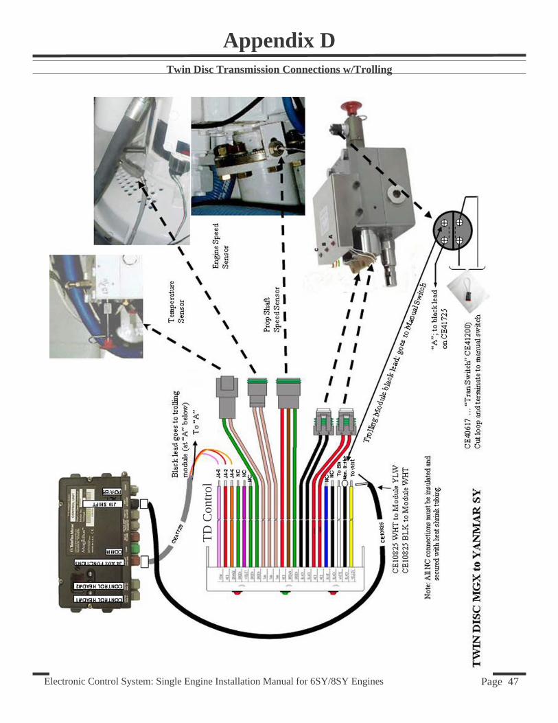
Connections depend on the transmission rotation. Refer to Appendix D for detailed connection diagrams of a typical installation.
All CE10825 cables are 25 feet long. Properly route and cut to length.
1. Using cable harness CE10825, connect as follows:
a. White wire: goes to the forward solenoid on the transmission; the voltage on this wire goes to Positive + (24V) when the handle is in forward gear
b. Black wire: goes to the reverse solenoid on the transmission; the voltage on this wire goes to Positive + (24V) when the handle is in reverse gear
c. Bare metal shielded wire: cut this off at the transmission end and tape so it cannot make accidental contact.
2. The transmission control requires a good electrical ground in order to function. Some manufactures have a separate ground wire on the control, while others use the transmission case. If the transmission case is used as ground, the connection of the AWG 12 wire from the engine block to battery negative (as performed on page 22) is suffi cient. If a separate ground wire is supplied by the transmission manufacturer, you may run it back to battery negative or connect it to the engine block.
Electronic Control System: Single Engine Installation Manual for 6SY/8SY Engines Page 15
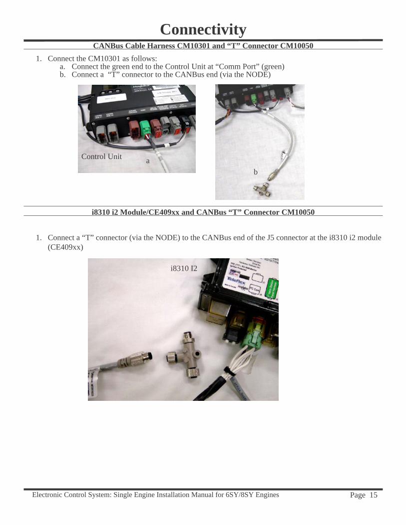
CANBus Cable Harness CM10301 and “T” Connector CM100501. Connect the CM10301 as follows:
a. Connect the green end to the Control Unit at “Comm Port” (green)b. Connect a “T” connector to the CANBus end (via the NODE)
i8310 i2 Module/CE409xx and CANBus “T” Connector CM10050
1. Connect a “T” connector (via the NODE) to the CANBus end of the J5 connector at the i8310 i2 module (CE409xx)
ab
Connectivity
Control Unit
i8310 I2
Electronic Control System: Single Engine Installation Manual for 6SY/8SY Engines Page 16
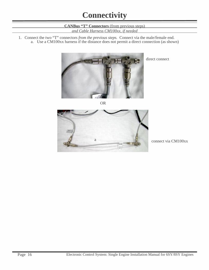
CANBus “T” Connectors (from previous steps) and Cable Harness CM100xx, if needed
1. Connect the two “T” connectors from the previous steps. Connect via the male/female end.a. Use a CM100xx harness if the distance does not permit a direct connection (as shown)
OR
Connectivity
a
direct connect
connect via CM100xx
Electronic Control System: Single Engine Installation Manual for 6SY/8SY Engines Page 17
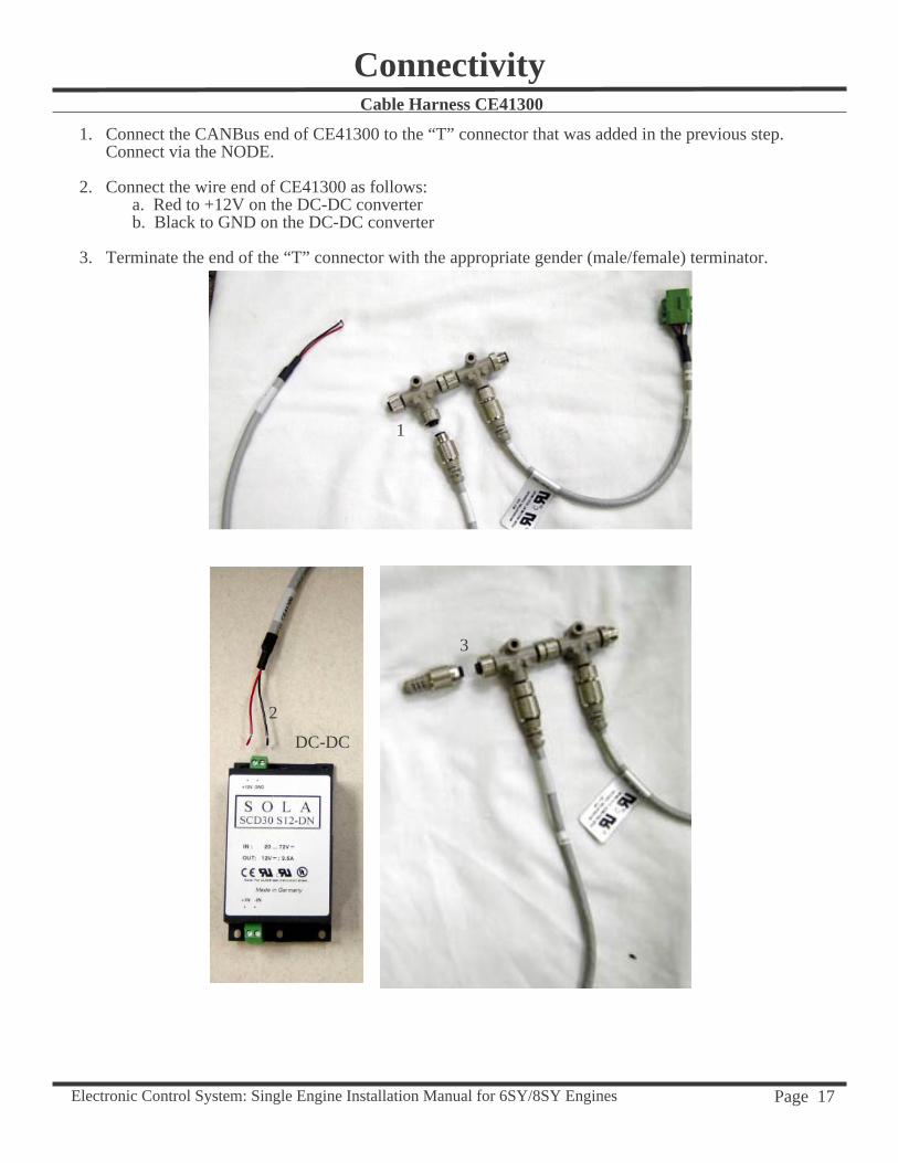
1. Connect the CANBus end of CE41300 to the “T” connector that was added in the previous step. Connect via the NODE.
2. Connect the wire end of CE41300 as follows:a. Red to +12V on the DC-DC converterb. Black to GND on the DC-DC converter
3. Terminate the end of the “T” connector with the appropriate gender (male/female) terminator.
Cable Harness CE41300
1
2
3
Connectivity
DC-DC
Electronic Control System: Single Engine Installation Manual for 6SY/8SY Engines Page 18
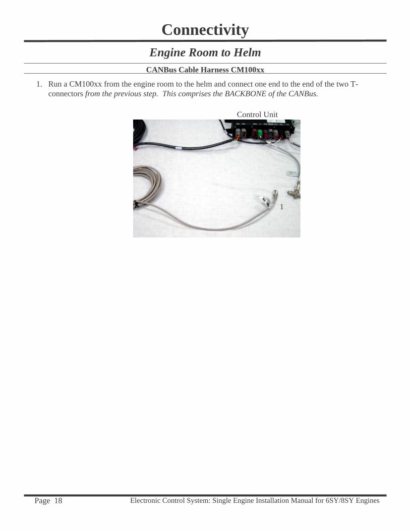
Engine Room to HelmCANBus Cable Harness CM100xx
1. Run a CM100xx from the engine room to the helm and connect one end to the end of the two T-connectors from the previous step. This comprises the BACKBONE of the CANBus.
1
Connectivity
Control Unit
Electronic Control System: Single Engine Installation Manual for 6SY/8SY Engines Page 19
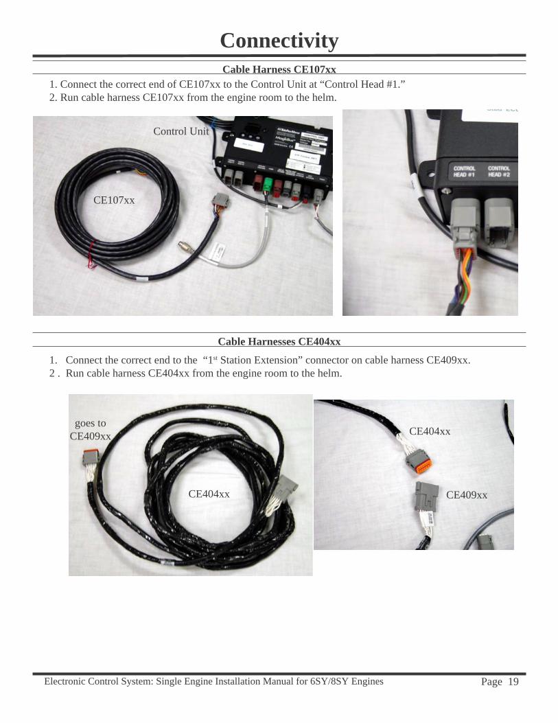
Cable Harness CE107xx 1. Connect the correct end of CE107xx to the Control Unit at “Control Head #1.”2. Run cable harness CE107xx from the engine room to the helm.
Cable Harnesses CE404xx
1. Connect the correct end to the “1st Station Extension” connector on cable harness CE409xx.2 . Run cable harness CE404xx from the engine room to the helm.
goes to CE409xx
Connectivity
CE107xx
CE404xx
CE409xxCE404xx
Control Unit
Electronic Control System: Single Engine Installation Manual for 6SY/8SY Engines Page 20
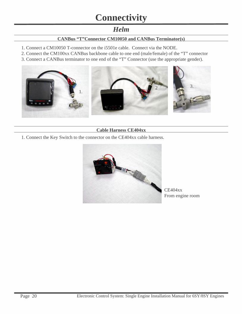
HelmCANBus “T”Connector CM10050 and CANBus Terminator(s)
1. Connect a CM10050 T-connector on the i5501e cable. Connect via the NODE.2. Connect the CM100xx CANBus backbone cable to one end (male/female) of the “T” connector 3. Connect a CANBus terminator to one end of the “T” Connector (use the appropriate gender).
Cable Harness CE404xx1. Connect the Key Switch to the connector on the CE404xx cable harness.
CE404xxFrom engine room
Connectivity
1.3.2
Electronic Control System: Single Engine Installation Manual for 6SY/8SY Engines Page 21
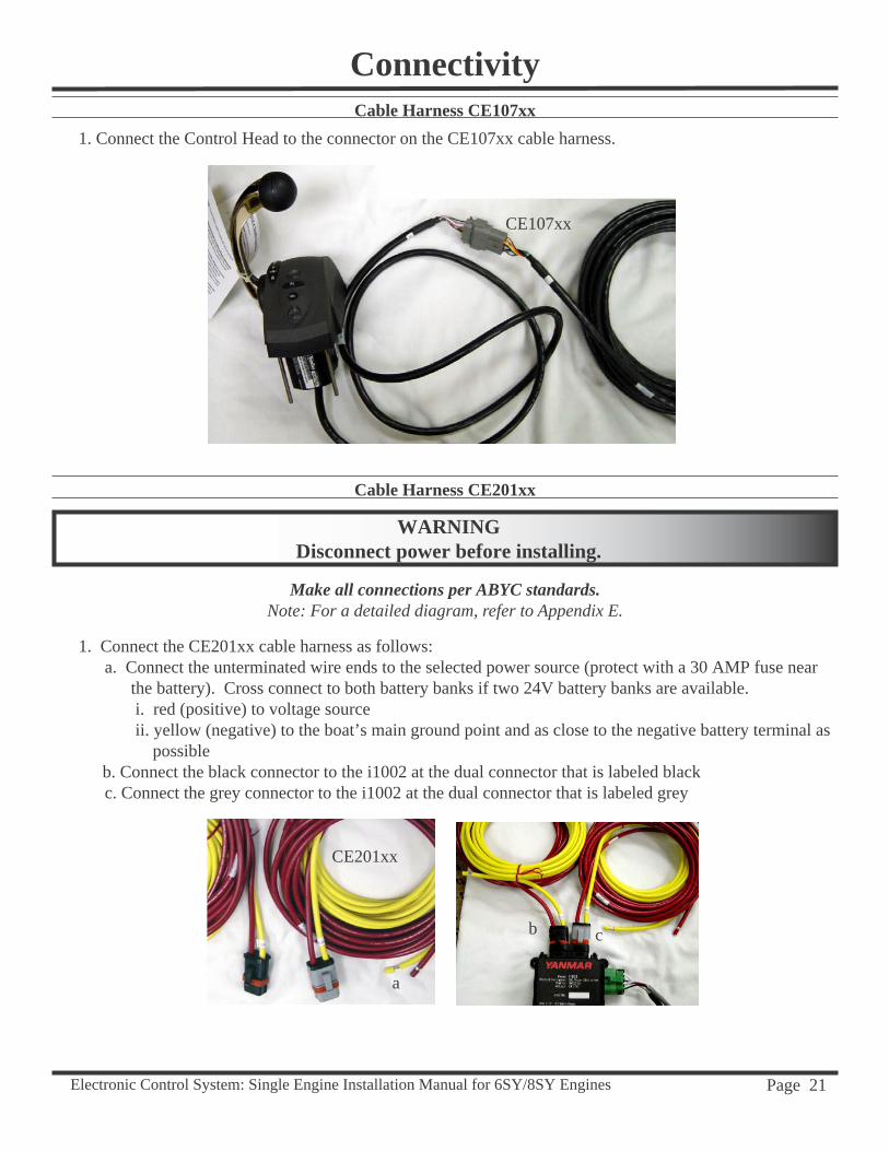
Cable Harness CE107xx1. Connect the Control Head to the connector on the CE107xx cable harness.
Connectivity
CE107xx
Cable Harness CE201xx
WARNINGDisconnect power before installing.
Make all connections per ABYC standards.Note: For a detailed diagram, refer to Appendix E.
1. Connect the CE201xx cable harness as follows:a. Connect the unterminated wire ends to the selected power source (protect with a 30 AMP fuse near
the battery). Cross connect to both battery banks if two 24V battery banks are available. i. red (positive) to voltage source ii. yellow (negative) to the boat’s main ground point and as close to the negative battery terminal as
possible b. Connect the black connector to the i1002 at the dual connector that is labeled blackc. Connect the grey connector to the i1002 at the dual connector that is labeled grey
CE201xx
cb
a
Electronic Control System: Single Engine Installation Manual for 6SY/8SY Engines Page 22
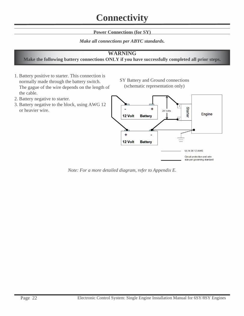
Power Connections (for SY)
Make all connections per ABYC standards.
WARNINGMake the following battery connections ONLY if you have successfully completed all prior steps.
Connectivity
1. Battery positive to starter. This connection is normally made through the battery switch. The gague of the wire depends on the length of the cable.2. Battery negative to starter. 3. Battery negative to the block, using AWG 12 or heavier wire.
SY Battery and Ground connections(schematic representation only)
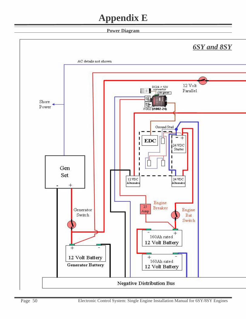
Note: For a more detailed diagram, refer to Appendix E.
Electronic Control System: Single Engine Installation Manual for 6SY/8SY Engines Page 23
Pre-Start Up ChecklistConnection Checks1. Ensure all connectors are plugged in and properly seated.2. Verify that the digital displays, engine interface, and the control unit are connected to the NMEA 2000®
network.3. Make sure the CANbus “T” Connectors are not tied down too tightly, thus causing stress.4. Check each end of the NMEA 2000® CANbus to ensure that a terminator has been properly installed.5. Verify that the engine ignition panel is properly connected at the helm station. 6. Ensure the engine block is connected to the negative side (-) of the battery by the wire shown on page 22.
24 Volts DC Check1. Remove the grey and black plugs from each i1002 module.2. Turn the battery switches and the engine breaker on.3. Test for 24 Volts DC on each of these connectors. 4. When confi rmed, turn off the engine battery switches and the engine breakers and reconnect the grey and black
plugs. 5. Turn the engine battery switches and the engine breakers back on.
Key Switch Check1. Turn the key switch to the “on” position, but do not start the engine. You should hear the injectors “click..”
Module Light/Data Checks1. The i5501e display(s) comes on. 2. The i8310 i2 Engine Interface status indicators should show two blinking LEDs.3. The Control lever should be in the neutral position;
i5501e Display Check1. Press the left-most key on the digital display. The data should be available.2. Turn off the engine breaker.
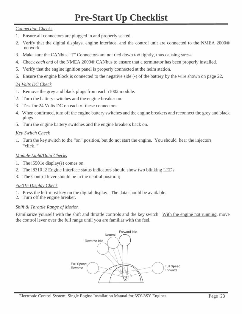
Shift & Throttle Range of MotionFamiliarize yourself with the shift and throttle controls and the key switch. With the engine not running, move the control lever over the full range until you are familiar with the feel.
Electronic Control System: Single Engine Installation Manual for 6SY/8SY Engines Page 24
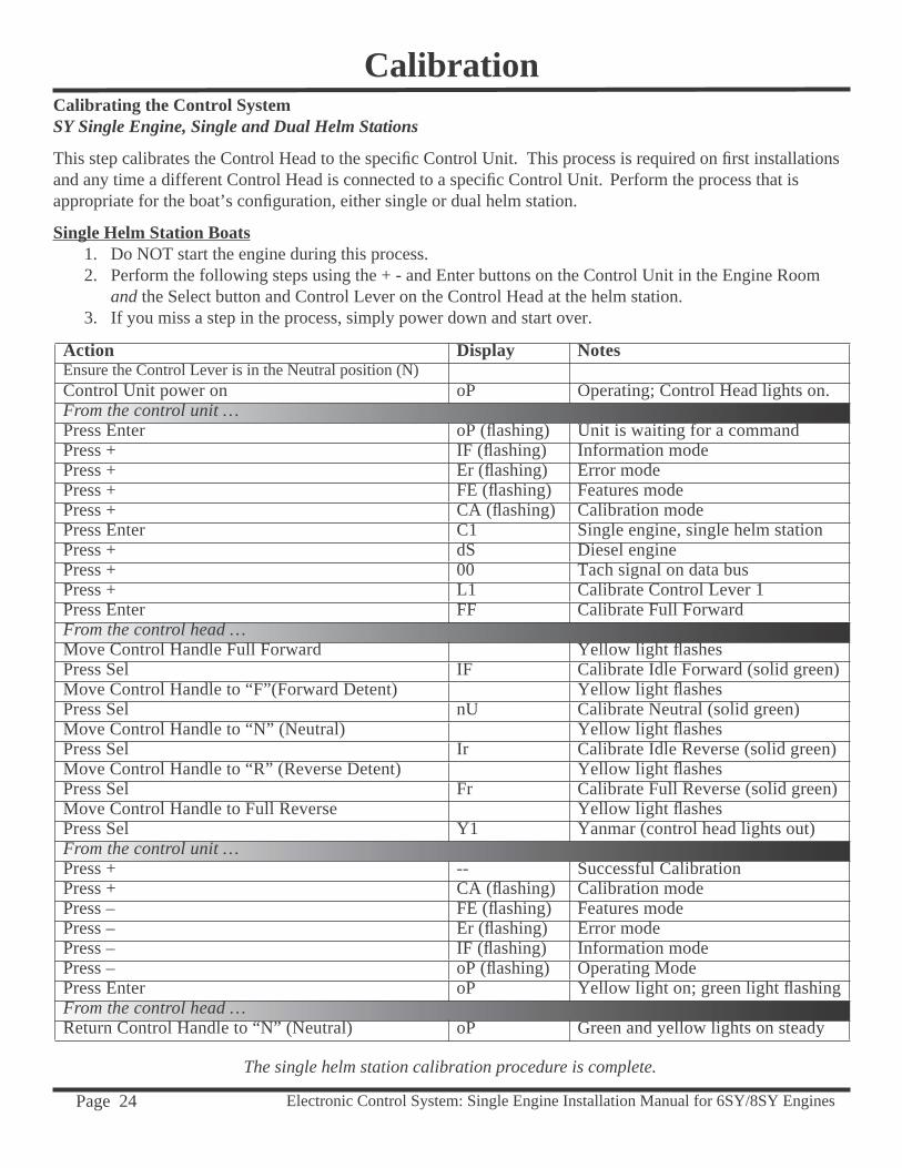
Calibration
Action Display NotesEnsure the Control Lever is in the Neutral position (N)Control Unit power on oP Operating; Control Head lights on.From the control unit …Press Enter oP (fl ashing) Unit is waiting for a commandPress + IF (fl ashing) Information modePress + Er (fl ashing) Error modePress + FE (fl ashing) Features modePress + CA (fl ashing) Calibration modePress Enter C1 Single engine, single helm stationPress + dS Diesel enginePress + 00 Tach signal on data busPress + L1 Calibrate Control Lever 1Press Enter FF Calibrate Full ForwardFrom the control head …Move Control Handle Full Forward Yellow light fl ashes Press Sel IF Calibrate Idle Forward (solid green)Move Control Handle to “F”(Forward Detent) Yellow light fl ashesPress Sel nU Calibrate Neutral (solid green)Move Control Handle to “N” (Neutral) Yellow light fl ashesPress Sel Ir Calibrate Idle Reverse (solid green)Move Control Handle to “R” (Reverse Detent) Yellow light fl ashesPress Sel Fr Calibrate Full Reverse (solid green)Move Control Handle to Full Reverse Yellow light fl ashesPress Sel Y1 Yanmar (control head lights out)From the control unit …Press + -- Successful CalibrationPress + CA (fl ashing) Calibration modePress – FE (fl ashing) Features modePress – Er (fl ashing) Error modePress – IF (fl ashing) Information modePress – oP (fl ashing) Operating ModePress Enter oP Yellow light on; green light fl ashingFrom the control head …Return Control Handle to “N” (Neutral) oP Green and yellow lights on steady
Calibrating the Control SystemSY Single Engine, Single and Dual Helm Stations
This step calibrates the Control Head to the specifi c Control Unit. This process is required on fi rst installations and any time a different Control Head is connected to a specifi c Control Unit. Perform the process that is appropriate for the boat’s confi guration, either single or dual helm station.
Single Helm Station Boats1. Do NOT start the engine during this process.2. Perform the following steps using the + - and Enter buttons on the Control Unit in the Engine Room
and the Select button and Control Lever on the Control Head at the helm station.3. If you miss a step in the process, simply power down and start over.
The single helm station calibration procedure is complete.
Electronic Control System: Single Engine Installation Manual for 6SY/8SY Engines Page 25
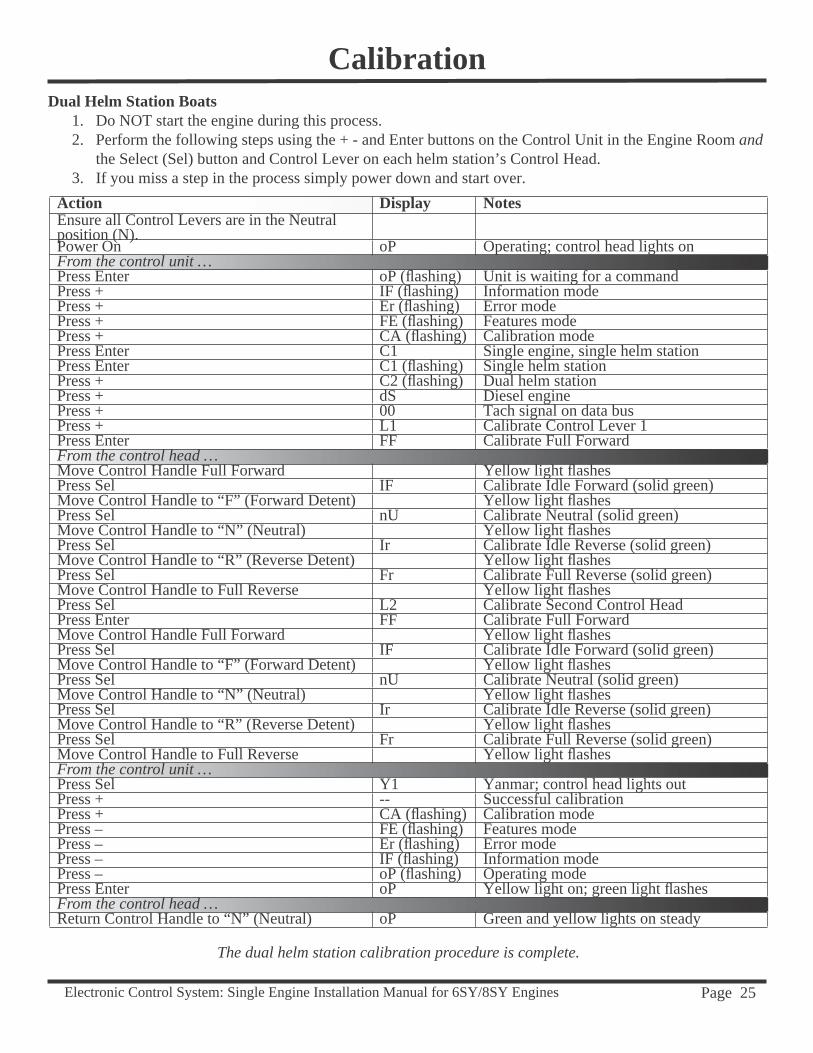
CalibrationDual Helm Station Boats
1. Do NOT start the engine during this process.2. Perform the following steps using the + - and Enter buttons on the Control Unit in the Engine Room and
the Select (Sel) button and Control Lever on each helm station’s Control Head. 3. If you miss a step in the process simply power down and start over.
Action Display NotesEnsure all Control Levers are in the Neutral position (N).Power On oP Operating; control head lights onFrom the control unit …Press Enter oP (fl ashing) Unit is waiting for a commandPress + IF (fl ashing) Information modePress + Er (fl ashing) Error modePress + FE (fl ashing) Features modePress + CA (fl ashing) Calibration modePress Enter C1 Single engine, single helm stationPress Enter C1 (fl ashing) Single helm stationPress + C2 (fl ashing) Dual helm stationPress + dS Diesel enginePress + 00 Tach signal on data busPress + L1 Calibrate Control Lever 1Press Enter FF Calibrate Full ForwardFrom the control head …Move Control Handle Full Forward Yellow light fl ashes Press Sel IF Calibrate Idle Forward (solid green)Move Control Handle to “F” (Forward Detent) Yellow light fl ashesPress Sel nU Calibrate Neutral (solid green)Move Control Handle to “N” (Neutral) Yellow light fl ashesPress Sel Ir Calibrate Idle Reverse (solid green)Move Control Handle to “R” (Reverse Detent) Yellow light fl ashesPress Sel Fr Calibrate Full Reverse (solid green)Move Control Handle to Full Reverse Yellow light fl ashesPress Sel L2 Calibrate Second Control HeadPress Enter FF Calibrate Full ForwardMove Control Handle Full Forward Yellow light fl ashes Press Sel IF Calibrate Idle Forward (solid green)Move Control Handle to “F” (Forward Detent) Yellow light fl ashesPress Sel nU Calibrate Neutral (solid green)Move Control Handle to “N” (Neutral) Yellow light fl ashesPress Sel Ir Calibrate Idle Reverse (solid green)Move Control Handle to “R” (Reverse Detent) Yellow light fl ashesPress Sel Fr Calibrate Full Reverse (solid green)Move Control Handle to Full Reverse Yellow light fl ashesFrom the control unit …Press Sel Y1 Yanmar; control head lights outPress + -- Successful calibrationPress + CA (fl ashing) Calibration modePress – FE (fl ashing) Features modePress – Er (fl ashing) Error modePress – IF (fl ashing) Information modePress – oP (fl ashing) Operating modePress Enter oP Yellow light on; green light fl ashesFrom the control head …Return Control Handle to “N” (Neutral) oP Green and yellow lights on steady
The dual helm station calibration procedure is complete.
Electronic Control System: Single Engine Installation Manual for 6SY/8SY Engines Page 26
Ignition Switch PanelTurn on the battery switche(s) and the engine control breaker(s). Familiarize yourself with the ignition switch panel. The panel switche may be a conventional key type switch, or it may be "rocker" type switches. On either type there are three positions: OFF – ON – START. Next to it will be an EMERGENCY STOP switch. On this system, turning the key to off, or moving the Rocker switch to the off position WILL result in the engine shutting down. Note that on electronic engines, shut-down occurs after a delay of a few seconds.
WARNINGThe EMERGENCY STOP switch is not to be used for normal engine shutdown. The emergency stop
switch disconnects the power from the entire system and may make the engine hard to re-start. Use the normal key or rocker switch to turn the engine "OFF."
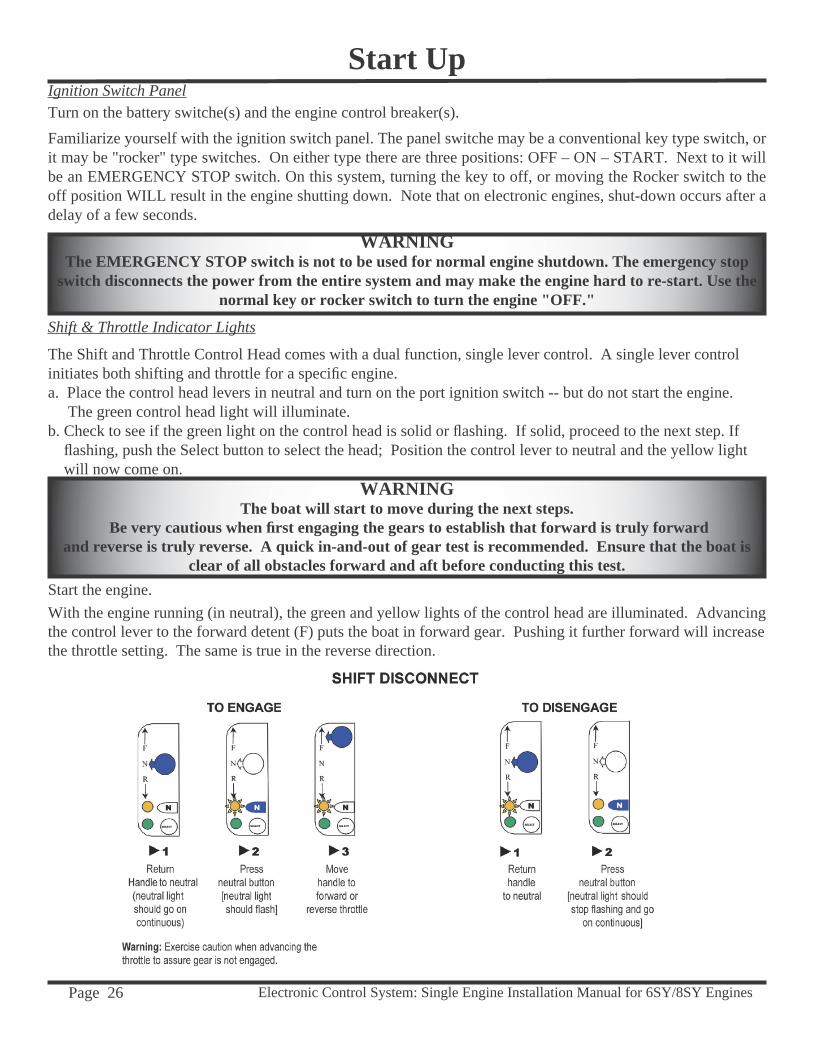
Shift & Throttle Indicator Lights
The Shift and Throttle Control Head comes with a dual function, single lever control. A single lever control initiates both shifting and throttle for a specifi c engine.a. Place the control head levers in neutral and turn on the port ignition switch -- but do not start the engine. The green control head light will illuminate. b. Check to see if the green light on the control head is solid or fl ashing. If solid, proceed to the next step. If fl ashing, push the Select button to select the head; Position the control lever to neutral and the yellow light will now come on.
Start Up
WARNINGThe boat will start to move during the next steps.
Be very cautious when fi rst engaging the gears to establish that forward is truly forwardand reverse is truly reverse. A quick in-and-out of gear test is recommended. Ensure that the boat is
clear of all obstacles forward and aft before conducting this test.Start the engine.With the engine running (in neutral), the green and yellow lights of the control head are illuminated. Advancing the control lever to the forward detent (F) puts the boat in forward gear. Pushing it further forward will increase the throttle setting. The same is true in the reverse direction.
Electronic Control System: Single Engine Installation Manual for 6SY/8SY Engines Page 27
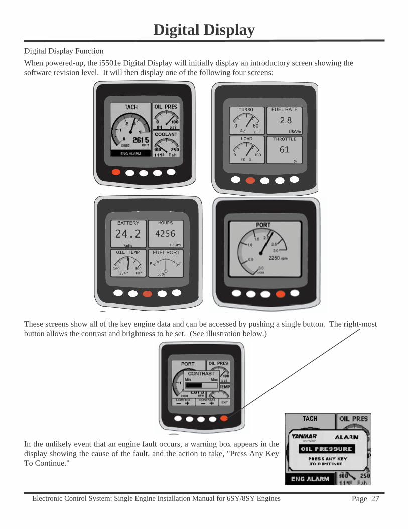
In the unlikely event that an engine fault occurs, a warning box appears in the display showing the cause of the fault, and the action to take, "Press Any Key To Continue."
Digital DisplayDigital Display FunctionWhen powered-up, the i5501e Digital Display will initially display an introductory screen showing thesoftware revision level. It will then display one of the following four screens:
These screens show all of the key engine data and can be accessed by pushing a single button. The right-most button allows the contrast and brightness to be set. (See illustration below.)
Electronic Control System: Single Engine Installation Manual for 6SY/8SY Engines Page 28
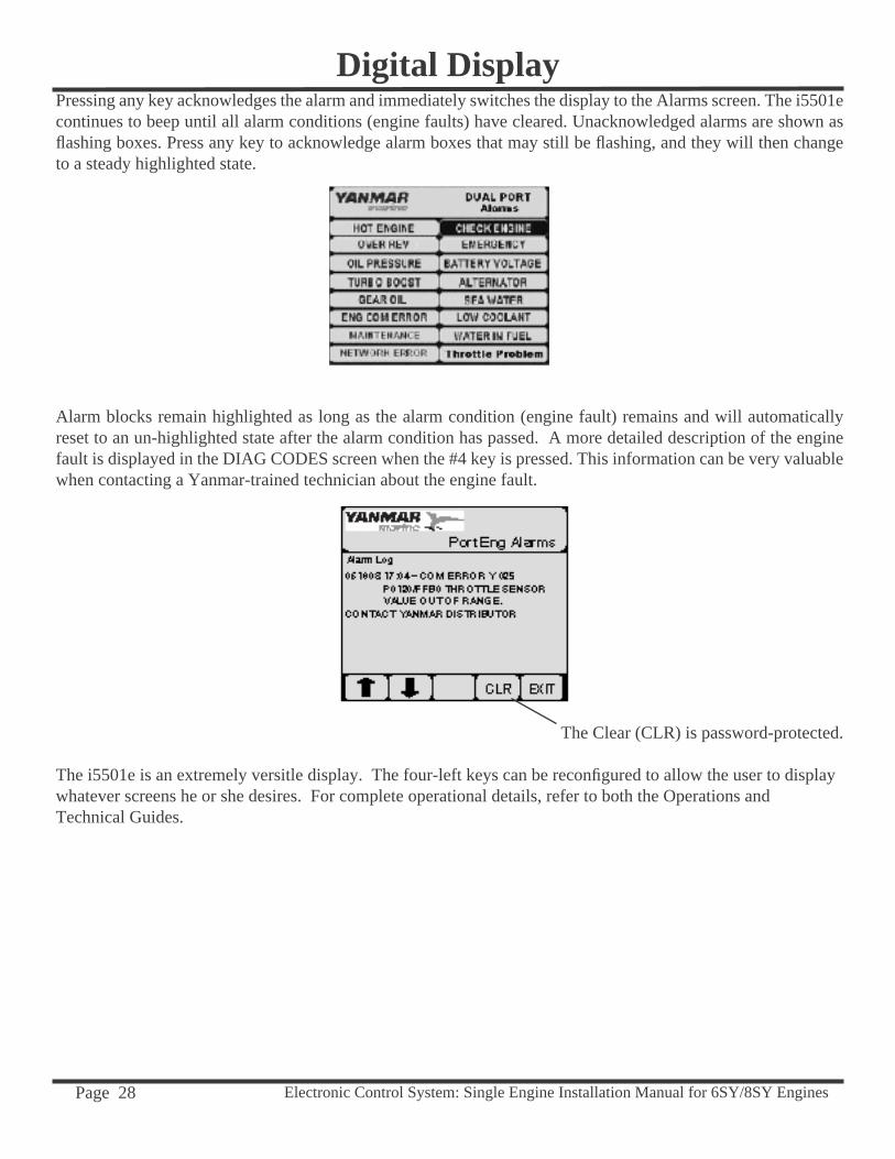
Pressing any key acknowledges the alarm and immediately switches the display to the Alarms screen. The i5501e continues to beep until all alarm conditions (engine faults) have cleared. Unacknowledged alarms are shown as fl ashing boxes. Press any key to acknowledge alarm boxes that may still be fl ashing, and they will then change to a steady highlighted state.
Alarm blocks remain highlighted as long as the alarm condition (engine fault) remains and will automatically reset to an un-highlighted state after the alarm condition has passed. A more detailed description of the engine fault is displayed in the DIAG CODES screen when the #4 key is pressed. This information can be very valuable when contacting a Yanmar-trained technician about the engine fault.
The Clear (CLR) is password-protected.
The i5501e is an extremely versitle display. The four-left keys can be reconfi gured to allow the user to display whatever screens he or she desires. For complete operational details, refer to both the Operations and Technical Guides.
Digital Display
Electronic Control System: Single Engine Installation Manual for 6SY/8SY Engines Page 29
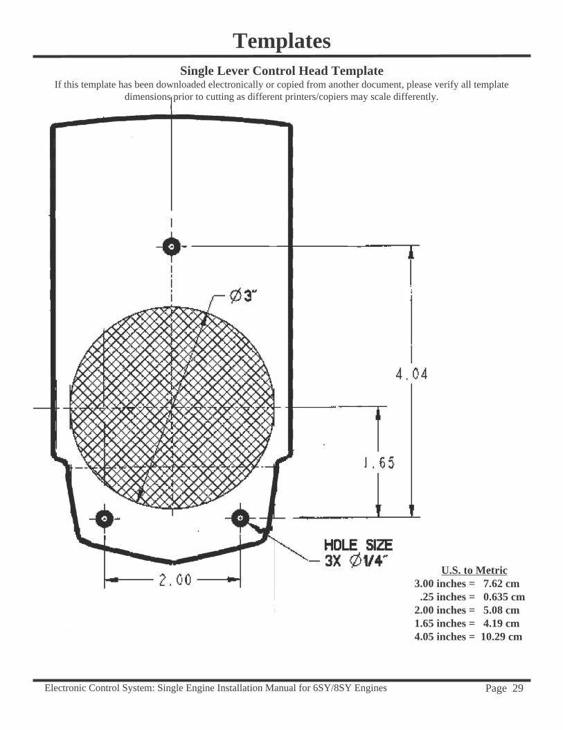
TemplatesSingle Lever Control Head Template
If this template has been downloaded electronically or copied from another document, please verify all template dimensions prior to cutting as different printers/copiers may scale differently.
U.S. to Metric 3.00 inches = 7.62 cm .25 inches = 0.635 cm2.00 inches = 5.08 cm1.65 inches = 4.19 cm4.05 inches = 10.29 cm

Electronic Control System: Single Engine Installation Manual for 6SY/8SY Engines Page 30
Templates
This page has been left blank.
Electronic Control System: Single Engine Installation Manual for 6SY/8SY Engines Page 31
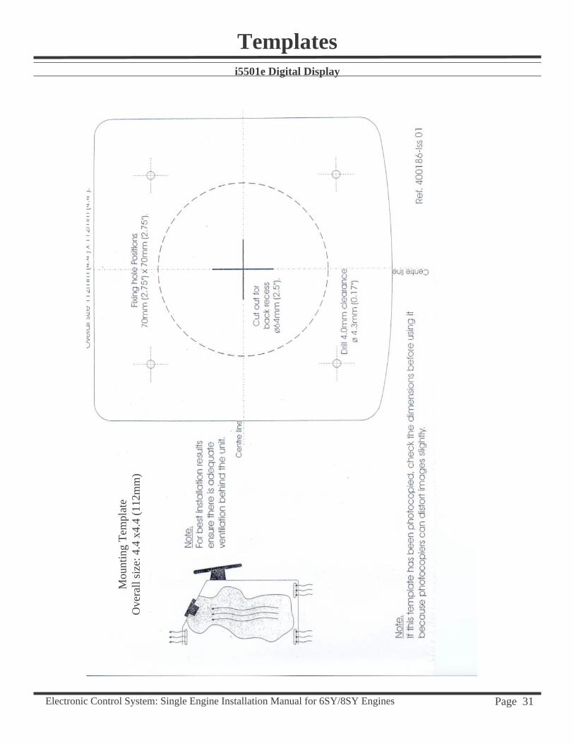
Templatesi5501e Digital Display
Mou
ntin
g Te
mpl
ate
Ove
rall
size
: 4.4
x4.
4 (1
12m
m)

Electronic Control System: Single Engine Installation Manual for 6SY/8SY Engines Page 32
TemplatesThis page has been left blank.

Electronic Control System: Single Engine Installation Manual for 6SY/8SY Engines Page 33
Templates
If this template has been downloaded electronically or copied from another document, please verify all template dimensions prior to cutting as different printers/copiers may scale differently.
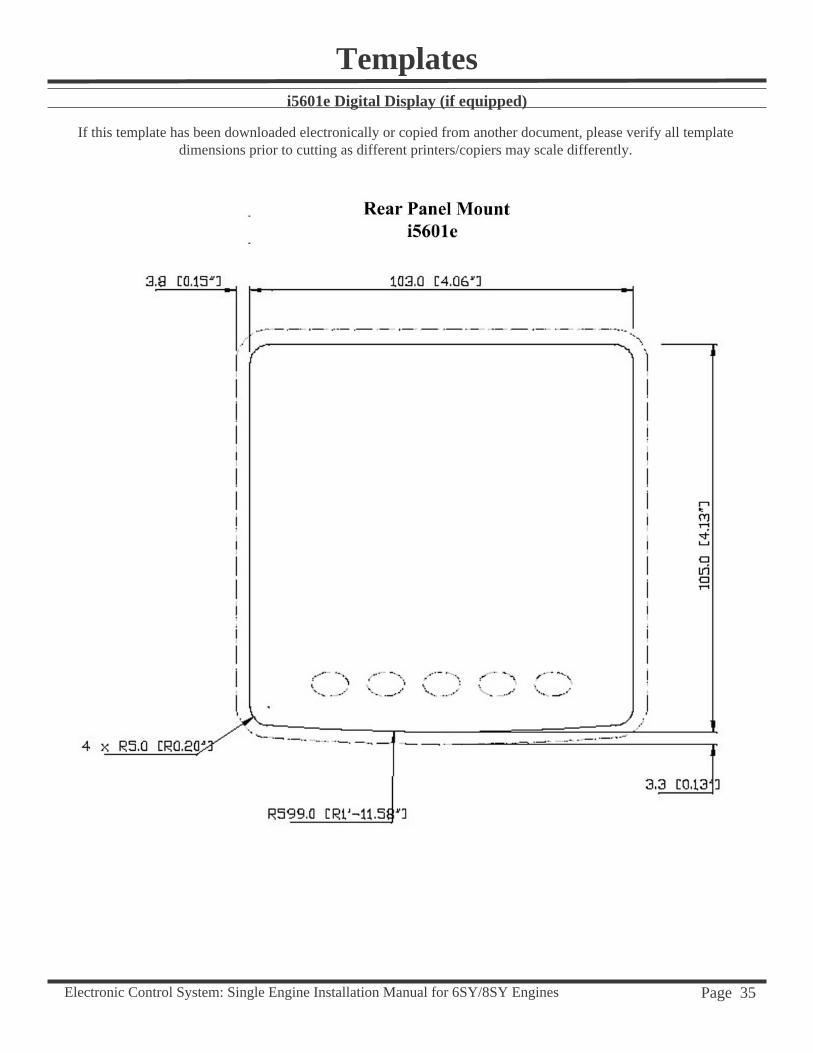
i5601e Digital Display (if equipped)

Electronic Control System: Single Engine Installation Manual for 6SY/8SY Engines Page 34
TemplatesThis page has been left blank.
Electronic Control System: Single Engine Installation Manual for 6SY/8SY Engines Page 35
Templatesi5601e Digital Display (if equipped)
If this template has been downloaded electronically or copied from another document, please verify all template dimensions prior to cutting as different printers/copiers may scale differently.

Electronic Control System: Single Engine Installation Manual for 6SY/8SY Engines Page 36
Electronic Control System: Single Engine Installation Manual for 6SY/8SY Engines Page 37
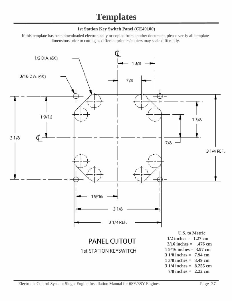
Templates1st Station Key Switch Panel (CE40100)
If this template has been downloaded electronically or copied from another document, please verify all template dimensions prior to cutting as different printers/copiers may scale differently.
U.S. to Metric 1/2 inches = 1.27 cm 3/16 inches = .476 cm1 9/16 inches = 3.97 cm3 1/8 inches = 7.94 cm1 3/8 inches = 3.49 cm3 1/4 inches = 8.255 cm 7/8 inches = 2.22 cm

Electronic Control System: Single Engine Installation Manual for 6SY/8SY Engines Page 38
This page has been left blank.
Templates
Electronic Control System: Single Engine Installation Manual for 6SY/8SY Engines Page 39
5If this template has been downloaded electronically or copied from another document, please verify all template
dimensions prior to cutting as different printers/copiers may scale differently.
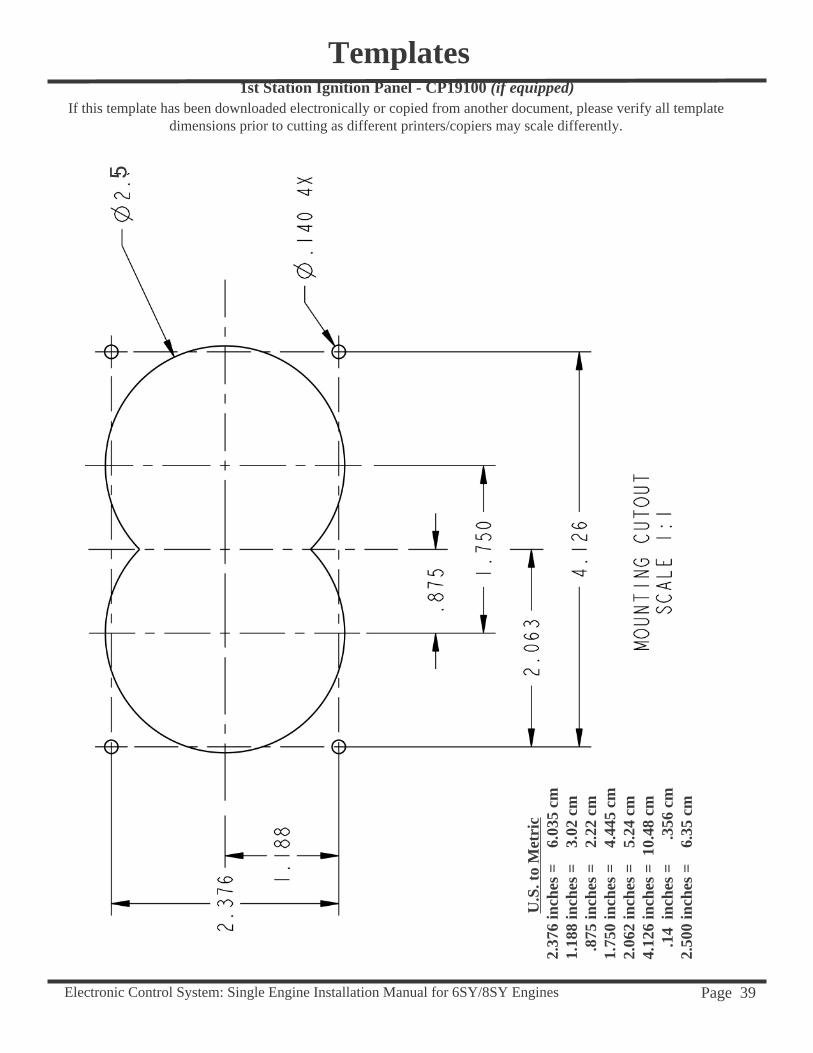
Templates1st Station Ignition Panel - CP19100 (if equipped)
U.S
. to
Met
ric
2.37
6 in
ches
=
6.0
35 c
m1.
188
inch
es =
3
.02
cm .
875
inch
es =
2
.22
cm1.
750
inch
es =
4
.445
cm
2.06
2 in
ches
=
5.2
4 cm
4.12
6 in
ches
= 1
0.48
cm
.1
4 in
ches
=
.3
56 c
m2.
500
inch
es =
6
.35
cm

Electronic Control System: Single Engine Installation Manual for 6SY/8SY Engines Page 40
This page has been left blank.
Templates
Electronic Control System: Single Engine Installation Manual for 6SY/8SY Engines Page 41
Appendix A
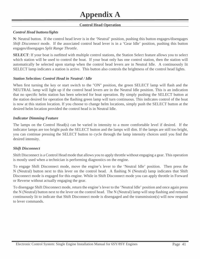
Control Head buttons/lights
N: Neutral button. If the control head lever is in the ‘Neutral’ position, pushing this button engages/disengages Shift Disconnect mode. If the associated control head lever is in a ‘Gear Idle’ position, pushing this button engages/disengages Split Range Throttle.
SELECT: If your boat is outfi tted with multiple control stations, the Station Select feature allows you to select which station will be used to control the boat. If your boat only has one control station, then the station will automatically be selected upon startup when the control head levers are in Neutral Idle. A continuously lit SELECT lamp indicates a station is active. This button also controls the brightness of the control head lights.
Station Selection: Control Head in Neutral / Idle
When fi rst turning the key or start switch to the "ON" position, the green SELECT lamp will fl ash and the NEUTRAL lamp will light up if the control head levers are in the Neutral Idle position. This is an indication that no specifi c helm station has been selected for boat operation. By simply pushing the SELECT button at the station desired for operation the fl ashing green lamp will turn continuous. This indicates control of the boat is now at this station location. If you choose to change helm locations, simply push the SELECT button at the desired helm location provided the control head is in Neutral Idle.
Indicator Dimming Feature
The lamps on the Control Head(s) can be varied in intensity to a more comfortable level if desired. If the indicator lamps are too bright push the SELECT button and the lamps will dim. If the lamps are still too bright, you can continue pressing the SELECT button to cycle through the lamp intensity choices until you fi nd the desired intensity.
Shift Disconnect
Shift Disconnect is a Control Head mode that allows you to apply throttle without engaging a gear. This operation is mostly used when a technician is performing diagnostics on the engine.
To engage Shift Disconnect mode, move the engine’s lever to the ‘Neutral Idle’ position. Then press the N (Neutral) button next to this lever on the control head. A fl ashing N (Neutral) lamp indicates that Shift Disconnect mode is engaged for this engine. While in Shift Disconnect mode you can apply throttle in Forward or Reverse without actually engaging the gear.
To disengage Shift Disconnect mode, return the engine’s lever to the ‘Neutral Idle’ position and once again press the N (Neutral) button next to the lever on the control head. The N (Neutral) lamp will stop fl ashing and remains continuously lit to indicate that Shift Disconnect mode is disengaged and the transmission(s) will now respond to lever commands.
Control Head Operation

Electronic Control System: Single Engine Installation Manual for 6SY/8SY Engines Page 42
Split Range Throttle
This Control Head mode gives you greater throttle sensitivity. In Split Range Throttle (SRT), moving an engine’s control lever all the way to the ‘Full Forward’ position will only produce the maximum percentage of wide open throttle selected in the "Features Selection" of the Control Unit program options. Typical Throttle Limit percentages for SRT are 5% to 50%, with 25% being the default value. When SRT is engaged, your engines temporarily use a linear throttle response for application of the chosen SRT Throttle Limit. The throttle curves previously selected are automatically restored upon disengaging SRT.
To engage Split Range Throttle, move the engine’s lever to an in-gear Idle position (Forward Idle or Reverse Idle) and press the N (Neutral) button next to this lever on the control head. The N (Neutral) lamp will fl ash to indicate that Split Range Throttle is engaged.
While in Split Range Throttle, the system will shift normally but the throttle will be limited in both gears (Forward and Reverse) to the Throttle Limit percentage programmed for WOT (Wide Open Throttle) in the "Features Selection" of the Control Unit program options.
If the system is shifted into Neutral while in Split Range Throttle engine mode, the N (Neutral) lamp will come on (steady) to indicate that the system is in Neutral. Note that this action will NOT exit Split Range Throttle mode. When the lever is moved back into gear, the N (Neutral) lamp will resume fl ashing to indicate that the system is still in Split Range Throttle.
To disengage Split Range Throttle, return the engine’s lever to a Gear Idle position (Forward Idle or Reverse Idle) and again press the N (Neutral) button next to the lever on the control head. The N (Neutral) lamp will stop fl ashing, indicating that Split Range Throttle has been disengaged.
Appendix AControl Head Operation
Electronic Control System: Single Engine Installation Manual for 6SY/8SY Engines Page 43
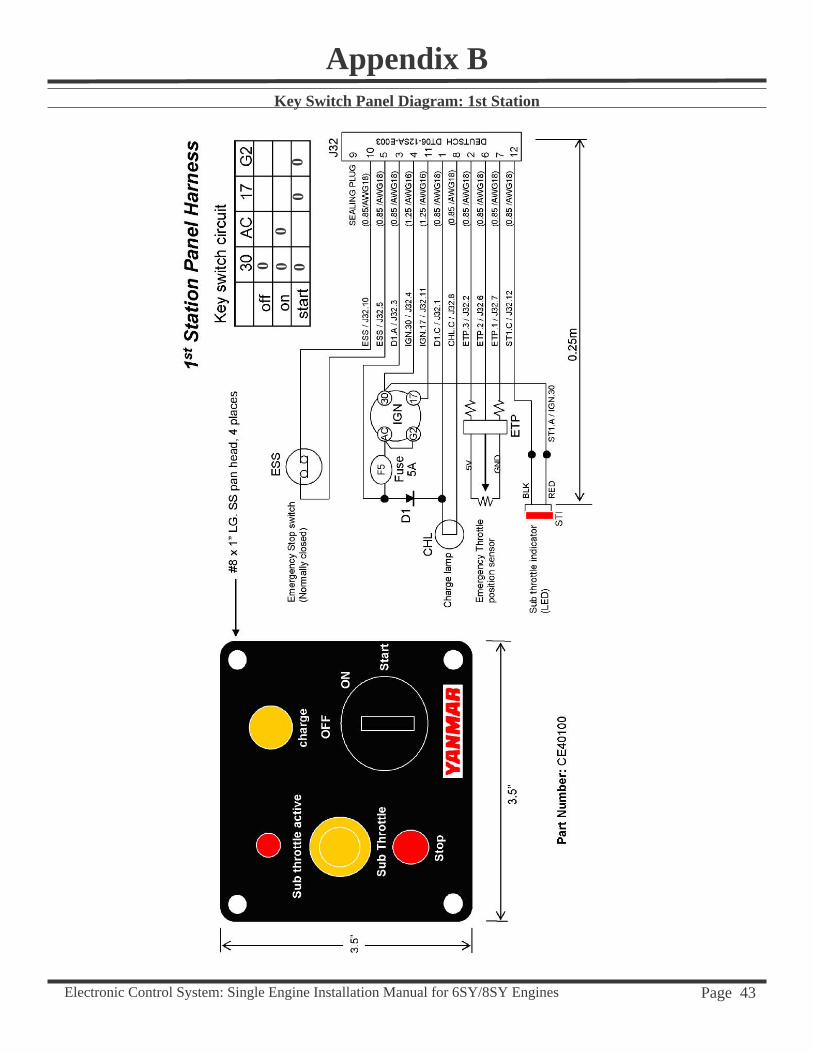
Key Switch Panel Diagram: 1st Station
Appendix B
0 000
00
Electronic Control System: Single Engine Installation Manual for 6SY/8SY Engines Page 44
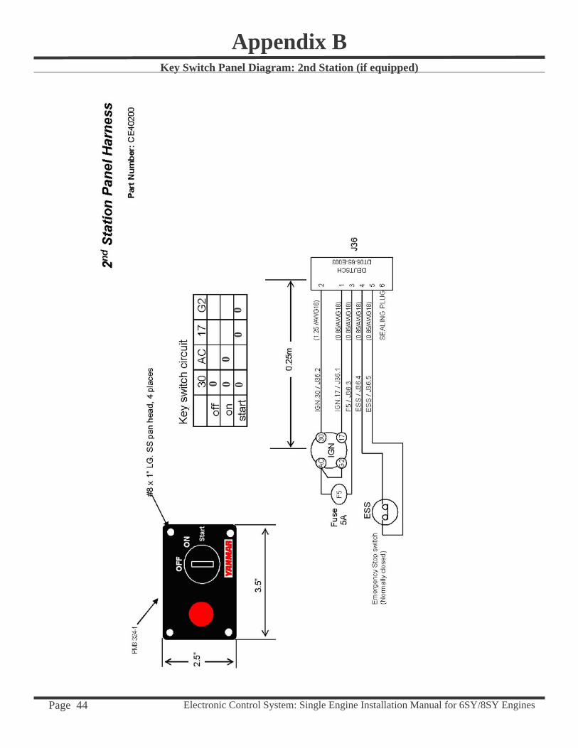
Key Switch Panel Diagram: 2nd Station (if equipped)
Appendix B
0 000
00
Electronic Control System: Single Engine Installation Manual for 6SY/8SY Engines Page 45
Appendix CYanmar SY Default Settings: Single Engine
As of January 1, 2005 Yanmar SY i6000 Control Units are shipped with the following defaults: Single Engine - CUKSEFeatures Calibration25 Split Range Throttle 25% C1 Single Engine Single StationF8 F8 Forward Throttle Curve dS DieselR1 R1 Reverse Throttle Curve 00 RPM from data bus96 9.6 Programmable Shift Delay L1 Lever Calibration02 0.2 second Fixed Shift Delay YI YanmaroF Station Select Protection OffnI Neutral, Idle Fail Safe Response
Electronic Control System: Single Engine Installation Manual for 6SY/8SY Engines Page 46
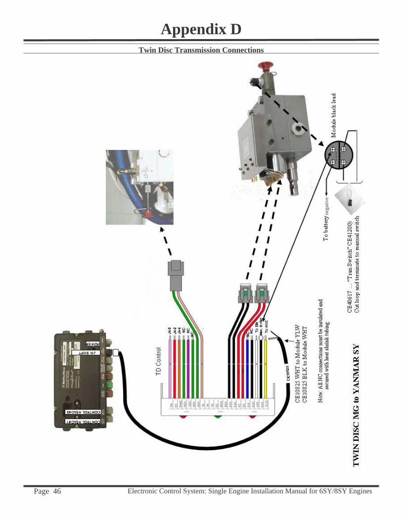
Twin Disc Transmission Connections
Appendix D
nega
tive
Electronic Control System: Single Engine Installation Manual for 6SY/8SY Engines Page 47
TD C
ontro
l
Appendix DTwin Disc Transmission Connections w/Trolling

Electronic Control System: Single Engine Installation Manual for 6SY/8SY Engines Page 48
Appendix DZF Transmission Connections
Neg
ativ
e
grou
nd
Electronic Control System: Single Engine Installation Manual for 6SY/8SY Engines Page 49
Appendix DZF Transmission Connections w/Trolling
grou
nd
Neg
ativ
e
Electronic Control System: Single Engine Installation Manual for 6SY/8SY Engines Page 50
Power Diagram
Appendix E
6SY and 8SY
Electronic Control System: Single Engine Installation Manual for 6SY/8SY Engines Page 51
Power Diagram
Appendix E
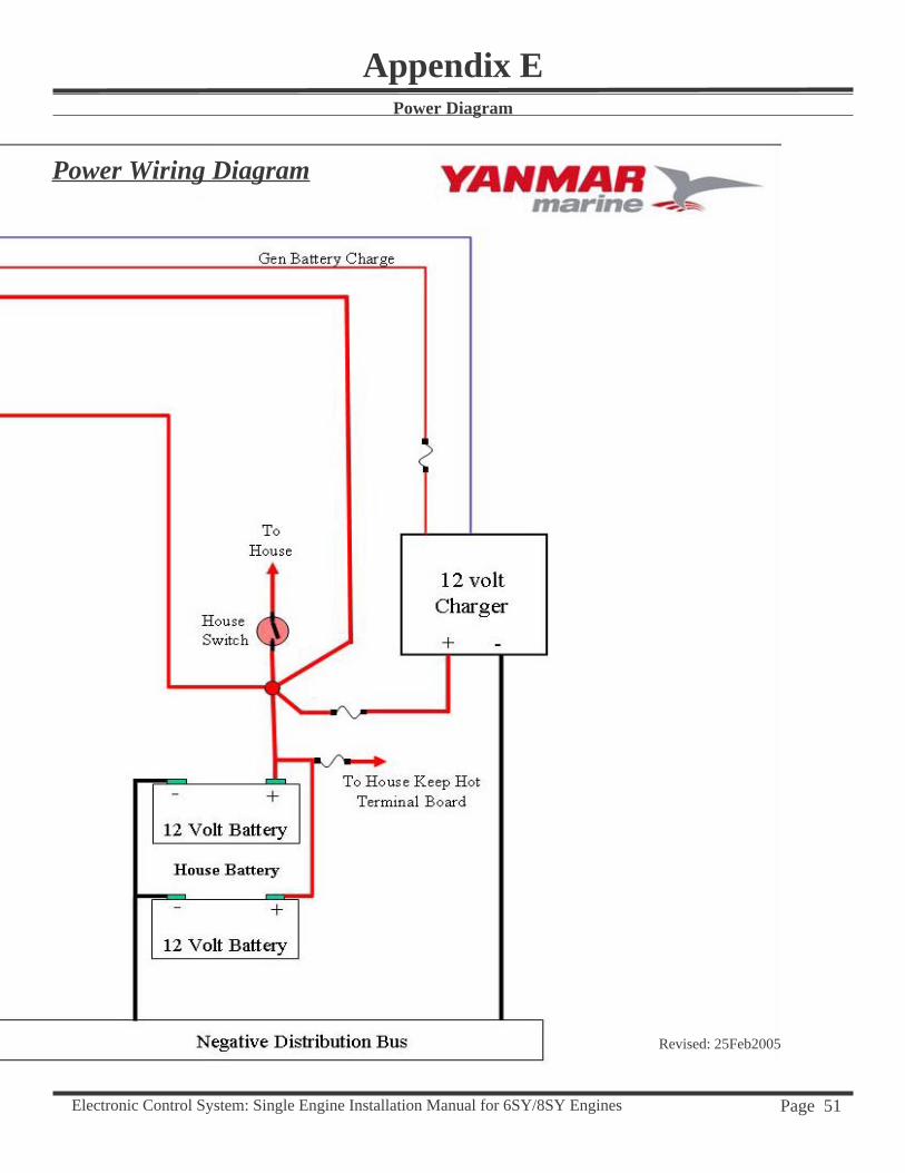
Revised: 25Feb2005
Power Wiring Diagram
Electronic Control System: Single Engine Installation Manual for 6SY/8SY Engines Page 52
Appendix FTrolling
Note: The operator must understand the limitations to the gear and is responsible for the settings.
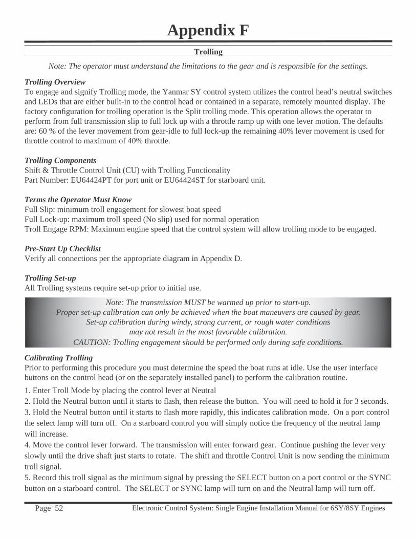
Trolling Overview To engage and signify Trolling mode, the Yanmar SY control system utilizes the control head’s neutral switches and LEDs that are either built-in to the control head or contained in a separate, remotely mounted display. The factory confi guration for trolling operation is the Split trolling mode. This operation allows the operator to perform from full transmission slip to full lock up with a throttle ramp up with one lever motion. The defaults are: 60 % of the lever movement from gear-idle to full lock-up the remaining 40% lever movement is used for throttle control to maximum of 40% throttle.
Trolling ComponentsShift & Throttle Control Unit (CU) with Trolling Functionality Part Number: EU64424PT for port unit or EU64424ST for starboard unit.
Terms the Operator Must Know Full Slip: minimum troll engagement for slowest boat speedFull Lock-up: maximum troll speed (No slip) used for normal operationTroll Engage RPM: Maximum engine speed that the control system will allow trolling mode to be engaged.
Pre-Start Up Checklist Verify all connections per the appropriate diagram in Appendix D.
Trolling Set-up All Trolling systems require set-up prior to initial use.
Note: The transmission MUST be warmed up prior to start-up.Proper set-up calibration can only be achieved when the boat maneuvers are caused by gear.
Set-up calibration during windy, strong current, or rough water conditionsmay not result in the most favorable calibration.
CAUTION: Trolling engagement should be performed only during safe conditions.
Calibrating TrollingPrior to performing this procedure you must determine the speed the boat runs at idle. Use the user interface buttons on the control head (or on the separately installed panel) to perform the calibration routine.1. Enter Troll Mode by placing the control lever at Neutral2. Hold the Neutral button until it starts to fl ash, then release the button. You will need to hold it for 3 seconds.3. Hold the Neutral button until it starts to fl ash more rapidly, this indicates calibration mode. On a port control the select lamp will turn off. On a starboard control you will simply notice the frequency of the neutral lamp will increase.4. Move the control lever forward. The transmission will enter forward gear. Continue pushing the lever very slowly until the drive shaft just starts to rotate. The shift and throttle Control Unit is now sending the minimum troll signal.5. Record this troll signal as the minimum signal by pressing the SELECT button on a port control or the SYNC button on a starboard control. The SELECT or SYNC lamp will turn on and the Neutral lamp will turn off.
Electronic Control System: Single Engine Installation Manual for 6SY/8SY Engines Page 53
6. Move the control lever back to the Neutral position. The Neutral lamp will start to blink again indicating that you can calibrate the maximum troll signal.7. Move the control lever forward. The transmission will enter forward gear. Continue pushing the lever very slowly forward. After every little push forward wait several seconds and determine 8. Record this troll signal as the maximum signal by pressing the N button. The SELECT or SYNC lamp will turn on and the Neutral lamp will turn off.9. Move the control lever back to the Neutral position. The Neutral lamp will start to blink again. 10. Completed the calibration procedure by holding the Neutral button until it turns on solid indicating that the calibration is complete.
Calibration NotesIf, during the procedure, you do not wish to keep the calibration values prior to step 10, simply power the Shift and Throttle Control Unit off and back on.
If, after using troll, you determine that when you fi rst enter idle in gear the shaft is spinning too fast, you must manually go into the trolling menu and lower the minimum signal. If the shaft is spinning too slowly you can rerun the procedure for the minimum signal calibration.
If, after using troll, you determine that the maximum trolling signal is too small, you must manually go into the trolling menu and raise the maximum signal. If the trolling signal is too large you can rerun the calibration procedure and lower this value.
Feature Selection Table
Appendix FTrolling
Control Unit Display Trolling Selection
B2 Trolling ModeB1: 100% Trolling Mode; B2: Trolling/Throttle
60 Trolling/Throttle transition (% Lever Movement)XX: Trolling/Throttle --70,60,50,40,30
40 Maximum Throttle range when trolling/throttle active20,40,60,80,100
02 Throttle engage delay (0=>2 seconds)00, 02, 04, 06, 08, 10, 12, 14, 16, 18, 20
70 Trolling engage RPM (50 RPM Steps)400 up to 800 RPM
CU Type OutputCU: Current (ZF)LT: Voltage (Twin Disc)
T1 Calibration100 – Full Trolling Current (Full Bypass) CU300 – Min Trolling Current (No Bypass) CU05 – Full Trolling Voltage (Full Bypass) 05 => 45 (0.5 to 4.50 Volts) LT45 – Min Trolling Voltage (No Bypass) 05 => 45 (0.5 to 4.50 Volts) LT
Electronic Control System: Single Engine Installation Manual for 6SY/8SY Engines Page 54
Appendix FTrolling
........
........
........
........
........
........
........
60%
40%
Trolling
Throttle
40% ThrottleFull Lock-up
Entering/Exiting Trolling1. Enter Troll Mode by placing the control lever at Neutral2. Hold the Neutral button until it starts to fl ash, then release the button. You will need to hold it for 3 seconds.3. To exit Troll Mode, place the control lever to the Neutral position and press the Neutral (N) button.
Note: While engaged in Trolling mode, Split Range Throttle (SRT) is not available.
Control Lever Range of Operation
Electronic Control System: Single Engine Installation Manual for 6SY/8SY Engines Page 55
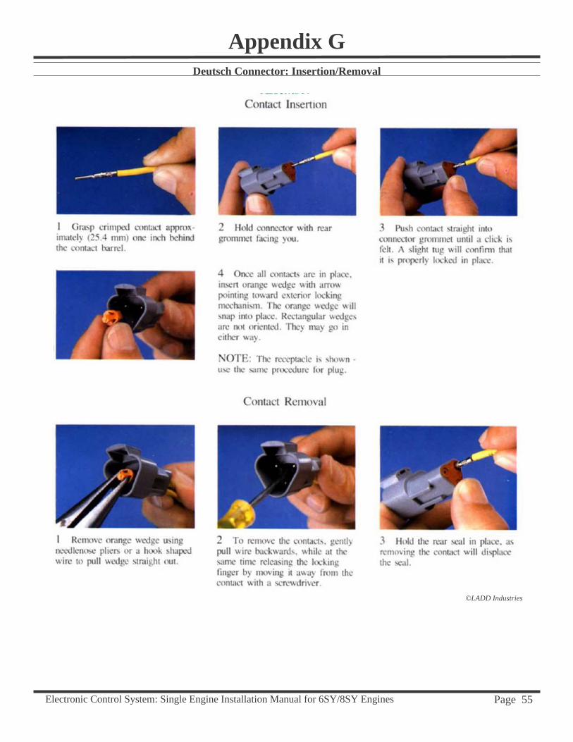
Appendix GDeutsch Connector: Insertion/Removal
©LADD Industries
Electronic Control System: Single Engine Installation Manual for 6SY/8SY Engines Page 56
Appendix HMiscellaneous
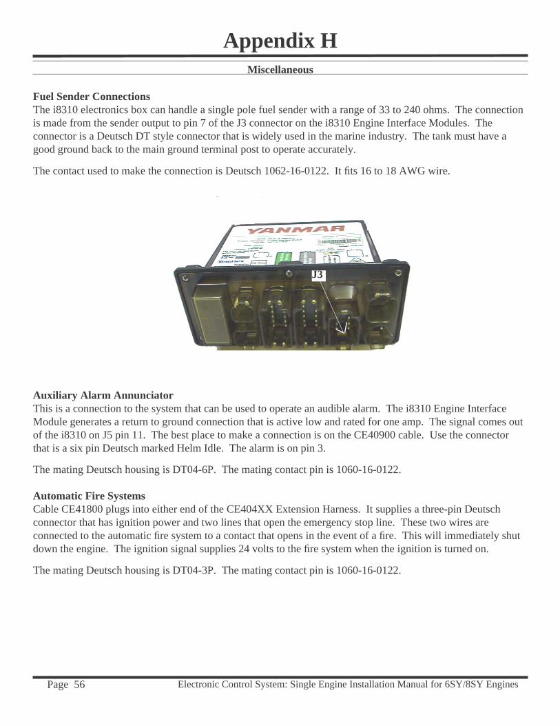
Fuel Sender ConnectionsThe i8310 electronics box can handle a single pole fuel sender with a range of 33 to 240 ohms. The connection is made from the sender output to pin 7 of the J3 connector on the i8310 Engine Interface Modules. The connector is a Deutsch DT style connector that is widely used in the marine industry. The tank must have a good ground back to the main ground terminal post to operate accurately.
The contact used to make the connection is Deutsch 1062-16-0122. It fi ts 16 to 18 AWG wire.
Auxiliary Alarm AnnunciatorThis is a connection to the system that can be used to operate an audible alarm. The i8310 Engine Interface Module generates a return to ground connection that is active low and rated for one amp. The signal comes out of the i8310 on J5 pin 11. The best place to make a connection is on the CE40900 cable. Use the connector that is a six pin Deutsch marked Helm Idle. The alarm is on pin 3.
The mating Deutsch housing is DT04-6P. The mating contact pin is 1060-16-0122.
Automatic Fire SystemsCable CE41800 plugs into either end of the CE404XX Extension Harness. It supplies a three-pin Deutsch connector that has ignition power and two lines that open the emergency stop line. These two wires are connected to the automatic fi re system to a contact that opens in the event of a fi re. This will immediately shut down the engine. The ignition signal supplies 24 volts to the fi re system when the ignition is turned on.
The mating Deutsch housing is DT04-3P. The mating contact pin is 1060-16-0122.
J3