electronic circuit breaker ess31-t-dc 24 v · electronic circuit breaker ess31-t...-dc 24 v 1651 1...
TRANSCRIPT
www.e-t-a.de
Electronic circuit breaker ESS31-T...-DC 24 V
1651 1
4
Operating data
Operating voltage UB DC 24 V (18...30 V)
Current ratings IN fixed rating: Types ESS31-TC-…: 0.5 A, 1 A, 2 A, 3 A, 3.6 A, 4 A,
6 A, 8 A, 10 A, 12 A
Standby current I0 in ON condition: typically 8 mA depending on the signal output
Trip current (bimetal) typically 0.4 A
(only in the event of a failure, until physical disconnection)
Visual status l multicoloured LED:indication Green: - device is ON (S1 = ON) load circuit connected
Orange: - overload or short circuit until electronic disconnection
Red: - device switched OFF electronically load circuit OFF - undervoltage (UB < 8 V)
OFF: - manually OFF (S1 = OFF)
load circuit physically isolated or device is dead-voltage l Potential-free signal contact l On/off position of the switch S1
Load circuitLoad output power MOSFET switching output (plus switching)
Overload and short typically 1.2 x IN circuit disconnection with active current limitation Trip times for see time/current characteristic electronic disconnection overload trip time typically 500 ms short circuit trip time depending on
current rating (see table 1)
for physical isolation typically 5 s
Temperature disconnection internal temperature monitoring with physical isolation
Undervoltage with hysteresis, no reset required: monitoring »OFF« at UB < 14 V of load output »ON« at UB > 17 V
Switch-on delay tStart typically 2 ms after each ON operation, reset and after applying of UB
Capacitive loads up to 40,000 µF
Free-wheeling diode external free-wheeling diode recommended for inductive load
Description
Technical data (Tamb = 25 °C, UB = DC – 24 V)
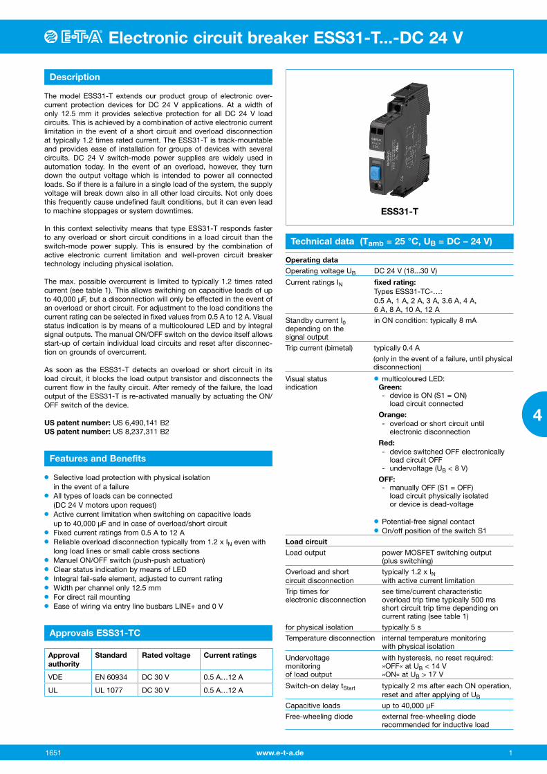
ESS31-T
The model ESS31-T extends our product group of electronic over-current protection devices for DC 24 V applications. At a width of only 12.5 mm it provides selective protection for all DC 24 V load circuits. This is achieved by a combination of active electronic current limitation in the event of a short circuit and overload disconnection at typically 1.2 times rated current. The ESS31-T is track-mountable and provides ease of installation for groups of devices with several circuits. DC 24 V switch-mode power supplies are widely used in automation today. In the event of an overload, however, they turn down the output voltage which is intended to power all connected loads. So if there is a failure in a single load of the system, the supply voltage will break down also in all other load circuits. Not only does this frequently cause undefined fault conditions, but it can even lead to machine stoppages or system downtimes.
In this context selectivity means that type ESS31-T responds faster to any overload or short circuit conditions in a load circuit than the switch-mode power supply. This is ensured by the combination of active electronic current limitation and well-proven circuit breaker technology including physical isolation.
The max. possible overcurrent is limited to typically 1.2 times rated current (see table 1). This allows switching on capacitive loads of up to 40,000 µF, but a disconnection will only be effected in the event of an overload or short circuit. For adjustment to the load conditions the current rating can be selected in fixed values from 0.5 A to 12 A. Visual status indication is by means of a multicoloured LED and by integral signal outputs. The manual ON/OFF switch on the device itself allows start-up of certain individual load circuits and reset after disconnec-tion on grounds of overcurrent.
As soon as the ESS31-T detects an overload or short circuit in its load circuit, it blocks the load output transistor and disconnects the current flow in the faulty circuit. After remedy of the failure, the load output of the ESS31-T is re-activated manually by actuating the ON/OFF switch of the device.
US patent number: US 6,490,141 B2US patent number: US 8,237,311 B2
Features and Benefits
Approvals ESS31-TC
l Selective load protection with physical isolation in the event of a failure
l All types of loads can be connected (DC 24 V motors upon request)
l Active current limitation when switching on capacitive loads up to 40,000 µF and in case of overload/short circuit
l Fixed current ratings from 0.5 A to 12 A l Reliable overload disconnection typically from 1.2 x IN even with
long load lines or small cable cross sections l Manuel ON/OFF switch (push-push actuation) l Clear status indication by means of LED l Integral fail-safe element, adjusted to current ratingl Width per channel only 12.5 mml For direct rail mountingl Ease of wiring via entry line busbars LINE+ and 0 V
Approval authority
Standard Rated voltage Current ratings
VDE EN 60934 DC 30 V 0.5 A…12 A
UL UL 1077 DC 30 V 0.5 A…12 A
Electronic circuit breaker ESS31-T...-DC 24 VElectronic circuit breaker ESS31-T...-DC 24 V
www.e-t-a.de 2 1651
4
Technical data (Tamb = 25 °C, UB = DC – 24 V)
Parallel connection of not allowed several load outputs
Signal output ESS31-TC-001/-002Electrical data potential-free auxiliary contact
max. DC 30 V / 2 A min. DC 12 V / 10 mA
Standard condition UB is applied and switch S1 is ON and LED green overload, no short circuit
OFF condition LED off device switched off (switch S1 is OFF) load circuit physically isolated no operating voltage UB
Fault condition LED orange overload conditoins > 1.2 times rated current until electronic disconnection
Fault condition LED red electronic disconnection upon overload, short circuit or undervoltage
ESS31-TC-001 single signal, make contact contact open, terminal 13-14
ESS31-TC-002 single signal, break contact contact closed, terminal 11-12
General dataFail-safe element back-up fuse for ESS31-T.. not required
due to integral redundant fail-safe ele-ment (protective element)
Terminals LINE+ / LOAD+ / 0V - Screw terminals max. cable cross section M4 - flexible with wire end ferrule w/wo plastic sleeve 0.5 – 10 mm2 - multi-lead connection (2 identical cables) rigid / flexible 0.5 – 4 mm2 - flexible with wire end ferrule without plastic sleeve 0.5 – 2.5 mm2 - flexible with TWIN wire end ferrule with plastic sleeve 0.5 – 6 mm2 - wire stripping length 10 mm - tightening torque (EN 60934) 1.5 – 1.8 Nm
Terminals aux. contacts - Screw terminals M3 - max. cable cross section - flexible with wire end ferrule w/wo plastic sleeve 0.25 – 2.5 mm2 - wire stripping length 8 mm - tightening torque (EN 60934) 0.5 – 0.6 Nm
Housing material moulded
Mounting symmetrical rail to EN 50022-35 x 7.5
Ambient temperature 0...+50 °C (without condensation, cf. EN 60204-1)
Storage temperature -20...+70 °C
Humidity 96 hrs / 95% RH 40 °C to IEC 60068-2-78-Cab
climate class 3K3 to EN 60721
Vibration 3 g test to IEC 60068-2-6, test Fc ,
Protection class housing IP20 EN 60529 terminals IP20 EN 60529
EMC requirements emission: EN 61000-6-3 (EMC directive, CE logo) susceptibility: EN 61000-6-2
Insulation co-ordination 0.5 kV / pollution degree 2 (IEC 60934) reinforced insulation in operating area
Dielectric strength max. DC 30 V (load circuit)
Insulation resistance > 100 MΩ (DC 500 V) between (OFF condition) LINE (+) and LOAD (+)
Dimensions (w x h x d) 12.5 x 80 x 83 mm (tolerances to DIN ISO 286 part 1 IT13)
Mass approx. 70 g
Type No.ESS31 Electronic Circuit Breaker, with current limitation Mounting TC rail mounting, with auxiliary contact Version 0 with physical isolation in the event of a failure Signal input 0 without signal input Signal output 1 auxiliary make contact
(min. 12 V/10 mA; max. 30 V/2 A) 2 auxiliary break contact
(min. 12 V/10 mA; max. 30 V/2 A) Operating voltage DC 24 V voltage rating DC 24 V Current rating 0.5 A 1 A 2 A 3 A 3.6 A 4 A 6 A 8 A 10 A 12 A
ESS31 - TC - 0 0 1 - DC 24 V - 6 A ordering example
Class 2Meets requirement for Class 2 current limitation(ESS31-T...-0,5 A/1 A/2 A/3 A/3,6 A)
Order numbering code
Application note
l The user has to ensure that the cable cross section of the load circuit in question complies with the current rating of the ESS31-T used.
l In addition special precautions must be taken in the system or machine (e.g. use of a safety PLC) which reliably prevent an automatic re-start of parts of the system (cf. Machinery Directive 2006/42/EG and EN 60204-1, Safety of Machinery). In the event of a failure (short circuit/overload) the load circuit will be discon-nected electronically with physical isolation of the contacts by the ESS31-T.

www.e-t-a.de
Electronic circuit breaker ESS31-T...-DC 24 V
1651 3
4
Electronic circuit breaker ESS31-T...-DC 24 V
Effect of the ambient temperature on the tripping characteristics
ambient temperature T [°C] 0 +10 +23 +30 +40 +50
temperature factor 0.88 0.93 1.0 1.04 1.12 1.22
Table 1: Voltage drop, current limitation, trip times, fail-safe element, max. load current
Table 2: ESS31-T.. - versions
current rating IN
typical voltage drop UON at IN
active current limitation typically
triptimeISC
typically 1)
triptimeIOL
typically 2)
fail-safe element
max. load current at 100 % ON duty
TAMB = 40 °C
TAMB = 50 °C
0.5 A 90 mV 1,2 x IN 500 ms 500 ms 2 A 0.5 A 0.5 A
1 A 100 mV 1,2 x IN 500 ms 500 ms 2 A 1 A 1 A
2 A 110 mV 1,2 x IN 500 ms 500 ms 4 A 2 A 2 A
3 A 150 mV 1,2 x IN 500 ms 500 ms 6.3 A 3 A 3 A
3.6 A 155 mV 1,2 x IN 350 ms 500 ms 6.3 A 3.6 A 3.6 A
4 A 160 mV 1.2 x IN 280 ms 500 ms 6.3 A 4 A 4 A
6 A 170 mV 1,2 x IN 150 ms 500 ms 10 A 6 A 5 A
8 A 190 mV 1.2 x IN 280 ms 500 ms 15 A 8 A 7 A
10 A 210 mV 1.2 x IN 200 ms 500 ms 15 A 10 A 9 A
12 A 220 mV 1.2 x IN 110 ms 500 ms 20 A 12 A 10.8 A
Note: When mounted side-by-side without convection the devices can only carry max. 80 % of their rated current continuously (100 % ON duty) due to thermal effect.
1) short circuit2) overload
Version Signal input Signal output:
Signal output F (signal contact) Status output SF
ESS31-... without control inputON/OFF +24 V
Control IN+
reset input+24 V
RE
without single signalmake con-
tact(normally open NO)
single signalbreak con-
tact(normally
closed NC)
without statusOUT
+24 V = OK
statusOUT
0 V = OK
-TC -001 X X X
-TC -002 X X X
→
Electronic circuit breaker ESS31-T...-DC 24 VElectronic circuit breaker ESS31-T...-DC 24 V
www.e-t-a.de 4 1651
4
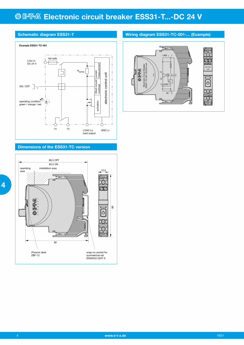
Schematic diagram ESS31-T Wiring diagram ESS31-TC-001-... (Example)
LOAD (+)load output
operating conditiongreen / orange / red
ON / OFF
Line (+)DC 24 V
Example ESS31-TC-001
fail-safe
Rsense
GND (-)
activ
atio
n
elec
tron
ic c
ontr
ol u
nit
curr
ent
mea
sure
men
tS
hort
circ
uit/
over
load
14 13
XX
XX
ES
S31
-TC
-001
-DC
24V-
xxA
Ele
ctro
nic
Circ
uit
Bre
aker
DC 24VxxA
2 LOAD+
1413
I>
LINE
+LOAD
+
2
13
14
0V 3
1
GE
RM
AN
Y
Dimensions of the ESS31-TC version
Phoenix label ZBF-12
snap-on socket for symmetrical railEN50022-35X7.5
12,5
80
80
89,5 OFF
83,5 ON
operatingarea
installation area
GE
RM
AN
Y

www.e-t-a.de
Electronic circuit breaker ESS31-T...-DC 24 V
1651 5
4
Electronic circuit breaker ESS31-T...-DC 24 V
ESS31-T Signal inputs / outputs (wiring diagrams)
Typical time/current characteristic (Tamb = 25 °C)
ESS31-TC-002-.....ESS31-TC-001-.....
The auxiliary contacts are shown in OFF or fault condition
without signal inputwith signal output fsingle singnal, make contact
without signal inputwith signal output fsingle singnal, break contact
operating condition13-14 closedfault condition 13-14 open
operating condition 11-12 openfault condition 11-12 closed
I>
LINE
+LOAD
+
2
13
14
0V 3
1
I>
LINE
+LOAD
+
2
11
12
0V 3
1
trip time dependson rated current(see table 1)
IK
10000
1000
1 2 4
...times rated current
100
10
10,5
0,1
0,013 5
max. 1.35 x IN
disconnection andcurrent limitationtypically 1.2 x IN
min. 1.05 x IN
0
trip
tim
e in
sec
ond
s
l The overload trip time is typically 500 ms (e.g. ESS31-T-…-6 A)l The electronic current limitation typically begiins in at 1.2 x IN
This means: under all overload conditions (independent of power supply and load circuit resistance) typically 1.2 times rated current is applied until disconnection. The corresponding current limitation value ILimit depends on the current rating of the device IN.
l Without the current limitation getting into effect at typically 1.2 x IN there would be a much higher overcurrent in the event of an over-load or short circuit.
l Reset of the circuit breaker is only possible approximately 10 sec after tripping.
Electronic circuit breaker ESS31-T...-DC 24 VElectronic circuit breaker ESS31-T...-DC 24 V
www.e-t-a.de 6 1651
4
Mounting examples for ESS31-T
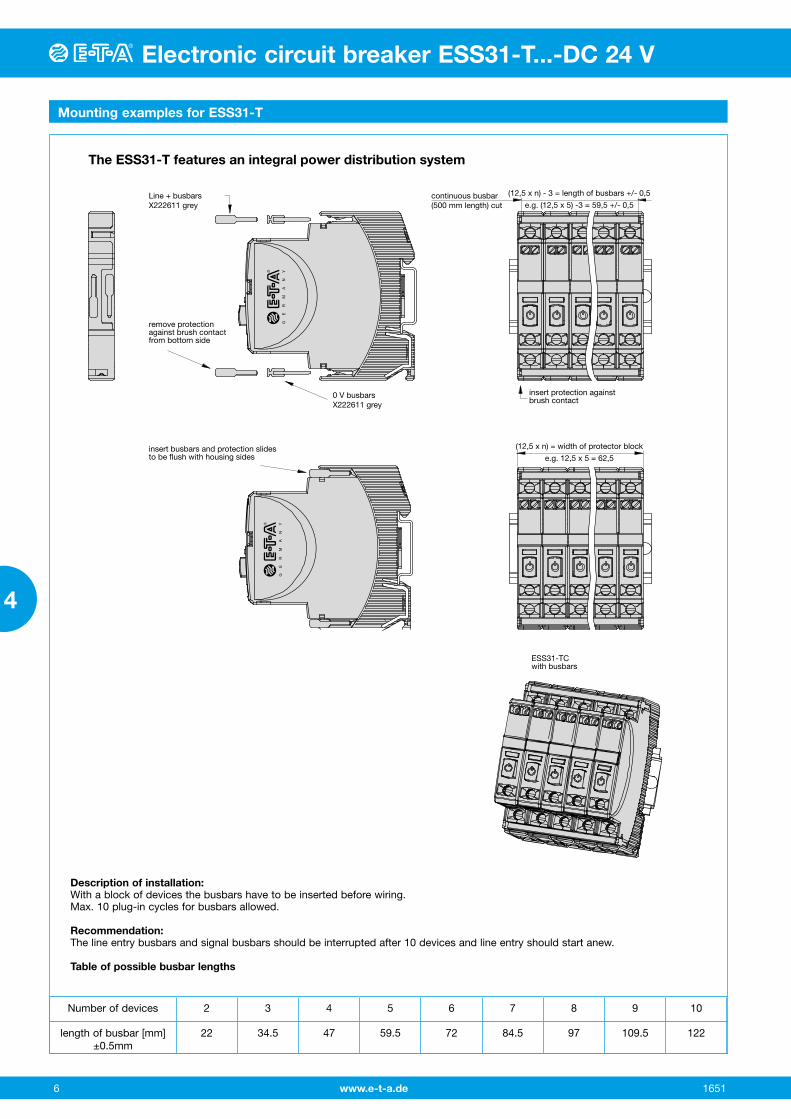
The ESS31-T features an integral power distribution system
ESS31-TCwith busbars
insert busbars and protection slidesto be flush with housing sides
continuous busbar(500 mm length) cut
(12,5 x n) - 3 = length of busbars +/- 0,5
e.g. (12,5 x 5) -3 = 59,5 +/- 0,5
(12,5 x n) = width of protector block
e.g. 12,5 x 5 = 62,5
Line + busbars X222611 grey
0 V busbars X222611 grey
remove protection against brush contact from bottom side
insert protection againstbrush contact
GE
RM
AN
YG
ER
MA
NY
Description of installation:With a block of devices the busbars have to be inserted before wiring.Max. 10 plug-in cycles for busbars allowed.
Recommendation:The line entry busbars and signal busbars should be interrupted after 10 devices and line entry should start anew.
Table of possible busbar lengths
Number of devices 2 3 4 5 6 7 8 9 10
length of busbar [mm] ±0.5mm
22 34.5 47 59.5 72 84.5 97 109.5 122
www.e-t-a.de
Electronic circuit breaker ESS31-T...-DC 24 V
1651 7
4
Electronic circuit breaker ESS31-T...-DC 24 V
Accessories / Technical data
Busbars for LINE and 0 V ampacity with one input Imax 50 A (recommendation: central supply) ampacity with two inputs Imax 63 A
grey insulated, length: 500 mm X 222 611 02
Busbars for LINE and 0 V grey insulated max. 10 plug-in cycles allowed
X 222 611 22 (block of 2 ESS31-Ts), length: 22 mm Packaging unit: 10 pcs
X 222 611 34 (block of 3 ESS31-Ts), length: 34.5 mm Packaging unit: 10 pcs
X 222 611 47 (block of 4 ESS31-Ts), length: 47 mm Packaging unit: 10 pcs
X 222 611 59 (block of 5 ESS31-Ts), length: 59.5 mm Packaging unit: 10 pcs
X 222 611 72 (block of 6 ESS31-Ts), length: 72 mm Packaging unit: 4 pcs
X 222 611 97 (block of 8 ESS31-Ts), length: 97 mm Packaging unit: 4 pcs
X 222 611 12 (block of 10 ESS31-Ts), length: 122 mm Packaging unit: 4 pcs
7,5
Insulated wire bridge (for aux. contact) optional as jumper for group signalling (series connection of make contacts 13 - 14) X 223 108 01 Packaging unit: 10 pcs
Description
The ESS31-T has an integral power distribution system. The following wirings can be carried out with different plug-in type busbars:
l LINE +(DC 24 V)l 0 V Important: The electronic devices ESS31-T require a 0 V connection.
Connector bus link –K10suitable for auxiliary contacts (series connection)X 210 589 02 (1.5 mm2, brown),
~2.
76
50 pin lugs toDIN 46230tinned copper
ø2.5.099
~70
All dimensions without tolerances are for reference only. In the interest of improved design, performance and cost effectiveness, the right to make changes in these specifications with-out notice is reserved. Product markings may not be exactly as the ordering codes. Errors and omissions excepted.
Passive supply module for LINE+ and 0 V (without protection) optional for all types ESS31-T versions allowing to
connect the loads in question to all ESS31-T.
Ampacity Ima 50 A Max. cable cross section 0.5 - 10 mm2
Technical Data see terminals of ESS31-T AD-TX-EM01
max
. 50
A
LINE+ 1
0V 3
Ein
spei
sem
odul
Sup
ply
Mod
ule
AD
-TX
-EM
01
AD-TX-EM01
GE
RM
AN
Y
Electronic circuit breaker ESS31-T...-DC 24 V
www.e-t-a.de 8 1651
4