electronic brake control valve equipment qualification
TRANSCRIPT

A P T A S T A N D A R D S D E V E L O P M E N T P R O G R A M
STANDARD American Public Transportation Association
1300 I Street, NW, Suite 1200 East, Washington, DC 20005
APTA PR-M-S-028-21 First Published: January 15, 2021 PRESS Mechanical Working Group
“This document represents a common viewpoint of those parties concerned with its provisions, namely transit operating/planning agencies, manufacturers, consultants, engineers, and general interest groups. APTA standards are mandatory to the extent incorporated by an applicable statute or regulation. In some cases, federal and/or state regulations govern portions of a transit system’s operations. In cases where this is a conflict or contradiction between an applicable law or regulation and this document, consult with a legal advisor to determine which document takes precedence.” © 2020 The North American Transportation Services Association (NATSA) and its parent organization APTA. No part of this publication may be reproduced in any form, in an electronic retrieval system or otherwise, without prior written permission of NATSA.
Electronic Brake Control Valve Equipment Qualification—Testing Requirements Abstract: This standard contains the minimum testing requirements for brake control valve (26C emulation) and electronically controlled pneumatic (ECP) brake systems operating on passenger cars that are part of the general railroad system.
Keywords: brake, ECP, railcar, train
Summary: This Standard contains the test procedures and reporting requirements for the introduction of a new control valve for use with industry 26C functions and the interoperability among suppliers of 26-type brake equipment.
Scope and purpose: This document identifies the minimum testing or other evidence required for submittal to APTA for the acceptance of new 26C emulation/electronically controlled pneumatic control valves. This standard ensures that APTA-approved 26C emulation and ECP brake systems from different manufacturers are interoperable and meet a high level of safety and reliability. The overall objectives of this standard are to define test requirements specific to U.S. trains operating in passenger service equipped with 26C emulation/ECP; to ensure that trains equipped with APTA-approved brake systems from different manufacturers are interoperable and function consistently and uniformly; and to ensure that APTA-approved electronic brake systems meet a high standard for safety and reliability.

© 2021 American Public Transportation Association | ii
Table of Contents
Participants................................................................................................................................................... iii Introduction ................................................................................................................................................... v
1. Description of target braking system for passenger applications ........................................................ 1 1.1 Description of ECP braking system .......................................................................................................... 1 1.2 Description of 26C emulation braking system .......................................................................................... 1 1.3 Description of APTA Reporting Requirements......................................................................................... 1
2. Test rack configuration ........................................................................................................................... 2 2.1 AAR- locomotive and cab car rack setup (RP-505 Compliant) ................................................................. 2 2.2 AAR single car rack setup (RP-505 Compliant) ....................................................................................... 4 2.3 Test data acquisition ................................................................................................................................ 6
3. Single car test rack performance testing................................................................................................ 6 3.1 Setup pressures ........................................................................................................................................ 6 3.2 Single car rack test ................................................................................................................................... 6
4. 24-car train rack test .............................................................................................................................. 14 4.1 Test setup .............................................................................................................................................. 14 4.2 24 Car train test rack procedure.............................................................................................................. 14 4.3 Brake application and release (ECP only)............................................................................................... 16
5. Interoperability demonstration between qualified systems................................................................. 20 5.1 Test location .......................................................................................................................................... 20 5.2 Emulation functionality ......................................................................................................................... 20 5.3 ECP functionality .................................................................................................................................. 20 Related APTA standards.............................................................................................................................. 21 References................................................................................................................................................... 21 Definitions .................................................................................................................................................. 21 Abbreviations and acronyms ........................................................................................................................ 23 Document history ........................................................................................................................................ 24
List of Figures and Tables
Figure 1 Locomotive/Cab Car Test Rack Pneumatic Setup .......................... 2 Figure 2 Locomotive/Cab Car Test Rack Electrical Setup ........................... 3 Figure 3 Car Test Rack Pneumatic Setup..................................................... 4 Figure 4 Car Test Rack Electrical Setup ...................................................... 5 Table 1 Configuration of Control Valve ...................................................... 6 Table 2 Brake Pipe Reductions .................................................................... 6 Table 3 Brake Cylinder Pressures .............................................................. 12 Table 4 Emulation Brake Application Scenarios ........................................ 15 Table 5 ECP Brake Application Scenarios ................................................. 16 Table 6 Scenarios for Brake Cycling Test .................................................. 18

© 2021 American Public Transportation Association | iii
Participants The American Public Transportation Association greatly appreciates the contributions of the Brake Task Group of the PRESS Mechanical Working Group, which provided the primary effort in the drafting of this document.
At the time this standard was completed, the working group included the following members:
Jonathan Bernat, New York Air Brake, Document Lead
Carl Atencio, Denver Transit Operators Frank Banko, WSP USA Paul Bender, Wabtec Corp. B.A. “Brad” Black, Virginkar & Associates Michael Burshtin, retired David Carter, New Jersey Transit John Condrasky, retired
Brendan Crowley, New York Air Brake Adam Eby, Amtrak Elizabeth Hensley, Wabtec Corp. Paul Jamieson, retired Robert Jones, Stadler Rail Group Francesco Maldari, MTA Long Island Rail Road Marla O’Connor, LTK Engineering Services
At the time this standard was completed, the PRESS Mechanical Working Group included the following members:
David Warner, SEPTA, Chair Rudy Vazquez, Amtrak, Vice Chair Paul Jamieson, Retired, Secretary
Mohamed Alimirah, Metra Carl Atencio, Denver Transit Operators Frank Banko, WSP USA Michael Barnes, Jacobs Taft Bearden, Atkins Global NA David Bennett, Capital Metro. Trans. Authority Jonathan Bernat, New York Air Brake B.A. “Brad” Black, Virginkar & Associates Stephen Bonina, WSP USA Glenn Brandimarte, ORX Rail Tony Brown, MTA of Harris County Richard Bruss, retired Michael Burshtin, retired Greg Buzby, SEPTA Dennis Cabigting, STV Inc. Elvin Calderon, Denver Transit Operators Paul Callaghan, Transport Canada Gordon Campbell, Crosslinx Transit Solutions Kevin Carmody, STV Inc. David Carter, New Jersey Transit Steve Cavanaugh, Metrolinx (GO Transit)
Steve Chrismer, Amtrak Dion Church, Atkins Global John Condrasky, retired Joshua Coran, Talgo Inc. Michael Craft, Paragon Robotics Brendan Crowley, New York Air Brake Ryan Crowley, Atkins Global NA Richard Curtis, Curtis Engineering Consulting Steven Dedmon, Standard Steel LLC Joe Di Liello, VIA Rail Canada Inc. David Diaz, LTK Engineering Services Adam Eby, Amtrak Phillippe Etchessahar, ALSTOM Transport Gary Fairbanks, Federal Railroad Administration Robert Festa, MTA Long Island Rail Road Steve Finegan, Atkins Global NA Gavin Fraser, Jacobs Francesco Fumarola, ALSTOM Transport Edward Gacsi, New Jersey Transit Joe Gagliardino, Arcosa Sebastien Geraud, ALSTOM Transport

© 2021 American Public Transportation Association | iv
Jeffrey Gordon, Federal Railroad Administration Guillaume Ham-Livet, ALSTOM Transport Nick Harris, LTK Engineering Services Jasen Haskins, Atkins Global NA James Herzog, LTK Engineering Services Kenneth Hesser, LTK Engineering Services Lew Hoens, MTA Metro-North Railroad Christopher Holliday, STV Inc. George Hud, LTK Engineering Services John Janiszewski, LTK Engineering Services MaryClara Jones, Transportation Technology Center Robert Jones, Stadler Rail Group Larry Kelterborn, LDK Advisory, Inc. Joseph Kenas, Bombardier Transportation Peter Klauser, Vehicle Dynamics Heinz-Peter Kotz, Siemens Mobility, Inc. Scott Kramer, Arcosa Tammy Krause, Atkins Globa NA Pallavi Lal, LTK Engineering Services Peter Lapre, Federal Railroad Administration Nicolas Lessard, Bombardier Transportation Cameron Lonsdale, Standard Steel, LLC Daniel Luskin, Amtrak Chris Madden, Amtrak Francesco Maldari, MTA Long Island Rail Road Brian Marquis, Volpe Natl. Trans. Systs. Center Eloy Martinez, LTK Engineering Services Francis Mascarenhas, Metra Raynald Masse, Reseau de Transport Metropolitain Robert May, LTK Engineering Services Ronald Mayville, Simpson Gumpertz & Heger, Inc. Richard Mazur, Wabtec Corp. Patrick McCunney, Atkins Global NA Gerard McIntyre, Knorr Brake Corp. Bryan McLaughlin, New York Air Brake William Minnick, Omni Strategy Luke Morscheck, LTK Engineering Services Karl Mullinix, Knorr Brake Corp. Joshua Munoz, LTK Engineering Services Paul O’Brien, Transit District of Utah Chase Patterson, Voith Turbo, Inc. Joe Patterson, Amsted Rail John Pearson, LTK Engineering Services
Martin Petzoldt, Railroad Friction Products, LLC James Pilch, Standard Steel, LLC Ian Pirie, STV Inc. Brian Pitcavage, LTK Engineering Services Peter Reumueller, Siemens Mobility, Inc. Danial Rice, Wabtec Corp. Steven Roman, LTK Engineering Services Carol Rose, STV Inc. Thomas Rusin, Rusin Consulting Thomas Rutkowski, Virgin Trains Mehrdad Samani, LTK Engineering Services Gerhard Schmidt, Siemens Mobility, Inc. Martin Schroeder, Jacobs Richard Seaton, TDG Transit Design Group Frederic Setan, ALSTOM Transport Patrick Sheeran, LTK Engineering Services Melissa Shurland, Federal Railroad Administration David Skillman, Amtrak Benjamin Spears, LTK Engineering Services Rick Spencer, Knorr Brake Corp. Rex Springston, AECOM Mark Stewart, LTK Engineering Services Jonathan Sunde, Strato Inc. Lukasz Szymsiak, VIA Rail Canada, Inc. Ali Tajaddini, Federal Railroad Administration Jeff Thompson, SEPTA Matthew Todt, Amsted Rail Ron Truitt, HTSI Anthony Ursone, UTC/Rail & Airsources, Inc. Frank Ursone, UTC/Rail & Airsources, Inc. Michael Von Lange, UTC/Rail & Airsources, Inc. Gary Wagner, Amsted Rail Michael Wetherell, McKissack & McKissack Brian Whitten, Atkins Global NA Kristian Williams, Amtrak Todd Williams, Penn Machine Co. Nicholas Wilson, Transportation Technology Center Tim Wineke, Knorr Brake Corp. Reggie Wingate, Knorr Brake Corp. Aleksey Yelesin, Amtrak Gregory Yovich, NICTD Steven Zuiderveen, Federal Railroad Administration
Project team Nathan Leventon, American Public Transportation Association Narayana Sundaram, American Public Transportation Association

© 2021 American Public Transportation Association | v
Introduction This introduction is not part of APTA PR-M-S-028-21, “Brake Control Valve Equipment Qualification—Testing Requirements.”
This standard applies to all:
1. Railroads that operate intercity or commuter passenger train service on the general railroad system of transportation; and
2. Railroads that provide commuter or other short-haul rail passenger train service in a metropolitan or suburban area, including public authorities operating passenger train service.
This standard does not apply to:
1. Rapid transit operations in an urban area that are not connected to the general railroad system of transportation;
2. Tourist, scenic, historic or excursion operations, whether on or off the general railroad system of transportation;
3. Operation of private cars, including business/office cars and circus trains; or 4. Railroads that operate only on track inside an installation that is not part of the general railroad
system of transportation.

APTA PR-M-S-028-21 Brake Control Valve Equipment Qualification—Testing Requirements
© 2021 American Public Transportation Association 1
Brake Control Valve Equipment Qualification—Testing Requirements
1. Description of target braking system for passenger applications 1.1 Description of ECP braking system An ECP brake system is a train-powered braking system actuated by compressed air and controlled by electronic signals originating from a lead locomotive or cab car. The electronic signals are used to communicate service and emergency brake applications, as well as to control power and receive feedback from other devices in the train. Since brake commands are derived from electronic signals, the brake pipe will typically remain charged and will provide backup brake commands.
The “cable-based” ECP brake system provides communications and a potential source of power to all the ECP brake devices in the train via a two-conductor electric trainline that spans the entire length of the train. The system provides shorter response times to braking commands and includes support for graduated releases and reapplications. The system responds appropriately to undesired separation or malfunction of hoses, cabling, or brake pipe.
1.2 Description of 26C emulation braking system Emulation is a mode that ECP systems can enter in the event that trainline messages are not received from the locomotive head end unit (HEU). In this mode of operation, the car control device (CCD) will monitor brake pipe (BP) pressure and develop/release brake cylinder (BC) pressure in response to changes in the BP pressure.
Emulation may provide two modes of operation: passenger and freight compatibility. Alternate performance characteristics may be required based on customer needs; this document outlines a basic set of requirements for two modes of operation common to the passenger market.
The primary source of power for emulation operation is the nominal 74 VDC main car battery. The ECP control valve battery shall provide a secondary power source.
1.3 Description of APTA Reporting Requirements The report provided to APTA shall include details; including:
• Part numbers / serial numbers / descriptions of the brake valve used and peripheral equipment used on the Locomotive / Cab car test rack.
• Part numbers / serial numbers / descriptions of the control valve(s) used and peripheral equipment used on the car test racks.
• Part numbers / serial numbers / descriptions of the test equipment used (pressure transducers, Data Acquisition system, etc.).

APTA PR-M-S-028-21 Brake Control Valve Equipment Qualification—Testing Requirements
© 2021 American Public Transportation Association 2
• Deviations to the test set-up from setup prescribed in section (2) of this standard.
Reporting of specific data / plots as referenced in the test procedures shall be presented; mirroring the procedural order of this standard.
Steps requiring the verification of pressures shall require the indication of “PASS/FAIL” and the recorded pressure.
2. Test rack configuration 2.1 AAR- locomotive and cab car rack setup (RP-505 Compliant) Locomotive test rack shall be equipped with 26 type brake equipment for locomotive or their equivalents. Locomotive equipment shall be equipped with hardware/functionality for ECP in accordance with APTA PR-M-S-021-19.
2.1.1 Piping schematic FIGURE 1
Locomotive/Cab Car Test Rack Pneumatic Setup
AAR ElectronicBrake Valve
Main Reservoir
Brake Pipe (1-¼” IPS)
Main Reservoir Equalizing Pipe (1” IPS)
1" ID
1" ID
¾”
ID
Test point / Pressure
Transducer
AAR Vent Valve
AAR Vent Valve
Test
poi
nt /
Pres
sure
Tr
ansd
ucer
Brake Cylinder
Test point / Pressure
Transducer
¾”
ID
Brake Cylinder
¾”
ID
EnunciatedCutout
EnunciatedCutout
Test
poi
nt /
Pres
sure
Tr
ansd
ucer
2.1.2 Volumes 1. Main reservoir sizing shall be at manufacturer’s discretion. 2. BP shall be 100 equivalent ft 1¼ in. Sch. 80 pipe or equivalent (between car angle cocks). End-of-
locomotive hose shall be standard 33 in. AAR M-601 hose. Branch pipe length to the brake valve shall not exceed 72 in. in length.
3. 16/BC pilot volume shall be at manufacturer’s discretion. 4. BC volume shall be at manufacturer’s discretion. 5. Piping materials and construction shall conform with APTA PR-M-S-029-21, “Pneumatic Piping for
Vehicles.”

APTA PR-M-S-028-21 Brake Control Valve Equipment Qualification—Testing Requirements
© 2021 American Public Transportation Association 3
2.1.3 Electrical schematic FIGURE 2
Locomotive/Cab Car Test Rack Electrical Setup
AAR Brake Valve
ECP Trainline ECP TrainlineCenter Junction / Car Interface
EOC Junction
EOC Junction
Brake Cylinder
¾”
ID
Brake Cylinder
¾”
ID
EnunciatedCutout
EnunciatedCutout
2.1.4 Pressure transducer placement 1. MR: Pressure transducer shall be located ≤ 2 equivalent feet from the brake valve. 2. BP: Pressure transducer shall be located ≤ 2 equivalent feet from the brake valve.

APTA PR-M-S-028-21 Brake Control Valve Equipment Qualification—Testing Requirements
© 2021 American Public Transportation Association 4
2.2 AAR single car rack setup (RP-505 Compliant) 2.2.1 Piping schematic
FIGURE 3 Car Test Rack Pneumatic Setup
Control Valve Under Test
Supply Reservoir
16/BC Pilot Reservoir
16
6
EX EX
30
J-Relay
1" ID
1" IP
Venting Device
1" ID
¾” ID
Test point / Pressure
Transducer
¾”
ID
Test
poi
nt /
Pres
sure
Tr
ansd
ucer
Test point / Pressure
Transducer
¾”
ID
EnunciatedCutout
EnunciatedCutout
Test
poi
nt /
Pres
sure
Tr
ansd
ucer
Brake Pipe (1-¼” IPS)
Main Reservoir Equalizing Pipe (1” IPS)
1" ID
¾”
ID
Brake Cylinder
Brake Cylinder
2.2.2 Volumes 1. Supply reservoir shall be sized to accommodate the larger of either four FS BC applications plus one
EMER BC application or 11,360 cu. in. ± 500 cu. in.). 2. BP shall be 100 ft 1¼ in. Sch. 80 pipe (between car angle cocks). End-of-car hose shall be standard
22 in. AAR M-601. Branch pipe length to the control valve shall be 22 to 72 in. (per AAR S-400). 3. 16/BC pilot volume shall be at manufacturer’s discretion.
2.2.2.1 BC Maximum BC volume (simulated tread plus disc brake):
[900 ± 100 cu. In. + 93 equivalent feet ¾ in. ID piping] or [1750 ± 100 cu. In. + inline choke (equivalent to 93 equivalent feet ¾ in. ID piping)]
Minimum BC volume (simulated disc brake only):
[300 ± 100 cu. in. + 93 equivalent feet ¾ in. ID piping] or [1150 ± 100 cu. In. + inline choke (equivalent to 93 equivalent feet ¾ in. ID piping)]
APTA PR-M-S-028-21 Brake Control Valve Equipment Qualification—Testing Requirements
© 2021 American Public Transportation Association 5
Piping materials and construction shall conform with APTA PR-M-S-029-21, “Pneumatic Piping for Vehicles.”
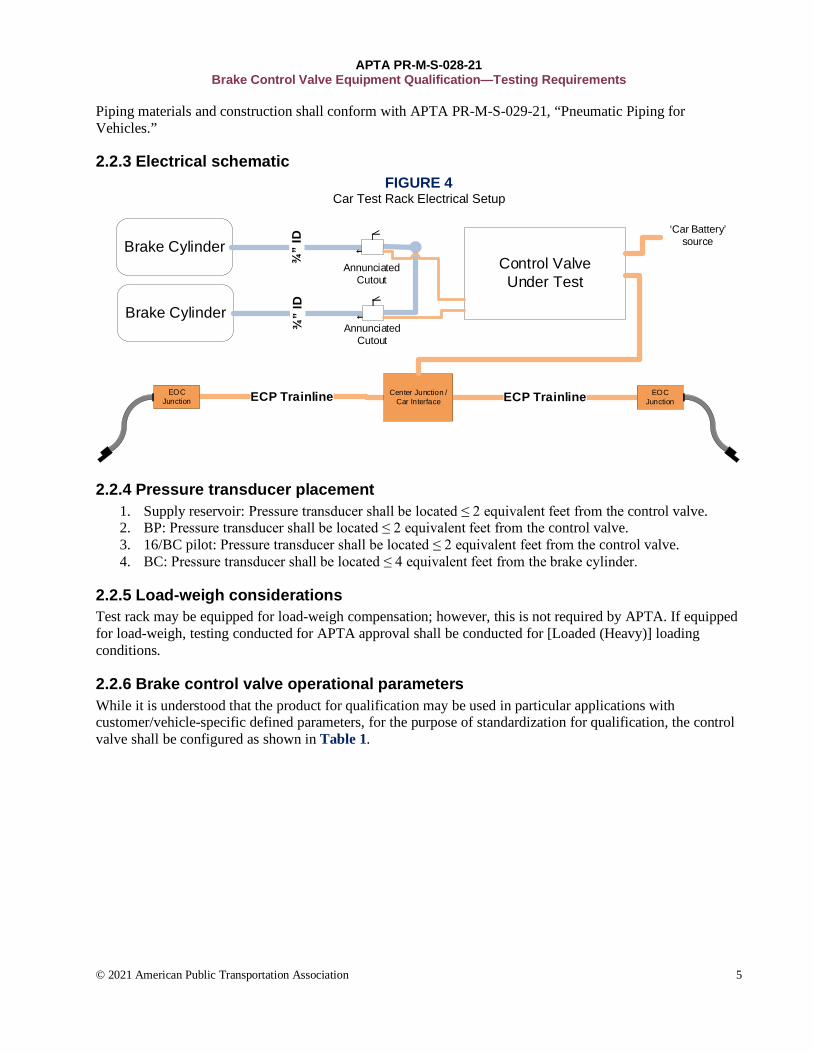
2.2.3 Electrical schematic FIGURE 4
Car Test Rack Electrical Setup
Control Valve Under Test
ECP Trainline ECP TrainlineCenter Junction / Car Interface
EOC Junction
EOC Junction
‘Car Battery’ sourceBrake Cylinder
¾”
IDBrake Cylinder
¾”
ID
AnnunciatedCutout
AnnunciatedCutout
2.2.4 Pressure transducer placement 1. Supply reservoir: Pressure transducer shall be located ≤ 2 equivalent feet from the control valve. 2. BP: Pressure transducer shall be located ≤ 2 equivalent feet from the control valve. 3. 16/BC pilot: Pressure transducer shall be located ≤ 2 equivalent feet from the control valve. 4. BC: Pressure transducer shall be located ≤ 4 equivalent feet from the brake cylinder.
2.2.5 Load-weigh considerations Test rack may be equipped for load-weigh compensation; however, this is not required by APTA. If equipped for load-weigh, testing conducted for APTA approval shall be conducted for [Loaded (Heavy)] loading conditions.
2.2.6 Brake control valve operational parameters While it is understood that the product for qualification may be used in particular applications with customer/vehicle-specific defined parameters, for the purpose of standardization for qualification, the control valve shall be configured as shown in Table 1.

APTA PR-M-S-028-21 Brake Control Valve Equipment Qualification—Testing Requirements
© 2021 American Public Transportation Association 6
TABLE 1 Configuration of Control Valve
Brake Application BP reduction (psi)
Resulting 16/BC pilot pressure
(psi)
Release 0 0 - 1
Minimum 8 16 ± 4
Suppression 17 38 ± 4
Full service 27 67 ± 4
Handle off BP to <20 83 ± 4
Emergency BP to 0 83 ± 4
Emergency limiting valve (ELV) BP to <33 87 ± 4
2.3 Test data acquisition 1. Event switch for data acquisition timestamp reference. 2. Pressure transducers shall be sampled at a rate of 100 Hz (or higher). 3. Pressure transducers with associated cables shall be calibrated to have a minimum device accuracy of
1 percent full-scale deflection, 0 psig to 160 psig. 4. All data recording equipment must be calibrated and maintained in good operating condition.
3. Single car test rack performance testing 3.1 Setup pressures
1. Main reservoir/supply reservoir: MR/SR pressure governor shall be set to 125 to 145 psi. 2. Default feed valve: Default feed valve shall be set to 110 ± 1 psi. 3. BP reduction: Brake pipe reductions for testing shall be defined per Table 2:
TABLE 2 Brake Pipe Reductions
Brake Application
BP reduction (psi)
Resulting BP pressure
(psi)
Release 0 110 ± 1
Minimum 8 102 ± 1
Suppression 17 93 ± 1
Full service 27 83 ± 1
Handle off ER to 0 ≤ 15
Emergency ER to 0 0 - 1
3.2 Single car rack test 3.2.1 Test rack configuration 3.2.1.1 (1) Locomotive rack(s)
1. Locomotive to be configured as defined in AAR Locomotive & Cab Car Rack setup (RP-505 Compliant) Definition section.

APTA PR-M-S-028-21 Brake Control Valve Equipment Qualification—Testing Requirements
© 2021 American Public Transportation Association 7
3.2.1.2 (5) Single-car test rack(s) • One test rack required for 26C emulation testing. • Five test rack(s) required for ECP testing. • Each individual car to be configured as defined in AAR Single Car Rack setup (RP-505 Compliant)
Definition section.
3.2.1.3 (1) ECP EOT device 1. ECP EOT device may be either:
• Standalone EOT device. • Last car in test consist (if equipped with EOT functionality).
3.2.1.4 Definition of pressure transducer placement 1. Pressures shall be recorded from the car test rack under test.
3.2.1.5 Main reservoir/supply reservoir 1. MR/SR pressure governor shall be set to 125 to 145 psi. 2. MR pressure supply shall be available to the car test rack under test.
3.2.1.6 Default feed valve 1. Default feed valve shall be set to 110 ± 1 psi.
3.2.1.7 Test rack power supply 1. “Car battery” voltage supplied to the control valve shall be 46 ± 1 VDC (IEEE-1476 Standard for
Passenger Train Auxiliary Power Systems Interfaces. 2. ECP trainline voltage supplied to the control valve shall conform with APTA PR-M-S-023-19:
• Low voltage: 22.8 to 30.0 VDC. • High voltage: 225 to 248 VDC.
3.2.2 Single-car emulation performance test 1. Single-car performance (performance curves). 2. Include visibility of reaction time, time to target and linearity.
3.2.2.1 Emergencies Break in two (pneumatic) and recovery
1. Verify that BP is charged to 110 ± 1 psi and MR to 125 psi or greater on the operator display and/or cab gauges.
2. Wait for pressure stabilization. 3. Start recording using the DAQ. 4. Initiate a pneumatic emergency application from a non-EAB source. 5. Wait for pressure stabilization. 6. Recover the emergency and charge BP to release. 7. Stop recording using the DAQ. 8. Pass/fail reporting requirements:
• Plot BP and 16/BC pilot and BC pressures vs. time for the application. Plot from 5 seconds prior to Emergency initiation to 45 seconds after begins to increase.
• Verify that car 16/BC pilot pressure increases to 83 ± 4 psi with the emergency application.
• Verify that car 16/BC pilot pressure reduces to zero and BP has recharged to 110 psi.

APTA PR-M-S-028-21 Brake Control Valve Equipment Qualification—Testing Requirements
© 2021 American Public Transportation Association 8
• (Passenger emulation) Verify that 16/BC pilot pressure increase rate does not exceed 52 psi/s.
• (Freight compatibility, if applicable) Verify that 16/BC pilot pressure increase rate does not exceed 18 psi/s.
Break in two (pneumatic; no control valve power) and recovery 1. Remove power to the control valve and control valve powers off. 2. Verify that BP is charged to 110 ± 1 psi and MR to 125 psi or greater on the operator display and/or
cab gauges. 3. Wait for pressure stabilization. 4. Start recording using the DAQ. 5. Initiate a pneumatic emergency application from a non-EAB source. 6. Wait for pressure stabilization. 7. Recover the emergency and charge BP to release. 8. Stop recording using the DAQ. 9. Pass/fail reporting requirements:
• Plot BP, 16/BC pilot, and BC pressures vs. time for the application. Plot from 5 seconds prior to control valve power removal to 45 seconds after BP begins to increase.
• Verify that car 16/BC pilot pressure increases to ELV psi (87 ± 4 psi) with the emergency application.
• Verify that car 16/BC pilot pressure reduces to zero and BP has recharged to 110 psi.
Emulation override (pneumatic; no control valve power) and recovery 1. Start recording using the DAQ. 2. Reduce BP to ~0 psi. 3. Wait for pressure stabilization. 4. Remove power to the control valve/control valve powers off. 5. Wait for pressure stabilization. 6. Apply power to the control valve/control valve powers on. 7. Wait for pressure stabilization. 8. Stop recording using the DAQ. 9. Pass/fail reporting requirements:
• Plot BP, 16/BC pilot, and BC pressures vs. time for the application. Plot from 5 seconds prior to initiation of BP reduction to 45 seconds after control valve power is re-applied.
• Verify that car 16/BC pilot pressure increases to ELV psi (87 ± 4 psi) with the emergency application.
• Verify that car 16/BC pilot pressure reduces to 83 ± 4 psi with the control valve wake-up.
3.2.2.2 Supply reservoir charging 1. Verify that BP is charged to 90 ± 1 psi and MR to 125 psi or greater on the operator display and/or
cab gauges. 2. Reduce BP to FS pressure. 3. Close MR supply to the car. 4. Start recording using the DAQ. 5. Reduce car MR pressure to 90 ± 5 psi. 6. Wait for pressure stabilization. 7. Increase BP to release 8. Stop recording using the DAQ. 9. Pass/fail reporting requirements:
• Verify that car SR pressure does not increase when BP pressure < SR pressure.

APTA PR-M-S-028-21 Brake Control Valve Equipment Qualification—Testing Requirements
© 2021 American Public Transportation Association 9
• Verify that car SR pressure increases when BP pressure > SR pressure. 3.2.2.3 Default feed valve
1. Remove power to the control valve/control valve powers off. 2. Set brake valve feed valve to 90 psi. 3. Verify that BP is charged to 90 ± 1 psi and MR to 125 psi or greater on the operator display and/or
cab gauges. 4. Wait for pressure stabilization. 5. Start recording using the DAQ. 6. Apply power to the control valve/control valve powers on. 7. Move brake valve to FS position. 8. Wait for pressure stabilization. 9. Move brake valve to release position. 10. Wait for pressure stabilization. 11. Ensure that 16/BC pilot reduces to 0 psi. 12. Set brake valve feed valve to 110 psi and ensure that BP is charged to 110 ± 1 psi. 13. Verify that 16/BC pilot pressure remains zero. 14. Move brake valve to FS position. 15. Wait for pressure stabilization. 16. Move brake valve to SUPP position. 17. Wait for pressure stabilization. 18. Increase BP to release. 19. Wait for pressure stabilization. 20. Ensure that 16/BC pilot reduces to 0 psi. 21. Stop recording using the DAQ. 22. Pass/fail reporting requirements:
• Plot BP, 16/BC pilot, and BC pressures vs. time for the application. Plot from 5 seconds prior to control valve power is applied to 45 seconds after BP begins to increase (with Feed valve set to 110 psi).
• For feed valve of 90 psi: Verify that 16/BC pilot pressure reduces to 0 psi with the control valve power initially applied.
• For feed valve of 90 psi: Verify that 16/BC pilot pressure increases to 67 ± 4 psi with the FS application.
• For feed valve of 90 psi: Verify that 16/BC pilot pressure reduces to 0 psi with the release.
• For feed valve adjustment to 110 psi: Verify that 16/BC pilot pressure remains 0 psi with the feed valve adjustment.
• For feed valve of 110 psi: Verify that 16/BC pilot pressure increases to 67 ± 4 psi with the FS application.
• For feed valve of 110 psi: Verify that 16/BC pilot pressure reduces to 38 ± 4 psi with the release to suppression.
• For feed valve of 110 psi: Verify that 16/BC pilot pressure reduces to 0 psi with the release.
3.2.2.4 Emergency transition 1. Verify that BP is charged to 110 ± 1 psi and MR to 125 psi or greater on the operator display and/or
cab gauges. 2. Wait for pressure stabilization. 3. Start recording using the DAQ. 4. Move brake valve to HO position.

APTA PR-M-S-028-21 Brake Control Valve Equipment Qualification—Testing Requirements
© 2021 American Public Transportation Association 10
5. Wait for pressure stabilization. 6. Ensure that 16/BC pilot transitions to emergency pressure when BP is ~35 ± 2 psi. 7. Stop recording using the DAQ. 8. Pass/fail reporting requirements:
• Plot BP, 16/BC pilot, and BC pressures vs. time for the application. Plot from 5 seconds prior to initiation of automatic handle movement (BP reduction) to time 45 seconds after BC begins to increase to Emergency threshold.
• Verify that all 16/BC pilot pressure increases to 83 ± 4 when BP is ~35 ± 2 psi.
3.2.2.5 Minimum subsequent BP apply 1. Verify that BP is charged to 110 ± 1 psi and MR to 125 psi or greater on the operator display and/or
cab gauges. 2. Wait for pressure stabilization. 3. Start recording using the DAQ. 4. Move the automatic handle to the MIN position. 5. Wait for pressure stabilization. 6. Make a 1 ± 0.5 psi reduction to equalizing reservoir. 7. Wait for pressure stabilization. 8. Repeat steps 6 and 7 until the automatic handle is in the SUPP position. 9. Stop recording using the DAQ. 10. Move the automatic handle to the REL position. 11. Pass/fail reporting requirements:
• Plot BP, 16/BC pilot, and BC pressures vs. time for the application. Plot from 5 seconds prior to initiation of automatic handle movement to MIN to 45 seconds after automatic handle movement to SUPP.
• Verify that 16/BC pilot pressure builds to 16 ± 4 psi with the automatic handle in minimum position.
• Verify that 16/BC pilot pressure increases with each automatic application effort; increase command until FS 16/BC pilot is achieved.
• Verify that 16/BC pilot pressure develops at 6.9 to 3.1 psi for each 1.0 psi reduction in BP.
3.2.2.6 16 pressure build rate, freight operation (if applicable) 1. Verify that BP is charged to 110 ± 1 psi and MR to 125 psi or greater on the operator display and/or
cab gauges. 2. Wait for pressure stabilization. 3. Start recording using the DAQ. 4. Move the automatic handle to the FS position. 5. Wait for pressure stabilization. 6. Stop recording using the DAQ. 7. Move the automatic handle to the REL position. 8. Pass/fail reporting requirements
• Plot BP, 16/BC pilot, and BC pressures vs. time for the application. Plot from 5 seconds prior to initiation of automatic handle movement to FS to 45 seconds after automatic handle movement to FS.
• Verify that 16/BC pilot pressure increases at a rate of 6 ± 1 psi/s.

APTA PR-M-S-028-21 Brake Control Valve Equipment Qualification—Testing Requirements
© 2021 American Public Transportation Association 11
3.2.2.7 Release requirements (APTA PR-M-S-020-17, Section 2.4) Graduated release
1. Verify that BP is charged to 110 ± 1 psi and MR to 125 psi or greater on the operator display and/or cab gauges.
2. Wait for pressure stabilization. 3. Start recording using the DAQ. 4. Move the automatic handle to the FS position. 5. Wait for pressure stabilization. 6. Make a 3 ± 0.5 psi increase to equalizing reservoir. 7. Wait for pressure stabilization. 8. Repeat steps 6 and 7 until automatic handle is in the MIN position. 9. Stop recording using the DAQ. 10. Move the automatic handle to the REL position. 11. Pass/fail reporting requirements:
• Plot BP, 16/BC pilot, and BC pressures vs. time for the application. Plot from 5 seconds prior to initiation of automatic handle movement to FS to 45 after automatic handle to MIN.
• Verify in the period after the initial 3 psi increase until BP is approximately ~96 psi that subsequent increases in BP reduce 16/BC pilot pressure by 4 to 5 psi per 1.0 psi BP increase.
• Verify that 16/BC pilot pressure reduces to zero when BP is in the range (MIN BP) through (MIN BP – 5 psi).
Direct release (if applicable) 1. Verify that BP is charged to 110 ± 1 psi and MR to 125 psi or greater on the operator display and/or
cab gauges. 2. Wait for pressure stabilization. 3. Start recording using the DAQ. 4. Move the automatic handle to the FS position. 5. Wait for pressure stabilization. 6. Make a 3 +1/−0 psi increase to equalizing reservoir. 7. Wait for pressure stabilization. 8. Stop recording using the DAQ. 9. Move the automatic handle to the REL position. 10. Pass/fail reporting requirements:
• Plot BP, 16/BC pilot, and BC pressures vs. time for the application. Plot from 5 seconds prior to initiation of automatic handle movement to FS to 45 seconds after automatic handle movement to from FS (out of FS).
• Verify that 16/BC pilot releases to 0 to 1 psi with 3 psi increase in BP.
3.2.2.8 Exiting emulation (APTA PR-M-S-020-17, Section 2.5) 1. Verify: Upon the initiation of a valid ECP HEU beacon, the car shall connect and communicate with
the head end per APTA PR-M-S-021-17, Section 2.5.1.2.
3.2.2.9 Control valve shutdown (APTA PR-M-S-020-17, Section 2.6) 1. Verify: With the removal of power source(s) to the control valve, the control valve can be set
manually or automatically to a powered-down state.
APTA PR-M-S-028-21 Brake Control Valve Equipment Qualification—Testing Requirements
© 2021 American Public Transportation Association 12
3.2.2.10 Preliminary quick service (APTA PR-M-S-020-17, Section 2.7.1) 1. Verify that BP is charged to 110 ± 1 psi and MR to 125 psi or greater on the operator display and/or
cab gauges. 2. Wait for pressure stabilization. 3. Locate the preliminary quick service exhaust on the control valve under test. 4. Move the automatic handle to the MIN position. 5. Pass/fail reporting requirements:
• Verify that preliminary quick service exhaust is present while BP is reducing to the MIN reduction pressure and has stopped by the time MIN brake has been achieved.
3.2.3 ECP performance • Single-car performance (performance curves). • Include visibility of reaction time, time to target and linearity. • Perform testing per APTA PR-M-S-026-19 and ensure that all applicable sections pass.
3.2.3.1 Deviations from APTA PR-M-S-026-19 procedure 1. Section 2.2: only the supplier qualifying the control valve under test is required for this testing (i.e.,
Supplier B). 2. Section 3: Testing is required to be conducted only once; just one HEU supplier is expected to be
present (until interoperability testing). 3. Section 3: Test consist is required only to include the HEU; single-car test rack with control valve for
qualification; four single-car test racks with control valve for qualification or alternate supplier ECP control valve; and an ECP EOT device.
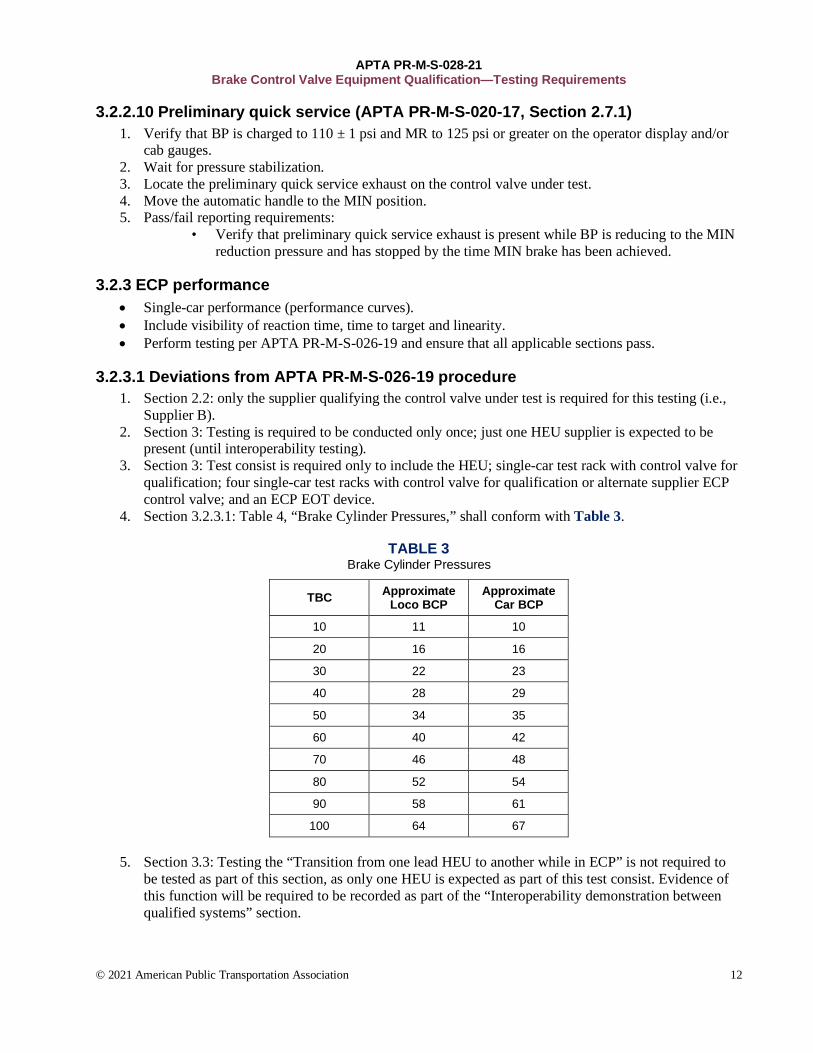
4. Section 3.2.3.1: Table 4, “Brake Cylinder Pressures,” shall conform with Table 3.
TABLE 3 Brake Cylinder Pressures
TBC Approximate Loco BCP
Approximate Car BCP
10 11 10
20 16 16
30 22 23
40 28 29
50 34 35
60 40 42
70 46 48
80 52 54
90 58 61
100 64 67
5. Section 3.3: Testing the “Transition from one lead HEU to another while in ECP” is not required to be tested as part of this section, as only one HEU is expected as part of this test consist. Evidence of this function will be required to be recorded as part of the “Interoperability demonstration between qualified systems” section.

APTA PR-M-S-028-21 Brake Control Valve Equipment Qualification—Testing Requirements
© 2021 American Public Transportation Association 13
3.2.3.2 Emergencies Break in two (pneumatic) and recovery
1. Verify that BP is charged to 110 ± 1 psi and MR to 125 psi or greater on the operator display and/or cab gauges.
2. Wait for pressure stabilization. 3. Start recording using the DAQ. 4. Initiate a pneumatic emergency application from a non-EAB source. 5. Wait for pressure stabilization. 6. Recover the emergency and charge BP to release. 7. Stop recording using the DAQ. 8. Pass/fail reporting requirements:
• Plot 16/BC pilot and BC pressures vs. time for the application. Plot from 5 seconds prior to Emergency initiation to 45 seconds after BP begins to increase.
• Verify that car 16/BC pilot and BC pressure increases to 83 ± 4 psi with the emergency application.
• Verify that car 16/BC pilot pressure reduces to zero. • Verify that 16/BC pilot pressure increase rate does not exceed 52 psi/s.
Minimum subsequent BP apply 1. Verify that BP is charged to 110 ± 1 psi and MR to 125 psi or greater on the operator display and/or
cab gauges. 2. Wait for pressure stabilization. 3. Start recording using the DAQ. 4. Move the automatic handle to the MIN position. 5. Wait for pressure stabilization. 6. Make a 15 TBC increase in brake command. 7. Wait for pressure stabilization. 8. Repeat steps 6 and 7 until the automatic handle is in the SUPP position. 9. Stop recording using the DAQ. 10. Move the automatic handle to the REL position. 11. Pass/fail reporting requirements:
• Plot 16/BC pilot and BC pressures vs. time for the application. Plot from 5 seconds prior to initiation of automatic handle movement to MIN to 45 seconds after automatic handle movement to SUPP.
• Verify that 16/BC pilot pressure builds to 16 ± 4 psi with the automatic handle in MIN position.
• Verify that 16/BC pilot pressure increases with each automatic application effort increase command until FS 16/BC pilot is achieved.
• Verify that 16/BC pilot pressure develops at 9 +/-4 psi for each 15 TBC increase.
3.2.3.3 Release requirements (APTA PR-M-S-020-17, Section 2.4) Graduated release
1. Verify that BP is charged to 110 ± 1 psi and MR to 125 psi or greater on the operator display and/or cab gauges.
2. Wait for pressure stabilization. 3. Start recording using the DAQ. 4. Move the automatic handle to the FS (100 TBC) position. 5. Wait for pressure stabilization. 6. Reduce TBC by 15.

APTA PR-M-S-028-21 Brake Control Valve Equipment Qualification—Testing Requirements
© 2021 American Public Transportation Association 14
7. Wait for pressure stabilization. 8. Repeat steps 6 and 7 until the automatic handle is in the MIN position. 9. Stop recording using the DAQ. 10. Move the automatic handle to the REL position. 11. Pass/fail reporting requirements:
• Plot 16/BC pilot and BC pressures vs. time for the application. Plot from 5 seconds prior to initiation of automatic handle movement to FS to time 45 seconds after automatic handle movement to MIN.
• Verify in the period after the initial 15 TBC reduction until AUTO handle = MIN (TBC=10) that subsequent reductions in TBC reduce 16/BC pilot and BC pressure by 9 +/-4 psi for every 15 TBC reduction
• Verify that 16/BC pilot pressure reduces to 16 ± 4 psi with AUTO handle is in the MIN range.
4. 24-car train rack test Train rack testing is intended to verify the functionality and performance of the brake control device in a consist of 24 cars under test.
4.1 Test setup 4.1.1 (1) locomotive rack(s) Locomotive to be configured as defined in AAR Locomotive & Cab Car Rack setup (RP-505
Compliant) definition section.
4.1.2 (24) single-car test rack(s) Each individual car to be configured as defined in AAR Single Car Rack setup (RP-505 Compliant)
Definition section.
4.1.3 (1) ECP EOT device ECP EOT device may be either:
• Standalone EOT device. • Last car in test consist (if equipped with EOT functionality).
4.1.4 Definition of pressure transducer placement Pressures shall be recorded from the locomotive, first car, last car and up to every sixth car within the
test consist.
4.1.5 Main reservoir/supply reservoir MR/SR pressure governor shall be set to 125 to 145 psi. MR pressure supply shall be available to all vehicles in test consist.
4.1.6 Default feed valve Default feed valve shall be set to 110 ± 1 psi.
4.2 24 Car train test rack procedure Testing shall be conducted in 26C emulation and ECP.

APTA PR-M-S-028-21 Brake Control Valve Equipment Qualification—Testing Requirements
© 2021 American Public Transportation Association 15
4.2.1 Brake application and release (emulation only) 1. Testing shall be conducted for the brake application scenarios in all operation modes referenced in
Table 4:
TABLE 4 Emulation Brake Application Scenarios
Brake Scenario Brake Application Pressure
Stabilization Time [s]
1 Minimum service 60
2 Suppression 60
3 Full service 60
4 Handle off 120
5 Automatic emergency 120
4.2.2 Brake application and release procedure
1. Verify that BP is charged to 110 ± 1 psi and MR to 125 psi or greater on the operator display and/or cab gauges.
2. Wait for pressure stabilization. 3. Start recording using the DAQ. 4. Move the automatic handle to the brake application position being tested. 5. Allow the required time (Table 4) for pressure stabilization. 6. Move the automatic handle to the REL position. 7. Stop recording using the DAQ. 8. Pass/fail reporting requirements:
• Plot BP, 16/BC pilot, and BC pressures vs. time for each brake scenario application, for all recorded vehicles. Plot from time 5 seconds prior to automatic handle movement to [pressure stabilization time] seconds after brake application automatic handle movement.
• Plot BP, 16/BC pilot, and BC pressures vs. time for each brake scenario release, for all recorded vehicles. Plot from 5 seconds prior to automatic handle movement to [pressure stabilization time] seconds after automatic handle movement to REL.
4.2.2.1 For all cars (brake scenario 1) 1. For apply: Verify that 16/BC pilot pressures stabilize to 16 ± 4 psi for all vehicles. 2. For apply: Verify that 16/BC pilot builds to 90 percent of MIN BC in 8 ± 4 s for all vehicles. 3. For release: Verify that 16/BC pilot pressures stabilize to 0 to 1 psi for all vehicles. 4. For release: Verify that 16/BC pilot pressures reduce to 5 psi BC in 6 ± 5 s for all vehicles.
4.2.2.2 For all cars (brake scenario 2) 1. For apply: Verify that 16/BC pilot pressures stabilize to 38 ± 4 psi for all vehicles. 2. For apply: Verify that 16/BC pilot builds to 90 percent of suppression BC in 10 ± 4 s for all vehicles. 3. For release: Verify that 16/BC pilot pressures stabilize to 0 to 1 psi for all vehicles. 4. For release: Verify that 16/BC pilot pressures reduce to 5 psi BC in 8 ± 6 s for all vehicles.
4.2.2.3 For all cars (brake scenario 3) 1. For apply: Verify that 16/BC pilot pressures stabilize to 67 ± 4 psi for all vehicles. 2. For apply: Verify that 16/BC pilot builds to 90 percent of FS BC in 13 ± 4 s for all vehicles.

APTA PR-M-S-028-21 Brake Control Valve Equipment Qualification—Testing Requirements
© 2021 American Public Transportation Association 16
3. For release: Verify that 16/BC pilot pressures stabilize to 0 to 1 psi for all vehicles. 4. For release: Verify that 16/BC pilot pressure reduces to 5 psi BC in 12.5 ± 7 s for all vehicles.
4.2.2.4 For all cars (brake scenario 4) 1. For apply: Verify that 16/BC pilot pressures stabilize to 83 ± 4 psi for all vehicles. 2. For release: Verify that 16/BC pilot pressures stabilize to 0 to 1 psi for all vehicles.
4.2.2.5 For all cars (brake scenario 5) 1. For apply: Verify that 16/BC pilot pressures stabilize to 83 ± 4 psi for all vehicles. 2. For apply: Verify that 16/BC pilot builds to 90 percent of EMER BC in 8 ± 1.5 s for all vehicles. 3. For release: Verify that 16/BC pilot pressures stabilize to 0 to 1 psi for all vehicles.
4.3 Brake application and release (ECP only) Testing shall be conducted for the following brake application scenarios in all operation modes referenced:
TABLE 5 ECP Brake Application Scenarios
Brake Scenario Brake Application Pressure
Stabilization Time [s]
1 Minimum service 60
2 Suppression 60
3 Full service 60
4 Handle off 120
5 Automatic emergency 120
4.3.1 Brake application and release procedure 1. Verify that BP is charged to 110 ± 1 psi and MR to 125 psi or greater on the operator display and/or
cab gauges. 2. Wait for pressure stabilization. 3. Start recording using the DAQ. 4. Move the automatic handle to the brake application position. 5. Allow the required time (Table 5) for pressure stabilization. 6. Move the automatic handle to the FS position. 7. Allow the required time (Table 5) for pressure stabilization. 8. Move the automatic handle to the REL position. 9. Stop recording using the DAQ. 10. Pass/fail reporting requirements:
• Plot BP, 16/BC pilot, and BC pressures vs. time for each brake scenario application, for all recorded vehicles. Plot from 5 seconds prior to automatic handle movement to [pressure stabilization time] seconds after automatic handle movement to FS.
• Plot BP, 16/BC pilot, and BC pressures vs. time for each brake scenario release, for all recorded vehicles. Plot from 5 seconds prior to automatic handle movement to [pressure stabilization time] seconds after automatic handle movement to REL.
4.3.1.1 For all cars (brake scenario 1) 1. For apply: Verify that 16/BC pilot pressures stabilize to 16 ± 4 psi for all vehicles.

APTA PR-M-S-028-21 Brake Control Valve Equipment Qualification—Testing Requirements
© 2021 American Public Transportation Association 17
2. For apply: Verify that 16/BC pilot builds to 90 percent of MIN BC in 3 ± 2 s for all vehicles. 3. For release: Verify that 16/BC pilot pressures stabilize to 0 to 1 psi for all vehicles. 4. For release: Verify that 16/BC pilot reduces to 5 psi BC in 3 ± 2 s for all vehicles.
4.3.1.2 For all cars (brake scenario 2) 1. For apply: Verify that 16/BC pilot pressures stabilize to 38 ± 4 psi for all vehicles. 2. For apply: Verify that 16/BC pilot builds to 90 percent of suppression BC in 4 ± 2 s for all vehicles. 3. For release: Verify that 16/BC pilot pressures stabilize to 0 to 1 psi for all vehicles. 4. For release: Verify that 16/BC pilot reduces to 5 psi BC in 4 ± 2 s for all vehicles.
4.3.1.3 For all cars (brake scenario 3) 1. For apply: Verify that 16/BC pilot pressures stabilize to 67 ± 4 psi for all vehicles. 2. For apply: Verify that 16/BC pilot builds to 90 percent of FS BC in 5.5 ± 2.5 s for all vehicles. 3. For release: Verify that 16/BC pilot pressures stabilize to 0 to 1 psi for all vehicles. 4. For release: Verify that 16/BC pilot reduces to 5 psi BC in 5.5 ± 2.5 s for all vehicles.
4.3.1.4 For all cars (brake scenario 4) 1. For apply: Verify that 16/BC pilot pressures stabilize to 83 ± 4 psi for all vehicles. 2. For apply: Verify that 16/BC pilot builds to 90 percent of ECP EMER BC in 4 ± 2 s for all vehicles. 3. For release: Verify that 16/BC pilot pressures stabilize to 0 to 1 psi for all vehicles.
4.3.1.5 For all cars (brake scenario 5) 1. For apply: Verify that 16/BC pilot pressures stabilize to 83 ± 4 psi for all vehicles. 2. For apply: Verify that 16/BC pilot builds to 90 percent of EMER BC in 3 ± 2 s for all vehicles. 3. For release: Verify that 16/BC pilot pressures stabilize to 0 to 1 psi for all vehicles.
4.3.2 Graduated application 1. Verify that BP is charged to 110 ± 1 psi and MR to 125 psi or greater on the operator display and/or
cab gauges. 2. Wait for pressure stabilization. 3. Start recording using the DAQ. 4. Move the automatic handle to the MIN position. 5. Wait for pressure stabilization. 6. Make a 3 ± 1 psi reduction to equalizing reservoir or increase TBC 15 ± 2, based on the ECP display
information. 7. Wait for pressure stabilization. 8. Repeat steps 6 and 7 until the automatic handle is in the FS position. 9. Stop recording using the DAQ. 10. Move the automatic handle to the REL position. 11. Pass/fail reporting requirements:
• Plot BP, 16/BC pilot, and BC pressures vs. time for the application, for all recorded vehicles. Plot from 5 seconds prior to automatic handle movement 45 seconds after final automatic handle movement.
• For all cars: Verify that 16/BC pilot pressures increase for all vehicles with each automatic application effort increase command until FS 16/BC pilot is achieved.
• For all cars: Verify that 16/BC pilot pressures stabilize to 67 ± 4 psi for all vehicles while the automatic handle is in the FS position.

APTA PR-M-S-028-21 Brake Control Valve Equipment Qualification—Testing Requirements
© 2021 American Public Transportation Association 18
4.3.3 Graduated release 1. Verify that BP is charged to 110 ± 1 psi and MR to 125 psi or greater on the operator display and/or
cab gauges. 2. Wait for pressure stabilization. 3. Start recording using the DAQ. 4. Move the automatic handle to the FS position. 5. Wait for pressure stabilization. 6. Make a 3 ± 1 psi increase to equalizing reservoir or decrease TBC 15 ± 2, based on the ECP display
information. 7. Wait for pressure stabilization. 8. Repeat steps 6 and 7 until the automatic handle is in the MIN position. 9. Wait for pressure stabilization. 10. Move the automatic handle to the REL position. 11. Wait for pressure stabilization. 12. Stop recording using the DAQ. 13. Pass/fail reporting requirements:
• Plot BP, 16/BC pilot, and BC pressures vs. time for the application, for all recorded vehicles. Plot from 5 seconds prior to automatic handle movement to 45 seconds after final automatic handle movement.
• For all cars: Verify that 16/BC pilot pressures reduce with each graduated release command for all vehicles until Auto = MIN.
• For all cars (emulation): Verify that 16/BC pilot pressures reduce to zero for all vehicles when BP is in the range MIN BP through MIN BP – 5 psi.
• For all cars (ECP): Verify that 16/BC pilot pressures reduce to 6 ± 4 psi for all vehicles at MIN and fully release to 0 to 1 psi when BP is in REL.
4.3.4 Brake cycling Testing shall be conducted for the following brake scenarios:
TABLE 6 Scenarios for Brake Cycling Test
Brake Scenario Brake Application Position A Position B
1 Release to minimum service REL MIN
2 Release to full service REL FS
3 Minimum service to full service MIN FS
4 Suppression to full service SUPP FS
Brake cycling procedure:
1. Verify that BP is charged to 110 ± 1 psi and MR to 125 psi or greater on the operator display and/or cab gauges.
2. Wait for pressure stabilization. 3. Start recording using the DAQ. 4. Move the automatic handle to Position A (Table 6) and hold the application for 30 ± 1 s. 5. Move the automatic handle to Position B (Table 6) and hold the application for 30 ± 1 s. 6. Cycle between positions A and B for a total of five cycles. 7. Stop recording using the DAQ.

APTA PR-M-S-028-21 Brake Control Valve Equipment Qualification—Testing Requirements
© 2021 American Public Transportation Association 19
8. Pass/fail reporting requirements • Plot BP, 16/BC pilot, and BC pressures vs. time for the application, for all recorded
vehicles. Plot from 5 seconds prior to automatic handle movement to 45 seconds after final automatic handle movement.
• For all cars (emulation): Verify that 16/BC pilot pressures degrade with subsequent apply brake applications; alike traditional 26C hardware.
• For all cars (ECP): Verify that 16/BC pilot pressures recover to 16 ± 4 psi with subsequent apply brake applications.
4.3.5 Penalty application and recovery 1. Verify that BP is charged to 110 ± 1 psi and MR to 125 psi or greater on the operator display and/or
cab gauges. 2. Wait for pressure stabilization. 3. Start recording using the DAQ. 4. Initiate a penalty application. 5. Wait for pressure stabilization. 6. Recover the penalty source/penalty and charge BP to release. 7. Stop recording using the DAQ. 8. Pass/fail reporting requirements:
• Plot BP, 16/BC pilot, and BC pressures vs. time for the application, for all recorded vehicles. Plot from 5 seconds prior to Penalty enforcement initiation to time 45 seconds after BP stabilizes.
• Plot BP, 16/BC pilot, and BC pressures vs. time for the application, for all recorded vehicles. Plot from 5 seconds prior to automatic handle movement to (penalty suppression) to 45 seconds after final automatic handle movement.
• For all cars: Verify that all 16/BC pilot pressures increase to 67 ± 4 psi for all vehicles with the penalty application.
• For all cars: Verify that all 16/BC pilot pressures reduce to zero for all vehicles and BP has recharged to 110 psi.
4.3.6 Break in two (pneumatic) and recovery 1. Verify that BP is charged to 110 ± 1 psi and MR to 125 psi or greater on the operator display and/or
cab gauges. 2. Wait for pressure stabilization. 3. Start recording using the DAQ. 4. Initiate a pneumatic emergency application from a non-EAB source. 5. Wait for pressure stabilization. 6. Recover the emergency and charge BP to release. 7. Stop recording using the DAQ. 8. Pass/fail reporting requirements:
• For all cars: Verify that all 16/BC pilot pressures increase to 83 ± 4 psi for all vehicles with the emergency application.
• For all cars: Verify that all 16/BC pilot pressures reduce to zero for all vehicles and that BP has recharged to 110 psi.

APTA PR-M-S-028-21 Brake Control Valve Equipment Qualification—Testing Requirements
© 2021 American Public Transportation Association 20
4.3.7 ECP-specific testing (ECP only) Break in two (ECP trainline)
1. Verify that BP is charged to 110 ± 1 psi and MR to 125 psi or greater on the operator display and/or cab gauges.
2. Wait for pressure stabilization. 3. Start recording using the DAQ. 4. Separate the inter-car connector (ICC) between the locomotive and Car 1. 5. Verify that the train enters penalty. 6. Stop recording using the DAQ. 7. Reconnect the ICC(s) and recover from the penalty. 8. Pass/fail reporting requirements:
• For all cars: Verify that all 16/BC pilot pressures increase to 83 ± 4 psi for all vehicles with the emergency application.
• For all cars: Verify that all 16/BC pilot pressures reduce to zero for all vehicles and that BP has recharged to 110 psi.
5. Interoperability demonstration between qualified systems The objectives of this standard are to define the minimum required interoperability tests, to define the acceptance criteria for such tests, and to ensure that trains in ECP passenger operation with cars and locomotives equipped with two different suppliers’ systems can safely interoperate.
5.1 Test location Test location shall be documented. Testing must include one existing approved supplier. By using equipment configurations from both an approved supplier and the supplier under test, it will not be necessary to repeat this test at the visiting supplier’s facility.
5.2 Emulation functionality No interoperability testing required.
5.3 ECP functionality Run testing per APTA PR-M-S-026-19, and verify that all sections “pass.”

APTA PR-M-S-028-21 Brake Control Valve Equipment Qualification—Testing Requirements
© 2021 American Public Transportation Association 21
Related APTA standards APTA PR-M-S-005-98, “Code of Tests for Passenger Car Equipment Using Single Car Testing”
The following standards are the complete set of Passenger ECP standards:
APTA PR-M-S-020-17, “Passenger Electronic 26C Emulation Braking System—Performance Requirement” APTA PR-M-S-021-17, “ECP Passenger Cable-Based Braking System—Performance Requirements” APTA PR-M-S-022-19, “ECP Passenger Cable-Based Brake System Cable, Connectors and Junction Boxes—
Performance Requirements” APTA PR-M-S-023-19, “ECP Passenger Cable-Based Brake DC Power Supply—Performance Requirements” APTA PR-M-S-024-19, “Intratrain Communication Requirements for ECP Cable-Based Passenger Train
Control Systems” APTA PR-M-S-025-19, “ECP Passenger Cable-Based and Passenger Emulation Braking System—Approval
Procedure” APTA PR-M-S-026-19, “ECP Passenger Cable-Based Braking System—Interoperability Procedure” APTA PR-M-S-027-19, “ECP Passenger Cable-Based Braking System—Configuration Management” APTA PR-M-S-028-20, “Pneumatic Piping for Vehicles”
References AAR Manual of Standards and Recommended Practices:
S-467, “Control Valve, Freight Brake – Environmental Tests” RP-505, “Typical 26-L Type Brake Equipment Piping Diagrams For Locomotives” S-601, “Hose, Wrapped, Air-Brake, “End Hose”” S-618, “Hose, Air, Wire-Reinforced”
Federal Communications Commission, FCC Part 15, Section 15.107
Institute of Electrical and Electronics Engineers 1476:2000, “Standard for Passenger Train Auxiliary Power Systems Interfaces.”
Definitions backup battery: The battery source that is part of the CCD and is used to power the system when the trainline power and the local car battery power are not present.
cab car: The car providing controlling functions to remotely operate a trail locomotive and to provide braking and traction commands. The ECP components of a cab car include elements of both HEU and CCD functionality.
car control device (CCD): An electronic control device that replaces the function of the conventional pneumatic service and emergency portions during electronic braking and provides for electronically controlled service and emergency brake applications. The CCD interprets and acknowledges the electronic signals and controls the service and emergency braking functions on the car. In a standalone system, the CCD also controls reservoir charging. The CCD also will send a warning signal to the locomotive in case any of the components cannot respond appropriately to a braking command. Each CCD has a unique electronic address keyed to car reporting marks and number. A CCD shall be activated by the presence of trainline power. Each CCD contains a battery, which is charged from trainline power.
ECP brake (trainline) DC power supply: The ECP brake system power supply is a DC supply operating at nominally 230 VDC to provide electrical power, via the trainline, to all connected CCDs and EOT devices.

APTA PR-M-S-028-21 Brake Control Valve Equipment Qualification—Testing Requirements
© 2021 American Public Transportation Association 22
The power supply is mounted within a locomotive and is controlled by a power supply controller (PSC), which is a network device. The power supply shall meet the requirements of APTA PR-M-S-023-19, latest revision, “ECP Passenger Cable-Based Brake DC Power Supply—Performance Requirements.” A single power supply shall be capable of supplying power to an ECP-equipped train consisting of a minimum of 160 CCDs and an EOT node.
emulation mode: Non-ECP mode of operation in which the electronic pneumatic components emulate the performance of the 26C control valve and follow the brake pipe for determining brake cylinder pressure.
end-of-train (EOT) node: The EOT node is physically the last network node in the train and transmits a status message (EOT beacon) once per second. The status message includes the current brake pipe pressure that is displayed in the cab by the HEU. If the EOT does not require an emergency brake pipe vent valve, then the hose to the EOT node shall be a minimum of ⅜ in. ID. The EOT node also shall contain an electric trainline termination circuit. This termination circuit shall be a 50-ohm resistor in series with a 0.47 μF capacitor. The EOT node shall be connected to the network and shall be transmitting status messages to the HEU before the trainline power can be energized continuously. The EOT node continually reports brake pipe pressure and trainline voltage to the HEU. An EOT node shall be activated by the presence of trainline power. The requirements defined herein are those EOT node functions required for ECP-braked trains. The EOT node is an electronic logic circuit representing a train termination point. An EOT node can represent one of three physical forms:
An ECP EOT device An enabled ECP locomotive or cab car An enabled ECP coach car
end-of-train (EOT) device: An item connected to the trainline at the end of the train that contains a means of communicating with the HEU, a brake pipe pressure transducer, and a battery that charges off the trainline cable. The EOT device is physically the last network node in the train and transmits a status message (EOT beacon) once per second. The status message includes the current brake pipe pressure displayed in the cab by the HEU. If the EOT does not require an emergency brake pipe vent valve, then the hose to the EOT device shall be a minimum of ⅜ in. ID. The EOT device also shall contain an electric trainline termination circuit. This termination circuit shall be a 50-ohm resistor in series with a 0.47 μF capacitor. The EOT device shall be connected to the network and shall be transmitting status messages to the HEU before the trainline power can be energized continuously. The EOT device continually reports brake pipe pressure and trainline voltage to the HEU. An EOT device shall be activated by the presence of trainline power. The requirements defined herein are those EOT device functions required for ECP-braked trains. The ECP EOT device may be a device separate from the EOT device specified for pneumatically braked trains in the AAR Communications Manual, Parts 12–15. For ECP trains capable of operating in a pneumatic mode (overlay or emulator brake systems), a pneumatic EOT device function also shall be required. The ECP EOT device functions may be combined in a single dual-mode device with the pneumatic EOT device functions. A dual-mode EOT device shall meet the requirements defined herein for ECP operation and the requirements for pneumatic EOT devices specified in the AAR Communications Manual, Parts 12–15, and all applicable FRA rules. ECP equipment on a locomotive at the end of the train may perform the ECP EOT device function. Locomotive ECP equipment functioning as an EOT device shall meet the requirements defined in this standard. An ECP EOT device that does not also provide radio functionality does not require the annual calibration that is required of the EOT device specified for pneumatically braked trains in the AAR Communications Manual, Parts 12–15.
load weigh: Local adjustment of brake cylinder pressure based on the current weight of the vehicle.
APTA PR-M-S-028-21 Brake Control Valve Equipment Qualification—Testing Requirements
© 2021 American Public Transportation Association 23
local car battery: Battery power source provided by the passenger car backup battery. This term is used to differentiate it from the backup battery, which is an integral part of the CCD.
operative brake: An individual brake set that is fully functional. One brake set is two braked trucks.
passenger ECP EOT: The passenger ECP EOT performs similar functions as the freight ECP EOT with the following exceptions:
The EOT is not required to monitor the brake pipe. The EOT is not required to include a marker light. The EOT is not required to detect motion.
pneumatic backup (PB): A system required on each car to apply emergency brake cylinder pressure in the event of a vented brake pipe. The PB system also shall be capable of assisting in propagating pneumatic pressure signals through the brake pipe.
power supply controller (PSC): The controller that interfaces with the trainline communication network and controls a trainline power supply as commanded by the HEU. Multiple power supplies may be enabled by the HEU, as described in this standard. The PSC shall also comply with the requirements of APTA PR-M-S-023-19, latest revision, “ECP Passenger Cable-Based Brake DC Power Supply—Performance Requirements,” and APTA PR-M-S-024-19, latest revision, “Intratrain Communication Requirements for ECP Cable-Based Passenger Train Control Systems.”
snow brake: A means of applying a light brake cylinder pressure on a vehicle to prevent the accumulation of ice and snow between the friction material and the braking surface.
trainline: A two-conductor electric wire spanning the train that carries both trainline power (to operate all CCDs and EOT devices) and communications network signals (superimposed on the power voltage). The trainline shall meet the requirements of APTA PR-M-S-022-19, latest revision, “ECP Passenger Cable-Based Brake System Cable, Connectors and Junction Boxes—Performance Requirements.”
Abbreviations and acronyms AAR Association of American Railroads AUTO Automatic (brake valve handle) BC brake cylinder BCP brake cylinder pressure BP brake pipe CCD car control device DAQ data acquisition DC direct current EAB electronic air brake ECP electronically controlled pneumatic ELV emergency limiting valve EMER emergency brake EOC end of car EOT end of train FS full-service HEU head end unit HO handle off position Hz hertz

APTA PR-M-S-028-21 Brake Control Valve Equipment Qualification—Testing Requirements
© 2021 American Public Transportation Association 24
ICC inter-car connector ID internal diameter MIN Minimum Service position MU multiple unit MR main reservoir NATSA North American Transportation Services Association PB pneumatic backup PRIIA Passenger Rail Investment and Improvement Act (2008) PSC power supply controller psi pounds per square inch psig pounds per square inch, gauge PTU portable test unit REL Release position s seconds Sch. Schedule SR supply reservoir (car main reservoir) TBC train brake command TBE train braking effort TPS trainline power supply VDC voltage direct current
Document history
Document Version
Working Group Vote
Public Comment/ Technical Oversight
Rail CEO Approval
Policy & Planning Approval
Publish Date
First published Aug. 13, 2020 Sep. 30, 2020 Oct. 23,2020 Dec. 31, 2021 Jan. 15, 2021