electron i call v programmable lock stitch machine … bas-321... · ( names of main parts) ......
TRANSCRIPT

ELECTRON I CALL V PROGRAMMABLE LOCK STITCH MACHINE WITH AUTOMATIC NAME LABEL
-----------~ BAS-321 t____
INSTRUCTION MANUAL
From the library of: Superior Sewing Machine & Supply LLC
(OUTLINE OF THIS MACHINE)
This machine is based on the electronica lly programmable lock stitch machine with cylinder arm BAS-320. The BAS-321 feeds labels from a roll, cuts each label at the prescribed length, fo lds both edges, positions the label, and sews it onto the garment. This entire series of work steps is done completely automatically, thus greatly simplifying labeling work and assuring more beautifu l, more accurate results in a minimum amount of t ime.
( FEATURES OF THIS MACHINE )
1:J Automatic label positioning greatly reduces the work of cutting, fold ing, and other steps involved in labeling, and thus makes a substantia l contribution to improving product ivity. A switch al lows operat ion to be changed to one-pedal control.
1:J Simple operation means less operator fatigue, and even relatively inexperienced workers can turn out uniformly accurate, waste-free results.
ti An electronic sewing machine means that the stitch pattern can be changed quickly and eas ily simply by chang ing the m icrodisk.
ti Full-circumference and two-side sewing is poss ible for labels measuring from 13 (H) x 20 (W) mm to 55 (H) x 80 (W). A lso, the label size can be eas ily changed sim ply by changing t he gauge parts.
ti The presser foot mechan ism has a two-stage pressing action, so size tags, washing instructions, or other supplementary labels can be easi ly attached.
From the library of: Superior Sewing Machine & Supply LLC

Model BAS-321 is the basic model BAS-320 with the addition of a label ing function , so this Instruction Manual deals only with the label ing function and related information. Use this manual together with the basic Instruction Manual.
CONTENTS
( NAMES OF MAIN PARTS) ................... ..... ..................... .... ... .... ............................................... 1
( SPECIFICATIONS) ............ ............................... ............... ..................... .. ..... .. ............................. 1
( INSTALLATION) ... ... ..... .. ..... ... ................. ................ .. ..... ...... ........ ....... .. ............ ......... ... ............. 2
[1] Installation of the reel unit ............ .... ............. ............................... ...... .. ....................... .............. .... 2
{ CORRECT OPERATION) ... .... ..... .. .... ............. .. ................ .. ............ .. .................................. ... ... 2
( SEWING INSTRUCTIONS) .... .................. .. ..... ............. ........ ............... ....... .. ........ .................... 3
11 I Inserting the microdisk ........... .......... ........ ......................................... ................................... ... ...... 3
[2) Contro l box adjustments ........ .. .... ... ....... ........ ...... .... ....... ........ ... .... .................. .. .... .. ... ...... .. .......... 3
[3j Label positioning .......... ..... ............................................ ............................ ........ .. .... .... .. ................ . 4
l4] Sewing .................... ......... .. ... .... .......... ............ ...... .. .. .... .... ....... .......................... .......... ....... ... ....... .. 6
[Q] Sewing tensions ... .. .......... .... ... .. ........ .. .... ... ........... ......... ....... .... .. ...... .......... ....... ....... ... ...... ........... . 7
121 Use of the emergency stop switch ........................................................... ....... .. ............................ 7
( PROGRAMMING INSTRUCTIONS) ...... .................. ... .................. ...... ........................... ....... 8
[J ) Preparation ........... ........ ... .... ... ............................................ ... .. ....................... ... .. ..... ......... .. ...... ..... 8
[2] Writing a program .. .... ....... .... ......... ..... .... ............... .. .................... .......................... ............. ...... ..... 8
~ Program confirmation ... ....... ........ .................... .......... ... ............. .. ........ .... ..... .. ......... .................. .. 11
( STANDARD ADJUSTMENTS) .. .. ........ .. ... ................. .......................... ................................... 12
W Presser plate I ift ........ .................................... .. ......... ............ ........ ............ ............ .. ........ .. ..... .. ...... 12
[2] Outer presser I ift ...... ....... .... .... .... ........... .......................... ........... ........ .......................................... 12
~ Guide plate position .. ......... ... ....... ................ .. ......... ..................... ........... ............ .. ... ..... ....... ... ..... 12
8J:] Swing unit position .. ........... ..... .. ..... ......................................... ........ .. .. ...... ... .... ... ........ ... ..... ........ 13
[Q] Folding plate positions ........ .. .... .. ................... .. ........ ..... .... ................ ............ .. ... .. ........................ 13
[Q] Cutter rep lacement ....... ... ....................................... ...... ... ......... ... ...... ......... .... ..... ...... .... ... ..... ...... 14
[1J Switching to auto mode ............................... ... ........ ........... .. .. ..... ...... ........ ....... .... .... .................... 14
[8] Wiper position ............................. .......... .. ..... ..... ............. .......... .................................................... 14
( OPERATION FLOWCHART) ..... ... ............. ......... ...... .. ... .... ........... .................................. .... .. 15
From the library of: Superior Sewing Machine & Supply LLC

( NAMES OF MAIN PARTS )
Guide plate
Microdisk
Presser lifter pedal
Origin point reference plate
( SPECIFICATIONS)
Stitch type Single-needle lock stitch
Swing unit
Start pedal
unit
Programmer
FMC unit
/
\ Contro l box
Sewing machine used Cylindrical-arm lock-stitch pattern-stitch sewing machine with two-stage presser lifter mechanism
Stitch length and rna- 0.2 - 3.0 mm 3.2 - 4.4 mm 4.6 - 6.2 mm ximum sewing speed 2,000 spm 1,500 spm 1,200 spm
Feed system Intermittent feed using a pulse motor
Maximum pattern size X axis (width) : 80 mm, Y axis (height) : 55 mm
Minimum pattern size X axis (width) : 20 mm, Y axis (height) : 13 mm
Number of stitches Maximum of 2,000 stitches (one side of microdisk)
Presser lift 20 mm
Testing device Built-in low-speed drive operation confirmation function
Safety device Built-in emergency stop function and bui lt-in safety ci rcuit for automatic stop in the event of a malfunction
Machine dimensions 1,200 (W) X 700 (L) X 1,220 (H) mm
Standard accessories M icrodisks
Power supply (motor) Three-phase, 200 V, 600 W
- 1 -From the library of: Superior Sewing Machine & Supply LLC

( INSTALLATION)
l ] lnstallation of the reel unit
t \
®
(1) Mount the reel unit 0 onto the table with surface® in al ignment with surface @ of the swing unit e. (2) Attach the label guide €) in an appropriate position.
(CORRECT OPERATION)
@To insta ll the need le and threading the upper thread, raise the feeder base 0.
0
(1) Remove the prongs e in the direction indicated by the arrow. (2) Raise the feeder base 0 with your right hand and securely attach the lock holder 0 to the lock stopper 0 . (3) To lower the feeder base 0 , raise the feeder base 0 slightly with your right hand, press the lock lever 0
with your left hand to release the lock, and gently lower the feeder base 0. (4) Attach the prongs e.
-2 -From the library of: Superior Sewing Machine & Supply LLC

( SEWING INSTRUCTIONS )
W Inserting the microdisk.
Insert gen tly, notched side
fi rst. ® CD Press the lever.
J --
~ Turn on the
power switch .
® Data lamp lights up. Close the cover.
Press the data switch.
Two different patterns can be recorded on each microd isk (one pattern on each side). A lso, each side can be programmed for up to 2,000 stitches. Caution : Be very careful not to expose the microdisks to any magnetic source, and keep them away from
radios, televisions, and other electrical appliances. Such exposure could erase the data stored on the microdisks. Also be careful to protect the microdisks from dust,grease, etc.
[2] Control box adjustments
®
liNE JNDUSTfHAL
SEWING MACHIN!';=
Measure the label length.
SE
(1) The sewing speed can be adjusted within a continuous range using the speed control 0.
(2) The sewing speed will vary according to t he stitch length, refer to the table at right. If the stitch length is not specified, or if it is set above 6.2 mm, it will automatica lly be set to 2.0 mm.
brother BAS-321
Stitch length (mm)
Sewing speed {spm)
- 3 -
®
Input the label Adjust the sew-
length. ing speed.
0.2- 3.0 3.2- 4.4 4.6- 6.2 -
850- 2000 550- 1500 400- 1200
From the library of: Superior Sewing Machine & Supply LLC

~Label positioning
®
7"11-~-lt-~ LENGTH SP Ill
-}-Set to odd or even according
to the color of the letters and
markings on the label.
Pass the labels under the label guide
shaft e and the sensor holder e.
@
Insert the end of the label into the
drive roller G.
Depress the presser lifter pedal.
*The upper cutter 0 will rise and the drive roller G will turn to feed the
labels.
Dark-ON .................. Set the counter to an odd number to have the sensor detect a darkcolored letter or marking on the label.
Light-ON ................. Set the counter to an even number
r2
-4-
to have the sensor detect a lightcolored letter or marking on the label.
Turn the adjustment screw G so that the sensor LED
lights up at the light-colored portions of the label and
goes out at the dark-colored portions.
Test data lamp lights up.
t •
First press the test switch and then the data switch. (The label test mode will begin.)
Pull the label and align
the cutting position
with the lower cutter
e.
From the library of: Superior Sewing Machine & Supply LLC

@
Depress the start pedal. *The upper cutter will descend
and cut the label.
Position the label guides 8 lightly in contact
with the label.
Cutting position
@ I Sensor position adjustment
...... Move the sensor
position to the
left.
Determine which part of the letters or markings on
the label are to be detected by the sensor 8 and
adjust the sensor position by moving sensor
mounting bases A8 and B~.
Sensor
I
Depress the presser lifter pedal depressed, confirm that the label cutting position is aligned with the lower cutter.
If it is not aligned correctly, readjust the sensor position.
@Depress the presser lifter pedal again and reconfirm that the label cutting position is correctly aligned with the lower
cutter.
@Press the emergency stop switch to end the label test mode, and then press the emergency stop switch again.
-5-From the library of: Superior Sewing Machine & Supply LLC

[1-] Sewing
1--·· ;..:§ ·.;:)
@ Presser movement
""' "''' ~ Second stage ~
(1) Turn on the power switch .
(2) Insert the microdisk into the FMC unit and press the data switch. (The data lamp w ill light up and the data w ill be input . When data input is complete the data lamp wi ll go out.)
(3) Depress the start pedal. (The feed will move to the orig in point and then return to the sewing start point.)
(4) Whi le pressing the step-back switch, depress the start peda l. (This is usua lly not necessary, but should be done if the pu lley has been turned and the needle stop position changed.)
(5) Depress the presser lifter pedal. (The outer presser and the presser p late wil l both rise and the label w ill be positioned automatica lly.)
(6) Insert the material under the outer presser and the presser plate.
(7) Depress the presser lifter pedal aga in. (The outer presser 0 , the presser plate 6 , and the folding plates 0 wi ll descend.)
(8) Depress the start pedal. (The folding p lates wi l l open and ri se and the machine wi ll begin sewing.)
(9) When sewing is finished, t he outer presser and the presser plate wil l ri se, and t he next labe l w ill be positioned autom atically.
© When the presser descends Fi rst stage - The outer presser wi ll descend. Second stage- The presser plate wil l descend.
© When the presser rises First stage
} Both w ill ri se together. Second stage
-6 -From the library of: Superior Sewing Machine & Supply LLC

151 Sewing tensions
Ill 7"(;"., "4! LEN TH :W
Ill
t Set to "0".
I 0 D ~···[gl I I ·-· ,. •• , ··-._. .. , ....... ...
I
[6] Use of the emergency stop switch
(1) Turn on the power switch.
(2) Set the left digit of the control box counter to "0".
(3) Press the data switch.
(4) Depress the start pedal
(5) Depress the start pedal again.
(1) Press the emergency stop switch 0 if any problem occurs during sewing, test running, or label positioning; all operation will stop. The emergency stop switch is also used to end the label test mode.
(2) To release the emergency stop switch 0, press it again.
-7-From the library of: Superior Sewing Machine & Supply LLC
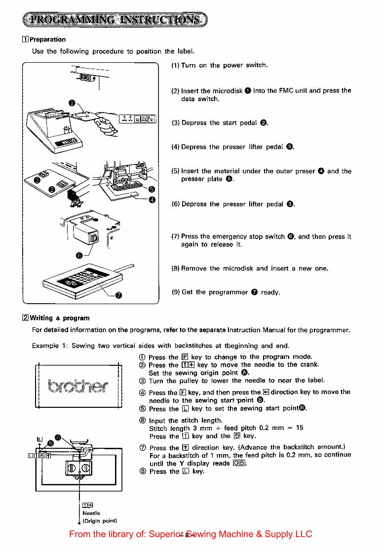
[I] Preparation
Use the following procedure to position the label.
[2]Writing a program
(1) Turn on the power switch.
(2) Insert the microdisk 0 into the FMC unit and press the data switch.
(3) Depress the start pedal $.
(4)-Depress the presser lifter pedal e.
(5) Insert the material under the outer preser 0 and the presser plate 0.
(6) Depress the presser lifter pedal e.
(7) Press the emergency stop switch C), and then press it again to release it.
(8) Remove the microdisk and insert a new one.
(9) Get the programmer 0 ready.
For detailed information on the programs, refer to the separate Instruction Manual for the programmer.
Example 1: Sewing two vertical sides with backstitches at tbeginning and end.
'rnl±l
1 Needle (Origin point)
<D Press the (f) key to change to the program mode. ® Press the [I]I±J key to move the needle to the crank.
Set the sewing origin point G. @ Turn the pulley to lower the needle to near the label.
@ Press the [E] key, and then press the 1B direction key to move the needle to the sewing start ~point 0.
® Press the [W key to set the sewing start point@).
® Input the stitch length. Stitch length 3 mm + feed pitch 0.2 mm = 15 Press the III key and the ~ key.
® Press the [!] direction key. (Advance the backstitch amount.) For a backstitch of 1 mm, the feed pitch is 0.2 mm, so continue until the Y display reads 10151.
® Press the [W key.
-8-From the library of: Superior Sewing Machine & Supply LLC
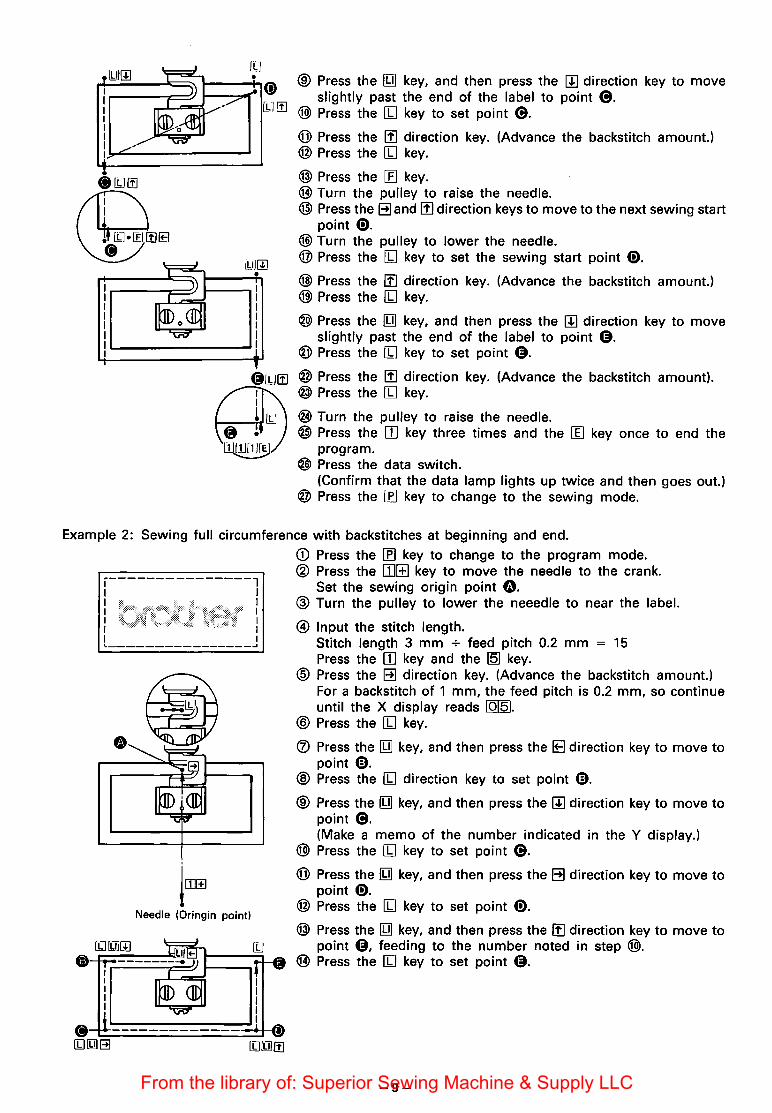
® Press the [Y] key, and then press the [!] direction key to move slightly past the end of the label to point e.
@) Press the III key to set point e. @ Press the [!] direction key. (Advance the backstitch amount.) @ Press the III key.
@ Press the [fJ key. @ Turn the pulley to raise the needle. @) Press the ~and[!] direction keys to move to the next sewing start
point 0. @) Turn the pulley to lower the needle. ®Press the III key to set the sewing start point 0. @ Press the [!] direction key. (Advance the backstitch amount.) @) Press the III key.
@) Press the [Y] key, and then press the [!] direction key to move slightly past the end of the label to point 4).
® Press the III key to set point 4).
0[1JI!J @ Press the [!] direction key. (Advance the backstitch amount). @ Press the III key.
@ Turn the pulley to raise the needle. @ Press the [I] key three times and the [I] key once to end the
program. @ Press the data switch.
(Confirm that the data lamp lights up twice and then goes out.) @ Press the IE] key to change to the sewing mode.
Example 2: Sewing full circumference with backstitches at beginning and end.
,---------------1 I I I I I I I I I I I I 1.----------------..J
lrnffi
Needle (Oringin point)
<D Press the If] key to change to the program mode. ® Press the III!±] key to move the needle to the crank.
Set the sewing origin point G. ® Turn the pulley to lower the neeedle to near the label.
@ Input the stitch length. Stitch length 3 mm + feed pitch 0.2 mm = 15 Press the III key and the 151 key.
@ Press the ~ direction key. (Advance the backstitch amount.) For a backstitch of 1 mm, the feed pitch is 0.2 mm, so continue until the X display reads 10151.
@ Press the III key.
® Press the [Y] key, and then press the IE direction key to move to point @).
® Press the III direction key to set point @).
® Press the [Y] key, and then press the [!] direction key to move to point e. (Make a memo of the number indicated in the Y display.)
@) Press the III key to set point e. @ Press the [Y] key, and then press the ~ direction key to move to
point 0. @ Press the III key to set point 0. @ Press the [Y] key, and then press the I!] direction key to move to
point 4), feeding to the number noted in step @). @ Press the III key to set point 4).
-9-From the library of: Superior Sewing Machine & Supply LLC

-----. I I I I
I I I I L _______________ j
@ Press the [Q] key, and then press the 1B direction key to move to the sewing end point.(Part way, turn the plley to raise the needle.)
@) Press the [1] key.
@ Press the ~ direction key. (Advance the backstitch amount. Continue until the X display reads 10151.
@ Press the [1] key.
@) Turn the pulley to raise the needle. @ Press the II] key three times and the ~ key once. ® Press the data switch.
(Confirm that the data lamp lights up twice and then goes out.) @ Press the (f] key to change to the sewing mode.
Example 3: Zigzag sewing on two sides
Zigzag width (I)
Pitch(P)S
I I I I I I .J.....____-t----_____,
Needle (Origin point)
[£)[!]~
<D Press the (f] key to change to the program mode. ® Press the [!] direction key to move the needle to the crank. ® Turn the pulley to lower the needle to near the lable. @ Input the zigzag width ([1JI1][[]).
Zigzag width (I) 3 mm + pitch (P) 3 mm - 1 = 0 * The zigzag width sewings to the left when facing the sewing
direction. Press the 171 key twice and the [Q] key once.
@ Press the [1] key to set the sewing origin point f). ® Press the [£] key, and then press the IB direction key to move the
needle to the sewing start point 0. 0 Press the [1] key to set the sewing start point 0. @ Input the stitch length.
Stitch length ·3 mm + feed pitch 0.2 mm = 15 Press the II] key and the 15] key.
® Press the IIJdirection key to move to the sewing end point (9. @) Press the [1] key to set point 8. @ Turn the pulley to raise the needle.
@ Press the [£] key. @) Press the[!] and~ direction keys to move to the next sewing start
point @). @ Turn the pulley to lower the needle. @ Press the [1] key to set the sewing ·start point @).
@) Press the 11IJ direction key to move to the sewing end point 8. @ Press the [1] key to set point 8. @ Turn the pulley to raise the needle. @) Press the II] key three times and the II] key once. ® Press the data switch.
(Confirm that the data lamp lights up twice and then goes out.) ® Press the If] key to change to the sewing mode.
-10-From the library of: Superior Sewing Machine & Supply LLC
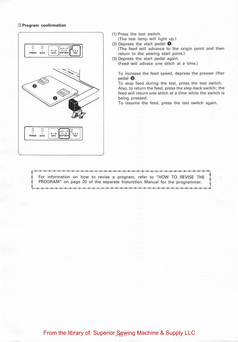
~Program confirmation
D D I I
POWER DATA
D D I I
POWER DATA
(1) Press the test switch. (The test lamp will l ight up.)
(2) Depress the start peda l 0 . (The feed will advance to the ong1n point and then return to the sewing start point.)
(3) Depress the start pedal again. (Feed wil l advace one stitch at a time.)
To increase the feed speed, depress the presser lifter pedal a. To stop feed during the test, press the test switch. Also, to return the feed, press the step-back switch; the feed wi ll return one stitch at a time while the switch is being pressed. To resume the feed, press t he test switch again.
?-------------------------------------~ ~ For information on how to revise a program, refer to "HOW TO REVISE THE t ~ PROGRAM" on page 20 of the separate lnsturction Manual for the programmer. ~
l-------------------------------------~
- 11 -From the library of: Superior Sewing Machine & Supply LLC

Make the adjustments while the machine is in the conditions indicated in steps CD through @ in the operation flowchart.
rn Presser plate lift (step CD)
Top of needle plate
/
(1) Close the air cock. (2) Loosen the nut 0 on the right cylinder and turn the piston shaft 8 to adjust so that the distance between
the bottom of the presser plate f) and the top of the needle plate is 21 mm.
121 Outer presser lift
Top of needle plate
(1) Close the air cock. (2) Loosen the nut 0 on the left cylinder and turn the piston shaft 8 to adjust so that the distance between
the bottom of the outer presser f) and the top of the needle plate is 21 mm.
1.31 Guide plate position (step ®)
II II
(1) Move the guide plate 0 left and right to adjust it so that it is centered beneath the presser plate f).
-12-From the library of: Superior Sewing Machine & Supply LLC

~Swing unit position (step @)
1. Lateral position
(1) Loosen screw 0. (2) Loosen screw f).
Turn the slide adjusting screw G to adjust the swing unit so that the label is centered over the guide plate e.
(3) Move the positioning guide 0 left and right so that the end of the guide is aligned with the hole in the positioning adjustment base 0.
2. Longitudinal position
(1) Loosen screw 0. (2) Loosen screw 0, and then turn screw 0 to adjust the swing unit so that the label is centered beneath
the presser plate 0. (3) Move the positioning adjustment base 0 back and forth so that surface® of the positioning guide 0 and
surface @ of the positioning adjustment base 0 are aligned.
151 Folding plate positions (steps ® and @))
11) Loosen screws 0 and adjust the folding plates so that the left and right clearances between the folding plates f) and the guide plate are each 1 to 2 mm. Also, loosen nut 8 and adjust bolt 0 so that the vertical clearance between the folding plates f) and the guide plate e is 0.5 to 1 mm.
(2) Loosen nut 0 and adjust bolt 0 so that the clearance between the folding plates f) and the material is 0,5 to 1 mm when the folding plates e and the presser plate 0 are lowered to the top of the material.
-13-From the library of: Superior Sewing Machine & Supply LLC

[Q] Cutter replacement
(1) Remeove the cutter cover 0 and the label presser @. (2) Loosen nut 0 and remove the cutter oepration lever 0. (3) Replace the cutters as a set.
[7] Switching to auto mode
[BJ Wiper position
~ Dip switches
O Standard operation (1) Depress the presser lifter pedal to lower the presser. (2) Depress the start pedal to beg in sewing.
<:g Changing the dip switch setting ~ (1) After first turning off the power switch, open the control
box. (2) Change the setting of the number 2 dip switch 0,
located at the lower left of the control circuit board.
O Operation after chang ing the dip switch setting (1) When the start pedal is depressed the presser will
descend and sewing w ill beg in.
(1) Adjust the solenoid lever f} so that the wiper 0 is slightly (approximately 1 0°) below horizontal at the stop position.
(2) Move the wiper 0 in and out so that when it operates the clearance between it and the tip of the needle is approximately 2 mm.
- 14 -From the library of: Superior Sewing Machine & Supply LLC

( OPERATION FLOWCHART )
( Start
Turn on the power switch.------~
Insert the microdisk. ---------~
Press the data switch.---------..~--- The data on the microdisk is input.
Depress the start pedai.---------J~foof--- Feed advances to the origin point and then returns to the sewing start point.
While pressing the test switch,-----..+-~~--- The label test mode beg ins. press the data switch aga in.
Subsequently, one operation is -----)+-11'----- G) The presser plate rises. performed each time the start pedal is depressed. @The guide p late moves forward.
~--@The swing unit moves toward the head.
~--@)The upper cutter moves upward and the rolle r turns.
* If the roll er continues to turn without stopping, insert a label beneath the sensor.
~---@The presser plate descends to the guide plate.
~--@The upper cutter cuts the label.
~--(f)The folding plates close and the swing unit returns to its original position.
~--@The folding plates close around the presser plate. (The label is fold ed.)
~--@The guide plate moves back.
~--@The presser plate and the fo lding plates descend.
~--@The folding p lates open.
~---@The fo lding plates rise.
Keep the presser lifter pedal depressed. The upper cutter rises and the roller turns.
Release the presser lifter pedal. The upper cutter cuts the label.
Press the emergency stop switch. The label test mode ends.
Press the emergency stop switch again. The em ergency stop switched is released.
( End
- 15 -From the library of: Superior Sewing Machine & Supply LLC