electromagnetism summary electrostatics charge...
TRANSCRIPT

ELECTROMAGNETISM SUMMARY
➤ Electrostatics
➤ Charge conservation
➤ Dielectrics
➤ Electromagnetic Shielding
1 ENGN4545/ENGN6545: Radiofrequency Engineering L#3

Electrostatics: The Case of Stationary Charge
➤ The source of all electromagnetic fields is ultimately the charge.➤ When there are no time variations, charge is the source of electric field.➤ For a point charge we have Coulomb’s law:
Er =q
4πǫ0r2
where the free space permittivity, ǫ0 = 8.85× 10⁻¹² Farads/m and q is inCoulombs.
2 ENGN4545/ENGN6545: Radiofrequency Engineering L#3

Electrostatics: The static electric field
➤ In general we have the following closed integral form (Gauss’s law):∮
A
E.dA =q
ǫ0
➤ Example: a charged capacitor. E = σ/ǫo...
3 ENGN4545/ENGN6545: Radiofrequency Engineering L#3
Electrostatics: The Electrostatic Potential
➤ Definition: The potential difference between two points x1 and x2 is givenby,
Φ = −
x2∫
x1
E.dl = −
∫
γ
E.dl
➤ Since the path γ can be any which connects the points x1 and x2 we mayconclude that E = −∇Φ.
➤ Kirchhoffs voltage law.
4 ENGN4545/ENGN6545: Radiofrequency Engineering L#3

Charge Conservation
➤ When current flows out of a region in space, it depletes the charge in thatregion. The current per unit area j is given by,
I =
∮
A
j.dA = −∂q
∂t
where the current I is, I =∫A
j.dA for any surface (not necessarily closed).
➤ If q is in Coulombs and the time in seconds then I is in Amperes .➤ A general law... not just electrostatics.➤ If current flows round in a closed loop, then there need be no change in the
charge: Kirchhoffs current law.➤ Quite generally: j = nqv where n is the charge carrier density, q their
charge and v their velocity.
5 ENGN4545/ENGN6545: Radiofrequency Engineering L#3

Dielectrics and Conductors
➤ Dielectrics are insulating materials that do not allow D.C. current to flowthrough them. Usually we just call them insulators.
➤ In conductors, charge carriers (electrons) are free to move. E.G. metals.
➤ We study briefly the phenomenology of dielectrics and conductors.
6 ENGN4545/ENGN6545: Radiofrequency Engineering L#3

Dielectrics 1
➤ Dielectrics are insulating materials that do not allow D.C. current to flowthrough them.
➤ Electrons and nuclei in the atoms and molecules of dielectrics experienceopposing forces in the presence of an imposed electric field.
➤ Electrons move opposite to the field and nuclei move in the direction of thefield. This separation of charge produces a polarisation .
➤ The charge separation induced by the field, acts to reduce the electric fieldwithin the dielectric.
7 ENGN4545/ENGN6545: Radiofrequency Engineering L#3

Dielectrics 2: Polarisation
➤ Polarisation P is the dipole moment per unit volume induced by animposed, external electric field
➤ P = nqd, where n is the number density of dipoles, q is the charge ateach end of the dipole and d is the displacement of the ±q charges at eachend of the dipole.
➤ Polarisation is a vector quantity.➤ Pictorial representation of a dipole moment:
8 ENGN4545/ENGN6545: Radiofrequency Engineering L#3

Dielectrics 3: Polarisation
➤ At the edge of a polarised dielectric there is a charge density left over bythe displacement of the dipoles.
➤ The surface charge density on the dielectric σp = P.n̂ where n̂ is unitvector normal to the surface.
➤ Notice that σp belongs to the material. It is not a free charge.
9 ENGN4545/ENGN6545: Radiofrequency Engineering L#3

Dielectrics 4: Relative dielectric constant
➤ The relative dielectric constant ǫr is defined by,
P = ǫ0(ǫr − 1)E
➤ The Electric Displacement D is defined by,
D = ǫ0E + P = ǫrǫ0E
➤ Main advantage of the definition of D is that its source is the free chargeonly and not the induced polarisation charge,∮
A
D.dA = qfree
➤ c.f. ∮
A
E.dA =qtotal
ǫ0
10 ENGN4545/ENGN6545: Radiofrequency Engineering L#3

Dielectrics 5: Key Points
➤ The relative dielectric constant ǫr describes the behaviour of a dielectricwhen exposed to an oscillating electric field.
➤ ǫr at D.C. is a positive dimensionless number and ǫr > 1 for dielectrics.
➤ When the electric field oscillates, ǫr is a complex function of frequency.
➤ The ratio of the imaginary to real components of ǫr is termed the losstangent of the dielectric:
tanδ =Im(ǫr)
Re(ǫr)
11 ENGN4545/ENGN6545: Radiofrequency Engineering L#3

Conductors and Ohm’s law
➤ Ohm’s law: The current density in a conductor is proportional to the electricfield within the conductor.
j = σE
where σ is the conductivity.➤ Conductors are completely specified by σ.➤ For copper, σ = 5.80 × 10⁷mhos/meter..➤ Ohm’s law is assumed to be an accurate result for metals at all
radiofrequencies :).➤ I.E. σ is always a real number and independent of frequency.
12 ENGN4545/ENGN6545: Radiofrequency Engineering L#3

Conductors vs Dielectrics?
➤ For metals: j = σE
➤ For dielectrics: P = ǫ0(ǫr − 1)E
➤ If P oscillates as a function of time then,
jωP = jωǫ0(ǫr − 1)E
➤ Since the dipoles are reversing sign at rate ω while traversing a distance d
we may write, jP = jωP, where jP is the polarisation current.➤ Thus dielectrics obey a sort of Ohm’s law with jP = σPE and
σP = jωǫ0(ǫr − 1)
➤ The main difference between conductors and insulators is simply that σ isresistive for a conductor, but is mainly reactive for insulators.
➤ In fact, generally speaking, ǫr is a complex function of frequency.
13 ENGN4545/ENGN6545: Radiofrequency Engineering L#3

Electromagnetic Shielding 1
➤ Ohm’s law for metals and Gauss’s law for the electric field give rise to theconcept of electromagnetic shielding
14 ENGN4545/ENGN6545: Radiofrequency Engineering L#3

Electromagnetic Shielding 2: The Floating Conducting Box
Suppose that there is an isolated positive charge, q, in a cavity and that theconducting box is floating (not connected to earth) and neutral (has no netcharge).
15 ENGN4545/ENGN6545: Radiofrequency Engineering L#3

Electromagnetic Shielding 3: The Floating Conducting Box
We can deduce the following...
➤ Electric current is finite (actually zero here) and Ohm’s law implies that theelectric field inside the conductor (Turquoise region) is zero .
➤ Gauss’s law implies that the net negative charge on the inside of the innerwall of the cavity is equal and opposite in sign to q.
➤ Charge conservation implies that the amount of positive charge on theouter surface equals the negative charge on the inner surface.
16 ENGN4545/ENGN6545: Radiofrequency Engineering L#3
Electromagnetic Shielding 4: The Floating Conducting Box
Observations:(a) The negative charge arranges itself to give perfect cancellation of the
electric field inside the conductor.
(b) The negative surface charge density (σ) is highest on the wall closest to q.
(c) The positive charges on the outer surface see no electric field inside theconductor and therefore do not respond to movement in either q or thenegative charge on the cavity wall.
(d) The positive charges on the outside bunch toward surfaces of highcurvature and spread out along surfaces of low curvature.
17 ENGN4545/ENGN6545: Radiofrequency Engineering L#3

Electromagnetic Shielding 5: The Floating Conducting Box
(e) The charge on the surface of the metal-air interface lies right on thesurface and not inside the conductor. (RF burns?)
(f) By Gauus’s law, here is still an electric field outside the conductor.
(g) If there were no net charge inside the cavity (q = 0) then there would beno electric field outside the conducting box either . For example therecould even be a +q and a −q arbitrarily located. It makes no difference.
(h) At the surface of the metal, the electric field vector is always normal. Thereis never any tangential component of electric field on the surface of aconductor.
18 ENGN4545/ENGN6545: Radiofrequency Engineering L#3

Electromagnetic Shielding 6: The Earthed Conducting Box
➤ Largely the same observations as for the floating case, except that nowthere is no field outside the conductor under any condition.
➤ Main practical conclusion: Closed conducting boxes isolate the outsideworld from electromagnetic influences within the box and vic e versa.
19 ENGN4545/ENGN6545: Radiofrequency Engineering L#3

Electromagnetic Shielding 7: Proximity to a Conductor
➤ A charge near a conducting surface attracts charge of the opposite sign tothe nearest point on the surface.
➤ These surface charges arrange themselves so that the tangntialcomponent of electric field is zero on the surface.
➤ One may compute the electric field outside the conductor by assuming(mathematically) that there is an image charge within the conductor.
20 ENGN4545/ENGN6545: Radiofrequency Engineering L#3
Electromagnetic Shielding 8: Proximity to Floating Conduc tors
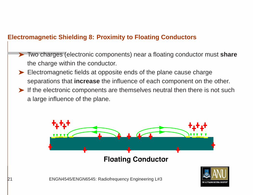
➤ Two charges (electronic components) near a floating conductor must sharethe charge within the conductor.
➤ Electromagnetic fields at opposite ends of the plane cause chargeseparations that increase the influence of each component on the other.
➤ If the electronic components are themselves neutral then there is not sucha large influence of the plane.
21 ENGN4545/ENGN6545: Radiofrequency Engineering L#3

Electromagnetic Shielding 9: Proximity to Earthed Conduct ors
➤ Earth is an inexhaustible source of charge.
➤ Two charges (electronic components) near an earthed conductor attractcharge from earth.
➤ Electromagnetic fields at opposite ends of the plane cause chargeseparations that decrease the influence of each component on the other.
22 ENGN4545/ENGN6545: Radiofrequency Engineering L#3