electromagnetic field transformations for measurements and ... · electromagnetic field...
TRANSCRIPT

Progress In Electromagnetics Research, Vol. 151, 127–150, 2015
Electromagnetic Field Transformations for Measurementsand Simulations
Thomas F. Eibert*, Emre Kılıc, Carlos Lopez, Raimund A. M. Mauermayer,Ole Neitz, and Georg Schnattinger
(Invited Paper)
Abstract—Electromagnetic field transformations are important for electromagnetic simulations andfor measurements. Especially for field measurements, the influence of the measurement probe must beconsidered, and this can be achieved by working with weighted field transformations. This paper is areview paper on weighted field transformations, where new information on algorithmic properties andnew results are also included. Starting from the spatial domain weighted radiation integral involvingfree space Green’s functions, properties such as uniqueness and the meaning of the weighting functionare discussed. Several spectral domain formulations of the weighted field transformation integralsare reviewed. The focus of the paper is on hierarchical multilevel representations of irregular fieldtransformations with propagating plane waves on the Ewald sphere. The resulting Fast IrregularAntenna Field Transformation Algorithm (FIAFTA) is a versatile and efficient transformation techniquefor arbitrary antenna and scattering fields. The fields can be sampled at arbitrary irregular locationsand with arbitrary measurement probes without compromising the accuracy and the efficiency ofthe algorithm. FIAFTA supports different equivalent sources representations of the radiation orscattering object: 1) equivalent surface current densities discretized on triangular meshes, 2) planewave representations, 3) spherical harmonics representations. The current densities provide for excellentspatial localization and deliver most diagnostics information about the test object. A priori informationabout the test object can easily be incorporated, too. Using plane wave and spherical harmonicsrepresentations, the spatial localization is not as good as with spatial current densities, but still muchbetter than in the case of conventional modal expansions. Both far-field based expansions lead tofaster transformations than the equivalent currents and in particular the orthogonal spherical harmonicsexpansion is a very attractive and robust choice. All three expansions are well-suited for efficient echosuppression by spatial filtering. Various new field transformation and new computational performanceresults are shown in order to illustrate some capabilities of the algorithm.
1. INTRODUCTION
Maxwell’s equations have been presented at about 150 years ago [1]. Since that time, the views onelectromagnetic fields and the governing equations have been changing and many techniques for thesolution of the field equations have been investigated. Nowadays, we concentrate mostly on differentialequation based field solutions and on integral representations of the fields due to sources or equivalentsources [2–4]. Integral representations calculate the fields by integrals over the sources together withan analytically known kernel, the Green’s function, which is, however, only known for free space or
Received 11 December 2014, Accepted 15 May 2015, Scheduled 18 May 2015Invited paper for the Commemorative Collection on the 150-Year Anniversary of Maxwell’s Equations.
* Corresponding author: Thomas F. Eibert ([email protected]).The authors are with the Lehrstuhl fur Hochfrequenztechnik, TU Munchen, Munich 80290, Germany.

128 Eibert et al.
other canonical solution domains. In this paper, we consider integral representations involving Green’sfunctions of free space, which are called field transformations, since the sources are mostly equivalentsources, which are linked to the fields, typically on a Huygens surface. The integral representations areextended by weighting or reaction integrals in order to have access to true field observations by realisticmeasurement probes, where the influence of the probes is considered by appropriate weighting functions.Moreover, the weighting integral formulation gives access to reaction and reciprocity considerations [2, 5–7] as frequently used in numerical techniques such as the Method of Moments (MoM) [8]. Even thoughthe Green’s functions are known analytically, the field transformation and weighting integrals mustusually be evaluated numerically. Since the transformations are four to six fold integrals, their numericalsolution becomes easily computationally intensive and efficient methods are required to evaluate the fieldtransformations. Another issue with the numerical evaluation of these integrals are the singularities ofthe involved Green’s functions for closely located source and observation points. The accurate evaluationof these singularities is essential for integral equation solutions of radiation and scattering problems,where the radiation integrals must be evaluated in the locations of the equivalent sources in orderto enforce the boundary conditions on the radiation or scattering objects [4, 8, 9]. A wide variety ofsingularity treatments is nowadays available, e.g., see [10, 11], where such techniques are, however,not in the focus of this paper. The focus are field transformations, where weighted field observationsare known from measurements or simulations and where equivalent sources reproducing these fieldobservations shall be computed. Since observation and source locations are typically well separated,particular singularity treatment is here not necessary, unless the field transformations are combined withadditional constraints such as a null-field condition in order to obtain Love equivalent surface currentdensities [12–15]. Once the equivalent sources have been determined, they shall be used to computefurther field observations of interest, e.g., the far-field of an antenna or a scatterer. Especially antennafield measurements have become more and more important over the past years, since the accurateknowledge of the radiation behavior of antennas is essential to further improve the performance andcapabilities of wireless communication and sensor systems. Full knowledge about the radiation or thescattering behavior of an object is obtained by field measurements on a closed surface around the objectand by measuring the amplitudes and the phases of the fields. Closed measurement surfaces can bereplaced by open ones, if it is clear that the field amplitudes are very low in some region of space orif interest is only in certain radiation directions. Also, phaseless measurements are possible, where therobustness of the transformations is, however, reduced and an increased number of measurement samplesshould be collected [16–19]. Once appropriate measurements have been taken, field transformations canbe utilized to compute the radiation or scattering fields of a Device Under Test (DUT) in any locationoutside the sources of the DUT and it is even possible to perform DUT diagnostics by evaluating thefields very close to the DUT.
Classical antenna field transformation methods work with modal expansions of the fields, wherethe advantageous orthogonality of the field modes is utilized for measurements performed on canonicalsurfaces such as planes, cylinder shells, or spheres. It is also very common to accelerate the computationof the modal expansion coefficients by utilizing the Fast Fourier Transformation (FFT). This leads,however, to the requirement that the measurement samples must be placed regularly, see, e.g., [20] foran overview of modal field transformation techniques. Due to this, the flexibility and the diagnosticscapabilities of the conventional antenna field transformation techniques are rather limited and quiteoften considerably more measurement samples have to be collected than actually required. Anothershortcoming of the modal field transformations is that they cannot consider a priori information aboutthe spatial sources distribution of the DUT, except for limiting the number of modes.
Inverse equivalent current or sources reconstruction methods [12, 21–23] work with spatiallydiscretized equivalent sources representations of the DUT. However, the basic equivalent sourcesmethods with spatial integral representation are computationally very demanding, as mentioned before,and their speed-up by fast integral operator evaluation methods is more or less mandatory to transformthe measurements of electrically large DUTs. In [24], regularly sampled planar measurements have beentransformed with FFT acceleration. The most flexible and useful fast integral operator computationmethod for this purpose is the Multilevel Fast Multipole Method (MLFMM) [9, 25], which has beenadapted in [22, 23] for the solution of inverse equivalent current problems. A single-level FMM hasbeen used in [26]. In contrast to the utilization of MLFMM for the solution of integral equations

Progress In Electromagnetics Research, Vol. 151, 2015 129
related to radiation and scattering problems, the challenges in its use for field transformations andinverse equivalent current problems are the often relatively large separation distance between sourcesand observation locations, the relatively large spatial separation between different observation locations,and the appropriate treatment of realistic measurement probes.
With the MLFMM formulation for inverse equivalent current problems, it became obvious that therepresentation with propagating plane waves on the Ewald sphere, opens up completely new possibilitiesfor performing near-field far-field (NFFF) transformations. The key is that the introduced discretizedplane wave spectra can directly be utilized as equivalent sources representing the DUT [27, 28].This resulted in a very efficient algorithm, which we call FIAFTA (Fast Irregular Antenna FieldTransformation Algorithm). FIAFTA is able to include the influence of arbitrary measurement probesjust by their 3D FF patterns and it offers several possibilities to represent the equivalent sources of theDUT. For instance, in antenna diagnostics, equivalent surface currents on a triangular mesh are useful.The triangular mesh can directly model the enveloping surface of the antenna and the surface currentdensities can be linked to the radiation fields near the antenna. The plane wave expansion coefficientsof a source group according to the MLFMM hierarchy can also be used as unknowns for the inverseproblem instead of the expansion coefficients of the surface currents on a triangular mesh. For furtherreduction of memory consumption and most robust behavior, the plane wave spectrum of a source boxcan be expanded in orthogonal spherical harmonics whose coefficients are used as unknowns. For theseequivalent sources representations, the hierarchical octree structure of the MLFMM helps to localizethe sources. Only boxes need to be defined as source boxes, which contain parts of a Huygens surfacerepresenting the DUT. A priori knowledge about the device geometry can easily be incorporated intothe model for the inverse problem solution for all types of sources.
The ability to position sources arbitrarily within the octree makes it possible to place sources atlocations where parasitic echo centers due to scattering objects are assumed during the NF measurement.By spatial filtering of these sources, DUT fields such as the far-field can be computed only from thesubset of equivalent sources belonging to the DUT. The influence of the disturbing sources on themeasurements is thereby eliminated.
The outline of the paper is as follows. In Section 2, electromagnetic field transformations inform of weighted spatial radiation integrals are introduced and discussed together with uniquenessand complexity considerations. Spectral representations of the field transformation operator are thenreviewed in Section 3, where first planar plane wave expansions are discussed, which have a seriesof unique properties, but whose applicability is restricted to field observations in a plane. Sphericalwave expansions are shortly reviewed in order to emphasize its beauty and importance for practicalNF antenna measurements. The central part of this section are, however, propagating plane waveexpansions on the Ewald sphere. In Section 4, multilevel hierarchical field decompositions are reviewedand discussed, which are the basis of FMM and MLFMM as well as of FIAFTA. These techniquescombine the ideas of the before discussed plane wave and spherical harmonics expansions in order toachieve high flexibility and efficieny at the same time. Section 5 concentrates on FIAFTA. Startingfrom the inverse problem solution concept, the various available sources representations and modellingcapabilities are discussed. Finally, Section 6 shows various results obtained by FIAFTA in order todemonstrate its capabilities.
As already mentioned, the paper is mostly a review paper, but the presented transformationand computational performance results are new. Also, many new insights into the algorithmsare included. Further capabilities of FIAFTA including the efficient treatment of non-redundantmeasurements [29, 30], echo suppression techniques by inward and outward looking measurementprobes [31], volumetric imaging by hierarchical disaggregation of broadband field observations [32],efficient transformation of phaseless field measurements with first results [18, 19], and the utilizationof FIAFTA within non-linear inverse material problem solutions [14, 15, 33] are found in the givenreferences. Extensive error investigations are presented in [34]. Recently, the FIAFTA concept wasextended for the NFFF transformation of monostatic radar cross section measurements [35]. A portableantenna measurement system, which can fully benefit from the great transformation flexibility ofFIAFTA, has been presented in [36].

130 Eibert et al.
sV
J
M
AJ
AM
x
yz r
r' 1V
2V
1S
2S
mU(r )
n
n
Figure 1. Field transformation configuration: sources J and M within Vs bound by the Huygenssurface S1 generate fields which are observed by probe antennas at measurement locations rm. Theradiated fields outside of S1 can also be generated by equivalent surface current densities JA and MA
on the surface S1. The fields in V1 and V2 can be determined in a unique way from two independentfield observations on the surface S2.
2. FORMULATION OF WEIGHTED FIELD TRANSFORMATIONS
The considered linear field transformations are integrals of the form
U (rm) =∫∫∫Vw
w (r− rm) ·∫∫∫
Vs
[GE
J
(r, r′
) · J (r′
)+ GE
M
(r, r′
) ·M (r′
)]dv′dv , (1)
for time harmonic fields and sources with a suppressed time factor ejωt dependent on the angularfrequency ω. The transformation configuration is illustrated in Fig. 1 and as usual, r′ denotes sourcelocations, r observation locations, and w is a vector weighting function, which produces a fieldobservation in form of the voltage U † at the location rm. J and M are the electric and magneticsource current densities and GE
J and GEM are the corresponding dyadic Green’s functions, respectively,
which are known analytically, as, e.g., for free space in the form of
GEJ (r, r′) = −j
ωμ
4π
(I +
1k2
∇∇)
e−jk|r−r′|
|r − r′| , GEM (r, r′) = − 1
4π∇× I
e−jk|r−r′|
|r − r′| . (2)
k is here the wavenumber of free space, μ the permeability of free space, and I the unit dyad.In many cases, it is useful to work with surface current densities JA and MA as well as with surface
weighting functions wA defined in locations rA on surfaces, which are linked to the corresponding volumedensities via
J (r) = JA (r) δ (r− rA) , M (r) = MA (r) δ (r − rA) , w (r) = wA (r) δ (r − rA) . (3)
Based on Huygens principle, the surface current densities can be related to the tangential fields by
JA (r) = n × H (r) , MA (r) = −n × E (r) , (4)
where n is the unit normal vector on an appropriate Huygens surface. If the equivalent surface currentsor the tangential fields are known on closed Huygens surfaces or if open surfaces can be closed bysurface extensions with vanishing tangential fields, Huygens and equivalence principles can be usedfor the derivation of uniqueness statements of the transformed fields or observables according to (1).Important for this to be valid is that the field transformations are only performed in source free regions.For the case in Fig. 1, it is, e.g., required that the relevant primary sources J and M are confined to† U can be an open-circuit voltage or the voltage at a certain load impedance.

Progress In Electromagnetics Research, Vol. 151, 2015 131
the region Vs‡. With knowledge of the equivalent surface currents on one of the surfaces S1 or S2 in
Fig. 1, the electromagnetic fields are uniquely defined anywhere in space (in V1 and in V2) except for thevolume Vs with the original sources. In case of radiation problems, the primary sources are containedin Vs, whereas for scattering problems, it is assumed that the sources of the scattered fields are confinedto Vs and that these sources are induced by an incident field. (1) relates then to the scattered fields.
In NF measurements, the complex fields (amplitude and phase) are usually measured on the surfaceS2 (utilizing appropriate measurement probes) and equivalent sources within Vs or on S1 are determinedfrom these measurements in order to reproduce the measurements. Then, the found equivalent sourcesare used to compute the far-fields or near-fields anywhere in V1 and V2. The determination of theequivalent sources within Vs or on S1 is a linear inverse problem solution with a forward operator in theform of (1). The inverse problem solution is in particular necessary in order to remove the influence ofthe measurement probe antennas represented by the weighting function w in (1).
For the transformation of simulated near-fields, an inverse problem solution is usually not required,since the fields are directly accessible without a measurement probe. Consequently, any observationfield in V1 or V2 can be computed directly from the also known equivalent sources JA and MA on S1
by evaluating (1) in the form of a forward operator.According to the uniqueness theorem, it is known that the knowledge of one type of tangential
surface fields (electric or magnetic) is sufficient to uniquely define the electromagnetic fields in thewhole volume enclosed by the surface as long as no resonances occur. In field transformations as, e.g.,for measurements of radiation or scattering fields, it is commonly assumed that resonances cannot occurand, therefore, only one type of measurement (with a certain measurement probe) is usually performed§.Also, it is noted that one type of equivalent surface currents, e.g., on S1 in Fig. 1, is sufficient to reproduceany field in V1 or V2, even though the surface current densities and the corresponding fields do no longerfulfill (4) in this case. If both types of surface current densities are present during the inverse solutionprocess, they are not uniquely defined anymore and they can contain non-radiating currents. These non-radiating currents are not harmful to the field transformation in most cases, but they can be suppressedby further constraint equations forcing the fields inside Vs to be zero, if required. In this case, JA andMA are unique and fulfill (4) [12, 14, 15].
In real field measurements, the weighting function w represents the measurement probe and onemay ask what the physical meaning of w is. The question can be resolved by looking at differentequivalent reciprocity interaction integral representations for the probe antenna. Fig. 2(a) illustrates apossible measurement probe, where U is the receive voltage for a given incident field and I is the feedcurrent of the probe antenna in transmit mode, which is impressed in the terminal region. Fig. 2(b)shows an equivalent representation of the same antenna, where the antenna structure has been replacedby an equivalent electric current distribution impressed within the probe volume Vw. By invoking theequivalence principle [2], it can be shown that both configurations radiate the same fields in transmitmode‖. Together with the reciprocity theorem [2], it can then be shown that
U(rm)I(rm) =∫∫∫Vw
E(r) · I(rm)w(r − rm)dv −→ U(rm) =∫∫∫Vw
E(r) · w (r − rm) dv. (5)
Consequently, the probe weighting function w can be any equivalent current density impressed in freespace representing the probe radiation in transmit mode for a feed current of 1A at the terminals ofthe antenna.
In any numerical evaluation of (1) or of the corresponding inverse problem, the sources arediscretized by a finite set of basis functions and a finite number of observations are considered. Due tothe global nature of the forward operator (1), its direct evaluation will cause a numerical complexity ofO(MN), if M is the number of measurement samples and N the number of basis functions representingthe sources. Since this quadratic complexity (assuming M = N) will quickly lead to unacceptablecomputation times for large problems, it is mandatory that efficient numerical methods are constructedfor the representation of (1) or its inverse.‡ Please note that these primary sources can be due to the DUT, but also due to undesired echo contributions.§ As discussed in [31], measurements with different types of probes, e.g., inward and outward looking, can be used to distinguishbetween sources within and outside of the measurement surface (S2 in Fig. 1)‖ For this, it is assumed that mutual interactions involving the probe antenna are negligible.

132 Eibert et al.
mU(r ) mI(r )
m mJ(r-r )=I(r )w(r-r )
mU(r ) mI(r )
E(r)
m
(a) (b)
Figure 2. (a) Probe antenna with transmit feed current and receive voltage. (b) Equivalent probemodel with removed antenna structure and impressed transmit electric current density in free space.
3. SPECTRAL REPRESENTATIONS OF THE FIELD TRANSFORMATIONS
The key for an efficient evaluation of the forward operator (1) is to eliminate its inherent redundancy.This redundancy is due to the fact that the waves generated by sources in a certain volume can berepresented by a limited number of degrees of freedom dependent on the required accuracy. To achieve aredundancy reduction, the waves radiated by the sources are expanded into a set of linearly independentwave objects, which are often solutions of Maxwell’s equations and which are orthogonal with respect toeach other. Similarly, the weighting functions w in (1) are only sensitive to a limited number of degreesof freedom of the incident wave field. This fact can be used for a further redundancy reduction byexpanding the receive fields at the location of a weighting function into appropriate wave field objects.Since the wave field objects for the expansion of radiated fields are usually outgoing waves and theoptimal expansion fields around the weighting functions or receivers are incident waves, translationoperators may additionally be needed to convert the outgoing wave expansions into incident waveexpansions. The efficiency of these translations is also very important for the overall efficiency, whichcan be achieved for the evaluation of (1) or for the corresponding inverse problem solution.
3.1. Planar Plane Wave Expansion
One of the simplest wave expansions is found by expanding the fields or equivalently the pertinentGreen’s functions in (2) in a plane of infinite extent into plane waves. Formally, the Sommerfeldidentity [2]
14π
e−jk|r−r′|
|r− r′| =
+∞∫∫−∞
e−jkz|z−z′|
kze−jkx(x−x′)e−jky(y−y′)dkxdky (6)
with kz =√
k2 − k2x − k2
y can be used to achieve this, where the field expansion is here performed in aplane z = const.. Assuming only electric current sources and that all sources are below the expansionplane with all observation locations above the expansion plane, (1) together with the Sommerfeldidentity (6) can be written in form of
U (rm) = −jωμ
+∞∫∫−∞
[w(kx, ky)e−jkz(zm−z′s) · J(kx, ky)
]ejkxxmejkyymdkxdky (7)
with
J(kx, ky) =∫∫∫
Vs
[1kz
(I +
1k2
∇′∇′)
ejkxx′ejkyy′
ejkz(z′−z′s)]· J (
r′)
dv′ (8)
andw(kx, ky) =
∫∫∫Vw
w (r− rm) e−jkx(x−xm)e−jky(y−ym)e−jkz(z−zm) dv. (9)

Progress In Electromagnetics Research, Vol. 151, 2015 133
It is obvious that J and w are the Fourier or inverse Fourier transforms of the source currents andthe weighting or receiving function, respectively, which are related to the corresponding FF patterns asknown from antenna theory. z′s is here chosen as a reference z-location for the sources Fourier transform.The weighting function Fourier transform is defined with respect to a local coordinate system with itsorigin located in the measurement location rm and is, therefore, independent from rm. Writing thereceived signal as a Fourier integral
U (rm) =
+∞∫∫−∞
U(kx, ky)ejkxxmejkyymdkxdky (10)
and by utilizing the orthogonality of the exponentials with respect to kx and ky, we obtain
U(kx, ky) = w(kx, ky)e−jkz(zm−z′s) · J(kx, ky), (11)where the plane wave expansion of the received signal is usually obtained by regularly sampling thereceive field with a given measurement probe with fixed orientation within a measurement plane. Inthis case, the plane wave expansion in (10) can be efficiently obtained by FFT. In planar antennameasurements, the receive signals U(rm) are measured with a measurement probe, U is computed byFFT and the algebraic Equation (11) is inverted to obtain J. Usually, two linearly independent (possiblyorthogonal) measurement probes are used in order to find the relevant vector components of J. Once Jhas been determined, the far-field is found from [20]
EFF (ϑ,ϕ) = kωμ cos(ϑ)e−jkr
2πrJ (k sin(ϑ) cos(ϕ), k sin(ϑ) sin(ϕ)) . (12)
An important advantage of the planar plane wave expansion is that radiated wave objects are identicalto incident wave objects, i.e., both are just plane waves. As seen in (7), only a phase shift is needed totranslate the radiated waves into incident waves at the observation locations. Since every radiated waveis directly translated into just one incident wave, this translation operator is called diagonal. Writingit in matrix form, it is different from zero only on the main diagonal.
An interesting property of the planar plane wave expansion is the strict separation of propagatingand evanescent waves with respect to the expansion plane. Since the evanescent waves do not transportenergy from the sources to the observation probes in antenna measurements¶, they can be completelyomitted in antenna field transformations. This separation of evanescent and propagating waves can alsobe considered as a reason for the fact that supergain effects of antennas are usually only observed inendfire and frontfire directions, but not at broadside.
Practical NF measurements and numerical evaluations of the field transformations require adiscretization of the plane wave spectra, where it is commonly accepted that sample spacings of halfa wavelength λ are required in planar NF measurements [20]. This is, however, only the case, if FFTbased field transformations are utilized, which are not able to consider any a priori knowledge about theDUT. If the knowledge about the shape of the DUT is considered and more flexible field transformationapproaches are employed, reduced sampling rates can be achieved for many configurations [29, 30, 37–39].
More information on planar NF measurements and the corresponding FFT based NFFFtransformations can, e.g., be found in [20, 40].
3.2. Spherical Wave Expansion
Spherical wave expansions are based on electromagnetic eigenmodes in spherical coordinate systems.Similar to (6), the scalar Green’s function can be expanded in form of [2]
14π
e−jk|r−r′|
|r − r′| = −jk
∞∑n=1
n∑m=−n
jn(kr′)h(2)n (kr)Y∗
nm(ϑ′, ϕ′)Ynm(ϑ,ϕ) (13)
where the radiating wave expansion with respect to r consists now of outgoing spherical waves containingthe spherical Hankel functions h(2)
n of 2nd kind and order n together with the spherical harmonics Ynm.¶ This is true as long as mutual coupling between the sources and the probes is neglected, what is a common assumption in antennaand scattering measurements.
134 Eibert et al.
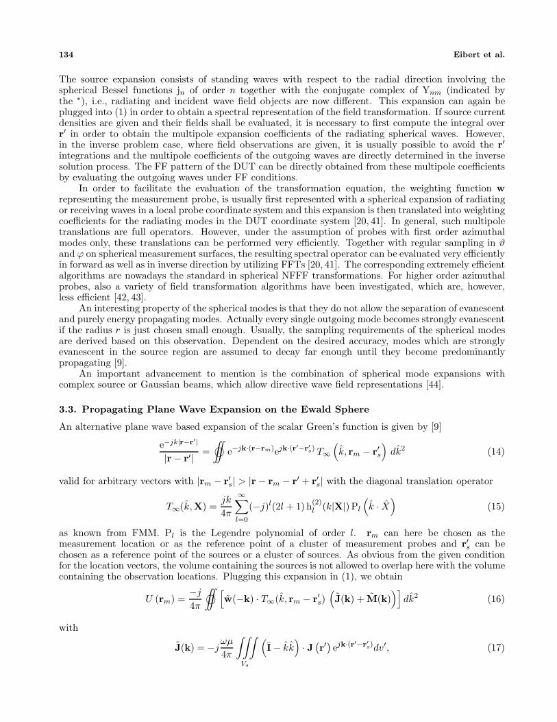
The source expansion consists of standing waves with respect to the radial direction involving thespherical Bessel functions jn of order n together with the conjugate complex of Ynm (indicated bythe ∗), i.e., radiating and incident wave field objects are now different. This expansion can again beplugged into (1) in order to obtain a spectral representation of the field transformation. If source currentdensities are given and their fields shall be evaluated, it is necessary to first compute the integral overr′ in order to obtain the multipole expansion coefficients of the radiating spherical waves. However,in the inverse problem case, where field observations are given, it is usually possible to avoid the r′integrations and the multipole coefficients of the outgoing waves are directly determined in the inversesolution process. The FF pattern of the DUT can be directly obtained from these multipole coefficientsby evaluating the outgoing waves under FF conditions.
In order to facilitate the evaluation of the transformation equation, the weighting function wrepresenting the measurement probe, is usually first represented with a spherical expansion of radiatingor receiving waves in a local probe coordinate system and this expansion is then translated into weightingcoefficients for the radiating modes in the DUT coordinate system [20, 41]. In general, such multipoletranslations are full operators. However, under the assumption of probes with first order azimuthalmodes only, these translations can be performed very efficiently. Together with regular sampling in ϑand ϕ on spherical measurement surfaces, the resulting spectral operator can be evaluated very efficientlyin forward as well as in inverse direction by utilizing FFTs [20, 41]. The corresponding extremely efficientalgorithms are nowadays the standard in spherical NFFF transformations. For higher order azimuthalprobes, also a variety of field transformation algorithms have been investigated, which are, however,less efficient [42, 43].
An interesting property of the spherical modes is that they do not allow the separation of evanescentand purely energy propagating modes. Actually every single outgoing mode becomes strongly evanescentif the radius r is just chosen small enough. Usually, the sampling requirements of the spherical modesare derived based on this observation. Dependent on the desired accuracy, modes which are stronglyevanescent in the source region are assumed to decay far enough until they become predominantlypropagating [9].
An important advancement to mention is the combination of spherical mode expansions withcomplex source or Gaussian beams, which allow directive wave field representations [44].
3.3. Propagating Plane Wave Expansion on the Ewald Sphere
An alternative plane wave based expansion of the scalar Green’s function is given by [9]
e−jk|r−r′|
|r− r′| =∫©∫
e−jk·(r−rm)ejk·(r′−r′s) T∞(k, rm − r′s
)dk2 (14)
valid for arbitrary vectors with |rm − r′s| > |r − rm − r′ + r′s| with the diagonal translation operator
T∞(k,X) =jk
4π
∞∑l=0
(−j)l(2l + 1) h(2)l (k|X|) Pl
(k · X
)(15)
as known from FMM. Pl is the Legendre polynomial of order l. rm can here be chosen as themeasurement location or as the reference point of a cluster of measurement probes and r′s can bechosen as a reference point of the sources or a cluster of sources. As obvious from the given conditionfor the location vectors, the volume containing the sources is not allowed to overlap here with the volumecontaining the observation locations. Plugging this expansion in (1), we obtain
U (rm) =−j
4π
∫©∫ [
w(−k) · T∞(k, rm − r′s)(J(k) + M(k)
)]dk2 (16)
with
J(k) = −jωμ
4π
∫∫∫Vs
(I − kk
)· J (
r′)ejk·(r′−r′s)dv′, (17)

Progress In Electromagnetics Research, Vol. 151, 2015 135
M(k) = jk
4π
∫∫∫Vs
(k × M
(r′
))ejk·(r′−r′s)dv′, (18)
andw(k) =
∫∫∫Vw
w (r− rm) ejk·(r−rm) dv. (19)
As already noted, we have here again a diagonal translation operator for plane waves, where thedependence on the measurement location is, however, relatively complicated. Therefore, an orthogonalexpansion with respect to measurement locations rm varying on a certain surface shape is not possiblewith this representation. The strength of this formulation is its great flexibility and independencefrom particular measurement surface shapes. The field transformation equation can be evaluated inany direction as long as the source and observation volumes do not overlap and it captures evanescentfield effects with a purely propagating plane wave representation. In antenna field transformations,it has been observed that this transformation can directly work with a discretized representation ofJ, i.e., of the DUT radiation pattern, without resembling to the spatial source currents [28]. Thetransformation can, however, also be used to speed up the inverse computation of spatial equivalentcurrents representing a DUT or a scattering object [22, 23] or for just evaluating the fields radiated fromknown sources. Most advantageous is this propagating plane wave based field transformation within ahierarchical scheme for the representation of the sources and the observations as discussed in the nextSection 4.
Quite interesting to investigate is the behavior of (16) for large translation distances |rm − r′s|.In accordance with what can be expected from the common FF approximations, it turns out that theFMM translation operator can be replaced by [45]
TFF (rtr) =e−jk|rtr|
|rtr| δ(k − rtr
)with rtr = rm − r′s (20)
for large enough translation distances. This means that only one locally plane wave representing aspherical wave front is incident in Vw. In order to bridge the gap between the classical translationoperator (15) and its FF representation (20), windowed translation operators have been proposed asan approximation of (15) for relatively large propagation distances resulting in ray-propagation fastmultipole algorithms [46]. More recently, the concept of Gaussian beams has been introduced byT. Hansen in [47], which provides a rigorous directive representation of the FMM translation operatoraccording to
TGB∞
(k,X
)=
jk
4π
∞∑l=0
(−j)l(2l + 1) h(2)l (k (|X| − jΔ))Pl
(k · X
)(21)
where a complex translation distance with an imaginary part −Δ (Δ > 0) is used. An observation,which can be concluded from the existence of different exact translation operators, is that many incidentwave spectra composed of propagating plane waves on the Ewald sphere can produce the correct incidentfield in the observation volume.
4. MULTILEVEL HIERARCHICAL SOURCES AND FIELD REPRESENTATIONS
A limitation of the discussed spectral representations of the field transformation integral (1) is givenby the fact that the source volumes and the observation volumes must not overlap in order to ensureconvergence of the spectral series or integral representations. In the planar plane wave representation,the sources and the observation locations must be on opposite sides of an infinite plane, what is usuallyonly given for planar NF measurements. In the spherical mode expansion and in the Ewald spherebased plane wave expansion, the minimum spheres around the sources and around the consideredweighting functions at the observation locations must not overlap. These restrictions can be very severefor practical configurations. However, the restrictions can be overcome by hierarchical evaluationsof the field transformations. The idea is to first organize the sources and the observation weightingfunctions into localized clusters. Then, the field transformations are performed for well separated

136 Eibert et al.
clusters and observers until the interactions between all source clusters and all observation clusters havebeen captured. If the cluster sizes are fixed at a relatively small size, the computational complexity willremain at O(MN), as discussed in Section 2. However, with a multilevel hierarchical clustering schemeof the sources and the observers a numerical complexity of O(M log(M)+N log(N)) can be achieved forthe evaluation of all the interactions. The hierarchical clustering is usually achieved by an octree basedspatial partitioning [9]. First, all sources and/or observers are enclosed in a large cube on the coarsestlevel. Next, this cube is subdivided into eight equal sized sub-cubes on the first finer level. Then, everycube on this finer level is again subdivided and so on, until the cubes are so small that all relevant fieldinteractions can be accurately computed. If sources and observers are so close that their interactionscannot be computed by the utilized spectral representation, the spatial field interaction integral (1) canbe utilized for the computation of these interactions. If it is desired to work with a particular cube sizeon the finest level, it is advantageous to build the octree from the finest level to the coarser levels. Inmost cases, the sources and the observers are organized within the same octree, but sometimes separateoctrees for the sources and the observers can be of benefit [32, 35].
The spectral field transformations basically consist of three steps: 1.) The computation of thespectral sources and observer representations on the source and the testing levels, respectively. 2.) Thetranslation of the spectral representations from the source boxes to the observation boxes. This includesaggregation of the sources spectral representations from finer to coarser levels, so that the translationscan be performed on the most appropriate levels. At the receiving side, the received spectra aredisaggregated down to the testing or observation level. 3.) The evaluation of the spectral series orintegrals on the testing level.
For the efficiency of a hierarchical multilevel scheme, it is essential that the aggregations anddisaggregations of the spectral representations among different levels can be evaluated with lowcomputational complexity. Since aggregations and disaggregations are usually full operators for thespherical multipole based spectral representations, these expansions are not very convenient for high-frequency applications [9]. In the spectral plane wave based representations, the aggregations anddisaggregations require interpolations and phase shifts, which can be performed very efficiently with acomplexity of O(N log(N)) for local interpolation or O(N log2(N)) for global interpolation (similarly forM) [9]. Hierarchical multilevel schemes utilizing Ewald sphere based plane wave spectral representationshave become famous in the so-called Multilevel Fast Multipole Method (MLFMM) or Multilevel FastMultipole Algorithm (MLFMA) for the solution of integral equations [9]. Such integral equation
DUT sources in source level boxes
Probes in probe level boxes
Diagonal translations
Diagonal translations
AggregationInterpolation
AggregationInterpolation
DisaggregationAnterpolation
Aggregation
Disaggregation
Figure 3. Hierarchical field transformation: Spectral sources representations are first computedwith respect to the box centers of the source level. Next, the spectral sources are interpolated andaggregated to coarser levels. Diagonal field translations are performed on the most appropriate level.The plane waves in the receiver boxes are disaggregated and anterpolated until the interactions withthe measurement probes are computed on the testing level, which can be different from the source level.

Progress In Electromagnetics Research, Vol. 151, 2015 137
problems are characterized by the fact that sources and observation weighting functions are more orless identical and populate the same volume. Therefore, relatively many near-interactions have tobe computed. In [48], also field interactions from known sources to observation locations have beencomputed based on MLFMM. In [22, 23], inverse equivalent current problems have been solved byutilizing hierarchical multilevel representations and in [27, 28], the NFFF transformations have beendirectly performed with the spectral plane wave representation of the DUT radiation pattern. In Fig. 3,the hierarchical multilevel scheme is illustrated for the computation of the received probe fields due toequivalent current sources representing a DUT.
A planar plane wave expansion based multilevel algorithm has been presented in [49] for the solutionof a planar integral equation formulation.
5. THE FAST IRREGULAR ANTENNA FIELD TRANSFORMATION ALGORITHM
FIAFTA is basically an algorithm for the computation of equivalent surface current densities JA andMA on a surface S1 as illustrated in Fig. 1 due to field observations in arbitrary locations obtained witharbitrary measurement probes with arbitrary orientation. Usually, the measurement locations lie on aclosed or open (e.g., for planar) surface S2 around a DUT, which is assumed to radiate. Alternatively, ascattering problem can be considered, where an incident wave exists, e.g., a plane wave or an illuminatingantenna in the near-field. In order to formulate the linear inverse problem, the M field observations arecollected in the solution column vector b and the sources are discretized with a set of N known basisfunctions with N unknown coefficients collected in the column vector x. Thus, the linear transformationoperator Equation (1) can be written in the form of a linear equation system
C x = b, (22)
where the M by N matrix C contains the field interactions between the source basis functions and theweighting functions representing the measurement probes. Since this equation system is usually underor overdetermined and may contain noise and interference due to imperfect measurements, we solve thecorresponding normal equation system
Cad C x = Cadb, (23)
which gives a least mean square solution for x [50]. Cad is here the adjoint (transpose conjugatecomplex) of C. The normal equation system is solved by the iterative Generalized Minimal Residual(GMRES) equation solver [51], which has built-in regularization properties and can be stopped beforenoise or interference start to strongly influence the solution quality. Important is also that an iterativesolver does not need the explicit inversion of the forward operator, but only the repeated evaluation ofthe matrix-vector products involving C and Cad for the solution of the inverse problem.
5.1. Spatial Domain Discretization of Equivalent Surface Current Densities
In FIAFTA, we work with surface current densities according to (3) and (4), which are discretized ontriangular meshes according to
JA (r) =∑
p
Jpβp (r) and MA (r) =∑
q
Mqβq (r) , (24)
where βp and βq are divergence conforming vector basis functions. Mostly, we work with the well knownRao-Wilton-Glisson (RWG) basis functions, but higher-order basis functions can also be used [23]. Theexpansion coefficients Jp and Mq are the unknowns of the inverse problem.
In an initial step of the inverse problem solution, the vector basis functions are grouped in the boxeson an appropriate level of an octree as discussed in Section 4 and the plane wave spectra on the Ewaldsphere according to (17) and (18) are computed with respect to the box centers. The probe spectralrepresentation according to (19) can also be precomputed, if the spatial probe weighting function w isknown as, e.g., in the case of a Hertzian dipole probe or an open-ended waveguide probe. For realisticmeasurement probes, however, the FF radiation pattern is usually known from measurements or externalsimulations and it can directly be used as w.

138 Eibert et al.
In the iterative solution of the inverse problem in (23), the matrix operators C and Cad are usuallycomputed on the fly according to (16) and by utilizing the hierarchical multilevel principles in Section 4together with the pre-computed spectral representations of βp and βq as well as of all w for the varioustesting locations rm. For very small translation distances from the sources to the observation weightingfunctions, the field interactions can also be computed by direct spatial integration according to (1).
Once the inverse problem solution has been obtained, the Jp and Mq are known and can be usedto compute the true J and M in (17) and (18) with respect to the corresponding octree box centersand the total far-field of the DUT is efficiently obtained by aggregating and interpolating all the sourcebox far-fields to coarser levels of the octree until the level with only one box representing the totalpattern has been reached. Unknown radiation or scattering fields in NF locations can be obtained byevaluating (1) or (16) with Dirac delta weighting functions at the desired locations.
Valuable diagnostic information about the DUT can be obtained by visualization of the surfacecurrent densities on the underlying triangular meshes and it is also possible to perform spatialfiltering of the surface current densities before the near-fields or far-fields are finally evaluated. Inparticular, if disturbing scattering objects influence the field measurements, they can also be modelledby equivalent current densities during the inverse problem solution and later discarded within the FF orNF computations. Such spatial filtering of equivalent sources can achieve a considerable suppression ofecho contributions, in particular if the location of the echo sources is known. A typical NF transformationscenario with equivalent surface current densities placed in the source boxes of an octree structure isillustrated in Fig. 4(a).
As discussed in [23] and in the initial problem statement in this paper, working with electric andmagnetic surface current densities on a Huygens surface as, e.g., S1 in Fig. 1 leads to a redundantsource representation. By scaling the electric and magnetic surface current densities appropriately,the resulting solution for the equivalent sources can be influenced while the far-fields and near-fieldscomputed from these sources remain the same as long as the observation point is located, e.g., outsideof Vs in Fig. 1. Alternatively, the fields in VS can be forced to zero by additional constraint equationsin order to obtain the so-called Love current densities according to (4) [12, 14, 15].
5.2. Direct Discretization of the Plane Wave Spectra of the Source Boxes
Instead of performing the transition from the spatial into the spectral domain according to (17) and (18),the sum of the spectra J and M can be sampled directly dependent on k(ϑ,ϕ). The number of thecorresponding plane wave samples depends on the size of the chosen source boxes, determining themaximum spectral content of the generated fields. In order to accurately evaluate the spectral integralin (16), the translation operator must also be sampled appropriately. For this purpose, a Gauss-Legendrequadrature rule with Npw = 2(L+1)2 plane wave samples on the Ewald sphere is typically utilized [25].Choosing the sampling rate according to the quadrature rule leads to an oversampling of the plane wavespectra of the source boxes. This is of course disadvantageous for the memory consumption and thewell-posedness of the inverse problem, but beneficial for the accuracy of the interpolation process, if alocal Lagrange interpolation method is employed in the aggregation step of the algorithm [9]. Such anoversampling makes it necessary to carefully low-pass filter the plane wave spectra in order to limit theirbandwidth according to the size of the source boxes. As an alternative, global interpolation by FFTcan also be used within the aggregation and disaggregation procedures. Since global interpolation isexact for band limited signals, oversampling can be omitted in this case. However, the equidistant planewave samples on the sphere must be considered as 2π periodic in ϑ, too, and the numerical integrationinvolving the metric coefficient | sin(ϑ)| must be appropriately handled in the numerical quadrature overthe sphere based on equidistant sampling. Details about the corresponding algorithms for radiation andscattering integral equation solutions can be found in [52–54].

Progress In Electromagnetics Research, Vol. 151, 2015 139
5.3. Spherical Harmonics Expansion of the Plane Wave Spectra of the Source Boxes
The plane wave spectra of the source boxes mentioned before can be expanded in spherical harmonicsaccording to+ [25]
J (k(ϑ,ϕ)) + M (k(ϑ,ϕ)) = T (k(ϑ,ϕ))ML∑m=0
m∑n=−m
fmnYmn (k(ϑ,ϕ)) (25)
where fmn are expansion coefficients in Cartesian components and Ymn (k(ϑ,ϕ)) are scalar sphericalharmonics of degree m and order n [9, 25]. The Cartesian vector components are transformed into therequired spherical ϑ- and ϕ-components by the matrix operator T. The necessary maximum degreeM for the representation of the plane wave spectra of a source box again must be chosen according tothe size of the box. Usually, a number of ML = L/2 − 1 spherical harmonics is sufficient, where L isthe chosen truncation order in (16) and with the assumption of source and receive boxes of equal size.As a result, Nsph = 3(L/2 − 1) spherical harmonics for each source box are needed. The advantageof the expansion in spherical harmonics is that the number of unknowns of the inverse problem canbe kept minimal. Also, the spherical harmonics form an orthogonal basis which is very well suited fora robust representation of the radiation characteristics of the source boxes. Furthermore, the directevaluation of the spherical harmonics allows for an exact low-pass filtered transition to the plane waverepresentation on the source level of the octree so that the plane wave based aggregation, translationand disaggregation procedures of FIAFTA can be utilized. As an alternative to the spherical harmonicsexpansion of Cartesian vector components of the plane wave spectra, it is also possible to work withTE and TM electromagnetic vector spherical harmonics expansions [9]. These need a larger numberof expansion coefficients for small source boxes, but less for large source boxes [25]. In contrast tointegral equation solutions as considered in [25], where the spherical harmonics expansion is used as anintermediate step, the spherical harmonics are directly utilized as the primary basis functions withinFIAFTA. An NF transformation scenario with spherical harmonics spectral sources corresponding tothe scenario in Fig. 4(a) is shown in Fig. 4(b). There are still spatial localization capabilities, butthese are restricted by the chosen size of the source boxes. DUT and echo sources can still be treatedseparately.
Echo sources DUT sources Probes
AJ
AM
AJAM
Source level Echo sources Probe level boxes
Echo sources DUT sources Probes
Source level boxes Probe level boxesEcho sources
(a) (b)
Figure 4. NF transformation scenario with (a) equivalent surface current densities, (b) sphericalharmonics representation of the sources in a source box. In both cases, the sources are treated in boxeson the source level and the measurement probes are considered on a coarser level of the octree. DUTand echo sources can be separated in both cases due to spatial and spectral filtering.
+ Please note that there is only one field expansion necessary, which comprises the fields of electric and magnetic sources.

140 Eibert et al.
5.4. Nonlinear Inverse Problems and Phaseless Field Transformations
In the preceding sections, focus was on the solution of linear inverse problems, i.e., the determinationof equivalent sources from field observations. If only the amplitudes of the field observations are knownand not the phases, the inverse problem becomes nonlinear and can, e.g., be written as [16, 17]
minx∈CN
f(x), f(x) =NM∑n=1
∥∥Mn − Cn x ◦ C∗n x∗∥∥2
‖Mn‖2 , (26)
where f : CN �→ R, C is the forward field transformation operator, x the vector of unknowns,
Mn = bn ◦ b∗n are the squared measurements, the subscript n indicates one set out of NM sets of
measurement samples� and ◦ is the Hadamard product. From this, it is clear that the linear FIAFTAtransformations can be utilized as an efficient transformation operator within an appropriate nonlinearinverse problem solution, such as by the conjugate gradient algorithm. First results on this have beenpresented in [18] and are currently under further investigation.
Another type of nonlinear inverse problems, which can benefit from the flexibility and efficiencyof the linear FIAFTA transformations, are nonlinear inverse medium problems, where the volumetricpermittivity distribution within an imaging volume shall be determined from scattered field observations.Since the field observations are usually collected in some distance away from the actual imaging domain,it is possible to transform the field observations into equivalent surface current density distributions ona Huygens surface in close proximity to the actual imaging domain. This pre-processing step is a linearinverse equivalent surface current solution as discussed before in this paper, which can be performed byFIAFTA. For this kind of problem, it is, however, recommended to combine the inverse problem solutionwith a null-field condition for the interior of the Huygens surface in order to obtain Love equivalentsurface current densities, which correspond directly to the tangential fields in the Huygens surface.These tangential fields can then be used as boundary conditions for a more localized nonlinear inverseproblem solution. Initial investigations on this topic have been presented in [14, 15, 33].
6. NEAR-FIELD TRANSFORMATION RESULTS
The first scenario is a horn fed fan beam reflector antenna with a size of 60λ and with a TUM shaped slotof width 1λ, as shown in Fig. 5. The NF measurement data was computed by our MoM solver [25, 55]on a spherical measurement surface with a radius of 180λ assuming Hertzian dipoles as measurementprobes. Next, the FIAFTA code according to Section 5.1 was utilized to compute equivalent surfacecurrent densities on the reflector geometry from the NF samples, where the information about theTUM shaped slot was, however, not put into the current expansion, i.e., surface current density basisfunctions were also assumed in the slot. The current distribution obtained from the inverse solutionas shown in Fig. 5 demonstrates clearly the diagnostics capabilities of the FIAFTA code and the FFcut compared with the corresponding MoM results in Fig. 6(a) exhibits also excellent accuracy. In asecond FIAFTA simulation with spherical harmonics sources within source level boxes with side lengthλ/2 (see Section 5.3), an even lower FF error� compared to the MoM results was achieved, as seen inFig. 6(b).
In the second example, true spherical NF measurements are considered, which have been obtainedin the anechoic chamber of Technische Universitat Munchen with an open-ended waveguide probe fora measurement distance of about 2.75 m. The DUT is an R&S HF907 double-ridged waveguide hornspecified for frequencies from 800 MHz to 18 GHz [56]. A picture of the antenna together with equivalentsurface current densities on a Huygens surface around the antenna is shown in Fig. 7. The electric andmagnetic surface current densities have been computed with FIAFTA according to Section 5.1 for afrequency of 18.0 GHz and they clearly illustrate the radiation behavior of the antenna. An even clearerinsight into the NF distribution of the antenna is gained by the surface current densities shown in Fig. 8,which fulfill the Love condition in (4) and which have been obtained by postprocessing from the surface� Measurement samples on different measurement surfaces, as often used for phaseless field transformations, are assigned to differentsets.� The error level is computed by taking the linear difference of the magnitude of the fields and normalize it to the maximum of thereference field.

Progress In Electromagnetics Research, Vol. 151, 2015 141
MoM Ref. FIAFTA
Real(J )A
x
z
y
60λ
Figure 5. Horn fed fan beam reflector antenna with a 1λ wide slot in the form of the letters TUMstanding for “Technische Universitat Munchen”. Shown are electric surface current densities computedby a Method of Moments (MoM) solver [25, 55] and inverse equivalent surface current densities obtainedfrom NF samples with the FIAFTA code. The NF samples were taken with Hertzian dipole probes ona spherical measurement surface with a radius of 180λ.
-150 -100 -50 0 50 100 150-120
-100
-80
-60
-40
-20
0
20
Mag
nitu
de in
dB
MoM Ref.FIAFTAError
ϕ =0 degree
ϑ in degree-150 -100 -50 0 50 100 150
-120
-100
-80
-60
-40
-20
0
20
Mag
nitu
de in
dB
MoM Ref.FIAFTAError
ϕ =0 degree
ϑ in degree
(a) (b)
Figure 6. FF cuts obtained by FIAFTA for the fan beam reflector in Fig. 5 in comparison to MoMreference results: (a) FIAFTA with equivalent surface current densities on the reflector, (b) FIAFTAwith spherical harmonics in source boxes with side length of λ/2.
current densities in Fig. 7. The triangular surface mesh representing the antenna comprises 188 090triangles resulting in a total of 564 270 electric and magnetic surface current unknowns. The number ofmeasurement points is 45 051, where two orthogonal polarizations were measured in every location. Thecomputation time for one iteration of the inverse problem solution was here about 145 sec on one coreof an Intel I7 processor with 3.7 GHz and a setup time of about 200 sec was required for the equivalentcurrent computation. Running the same problem with spherical harmonics sources representing theantenna (see Section 5.3), defined in source boxes with a side length of λ/2, the setup time was reducedto about 55 sec, whereas the iteration time was similar as before. Dependent on the desired accuracyand the configuration of a problem, 5 to 80 iterations are usually sufficient to finalize the solution.Solving the problem with an algorithm utilizing regular sampling and global FFT based interpolationas well as separate octrees for the sources and the observation points resulted in an iteration time ofabout 56 sec on one core of the Intel I7 processor and of about 18 sec on four cores of the same processor.

142 Eibert et al.
(a)
z
y
x
in A/mAJ Real J inA/mA Imag J in A/mA
z
y
x
in V/mAM Real M in V/mA Imag M in V/mA
(b)
Figure 7. Photograph of R & S HF907 antenna [56] together with equivalent surface current densitiesobtained by FIAFTA from spherical NF measurements for a frequency of 18 GHz: (a) electric surfacecurrent density, (b) magnetic surface current density. Cut views of the assumed Huygens surface areshown.
For this solution spherical harmoncis expansion of the complete HF907 antenna was used. Co-polarand cross-polar H-plane and E-plane FF pattern cuts obtained from the two inverse problem solutionsare depicted in Fig. 9 and in Fig. 10. The patterns are compared to the results obtained with the NSINFFF transformation software [57] and it is seen that good agreement is achieved. The error levelsare only shown for the FIAFTA spherical harmonics results. For the equivalent currents, the errorwith respect to the NSI results is slightly larger, since the equivalent current model enforces a morestringent spatial filtering than the spherical harmonics sources in FIAFTA and also in the NSI software.Fig. 11 illustrates finally a volumetric equivalent electric sources image, which has been computed frombroadband measured data from f = 8.0 GHz to f = 19 GHz with a step size of 50 MHz. First, the near-fields were transformed into far-fields with the NSI transformation software and then the volumetricimage was computed from the fully spherical plane wave spectra by hierarchical disaggregation asdescribed in [32]. The images seen in the figure show orthogonal projections of the spatial volumecurrent densities onto the outer surfaces of the cubical imaging domain. The active regions of theantenna can be clearly identified.
The next considered scenario is a scattering problem, where a plane wave is incident on a cornerreflector as shown in Fig. 12. The NF samples assuming two perpendicular Hertzian dipole probes wereagain computed by our MoM solver in strongly irregular sample locations as also seen in Fig. 12. Theincident plane wave was normally oriented with respect to the aperture of the triple reflector located inthe plane z = 577.5 mm and the near-fields have been sampled in the plane z = 1000 mm with an averagestep size of λ/2 and an equally distributed random position variation in all three spatial directions with

Progress In Electromagnetics Research, Vol. 151, 2015 143
z
y
x
in A/mAJ Real J inA/mA Imag J in A/mA
z
y
x
in V/mAM Real M in V/mA Imag M in V/mA
(a)
(b)
Figure 8. Love equivalent surface current densities for the configuration in Fig. 7: (a) electric surfacecurrent density, (b) magnetic surface current density. Cut views of the assumed Huygens surface areshown.
-150 -100 -50 0 50 100 150-80
-70
-60
-50
-40
-30
-20
-10
0FIAFTA curr.FIAFTA sph. NSIDiff. sph.
CopolH-plane
Rel
ativ
e fa
r-fi
eld
patte
rn i
n dB
-150 -100 -50 0 50 100 150-80
-70
-60
-50
-40
-30
-20
-10
0FIAFTA curr.FIAFTA sph. NSIDiff. sph.
CopolH-plane
Rel
ativ
e fa
r-fi
eld
patte
rn i
n dB
(a) (b)ϑ in degree ϑ in degree
Figure 9. Normalized 18 GHz FF pattern H-plane cuts for the HF907 antenna in Fig. 7: FIAFTAresults are shown in comparison to NSI results for equivalent surface current sources as illustrated inFig. 7 and for spherical harmonics sources in boxes with λ/2 side length. The difference with respectto the NSI results is only shown for spherical harmonics sources.

144 Eibert et al.
-150 -100 -50 0 50 100 150-80
-70
-60
-50
-40
-30
-20
-10
0
FIAFTA curr.FIAFTA sph. NSIDiff. sph.
CopolE-plane
Rel
ativ
e fa
r-fi
eld
patte
rn i
n dB
ϑ in degree-150 -100 -50 0 50 100 150
-80
-70
-60
-50
-40
-30
-20
-10
0FIAFTA curr.FIAFTA sph. NSIDiff. sph.
CopolE-plane
Rel
ativ
e fa
r-fi
eld
patte
rn i
n dB
ϑ in degree
(a) (b)
Figure 10. Normalized 18 GHz FF pattern E-plane cuts for the HF907 antenna in Fig. 7: FIAFTAresults are shown in comparison to NSI results for equivalent surface current sources as illustrated inFig. 7 and for spherical harmonics sources in boxes with λ/2 side length. The difference with respectto the NSI results is only shown for spherical harmonics sources.
J xJ
yJ zJ
0 dB
-10 dB
-20 dB
-30 dB
-40 dBx
y
z
xy
z
xy
z
xy
z
Figure 11. Volumetric image of the R & S antenna HF907 (see [56] and Fig. 7) obtained by hierarchicaldisaggregation and image formation from broadband FF data on the entire Ewald sphere. The FF datafrom f = 8.0 GHz to 19 GHz was obtained from NF measurements by spherical eigenmode based NFFFtransformation with the NSI software [57].
an overall standard deviation of 0.707λ. The surface current density obtained with our MoM solverand 26 042 697 RWG unknowns is shown in Fig. 13(a) and the electric NF amplitude distribution in the3 243 601 irregular sample locations according to Fig. 12†† is depicted in Fig. 13(b). The inverse problemsolution has been obtained with spherical harmonics expansion according to Section 5.3 (32 877 360expansion coefficients in total) of the radiation fields of source boxes with side length λ/2 located in aplane above the aperture of the triple reflector. The computation time for one iteration of the inverseproblem solution was about 2300 sec on one core of the Intel I7 processor with 3.7 GHz and a setup†† Only a few of the samples are seen.

Progress In Electromagnetics Research, Vol. 151, 2015 145
1000 mm= 213λ
1414 mm= 302λ
f= 64 GHz 0ˆinc -jkzE (r)=E y e
-0.03 -0.02 -0.01 0 0.01 0.02 0.03
y in
m
x
z
y
x in m
(a) (b)
-0.03
-0.02
-0.01
0
0.01
0.02
0.03
Figure 12. Corner reflector with a normally incident plane wave, (a) geometry of the reflector, wherethe aperture is in the plane z = 577.5 mm, (b) illustration of the irregular sample locations in the planez = 1000 mm.
in A/mAJ
(a) (b)
Nor
mal
ized
|E| i
n dB
Figure 13. (a) MoM surface current densities for the scattering configuration in Fig. 12, (b) electricNF amplitude in the irregular sample locations as illustrated in Fig. 12, obtained by our MoM solver,too.
time of about 200 sec was needed before the iterations could start. Utilizing the code with the globalFFT based interpolation and the separate octrees, an iteration time of about 320 sec was achieved on8 cores of an Intel Xeon X5690 processor with 3.47 GHz. A bistatic FF radar cross section (RCS) cutcomputed from the found spherical harmonics sources is compared to the MoM reference results inFig. 14. Fig. 14(a) illustrates the wide angular validity of the transformed far-fields and shows also theachieved error level. Fig. 14(b) shows the same cut, but zoomed around the main peak. Additionally, itshows transformation results obtained with a standard 2D FFT based planar plane wave transformationalgorithm as discussed in Section 3.1. For this transformation, the irregularly sampled field values wereassumed to belong to a regular sample grid with step size λ/2 and it is interesting to note that the mainpeak and the first side lobes are still pretty well recovered.
The final example relates to the NFFF transformation of phaseless NF measurement data. Weconsider an aperture antenna of dimension 30 cm×30 cm with its aperture located in the plane y = 0.0 m.Synthetic measurement data [58] with two perpendicular open-ended waveguide probes were generatedin two measurement planes located at y = −2.2 m and at y = −5.6 m. The considered frequency was5GHz and equidistant sampling with a step size of λ/4 was performed, resulting into a total of 71 824sample points. In order to test the robustness of the phaseless NFFF transformation, white Gaussian

146 Eibert et al.
-80 -60 -40 -20 0 20 40 60 80-100
-80
-60
-40
-20
0
20
40
60MoM referenceFIAFTAError
ϕ=90 degree
Bis
tatic
RC
S in
dB
sm
ϑ in degree-4 -3 -2 -1 0 1 2 3 4
0
10
20
30
40
50
60MoM referenceFIAFTA2D FFT Plan
ϕ=90 degree
ϑ in degree
Bis
tatic
RC
S in
dB
sm
(a) (b)
Figure 14. Radar cross section (RCS) cut obtained by the FIAFTA code for the corner reflector inFig. 12: (a) complete cut with error level compared to MoM reference, (b) reduced angular range aroundthe main peak and comparison with a standard 2D FFT based transformation result, where the samplelocations have been assumed regular with λ/2 sample distance.
250 255 260 265 270 275 280 285 290-100
-90
-80
-70
-60
-50
-40
-30
-20
-10
0
Rel
ativ
e fa
r-fi
eld
patte
rn i
n dB
FIAFTA phaselessReferenceError
CopolE-plane
ϑ in degree250 255 260 265 270 275 280 285 290
-100
-90
-80
-70
-60
-50
-40
-30
-20
-10
0
FIAFTA phaselessReferenceError
Rel
ativ
e fa
r-fi
eld
patte
rn i
n dB
CopolH-plane
ϑ in degree
(a) (b)
Figure 15. FF pattern cuts obtained from amplitude-only data: The considered DUT was an apertureantenna and open-ended rectangular waveguides were used as probes. The measurement and referencedata was generated synthetically. The phaseless transformation was performed with the FIAFTA codecombined with a nonlinear conjugate gradient solver as well as appropriate start vector estimationand updating [18, 19]. The measured data was corrupted by additive Gaussian noise with an SNR of15 dB and the valid angle due to the planar measurement setup is about 20 degree. (a) E-plane cut,(b) H-plane cut.
noise according to a signal to noise ratio (SNR) of 15 dB was added to the measurement data. In thefield transformation with FIAFTA, the test antenna was represented by spherical harmonics within asingle source box (see Section 5.3). The linear FIAFTA transformation algorithm was combined witha nonlinear conjugate gradient solver [18, 19] and appropriate start vector estimation and updating inorder to solve the nonlinear phaseless NFFF transformation problem. The estimated valid angle ofthe transformation according to the planar measurement setup is 20 degree in both cuts as shown inFig. 15. Based on this and in view of the rather low SNR, the obtained transformation results are quitesatisfying.

Progress In Electromagnetics Research, Vol. 151, 2015 147
7. CONCLUSIONS
Electromagnetic field transformations are of importance for electromagnetic modelling and forelectromagnetic field measurements with subsequent field transformations. It was shown that the basicfield transformation equations are cumbersome to evaluate, and the consideration of a measurementprobe antenna makes the problem even more involved. In many application fields, electromagnetic fieldtransformation algorithms are based on eigenmode expansions of the pertinent Green’s functions in orderto realize very efficient transformation and even inversion algorithms by utilizing the orthogonalityproperties of the eigenmodes and by utilizing Fast Fourier Transformation (FFT) algorithms, whichare, however, restricted to regular sampling of the field observations. Also, the orthogonality of theeigenmodes is only usable for field observations on canonical surfaces such as planes, cylinders andspheres. It was shown that efficient field transformation algorithms for irregular field observations orsource distributions can be constructed by hierarchical multilevel approaches, where the field expansionwith the purely propagating plane waves on the Ewald sphere has many advantages in this case,such as the possibility to work with diagonal translation operators. The Fast Irregular Antenna FieldTransformation Algorithm (FIAFTA) is based on these concepts and it has many unique properties,which make it a flexible and efficient antenna and scattering field transformation approach for awide variety of standard and specialized measurement tasks. FIAFTA supports arbitrarily locatedmeasurement samples and it has the ability to compensate arbitrary measurement probes. On thebasis of an equivalent current formulation, it was shown that equivalent surface currents, plane wavespectra, and even spherical harmonics expansions can be used as unknowns for the inverse transformationproblem to be solved by FIAFTA. The source grouping according to the hierarchical octree arrangementallows to consider spatial localization information for all three types of equivalent sources. Thepossibility to model scatterers or echoes by placing additional sources in the solution domain, givesthe ability for an effective suppression of echo distortions. Various results were shown to demonstratethe capabilities of the fast irregular antenna field transformation algorithm.
ACKNOWLEDGMENT
The presented work has been supported in part by the European Space Agency (ESA) underESA/ESTEC contracts ARTES 5.1: “Diagnostic Test Techniques for Trouble Shooting of AntennasDuring Satellite AIV”; Contract No. 21494/08/NL/ST and ARTES 34: “Portable AntennaMeasurement System (PAMS) Prototype”; Contract No. 4000101551/10/NL/AD as well as by DeutscheForschungsgemeinschaft (DFG) under grant Ei 352/16-1.
REFERENCES
1. Maxwell, J. C., “A dynamical theory of the electromagnetic field,” Philosophical Transactions ofthe Royal Society of London, 459–512, 1865 (First presented to the British Royal Society in 1864).
2. Kong, J. A., Electromagnetic Wave Theory, 2nd Edition, John Wiley & Sons, New York, 1990.3. Balanis, C. A., Antenna Theory and Design, John Wiley & Sons, Hoboken, 2005.4. Jin, J.-M., Theory and Computation of Electromagnetic Fields, Wiley-IEEE Press, Hoboken, 2010.5. Carson, J. R., “Reciprocal theorems in radio communications,” Proc. IRE, Vol. 17, 952–956,
Jun. 1929.6. Rumsey, V. H., “Reaction concept in electromagnetic theory,” Physical Review, Vol. 94, No. 6,
1484–1494, 1954.7. Richmond, J. H., “A reaction theorem and its application to antenna impedance calculation,” IRE
Trans. on Antennas and Propag., 515–520, Nov. 1961.8. Harrington, R.-F., Field Computation by Moment Methods, IEEE Press, Piscataway, 1992.9. Chew, W. C., J.-M. Jin, E. Michielssen, and J. Song, Fast and Efficient Algorithms in
Computational Electromagnetics, Artech House Publishers, 2001.10. Yla-Oijala, P., “Calculation of CFIE impedance matrix elements with RWG and n × RWG
functions,” IEEE Trans. on Antennas and Propag., Vol. 51, No. 8, 1837–1846, 2003.

148 Eibert et al.
11. Li, L. and T. F. Eibert, “A projection height independent adaptive radial-angular-R2
transformation for singular integrals,” IEEE Trans. on Antennas and Propag., Vol. 62, No. 10,5381–5386, 2014.
12. Araque Quijano, J. L. and G. Vecchi, “Field and source equivalence in source reconstruction on3D surfaces,” Progress In Electromagnetics Research, Vol. 103, 67–100, 2010.
13. Jorgensen, E., P. Meincke, and C. Cappellin, “Advanced processing of measured fields using fieldreconstruction techniques,” European Conference on Antennas and Propagation, 3880–3884, Rome,Apr. 2011.
14. Kılıc, E. and T. F. Eibert, “A three-dimensional microwave imaging technique combining inverseequivalent current and finite element methods,” XXXI URSI General Assembly and ScientificSymposium, Beijing, China, Aug. 2014.
15. Kılıc, E. and T. F. Eibert, “Solution of 3D inverse scattering problems by combined inverseequivalent current and finite element methods,” Journal of Computational Physics, Vol. 288, 131–149, 2015.
16. Bucci, O. V., G. d’Elia, G. Leone, and R. Pierri, “Far-field pattern determination from the near-fieldamplitude on two surfaces,” IEEE Trans. on Antennas and Propag., Vol. 38, No. 11, 1772–1779,1990.
17. Isernia, T., G. Leone, and R. Pierri, “Radiation pattern evaluation from near-field intensities onplanes,” IEEE Trans. on Antennas and Propag., Vol. 44, No. 5, 701–710, 1996.
18. Schnattinger, G., C. Lopez, E. Kılıc, and T. F. Eibert, “Fast near-field far-field transformation forphaseless and irregular antenna measurement data,” Advances in Radio Science, Vol. 12, 171–177,2014.
19. Lopez, C., R. A. M. Mauermayer, and T. F. Eibert, “Extending the plane wave based fast irregularantenna field transformation algorithm for amplitude-only data, European Conference on Antennasand Propagation, Lisbon, Portugal, Apr. 2015.
20. Yaghjian, A. D., “An overview of near-field antenna measurements,” IEEE Trans. on Antennasand Propag., Vol. 34, No. 1, 30–45, 1986.
21. Alvarez, Y., F. Las-Heras, and M. R. Pino, “Reconstruction of equivalent currents distributionover arbitrary three-dimensional surfaces based on integral equation algorithms,” IEEE Trans. onAntennas and Propag., Vol. 55, No. 12, 3460–3468, 2007.
22. Eibert, T. F. and C. H. Schmidt, “Multilevel fast multipole accelerated inverse equivalent currentmethod employing Rao-Wilton-Glisson discretization of electric and magnetic surface currents,”IEEE Trans. on Antennas and Propag., Vol. 57, No. 4, 1178–1185, 2009.
23. Eibert, T. F., Ismatullah, E. Kaliyaperumal, and C. H. Schmidt, “Inverse equivalent surface currentmethod with hierarchical higher order basis functions, full probe correction and multilevel fastmultipole acceleration,” Progress In Electromagnetics Research, Vol. 106, 377–394, 2010.
24. Petre, P. and T. K. Sarkar, “Planar near-field to far-field transformation using an equivalentmagnetic current approach,” IEEE Trans. on Antennas and Propag., Vol. 40, No. 11, 1348–1356,1992.
25. Eibert, T. F., “A diagonalized multilevel fast multipole method with spherical harmonics expansionof the k-space integrals,” IEEE Trans. on Antennas and Propag., Vol. 53, No. 2, 814–817, 2005.
26. Alvarez, Y., F. Las-Heras, M. R. Pino, and J. A. Lopez, “Acceleration of the sources reconstructionmethod via the fast multipole method,” IEEE Antennas Propag. Intern. Symp., San Diego, CA,2008.
27. Schmidt, C. H., M. M. Leibfritz, and T. F. Eibert, “Fully probe-corrected near-field far-field transformation employing plane wave expansion and diagonal translation operators,” IEEETrans. on Antennas and Propag., Vol. 56, No. 3, 737–746, 2008.
28. Schmidt, C. H. and T. F. Eibert, “Multilevel plane wave based near-field far-field transformationfor electrically large antennas in free-space or above material halfspace, IEEE Trans. on Antennasand Propag., Vol. 57, No. 5, 1382–1390, 2009.

Progress In Electromagnetics Research, Vol. 151, 2015 149
29. Qureshi, M. A., C. H. Schmidt, and T. F. Eibert, “Adaptive sampling in multilevel plane wavebased near-field far-field transformed planar near-field measurements,” Progress In ElectromagneticResearch, Vol. 126, 481–497, 2012.
30. Qureshi, M. A., C. H. Schmidt, and T. F. Eibert, “Efficient near-field far-field transformation fornonredundant sampling representation on arbitrary surfaces in near-field antenna measurements,”IEEE Trans. on Antennas and Propag., Vol. 61, No. 4, 2025–2033, 2013.
31. Yinusa, K. and T. F. Eibert, “A multi-probe antenna measurement technique with echo suppressioncapability,” IEEE Trans. on Antennas and Propag., Vol. 61, No. 10, 5008–5016, 2013.
32. Schnattinger, G. and T. F. Eibert, “Solution to the full vectorial 3D inverse source problem bymulti-level fast multipole method inspired hierarchical disaggregation,” IEEE Trans. on Antennasand Propag., Vol. 60, No. 7, 3325–3335, 2012.
33. Kılıc, E. and T. F. Eibert, “An inverse scattering technique based on finite element — Boundaryintegral method,” Progress In Electromagnetics Research Symposium Abstracts, 777, Stockholm,Sweden, Aug. 12–15, 2013.
34. Qureshi, M. A., C. H. Schmidt, and T. F. Eibert, “Near-field error analysis for arbitrary scanninggrids using fast irregular antenna field transformation algorithm,” Progress In ElectromagneticsResearch B, Vol. 48, 197–220, 2013.
35. Schnattinger, G., R. A. M. Mauermayer, and T. F. Eibert, “Monostatic radar cross section near-field far-field transformations by multilevel plane wave decomposition,” IEEE Trans. on Antennasand Propag., Vol. 62, No. 8, 4259–4268, 2014.
36. Fritzel, T., A. Geise, C. H. Schmidt, H.-J. Steiner, T. F. Eibert, O. Wiedenmann, and M. Paquay,“Concept of a portable antenna measurement system for large-scale and multi-contour near-fieldmeasurements,” 35th ESA Antenna Workshop on Antenna and Free Space RF Measurements,ESA/ESTEC, Noordwijk, The Netherlands, 2013.
37. Bucci, O. M. and G. Franceschetti, “On the spatial bandwidth of scattered fields,” IEEE Trans. onAntennas and Propag., Vol. 35, No. 12, 1445–1455, 1987.
38. Bucci, O. M., C. Gennarelli, and C. Savarese, “Representation of electromagnetic fields overarbitrary surfaces by a finite and nonredundant number of samples,” IEEE Trans. on Antennasand Propag., Vol. 46, No. 3, 351–359, 1998.
39. Bucci, O. M. and C. Gennarelli, “Application of nonredundant sampling representation ofelectromagnetic fileds to NF-FF transformation techniques,” International Journal of Antennasand Propagation, Vol. 2012, 1–14, 2011.
40. Gregson, S., J. McCormick, and C. Parini, Principles of Planar Near-field Antenna Measurements,IET Electromagnetic Waves, UK, 2007.
41. Hansen, J., Spherical Near-field Antenna Measurements, IEEE Electromagnetic Wave Series 26,UK, 1988.
42. Laitinen, T., S. Pivnenko, J. M. Nielsen, and O. Breinbjerg, “Theory and practice of theFFT/matrix inversion technique for probe-corrected spherical near-field antenna measurementswith higher-order probes,” IEEE Trans. on Antennas and Propag., Vol. 58, No. 8, 2623–2631,2010.
43. Hansen, T. B., “Spherical near-field scanning with higher-order probes,” IEEE Trans. on Antennasand Propag., Vol. 59, No. 11, 4049–4059, 2011.
44. Hansen, T. B., “Exact Gaussian-beam theory for outgoing and standing spherical waves:Application to transmitting and receiving antennas,” IEEE Trans. on Antennas and Propag.,Vol. 60, No. 3, 1291–1302, 2012.
45. Chew, W. C., T. J. Cui, and J. M. Song, “A FAFFA-MLFMA algorithm for electromagneticscattering,” IEEE Trans. on Antennas and Propag., Vol. 50, No. 11, 1641–1649, 2002.
46. Cui, T. J., W. C.Chew, G. Chen, and J. M. Song, “Efficient MLFMA, RPFMA, and FAFFAalgorithms for EM scattering by very large structures,” IEEE Trans. on Antennas and Propag.,Vol. 52, No. 3, 759–770, 2004.

150 Eibert et al.
47. Hansen, T. B., “Translation operator based on Gaussian beams for the fast multipole method inthree dimensions,” Wave Motion, Vol. 50, 940–954, 2013.
48. Tzoulis, A. and T. F. Eibert, “Efficient electromagnetic near-field computation by the multilevel fastmultipole method employing mixed near-field/far-field translations,” IEEE Antennas and WirelessPropagation Letters, Vol. 4, 449–452, 2005.
49. Eibert, T. F., “A multilevel fast spectral domain algorithm for electromagnetic analysis of infiniteperiodic arrays with large unit cells,” Advances in Radio Science, Vol. 4, 111–115, 2006.
50. Bjorck, A., Numerical Methods for Least Squares Problems, SIAM, Philadelphia, 1996.51. Saad, Y., Iterative Methods for Sparse Linear Systems, PWS, Boston, 1996.52. Sarvas, J., “Performing interpolation and anterpolation entirely by fast Fourier transform in the
3-D multilevel fast multipole algorithm,” SIAM J. Numer. Anal., Vol. 41, No. 6, 2180–2196, 2003.53. Jarvenpaa, S. and P. Yla-Oijala, “A global interpolator with low sample rate for multilevel fast
multipole algorithm,” IEEE Trans. on Antennas and Propag., Vol. 61, No. 3, 1291–1300, 2013.54. Jarvenpaa, S. and P. Yla-Oijala, “Multilevel fast multipole algorithm with global and local
interpolators,” IEEE Trans. on Antennas and Propag., Vol. 62, No. 9, 4716–4725, 2014.55. Eibert, T. F., “Some scattering results computed by the hybrid finite element — Boundary integral
— Multilevel fast multipole method,” IEEE Antennas and Propag. Magazine, Vol. 49, No. 2, 61–69,Apr. 2007.
56. Rohde & Schwarz, “Double ridged waveguide antenna,” http://www.rohde-schwarz.de/product/hf907.html.
57. Nearfield Systems Inc., “Antenna measurement solutions,” www.nearfield.com.58. Schmidt, C. H., D. T. Schobert, and T. F. Eibert, “Electric dipole based synthetic data generation
for probe-corrected near-field antenna measurements,” European Conference on Antennas andPropagation, 3269–3273, 2011.