electromagnetic compatibility test plan - virginia...
TRANSCRIPT

SSPP-PLAN-015
Electromagnetic CompatibilityTest Plan____________________________________________________
INTERNATIONAL EXTREME ULTRAVIOLETHITCHHIKER -3 (IEH-3)
FinalFebruary 1998
NASA
National Aeronautics andSpace Administration
Special Payloads DivisionGoddard Space Flight CenterGreenbelt, Maryland
SSPP-PLAN-015
2

SSPP-PLAN-015
3
TABLE OF CONTENTS
LIST OF FIGURES............................................................................................... 5
LIST OF ACRONYMS .......................................................................................... 6
1.0 PURPOSE...................................................................................................... 7
1.1 Applicable Documents............................................................................ 7
1.2 Equipment Testing.................................................................................. 7
2.0 TEST FACILITIES .......................................................................................... 8
3.0 SAFETY REQUIREMENTS DURING EM RADIATION TESTING ................. 8
4.0 TEST LIMITS.................................................................................................. 8
5.0 TEST METHODS ........................................................................................... 9
6.0 TEST CONFIGURATION ............................................................................. 10
6.1 Payload Configuration .......................................................................... 10
6.2 Payload Special Requirements............................................................. 10
6.3 Hitchhiker Ground Support Equipment Configuration........................... 10
7.0 CONDUCTED EMISSIONS TESTS (CE01 /CE03 /CE07) ........................... 15
7.1 Narrowband Conducted Emissions Tests (CE01 /CE03) .................. ...15
7.1.1 Payload Operational Mode ........................................................ 15
7.2 Voltage Spikes on Power Lines Test (CE07)........................................ 17
8.0 RADIATED EMISSIONS TESTS (RE02 /RE04)........................................... 21
8.1 Narrowband and Broadband Radiated Emission Measurements (RE02)...21
8.1.1 Payload Operational Mode .................................................... ....21
8.2 Magnetic Field Radiated Emissions Measurements (RE04)..................24
8.2.1 Payload Operational Mode .................................................... ....24
9.0 CONDUCTED SUSCEPTIBILITY TESTS (CS01 /CS02 /CS06 /HCP)......... 25
9.1 Power Line Conducted Susceptibility Tests (CS01 /CS02) .................. 25
9.1.1 Payload Operational Mode ........................................................ 25
9.2 Power Line Transient Test (CS06) ....................................................... 27
9.2.1 Payload Operational Mode ........................................................ 27
9.3 Power line Transients Caused by STS Hydraulic Circulation Pump (HCP)...28

SSPP-PLAN-015
4
10.0 RADIATED SUSCEPTIBILITY TEST (RS03) ............................................. 30
10.1 Susceptibility from Unintentional Orbiter Produced Emissions ............ 30
10.1.1 Payload Operational Mode ...................................................... 30
11.0 PRELIMINARY TEST RESULTS................................................................ 34
12.0 RESPONSIBILITY ASSIGNMENTS ........................................................... 34
12.1 Responsibilities of Code 568 .............................................................. 34
12.2 Responsibility of EMC Test Group Code 754.2 .................................. 34
12.3 Responsibility of Code 300 Flight Assurance Office ........................... 35

SSPP-PLAN-015
5
TABLE OF FIGURES
Figure 6-1 IEH-3 Payload Test Configuration ................................................... 12
Figure 6-2 IEH-3 Cable Connections................................................................. 13
Figure 6-3 IEH-3 GSE Layout............................................................................ 14
Figure 7-1 Narrowband Conducted-Emission on Payload Power Leads ........... 16
Figure 7-2 Limits on Payload Produced Spikes (Line-to-Line) on DC Power
Levels ................................................................................................................. 18
Figure 7-3 STS DC Power Line Impedance ...................................................... 19
Figure 7-4 Network Schematic for Simulating Impedance of Orbiter Power System....20
Figure 8-1 Unintentional Radiated Narrowband Limits for Electric Field Emission......22
Figure 8-2 Unintentional Radiated Broadband Limits for Electric Field Emission........23
Figure 8-3 Limits of Radiated AC Magnetic Field at 1 Meter from Orbiter Payload......24
Figure 9-1 Transient Voltage on the Primary PL Bus Produced by Operation of the
Hydraulic Circulation Pump ................................................................................ 29
Figure 10-1 Orbiter Produced Radiated Narrowband Emissions....................... 32
Figure 10-2 Orbiter Produced Radiated Broadband Emissions......................... 33

SSPP-PLAN-015
6
LIST OF ACRONYMS
AC Alternating CurrentACCESS Advanced Carrier Customer Equipment Support SystemANSI American National Standards InstituteCGSE Customer Ground Support EquipmentCONCAP Consortium for Materials Development in Space Complex
Autonomous PayloaddB DecibelDC Direct CurrentEGSE Electrical Ground Support EquipmentEM ElectromagneticEMC Electromagnetic CompatibilityEMI Electromagnetic InterferenceGEVS General Environmental Verification SpecificationGSE Ground Support EquipmentGSFC Goddard Space Flight CenterHCP Hydraulic Circulation PumpHH HitchhikerHz HertzICD Interface Control DocumentIEH International Extreme Ultraviolet HitchhikerMIL MilitaryMG Marshall/ GoddardMRDM Medium Rate De-MultiplexerOSR Orbiter Simulation RackPANSAT Petite Amateur Navy SatellitePL PayloadRF Radio FrequencySCA Spacecraft AssemblySEH Solar Extreme Ultraviolet HitchhikerSOLCON Solar Constant ExperimentSTAR-LITE Spectrograph/Telescope for Astronomical ResearchSTD StandardSTS Space Transportation SystemTBD To Be DeterminedUVSTAR Ultraviolet Spectrograph Telescope for Astronomical Research
SSPP-PLAN-015
7
1.0 PURPOSE
The purpose of this test plan is to verify that the IEH-3 Payload meets the
specifications stated in the Shuttle Orbiter-to-IEH-3 Interface Control Document
(ICD). The IEH-3 ICD contains the same electromagnetic compatibility
requirements as those specified in the STS core ICD, ICD-2-19001. Those
requirements are not necessarily identical to the ones in the GSFC-GEVS-STS, as
the IEH-3 ICD is the controlling document.
1.1 Applicable Documents
1. ICD-2-19001, Shuttle Orbiter / Cargo Standard Interfaces, JSC 07700
Volume XIV Rev. K (IRN 383 Ref A02673).
2. GEVS-STS, General Environmental Verification Specification for STS
and ELV Payloads, Subsystems and Components, January 1990.
3. GMI 5310.1A, GSFC Malfunction Reporting System.
4. GSFC-303-PROC-002, Procedure for the Documentation and
Disposition of Discrepancies (741 CM #741-PROC-0041).
5. GSFC-303-PROC-001, The GSFC Certification Log (741 CM #741-
PROC-0021).
6. MIL-STD-461C, Electromagnetic Interference Characteristics,
Requirements for Equipment.
7. MIL-STD-462, Electromagnetic Interference Characteristics,
Measurement of, as amended by Notice 1.
8. MIL-STD-463A, Definitions and Systems of Units, Electromagnetic
Interference and Electromagnetic Compatibility Technology.
9. ICD-A-21257, Shuttle Orbiter-to-IEH-3 Interface Control
Document.
1.2 Equipment Testing
The equipment to be tested is the IEH-3 payload. This payload consists of
the CONCAP-IV, SEH, SOLCON, STAR-LITE and UVSTAR experiments and
the PANSAT ejectable.

SSPP-PLAN-015
8
2.0 TEST FACILITIES
The test program will be performed in the Spacecraft Assembly (SCA) shielded
room located in building 7 at GSFC. This facility is a Class 10,000 clean room.
Clean room procedures will be adhered to while in this facility. Code 568
representatives shall be responsible for the setup and operation of the IEH-3
payload during the preparation and operation of this test. Code 754 and its
representatives shall be responsible for the setup and operation of the required
test equipment listed in section 12.2. The Fairchild battery cart is required to be
recharged every evening throughout EMC testing. The test duration is expected
to be two weeks.
3.0 SAFETY REQUIREMENTS DURING EM RADIATION TESTING
American National Standards Institute (ANSI) requirements specified in Document
No. 95.1-1982, regarding Safety Levels for Human Exposure to Radio Frequency
Electromagnetic Fields 300 kHz to 100 GHz, will be adhered to throughout the
test to prevent overexposure to personnel. During the radiation susceptibility
portion of the test, no personnel will be permitted near the transmitting antennas.
Although NSI’s will already be installed, no safety hazard to personnel exists since
they will be contained within the bolt cutter assemblies. However, to prevent
inadvertent firing, all personnel in contact with flight hardware shall wear anti-static
gloves and wrist stats.
4.0 TEST LIMITS
The test limits are the applicable test limits of the Shuttle Orbiter / IEH-3 ICD
and are defined herein. The IEH-3 ICD limits are not necessarily identical to the
GSFC-GEVS-STS limits; in some cases they are wider. All of the figures in this
document are for illustrative purposes only. For actual limits, refer to the Shuttle
Orbiter / IEH-3 ICD.

SSPP-PLAN-015
9
5.0 TEST METHODS
The tests will be conducted in accordance with the test methods and requirements
of MIL-STD-461 / 462 except for those tests for which special test methods and
are defined herein.
Several EMI tests require the experiments to operate in a noisy and noise
sensitive mode. These modes are described as follows:
Payload Most Noisy Noise Sensitive
CONCAP-IV Oven Operations Data Accumulation
PANSAT N/A (Unpowered) HESE Powered
SEH HMDA Open/Gas Valves HMDA Open/Data
/FW Motor/HV On Data Accumulation
SOLCON Shutter Operations Sensor Voltage Readout
STAR-LITE Scan Platform Ops Data/Video Accumulation
UVSTAR Scan Platform Ops Data/Video Accumulation
SSPP-PLAN-015
10
6.0 TEST CONFIGURATION
6.1 Payload Configuration
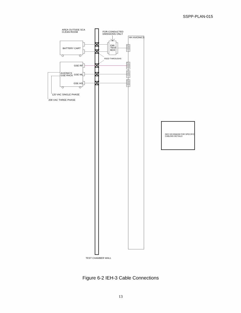
The IEH-3 payload test configuration is shown in Figure 6-1. Figure 6-2
illustrates the cable connections of the test configuration. Additional cabling
between the experiment electronics is not shown. Only those harnesses
required for this EMI test are shown. The flight harness shall be installed
in a flight configuration. The payload structure shall be grounded to the
facility. Figure 6-3 shows the GSE layout outside the SCA room. During all
conducted tests, the payload shall be battery powered via a code 754
supplied +28 +/ - 4 VDC battery cart. For radiated tests, a lab power supply
may be used. 0 AWG power lines will be required to simulate actual flight
interfaces.
During the susceptibility tests, Ground Support Equipment (GSE) will be
connected to the payload and operating. A unique power harness must be
installed between the HH avionics and the battery in order to perform the
conducted emissions and susceptibility tests.
6.2 Payload Special Requirements
The PANSAT ejectable is mounted to a Hitchhiker provided ejection system
which contains pyrotechnic devices. In order to test these systems in the
most efficient manner, special configurations will be used during EMC testing.
The flight pyrotechnic devices will be part of the integrated system and
armed throughout the test. However, since these will be considered category
B explosives, no potential harm to personnel will exist.
6.3 Hitchhiker Ground Support Equipment Configuration
The Hitchhiker Avionics Electrical GSE includes an OSR and ACCESS. The
OSR provides the necessary Orbiter electrical interfaces to the HH avionics
and will be located outside the SCA clean room in Bldg. 7, room 010. The
ACCESS will be located next to the OSR rack. All cables entering the Radio
Frequency (RF) shield room will be covered with aluminum foil and

SSPP-PLAN-015
11
grounded. The HH avionics will be mounted to an Experiment Mounting
Plate (EMP) attached to the bridge (upper truss). The upper truss will be
rolled into the RF clean room.
Customer Ground Support Equipment (CGSE) shall also be used to
control / monitor the payload. The CGSE will interface with the ACCESS.

SSPP-PLAN-015
12
Figure 6-1 Payload Test Configuration
SSPP-PLAN-015
13
BATTERY CART
AVIONICSGSE RACK
120 VAC SINGLE PHASE
208 VAC THREE PHASE
AREA OUTSIDE SCACLEAN ROOM
GSE RF
GSE ML
GSE HO
TEST CHAMBER WALL
EMITESTBOX
FOR CONDUCTEDEMISSIONS ONLY
HH AVIONICS
P001
J001
P006
J006
P007
J007
P008
J008
FEED THROUGHS
SEE GE1556028 FOR SPECIFICCABLING DETAILS
Figure 6-2 IEH-3 Cable Connections

SSPP-PLAN-015
14
RFI ROOM
CABLES TOHH AVIONICS
OSRACCESS
3’ x 3’
CONCAPTABLE
SEHTABLE
SOLCONTABLE
STAR-LITETABLE
UVSTARTABLE
PANSATTABLE
4’ x 6’
Figure 6-3 IEH-3 GSE Layout
SSPP-PLAN-015
15
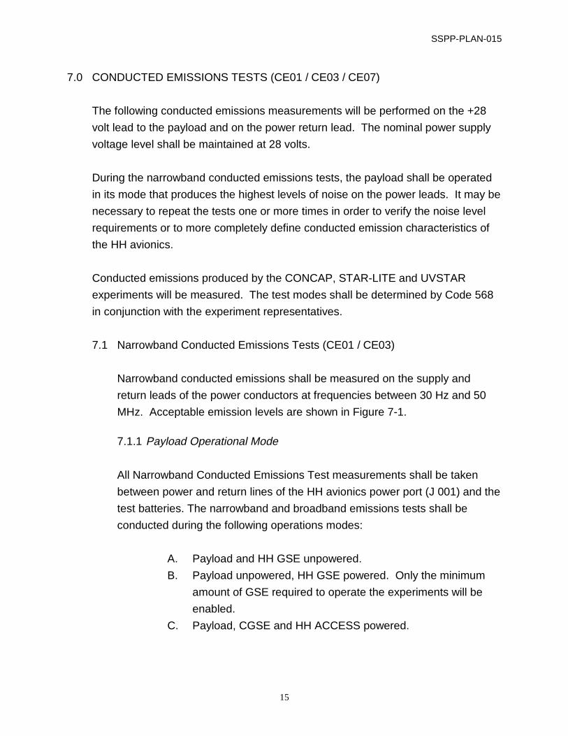
7.0 CONDUCTED EMISSIONS TESTS (CE01 / CE03 / CE07)
The following conducted emissions measurements will be performed on the +28
volt lead to the payload and on the power return lead. The nominal power supply
voltage level shall be maintained at 28 volts.
During the narrowband conducted emissions tests, the payload shall be operated
in its mode that produces the highest levels of noise on the power leads. It may be
necessary to repeat the tests one or more times in order to verify the noise level
requirements or to more completely define conducted emission characteristics of
the HH avionics.
Conducted emissions produced by the CONCAP, STAR-LITE and UVSTAR
experiments will be measured. The test modes shall be determined by Code 568
in conjunction with the experiment representatives.
7.1 Narrowband Conducted Emissions Tests (CE01 / CE03)
Narrowband conducted emissions shall be measured on the supply and
return leads of the power conductors at frequencies between 30 Hz and 50
MHz. Acceptable emission levels are shown in Figure 7-1.
7.1.1 Payload Operational Mode
All Narrowband Conducted Emissions Test measurements shall be taken
between power and return lines of the HH avionics power port (J 001) and the
test batteries. The narrowband and broadband emissions tests shall be
conducted during the following operations modes:
A. Payload and HH GSE unpowered.
B. Payload unpowered, HH GSE powered. Only the minimum
amount of GSE required to operate the experiments will be
enabled.
C. Payload, CGSE and HH ACCESS powered.

SSPP-PLAN-015
16
10 100 1k 10k 100k 1M 100M 100M
FREQUENCY (Hz)
dB µ
A
140
120
100
80
60
40
20
0
Payload Bay
Crew Compartment
Figure 7-1 Narrowband Conducted-Emission on Payload Power Leads
SSPP-PLAN-015
17
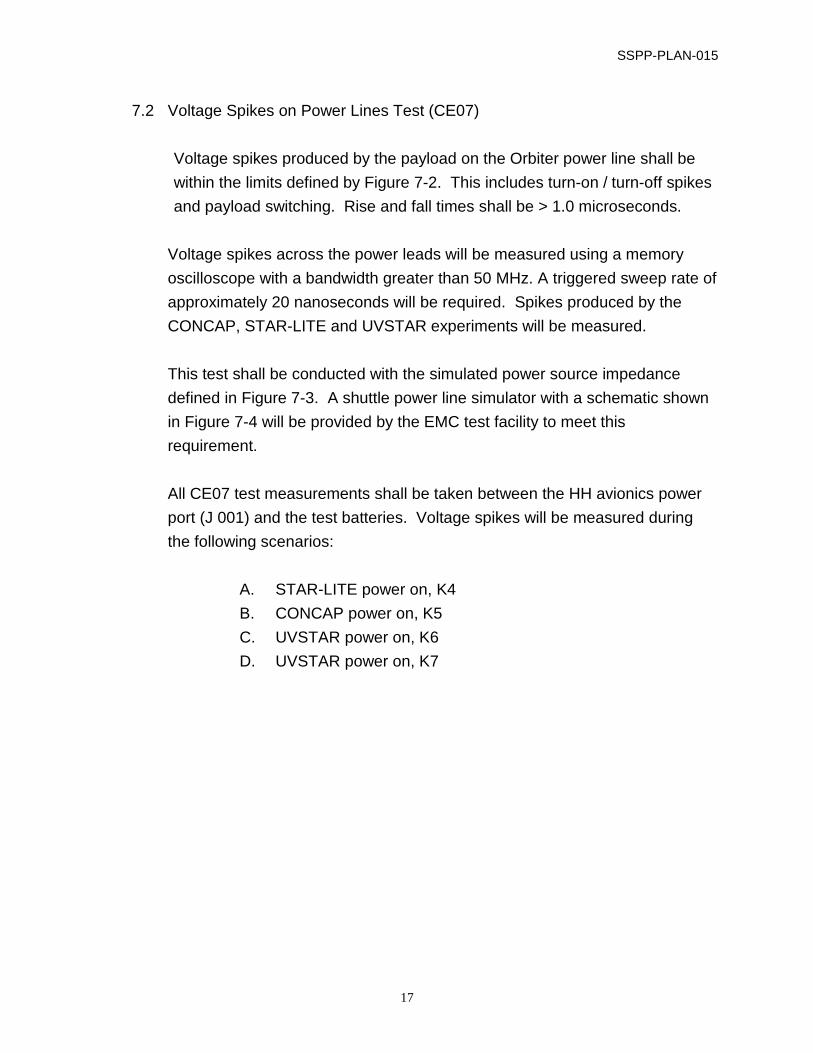
7.2 Voltage Spikes on Power Lines Test (CE07)
Voltage spikes produced by the payload on the Orbiter power line shall be
within the limits defined by Figure 7-2. This includes turn-on / turn-off spikes
and payload switching. Rise and fall times shall be > 1.0 microseconds.
Voltage spikes across the power leads will be measured using a memory
oscilloscope with a bandwidth greater than 50 MHz. A triggered sweep rate of
approximately 20 nanoseconds will be required. Spikes produced by the
CONCAP, STAR-LITE and UVSTAR experiments will be measured.
This test shall be conducted with the simulated power source impedance
defined in Figure 7-3. A shuttle power line simulator with a schematic shown
in Figure 7-4 will be provided by the EMC test facility to meet this
requirement.
All CE07 test measurements shall be taken between the HH avionics power
port (J 001) and the test batteries. Voltage spikes will be measured during
the following scenarios:
A. STAR-LITE power on, K4
B. CONCAP power on, K5
C. UVSTAR power on, K6
D. UVSTAR power on, K7

SSPP-PLAN-015
18
DURATION - SECONDS
DC
VO
LTA
GE
60
50
40
20
0
30
10
-10
1x10⁻⁶
10-5
10-4
10-3
10-2
100
101
10-1
Figure 7-2 Limits on Payload Produced Spikes (Line-to-Line) on DC Power Levels

SSPP-PLAN-015
19
100 1K 10K 100K 1M 10M
FREQUENCY (HZ)
Z (
OH
MS
)
100
10
1.0
0.1
0.01
Figure 7-3 STS DC Power Line Impedance

SSPP-PLAN-015
20
+
-
C1INPUT
POWER
L1 R1
R3
R4
L2 R2
Z TEST SAMPLE
R1, R2 = 0.25 ohm* R3, R4 = 25 ohm C1 L1, L2 = 4 µH
= 19,000 µF (75 V ELECTROLYTIC)
* Value of resistors may be reduced to 0.025 ohms or lower for hardware requiring high levels of power currents
Figure 7-4 Network Schematic for Orbiter Simulation of Impedance
SSPP-PLAN-015
21
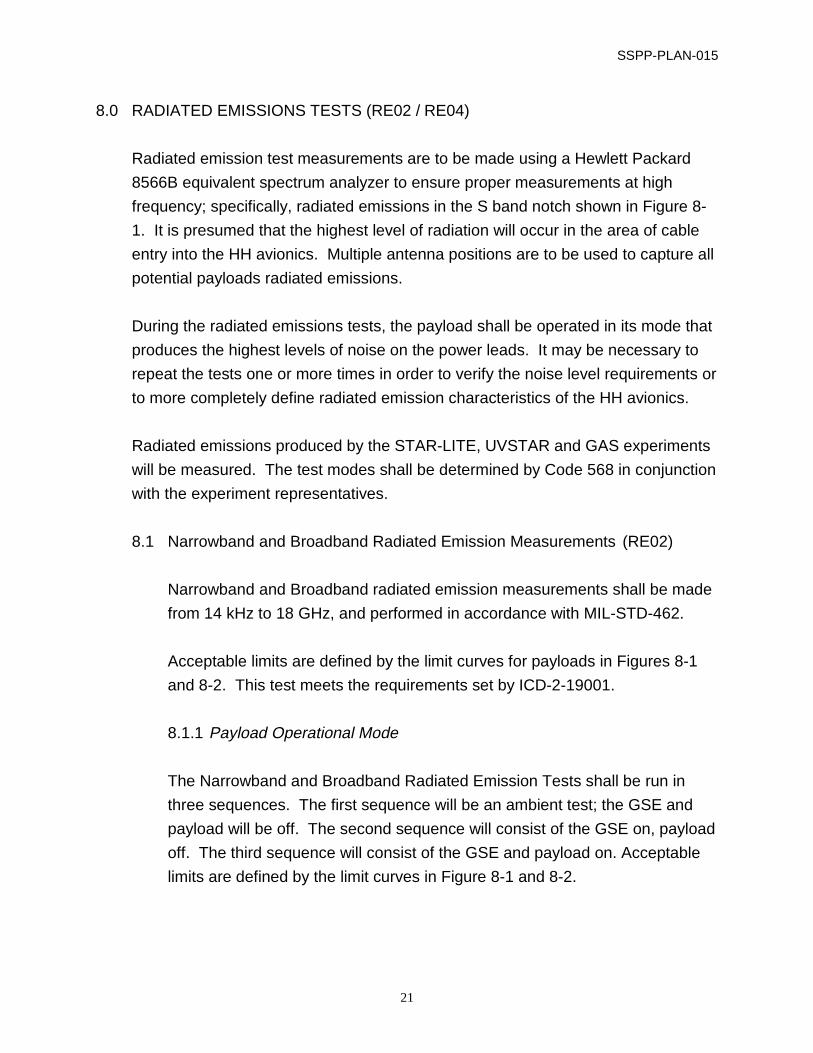
8.0 RADIATED EMISSIONS TESTS (RE02 / RE04)
Radiated emission test measurements are to be made using a Hewlett Packard
8566B equivalent spectrum analyzer to ensure proper measurements at high
frequency; specifically, radiated emissions in the S band notch shown in Figure 8-
1. It is presumed that the highest level of radiation will occur in the area of cable
entry into the HH avionics. Multiple antenna positions are to be used to capture all
potential payloads radiated emissions.
During the radiated emissions tests, the payload shall be operated in its mode that
produces the highest levels of noise on the power leads. It may be necessary to
repeat the tests one or more times in order to verify the noise level requirements or
to more completely define radiated emission characteristics of the HH avionics.
Radiated emissions produced by the STAR-LITE, UVSTAR and GAS experiments
will be measured. The test modes shall be determined by Code 568 in conjunction
with the experiment representatives.
8.1 Narrowband and Broadband Radiated Emission Measurements (RE02)
Narrowband and Broadband radiated emission measurements shall be made
from 14 kHz to 18 GHz, and performed in accordance with MIL-STD-462.
Acceptable limits are defined by the limit curves for payloads in Figures 8-1
and 8-2. This test meets the requirements set by ICD-2-19001.
8.1.1 Payload Operational Mode
The Narrowband and Broadband Radiated Emission Tests shall be run in
three sequences. The first sequence will be an ambient test; the GSE and
payload will be off. The second sequence will consist of the GSE on, payload
off. The third sequence will consist of the GSE and payload on. Acceptable
limits are defined by the limit curves in Figure 8-1 and 8-2.

SSPP-PLAN-015
22
10k 100k 1M 10M 100M 1G 10G 100G
FREQUENCY (Hz)
Ele
ctric
Fie
ld In
tens
ity
(dB
µv/m
)
70
60
50
40
30
90
80
NOTCH FROM 1.77 GHZ TO 2.30 GHZ
NOTCH FROM 259.2 MHz TO 297.3 MHz
COMPOSITE PAYLOAD (PAYLOAD BAY)
INDIVIDUAL EQUIPMENT ITEMS
LOCATED IN CREW COMPARTMENT
14 kHz
18 GHz
14 kHz
18 GHz
Figure 8-1 Unintentional Radiated Narrowband Limits for Electric Field Emission

SSPP-PLAN-015
23
120
110
100
90
80
70
60
dB µ
v/m
/MH
z
FREQUENCY (Hz)
10k 100k 1M 10M 100M 1G 10G 100G
18 GHz
14 kHz
14 kHz
18 GHz
NOTCH FROM 1.77 GHz TO 2.30 GHz
COMPOSITE PAYLOAD IN PAYLOAD BAY
INDIVIDUAL EQUIPMENT ITEM
S LOCATED IN CREW COM
PARTMENT
Figure 8-2 Unintentional Radiated Broadband Limits for Electric Field Emission
SSPP-PLAN-015
24
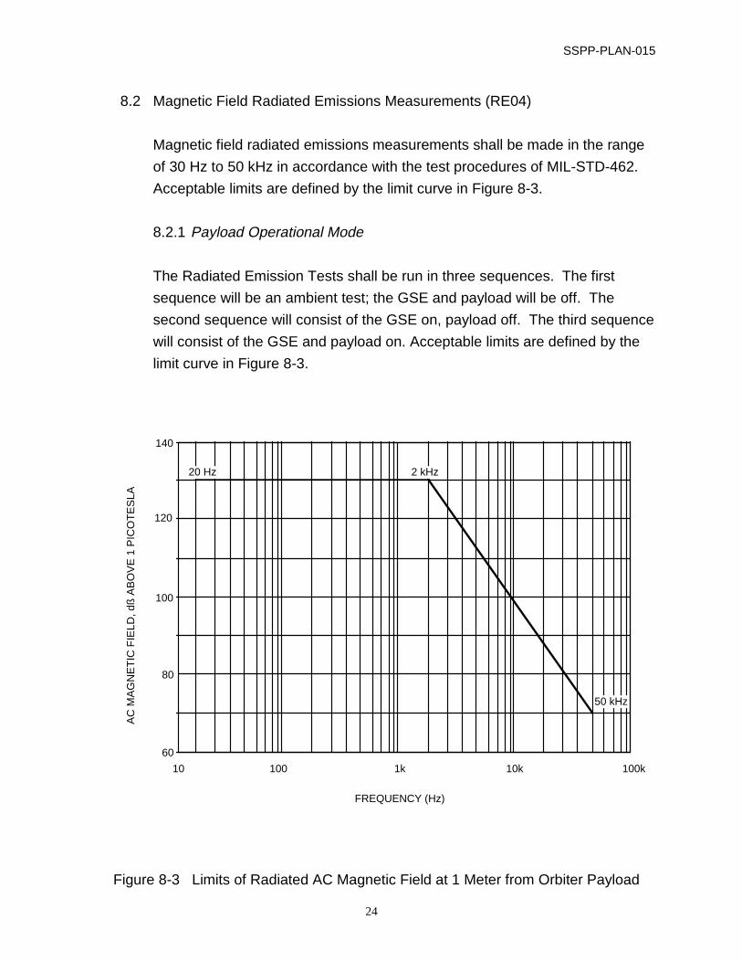
8.2 Magnetic Field Radiated Emissions Measurements (RE04)
Magnetic field radiated emissions measurements shall be made in the range
of 30 Hz to 50 kHz in accordance with the test procedures of MIL-STD-462.
Acceptable limits are defined by the limit curve in Figure 8-3.
8.2.1 Payload Operational Mode
The Radiated Emission Tests shall be run in three sequences. The first
sequence will be an ambient test; the GSE and payload will be off. The
second sequence will consist of the GSE on, payload off. The third sequence
will consist of the GSE and payload on. Acceptable limits are defined by the
limit curve in Figure 8-3.
10 100 1k 10k 100k
FREQUENCY (Hz)
AC
MA
GN
ET
IC F
IELD
, dß
AB
OV
E 1
PIC
OT
ES
LA
140
120
100
80
60
20 Hz 2 kHz
50 kHz
Figure 8-3 Limits of Radiated AC Magnetic Field at 1 Meter from Orbiter Payload
SSPP-PLAN-015
25
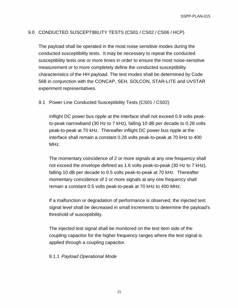
9.0 CONDUCTED SUSCEPTIBILITY TESTS (CS01 / CS02 / CS06 / HCP)
The payload shall be operated in the most noise sensitive modes during the
conducted susceptibility tests. It may be necessary to repeat the conducted
susceptibility tests one or more times in order to ensure the most noise-sensitive
measurement or to more completely define the conducted susceptibility
characteristics of the HH payload. The test modes shall be determined by Code
568 in conjunction with the CONCAP, SEH, SOLCON, STAR-LITE and UVSTAR
experiment representatives.
9.1 Power Line Conducted Susceptibility Tests (CS01 / CS02)
Inflight DC power bus ripple at the interface shall not exceed 0.9 volts peak-
to-peak narrowband (30 Hz to 7 kHz), falling 10 dB per decade to 0.28 volts
peak-to-peak at 70 kHz. Thereafter inflight DC power bus ripple at the
interface shall remain a constant 0.28 volts peak-to-peak at 70 kHz to 400
MHz.
The momentary coincidence of 2 or more signals at any one frequency shall
not exceed the envelope defined as 1.6 volts peak-to-peak (30 Hz to 7 kHz),
falling 10 dB per decade to 0.5 volts peak-to-peak at 70 kHz. Thereafter
momentary coincidence of 2 or more signals at any one frequency shall
remain a constant 0.5 volts peak-to-peak at 70 kHz to 400 MHz.
If a malfunction or degradation of performance is observed, the injected test
signal level shall be decreased in small increments to determine the payload’s
threshold of susceptibility.
The injected test signal shall be monitored on the test item side of the
coupling capacitor for the higher frequency ranges where the test signal is
applied through a coupling capacitor.
9.1.1 Payload Operational Mode

SSPP-PLAN-015
26
During the Power Line Conducted Susceptibility Test, the payload shall be in
a fully operational mode. The GSE shall also be operational during this test.
Acceptable performance is defined as follows:
HH avionics: Avionics telemetry received at
ACCESS within nominal limits.
CONCAP: Telemetry received at CONCAP
CGSE within nominal limits.
Nominal limits shall be defined by
CONCAP Electrical Engineer.
SEH: Telemetry received at SEH CGSE
within nominal limits. Nominal limits
shall be defined by SEH Electrical
Engineer.
SOLCON: Telemetry received at SOLCON
CGSE within nominal limits.
Nominal limits shall be defined by
SOLCON Electrical Engineer.
STAR-LITE: Telemetry received at STAR-LITE
CGSE within nominal limits.
Nominal limits shall be defined by
STAR-LITE Electrical Engineer.
UVSTAR: Telemetry received at UVSTAR
CGSE within nominal limits.
Nominal limits shall be defined by
UVSTAR Electrical Engineer.
PANSAT HESE: Ordnance (NSI’s) remain unfired.
(verified post test)

SSPP-PLAN-015
27
9.2 Power Line Transient Test (CS06)
A transient signal shall be applied across the input power lines in accordance
with the procedures of MIL-STD-461C and 462. According to GEVS, the
applied test transient shall be equal to the power line voltage of 28 volts. The
resulting peak voltage of this transient will be +28 ±28 volts, i.e. +56 volts and
0 volts. However, since the payload (and all other STS payloads sharing the
power bus with IEH-3) can emit turn-on transients of +28 ±30 volts (ICD-2-
19001, 10.7.3.1), the peak voltage of this transient shall be +28 ±30 volts, i.e.
+58 volts and -2 volts. This will provide a 0 dB EMC margin.
The transient shall be applied with a pulse width of 10 micro-seconds at a
variable duty cycle (ICD-2-19001, Figure 7.3.7.2-1).
Due to the sensitive nature of the payload, this transient signal will be applied
in a ramping manner for both peak voltage and repetition rate. When
degraded performance is observed in CONCAP, SEH, SOLCON, STAR-LITE
or UVSTAR that experiment may be turned off while the remaining test
sequence continues. The decision to turn off an experiment or continue with
the test sequence will be made by the IEH-3 test conductor in conjunction
with the EMI Facility operator and the experiments Lead Electrical Engineers.
The test sequence is as follows. Increase the peak voltage offset from +28
volts in 6 increments of 5 volts i.e. ± 5, 10, 15, 20, 25 and 30. At each voltage
level, increase the pulse repetition rate in 6 steps of 10 pulses i.e. 10, 20, 30,
40, 50, and 60. Each pulse rate shall last one minute for a total of six minutes
per each voltage level polarity. Total test duration, excluding equipment or
test set-up and problem resolution, shall be 72 minutes.
9.2.1 Payload Operational Mode
During the Power Line Transient Test, the payload shall be in a fully
operational mode. The GSE shall also be operational during this test.
Acceptable performance is defined as follows:

SSPP-PLAN-015
28
HH avionics: Avionics telemetry received at
ACCESS within nominal limits.
CONCAP: Telemetry received at CONCAP
CGSE within nominal limits.
Nominal limits shall be defined by
CONCAP Electrical Engineer.
SEH: Telemetry received at SEH CGSE
within nominal limits. Nominal limits
shall be defined by SEH Electrical
Engineer.
SOLCON: Telemetry received at SOLCON
CGSE within nominal limits.
Nominal limits shall be defined by
SOLCON Electrical Engineer.
STAR-LITE: Telemetry received at STAR-LITE
CGSE within nominal limits.
Nominal limits shall be defined by
STAR-LITE Electrical Engineer.
UVSTAR: Telemetry received at UVSTAR
CGSE within nominal limits.
Nominal limits shall be defined by
UVSTAR Electrical Engineer.
PANSAT HESE: Ordnance (NSI’s) remain unfired.
(verified post test)
9.3 Power line Transients Caused by STS Hydraulic Circulation Pump (HCP)
There is a special test requirement to perform a conducted susceptibility
test to determine the payloads vulnerability to transients generated by

SSPP-PLAN-015
29
the Orbiter HCP. The test signal to be applied across the power leads is
called out in GEVS 2.5.3.1a (see Figure 9-1), and is as follows:
Saw-toothed transient oscillation
4 volts peak-to-peak
Base frequency 500-700 Hz
Offset from +28 volts to produce +1.5 and -2.5 volt excursions
If a suitable offset cannot be achieved, a signal centered around 2volts
with a peak-to-peak value of 5 volts producing offsets of +/ - 2.5 volts may be
used.
-100 0 100 200 300
TR
AN
SIE
NT
VO
LTA
GE
LIM
ITS
(D
C V
OLT
S)
2.0
1.5
1.0
0.5
0
-0.5
-1.0
-1.5
-2.0
-2.5
-3.0
400 500
0.4v Composite Ripple
Interface Nominal Voltage
Spike Width 1 Millisecond
Figure 9-1 Transient Voltage on the Primary PL Bus Produced by Operation of the
Hydraulic Circulation Pump

SSPP-PLAN-015
30
10.0 RADIATED SUSCEPTIBILITY TEST (RS03)
Radiated susceptibility tests shall be performed at each of the two antenna test
positions used for the radiated emission measurements. The power voltage shall
be maintained at 28 Volts.
During the radiated susceptibility tests, the payload shall be operated in its most
noise sensitive modes. It may be necessary to repeat the tests one or more times
in order to ensure the most noise sensitive measurement or to more completely
define radiated susceptibility characteristics of the HH payload. The test modes
shall be determined by Code 568 in conjunction with the CONCAP, SEH,
SOLCON, STAR-LITE and UVSTAR experiment representatives.
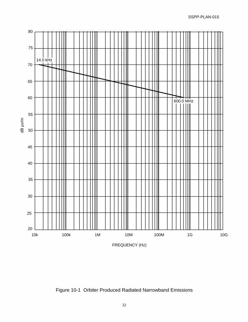
10.1 Susceptibility from Unintentional Orbiter Produced Emissions
The payload shall be tested to determine susceptibility to unintentional
Orbiter emissions. The test shall be performed in accordance with RS03.
The test signal antenna shall be located to simulate the configuration of the
Orbiter’s antenna with respect to the payload. The payload shall be tested to
the E-field specified in Figures 10-1 and 10-2 for narrowband and broadband
Orbiter emissions.
10.1.1 Payload Operational Mode
During the Susceptibility from Unintentional Orbiter Produced Emissions
Test, the payload shall be in a fully operational mode. The GSE shall also be
operational during this test. Acceptable performance is defined as follows:
HH avionics: Avionics telemetry received at
ACCESS within nominal limits.
CONCAP: Telemetry received at CONCAP
CGSE within nominal limits.
Nominal limits shall be defined by
CONCAP Electrical Engineer.

SSPP-PLAN-015
31
SEH: Telemetry received at SEH CGSE
within nominal limits. Nominal limits
shall be defined by SEH Electrical
Engineer.
SOLCON: Telemetry received at SOLCON
CGSE within nominal limits.
Nominal limits shall be defined by
SOLCON Electrical Engineer.
STAR-LITE: Telemetry received at STAR-LITE
CGSE within nominal limits.
Nominal limits shall be defined by
STAR-LITE Electrical Engineer.
UVSTAR: Telemetry received at UVSTAR
CGSE within nominal limits.
Nominal limits shall be defined by
UVSTAR Electrical Engineer.
PANSAT HESE: Ordnance (NSI’s) remain unfired.
(verified post test)
SSPP-PLAN-015
32
dB µ
v/m
FREQUENCY (Hz)
10k 100k 1M 10M 100M 1G 10G
14.0 kHz
600.0 MHz
80
75
70
65
60
55
50
45
40
35
30
25
20
Figure 10-1 Orbiter Produced Radiated Narrowband Emissions

SSPP-PLAN-015
33
FREQUENCY (Hz)
10k 100k 1M 10M 100M 1G 10G
14.0 kHz
300.0 MHz
dB µ
v/m
/MH
z
130
125
120
115
110
105
100
95
90
85
80
75
70
Figure 10-2 Orbiter Produced Radiated Broadband Emissions

SSPP-PLAN-015
34
11.0 PRELIMINARY TEST RESULTS
During the EMI testing, Code 754 shall provide preliminary test data to the test
conductor. If during emissions testing, an exceedance occurs, additional testing
may be performed to isolate the cause of the exceedance. If during the
susceptibility testing, the avionics or the experiments do not perform within
nominal limits, additional testing may be performed to isolate the cause of the
anomaly.
12.0 RESPONSIBILITY ASSIGNMENTS
12.1 Responsibilities of Code 568
A. Preparation and setup of the test item.
B. Transportation and handling of the test items.
C. Provide cabling from the ground support equipment needed to
operate and monitor the test item during the test program.
D. Provide cabling from the ground support equipment to the test items.
1. One set of cables are needed with breakout box power leads in
order to apply current probes for conducted emission testing and to
insert a secondary transformer for conducted susceptibility testing.
2. One set of flight cabling is needed for radiated emission and
susceptibility testing.
E. Provide ground support equipment for control monitoring of test items.
F. Operation of instrument during testing.
G. Participation in Data Analysis.
H. Documentation of all malfunctions using GSFC malfunction report
system as defined in GMI-5310.1 All procedures and problems shall be
maintained in certification logs per GSFC-303-PROC-001.
12.2 Responsibility of EMC Test Group Code 754.2
A. Operation of EMC Test Equipment.
B. Conduct tests in accordance with test procedures and good MIL-STD-
461 / 462 test practices.

SSPP-PLAN-015
35
C. Calibration of EMC Test Equipment.
D. Documentation of tests including Polaroid pictures (black & white) of the
test setups.
E. Generation of formal EMI test report; 2 duplexed copies to M. Wright
/568, within one month of test completion.
F. Provide Fairchild battery cart to power test items. Battery cart recharging
is required every evening throughout EMC testing.
12.3 Responsibility of Code 300 Flight Assurance Office
A. Verify EMI test equipment is in calibration.
B. Verify item under test configuration.
C. Witness test as required.