electrolytes and separators for high voltage li ion cells · ... energy density and power output of...
TRANSCRIPT

Electrolytes and separatorsfor high voltage Li ion cells
(an investigation of sulfone-basedelectrolyte solvents)
C. Austen Angell
Department of Chemistry and Biochemistry,Arizona State University
This presentation does not contain any proprietary,confidential, or otherwise restricted information
March 11, 2011 Project ID: ES100

Overview
Timeline:Start: May 2010Finish: Dec./2013
Budget:$709,977
Funding received in FY 2010for 2010 and 2011
$249,977Funding for FY 2012
$230,000
Barriers:•High viscosities, and melting points, of existing examples.
•Lack of information on additives and mixtures
•Safety issues: flammability
•Sepataor issures: containment impedance and toughness
Partners:•Oleg Borodin, U. Utah•Goying Chen, LBL•Brett Lucht, U. Rhode IslandJason Zhang, PNNL

Relevance: Once conductivity has been maximized, energy
density and power output of VT power train can only be increased by increase of cell voltage. REQUIREMENT: high voltage stable electrolyte and solvent
Background needed
· Aliphatic suifones, especially those with open-chain alkyls,'" are recognized by organic chemists as unusual lor their combination ol polarity with resistance to both oxidation and reduction .1'
[Chemically. aliphatic cyclic sulfones are more easily reduced (ca. 100 times as last) than open-cham sullones.) The simples! mem-
but Dimethyl sulfone Diethyl sulfone Dipropyl sulfone
(CH3hS02
(EthS02 etc
OMS
Try destabilization of crystal lattice by making the molecule asymmetrical. ~
--~~--------------------------------------.
T m = 35°C: eutectic with OMS ·- 25°C
High Anodic Stability of a New Electrolyte Solvent: Unsymmetric Noncyclic Aliphatic Sulfo, n_e __ -,
K. Xu .. and c. A. Angell~ Is 0 9 v !! I J Electrochem Soc., Vol 145, No. 4, A ril1998

Background: A 5.9 volt window ! Kang Xu and CAA., 2.5 J. Electrochem. Soc . 145, L70 998 . 2.0
LS
1.0 411( E
:::::. 0.50
0.0
For capacitative -0.50
storage. note that the -1.0
energy of a capacitor is given by: ·1 .5
E =-§- cpV2
I
8.0
Q
.. b
~ I
LI,.,Mn,o • o c .. thode
• lll.hlum anode
~ I -. ----------------~ ~ .' o~wct.•rg« celt vo41-..
pr:otecll on ·
6.0 4.0 ~.0 0.0
ElY vs. ll
·2.0

Background:The promise of SUifones: conductivity of FEMS vs EC:DMC
US Patent No. 6,245,465 Angell et al., 2001
Visit by Toyota Delegation 2005
--. : _. : "'V.l'K . • . •• ~ ft:,..'f?C<oct:f',, .~
-2 1- • •• • •• • . U[~· : ~·- ·• -oo : : -•· . no • : .. 00
~ ~ ··· : o • ~ . 0 0 . ... . 0 "7 : ~# : : 00
5 -3 - ~ "s~ ! ~ o ~ F el-l c.,.......... ""cH: : ... 3 . 2 3 ' l:l
Methylethoxymethylsulfone g> (MEMS)
• 0 . 0
...
Melting point 7°C ckura:h,emu~ty \ClmiiiUIIIOilllltlt
.. , ........ .-~-US Patent No. 6,245,465 Angell & Sun., 2010 (DOW inc option)
- 4 .
• 1M LIPF6-ECIDMC (1 :1 ) 0 1M LiCI04-FEMS
.A 1M LiTFSI-EMS
... ...
-5~~,~~~·-~·~:·~~·~: ~~· -~· ~ 2.4 2.6 2.8 3.0 3.2 3.4 3.6 3.8 4.0 4.2
1 000/T (1/K )

Background: And sulfones seem to protect lower EC "window"(but higher fluidity) co-solvents
Work of Kang Xu (JECS,2002) FPMS is CF3CH2CH2[S02]CH3
. I 0.1 mAcrri, i DMC :.
)
) EMC :
j:l-------.. I FPMS/EMC
__ ;~\ :PMS/DMC)
3 3 .5 4 4 .5 5 5.5 6 6.5
~ cP 0') ~ ...
Forms good SEI
5 ' ' o o I I
...--~~ ~ -4 1-!P ti{• ; \\ - 1:2 (0.87)
~ 0 • 0 0
3 1-
t -
- 2 -Q
1:1 (0.76) 1:2(Qr)
> 1 - 1 :1 (0.82}-
EN vs. Li
0 0.5 1 1.5 2 2.5 3 3.5 ·2
Capacity/mAhcm
But T m of FPMS is 56°C Q

I OBJECTIVES and milestones I 1. Identify unstudied sulfones for evaluation 2. Determine key properties, conductivity and "windows",
taking any commercially avai lable cases first. (a) pure sulfones (Dec. 10, 201 0) (b) mixed sulfones (c) mixed sulfones and carbonates( Dec. 10, 201 0)
3. Synthesize new sulfones (a) fluorinated (March 11 , 2011 ) (b) fluorinated oxygenated (March 11, 2011 )
4. Test sulfolane-based cases by synthesis, following predictions of collaborator (Oieg Borodin) (March 11, 2011 )
5. Conceive new strategies (second year. . . achieved already)
6. Commence investigation of novel separator concept (March 2011 )

Name Tm(oC)
Tb(oC)
η(cP)
ε σ25(mS/cm)
Window(V vs Li/Li+)
Dimethylsulfone (DMS)
110 (238) - - - -
Methanesulfoneyl fluoride (MSF)
- 123 - - 3.0 (1M LiTFSI) 5.3/LiTFSI
Methanesulfoneyl chloride (MSCl)
-33 160 1.97@25 - - 3.7/LiPF6
Ethylmethylsulfone (EMS)
36.5 (240) - 95 6.3 (1M LiTFSI)3.2 (1M LiPF6)
5.9/LiTFSI
EMS-DMS eutectic(85:15 mol/mol)
25(Te)
- - - 2.2 (0.5 M LiTFSI)
-
Methylpropylsulfone (PMS)
28 (245) - - - -
Trifluoromethylmethylsulfone (FMMS)
- 130 - - - -
Trifluoroethylmethylsulfone (FEMS)
- - - - 8.9 (1M LiClO4) -
Trifluoropropylmethylsulfone (FPMS)
56 180 - - 0.035 (1M LiTFSI)
5.8/LiPF6+DMC
Sulfolane 27 285 [email protected]@30
(1M LiPF6)
60 3.1(1M LiTFSI)2.5 (1M LiPF6)
5.8/LiPF6
3-fluorosulfolane 0.7 (303) 29.1@30(1M LiPF6)
- 0.74 (1M LiPF6) 5.6/LiPF6
SOO
H3C CH3
SOO
F CH3
SOO
Cl CH3
SOO
H3CH2C CH3
SOO
H3CH2CH2C CH3
SOO
F3CH2CH2C CH3
SO
OF
SO
O
SOO
F3CH2C CH3
SOO
F3C CH3

Sulfones
MSF
FPMS
MSCl
Viscosity-conductivity correlation (Walden rule)

2.4 2.6 2.8 3.0 3.2 3.4 3.6 3.8 4.0 4.2- 7
- 6
- 5
- 4
- 3
- 2
- 10oC25oC100oC
log σ
(Scm
-1)
1000/T ( 1/K)
1M LiTFSI-EMS 1M LiClO4-FEMS 1M LiTFSI-FPMS 1M LiTFSI-MSF
NEW DATA:Specific
conductivitiesof various Li
salts in sulfonesolvents.
The puzzle oflow-boiling
FPMScf. MSF
ACCOMPLISHMENTS

The need for mixtures (see Xu review)
No single solvent can satisfy simultaneously all solvent needs
e.g Large dipole moment needed for overcoming crystal lattice energy (dissolving) causes high melting point and high viscosity, so low conductivity.
Resolution: mix with co-solvent of low dielectric constant and low boil ing point. Thus EC-DMC 2 ,----,.-----,~----r~----.-~~
Mixing also reduces freezing point • 1M U~F6 in St.lfolane 31t'C • IM LIBF4 in Sulfolano 30'C // a IM LITfO In Slifolane 3a'C [2]
lonicity. How free are the ions from one another? Are we optimizing the decrease of viscosity, or losing some of the ions to associated pairs?
The fi rst Walden plot for Li battery electrolytes
< "'
1 Y IM LIPFS in EC/OMC 1:1 25' C / T . (' /
;;;.~Jo
~:~ : 0f(j
,?::> J:) _ ,
Increasing fluidity - 2 ~-.._.._..__.._..___,J
-2 - 1 0 2
log ~ ' (Poise ' )

The mixture strategy: EMS vs ' ,.
IOlmA<mi OMC i new mixtures. -})··· / Earlier work from Kang Xu & CM ~ (JECS 2002) suggested mixture
_ji\ FP MS IOMCJ synergism 10
_1
ACCOMPLISHMENT
~-~ •••• ' L ~ •• . ~[:;,·~
•• • • • • 1.0M liPF6 in EMS-DMC 1: by wt
1:::, 1.0M LJPF6 1n EMS-MSF 1: bywt
• 1.0M LIPF6 in EMS
2.S 3 .0 3.2 3.4 3.6
1 000/T (1/K )

~
~
• E u
(J) ~
>--·s: ·.;::: u :::1 -o c 0 u u c 0
Other interesting mixtures (with high fluidity MSF)
Accomplishment slide EMS-MSF not only has good conductivity and window, but also good Li deposition and striooino. i.e. oood SEI (next)
10-~
10·3
10"'
Temperature (0 C)
80 50 25
lOr--------------------.------, I I . ' ~
~~. e ••E 0.8
. ~~~··. ~ io:>D Ooo:a·.· u"~ ~6 c ~ . 0 0 0 ............... c, 0.6
: 0 ¢ 0 ci"' T, -~ 0 0 ~
0 ., 04
Wi================~~o ~ p I,OM UPF6 in EMS-DMC 1.1 by wl} I u 02 A 1.0M LIPF61n EMS-MSF I :1 by WI}
o 1.0M UPF6 in EMS} T 1.0M LiPF6 in EMS-MSCI 1:1 by wt} o 1.0M UPF61n EMS-CF3S02CH3) (FMMS)
2.8 3.0 3.2 3.4 3.6
1 OOOfT ( 1/K)
3
- 1M UTFSI-EM S - 11A UTFSI-MSF
Working elaetrode: PI Reference, counter ela<:trocle. Ll Scan rate: 1 mV/~
4 5
E (1/ ) vs. Li
6 7
ACCOMPLISHMENT SLIDE
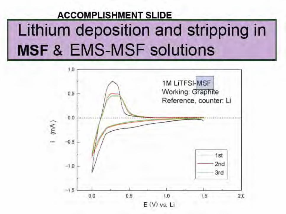
Lithium deposition and stripping in MSF & EMS-MSF solutions
~
1
1.0.------------,
0.5
1M LiTFS~MS~ l Working: rap 1 e Reference, counter: Li
00 .............. ~ ........... ~ ........ ~~···· · ...... ....... .
·- -o.5
- 1st
- 1.0 - 2nd - 3rd
0.0 0 .5 1.0 1.5 2 .(
E (V) vs. Li

Lithium deposition and stripping in MSF & EMS-MSF solutions From Xu and Angell JECS (2001)
I - I/\ I I f .......... -,..._ .. _ __ ~
- j r- FPMSIEMC r{
- /1 _:::::::=~-~ _,.. EiBS/EM C
-
EiPSIEMC
f- ~- -7 -r::c. -\ ! .. EMSIDMC
~ \ J I -
1
v· 0 .1 mAle~
0 0.5 1 1 .5 2
E/V vs. Li
I . '
•
Accomplishment slide: formation of effective SEI in EMS-MSF solution
E ( V) vs. Li
1M LiPF6 EMS-MSF (1:1) Working: Graphite Ref, Counter: Li
1st

ACCOMPLISHMENT SLIDE
Fluorination can improve fire resistance

SL
SL(Fs)
Contribution from Collaborating laboratory- Oleg Borodin
Fluorinated Solvents * Influence of sulfolaue fluorination on the solvent oxidative stability, transport properties and its ability to coordinate Li+ has been investigated complementing e:q>erimentaJ studies that are currently performed by Austen Angell group (ASU)
The Li+fsolvent binding energy (in kc.allmol) from QC
Li+/SL Li+/SL(FJ Lt/SL(Fg) Li+!Ec Li+/DMC
MP2/cc-pvTz -52.7 -40.8 -29.5 -47.5 -40.9
orMP2/aug-
cc-pvTz
Solvent self-diffi1sion coefficient
T(K) 303 303 303 313 298 D (10·10 m2/s) 1.1 2.5 4.7 8 25.4 * Completely fluorinated SL(F s) is not expected to be good solvent
for typical Li salts sue h as LiPF 6
or LiTFSI.
* Semifluorinated sulfolaue SL(F 4) is expected to have lit Wum salt dissociation similar to DMC, while SL(F4) dynamics is predicted to be a factor of 2.5 faster than SL but a factor of five slower than DMC.
OTHER COLLABORATIONS: The order-disorder transition in LiNixMn2_x0 4 (with Guoying Chen, LBL)

ACCOMPLISHMENT/COLLABORATION SLIDE
I Sulfolane-based systems I With collaboration of Oleg Borodin (U. Utah)
75 50 25 Temperature (oC)
• • 10_, • • • ,...... <:! <J • • • - <l I .. () · ~ • • E . ..... . ~ ..
0 ~ ~ i (/) • ,. ";', 1 a~ • ., ., • • .. "' " ., . ' -~ • 2: ..
" • ..... 0 • EC:DMC= 'I :·1 • :I • S ulfolene -o .. c 8 10 .... .. • 3F sul1olane .&
And a ... FEOMMS
• 3F sulfolane :DMC=·J: 1
fluorinated <I FEOMMS:DMC=1 :·1
ethersulfone 10-0 ' ' ' ' ' 28 30 32 34 36 38 4.0
Follow-up of US patent 6,245,465 I 000/ K (1 / K)

ACCOMPLISHMENT SLIDE
Good electrochemical aspects of fluorinated sulfolane • Complete deposition and subsequent stripping of Li m
fluorinated sulfone. No extraneous processes. • Excellent wide electrochemical w indow
2.0
1.5 - ·- 1M LiPFG m Sulfolane
~
N 1.0 -
E 0 0.5 -...,
<{ E 0.0 ~
>-..... -0.5 '0
;~~----~·~?~--------/ c .,
-o i 2 ..... c C]) ... 8 ~
- 1M LiPF6 in 3F-Sulfolane
J <.>
4
0
0 2 3 4 5 0
v (Lilli+)

I NEXT: Keeping the electrolyte in place I The separator problem Electrolyte is mobile liquid: It can be kept
Bottled electrons at high pressure
e.g., Li metal
Lc
electrolyte <~
,e.~~u~niC
insulator, ionic short) mobile Li• I
Empty bottle
I Cu+ or Ni2+ (Zebra) or LiNiMn0 4
ad prk)
•
t
in the right place by 1. soaking it up in some sort of sponge: porous
medium with wettable surfaces, 2. or creating a solid around it by using a -
polymerizing component which is then reacted.
EXAMPLES 1 . Celgard is a microporous polypropylene
membrane surface-derivatized to soak up carbonate solvents.
2. methacrylate can be added to the electrolyte and then thermally, or by light, polymerized to create a gel (costs conductivity)
NOW: a novel solution - nanoporous membrane strategy: the Maxwell slat net by rigidity percolation.

TECHNICALBACKUP SLIDES

Solvenl
PC
llC yBL
'(VL
Nl\10
-1 DMC I
DEC
EMC
EA
Mil
ED
From K. Xu, Chern. Reviews Chem_ Rev. 20 04, 1 04~ 4303r- 4417
and Esters as Electrolyte Solvents Structure 1\f. W I 1'n/'C r,;•c TlfcP € Dipole Tr "C dtgcmJ, 25 (IC
zs•c 25 'C Moment/deb • cr 88 36.4 248 1.90, 89.78 4.61 160 1.321 (40 •q
l)-o 102 -48.8 242 2.53 64.92 4.81 132 1.200
116 -53 240 3.2 53
C)= 86 ·43.5 204 1.73 39 4.23 97 1.199
0· 100 -31 208 2.0 34 4.29 81 1.057
! JO L 15 270 2.5 78 4.52 110 1.17
(;:-o
yt~ 90 4.6 9 1 0.59 3.107 0.76 18 1.063 (20 •q
0 118 -74.3. 126 0.75 2.805 0.96 31 0.969 .....-..~
............... ~0 ...... 104 -53 L 10 0.65 2 958 0.&9 1.006
~~ 88 -84 77 OAS 6.02 • _, 0.902
0
~ ...... 102 -84 102 0.6 II 0.898
~ 116 -93 120 0.71 19 0.878

Issues with liquid electrolytes
1. Ionic shorts…. Wot to do?
2. With in situ polymerization to yield gel, the conductivity decrease always seems to be larger than tortuosity constants would e expected to account for.
3. Conductivity reduction: with celgard the reduction in conductivity should just decrease by a tortuosity factor
4. A new idea, the variable nanoporous net the Maxwell rigidity, and the Phillips-Thorpe rigidity percolation model