electrochemistry doi: 10.1002/anie.201300947 bipolar...
TRANSCRIPT

ElectrochemistryDOI: 10.1002/anie.201300947
Bipolar ElectrochemistryStephen E. Fosdick, Kyle N. Knust, Karen Scida, and Richard M. Crooks*
AngewandteChemie
Keywords:electrochemistry · materials science ·sensors
In memory of Su-Moon Park
.AngewandteReviews R. M. Crooks et al.
10438 www.angewandte.org � 2013 Wiley-VCH Verlag GmbH & Co. KGaA, Weinheim Angew. Chem. Int. Ed. 2013, 52, 10438 – 10456

1. Introduction
The objective of this Review is to introduce biological andphysical scientists to the concept of bipolar electrochemistrywith a view toward expanding its scope in new and interestingdirections. This is a worthwhile goal, because the broadadoption of electrochemical methods by those working inother subdisciplines of science in recent years has under-scored some shortcomings of existing techniques, apparatuses,and theory. These include the difficulty of making directelectrical contact to nanoscale electrodes, maintaining controlover and reading out very large arrays of electrodes simulta-neously, controlling electrodes that are mobile in solution,maintaining a non-uniform potential difference over thesurface of an electrode, and using electrodes to control localsolution potentials. In this Review, we will show that all ofthese aspects of electrochemistry can be addressed, at leastpartially, using bipolar electrodes (BPEs).
A more detailed summary of the principles underpinningbipolar electrochemistry will be presented in Section 2, but itis instructive to provide a very brief overview now. Scheme 1
shows a typical experimental configuration used for carryingout bipolar electrochemistry. Here, the driving electrodesapply a uniform electric field across the electrolyte solution,and the resulting faradaic electrochemical reactions at theBPE are shown occurring at the anodic (blue arrow) andcathodic (red arrow) poles of the BPE. As discussed later, theinterfacial potential difference between the solution and BPEis highest at the ends of the electrode, so faradaic processesare always observed there first.
Consider the following simple thought experiment basedon the electrochemical cell shown in Scheme 1, a platinumBPE, and an aqueous solution containing a dilute, inertelectrolyte. When the power supply is turned on to, forexample, 1 V, no faradaic reactions are observed at either thedriving electrodes or the BPE. However, at a critical voltagethat depends on a number of experimental factors, bubblesare observed at the poles of the BPE. Analysis would showthat those at the cathodic pole are hydrogen and those at theanodic pole are oxygen. In other words, even though the BPEis an equipotential surface (or nearly so), the electrolysis ofwater is occurring at its two poles. Importantly, charge mustbe conserved at the BPE, and therefore the rates of formationof 1=2 O2 and H2 are the same. Faradaic reactions might alsooccur at the driving electrodes, but although this is usuallya nuisance it does not directly affect the BPE. We wish toemphasize that this is an oversimplified version of bipolarelectrochemistry, but more details and experimental nuanceswill be discussed later.
The main focus of the present article is on interestingfundamentals and applications of bipolar electrochemistry
A bipolar electrode (BPE) is an electrically conductive material thatpromotes electrochemical reactions at its extremities (poles) even in theabsence of a direct ohmic contact. More specifically, when sufficientvoltage is applied to an electrolyte solution in which a BPE isimmersed, the potential difference between the BPE and the solutiondrives oxidation and reduction reactions. Because no direct electricalconnection is required to activate redox reactions, large arrays ofelectrodes can be controlled with just a single DC power supply oreven a battery. The wireless aspect of BPEs also makes it possible toelectrosynthesize and screen novel materials for a wide variety of ap-plications. Finally, bipolar electrochemistry enables mobile electrodes,dubbed microswimmers, that are able to move freely in solution.
From the Contents
1. Introduction 10439
2. Fundamentals of BipolarElectrochemistry 10440
3. Materials Preparation andFabrication 10444
4. Sensing and ScreeningApplications 10446
5. Bipolar Electrode Focusing 10449
6. Microswimmers 10452
7. Summary and Outlook 10454
Scheme 1.
[*] S. E. Fosdick, K. N. Knust, K. Scida, Prof. R. M. CrooksDepartment of Chemistry and Biochemistry and the Center for Nano-and Molecular Science and TechnologyThe University of Texas at Austin105 E. 24th St., Stop A5300, Austin, TX 78712-1224 (USA)E-mail: [email protected]: http://rcrooks.cm.utexas.edu/research/index.html
Bipolar ElectrochemistryAngewandte
Chemie
10439Angew. Chem. Int. Ed. 2013, 52, 10438 – 10456 � 2013 Wiley-VCH Verlag GmbH & Co. KGaA, Weinheim
that have emerged since about the year 2000, but it isimportant to note that bipolar electrochemistry has beenaround for many years. Beginning in the 1960s, Fleischmann,Goodridge, Wright, and co-workers described fluidized bedelectrodes, where a voltage applied between two drivingelectrodes enables electrochemical reactions at discreteconductive particles.[1–6] Since these early studies, bipolarfluidized bed electrodes have been used in applicationsranging from improving the efficiency of electrosyntheses,[7–9]
photoelectrochemical cells,[10, 11] and even batteries.[12] Bipolarplate technology is critical for polymeric electrolyte mem-brane (PEM) fuel cells where the plates form a series ofBPEs.[13,14] Additionally, neuronal behavior can also bemimicked using short-circuited microbands which act asa BPE, forming logic gates.[15]
During the past 15 years or so, many interesting bipolarelectrochemical experiments have been presented in theliterature, and some of these are discussed in a recentlypublished review article.[124] Our own group has exploreda number of fundamental aspects and applications of bipolarelectrochemistry. For example, Figure 1a is an optical micro-graph of a microfabricated BPE array consisting of 1000electrodes.[16] When a sufficiently large driving voltage isapplied to the array, electrogenerated chemiluminescence(ECL) is produced at the anodic pole of each BPE (Fig-ure 1b). The important result of this experiment is that thewireless capabilities of BPEs allow arbitrarily large arrays ofelectrodes to be powered in a very simple setup.
A number of groups have shown that bipolar electro-chemical reactions can be used to induce motion inobjects.[17–20] An illustrative example from Kuhn�s group isshown in Figure 2.[21–23] Here, bubbles produced by electro-chemical reactions (i.e., H2 or O2) generate sufficient
propulsion to induce the movement of small BPEs. Composi-tional or chemical gradients can be synthesized on BPEs, ashas been elegantly demonstrated by Inagi, Fuchigami, and co-workers, who carried out position-dependent doping ofelectroactive polymers (Figure 3).[24, 25] Our group has alsoinvestigated BPEs as a means of enriching and separatingcharged species electrokinetically. In Figure 4, a single AuBPE is used to locally enrich several different chargedmarkers in a single microchannel.[26] This approach makes itpossible to concentrate analytes up to 500 000-fold in a highlycontrolled zone.[27–33] Finally, arrays of BPEs can be used fora variety of sensing and screening applications,[16, 34–44] whichwe will discuss in Section 4. Further explanation and dis-cussion of these types of bipolar electrochemical experimentsare included in later sections.
2. Fundamentals of Bipolar Electrochemistry
2.1. Relationship Between Driving Electrodes and a BPE
A key point for understanding wireless bipolar electro-chemistry is that the poles of a BPE are oriented in theopposite polarity of the driving electrodes (Scheme 2a). Thiswas clearly demonstrated by Manz and co-workers whoplaced a Pt wire in a weighing boat filled with a pH indicatorsolution.[45] As shown in Figure 5a, application of 30 Vbetween the red and blue wires (driving electrodes) causesthe pH of the solution at the positive driving electrode(anode, red) to decrease (orange color) due to wateroxidation and concomitant production of H+. Likewise,water reduction at the negative driving electrode (cathode,blue) leads to formation of OH� , an increase in pH, and the
Richard M. Crooks is presently the Robert A.Welch Chair in Materials Chemistry at TheUniversity of Texas at Austin. His scientificinterests include electrochemistry, chemicalsensing, and catalysis. He has publishednearly 250 research papers and is the recip-ient of several awards including the CarlWagner Memorial Award of the Electro-chemical Society and the American Chem-ical Society Electrochemistry Award.
Stephen E. Fosdick received his B.S. inChemistry from Iowa State University in2009, where he worked in the lab of Prof.Emily A. Smith. He is currently a graduatestudent in the group of Prof. Richard M.Crooks, where his current research focuseson the development of electrocatalyst screen-ing platforms using bipolar electrochemistry.
Kyle N. Knust earned his B.S. in chemistryfrom the University of Evansville in 2009.He also performed research in the lab ofProf. Dennis G. Peters at Indiana University.He is currently a graduate student in thegroup of Prof. Richard M. Crooks at TheUniversity of Texas at Austin with researchfocused on bipolar electrochemistry and thedevelopment of lab-on-a-chip technologies.
Karen Scida studied chemistry at the Univer-sity of Texas San Antonio where she workedin the lab of Prof. Carlos Garcia. She iscurrently a graduate student in the group ofProf. Richard M. Crooks at the University ofTexas at Austin. Her scientific interestsinclude developing paper-based sensors aspoint-of-care technology and the design ofbipolar electrodes for their analytical applica-tion in microfluidics.
.AngewandteReviews
R. M. Crooks et al.
10440 www.angewandte.org � 2013 Wiley-VCH Verlag GmbH & Co. KGaA, Weinheim Angew. Chem. Int. Ed. 2013, 52, 10438 – 10456

observed purple color of the indicator. In Figure 5b, a U-shaped Pt wire (BPE) has been inserted between the drivingelectrodes, and the change in color of the indicator demon-strates that water electrolysis occurs at its ends, even though itis not in direct electrical contact with the power supply.Moreover, the relative positions of the colors reveal the polesof the BPE are oriented in the opposite polarity of the drivingelectrodes.
Figure 1. a) Optical micrograph of an array of 1000 Au BPEs. Each BPEis 500 mm long and 50 mm wide, and the electrodes are spaced by50 mm vertically and 200 mm horizontally. b) Luminescence micrographshowing the ECL response of 5 mm [Ru(bpy)3]
2+ and 25 mm tri-n-propylamine (TPrA) in 0.10m phosphate buffer (pH 6.9) whenEtot = 85.0 V. c) Photograph of the bipolar electrochemical cell showingthe BPE array immersed in electrolyte solution contained withina poly(dimethylsiloxane) (PDMS) reservoir. The two alligator clips areattached to stainless steel driving electrodes that span the array.d) Plot of ECL intensity vs. pixel number showing the uniformity of theECL response over the rows of BPEs indicated by the white arrows in(b). The ECL intensity varies by no more than 10 %, indicating thatDEelec is uniform over the entire array. Reprinted (adapted) withpermission from Ref. [16]. Copyright 2008 American Chemical Society.
Scheme 2.
Figure 2. a) Schematic illustration of bipolar electrochemical watersplitting on a conductive microbead. b) Optical micrograph of a 1 mmdiameter stainless steel bead experiencing an electric field of1.6 Vmm�1 in 24 mm H2SO4. The cathodic pole is located on the leftside of the bead and the scale bar indicates 250 mm. c) Motion ofa 285 mm diameter glassy carbon microbead in a microchannelexposed to a 5.3 Vmm�1 electric field in 7 mm H2SO4 (scalebar = 100 mm). d) Scheme showing proton reduction and hydroqui-none oxidation on a BPE sphere. e) Motion of a 1 mm diameterstainless steel bead exposed to a 1.3 Vmm�1 electric field in 24 mm
HCl and 48 mm hydroquinone (scale bar = 1 mm). f) Motion ofa 275 mm diameter glassy carbon microbead in a microchannel witha 4.3 Vmm�1 electric field in 7 mm HCl and 14 mm hydroquinone(scale bar = 100 mm). Reprinted by permission from Macmillan Pub-lishers Ltd, Nature Communications, Ref. [21], copyright 2011.
Bipolar ElectrochemistryAngewandte
Chemie
10441Angew. Chem. Int. Ed. 2013, 52, 10438 – 10456 � 2013 Wiley-VCH Verlag GmbH & Co. KGaA, Weinheim www.angewandte.org

2.2. Potential Differences in Bipolar Electrochemistry
Cells for carrying out bipolar electrochemistry can beconfigured to accommodate a range of applications frompreparative-scale electrosynthesis to microanalysis. For exam-ple, Scheme 2a is an illustration showing a simple microscalecell design used by our group. In this case, a BPE, or an arrayconsisting of multiple BPEs, is embedded within a microfluidicchannel that has a height of tens of microns, a width ofhundreds of microns, and a length of perhaps a centimeter.Potential contaminants electrogenerated at the driving elec-trodes do not interfere with the BPE in this design, because ofthe macroscale length of the channel.
The voltage applied between the two driving electrodes(Etot) results in an electric field in solution that causes theBPE to float to an equilibrium potential (Eelec) that dependson its position in the field and the composition of theelectrolyte solution. Because the electrode is a conductor, itspotential (Eelec) is the same (or nearly so) everywhere on itssurface. However, the interfacial potential difference betweenthe BPE and the solution varies along its length due to thepresence of an electric field in solution. It is these anodic andcathodic overpotentials,[36] han and hcat, respectively, that driveelectrochemical reactions at the poles of a BPE. Scheme 2bshows that the magnitudes of the overpotentials depend onjust two experimental variables: the magnitude of Etot and thelength of the BPE. The location on the BPE that defines theboundary between its two poles, and therefore itself has zerooverpotential with respect to the solution, is defined as x0.Although x0 is represented as being at the center of the BPEin Scheme 2b, its actual location depends on the nature of thefaradaic processes occurring at the poles.[36]
As mentioned earlier, the magnitudes of the overpoten-tials vary along the length of the BPEs, with the highestoverpotentials occurring at its extremities. This is in contrastto the working electrode in a traditional three-electrode cellconfiguration, wherein the interfacial potential difference isgenerally considered to be uniform (although this depends onhow the cell is designed, the placement of the three electrodesrelative to one another, and the resistivity of the electrolytesolution).[46] In either case, however, it is this interfacialpotential difference that drives electrochemical reactions.[47]
Importantly, the non-uniformity of the interfacial potentialdifferences along the length of a BPE can be quite beneficial.For example, as we will show later, it can be used tosimultaneously drive reactions at different rates or tosynthesize materials and thin films having a graded compo-sition or density.
2.3. Controlling the Electric Field and Current Paths
The electric field that powers bipolar electrochemistry istypically applied by a pair (or more) of driving electrodes,which can be metallic (e.g., Au, Ag, Pt, or stainless steel),carbonaceous (e.g., glassy carbon or graphite), or nonpolar-izable (e.g., Ag/AgCl reference electrode). The nature of theelectric field formed between the driving electrodes dependson the cell geometry and the conductivity of the electrolyte
Figure 3. Gradient doping of conducting polymers. a) Poly(3-methyl-thiophene) (P3MT), b) poly(3,4-ethylenedioxythiophene) (PEDOT), andc) poly(aniline) (PANI). Adapted with permission from Ref. [25]. Copy-right 2011 American Chemical Society.
Figure 4. a) Optical micrograph of a 500 mm long Au BPE in a micro-fluidic channel. b) Fluorescence micrograph demonstrating simultane-ous enrichment and separation of the anionic tracers 4,4-difluoro-1,3,5,7,8-pentamethyl-4-bora-3a,4a-diaza-s-indacene-2,6-disulfonic acid(BODIPY2�) and 8-methoxypyrene-1,3,6-trisulfonic acid (MPTS3�) 200 safter application of Etot = 40 V. The white dashed lines indicate theedges of the BPE, and the gray dotted lines indicate the walls of themicrochannel. (c) Fluorescence micrographs showing the enrichmentand separation of MPTS3� and 1,3,6,8-pyrene tetrasulfonic acid (PTS4�)400 s after the application of Etot =60 V. Adapted with permission fromRef. [26]. Copyright 2009 American Chemical Society.
Figure 5. a) A plastic weighing boat outfitted with two Pt drivingelectrodes embedded in its walls and filled with a universal pHindicator solution. 30 V was applied between the two driving electro-des and the indicator solution shows the changes in local pH due tothe water oxidation (left) and water reduction (right). b) When a U-shaped Pt wire is added to the weighing boat it acts as a BPE, andfaradaic reactions occur at its surface. The positive driving electrode(red) induces a cathode at the nearest pole of the BPE and thenegative driving electrode (blue) induces an anode. Adapted withpermission from Ref. [45]. Copyright 2001 American Chemical Society.
.AngewandteReviews
R. M. Crooks et al.
10442 www.angewandte.org � 2013 Wiley-VCH Verlag GmbH & Co. KGaA, Weinheim Angew. Chem. Int. Ed. 2013, 52, 10438 – 10456

solution. In some cases a linear electric field is generated byrestricting the cross-sectional area of the solution between thedriving electrodes, thereby increasing its resistance. This canbe achieved by embedding the BPE in a microchannel havinga small cross-sectional area (e.g., Scheme 2a) or by limitingthe volume of electrolyte solution over a BPE in an openchannel. We,[36,48] along with Duval and co-workers, havediscussed many of the parameters that control bipolarelectrochemical processes.[47, 49–53] As alluded to earlier, theseparameters include Etot, the distance separating the drivingelectrodes, lchannel, and the length of the BPE, lelec. The fractionof Etot that is dropped over a BPE, which we refer to as DEelec,can be estimated using Equation (1).[34, 47, 48]
DEelec ¼ Etotlelec
lchannel
� �ð1Þ
The value of DEelec is a critical parameter for analyzingelectrochemical processes at BPEs. The simple relationshipexpressed in Equation (1) incorporates a number of assump-tions that may be possible to ignore for a particular system,but not others. For example, it assumes that an active BPEdoes not significantly affect the electric field in the solution,which is often not the case.
The foregoing point can be understood in terms of theequivalent circuits shown in Scheme 3, which are reasonably
good approximations of the resistances present in the type ofcell shown in Scheme 2a. In the absence of a BPE, the currentflowing between the driving electrodes is entirely ionic(Scheme 3a).[54] The magnitude of the ionic current movingthrough the electrolyte is then governed by the magnitude ofthe applied potential (Etot) and the resistance of the solution(RS). When faradaic reactions occur at a BPE, a second pathfor current, in the form of electrons moving through the BPE,is available (Scheme 3b). We now define the parameter Relec,which is the total resistance to electronic current posed by theBPE, hence, incorporating the charge transfer resistance(Rct)
[54] and relevant aspects of mass transfer. If the resistanceof the solution above the BPE (RS2) is much lower than Relec,then most of the current in the cell passes through the solutionrather than the BPE. In this case, the electric field is notsignificantly perturbed by the BPE. However, when RS2>
Relec, which can be achieved by lowering the concentrationof the electrolyte, substantial current flows through the BPE.This can cause either an increase or decrease in the localelectric field strength in solution, which is proportional toitot RS2 (itot is the total current flowing in the cell), thusresulting in a nonlinear electric field in the solution above theBPE. Duval and co-workers call this effect faradaic depola-rization, and its magnitude depends on the strength of theelectric field, the concentration of the supporting electrolyte,and the electrochemical properties of the electroactivespecies in the system.[49–53] It is also important to note thatEquation (1) does not account for any potential dropping atthe driving electrodes. The fractional loss of Etot within theelectrochemical double layers can, under some circumstances,be substantial.[36] Other electrochemical process can alsomitigate Equation (1), but these are far more minor than thetwo discussed here and are, therefore, beyond the scope ofthis Review.
2.4. Open and Closed BPEs
The majority of this Review focuses on the use of “open”BPEs, where current can flow through both the electrolyteand the BPE. As discussed in Section 2.3, these types ofdevices are defined by the existence of two possible currentpaths: electronic and ionic. However, several interestingreports describe the use of “closed” BPEs (Scheme 4 a).[55–57]
In a closed BPE system, the solutions contacting the BPEanode and cathode are physically separated from oneanother, and the only current path between the two halfcells is through a BPE (Scheme 4b).
One very interesting example of closed BPEs was recentlydemonstrated by Zhang and co-workers.[58,59] They showedthat certain types of carbon microfiber electrodes, which arecommonly used in several subfields of bioelectrochemistry,actually function as closed BPEs. This was an importantdiscovery, because it accounts for numerous measurementartifacts that have been observed over the last 30 years.
2.5. Split and Continuous BPEs
Most bipolar electrodes are continuous, meaning that theelectrode is comprised of a single conductor like that shown inScheme 1. However, it is also possible to connect two or moreseparate electrodes to create a BPE. We call these “split”
Scheme 3.Scheme 4.
Bipolar ElectrochemistryAngewandte
Chemie
10443Angew. Chem. Int. Ed. 2013, 52, 10438 – 10456 � 2013 Wiley-VCH Verlag GmbH & Co. KGaA, Weinheim www.angewandte.org
BPEs, and they are particularly useful because the poles canbe connected to an ammeter or voltmeter exterior to thefluidic space. This means that the current and voltage can bemeasured in situ. Split BPEs will be discussed in greater detailin Sections 4.2 and 5.3.
With this fundamental background, we now turn toa discussion of several interesting applications of bipolarelectrochemistry. These include the selective preparation ofunique materials, the creation of BPE-based sensing plat-forms, the enrichment of charged molecules, and the develop-ment of electrochemically powered micro- and nanomotors.We also provide an outlook for the future of BPEs asa flexible platform for probing and manipulating chemicalsystems.
3. Materials Preparation and Fabrication
Bipolar electrochemistry is a versatile approach thatsimplifies some of the complications associated with micro-and nanofabrication. In most cases, where the primary focus iselectrodissolution and/or electrodeposition of materials at thepoles of BPEs, the only requirement is the application ofa driving voltage. The inherent advantage of bipolar electro-chemistry is that many electrodes can be modified simulta-neously without a direct electrical connection. By carefullyselecting the experimental parameters, electrochemical reac-tions can be easily controlled. As such, bipolar electrochem-istry has advantages over other techniques, because it iscapable of producing gradients of electrodeposited materialsas well as providing a means for site-selective deposition.
3.1. Wire Formation
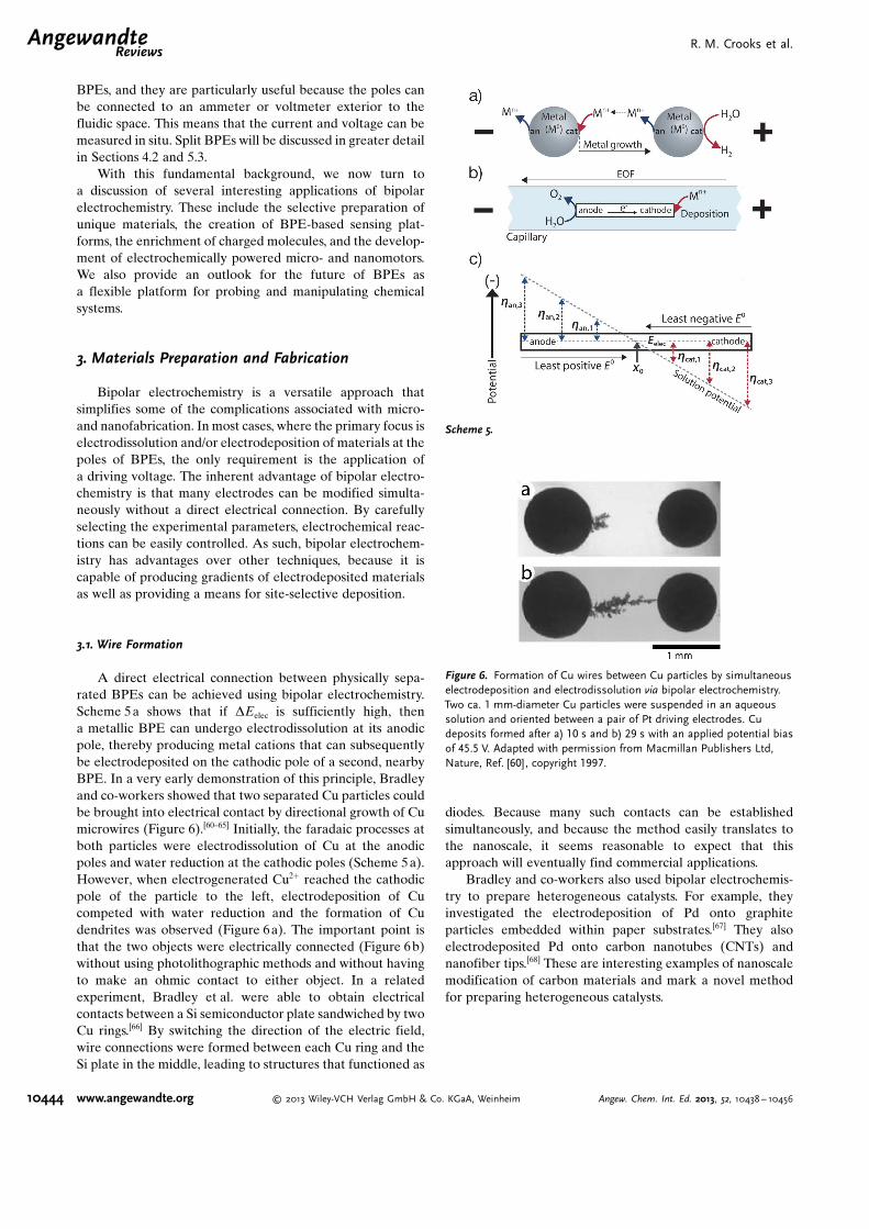
A direct electrical connection between physically sepa-rated BPEs can be achieved using bipolar electrochemistry.Scheme 5a shows that if DEelec is sufficiently high, thena metallic BPE can undergo electrodissolution at its anodicpole, thereby producing metal cations that can subsequentlybe electrodeposited on the cathodic pole of a second, nearbyBPE. In a very early demonstration of this principle, Bradleyand co-workers showed that two separated Cu particles couldbe brought into electrical contact by directional growth of Cumicrowires (Figure 6).[60–65] Initially, the faradaic processes atboth particles were electrodissolution of Cu at the anodicpoles and water reduction at the cathodic poles (Scheme 5a).However, when electrogenerated Cu2+ reached the cathodicpole of the particle to the left, electrodeposition of Cucompeted with water reduction and the formation of Cudendrites was observed (Figure 6a). The important point isthat the two objects were electrically connected (Figure 6b)without using photolithographic methods and without havingto make an ohmic contact to either object. In a relatedexperiment, Bradley et al. were able to obtain electricalcontacts between a Si semiconductor plate sandwiched by twoCu rings.[66] By switching the direction of the electric field,wire connections were formed between each Cu ring and theSi plate in the middle, leading to structures that functioned as
diodes. Because many such contacts can be establishedsimultaneously, and because the method easily translates tothe nanoscale, it seems reasonable to expect that thisapproach will eventually find commercial applications.
Bradley and co-workers also used bipolar electrochemis-try to prepare heterogeneous catalysts. For example, theyinvestigated the electrodeposition of Pd onto graphiteparticles embedded within paper substrates.[67] They alsoelectrodeposited Pd onto carbon nanotubes (CNTs) andnanofiber tips.[68] These are interesting examples of nanoscalemodification of carbon materials and mark a novel methodfor preparing heterogeneous catalysts.
Scheme 5.
Figure 6. Formation of Cu wires between Cu particles by simultaneouselectrodeposition and electrodissolution via bipolar electrochemistry.Two ca. 1 mm-diameter Cu particles were suspended in an aqueoussolution and oriented between a pair of Pt driving electrodes. Cudeposits formed after a) 10 s and b) 29 s with an applied potential biasof 45.5 V. Adapted with permission from Macmillan Publishers Ltd,Nature, Ref. [60], copyright 1997.
.AngewandteReviews
R. M. Crooks et al.
10444 www.angewandte.org � 2013 Wiley-VCH Verlag GmbH & Co. KGaA, Weinheim Angew. Chem. Int. Ed. 2013, 52, 10438 – 10456

3.2. Asymmetric Modification of Materials
Kuhn and co-workers have greatly expanded upon thepioneering electrodeposition studies of Bradley�s group. Forexample, they showed that electrochemistry could be carriedout on nanoscale BPEs. This is a significant advance because,according to Equation (1), bipolar electrodeposition ontonanoscale objects requires very high electric fields to achievea sufficient DEelec to drive electrochemical reactions. Kuhnsolved this problem by using a capillary electrophoresis (CE)setup to apply the field. The technique is called capillaryassisted bipolar electrodeposition (CABED). The experi-mental arrangement consists of a small-bore capillary filledwith an aqueous solution containing the CNTs and a salt ofthe metal to be deposited onto them (Scheme 5b).[69] Just as inCE, the ends of this capillary are placed into compartmentshousing driving electrodes connected to a high voltage powersupply. The resulting electric field leads to electroosmoticflow (EOF) from the anodic to the cathodic compartments. Inone example from Kuhn�s group, mobile CNTs acted as theBPEs, and as they moved toward the cathodic compartment,water was oxidized at their anodic poles and Au3+ wasreduced to Au0 at their cathodic poles. This resulted inelectrodeposition of Au at just one end of the CNTs(Figure 7). Other metals, including Cu and Ni, were also
electrodeposited using the same method, with the lattercomposite having magnetic properties.[70] Non-metallic mate-rials, such as conductive polymers, can also be deposited usingCABED.[71] For example, Janus-type objects were created byoxidizing pyrrole at one end of a CNT, to produce poly-(pyrrole), and reducing Cu2+ at the other end.
While Kuhn�s initial studies focused on capillary-basedtechniques, they showed that similar results could be achievedin simpler bipolar electrochemical cells. Specifically, thelimitation on the number of particles that could be modifiedin the capillary was alleviated by a clever cell design wherea pair of polymer or sintered glass membranes were employedto separate the BPEs and reactants from the driving electro-des and an inert electrolyte solution.[72] They demonstratedthe utility of this approach by electrodepositing Cu,[73] Au,[72]
and Pt[72] onto dispersions of carbon microtubes and glassy
carbon beads. Kuhn and co-workers also used this type of cellto modify carbon microbeads using an indirect electrochem-ical approach in which a pH gradient was generated at thepoles of a BPE to selectively precipitate inorganic andpolymeric layers.[74] For example, silica, TiO2, and electro-phoretic deposition paints were prepared site-selectivelyusing this method. Kuhn and co-workers have also demon-strated the bipolar electrodeposition of Prussian blue ongraphite rods, which can be used to generate luminolchemiluminescence.[75]
Bipolar electrochemistry can also be combined with othermethods to achieve interesting results. For instance, Nelsonand co-workers developed a technique, which they callfloating-electrode dielectrophoresis, for BPE-aided dielectro-phoretic assembly of CNTs.[76] Here, BPEs smooth the electricfield and allow for more precise and predictable deposition ofCNTs at desired locations.
3.3. Generation of Compositional Gradients
As mentioned earlier, the highest overpotentials aregenerated at the outermost edges of a BPE and they graduallydecrease until reaching x0 (Scheme 5c). It is possible to takeadvantage of this property of BPEs to prepare gradients ofmaterials. For example, Bjçrefors and co-workers showed thatgradients of thiol-based self-assembled monolayers (SAMs)could be prepared by controlled potential desorption ordeposition onto Au BPEs.[77] In this case, the surface densityof thiols is controlled by the variable interfacial potentialdifference along the BPE (Scheme 5c). The same group usedsurface plasmon resonance to show that electrochemicalgradients of [Fe(CN)6]
4� and [Fe(CN)6]3� could be prepared
in a solution in contact with a Au BPE (Figure 8).When two or more different electroactive materials
having different standard potentials (E8) are present insolution, a compositional gradient can be formed along thelength of a BPE. In this case, the materials having the least
Figure 7. Transmission electron micrograph of a 500 nm CNT and theasymmetric deposition of Au via CABED. The CNTs were placed ina 45 cm long capillary containing aqueous 1.0 mm HAuCl4. Upon theapplication of 30 kV, Au deposited at the cathodic pole of the CNT.Adapted with permission from Ref. [69]. Copyright 2008 AmericanChemical Society.
Figure 8. Surface plasmon resonance image of the gradient oxidationof [Fe(CN)6]
4� to [Fe(CN)6]3� at the anodic pole of a BPE as a function
of the indicated total currents. The voltage was applied througha 200 mm [Fe(CN)6]
4� solution via two stainless steel driving electro-des.
Bipolar ElectrochemistryAngewandte
Chemie
10445Angew. Chem. Int. Ed. 2013, 52, 10438 – 10456 � 2013 Wiley-VCH Verlag GmbH & Co. KGaA, Weinheim www.angewandte.org

negative E8 (requiring the least overpotential) are depositedclosest to x0, while those having the most negative E8(requiring the highest overpotential) are only deposited atthe ends of the BPE (Scheme 5 c). Shannon and Rama-krishnan demonstrated this principle by electrodepositinga compositional gradient of CdS on a Au BPE.[78] Thecomposition of the gradient was analyzed by surfaceenhanced Raman spectroscopy and found to be consistentwith the E8 values required to deposit the individualmaterials. In other words, the gradient was well-defined andpredictable. The same technique was used to synthesizegradients of Ag-Au alloys on stainless steel BPEs.[79]
Inagi, Fuchigami, and co-workers showed that conductiv-ity gradients of conductive polymers can be prepared onBPEs by position-dependent doping and undoping in non-aqueous solvents.[24, 25,80–82] For instance, a poly(3-methylthio-phene) (P3MT) film on an ITO support was anodically dopedwith PF6
� , changing its color from dark red to blue (Fig-ure 3a).[24] Other dopants (e.g., Cl�) and conductive polymers(e.g., poly(aniline) and poly(3,4-ethylenethiophene)) weremanipulated in a similar way,[25] more localized doping wasachieved by manipulating the experimental set-up,[81] andelectro-click reactions were also proposed for selectivemodification of electrode surfaces.[82]
4. Sensing and Screening Applications
4.1. Principles of BPE-based Sensing
BPEs have only recently been used as electroanalyticalsensors, probably because it is not easy to directly measure thecurrent flowing through them. However, our group recentlysolved this problem. Consequently, the advantages of usingBPEs for sensing and screening applications have becomemore compelling. Within the context of sensing and screening,these advantages include: 1) no direct electrical connection isrequired; 2) many electrodes can be controlled simultane-ously with a single DC power supply; 3) the sensing electro-des can have micron-scale, or even nanoscale, dimensions.
The basic operating principle of BPE sensing and screen-ing devices relies on electrical coupling between the sensingand the reporting poles (the reporting pole is the end of theBPE signaling the state of the sensing pole). In other words,the current passing through the two poles of the BPE must beequal (i.e., icat =�ian). For example, and as shown inScheme 6a, if the sensing reaction is an electrochemicalreduction, then the electrons required at the cathodic poleoriginate from a proportional oxidative reporting reaction atthe anodic pole. In the absence of the analytical target species,no oxidation occurs. Most reporting reactions that have beendiscussed in the literature are oxidations that generate aneasily observable optical signal at the anodic pole of a BPE.Optical readouts include ECL, fluorescence, and anodicdissolution (or change in refractive index) of a metal film.The advantage of these approaches is that they are easilyimplemented in parallel and are thus amenable to simulta-neous readout of large arrays of BPEs. When employing thesearrays, it is important to consider that sensing and screening
experiments typically require each electrode to act independ-ently of others, and therefore the amount of diffusion layeroverlap between electrodes and the extent of faradaicdepolarization should be minimized.
4.2. Amperometric Detection using Split Microband BPEs
It is also possible to directly measure the current passingthrough a BPE by inserting an ammeter between its poles(Scheme 6b). This method is useful for calibrating opticalsignals for a small number of BPEs, but it is impractical forlarge arrays because an ammeter would be required for eachelectrode. An early demonstration of directly measuring thecurrent flowing through a BPE was introduced by Nyholmand Klett, who used BPEs for amperometric detection inCE.[83] For this purpose, they used the split BPE configurationshown in Scheme 6b, which consists of two separated polesconnected external to the capillary with an ammeter. Bytaking advantage of the electric field inherent to CE, thisapproach avoids the need for a potentiostat. Note, this highfield is a nuisance when one tries to integrate traditionalthree-electrode electrochemical detection into CE.[84] Theauthors demonstrated that a split BPE produces resultssimilar to those obtained using cyclic voltammetry. Nyholmand co-workers later expanded this work to include an arrayof 20 Au microbands so that analytes with different E8 valuescould be detected simultaneously.[85]
4.3. Sensing and Reporting by ECL at a Single BPE Pole
To avoid making a direct electrical contact to the BPE,Manz and co-workers introduced ECL as an optical signaltransduction method (Scheme 6 c).[45] Briefly, ECL occurswhen an excited state molecule, generated from a series of
Scheme 6.
.AngewandteReviews
R. M. Crooks et al.
10446 www.angewandte.org � 2013 Wiley-VCH Verlag GmbH & Co. KGaA, Weinheim Angew. Chem. Int. Ed. 2013, 52, 10438 – 10456

charge-transfer reactions, relaxes to the ground state andemits a photon.[86] ECL is highly sensitive, with near zero-background signal, because no excitation light source isrequired to drive it. One of the most effective and widely usedECL reactions involves the co-oxidation of tris(bipyridine)r-uthenium(II) ([Ru(bpy)3]
2+) and tri-n-propylamine (TPrA).Manz and co-workers used this type of ECL reaction to detect[Ru(phen)3]
2+ and [Ru(bpy)3]2+ following electrophoretic
separation. In this case, TPrA was present in the separationcolumn, and the electric field required for CE separationsenergized the BPE. When both detection and readout occurat the same pole of the BPE, as in this example, then theaccessible analytes are limited to species that participate orcompete with the ECL-producing reaction. A competitionreaction was recently demonstrated in which mRNA sequen-ces associated with breast cancer cells displaced a secondstrand labeled with a [Ru(bpy)3]
2+-laden silica particleresulting in a reduction in ECL intensity.[87]
4.4. Electrically Coupled Sensing using ECL
Our group introduced a sensing scheme in which thereporting and sensing reactions occur on different poles. Theimportant innovation here is that the sensing and reportingpoles are decoupled, but their electrochemical relationship ispreserved via conservation of charge (Scheme 6). This newapproach eliminated the previous requirement that analytesbe capable of direct participation in the ECL reactionsequence, and hence opened the door to BPE sensing ofa wide variety of analytes.
In our initial study, we showed that the detection of benzylviologen (BV2+) at the BPE cathode was electrically coupledto ECL emission occurring at the anode (Scheme 6 c). More-over, the effect of electrode length and geometry on ECLemission were investigated.[34] With Duval�s work as a foun-dation, we described a semi-empirical approach for predictingEelec, in addition to DEelec as a function of Etot, and we showedthat the intensity of ECL emission can be directly correlatedto the magnitude of current flowing through the BPE.[36]
During a sensing or screening experiment using BPEs asillustrated in Scheme 6, which we refer to as “open” BPEs, itis critical that each electrode experiences a uniform electricfield. As alluded to earlier, this means that only a smallfraction of the total current, typically less than 1%, ispermitted to pass through the BPE with the remaindertraversing the solution as an ionic flux (Scheme 3b).[36] ClosedBPEs do not have this requirement because the only path forcurrent flow between driving electrodes is via electrontransfer through the BPEs (Scheme 4).
On the basis of these simple operating principles, BPEsensors have been employed to detect myriad analytes. Forexample, our group demonstrated a DNA sensor with ECLreadout following a design similar to that shown in Sche-me 6c, except the cathodic pole of a Au BPE was modifiedwith a thiol-terminated probe single-stranded DNA (ssDNA)sequence.[35] In a control experiment, with Etot = 22.0 V, noECL was observed because DEelec was insufficient to drivesignificant faradaic reactions at the modified Au BPE.
However, when the target ssDNA labeled with a Pt nano-particle (NP) hybridized with the electrode, Etot = 22.0 V wassufficient to drive the oxygen reduction reaction (ORR) atthe Pt NP surface. The lowering of the required hcat, and thusDEelec, by the Pt catalyst then activated ECL emission at theanode. This experiment also clearly demonstrated a basicprinciple of many BPE sensing platforms: the sensingreaction must facilitate or catalyze a reaction to enhancethe current flowing through the BPE.
As previously mentioned, one of the main virtues ofbipolar electrochemistry is that many BPEs can be drivensimultaneously using a single power supply and two drivingelectrodes. Figure 1a is an optical micrograph of a device thatincorporates 1000BPEs.[16] When a sufficiently high Etot isapplied through the two driving electrodes spanning the array,red ECL emission is observed at the anode of each of theelectrodes (Figure 1b). As shown in Figure 1c, the config-uration of this device is extremely simple. The most importantdesign rule for large arrays of this sort is that the potentialdropped over each electrode (DEelec) be the same. In thepresent case, this is demonstrated by the remarkable uni-formity of the ECL line scans shown in Figure 1d. In thisparticular experiment, no sensing chemistry was placed on thecathodic poles of the BPEs, but clearly this can be accom-plished using a robotic spotter, as we will discuss later inSection 4.6, to yield massively parallel sensing arrays.
In some cases, the solution conditions required for sensingand reporting reactions may be incompatible with one-another, and hence it is necessary to place the anodic andcathodic poles of the electrodes into spatially isolatedcompartments. To address this requirement, we developeda bipolar electrochemical cell in which a BPE, or multipleBPEs, span two microchannels.[43] When the same Etot isapplied across the two channels, the sensing and reportingreactions are electrically coupled through the BPE but remainotherwise separated. This approach has been used to followECL emission coupled to the reduction of [Fe(CN)6]
3�, whichcan be used for the indirect detection of glycated hemoglo-bin.[43] Chen and co-workers recently used a similar two-channel design to detect prostate-specific antigen (PSA). Intheir approach, PSA guides the deposition of Ag NPs to thespace between two microbands. Eventually the two micro-bands become electrically connected, and the resulting BPEhas sufficient length to generated ECL at the applied value ofEtot.
[88]
Interestingly, new functionality has been introduced toECL reporting by changing either the electrochemical cell orthe shape of the BPE. In the former case, we showed thatwhen a single BPE is present at the intersection of twomicrochannels, four driving electrodes can be used to controlthe electric field in such a way that electrochemical reactionscan be localized at specific points on the BPE surface.[40] Inthe latter case, the shape of the BPE was changed froma simple rectangle to a triangle. A single triangle acts just likean array of individual BPEs having different lengths, whichmeans that each location on the edge of a triangular BPEexperiences a different overpotential. Hence, a single lumi-nescence micrograph can be used to extract kinetic informa-tion using a technique we call “snapshot voltammetry”.[39] We
Bipolar ElectrochemistryAngewandte
Chemie
10447Angew. Chem. Int. Ed. 2013, 52, 10438 – 10456 � 2013 Wiley-VCH Verlag GmbH & Co. KGaA, Weinheim www.angewandte.org

have also shown that multiple channels and BPEs can beconfigured to yield logic functions like NOR, OR, and NANDwith optical readout.[37, 89] These could eventually be useful forsensing and signaling applications. Foret, Manz, and co-workers recently demonstrated that floating Au platelets canact as BPEs in a CE separation, where ECL might be used tofollow a cathodic sensing reaction.[90] The important result isthat the platelets are easily replaced because they move in theseparation volume.
4.5. Detection using the Anodic Dissolution of a Metal Film
In addition to ECL readout, our group has pioneered theuse of metal film electrodissolution as a reporting reaction forbipolar electrochemistry.[38] When Etot is applied, the electro-dissolution of thermally deposited Ag is electrically coupledto a reduction reaction occurring at the cathodic pole of theBPE (Scheme 6d). Because han is highest at the extreme edgeof the BPE anode, Ag first begins to dissolve at the distal edgeof the electrode and then continues to dissolve toward x0. Thedissolution will continue until it reaches a critical point, whereDEelec cannot drive the two types of faradaic processes. Thisapproach has a number of advantages over the ECL signalingmethod. First, it eliminates the need for detection of light,because the change in length of the electrode can be read withthe naked eye. Second, it eliminates the need for solution-phase reagents like [Ru(bpy)3]
2+. Third, the amount of chargestored in the Ag as a function of its length depends only on thethickness of the film, and therefore a very broad dynamicrange of sensitivities is available for sensing applications.Fourth, Ag dissolution is associated with a single redoxprocess, whereas ECL relies on two redox processes whichcan compromise the limit of detection for sensing applica-tions.[36]
We demonstrated the idea of using the Ag electrodisso-lution reaction for chemical sensing by immobilizing a probessDNA sequence on the cathodic pole of a BPE.[38] Whena target sequence labeled with horseradish peroxidase (HRP)hybridized to the probe, the HRP catalyzed the reduction ofH2O2 to water via a mediator. The presence of the mediator,and hence the ssDNA target, was then signaled by a change inthe length of the Ag thin film at the anodic pole of the BPE. Inthe absence of the target, no change was observed.
Interestingly, a BPE can be activated without any externalpower source. This type of device, which is shown inFigure 9a, is powered by a phenomenon called streamingpotential, which is essentially the opposite of electroosmosisbecause it is initiated by simply pushing an electrolytesolution through a microchannel having charged walls.[41]
Streaming potentials used for the experiment shown inFigure 9 resulted from the movement of counterions in theelectrical double layer at the interface between the electrolytesolution and the charged walls of a poly(dimethylsiloxane)(PDMS)/glass microchannel. When the resistivity of theelectrolyte solution is kept high (�MWcm�1), streamingpotentials of up to 8 V can be achieved. As a proof of concept,benzoquinone was detected using Ag electrodissolution asa reporting mechanism (Figure 9b,c). By eliminating the need
for a power source, this type of detection scheme opens up thepossibility to perform point-of-care sensing applications inresource-limited settings.
4.6. Electrocatalyst Screening
In addition to using metal film dissolution for sensingapplications, it can also be used for the rapid screening ofelectrocatalysts. In one recent example from our group, thecathodic poles of an array of BPEs were spotted with catalystcandidates for the ORR.[42] When a voltage was applied acrossthe array by a pair of driving electrodes, electrodissolution ofAg microbands was initiated. The key point is that thenumber of bands dissolved depends on the efficiency of theassociated electrocatalyst. This concept is illustrated sche-matically in Figure 10.
This method relies on the fact that the overpotentialbetween the BPE and the solution varies laterally along theBPE (Scheme 5c). The most effective electrocatalyst requiresthe lowest DEelec for dissolution of Ag, and therefore, theoverall length of the BPE associated with that catalyst will bethe shortest at equilibrium. In other words, as the bands beginto dissolve, the effective length of the electrode (lelec)decreases, which in turn decreases DEelec [Eq. (1)]. Thebands stop dissolving once this driving force becomesinsufficient to simultaneously drive Ag oxidation and theORR. Figure 10 c shows the screening device prior to theapplication of Etot and Figure 10d shows the result of theexperiment. The readout of this device is simple: the more Agbands that dissolve, the better the electrocatalyst. We haverecently expanded and improved our BPE electrocatalystscreening platform by increasing the size of the array by anorder of magnitude, changing the identity of the anodicreporter to Cr (which oxidizes near the thermodynamicpotential of the ORR), and implementing piezodispensing asa method of introducing compositionally varied electrocata-lyst candidates.[44] This setup was used to evaluate threebimetallic systems for the ORR: Pd-Au, Pd-Co, and Pd-W.
Figure 9. a) Optical micrograph of a microfluidic channel that incorpo-rates a split BPE for streaming potential experiments. The channel was6 mm long and the BPE consisted of two Au microbands makinglelec = 4.5 mm. b) An optical micrograph of the BPE anode, which wasmodified with a 20 nm thick layer of Ag over 5 nm of Cr. The channelcontained an aqueous 1.0 mm benzoquinone solution. At t = 0 s, thetwo poles of the BPE were connected externally. c) After 1400 s, the Agfilm was completely oxidized. Adapted with permission from Ref. [41].Copyright 2011 American Chemical Society.
.AngewandteReviews
R. M. Crooks et al.
10448 www.angewandte.org � 2013 Wiley-VCH Verlag GmbH & Co. KGaA, Weinheim Angew. Chem. Int. Ed. 2013, 52, 10438 – 10456

Following our original work relating to catalyst screeningusing open BPEs, two interesting reports recently appeareddescribing similar results but using closed BPEs. In the firstexample, several Pt nanomaterials were dropcast onto glassycarbon electrodes that were placed into cells containing air-saturated 0.5m H2SO4. The electrodes were electricallyconnected to Pt microdisk electrodes immersed in a solutioncontaining the ECL reactants. Using this setup, Chen and co-workers report that the ECL at the Pt microdisks is directlycorrelated to the ORR occurring at the Pt catalyst candidates,which provides a simple means for high throughput screen-ing.[91] In the second example, Zhang and co-workers intro-duced a method they call fluorescence enabled electrochem-ical microscopy (FEEM).[92] In this experiment, they preparedlarge arrays of micron-scale carbon-fiber (CF) BPEs, and thenpatterned Pt films on one side of this array using bipolarelectrodeposition. During the screening experiment, the Pt-modified BPE anodes catalyzed the oxidation of H2O2 to O2,while a non-fluorescent species was reduced to a fluorescentspecies at the BPE cathode. In regions of the array notpatterned with Pt, no fluorescence was observed. Thisapproach shows great promise for large-scale, electrochem-ical imaging.
5. Bipolar Electrode Focusing
5.1. Principles of BPE Focusing
Due to small sample volumes and low absolute numbersof molecules present within microfluidic devices, the detec-tion of analytes in such systems often requires a preconcen-tration step prior to analysis. Our group, together with ourcollaborators Prof. Ulrich Tallarek and Dr. Dzmitry Hlush-kou from Philipps-Universit�t Marburg in Germany, haveshown that BPEs can be employed to address this issue byenriching charged analytes along a locally generated electricfield gradient.[93] We call this method BPE focusing, and it isa member of a family of analyte enrichment techniques basedon the principle of electrokinetic equilibrium. More specifi-cally, BPE focusing is a counter-flow gradient focusingtechnique in which charged analytes enrich when electro-migration (EM) is balanced against convection.[94]
The key to this technique involves generation of a localelectric field gradient near a BPE. When a sufficiently highpotential bias is applied across a microchannel having anembedded BPE (Scheme 7 a), water electrolysis may proceedat the BPE poles following Equations (2) and (3), respec-
2 H2OÐ O2 þ 4 Hþ þ 4 e� ð2Þ
2 H2Oþ 2 e� Ð H2 þ 2 OH� ð3Þ
tively.
TrisHþ þOH� Ð TrisþH2O ð4Þ
For anionic enrichment, electrogenerated OH� at the BPEcathode (Scheme 7b) may neutralize a positively chargedbuffer cation, such as the protonated form of tris(hydrox-
Figure 10. a) Top: schematic illustration of three BPEs having differentelectrocatalyst candidates for the ORR immobilized on their cathodicpoles. The functional anodes of the BPEs consist of an array of 25 Agmicrobands. The red line indicates the potential, which is initiallyuniform, dropped over each electrode. Bottom: When Etot is appliedand some Ag bands dissolve, the effective length of each BPEdecreases. This results in a lowering of DEelec until it reaches a valuethat is insufficient to drive additional faradaic reactions. b) Side viewof one BPE showing the electrochemical processes at the anodic andcathodic poles. c) Optical micrograph of an array of three BPEsmodified with the indicated catalyst candidates prior to application ofEtot. The ITO support has been outlined using the gray dashed lines.d) Optical micrograph of the same BPE array after application of Etot.The change in the number of Ag microbands reveals the relativeactivity of each catalyst candidate. Adapted with permission fromRef. [42]. Copyright 2012 American Chemical Society.
Scheme 7.
Bipolar ElectrochemistryAngewandte
Chemie
10449Angew. Chem. Int. Ed. 2013, 52, 10438 – 10456 � 2013 Wiley-VCH Verlag GmbH & Co. KGaA, Weinheim www.angewandte.org

ymethyl)aminomethane (TrisH+) [Eq. (4)], therebyforming an ion depletion zone near the BPE. Theincreased solution resistivity within the ion depletionzone causes a large proportion of Etot to be droppedin this region. It is this electric field gradient thatallows the local enrichment of analyte in thepresence of a counter-flow.
This local electric field gradient does not appearin the systems previously discussed in this review,because in those cases the system is designed toensure that only a small fraction of the total currentpasses through the BPE. However, by simply low-ering the electrolyte concentration in the micro-channel, most of the current can be forced throughthe BPE. This concept can be easily understood interms of Scheme 3b. For enrichment experiments ina single microchannel, RS2 is kept high, therebydiverting the current through Relec. Other groupshave also reported the use of BPEs for enrichmentby either generating pH gradients or non-uniformEOF.[95, 96]
5.2. Electrokinetics and Mass Transport
The transport of charged analytes during a BPEfocusing experiment is controlled by convection andEM. A cathodic EOF develops when a potential biasis applied across the negatively charged walls ofa PDMS/glass microchannel. In addition to EOF,bulk solution flow can be controlled in eitherdirection by pressure-driven flow (PDF), which isinitiated by creating a solution height differential in thereservoirs at the channel ends by simply adding or removingsolution.
The electrophoretic (EP) velocity of a charged analyte(uep) in an electric field is dictated by Equation (5), where mep
uep ¼ mepV l ð5Þ
is the EP mobility and Vl is the local electric field strength.
Consequently, as anions enter the microchannel and approachthe BPE, they experience an increasing uep as the electric fieldstrength increases. Enrichment occurs when the velocities dueto EM and convection are equal in magnitude and opposite indirection (Scheme 7c). Because the location of enrichmentdepends on mep [Eq. (5)], analytes having different EPmobilities may be simultaneously separated and enriched atdifferent locations in the channel. Figure 11a shows theseparation and enrichment of three negatively charged tracershaving different mep as a plot of enrichment factor (EF, ratio ofthe concentration in the enriched band to the initial concen-tration) vs. distance from the BPE.[26]
5.3. Guidelines for Enrichment
The formation and stability of the electric field gradientnear a BPE has been investigated in several fundamental
studies. For example, we measured the current flowingthrough a split BPE to show that a significant change to thelocal electric field gradient results only after a large percent-age (ca. 80 %) of the total current passes through the BPE(Scheme 3b).[27] In other words, only when there is a signifi-cant degree of faradaic depolarization is a locally enhancedelectric field observed. There are three additional aspects ofBPE focusing worth mentioning here. First, split and con-tinuous BPEs lead to local electric fields having similarcharacteristics, and hence result in the same degree ofenrichment (Figure 11 b).[27] Second, an array of microbandelectrodes embedded within a microchannel can be used todirectly measure the axial electric field, and this type ofexperiment (Figure 11c) confirms the shape of the localelectric field illustrated in Scheme 7c. Third, the electric fieldgradient has been shown to be stable for> 2.5 h.[28, 29]
To better understand the interplay between forces neces-sary for BPE focusing, our collaborators have performedsimulations,[26–28, 93, 97,98] and we have used these to optimize theextent and rate of enrichment. As a general guiding principle,steeper electric field gradients lead to more compact andhighly enriched bands, although shallower gradients arebetter for separating mixtures of charged analytes. Steepergradients are achieved by using higher ionic strength buffers,because this leads to a larger difference in electrolyteconcentration between the ion depletion zone and the bulkconcentration of the buffer. As discussed earlier, however,
Figure 11. a) Plot of enrichment factor vs. axial distance from the BPE cathodeshowing the enrichment and separation of BODIPY2�, MPTS3�, and PTS4� in5.0 mm TrisH+ with Etot = 40.0 V in a 12 mm-long, Pluronic-coated channel.Adapted with permission from Ref. [26]. Copyright 2009 American ChemicalSociety. b) Comparison of the enrichment factor as a function of time forBODIPY2� at split and continuous BPEs with Etot = 35.0 V in 5.0 mm TrisH+.Adapted with permission from Ref. [27]. Copyright 2009 American ChemicalSociety. c) Experimentally determined local axial electric field strength as a functionof position and time with Etot = 35.0 V in 5.0 mm TrisH+. Adapted with permissionfrom Ref. [28]. Copyright 2011 The Royal Society of Chemistry. d) Plot of enrich-ment factor vs. time for 10.0 pm (circles) and 1.0 nm (triangles) BODIPY2� inpH 8.1, 100 mm TrisH+. Initially, Etot = 200 V, but it was periodically raised at theindicated times. Adapted with permission from Ref. [29]. Copyright 2011 AmericanChemical Society.
.AngewandteReviews
R. M. Crooks et al.
10450 www.angewandte.org � 2013 Wiley-VCH Verlag GmbH & Co. KGaA, Weinheim Angew. Chem. Int. Ed. 2013, 52, 10438 – 10456

lowering RS decreases the current flowing through the BPE,which adversely affects the ion depletion zone. Fortunately,this seeming contradiction can be resolved by reducing thecross-sectional area of the fluidic channel.[29] The bottom lineis that high buffer concentrations and small cross-sectionalareas lead to EFs of > 500 000 (Figure 11d).[29]
Another important fact about BPE focusing is that lowerinitial analyte concentrations typically lead to higher EFs.This is because enrichment of the analyte occurs within theion depletion layer, and because the analyte itself is a chargecarrier it increases the local conductivity of the solution. Asthe concentration of the enriched band approaches that of thebackground buffer, enrichment ceases.[97]
Although many analytical methods have been describedin the literature for enriching anions, far fewer are availablefor cations. This is because cationic enrichment often requiresan anodic EOF. BPE focusing can be adapted to enrichcations by coating the microchannel walls with a positivelycharged polymer, thereby reversing the direction of EOFfrom cathodic to anodic.[33] In addition, the positively chargedbuffer used for anion enrichment must be replaced with onethat is negatively charged such as HCO3
� . The latter isneutralized by H+ produced at the BPE anode, and thereforeenrichment of cations occurs at the anodic pole of the BPE,rather than at the cathodic pole.[33]
5.4. Applications of BPE Focusing
Beyond enrichment and separation, we have also shownthat manipulating the local electric field gradient with a BPEis useful for a variety of other applications.[30] For example, itcan be used to concentrate and direct the flow of chargedanalytes.[32] As previously discussed, enrichment occurs whenEM balances convection. This means that the forwardmovement of an analyte ceases when its EP velocity isgreater than or equal to the opposing convective velocity.Using these principles, we have demonstrated the controlledtransport and selective delivery of two charged analytes byemploying a microfluidic design having two microband BPEsembedded near the split of a Y-shaped microchannel(Scheme 8). In this configuration, the BPEs act as on/offswitches for an electric field gradient. Specifically, when bothBPEs are activated using an external switch, the local electricfield strength is high and the analytes enrich and separate inthe main channel (Scheme 8a) as discussed earlier in thecontext of Figure 11 a. Then, when one BPE is disconnectedand the PDF is increased from right to left (Scheme 8b), bothenriched bands move toward the intersection. By carefullycontrolling when the gating BPEs are active, the anionicfluorescent tracer closest to the intersection (BODIPY2�,represented by the black ball) is delivered into the lowersecondary channel. This occurs because the local electric fieldin this region of the channel has been lowered, leading toa lower EP velocity and the dominance of PDF. After thisdelivery, the first BPE is reconnected and the second one isdisconnected, thus allowing the other fluorescent tracer(MPTS3�), represented by the gray ball, to be delivered intothe upper secondary channel by PDF (Scheme 8c).
5.5. Dual-Channel BPE Focusing
Thus far, we have only discussed BPE focusing studies inwhich the BPE is embedded within a single channel (Sche-me 7a and 8). Recently, however, we have shown that thereare some compelling reasons to consider the dual-channelconfiguration illustrated in Scheme 9a.[29,31] The basic operat-ing principles of the dual-channel approach are analogous tothose of a single-channel device. Specifically, DEelec must
Scheme 8.
Scheme 9.
Bipolar ElectrochemistryAngewandte
Chemie
10451Angew. Chem. Int. Ed. 2013, 52, 10438 – 10456 � 2013 Wiley-VCH Verlag GmbH & Co. KGaA, Weinheim www.angewandte.org

exceed the potential required for water oxidation andreduction. If this condition is met, water oxidation [Eq. (2)]will lead to H+ formation at the anodic pole of the BPE in thebottom channel, while water reduction [Eq. (3)] generatesOH� at the cathodic pole in the top channel. If anappropriately charged buffer capable of being neutralizedby the products of water electrolysis is placed in eitherchannel, an ion depletion zone, and thus an electric fieldgradient, results. For example, in the top channel, TrisH+ maybe neutralized by OH� , or, in the bottom channel, acetatebuffer may be neutralized by H+ (Scheme 9b) to produce anelectric field gradient that is suitable for enrichment.
Using the dual-channel device, we have achieved EFs ofup to 142000-fold at rates as high as 71-fold/s. These excellentfigures of merit are achievable because this configurationdecouples Etot and DEelec. This means that higher values of Etot
may be applied without generating gas bubbles at the BPE.Moreover, higher Etot values increase the rate at which theanalyte is transported from the channel reservoirs to theenrichment zone, while simultaneously steepening the localelectric field gradient. As discussed in Section 5.3, the lattersituation leads to a narrower and more highly enrichedanalyte band.
A combination of interesting electric field gradients andmass transport conditions can be achieved using the dual-channel configuration, and one of these is illustrated inFigure 12 a. This type of gradient results in the simultaneousseparation and enrichment of anions and cations in the
bottom channel. Here, PDF is directed from left to right,while the direction of EM depends on the charge on thetracer. At the channel center, where there is no electric fieldstrength, ions experience no EM; therefore, their net velocityis dictated exclusively by convection. To the left of the BPEanode, anions move toward the channel center by both EMand PDF. In the same region, cations also experience PDFtoward the channel center, but EM is in the oppositedirection. When the forces of EM and PDF balance oneanother, the net velocity of the cations is zero and they enrich.An analogous argument applies to the right side of the BPEanode for anion enrichment. For example, in Figure 12b PDFis directed from left to right in the bottom channel. To the leftof the BPE anode (indicated by dashed lines), [Ru(bpy)3]
2+
enriches while BODIPY2� enriches to its right. This fluores-cence micrograph was collected using a filter set capable ofdetecting both BODIPY2� and [Ru(bpy)3]
2+. Three secondsafter Figure 12 b was collected, another fluorescence micro-graph (Figure 12 c) was recorded using a filter set that onlydetects BODIPY2�. In this micrograph, only BODIPY2�
enrichment is observed, thereby confirming the identity ofthe two enriched bands.
Finally, we have very recently shown that a dual-channelBPE configuration can be used to partially desalinate sea-water.[125] In this case, Cl� , present at high concentration inseawater, is oxidized to neutral Cl2 at the BPE anode. Thislocal reduction in the number of ions results in an electricfield gradient that shunts other ions into a nearby thirdchannel. Using this approach, it is possible to remove ca. 25%of the ions from seawater with high energy efficiency. Recentsimulations suggest that slight changes to the experimentalconfiguration could lead to a much higher degree ofdesalination.
6. Microswimmers
In recent years there have been a number of trulyremarkable reports of mobile BPEs, sometimes called micro-swimmers, that exhibit a function not so different from theminiature submarine in the classic 1966 movie “FantasticVoyage”.[20] Mobility is possible because of one of the keyattributes of BPEs mentioned in Section 2: no externalconnection is required for their operation. Particular func-tions of mobile BPEs are achieved by changing the compo-sition of the BPE itself, the solution, or the applied electricfield. Though the idea of autonomous moving objects andmotors has been discussed for many years, recent develop-ments using BPEs have provided a means for implementa-tion.[20]
6.1. Self-Powered, Mobile BPEs
Mallouk, Sen, and co-workers were the first to use self-powered BPEs as nanomotors.[17] The early nanomotors werebimetallic rods having lengths of ca. 1 mm and diameters of ca.400 nm with different metals, such as Au and Pt,[17] at theirends. Initially, it was believed that the motion of the rods was
Figure 12. a) Schematic illustration showing the direction of convec-tion, EM, and the net velocity of tracers in the bottom channel ofa two-channel microfluidic device. b) Fluorescence micrograph,obtained using a filter set capable of detecting both tracers, showingthe location of the enriched bands of BODIPY2� and [Ru(bpy)3]
2+ inthe bottom channel. The location of the BPE is indicated by dashedwhite lines and the dotted gray lines show the microchannel walls.Etot = 30 V was applied to the positive reservoir (Scheme 9) and theothers were at ground. The solution was 40.0 mm acetate buffer.c) Fluorescence micrograph collected 3 s after (b) using a filter setsensitive only to BODIPY2�. Adapted with permission from Ref. [31].Copyright 2012 The Royal Society of Chemistry.
.AngewandteReviews
R. M. Crooks et al.
10452 www.angewandte.org � 2013 Wiley-VCH Verlag GmbH & Co. KGaA, Weinheim Angew. Chem. Int. Ed. 2013, 52, 10438 – 10456

due to the evolution of O2, arising from the catalyticdecomposition of H2O2 at the Pt end. This was thought todisturb the interfacial tension of the water near the rods,causing them to move in the direction of the Pt end.[17, 18,99–102]
However, the movement of the nanorods was later attributedto bipolar electrochemistry.[103] The basic idea is that electronsgenerated from the electrocatalytic oxidation of H2O2 at theanodic pole are used for a reduction reaction, such as theORR, at the cathodic pole. This hypothesis was confirmed bysynthesizing a series of nanorods consisting of various metalshaving different electrocatalytic properties.[103] Moreover, theaddition of an insulating layer between the anodic andcathodic poles of the BPE blocked the flow of electrons andrendered the nanorods immobile. Finally, by introducingmagnetic segments to the nanorods, the direction of theirmotion could be controlled, thereby enhancing their techno-logical versatility.[18]
Wang and co-workers have also played an important rolein the field of BPE nanomotors.[19] They reported improvedefficiencies and achieved speeds of 94 mms�1 by introducingCNTs to the Pt end and adding hydrazine to the solution.[104]
By incorporating other metal pairs and alloys, speeds could befurther enhanced.[105, 106] Wang and co-workers also reportedthat mobile BPEs could be used for sensors. For example, theydetected Ag+ in a H2O2 solution using Au-Pt nanomotors.[107]
This function arises, because Ag+ is easier to reduce than O2.The same group later reported similar methods for thecapture and isolation of biologically relevant species (e.g.cancer cells, DNA, and RNA),[108–110] oil droplets in water,[111]
and other species.[112, 113] They used nanomotors to “write” ona surfaces.[114]
6.2. BPE Swimmers Powered by an External Electric Field
Kuhn and Loget used bipolar electrochemistry for thedirected linear motion of metallic objects by a process theycalled self-regeneration.[115] This approach is based on thesimultaneous dissolution of a BPE at its anodic pole andsubsequent deposition of the same metal onto the cathodicpole in an externally applied electric field. Conceptually, theprinciple is similar to that reported earlier by Bradley and co-workers (Scheme 5a and 10 a).[60] In the present case, a ZnBPE filament produced in a capillary was electrochemicallydissolved at the anodic pole and redeposited at the cathodicpole. This resulted in an effective speed of ca. 60 mms�1
(Figure 13).In addition to self-regeneration, other bipolar electro-
chemical processes can also trigger BPE movement in anelectric field. For example, Kuhn and Loget designeda method for linear and rotational movement of BPEs insolution.[21] In this case, the BPE—a metallic bead—movesdue to the formation of O2 and H2 bubbles arising from wateroxidation and hydrogen evolution, respectively, at oppositesides of the sphere (Scheme 10 b and Figure 2a). Because thevolume of H2 produced is twice as high as the amount of O2,the BPE is propelled toward the negative driving electrode.The speed of the BPE could be increased by suppressing O2
evolution at the anodic pole, which reduces the degree of
thrust arising from O2 bubbles (Figure 2b).[21] This wasaccomplished by adding hydroquinone, which is more easilyoxidized than water, to the solution. Kuhn and co-workersused this same approach to achieve vertical and horizontalrotation of a BPE by modifying its shape,[21] as well as verticalmovement of the BPEs in capillaries.[22]
As discussed in Section 3.2, the same group was able toproduce Janus-type carbon microtube BPEs modified with Ptat just one pole. These BPEs were later used as micro-swimmers, which were propelled by H2O2 decomposition atthe Pt end.[116] Linear and rotational movement of themicroswimmers was also possible by controlling the place-ment of the Pt deposition on the BPE, and their motion couldbe turned off and on by manipulation of the external electricfield.[117]
Sojic, Kuhn, and co-workers also demonstrated that BPEswimmers are capable of generating ECL emission when theoxidation that triggers ECL is coupled to water reduction atthe cathodic pole of a carbon bead BPE.[23] Along these samelines, Kuhn, Bouffier, and co-workers showed that BPEs canoperate as a wireless electrochemical globe valve, whereelectrogenerated H2 bubbles cause the valve to lift andopen.[118]
Scheme 10.
Figure 13. Optical micrographs as a function of time illustrating theconcept of self-regeneration. A Zn wire was formed at an electrode byelectrodeposition of Zn2+ inside a glass capillary. The Zn wire wasfreed by removing the electrode from the solution. Etot = 125 V wasapplied between driving electrodes at the ends of the capillary. Thisresulted in oxidation of Zn at the BPE anode and deposition at itscathode. This process results in apparent movement of the Zn wire.Reprinted with permission from Ref. [115]. Copyright 2010 AmericanChemical Society.
Bipolar ElectrochemistryAngewandte
Chemie
10453Angew. Chem. Int. Ed. 2013, 52, 10438 – 10456 � 2013 Wiley-VCH Verlag GmbH & Co. KGaA, Weinheim www.angewandte.org

7. Summary and Outlook
The objective of this Review is to stimulate additionalinterest in bipolar electrochemistry, especially in subdisci-plines of science that are able to utilize its particularcharacteristics. The latter are represented by the examplesin the foregoing discussion, but the principal attribute is thatBPEs can be activated in the absence of an ohmic contact.The low cost, ease of operation, and simple instrumentationrequired for bipolar electrochemistry have their origin in thiswireless-contact principle.
One consequence of wireless operation, which our groupintroduced several years ago, is that thousands of electrodescan be controlled simultaneously (Figure 1) with just a batteryor a DC power supply. Looking to the future, it seems obviousthat BPEs will find more applications to chemical andbiological sensing due to the extreme simplicity of themethod. For example, we are presently investigating theintegration of BPEs into low-cost paper microfluidic devi-ces[119] for point-of-care applications and other situations inwhich complicated instrumentation is not desirable.[120, 121]
The quick and simple screening capabilities of BPEs,which were discussed in Section 4.6 in the context of electro-catalysis, will also be adapted to other types of screening andselection processes in the future. For example, applications toDNA, protein, and glycan arrays are certainly worth inves-tigating. A specific case in which BPEs could possibly providebenefit is enabling the type of site-selective electrochemicalreaction screening method used by Moeller and co-work-ers.[122]
The principle of wireless contact also makes it possible tocarry out electrochemical experiments on mobile electrodes.The potential of these microswimmers are embodied in thework of Mallouk, Sen, Kuhn, and Wang discussed earlier, butwe believe that many more interesting applications willevolve in future years in the fields of medicine, electronics,and chemical sensing. For example, one could imagine self-assembling electronic circuits using this approach, or perhapssearch a solution for a small number of target molecules.
As discussed in the Review, Kuhn and others havepioneered applications of BPEs to materials science andmaterials chemistry, and it is very likely that even moresignificant types of structures and synthetic approaches, whichare difficult or impossible to prepare by other means, are justaround the corner.
Another surprising fact is that bipolar electrochemistryplays a key role in certain widespread applications, eventhough the bipolar contribution has only recently beendiscovered. For example, Amatore and co-workers haveshown that bipolar electrochemistry is associated with feed-back behavior in scanning electrochemical microscopy(SECM).[123] Of even more significance, Zhang and hiscolleagues demonstrated that the behavior of the types ofcarbon fiber electrodes used to study biological cells are oftendominated by bipolar electrochemical principles.[58] No doubtthere are other examples like these in which the hidden handof BPEs will eventually be revealed.
Glossary and Symbols
BPE bipolar electrodeCNT carbon nanotubeCE capillary electrophoresisE8 standard potentialDEelec potential difference between the bipolar
electrode polesEelec potential of the floating bipolar electrodeEtot externally applied potential bias between
driving electrodesECL electrogenerated chemiluminescenceEOF electroosmotic flowEM electromigrationEF enrichment factorlelec length of the bipolar electrodelchannel length of the channel or between driving
electrodeshan anodic overpotentialhcat cathodic overpotentialitot total currentian anodic currenticat cathodic currentRS solution resistanceRelec sum of electrode resistancesNP nanoparticleORR oxygen reduction reactionPDMS poly(dimethylsiloxane)uep electrophoretic velocitymep electrophoretic mobilityVl local electric field strengthPDF pressure-driven flow
Acknowledgement
We gratefully acknowledge financial support from the Chem-ical Sciences, Geosciences, and Biosciences Division, Office ofBasic Energy Sciences, Office of Science, U.S. Department ofEnergy (Contract No. DE-FG02-06ER15758) for support ofour work involving bipolar electrode focusing. We alsoacknowledge support from the U.S. Army Research Office(grant no. W911NF-07-1-0330) and the U.S. Defense ThreatReduction Agency for support of our studies of bipolarelectrodes for chemical sensing. The Robert A. Welch Foun-dation (Grant F-0032) provides sustained support for ourresearch. We also acknowledge major contributions to ourstudies of BPEs by our long-time collaborators Prof. UlrichTallarek and Dr. Dzmitry Hlushkou (Philipps-Universit�tMarburg). We are particularly indebted to our former researchgroup members Prof. Julio Alvarez (Virginia CommonwealthUniversity) and Prof. Wei Zhan (Auburn University) whosepioneering experiments with BPEs more than a decade ago ledto a renaissance in this subfield of electrochemistry. Numerousother group members, past and present, have also madeimportant contributions to our work, and we recognize theircontributions through the science reported herein.
Received: February 2, 2013Published online: July 10, 2013
.AngewandteReviews
R. M. Crooks et al.
10454 www.angewandte.org � 2013 Wiley-VCH Verlag GmbH & Co. KGaA, Weinheim Angew. Chem. Int. Ed. 2013, 52, 10438 – 10456

[1] J. R. Backhurst, J. M. Coulson, F. Goodridge, R. E. Plimley, M.Fleischmann, J. Electrochem. Soc. 1969, 116, 1600 – 1607.
[2] M. Fleischmann, J. W. Oldfield, J. Electroanal. Chem. Interfa-cial Electrochem. 1971, 29, 211 – 30.
[3] F. Goodridge, C. J. H. King, A. R. Wright, Electrochim. Acta1977, 22, 347 – 352.
[4] F. Goodridge, C. J. H. King, A. R. Wright, Electrochim. Acta1977, 22, 1087 – 1091.
[5] R. E. Plimley, A. R. Wright, Chem. Eng. Sci. 1984, 39, 395 – 405.[6] M. Fleischmann, J. Ghoroghchian, D. Rolison, S. Pons, J. Phys.
Chem. 1986, 90, 6392 – 6400.[7] K. G. Ellis, R. E. W. Jansson, J. Appl. Electrochem. 1981, 11,
531 – 535.[8] A. Manji, C. W. Oloman, J. Appl. Electrochem. 1987, 17, 532 –
544.[9] J. K. Lee, L. W. Shemilt, H. S. Chun, J. Appl. Electrochem. 1989,
19, 877 – 881.[10] E. Smotkin, A. J. Bard, A. Campion, M. A. Fox, T. Mallouk,
S. E. Webber, J. M. White, J. Phys. Chem. 1986, 90, 4604 – 4607.[11] S. Cervera-March, E. S. Smotkin, A. J. Bard, A. Campion,
M. A. Fox, T. Mallouk, S. E. Webber, J. M. White, J. Electro-chem. Soc. 1988, 135, 567 – 573.
[12] K. Wiesener, D. Ohms, G. Benczfflr-�rmçssy, M. Berthold, F.Haschka, J. Power Sources 1999, 84, 248 – 258.
[13] B. C. H. Steele, A. Heinzel, Nature 2001, 414, 345 – 352.[14] A. Hermann, T. Chaudhuri, P. Spagnol, Int. J. Hydrogen Energy
2005, 30, 1297 – 1302.[15] C. Amatore, A. R. Brown, L. Thouin, J.-S. Warkocz, C. R. Acad.
Sci. Ser. IIc 1998, 1, 509 – 515.[16] K.-F. Chow, F. Mavr�, J. A. Crooks, B.-Y. Chang, R. M. Crooks,
J. Am. Chem. Soc. 2009, 131, 8364 – 8365.[17] W. F. Paxton, K. C. Kistler, C. C. Olmeda, A. Sen, S. K. St.
Angelo, Y. Cao, T. E. Mallouk, P. E. Lammert, V. H. Crespi, J.Am. Chem. Soc. 2004, 126, 13424 – 13431.
[18] T. R. Kline, W. F. Paxton, T. E. Mallouk, A. Sen, Angew. Chem.2005, 117, 754 – 756; Angew. Chem. Int. Ed. 2005, 44, 744 – 746.
[19] J. Wang, K. M. Manesh, Small 2010, 6, 338 – 345.[20] S. Sengupta, M. E. Ibele, A. Sen, Angew. Chem. 2012, 124,
8560 – 8571; Angew. Chem. Int. Ed. 2012, 51, 8434 – 8445.[21] G. Loget, A. Kuhn, Nat. Commun. 2011, 2, 535.[22] G. Loget, A. Kuhn, Lab Chip 2012, 12, 1967 – 71.[23] M. Sentic, G. Loget, D. Manojlovic, A. Kuhn, N. Sojic, Angew.
Chem. 2012, 124, 11446 – 11450; Angew. Chem. Int. Ed. 2012,51, 11284 – 11288.
[24] S. Inagi, Y. Ishiguro, M. Atobe, T. Fuchigami, Angew. Chem.2010, 122, 10334 – 10337; Angew. Chem. Int. Ed. 2010, 49,10136 – 10139.
[25] Y. Ishiguro, S. Inagi, T. Fuchigami, Langmuir 2011, 27, 7158 –7162.
[26] D. R. Laws, D. Hlushkou, R. K. Perdue, U. Tallarek, R. M.Crooks, Anal. Chem. 2009, 81, 8923 – 8929.
[27] R. K. Perdue, D. R. Laws, D. Hlushkou, U. Tallarek, R. M.Crooks, Anal. Chem. 2009, 81, 10149 – 10155.
[28] R. K. Anand, E. Sheridan, D. Hlushkou, U. Tallarek, R. M.Crooks, Lab Chip 2011, 11, 518 – 527.
[29] R. K. Anand, E. Sheridan, K. N. Knust, R. M. Crooks, Anal.Chem. 2011, 83, 2351 – 2358.
[30] E. Sheridan, K. N. Knust, R. M. Crooks, Analyst 2011, 136,4134 – 4137.
[31] K. N. Knust, E. Sheridan, R. K. Anand, R. M. Crooks, LabChip 2012, 12, 4107 – 4114.
[32] K. Scida, E. Sheridan, R. M. Crooks, Lab Chip 2013, 13, 2292 –2299.
[33] E. Sheridan, D. Hlushkou, K. N. Knust, U. Tallarek, R. M.Crooks, Anal. Chem. 2012, 84, 7393 – 7399.
[34] W. Zhan, J. Alvarez, R. M. Crooks, J. Am. Chem. Soc. 2002, 124,13265 – 13270.
[35] K.-F. Chow, F. Mavr�, R. M. Crooks, J. Am. Chem. Soc. 2008,130, 7544 – 7545.
[36] F. Mavr�, K.-F. Chow, E. Sheridan, B.-Y. Chang, J. A. Crooks,R. M. Crooks, Anal. Chem. 2009, 81, 6218 – 6225.
[37] B.-Y. Chang, J. A. Crooks, K.-F. Chow, F. Mavr�, R. M. Crooks,J. Am. Chem. Soc. 2010, 132, 15404 – 15409.
[38] K.-F. Chow, B.-Y. Chang, B. A. Zaccheo, F. Mavr�, R. M.Crooks, J. Am. Chem. Soc. 2010, 132, 9228 – 9229.
[39] B.-Y. Chang, F. Mavr�, K.-F. Chow, J. A. Crooks, R. M. Crooks,Anal. Chem. 2010, 82, 5317 – 5322.
[40] S. E. Fosdick, J. A. Crooks, B.-Y. Chang, R. M. Crooks, J. Am.Chem. Soc. 2010, 132, 9226 – 9227.
[41] I. Dumitrescu, R. K. Anand, S. E. Fosdick, R. M. Crooks, J.Am. Chem. Soc. 2011, 133, 4687 – 4689.
[42] S. E. Fosdick, R. M. Crooks, J. Am. Chem. Soc. 2012, 134, 863 –866.
[43] B.-Y. Chang, K.-F. Chow, J. A. Crooks, F. Mavr�, R. M. Crooks,Analyst 2012, 137, 2827 – 2833.
[44] S. E. Fosdick, S. P. Berglund, C. B. Mullins, R. M. Crooks, Anal.Chem. 2013, 85, 2493 – 2499.
[45] A. Arora, J. C. T. Eijkel, W. E. Morf, A. Manz, Anal. Chem.2001, 73, 3282 – 3288.
[46] R. H. Terrill, K. M. Balss, Y. M. Zhang, P. W. Bohn, J. Am.Chem. Soc. 2000, 122, 988 – 989.
[47] J. Duval, J. M. Kleijn, H. P. van Leeuwen, J. Electroanal. Chem.2001, 505, 1 – 11.
[48] F. Mavr�, R. K. Anand, D. R. Laws, K.-F. Chow, B.-Y. Chang,J. A. Crooks, R. M. Crooks, Anal. Chem. 2010, 82, 8766 – 8774.
[49] J. F. L. Duval, G. K. Huijs, W. F. Threels, J. Lyklema, H. P.van Leeuwen, J. Colloid Interface Sci. 2003, 260, 95 – 106.
[50] J. F. L. Duval, M. Minor, J. Cecilia, H. P. van Leeuwen, J. Phys.Chem. B 2003, 107, 4143 – 4155.
[51] J. F. L. Duval, H. P. van Leeuwen, J. Cecilia, J. Galceran, J.Phys. Chem. B 2003, 107, 6782 – 6800.
[52] J. F. L. Duval, J. Colloid Interface Sci. 2004, 269, 211 – 223.[53] J. F. L. Duval, J. Buffle, H. P. van Leeuwen, J. Phys. Chem. B
2006, 110, 6081 – 6094.[54] A. J. Bard, L. R. Faulkner, Electrochemical Methods: Funda-
mentals and Applications, 2nd ed. , Wiley, New York, 2001.[55] P. G. Ndungu, The Use of Bipolar Electrochemistry in Nano-
science : Contact Free Methods for the Site Selective Modifica-tion of Nanostructured Carbon Materials, Drexel University,Philadelphia, 2004.
[56] D. Plana, G. Shul, M. J. Stephenson, R. A. W. Dryfe, Electro-chem. Commun. 2009, 11, 61 – 64.
[57] D. Plana, F. G. E. Jones, R. A. W. Dryfe, J. Electroanal. Chem.2010, 646, 107 – 113.
[58] J. P. Guerrette, S. M. Oja, B. Zhang, Anal. Chem. 2012, 84,1609 – 1616.
[59] J. T. Cox, J. P. Guerrette, B. Zhang, Anal. Chem. 2012, 84, 8797 –804.
[60] J.-C. Bradley, H. M. Chen, J. Crawford, J. Eckert, K. Ernazar-ova, T. Kurzeja, M. D. Lin, M. McGee, W. Nadler, S. G.Stephens, Nature 1997, 389, 268 – 271.
[61] J.-C. Bradley, J. Crawford, K. Ernazarova, M. McGee, S. G.Stephens, Adv. Mater. 1997, 9, 1168 – 1171.
[62] J.-C. Bradley, J. Crawford, M. McGee, S. G. Stephens, J.Electrochem. Soc. 1998, 145, L45 – L47.
[63] J.-C. Bradley, S. Dengra, G. A. Gonzalez, G. Marshall, F. V.Molina, J. Electroanal. Chem. 1999, 478, 128 – 139.
[64] J.-C. Bradley, Z. M. Ma, E. Clark, J. Crawford, S. G. Stephens, J.Electrochem. Soc. 1999, 146, 194 – 198.
[65] J.-C. Bradley, S. Babu, B. Carroll, A. Mittal, J. Electroanal.Chem. 2002, 522, 75 – 85.
Bipolar ElectrochemistryAngewandte
Chemie
10455Angew. Chem. Int. Ed. 2013, 52, 10438 – 10456 � 2013 Wiley-VCH Verlag GmbH & Co. KGaA, Weinheim www.angewandte.org

[66] J.-C. Bradley, Z. Ma, S. G. Stephens, Adv. Mater. 1999, 11, 374 –378.
[67] J.-C. Bradley, Z. M. Ma, Angew. Chem. 1999, 111, 1768 – 1771;Angew. Chem. Int. Ed. 1999, 38, 1663 – 1666.
[68] J.-C. Bradley, S. Babu, P. Ndungu, Fullerenes Nanotubes CarbonNanostruct. 2005, 13, 227 – 237.
[69] C. Warakulwit, T. Nguyen, J. Majimel, M.-H. Delville, V.Lapeyre, P. Garrigue, V. Ravaine, J. Limtrakul, A. Kuhn, NanoLett. 2008, 8, 500 – 504.
[70] G. Loget, G. Larcade, V. Lapeyre, P. Garrigue, C. Warakulwit, J.Limtrakul, M. H. Delville, V. Ravaine, A. Kuhn, Electrochim.Acta 2010, 55, 8116 – 8120.
[71] G. Loget, V. Lapeyre, P. Garrigue, C. Warakulwit, J. Limtrakul,M. H. Delville, A. Kuhn, Chem. Mater. 2011, 23, 2595 – 2599.
[72] G. Loget, J. Roche, A. Kuhn, Adv. Mater. 2012, 24, 5111 – 5116.[73] Z. Fattah, P. Garrigue, V. Lapeyre, A. Kuhn, L. Bouffier, J.
Phys. Chem. C 2012, 116, 22021 – 22027.[74] G. Loget, J. Roche, E. Gianessi, L. Bouffier, A. Kuhn, J. Am.
Chem. Soc. 2012, 134, 20033 – 20036.[75] Z. Fattah, J. Roche, P. Garrigue, D. Zigah, L. Bouffier, A. Kuhn,
ChemPhysChem 2013, DOI: 10.1002/cphc.201300068.[76] D. Xu, K. Shou, B. J. Nelson, Microelectron. Eng. 2011, 88,
2703 – 2706.[77] C. Ulrich, O. Andersson, L. Nyholm, F. Bjçrefors, Angew.
Chem. 2008, 120, 3076 – 3078; Angew. Chem. Int. Ed. 2008, 47,3034 – 3036.
[78] S. Ramakrishnan, C. Shannon, Langmuir 2010, 26, 4602 – 4606.[79] R. Ramaswamy, C. Shannon, Langmuir 2011, 27, 878 – 881.[80] S. Inagi, Y. Ishiguro, N. Shida, T. Fuchigami, J. Electrochem.
Soc. 2012, 159, G146 – G150.[81] Y. Ishiguro, S. Inagi, T. Fuchigami, J. Am. Chem. Soc. 2012, 134,
4034 – 6.[82] N. Shida, Y. Ishiguro, M. Atobe, T. Fuchigami, S. Inagi, ACS
Macro Lett. 2012, 1, 656 – 659.[83] O. Klett, L. Nyholm, Anal. Chem. 2003, 75, 1245 – 1250.[84] J. Wang, Talanta 2002, 56, 223 – 231.[85] O. Ordeig, N. Godino, J. del Campo, F. X. MuÇoz, F. Nikolajeff,
L. Nyholm, Anal. Chem. 2008, 80, 3622 – 3632.[86] A. J. Bard, Electrogenerated Chemiluminescence, Marcel
Dekker, New York, 2004.[87] M.-S. Wu, G.-s. Qian, J.-J. Xu, H.-Y. Chen, Anal. Chem. 2012,
84, 5407 – 5414.[88] M.-S. Wu, D.-J. Yuan, J.-J. Xu, H.-Y. Chen, Chem. Sci. 2013, 4,
1182 – 1188.[89] W. Zhan, R. M. Crooks, J. Am. Chem. Soc. 2003, 125, 9934 –
9935.[90] P. Juskova, P. Neuzil, A. Manz, F. Foret, Lab Chip 2013, 13,
781 – 784.[91] X. Lin, L. Zheng, G. Gao, Y. Chi, G. Chen, Anal. Chem. 2012,
84, 7700 – 7707.[92] J. P. Guerrette, S. J. Percival, B. Zhang, J. Am. Chem. Soc. 2013,
135, 855 – 61.[93] R. Dhopeshwarkar, D. Hlushkou, M. Nguyen, U. Tallarek,
R. M. Crooks, J. Am. Chem. Soc. 2008, 130, 10480 – 10481.[94] J. G. Shackman, D. Ross, Electrophoresis 2007, 28, 556 – 571.[95] S. E. Yalcin, A. Sharma, S. Qian, S. W. Joo, O. Baysal, Electro-
phoresis 2010, 31, 3711 – 3718.[96] S. E. Yalcin, A. Sharma, S. Qian, S. W. Joo, O. Baysal, Sens.
Actuators B 2011, 153, 277 – 283.[97] D. Hlushkou, R. K. Perdue, R. Dhopeshwarkar, R. M. Crooks,
U. Tallarek, Lab Chip 2009, 9, 1903 – 1913.[98] E. Sheridan, D. Hlushkou, R. K. Anand, D. R. Laws, U.
Tallarek, R. M. Crooks, Anal. Chem. 2011, 83, 6746 – 6753.
[99] T. R. Kline, W. F. Paxton, Y. Wang, D. Velegol, T. E. Mallouk,A. Sen, J. Am. Chem. Soc. 2005, 127, 17150 – 17151.
[100] W. F. Paxton, A. Sen, T. E. Mallouk, Chemistry 2005, 11, 6462 –6470.
[101] W. F. Paxton, P. T. Baker, T. R. Kline, Y. Wang, T. E. Mallouk,A. Sen, J. Am. Chem. Soc. 2006, 128, 14881 – 14888.
[102] W. F. Paxton, S. Sundararajan, T. E. Mallouk, A. Sen, Angew.Chem. 2006, 118, 5546 – 5556; Angew. Chem. Int. Ed. 2006, 45,5420 – 5429.
[103] Y. Wang, R. M. Hernandez, D. J. Bartlett, J. M. Bingham, T. R.Kline, A. Sen, T. E. Mallouk, Langmuir 2006, 22, 10451 – 10456.
[104] R. Laocharoensuk, J. Burdick, J. Wang, ACS Nano 2008, 2,1069 – 1075.
[105] S. Sattayasamitsathit, W. Gao, P. Calvo-Marzal, K. M. Manesh,J. Wang, ChemPhysChem 2010, 11, 2802 – 2805.
[106] U. K. Demirok, R. Laocharoensuk, K. M. Manesh, J. Wang,Angew. Chem. 2008, 120, 9489 – 9491; Angew. Chem. Int. Ed.2008, 47, 9349 – 9351.
[107] D. Kagan, P. Calvo-Marzal, S. Balasubramanian, S. Sattayasa-mitsathit, K. M. Manesh, G. U. Flechsig, J. Wang, J. Am. Chem.Soc. 2009, 131, 12082 – 12083.
[108] J. Wu, S. Balasubramanian, D. Kagan, K. M. Manesh, S.Campuzano, J. Wang, Nat. Commun. 2010, 1, 36.
[109] S. Balasubramanian, D. Kagan, C. M. J. Hu, S. Campuzano,M. J. Lobo-Castanon, N. Lim, D. Y. Kang, M. Zimmerman,L. F. Zhang, J. Wang, Angew. Chem. 2011, 123, 4247 – 4250;Angew. Chem. Int. Ed. 2011, 50, 4161 – 4164.
[110] D. Kagan, S. Campuzano, S. Balasubramanian, F. Kuralay, G. U.Flechsig, J. Wang, Nano Lett. 2011, 11, 2083 – 2087.
[111] M. Guix, J. Orozco, M. Garc�a, W. Gao, S. Sattayasamitsathit,A. MerkoÅi, A. Escarpa, J. Wang, ACS Nano 2012, 6, 4445 –4451.
[112] J. Wang, ACS Nano 2009, 3, 4 – 9.[113] S. Campuzano, D. Kagan, J. Orozco, J. Wang, Analyst 2011, 136,
4621 – 4630.[114] K. M. Manesh, S. Balasubramanian, J. Wang, Chem. Commun.
2010, 46, 5704 – 5706.[115] G. Loget, A. Kuhn, J. Am. Chem. Soc. 2010, 132, 15918 – 15919.[116] Z. Fattah, G. Loget, V. Lapeyre, P. Garrigue, C. Warakulwit, J.
Limtrakul, L. Bouffier, A. Kuhn, Electrochim. Acta 2011, 56,10562 – 10566.
[117] P. Calvo-Marzal, K. M. Manesh, D. Kagan, S. Balasubramanian,M. Cardona, G. U. Flechsig, J. Posner, J. Wang, Chem.Commun. 2009, 4509 – 4511.
[118] L. Bouffier, A. Kuhn, Nanoscale 2013, 5, 1305 – 1309.[119] A. W. Martinez, S. T. Phillips, G. M. Whitesides, E. Carrilho,
Anal. Chem. 2010, 82, 3 – 10.[120] H. Liu, R. M. Crooks, J. Am. Chem. Soc. 2011, 133, 17564 –
17566.[121] H. Liu, Y. Xiang, Y. Lu, R. M. Crooks, Angew. Chem. 2012, 124,
7031 – 7034; Angew. Chem. Int. Ed. 2012, 51, 6925 – 6928.[122] J. Tian, K. Maurer, E. Tesfu, K. D. Moeller, J. Am. Chem. Soc.
2005, 127, 1392 – 1393.[123] A. I. Oleinick, D. Battistel, S. Daniele, I. Svir, C. Amatore,
Anal. Chem. 2011, 83, 4887 – 4893.[124] G. Loget, D. Zigah, L. Bouffier, N. Sojic, A. Kuhn, Acc. Chem.
Res. 2013, DOI: 10.1021/ar400039k.[125] K. N. Knust, D. Hlushkou, R. K. Anand, U. Tallarek, R. M.
Crooks, Angew. Chem. 2013, 125, DOI: 10.1002/ange.201302577; Angew. Chem. Int. Ed. 2013, 52, DOI:10.1002/anie.201302577.
.AngewandteReviews
R. M. Crooks et al.
10456 www.angewandte.org � 2013 Wiley-VCH Verlag GmbH & Co. KGaA, Weinheim Angew. Chem. Int. Ed. 2013, 52, 10438 – 10456