electroanalysis in biomedical and pharmaceutical sciences
TRANSCRIPT

Series Editor: F. ScholzMonographs in Electrochemistry
Sibel A. OzkanJean-Michel KauffmannPetr Zuman
Electroanalysis in Biomedical and Pharmaceutical SciencesVoltammetry, Amperometry, Biosensors, Applications

Sibel A. Ozkan • Jean-Michel Kauffmann •Petr Zuman
Electroanalysis inBiomedical andPharmaceutical Sciences
Voltammetry, Amperometry, Biosensors,Applications
in collaboration withAna Maria Oliveira Brett, Christopher Brett,Bengi Uslu, Philippe Hubert, Eric Rozet,Cobra Parsajoo, Stephanie Patris, Ahmad Sarakbi
Sibel A. OzkanFaculty of PharmacyDepartment of Analytical ChemistryAnkara UniversityTandogan, AnkaraAnkaraTurkey
Jean-Michel KauffmannFaculty of PharmacyUniversite Libre de BruxellesBrussels, Belgium
Petr ZumanDepartment of Chemistry and Biomolecular ScienceClarkson UniversityPotsdam, New YorkUSA
ISSN 1865-1836 ISSN 1865-1844 (electronic)Monographs in ElectrochemistryISBN 978-3-662-47137-1 ISBN 978-3-662-47138-8 (eBook)DOI 10.1007/978-3-662-47138-8
Library of Congress Control Number: 2015944207
Springer Heidelberg New York Dordrecht London© Springer-Verlag Berlin Heidelberg 2015This work is subject to copyright. All rights are reserved by the Publisher, whether the whole or part ofthe material is concerned, specifically the rights of translation, reprinting, reuse of illustrations,recitation, broadcasting, reproduction on microfilms or in any other physical way, and transmissionor information storage and retrieval, electronic adaptation, computer software, or by similar ordissimilar methodology now known or hereafter developed.The use of general descriptive names, registered names, trademarks, service marks, etc. in thispublication does not imply, even in the absence of a specific statement, that such names are exemptfrom the relevant protective laws and regulations and therefore free for general use.The publisher, the authors and the editors are safe to assume that the advice and information in thisbook are believed to be true and accurate at the date of publication. Neither the publisher nor theauthors or the editors give a warranty, express or implied, with respect to the material containedherein or for any errors or omissions that may have been made.
Printed on acid-free paper
Springer-Verlag GmbH Berlin Heidelberg is part of Springer Science+Business Media(www.springer.com)

Authors of Chapters
The chapters have been written by the following authors:
Chapter 1
Sibel A. Ozkan Faculty of Pharmacy, Department of Analytical Chemistry,
Ankara University, Ankara, Turkey
Petr Zuman Department of Chemistry, Clarkson University, Potsdam, NY, USA
Chapter 2
Sibel A. Ozkan Faculty of Pharmacy, Department of Analytical Chemistry,
Ankara University, Ankara, Turkey
Petr Zuman Department of Chemistry, Clarkson University, Potsdam, NY, USA
Chapter 3
Sibel A. Ozkan Faculty of Pharmacy, Department of Analytical Chemistry,
Ankara University, Ankara, Turkey
Ana Maria Oliveira-Brett Faculty of Science and Technology, Department of
Chemistry, Coimbra University, Coimbra, Portugal
Christopher M.A. Brett Faculty of Science and Technology, Department of
Chemistry, Coimbra University, Coimbra, Portugal
Chapter 4
Sibel A. Ozkan Faculty of Pharmacy, Department of Analytical Chemistry,
Ankara University, Ankara, Turkey
vii
Christopher M.A. Brett Faculty of Science and Technology, Department of
Chemistry, Coimbra University, Coimbra, Portugal
Ana Maria Oliveira-Brett Faculty of Science and Technology, Department of
Chemistry, Coimbra University, Coimbra, Portugal
Chapter 5
Stephanie Patris Faculty of Pharmacy, Lab. Instrumental Analysis and
Bioelectrochemistry, Universite Libre de Bruxelles, Bruxelles, Belgium
Jean-Michel Kauffmann Faculty of Pharmacy, Lab. Instrumental Analysis and
Bioelectrochemistry, Universite Libre de Bruxelles, Bruxelles, Belgium
Chapter 6
Cobra Parsajoo Faculty of Pharmacy, Lab. Instrumental Analysis and Bioelectro-
chemistry, Universite Libre de Bruxelles, Bruxelles, Belgium
Jean-Michel Kauffmann Faculty of Pharmacy, Lab. Instrumental Analysis and
Bioelectrochemistry, Universite Libre de Bruxelles, Bruxelles, Belgium
Chapter 7
Sibel A. Ozkan Faculty of Pharmacy, Department of Analytical Chemistry,
Ankara University, Ankara, Turkey
Bengi Uslu Faculty of Pharmacy, Department of Analytical Chemistry, Ankara
University, Ankara, Turkey
Ahmad Sarakbi Faculty of Pharmacy, Lab. Instrumental Analysis and Bioelectro-
chemistry, Universite Libre de Bruxelles, Bruxelles, Belgium
Jean-Michel Kauffmann Faculty of Pharmacy, Lab. Instrumental Analysis and
Bioelectrochemistry, Universite Libre de Bruxelles, Bruxelles, Belgium
Chapter 8
Sibel A. Ozkan Faculty of Pharmacy, Department of Analytical Chemistry,
Ankara University, Ankara, TURKEY
Jean-Michel Kauffmann Faculty of Pharmacy, Lab. Instrumental Analysis and
Bioelectrochemistry, Universite Libre de Bruxelles, Bruxelles, Belgium
Philippe Hubert Department of Pharmacy, CIRM, Laboratory of Analytical
Chemistry, Universite de Liege (ULg), Liege, Belgium
Eric Rozet Department of Pharmacy, CIRM, Laboratory of Analytical Chemistry,
Universite de Liege (ULg), Liege, Belgium
viii Authors of Chapters

Chapter 9
Bengi Uslu Faculty of Pharmacy, Department of Analytical Chemistry, Ankara
University, Ankara, Turkey
Sibel A. Ozkan Faculty of Pharmacy, Department of Analytical Chemistry,
Ankara University, Ankara, Turkey
Jean-Michel Kauffmann Faculty of Pharmacy, Lab. Instrumental Analysis and
Bioelectrochemistry, Universite Libre de Bruxelles, Bruxelles, Belgium
Authors of Chapters ix

Chapter 4
Solid Electrodes in Drug Analysis
Contents
4.1 Introduction . . . . . . . . . . . . . . . . . . . . . . . . . . . . . . . . . . . . . . . . . . . . . . . . . . . . . . . . . . . . . . . . . . . . . . . . . . . . . . . 83
4.2 Why Solid Electrode Materials? . . . . . . . . . . . . . . . . . . . . . . . . . . . . . . . . . . . . . . . . . . . . . . . . . . . . . . . . . 84
4.3 Properties of Solid Electrode Materials . . . . . . . . . . . . . . . . . . . . . . . . . . . . . . . . . . . . . . . . . . . . . . . . . . 85
4.4 Surface Cleaning Pre-treatments . . . . . . . . . . . . . . . . . . . . . . . . . . . . . . . . . . . . . . . . . . . . . . . . . . . . . . . . . 87
4.5 Solid Electrode Materials . . . . . . . . . . . . . . . . . . . . . . . . . . . . . . . . . . . . . . . . . . . . . . . . . . . . . . . . . . . . . . . . 88
4.5.1 Metal Electrodes . . . . . . . . . . . . . . . . . . . . . . . . . . . . . . . . . . . . . . . . . . . . . . . . . . . . . . . . . . . . . . . . . . 88
4.5.2 Carbon Electrodes . . . . . . . . . . . . . . . . . . . . . . . . . . . . . . . . . . . . . . . . . . . . . . . . . . . . . . . . . . . . . . . . 92
4.5.3 Screen-Printed Electrodes . . . . . . . . . . . . . . . . . . . . . . . . . . . . . . . . . . . . . . . . . . . . . . . . . . . . . . . . 108
4.5.4 Chemically Modified Electrodes . . . . . . . . . . . . . . . . . . . . . . . . . . . . . . . . . . . . . . . . . . . . . . . . . 110
4.6 Conclusion . . . . . . . . . . . . . . . . . . . . . . . . . . . . . . . . . . . . . . . . . . . . . . . . . . . . . . . . . . . . . . . . . . . . . . . . . . . . . . . . 114
References . . . . . . . . . . . . . . . . . . . . . . . . . . . . . . . . . . . . . . . . . . . . . . . . . . . . . . . . . . . . . . . . . . . . . . . . . . . . . . . . . . . . . . . 114
4.1 Introduction
New platforms for electroanalytical research, and applications of electroanalysis
involving electrochemical signal transduction at solid electrodes for detection and
sensing of a great variety of chemically, biologically and environmentally impor-
tant analytes, have been developed and employed for more than five decades [1].
Although the first electroanalytical applications used the dropping mercury
electrode, experiments using solid electrodes are much easier to perform, either
in stationary or in flow through systems.
As electroanalytical methods continue to develop, the range of solid working
electrode materials is also expanding, and the analyst must become more aware of
the materials available and their electrochemical properties. A great challenge for
high-quality electroanalytical determinations is reproducibility, a low background
current, an easily renewable electrode surface, and a fast electron transfer rate for
the target analyte.
© Springer-Verlag Berlin Heidelberg 2015
S.A. Ozkan et al., Electroanalysis in Biomedical and Pharmaceutical Sciences,Monographs in Electrochemistry, DOI 10.1007/978-3-662-47138-8_4
83
Applications of solid electrodes to the electroanalysis of pharmaceuticals in their
dosage forms and biological samples are very wide. The electroanalytical determi-
nation of many drugs will be discussed in subsequent chapters.
4.2 Why Solid Electrode Materials?
Electrochemistry is concerned with phenomena associated with charge separation
at an electrode surface. The choice of a solid electrode material depends to a great
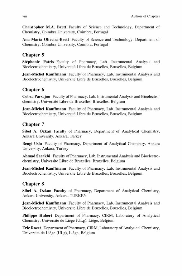
extent on the electrode’s useful potential range, in a particular solvent, Table 4.1,
and should always be chosen from the best quality and purity material. The
potential range within which the electrode can be used is called the working
potential window of the electrode, because only this potential range can be used
for analytical measurements. The limits are usually determined by solvent oxi-
dation and reduction, e.g. in water solvent to oxygen and hydrogen, respectively.
The increasing applications of solid electrodes are due to the fact that they have
good, or at least reasonable, negative and positive potential ranges compared with
the limited, almost non-existent, mercury electrode positive potential range [1–
19]. Solid electrode surface reproducibility is more difficult to control than the
renewable mercury electrode surface, but this is compensated by the advantage of
the solid electrode being more mechanically stable as well as their larger positive
potential range than mercury-based electrodes.
Table 4.1 Potential range of Hg, Pt and carbon electrodes
84 4 Solid Electrodes in Drug Analysis

Hydrogen ion reduction on mercury electrodes is very slow and occurs at
significantly more negative potentials than required by thermodynamics. This
phenomenon is called hydrogen overpotential and makes mercury a very useful
cathode. By contrast, mercury is easily oxidised at positive potentials.
Hydrogen ion reduction on Pt, Au, carbon, Bi and other solid electrode materials
occur at much less negative potentials but are much better in the positive potential
range (Table 4.1). In particular, working potential range of carbon electrodes is very
wide because of their high hydrogen overpotential and good stability under anodic
polarisation compared with most other solid electrode materials.
Research into the electron transfer oxidation reactions of many organic mole-
cules can only be undertaken using solid electrodes with an appropriate positive
potential range. In the selection of the solid electrode material, two factors have to
be taken into consideration: the redox behaviour of the investigated analyte and the
background current of the solid electrode over the potential region required for the
measurements.
At the surface of the solid working electrode, dissolved electroactive analytes
exchange one or more electrons. The solid electrode should have a reproducible
response and a high signal-to-noise ratio. The electroanalytical method will mea-
sure the current, which is proportional to the analyte concentration, on applying a
potential difference to the working electrode with respect to the reference electrode,
the latter having a constant potential.
The composition and the geometry of the solid electrode must be considered
since they will influence the performance and development of the electroanalytical
method.
4.3 Properties of Solid Electrode Materials
In the selection of the solid electrode material, the redox behaviour of the analyte,
the nature of the supporting electrolyte, the pH and the potential region required for
the measurement of the redox processes of electroactive drugs have to be
considered.
Solid electrodes can be made of different conducting materials and have differ-
ent geometries, sizes, hydrodynamic conditions under which they can operate and
active surface chemical modifications. Solid electrode surfaces are always much
more rough than a liquid mercury surface, but this also means that solid electrodes
can have a bigger electroactive surface area than the geometric area.
The performance of an electroanalytical method depends on the geometry and
material composition of the solid electrode. Thus, chemical inertness and electro-
chemical stability over a wide range of conditions, electrical conductivity, fast
electron transfer for a wide variety of redox systems, reproducible electrical and
chemical properties, must be taken into account when it is being developed. The
material should be easy to obtain and manufacture, non-toxic and inexpensive.
4.3 Properties of Solid Electrode Materials 85
Solid electrodes can be used in stationary, rotating and flow systems and have
different configurations such as planar, rod or tube.
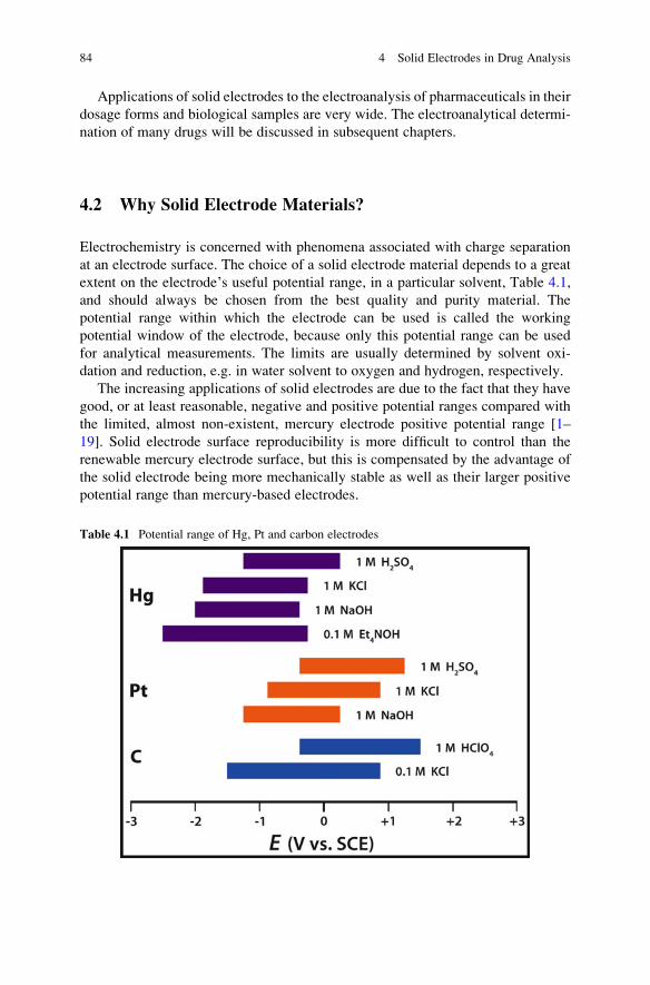
The most common solid electrode geometry consists of a disc of the solid
conducting electrode material, attached by conducting glue to a short cylindrical
conducting metal (such as brass) rod. This is inserted within a tightly fitting tube of
insulating material that is chemically inert in aqueous and non-aqueous electrolytes,
such as Teflon, PEEK, glass or epoxy resin, so that only the disc surface contacts
with the solution, the external electrical contact being made at the back, Fig. 4.1.
Such an inlaid disc is the most convenient form for cleaning and polishing.
However, precautions should be taken to avoid contamination of the solid surface
(e.g. with epoxy resin if this is used) during the preparation steps.
Diffusion of analyte to the solid electrode surface is influenced by the electrode
size (macro- or micro-) and geometry. Disc electrodes with diameters greater than
100 μm are called macroelectrodes, and the measured currents are in the μA to mA
range. Double working solid ring–disc electrodes have been used in rotating
systems, Fig. 4.2, and in flow systems such as wall-jet or thin-layer electrochemical
detectors.
Other solid electrode configurations include ultramicroelectrodes and micro-
fabricated screen-printed electrodes or silicon-based thin-film electrodes. Micro-
electrodes with dimensions less than 100 μm have currents in the pA to nA range.
Although the currents at microelectrodes are small and may require specialised
Fig. 4.1 Disc solid electrodes [Reprinted with permission from BAS Inc.]
86 4 Solid Electrodes in Drug Analysis

electrochemical equipment, they have a greater signal-to-background ratio owing to
enhanced diffusion and thence higher current density and, being small, find use in
applications where the small size is required.
The solid electrode surface can also be chemically modified in many ways
enabling a large number of applications in industry, quality control of drugs and
food, determination in pharmaceutical dosage forms, environmental
monitoring, etc.
4.4 Surface Cleaning Pre-treatments
The application of solid electrodes to drug analysis needs to take into consideration
the organic compound character of most medicinal drugs. Their redox processes are
usually accompanied by strong adsorption of the drug, its redox products or both, in
which case the solid electrode surface can be poisoned, leading to difficulties with
reproducibility. For this reason, and to ensure good reproducibility, surface
cleaning pre-treatment is usually required.
Electrode surface cleaning pre-treatments can be electrochemical and/or
mechanical that will always to have to be adjusted to the electroanalytical proce-
dure and drug analyte, and chemical pre-treatments with solid smooth electrode
surfaces can also be employed. Solid metal electrodes are usually polished mecha-
nically and are sometimes chemically etched with nitric acid or aqua regia. Suitable
Fig. 4.2 Photographs: (a) rotating disc electrode (RDE), (b) rotating ring–disc electrode (RDE).
(With permission from reference [20])
4.4 Surface Cleaning Pre-treatments 87
pre-treatment of the electrode surface should always precede any drug analysis
using a solid electrode.
Mechanical pre-treatment to a smooth mirror finish is achieved using abrasives,
such as diamond spray or alumina slurry, depending on the hardness of the
electrode material, on polishing tables or on cloths. Both diamond and alumina
abrasives are available in various particle sizes, and polishing should start using a
relatively large particle size and following with successively smaller sizes, usually
finishing with 1 micron particles. In some extreme cases, it may also be necessary to
use ultrasound after mechanical polishing with diamond or alumina to completely
remove all the abrasive particles from the pores of the electrode surface.
Electrochemical pre-treatment is usually achieved by cycling the electrode
potential between chosen limits in the supporting electrolyte until a steady state
baseline is obtained. The objective of this procedure is to activate and oxidise or
reduce the impurities or undesirable functionalities on the solid electrode surface.
In the case of metal electrodes, care should be taken that the electrochemical
pre-treatment only uses a cyclic voltammetry potential range between a positive
potential limit that is before the formation of the metal oxide layer and a negative
potential limit before hydrogen evolution.
A solid electrode surface conditioning cleaning procedure comprising mecha-
nical followed by electrochemical pre-treatment ensures very reproducible experi-
mental results.
4.5 Solid Electrode Materials
Many different solid materials are used for constructing working electrodes, such as
metals, different forms of carbon and surface-modified electrodes, and less com-
monly metal oxides and conducting polymers. The physical properties of the solid
electrode materials used in electroanalysis will now be reviewed.
4.5.1 Metal Electrodes
The most used solid metal electrode materials are Pt and Au. The first solid
electrode used in voltammetry was Ag [1–4, 21]. However, this electrode has an
extremely limited potential window and, therefore, restricted electroanalytical
applications. Other solid metal electrodes such as Bi, Pd, Rh, Cu, Ru, Ni, Cd, Sn
and In have also been used for specific electroanalytical applications. As an
example, Cu, Ni and Ag can be used for some specific applications on polar
aliphatic compounds such as carbohydrates and amino acid in different buffered
media.
Metals are very important solid electrode materials, with the advantage of high
conductivity and low background current. They are most often used for studying
88 4 Solid Electrodes in Drug Analysis
electron transfer kinetics, mechanism determination, thermodynamic parameters
and seldom in electroanalytical applications, although forced convection easily
increases their sensitivity and reproducibility. Metal electrodes usually have the
form of disc, ring or short wire electrodes.
In general, solid metal electrodes have low background currents, surfaces suit-
able for various sensing and detection applications and provide reproducible results.
Nevertheless, it should be kept in mind that their inertness is relative: at certain
applied potentials, oxides are formed by reaction between the electrooxidised metal
and oxygen, or hydrogen can adsorb on the metal surface. This can occur in aqueous
and in some non-aqueous solutions. An important factor in using solid electrodes is
the dependence of the response on the surface state of the electrode. Fundamental
studies of the electrolyte solution/metal electrode interface can only be made by
using well-defined single crystal electrodes.
Noble metals are commonly considered to be inert, but under certain electro-
chemical conditions electrochemical dissolution of the metal can occur; the metal
electrodes’ highly active surface can be covered by a surface oxide film over a
broad range of positive potentials. This will influence the electrode oxidation
processes since the electrochemical charge transfer reactions will occur at the
surface oxide rather than at the metal surface. Their limited use in electroanalytical
methods is also because of their rather low hydrogen overvoltage [1–4, 8–
12]. Using non-aqueous media, these difficulties and problems are less severe,
and noble metal electrodes are often an ideal choice.
For trace metal analysis, as an alternative to mercury film electrodes, Bi film
working electrodes are successfully used in stripping voltammetric methods and
they have been found to be more attractive and a good solid material to substitute
mercury film electrodes [1–5, 10–19]. Bi is an environmentally friendly element
and has low toxicity. Bi-modified electrodes are usually prepared in situ on a carbon
disc substrate, the most common being glassy carbon; they have a high hydrogen
overpotential, lead to wide linear dynamic ranges, low limits of detection and
excellent resolution of neighbouring peaks.
4.5.1.1 Platinum Electrodes
Of the noble metals, platinum is the most widely used electrode material. The main
advantage and widespread electrochemical use of Pt electrodes arises from its
relatively high chemical inertness, electrocatalytic properties, clear separation of
the potential regions for hydrogen and oxygen adsorption, excellent corrosion
resistance and ease of fabrication in many forms. For quantitative electroanalytical
studies, Pt electrodes of various geometries, Fig. 4.3, are mainly small discs, short
straight or helical wires and nets; disposable screen-printed Pt electrodes are also
available and will be described.
The biggest disadvantage in the use of Pt electrodes at positive potentials higher
than +0.8 V vs. SCE is formation of a Pt oxide layer, Fig. 4.4. The Pt oxide film can
strongly alter and slow down the kinetics of the electrode reaction or react with the
4.5 Solid Electrode Materials 89

analyte giving rise to unexpected behaviour, leading to irreproducible data [1–4, 12,
19]. Care must be taken to only use Pt at less positive potentials in order to keep the
electrode surface free from Pt oxide, Fig. 4.4 [22].
Another disadvantage of the use of Pt electrodes, besides its high cost, is that the
presence of even small amounts of water or acid in the electrolyte leads to the
reduction of hydrogen ion so that hydrogen evolution occurs at less negative
potentials, and at these potentials the Pt electrode is partially covered by a layer
of adsorbed hydrogen atoms, Fig. 4.4 [22].
The cyclic voltammogram for Pt in acid solution, Fig. 4.4, clearly shows the
anodic peaks corresponding to Pt oxide formation and the very broad cathodic peak
Fig. 4.3 Pt electrode different geometries [Reprinted with permission from BAS Inc.]
Fig. 4.4 Current–potential curve for platinum surface oxide formation and reduction in 0.5 M
H2SO4 (Reprinted with permission from [22])
90 4 Solid Electrodes in Drug Analysis
corresponding to subsequent Pt oxide reduction. At more negative potentials,
cathodic peaks occur corresponding to the reduction of the adsorbed hydrogen on
Pt followed on the reverse scan by the anodic peaks of adsorbed hydrogen on Pt.
Various pre-treatments can be used to clean the Pt electrode surface. Application
of very negative potentials should be avoided because, when scanning in the anodic
direction, anodic dissolution of adsorbed hydrogen can lead to incorrect results
being obtained.
4.5.1.2 Gold Electrodes
The second most widely used solid metal electrode is gold, usually less expensive
than platinum, but it is not as electrochemically inert. Similar to Pt, the Au electrode
in aqueous electrolyte at potentials higher than +0.8 V is covered by an Au oxide
film [1–4, 12, 19], making its use in the positive potential range reduced, Fig. 4.5.
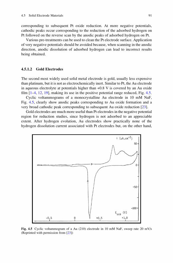
Cyclic voltammograms of a monocrystalline Au electrode in 10 mM NaF,
Fig. 4.5, clearly show anodic peaks corresponding to Au oxide formation and a
very broad cathodic peak corresponding to subsequent Au oxide reduction [23].
Gold electrodes are much more useful than Pt electrodes in the negative potential
region for reduction studies, since hydrogen is not adsorbed to an appreciable
extent. After hydrogen evolution, Au electrodes show practically none of the
hydrogen dissolution current associated with Pt electrodes but, on the other hand,
Fig. 4.5 Cyclic voltammogram of a Au (210) electrode in 10 mM NaF, sweep rate 20 mV/s
(Reprinted with permission from [23])
4.5 Solid Electrode Materials 91

the electrocatalytic activity for most charge transfer reactions is considerably lower
than at Pt electrodes.
In chloride-containing media, such as hydrochloric acid, Au electrodes should
not be used for anodic reaction studies due to the formation of a complex with
chloride, limiting the useful potential limit to ~ +0.6 V.
The other drawback of Au electrodes is adsorption blocking of the surface by
sulphur-containing species such as thiols, mercaptans and other inorganic sulphur
species such as hydrogen sulphide. The Au–S bond is very strong, but such
adsorption can be used to good effect to form self-assembled organosulphur mono-
layers. Au electrodes are also widely used as substrates for stripping analysis of
trace metals.
Similarly to Pt electrodes for quantitative electroanalytical studies, Au elec-
trodes of various geometries are used, mainly small discs or short wires. Various
cleaning pre-treatments can be used to clean the Au electrode surface depending on
the application [1–4, 12–19].
4.5.2 Carbon Electrodes
Carbon, in different forms, is the most widely used solid electrode material. All
carbon allotropes have been used, but the way the building blocks are put together is
different and the properties of the carbon allotropes themselves can vary widely.
The electronic properties, surface microstructure, surface chemistry, microstructure
and electronic properties are different, and this can influence redox system elec-
trode reaction kinetics and mechanisms.
The carbon allotropes most used are reticulated vitreous carbon (RVC), glassy
carbon (GC), graphite, highly oriented pyrolytic graphite (HOPG), carbon films,
carbon paste (CP), wax impregnated graphite (WIP), pencil lead graphite, boron-
doped diamond (BDD), carbon felt and cloth, carbon fibres, screen-printed carbon
(SPC), fullerenes, carbon nanotubes (CNT), graphene, Kel-graph, whiskers, tita-
nium carbide, etc. [1–4, 24–27]. All of these can be used for the electrochemical
analysis of organic electroactive drugs by reduction or oxidation, even at high
positive potentials by oxidation, and they are generally inexpensive.
Carbon fibres are the highest strength fibres, graphite one of the best lubricants,
diamond the strongest crystal and hardest material and glassy carbon is macroscopi-
cally non-crystalline but one of the best helium gas barriers, besides new forms of
carbon such as fullerene molecules and hexagonal polytypes of diamond.
Electrochemical reactions on carbon-based electrodes are normally slower than
at noble metal electrodes, the electron transfer kinetics being dependent on struc-
ture and surface preparation, and some background current, but they have a wider
potential range than metal electrodes in the negative and particularly so in the
positive direction, generally showing chemical inertness, and are of low cost.
The carbon atom has six electrons of which four, in its valence shell, fill the sp,
sp2 and sp3 hybrid orbitals which are responsible for the bonding structures in
92 4 Solid Electrodes in Drug Analysis
diamond, vitreous carbon, graphite, fullerene, pyrolytic carbon, nanotubes, etc.
This explains the ability of carbon to bond with itself and with other atoms in
very many combinations of chain and ring forms.
The study of the structure–function relationships at carbon-based electrodes has
to consider the surface chemistry, especially, the variety of surface oxygen func-
tional groups, particularly on sp2-bonded carbon materials, such as carboxy, car-
bonyl and hydroxyl, that occur on the oxidised carbon surface; the structure of
surface oxides on carbon is very complex. These influence reactivity, and thence
also chemical derivatisations that are possible on, for example, carbon paste, glassy
carbon, graphite and diamond surfaces. The high degree of delocalisation of πelectrons, together with weak van der Waals forces, provide good electrical con-
ductivity and influence the electrical double layer, molecular adsorption and elec-
trode polarity.
The graphitic sp2 atomic structure is present in different carbon materials such as
pyrolytic graphite, carbon nanotubes, graphene, vitreous carbon and carbon fibres.
Diamond, fullerene and allotropic lonsdaleite are sp3 atomic structure forms.
Within all used carbon electrode materials, graphite is by far the softest and
diamond is one of the hardest known materials [1–4, 15, 24–39].
The high surface activity of carbon materials explains their susceptibility to
poisoning by adsorption of organic compounds and especially by electroactive
pharmaceutical compounds.
Many pre-treatment cleaning procedures have been developed, depending on the
type of carbon, both renewing the surface and activating carbon-based electrodes,
and play a role in increasing the π electron transfer rates. Carbon electrode surfacesdo not interact with the accumulated or adsorbed compounds, a feature which rules
out the appearance of a systematic error caused by such interactions, but the
stability, surface area and reproducibility parameters in the analytical performance
largely depend on the surface after cleaning.
The successful application of carbon electrodes in electroanalytical studies of
electroactive pharmaceutical compounds is due to the high chemical and electro-
chemical stability of carbon materials, relatively high hydrogen and oxygen
overpotential in different electrolytes, a broad working potential range, simplicity
of mechanical renewal of the electrode surface and availability of different carbon
materials.
4.5.2.1 Graphite Electrodes
Graphite is one of the carbon allotropes and is produced with different sizes and
percentages of crystalline graphite, and consequently different conductivity and
stability. Graphite is a thermodynamically stable form of elemental carbon; it is one
of the softest minerals known to man and is a good conductor of electricity, Fig. 4.6
[1–4, 8–10, 15–19]. The electronically conductive carbons are derived from the
hexagonal crystalline modification of graphite. Graphite materials, such as
4.5 Solid Electrode Materials 93

pyrolytic graphite, carbon fibre, vitreous carbon, carbon black and others are
aggregates of graphite crystallites, referred to as polycrystalline graphite.
A single sheet of graphite is called graphene, consisting of carbon atoms packed
in a hexagonal lattice. Every carbon atom is bonded to three adjacent carbon atoms
that lie at the vertices of equilateral triangles by four valence electrons available to
participate in the formation of chemical bonds. Three of these electrons are used in
forming strong covalent bonds with the adjacent carbon atoms packed in a hexa-
gonal lattice in the sheet. This covalent bond has a short length and high strength
due to electrons shared between atoms. The fourth electron is free to wander over
the surface of the sheet making graphene an electrical conductor.
In graphite, the individual sheets of carbon atoms exist in parallel stacked layers,
in a layered structure, connected by van der Waals forces to form crystallites,
Fig. 4.6. The conductivity parallel to the carbon sheets is high and perpendicular
to them is low. Each sheet of carbon atoms is translated (offset) by one-half of a unit
such that alternate sheets are in the same position. The spacing between the layer
planes is relatively large (0.335 nm) or more than twice the spacing between atoms
within the basal plane (sheet) of 0.142 nm and approximately twice the van der
Waals radius of carbon. Because these forces are weak, the sheets can easily slide
past each other and graphite, unlike diamond, is therefore extremely soft, whereas
the graphene sheet has strong covalent bonding between the carbon atoms.
Graphite is remarkable for the large variety of materials that can be produced
from its basic form such as extremely strong fibres, easily sheared lubricants,
gas-tight barriers and gas adsorbers, and the sliding sheets give graphite its softness
for writing and its lubricating properties [1–4, 8–10, 15–19].
The choice of exposed basal or edge plane alters the electrochemical response
owing to the different structure of the exposed surface, see Fig. 4.6. The graphite
edge orientation is more reactive than is the graphite basal plane towards electron
transfer and adsorption. Different edge-to-basal plane ratios of carbon-based
Fig. 4.6 Structure of graphite
94 4 Solid Electrodes in Drug Analysis
materials display different observed electron transfer kinetics for the investigation
of a redox active compound.
Large single crystals of graphite are rare; therefore, graphite is employed in
polycrystalline form (solid blocks, paste electrodes, suspensions, etc.). Neverthe-
less, some carbons prepared by chemical vapour deposition (pyrolytic carbons)
match the properties of a graphite single crystal [1–4, 8–10, 15–19].
Pores arising in graphite are sometimes impregnated with ceresin or paraffin
under vacuum in order to impede the entry of solution into the graphite electrode
lattice. When the in-plane dimension of the graphene sheet is small (i.e. high
fraction of crystallite edges) and the spacing between them is large, this carbon is
designated as amorphous (e.g. powders and glassy carbon). These materials are
isotropic, as they have the same conducting properties in all directions.
The definition of the difference between “graphite” and “carbon” is somewhat
subjective. It is normally considered that carbon has a non-ordered atomic structure,
i.e. “amorphous”, although most carbons have small crystallites of graphitic struc-
ture, and are isotropic, since they have the same conducting properties in all
directions.
Spectroscopic graphite with a low level of metallic impurities is used in graphite
rod electrodes for electroanalytical applications. Graphite composite electrodes are
prepared from graphite powder mixed with a suitable binder and then bonded,
either physically or chemically, to form a conductive solid composite.
Pyrolytic graphite is very pure and exhibits anisotropic properties, depending on
the crystal orientation. The supported layer of pyrolytic graphite is actually poly-
crystalline, but the individual crystallites show a higher degree of preferred orient-
ation with carbon hexagons parallel to the surface of the substrate. Such graphite
can be either natural or artificial/synthetic.
The artificial type is called highly ordered pyrolytic graphite (HOPG), Fig. 4.7a,
and is prepared by exposing pyrolytic graphite to high pressure and high temper-
ature. It is a relatively new form of highly pure graphitic carbon and is an excellent
atomically flat substrate with a renewable and smooth surface, especially for use in
atomic force microscopy (AFM), Fig. 4.8.
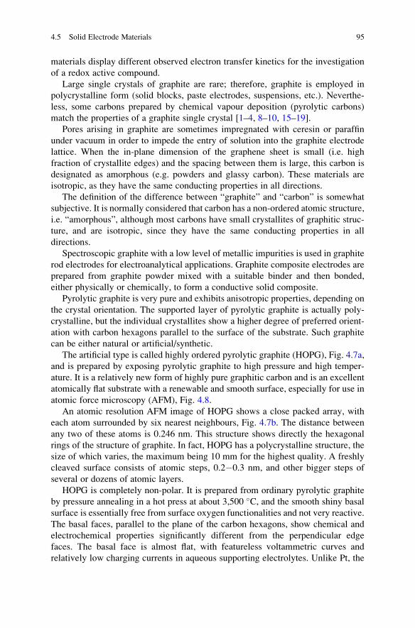
An atomic resolution AFM image of HOPG shows a close packed array, with
each atom surrounded by six nearest neighbours, Fig. 4.7b. The distance between
any two of these atoms is 0.246 nm. This structure shows directly the hexagonal
rings of the structure of graphite. In fact, HOPG has a polycrystalline structure, the
size of which varies, the maximum being 10 mm for the highest quality. A freshly
cleaved surface consists of atomic steps, 0.2�0.3 nm, and other bigger steps of
several or dozens of atomic layers.
HOPG is completely non-polar. It is prepared from ordinary pyrolytic graphite
by pressure annealing in a hot press at about 3,500 �C, and the smooth shiny basal
surface is essentially free from surface oxygen functionalities and not very reactive.
The basal faces, parallel to the plane of the carbon hexagons, show chemical and
electrochemical properties significantly different from the perpendicular edge
faces. The basal face is almost flat, with featureless voltammetric curves and
relatively low charging currents in aqueous supporting electrolytes. Unlike Pt, the
4.5 Solid Electrode Materials 95

HOPG basal plane does not adsorb anions and most organic substances can be
cleaved with adhesive tape, the new exposed clean surface remaining stable in air
for many hours.
Due to their anisotropic structure, pyrolytic graphite and HOPG electrodes have
differences in their preparation procedures. Both pyrolytic graphite and highly
ordered pyrolytic graphite have weak interplanar bonds, and may be manually
cleaved to expose basal surfaces. Teflon or epoxy resin are usually used to make
the electrode holder material, a cylindrical recess drilled into a Teflon rod, and an
electrical contact placed in the back of the recess, as for metal electrodes.
Some conventional cleaning pre-treatment procedures, such as mechanical
polishing, cannot be employed because of the softness of HOPG and pyrolytic
graphite. So, chemical cleaning in a convenient solvent, laser activation, heat
treatment and electrochemical pre-treatment procedures have to be applied. For
solvent cleaning, solvents such as acetonitrile, toluene and dichloromethane can be
Fig. 4.7 Structure of highly oriented pyrolytic graphite (a) [Reprinted with permission from [40],
(b) AFM (Reprinted with permission from [41])
Fig. 4.8 Structure of glassy carbon. (Reprinted with permission from [46])
96 4 Solid Electrodes in Drug Analysis
used. This pre-treatment works by dissolving materials adsorbed on the surface [3,
4, 10, 15, 39, 42–44]. Laser activation pre-treatment can be used to activate HOPG
towards electron transfer. This pre-treatment cleans existing active sites and can
create new ones, depending on the experimental conditions. The heat treatment
procedure activates HOPG by desorbing contaminants or removing chemisorbed
oxygen from the exposed edge plane sites, depending on the temperature. Electro-
chemical pre-treatment is the most used cleaning procedure.
Although, graphite-based electrodes are not as widely used as glassy carbon,
boron-doped diamond, carbon paste or carbon nanotube electrodes [15–19, 39, 42–
44]; they have also been used for the electroanalytical determination of drugs in
their dosage forms and in biological samples.
4.5.2.2 Glassy Carbon Electrodes
Glassy carbon (GC), also referred to as vitreous carbon, a material which started
being manufactured in the early 1960s, is a conductive form of carbon usually made
by pyrolyzing precursors and is the most commonly used carbon electrode in
electroanalysis since the 1980s [2–4, 15, 18, 19].
The structure of GC consists of graphitic planes randomly organised as tetra-
hedral domains in a complex topology linked by short oxygen-containing bridges,
closely related to that of a vitreous material, with high lustre and glass-like fracture
characteristics, hence the designations of glassy carbon, vitreous carbon or pyro-
lytic carbon. Unlike HOPG and other graphites, GC is microstructurally isotropic,
the same electrical properties in all directions, and very hard, like diamond, thus
making it moderately expensive compared with Pt and Au electrodes. It is difficult
to machine in different electrode geometries, the most available being rods, discs
and plates, and with a wide potential range, due to the high overpotentials for
hydrogen and oxygen evolution.
The GC material is prepared from a pre-modelled polymeric
(e.g. polyfurfurylalcohol or phenolic) resin body in an inert atmosphere by carefully
applying a controlled heating programme (at temperatures between 1,000 and
3,000 �C) under pressure, and an increased electrical conductivity is obtained on
increasing the preparation temperature [2–4, 15, 18, 19, 45]. The heat treatment is
often applied slowly over days and causes release of atoms other than carbon,
producing a conjugated graphitic microstructure. The original polymer backbone
stays largely intact, preventing the formation of extended graphitic domains. The
GC microstructure, Fig. 4.9, is a material of pure carbon combining glass-like high
mechanical hardness characteristics due to the interwoven sp2 carbon ribbons,
(characterised by randomly oriented strips (lamellae) of pseudographitic layers of
carbon hexagons) with the physical properties of graphite. The accepted model for
the GC microstructure, Fig. 4.9, is that proposed by Jenkins and Kawamura [2–4,
15, 18, 19].
The random structure of GC, Fig. 4.9 [46], bears some resemblance to that of a
polymer, in which the fibrils are very narrow curved and twisted ribbons of
4.5 Solid Electrode Materials 97
graphitic carbon [2–4, 31, 35, 38, 47, 48]. These ribbon-like tangled aromatic
molecules are cross-linked by carbon–carbon covalent bonds with varying bond
energies. Some of these bonds may be highly strained. This extremely high density
and small fine-pore size structure gives GC characteristics that enable the adsorp-
tion of some small molecules such as water, methanol and isopropanol.
In contrast to graphite, GC has isotropic electrical conductivity and has remark-
able physico-chemical properties, such as high strength and high resistance to
chemical attack. It is mechanically polishable and is extremely impermeable to
gases and liquids.
GC can be produced in three basic types which have essentially the same
microstructure, but different macrostructures: solid monolithic vitreous, foam reti-
culated, spheres or particles, the most common being vitreous carbon, Fig. 4.9, and
reticulated carbon. The density of GC is less than HOPG, indicating that it is a
nanoporous material and contains some void spaces, Fig. 4.8.
GC is extremely resistant to many chemicals especially when prepared at very
high temperatures. Only strong oxidising agents like oxygen at elevated temper-
ature, or hot melts, or strong oxidising acids can attack glassy carbon. But even
under these circumstances, it is probably the most inert carbon-based material [2–4,
15, 31, 47, 48]. According to the general specifications, GC is similar to poly-
crystalline graphite in composition, bonding and resistance, but differs greatly in
porosity, low density, high hardness, high strength, good electrical conductivity and
mechanical properties, all due to the difference in structure.
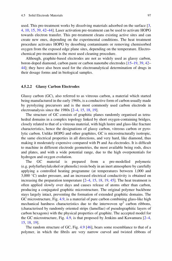
Electrochemical experiments normally give rise to similar redox behaviour at
GC and HOPG electrodes. However, the HOPG surface is used as a substrate in
AFM studies, because it is atomically flat with less than 0.06 nm of root-mean-
square (r.m.s.) roughness for a 1,000� 1,000 nm2 surface area, Fig. 4.9A, whereas
the GC electrode is only used for voltammetric characterisation as it is much
rougher, with 2.10 nm r.m.s. roughness for the same surface area, Fig. 4.9B,
therefore unsuitable for AFM surface characterisation.
Fig. 4.9 AFM topographical images in air: (A) HOPG and (B) GC electrodes. (Reprinted with
permission from [41])
98 4 Solid Electrodes in Drug Analysis

Reticulated vitreous carbon (RVC), also called polymeric carbon since it derives
mostly from the carbonisation of polymeric precursors, is an open-pore foam
material of honeycomb structure composed solely of vitreous carbon, one of the
most chemically inert forms of carbon known which is resistant to oxidation,
Fig. 4.10.
RVC has an exceptionally high void volume (90�97 %), high porosity, high
surface area, rigid structure, low density and low resistance to fluid flow, very good
mechanical properties, high corrosion resistance and lower thermal conductivity
than other forms of carbon but has a very high resistance to temperature change in
non-oxidising structures [1–4, 15, 31, 50].
However, the skeletal structure of RVC is fragile and brittle and needs physical
support, and the low volumetric carbon content per area means that care has to be
taken to ensure a uniform potential and current distribution through the material.
The RVC electrode surface can easily become poisoned when used for organic drug
oxidation studies, and it is difficult to avoid the drugs and oxidation products being
accumulated in the pores, even using chemical solvents. This limits the use of
RVC for the reproducible electroanalytical determination and screening of pharma-
ceutical dosage forms and biological fluids.
4.5.2.3 Carbon Paste and Carbon Composite Electrodes
Carbon paste electrodes (CPE) were introduced in 1958 by R.N. Adams for the
electroanalytical determinations of drugs [34]. They are prepared using a dispersion
of carbon particles mixed in a pasting liquid, with good positive and negative
potential range, and have since attained very broad applications in electroanalysis
[18, 19, 30–38]. The electroactive surface area is very similar to that of a single-
phase electrode of the same size. The reason is that the surface is composed of tiny
Fig. 4.10 Reticulated
vitreous carbon structure.
(Reprinted with permission
from [49])
4.5 Solid Electrode Materials 99

micron-sized carbon particles, which acts as a microelectrode assembly with
overlapping diffusion fields.
CPEs are a type of carbon composite electrodes, which all use electrically
conductive carbon particle powder mixed with an insulating binder. In the case of
CPEs, examples of pasting liquids are water-immiscible non-conducting organic
binders such as Nujol, uvasol, paraffin oil, silicon oil, bromonaphthalene and
bromoform. CPEs offer an easily renewable and modified surface, are of low cost
and normally have a very low background current over the entire positive and
negative potential range [18, 19, 30–38]. Classical graphite particles are now often
replaced by particles of other forms of carbon such as fullerenes, carbon nanotubes,
graphene and carbon fibres. Pasting liquids are being replaced by binders which
become solid such as polyurethane, Kel-F and Kelgraph, in this case forming a
conductive solid composite electrode, the surface of which can be polished in the
same way as other solid electrodes.
The basic requirements for an organic binder are its insolubility in the solution
under measurement, a low vapour pressure to ensure both mechanical stability and
long lifetime and inertness in the working potential range in electroanalytical studies
[18, 19, 51–55]. It is also important to use an organic binder that does not cause the
electron transfer rates to decrease on increasing the amount of pasting liquid.
Graphite can also be impregnated with resins, in order to produce tight materials
of high chemical stability. This type of polycrystalline graphite electrode is called
wax-impregnated graphite electrode (WIGE). The modifier is either dissolved in
pasting liquid or physically mixed with the paste when preparing a modified carbon
paste electrode. The modifier itself could be electroactive or may be a complexing
agent which can extract an electroactive analyte into the surface layers of the paste
electrode. After evaporating the solvent, the impregnated carbon powder is ready to
use [2–4, 18, 19, 55–62].
The nature and behaviour of common carbon pastes can be described by means
of physico-chemical properties such as composite character, hydrophobicity, con-
ductivity, disintegration and lifetime. Some surface treatments can also improve
polarisation characteristics of carbon pastes. The potential range of commonly used
carbon pastes also depends on the pH of the working electrolyte solutions in a way
that can differ from bulk carbon to some extent, but this is usually minor.
Fullerenes are a new class of carbon-only molecules, discovered in 1985 by
Kroto [63], the most well-known being composed of 60 carbon atoms (C60)
arranged in a soccer ball structure, Fig. 4.11. They are carbon clusters, whose
surface is formed by 12 pentagons and any number of hexagons. As can be deduced
from Fig. 4.11, fullerene is based on sp2 hybridised carbon like glassy carbon and
graphite, but differs in its topology. Despite the presence of fused hexagons of sp2
carbons, fullerenes do not create planar sheets as graphite does. Their large surface
area, stability and wide positive potential range have prompted their use in CPEs
after mixture with appropriate pastes.
Carbon paste is typically ready within a few minutes and can also be stored in a
suitable container for later use or packed immediately into the electrode body, but
long-time storage is not recommended because of their limited lifetime. It is
recommended to prepare only the necessary amount of paste and use it immediately.
100 4 Solid Electrodes in Drug Analysis

Disc CPEs are prepared by inserting the carbon paste in a shallow hole drilled
into a short Teflon rod, polyethylene syringe or glass tube [1, 55], which is in
electrical contact with a wire at the back, Fig. 4.12. The surface is best smoothed by
Fig. 4.11 Buckminsterfullerene, C60 [63] (Reprinted with permission from [64])
Fig. 4.12 Preparation of carbon paste disc electrodes [Reprinted with permission from BAS Inc.]
4.5 Solid Electrode Materials 101

rubbing the electrode several times and slowly polishing on a mildly abrasive
surface.
CPEs are one of the most simple and easy to prepare carbon-based electrodes,
with precision in current measurements, only surpassed by noble metal electrodes,
and with a large surface area, important to use for drug electroanalysis.
Surface renewal can be done by replacing an outer layer of the paste and
re-smoothing it, providing a fresh surface unaffected by the electrode history. In
some assemblies, the internal metal rod is attached to a screw thread so that the
paste can be extruded and then smoothed. If a plastic sheath is used then renewal
can be done by cutting. A further alternative is to use it in disposable electrode
form. This demonstrates that each carbon paste electrode surface is an individual
surface, and there may be some differences between surfaces, affecting
reproducibility.
4.5.2.4 Carbon Fibre Microelectrodes
Carbon fibres are a type of high strength material, often stronger than steel but much
lighter, with very wide applications and have been available for more than 40 years.
Like all forms of conductive carbon are produced by high-temperature pyrolysis, at
several hundred or thousand degrees Celsius, of a carbon-based precursor, such as a
polymer textile, or via catalytic chemical vapour deposition [1–4, 13–19, 64–
68]. The heat treatment process is similar to that for the preparation of glassy
carbon. Typical dimensions of the carbon fibre tip are in the range of 5–20 μmdiameter and 5–15 mm length.
Highly oriented polyacrylonitrile (PAN)-based fibres have an “onion” type
arrangement of the “concentric” or “random” graphite layers, whereas pitch-
based fibres have a cross section of “radial” or ”PanAm” graphitic lamellae,
Fig. 4.13 [69].
Carbon fibre electrodes have at least one dimension that is micron size, the disc
end, so they are microelectrodes, with a radial diffusion of the solution analyte to
the carbon fibre microelectrode surface.
They are very strong in the axis direction, have small ohmic drops and low
background current [67, 68], due to their well-ordered graphite-like structure and
low porosity. Carbon fibres are normally cut to a length of ~0.5 mm prior to use and
typically mounted at the tip of a pulled glass capillary with epoxy adhesive,
Fig. 4.14 [70].
Microelectrodes offer some advantages over conventional solid and micro-
electrodes in electrochemical studies in terms of a faster response time; a lower
background current and a smaller size that enables measurements to small amount
of samples; etc.
A major advantage of the carbon fibre microelectrodes is the possibility of using
high scan rates. Because of their small electrode area, reduced capacitance and fast
time constants can be obtained and thence discrimination against charging currents
102 4 Solid Electrodes in Drug Analysis

[66–68], and scan rates exceeding 1 V/s can be used. This makes them ideal for use
in fast-scan cyclic voltammetry.
Carbon fibres have been used in anodic measurements in various micro-
environments, such as neuroelectrochemistry research in brain slices or in vivo in
rat brains, in single cells or in vesicular volumes. They have the ability to monitor in
a subsecond time frame and record in real time and, additionally, other devices
cannot be used because they are too big.
Fig. 4.13 Typical schematic cross sections of highly oriented carbon fibres. (Reprinted with
permission from [69])
Fig. 4.14 (a) A scheme of a fine carbon-fibre microelectrode. (1) Micropipette; (2) carbon-fibre;
(3) thick-walled capillary; (4) copper leading-out wire; (5) Wood’s alloy. (b) Microphotograph of
a part of the carbon-fibre situated within the micropipette’s tip. In process of introducing the fibre
into the micropipette, this part of the fibre bends slightly under the applied pressure. (1) Glass;
(2) carbon fibre. (Reprinted with permission from [70])
4.5 Solid Electrode Materials 103
4.5.2.5 Carbon Nanotube Electrodes
Nanotubules of graphite were observed in 1991 by Iijima deposited on the cathode
during the direct current arcing of graphite for the preparation of fullerenes [71],
and since then different methods were developed for carbon nanotube (CNT)
preparation, such as chemical deposition from the gas phase, arc discharge between
graphite electrodes or laser evaporation, etc. [72–77].
CNTs are the only form of carbon with extended bonding and yet with no
dangling bonds and represent an increasingly important group of nanomaterials
with unique geometric, mechanical, electronic and chemical properties. They are
one of the most important classes of “new” carbon materials consisting of hollow
cylinders made of carbon.
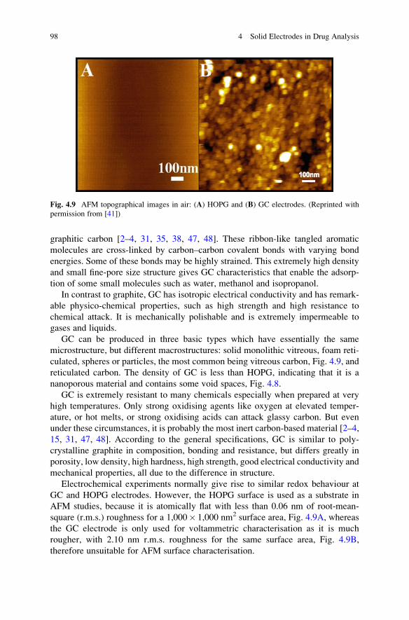
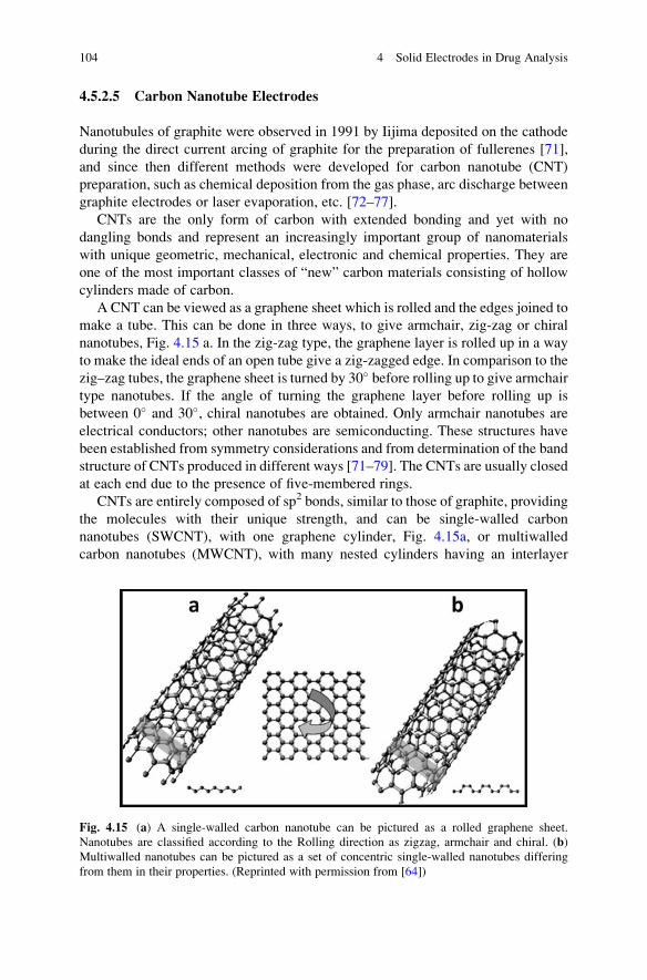
A CNT can be viewed as a graphene sheet which is rolled and the edges joined to
make a tube. This can be done in three ways, to give armchair, zig-zag or chiral
nanotubes, Fig. 4.15 a. In the zig-zag type, the graphene layer is rolled up in a way
to make the ideal ends of an open tube give a zig-zagged edge. In comparison to the
zig–zag tubes, the graphene sheet is turned by 30� before rolling up to give armchair
type nanotubes. If the angle of turning the graphene layer before rolling up is
between 0� and 30�, chiral nanotubes are obtained. Only armchair nanotubes are
electrical conductors; other nanotubes are semiconducting. These structures have
been established from symmetry considerations and from determination of the band
structure of CNTs produced in different ways [71–79]. The CNTs are usually closed
at each end due to the presence of five-membered rings.
CNTs are entirely composed of sp2 bonds, similar to those of graphite, providing
the molecules with their unique strength, and can be single-walled carbon
nanotubes (SWCNT), with one graphene cylinder, Fig. 4.15a, or multiwalled
carbon nanotubes (MWCNT), with many nested cylinders having an interlayer
Fig. 4.15 (a) A single-walled carbon nanotube can be pictured as a rolled graphene sheet.
Nanotubes are classified according to the Rolling direction as zigzag, armchair and chiral. (b)
Multiwalled nanotubes can be pictured as a set of concentric single-walled nanotubes differing
from them in their properties. (Reprinted with permission from [64])
104 4 Solid Electrodes in Drug Analysis
spacing approximately that of graphite, Fig. 4.15b. This bonding structure, which is
stronger than the sp3 bonds found in diamond, provides CNT with their unique
strength but using hexagons alone, carbon cannot yield closed three-dimensional
structures.
Thus, SWCNT have diameters in the range of 2–3 nm whereas MWCNTs are
made of concentric tubes, with external diameters that can vary up to 100 nm [76–
79]. Their unique structure results in unique macroscopic properties, including high
tensile strength, high electrical conductivity, high resistance to heat and lack of
chemical reactivity in many circumstances. The inner layer tubes of the MWCNT
have π-orbitals in their structure similar to graphite, and the interactions between
neighbouring tubes within the MWCNT lead to additional stabilisation compared to
SWCNT.
CNTs with different diameters can be prepared by various methods, including
electrochemical synthesis and pyrolysis of precursor organic molecules, and some
of these tubes may fit one into another to make a MWCNT. Electron micrographs
show that the space between individual tubes is usually ~0.34 nm, Fig. 4.15.
In order to make CNT-modified electrodes, it is often necessary to functionalise
them first, in order to introduce surface functional groups and increase the hydro-
philic character. The functionalised CNTs are deposited onto a conducting surface
like glassy carbon or graphite, where they will be immobilised in both oriented and
non-oriented positions, increasing the electroactive surface area of the substrate
electrode. Sometimes Nafion or a conducting polymer is added to improve the
physical robustness of the modifier layer.
Covalent functionalisation of the CNTs structure is achieved after purification of
the nanotubes obtained from different production methods. Reaction with hot,
concentrated oxidising mineral acids like nitric or sulphuric acids introduces
carboxyl groups at the ends of the tubes and defects on the side walls. For
MWCNT, the reaction has to be carefully controlled and the conditions adjusted
to determine whether or not the outer walls of the tubes are oxidatively removed,
allowing a variation not only of the length, but even of external tube diameter.
Carboxyl derivatives obtained from the oxidative opening of nanotubes can be
further modified by classical organic chemistry methods. The attachment products
from long alkyl chains exhibit a markedly increased solubility in organic solvents.
The debundling of SWCNT can also be promoted by the opening and
functionalising the end of tubes as the intertubular van der Waals exchange
decreases due to the modification.
CNTs are one of the most commonly used building blocks in nanotechnology.
Their attractiveness as electrochemical nanoprobes is due to their small size, with
larger surface area, high sensitivity, fast and reproducible responses, good conduc-
tivity and high chemical stability. The signal is increased compared with other
traditional carbon-based electrodes, such as carbon paste or glassy carbon, due to
the CNT high surface area [75–90]. Additionally, there may be electrocatalytic
effects compared to other forms of carbon, owing to active sites associated with
CNT defects. Additional defects can be introduced by nitrogen doping during CNT
synthesis, nitrogen atoms substituting carbon atoms, which can lead to enhanced
4.5 Solid Electrode Materials 105

electrocatalytic effects [81]. The chemical and electrochemical properties of carbon
nanotubes can be particularly considered as suitable for the design of a variety of
sensors, and CNTs have been used to build novel electrodes with interest for
electroanalytical applications.
4.5.2.6 Boron-Doped Diamond Electrodes
Diamond and graphite are two of the most interesting minerals and are both carbon
allotropes. Diamonds are transparent and brilliant, whereas graphite is opaque and
metallic. Another important physical difference is their hardness. Diamond is the
hardest known substance in nature, is used to cut glass and in industrial drill bits, is
widely sought after because of its rarity and unique crystalline structure and is used
in jewellery. Graphite is very soft. The reason for their extreme differences in
hardness and other physical properties is explained by their molecular crystal
structure.
Diamond is typically crystallised in the “cubic” system, consisting of sp3
hybridised tetrahedrally bonded carbon atoms, Fig. 4.16. Micro-structurally, the
atoms arrange themselves in stacked, six-membered rings in a puckered rather than
a planar conformation. Diamond has an extraordinary chemical stability, is in-
soluble in water and organic solvents, has a very high melting point (about
4,000 �C) and is therefore a very poor electrical conductor with no surface redox
processes as that occur for other carbon electrodes.
Boron-doped diamond (BDD), Fig. 4.17, has been developed as a new conduc-
tive material in which an industrial diamond film is doped with boron, becoming
electrically conducting. BDD electrodes have found many applications as electrode
material in electroanalysis.
BDD thin films can be produced synthetically by one of several established
deposition protocols, the most popular being hot filament and microwave-assisted
chemical vapour deposition, using boron-containing compounds such as
trimethylboron, trimethyl borate or B2H6. [92–96]. Boron is easily incorporated
in the diamond film, substituting carbon atoms in the lattice. Heavily doped films
are produced in this way making synthesised diamond semi-conducting, but also
affecting factors such as growth rate, morphology and crystallinity, as well as
conductivity of the diamond particles, Fig. 4.17e [97].
Fig. 4.16 Diamond
structure
106 4 Solid Electrodes in Drug Analysis
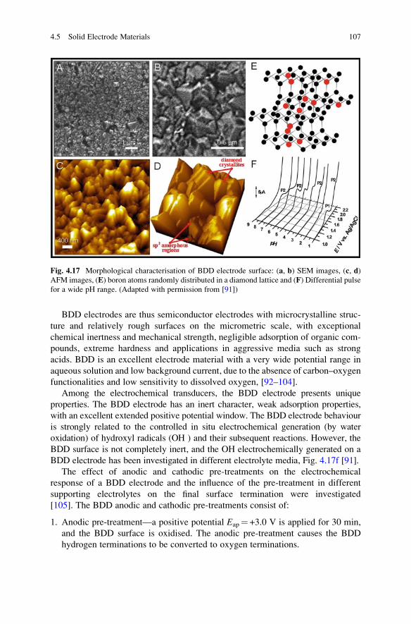
BDD electrodes are thus semiconductor electrodes with microcrystalline struc-
ture and relatively rough surfaces on the micrometric scale, with exceptional
chemical inertness and mechanical strength, negligible adsorption of organic com-
pounds, extreme hardness and applications in aggressive media such as strong
acids. BDD is an excellent electrode material with a very wide potential range in
aqueous solution and low background current, due to the absence of carbon–oxygen
functionalities and low sensitivity to dissolved oxygen, [92–104].
Among the electrochemical transducers, the BDD electrode presents unique
properties. The BDD electrode has an inert character, weak adsorption properties,
with an excellent extended positive potential window. The BDD electrode behaviour
is strongly related to the controlled in situ electrochemical generation (by water
oxidation) of hydroxyl radicals (OH ) and their subsequent reactions. However, the
BDD surface is not completely inert, and the OH electrochemically generated on a
BDD electrode has been investigated in different electrolyte media, Fig. 4.17f [91].
The effect of anodic and cathodic pre-treatments on the electrochemical
response of a BDD electrode and the influence of the pre-treatment in different
supporting electrolytes on the final surface termination were investigated
[105]. The BDD anodic and cathodic pre-treatments consist of:
1. Anodic pre-treatment—a positive potential Eap¼ +3.0 V is applied for 30 min,
and the BDD surface is oxidised. The anodic pre-treatment causes the BDD
hydrogen terminations to be converted to oxygen terminations.
Fig. 4.17 Morphological characterisation of BDD electrode surface: (a, b) SEM images, (c, d)
AFM images, (E) boron atoms randomly distributed in a diamond lattice and (F) Differential pulse
for a wide pH range. (Adapted with permission from [91])
4.5 Solid Electrode Materials 107
2. Cathodic pre-treatment—a negative potential Eap¼�3.0 V applied for 30 min,
and the BDD surface is reduced. The cathodic pre-treatment causes an increase
in the thickness of the adsorption layer formed by hydrogen termination.
The electrochemical response of the BDD surface varies as a function of surface
pre-treatment and also with the electrolyte used in the pre-treatment, significant
oxygen evolution always occurring at +1.4�1.6 V.
Despite the many advantages of BDD electrodes, their high cost and difficulties
in finding an appropriate substrate on which to deposit the thin diamond layer are
major drawbacks to widespread application.
Nevertheless, the applications of BDD electrodes have demonstrated their supe-
rior electrochemical properties that are significantly different from those of other
carbon electrodes, e.g. GC and HOPG. The very low background current is less than
that at metal and GC electrodes, making the BDD electrode superior to other
electrode materials, enhancing the sensitivity for the detection of a number of
pharmaceutically and biologically important compounds that exist at nanomolar
or picomolar concentrations.
The BDD electrode surface is mechanically inert against polishing or cavitation
during exposure to ultrasound radiation; it is chemically inert against aggressive
chemicals and under extreme polarisation.
4.5.3 Screen-Printed Electrodes
Screen-printing technology is widely used for the mass production of disposable
electrochemical sensors, Fig. 4.18. Since the 1990s, screen-printing technology,
adapted from the microelectronics industry, has offered high-volume production of
extremely low cost and yet highly reproducible and reliable single-use disposable
SPE sensors; a technique which holds great promise for on-site monitoring.
The complete electrochemical electrode set configuration, i.e. working, refer-
ence and auxiliary electrode, is contained in a disposable screen-printed electrode
(SPE) that is highly suitable for working with micro-volumes and decentralised
assays or to develop specific sensors by modifying their surface with various
materials, usually in a strip form, Fig. 4.18. SPEs have been used successfully in
the development of sensors and biosensors in various configurations for a wide
range of analytical applications [107–111].
SPEs can be made of carbon, Au, Pt, Bi, AGr or CNT inks. The support is coated
on defined areas with a conducting ink that contains the electrode active material.
Part is then covered by an insulating film to define an external electrical contact at
one extremity and an electrode surface at the other, Fig. 4.18. Typical dimensions of
the SPE strip are H33�L10�W0.5 mm. The shape and the surface of SPEs are not
nearly as smooth as more traditional electrodes such as metal, pyrolytic graphite or
GC electrodes [107–119].
108 4 Solid Electrodes in Drug Analysis
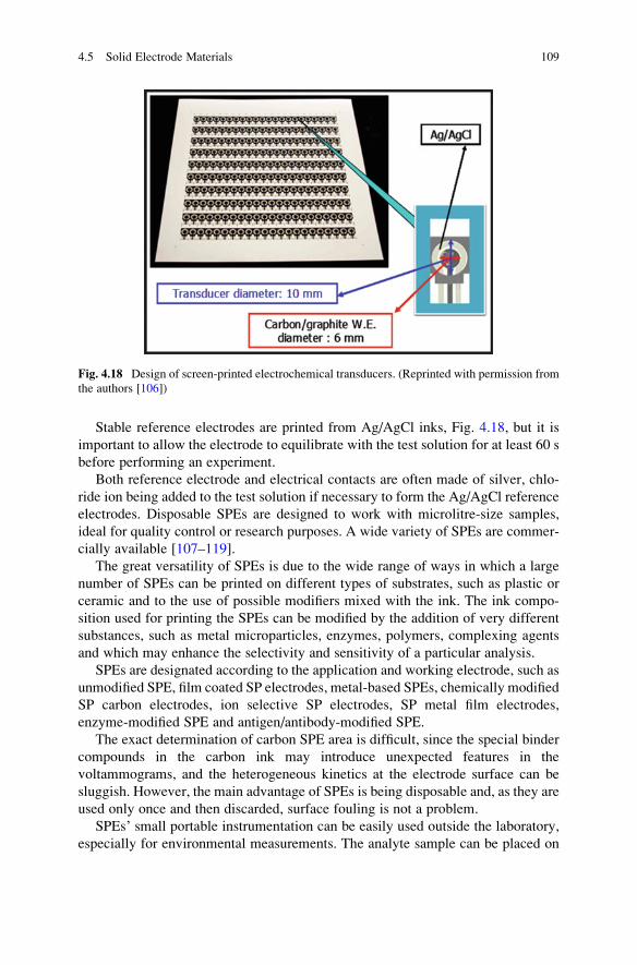
Stable reference electrodes are printed from Ag/AgCl inks, Fig. 4.18, but it is
important to allow the electrode to equilibrate with the test solution for at least 60 s
before performing an experiment.
Both reference electrode and electrical contacts are often made of silver, chlo-
ride ion being added to the test solution if necessary to form the Ag/AgCl reference
electrodes. Disposable SPEs are designed to work with microlitre-size samples,
ideal for quality control or research purposes. A wide variety of SPEs are commer-
cially available [107–119].
The great versatility of SPEs is due to the wide range of ways in which a large
number of SPEs can be printed on different types of substrates, such as plastic or
ceramic and to the use of possible modifiers mixed with the ink. The ink compo-
sition used for printing the SPEs can be modified by the addition of very different
substances, such as metal microparticles, enzymes, polymers, complexing agents
and which may enhance the selectivity and sensitivity of a particular analysis.
SPEs are designated according to the application and working electrode, such as
unmodified SPE, film coated SP electrodes, metal-based SPEs, chemically modified
SP carbon electrodes, ion selective SP electrodes, SP metal film electrodes,
enzyme-modified SPE and antigen/antibody-modified SPE.
The exact determination of carbon SPE area is difficult, since the special binder
compounds in the carbon ink may introduce unexpected features in the
voltammograms, and the heterogeneous kinetics at the electrode surface can be
sluggish. However, the main advantage of SPEs is being disposable and, as they are
used only once and then discarded, surface fouling is not a problem.
SPEs’ small portable instrumentation can be easily used outside the laboratory,
especially for environmental measurements. The analyte sample can be placed on
Fig. 4.18 Design of screen-printed electrochemical transducers. (Reprinted with permission from
the authors [106])
4.5 Solid Electrode Materials 109
the exposed electrodes in the form of small drop in situ. In the laboratory, they can
be used in a larger volume of analyte-containing solution, appropriate for analysis
of pharmaceutical or biological samples.
4.5.4 Chemically Modified Electrodes
Chemically modified electrodes (CMEs) consist of conducting or semiconducting
materials modified using different reagents with the objective of obtaining specific
surface properties for electroanalytical applications. Such manipulation of the
molecular composition of the electrode surface aims at improving sensitivity,
selectivity and/or stability, tailoring the response in order to meet new analytical
needs [120–132].
The enhanced selectivity of CMEs can be obtained by either an analyte-specific
pre-concentration effect or by selecting a layer with properties that catalyse a
specific reaction [115, 121, 133–139]. Whilst conventional voltammetric and
amperometric electrodes serve mainly for carrying the electrical current, powerful
sensing devices can be designed relying on specific modification of their surfaces.
The unmodified electrodes are called “bare”, “native” or “virgin” electrodes [33,
59].
CMEs are made by physisorption/chemisorption, covalent bonding, sol–gel
encapsulation, coating the surface by a polymer, by polynuclear or mixed films or
by mixing the modifier with the electrode matrix material, i.e. composite modifi-
cation. Good control of electrode characteristics and reactivity is achieved by the
surface modification [1–4, 115, 121–143].
The main objectives of chemical modification are:
– Acceleration of electron transfer reactions
– Enabling chemical reactions at the electrode surface such as pre-concentration
reactions by attaching ligands
– Changing transport properties to the electrode surface
– Excluding interferents
– Creating selective membrane permeability
Chemical modifiers are permselective membranes, organic ligands, micro-
particles, organometallic or inorganic catalysts, ion exchangers, biological materials,
zeolites, clays and silica-based materials, and most polymers can be applied to
the electrode surface by a combination of electrostatic interaction and low solubility
in the electrolyte solution [1–4, 115, 121, 133–138]. Immobilisation of a
chemical modifier on the electrode surface should maintain its electrochemical and
physical properties.
The simplest modification procedure is physical or chemical adsorption, with the
advantage that it does not require any special reagents. In an ideal case, a monolayer
coverage electroactive mediator, such as an aromatic organic compound, is
attached by adsorption onto a flat surface. In this case, the adsorptive strength
110 4 Solid Electrodes in Drug Analysis

increases with the increase in the number of aromatic rings. The adsorption is due to
the strong interaction between the electrode surface and the extended π-electronsystems of these redox molecules. The immobilised redox couple shows a signifi-
cantly different electrochemical behaviour from that arising due to diffusion of a
species from bulk electrolyte solution to the electrode surface. However, its lifetime
on the surface can be relatively short as it may gradually desorb and escape into
solution.
Covalently bonded-modified electrodes are usually much more stable than
electrodes modified by physi/chemisorption. However, their preparation can be
much more difficult and the reaction conditions must be rigorously controlled.
This procedure has been particularly useful for attaching enzymes directly to
electrode surfaces, hence they have been designated enzyme-modified electrodes
or simply electrochemical biosensors.
Covalent bonding requires a chemical reaction with the substrate electrode, so
the electrode surface must be pre-treated. The surfaces of carbonaceous materials
contain, after special treatment, quinonoid, carboxy and phenolic groups, which are
capable of forming covalent bonds. Carbon-based electrodes offer more function-
ality not only for groups like hydroxyl, carboxyl or carbonyl but also for quinone
and lactone groups. The surface of metal-based electrodes such as Pt, Pb and Ni is
often covered with a hydroxide layer or an oxide layer.
Chemisorption and low solubility in the contacting solution or physical anchor-
ing can held surface organic, organometallic or inorganic polymer films on porous
electrodes which can form electronically conductive and non-conductive polymer
film coatings.
Polymer film coating modification consists in spreading and evaporating a
polymer solution on the electrode surface or carrying out electropolymerisation
on the electrode substrate surface. The former can be obtained using different
procedures such as dip coating, solvent evaporation or spin coating. The latter
can be carried out by electrochemical polymerisation/deposition, radio frequency
polymerisation and cross-linking. The thickness of the polymer layer, type of
attachment and stability are important parameters of the modified electrode.
Mono or multiple layers can be obtained in the same way until the desired thickness
is obtained.
The most uniform films are obtained by spin coating, which means evaporating
on a rotating electrode. This gives precise control of film thickness and is parti-
cularly attractive for miniaturised sensor surfaces.
Dip coating consists of immersing the electrode in a solution of the polymer for a
period of time sufficient for spontaneous film formation by adsorption to occur.
Multiple film layers can be obtained by withdrawing the electrode from the
solution, allowing the film of polymer solution to dry and repeat the procedure.
Solvent evaporation consists in applying a droplet of a polymer solution on an
upward-facing electrode surface and allowing the solvent to evaporate. A major
advantage is that the polymer coverage can be immediately calculated from the
original polymer solution concentration and droplet volume.
4.5 Solid Electrode Materials 111

Electrochemical polymerisation of appropriate monomers can be used to form
polymer films that are electronically conductive (conducting polymers or redox
polymers). Normally, this is done by potential cycling in which the potential is first
cycled to a sufficiently positive potential to form monomer cation radicals at the
electrode surface, usually around +1.0 V vs SCE, which initiates polymer forma-
tion. The potential sweep is then inverted, usually to a slightly negative potential,
and the cycles are then repeated.
The rate of polymer formation, film thickness and morphology depends on the
potential cycling conditions, number of cycles and solution composition. Examples
of electronically conducting polymers prepared in this way are polyaniline (PANI),
polypyrrole (PPy) and poly(3,4-ethylenedioxythiophene) (PEDOT) and of redox
polymers, polyphenazines [144]. Sometimes metal nanoparticles are incorporated
in the polymer film to give electrocatalytic effects.
Radio frequency polymerisation is another procedure for obtaining polymer
CMEs. Vapours of the monomer are exposed to radiofrequency plasma discharge
to induce polymer film formation on the electrode substrate. The disadvantage may
be that the high energy of the RF discharge may result in chemical damage, thereby
producing unknown functionalities and structural modifications to the polymer.
Cross-linked films are often formed by copolymerisation of bifunctional and
polyfunctional monomers. Cross-linking may be activated chemically, electro-
chemically, photolytically, radiolytically or thermally. A chemical step is designed
to couple chemical components of a film on an electrode to impart a desired
property such as increased stability, decreased permeability or altered electron
transport characteristics.
Sol–gel polymerisation is the formation of a polymer network from suitable
precursors, such as oxysilanes, by condensation reactions, with elimination of water
or alcohols [145]. Molecules such as enzymes can be encapsulated in these net-
works, the size of the nanocages within the network being tuned by choice of the
oxysilane precursor. These precursors can also contain groups such as amines so
that electrostatic or even cross-linking reactions with encapsulated molecules can
take place.
CMEs can contain multiple chemical modifiers that can be dissolved in a binder
or admixed mechanically into the matrix during homogenisation. The composite
modification procedure is based on mixing a slightly soluble modifier with a
conductive matrix.
Considerable progress has been made in the development of “tailor-made”
electrode surfaces by chemical modification of electrode surfaces with electroactive
polymer films with new electrocatalytic properties. Electrochemical polymerisation
has proven most useful for the preparation of CMEs. Electrochemical deposition
using potentiostatic or galvanostatic methods relies on the dependence of polymer
solubility on ionic state, so that film formation will occur, often irreversibly, when a
polymer is oxidised or reduced to its less soluble state, and conducting and
non-conducting polymers can be prepared.
112 4 Solid Electrodes in Drug Analysis
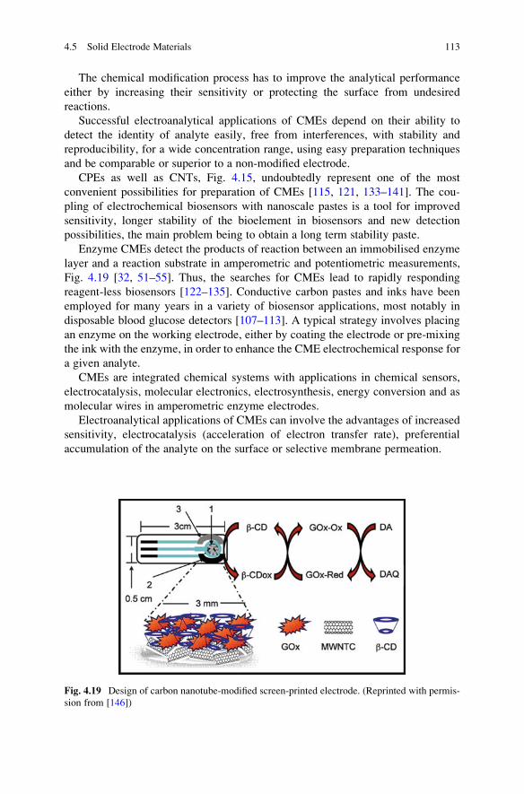
The chemical modification process has to improve the analytical performance
either by increasing their sensitivity or protecting the surface from undesired
reactions.
Successful electroanalytical applications of CMEs depend on their ability to
detect the identity of analyte easily, free from interferences, with stability and
reproducibility, for a wide concentration range, using easy preparation techniques
and be comparable or superior to a non-modified electrode.
CPEs as well as CNTs, Fig. 4.15, undoubtedly represent one of the most
convenient possibilities for preparation of CMEs [115, 121, 133–141]. The cou-
pling of electrochemical biosensors with nanoscale pastes is a tool for improved
sensitivity, longer stability of the bioelement in biosensors and new detection
possibilities, the main problem being to obtain a long term stability paste.
Enzyme CMEs detect the products of reaction between an immobilised enzyme
layer and a reaction substrate in amperometric and potentiometric measurements,
Fig. 4.19 [32, 51–55]. Thus, the searches for CMEs lead to rapidly responding
reagent-less biosensors [122–135]. Conductive carbon pastes and inks have been
employed for many years in a variety of biosensor applications, most notably in
disposable blood glucose detectors [107–113]. A typical strategy involves placing
an enzyme on the working electrode, either by coating the electrode or pre-mixing
the ink with the enzyme, in order to enhance the CME electrochemical response for
a given analyte.
CMEs are integrated chemical systems with applications in chemical sensors,
electrocatalysis, molecular electronics, electrosynthesis, energy conversion and as
molecular wires in amperometric enzyme electrodes.
Electroanalytical applications of CMEs can involve the advantages of increased
sensitivity, electrocatalysis (acceleration of electron transfer rate), preferential
accumulation of the analyte on the surface or selective membrane permeation.
Fig. 4.19 Design of carbon nanotube-modified screen-printed electrode. (Reprinted with permis-
sion from [146])
4.5 Solid Electrode Materials 113

4.6 Conclusion
Solid electrodes for electrochemistry and electroanalysis have been reviewed. The
versatility and low cost of solid electrode technology are responsible for their
continuous development and wide applications in research and in electroanalysis.
Solid electrode materials, by themselves or after modification as modified elec-
trodes, can be used in many configurations. New modifiers and mediators can
enhance the reproducibility and sensitivity of the solid electrode surface and are
leading to new and wider electroanalytical applications for the determination of
pharmaceuticals in their dosage forms and in biological samples.
References
1. Adams RN (ed) (1969) Electrochemistry at solid electrodes. Marcel Dekker, New York
2. Wang J (ed) (2006) Analytical electrochemistry, 3rd edn. Wiley-VCH, New York
3. Kissinger PT, Heineman WR (eds) (1996) Laboratory techniques in electroanalytical Chem-
istry, 2nd edn. Marcel Dekker, New York
4. Smyth MR, Vos JG (eds) (1992) Analytical voltammetry, vol XXVII. Elsevier, Amsterdam
5. Bond AM (1980) Modern polarographic methods in analytical chemistry. Marcel Dekker,
New York
6. Kellner R, Mermet JM, Otto M, Valcarcel M,Widmer HM (eds) (2004) Analytical chemistry,
a modern approach to analytical science, 2nd edn. Wiley-VCH, New York
7. Christian GD (ed) (2004) Analytical chemistry, 6th edn. Wiley, New Jersey
8. Bard AJ, Faulkner LR (2001) Electrochemical methods, fundamentals and applications,
2nd edn. Wiley, New York
9. Brett CMA, Oliveira-Brett AM (eds) (1993) Electrochemistry, principles, methods and appli-
cations. Oxford University Press, New York
10. Branina KH, Neyman E (1993) Electroanalytical stripping methods. In: Winefordner JD
(ed) Chemical analysis: a series of monographs an analytical chemistry and its applications,
vol 126. Wiley, New York
11. Hart JP (ed) (1990) Electroanalysis of biologically important compounds. Ellis Harwood,
New York
12. Trasatti S (ed) (1980) Electrodes of conductive metallic oxides, Part A. Elsevier, Amsterdam
13. Wang J (ed) (1988) Electroanalytical techniques in clinical chemistry and laboratory medi-
cine. VCH, New York
14. Koryta J, Dvorak J, Kavan L (eds) (1993) Principles of electrochemistry, 2nd edn. Wiley,
New York
15. Pierson HO (ed) (1993) Handbook of carbon, graphite, diamond and fullerenes Properties,
processing and applications. Noyes, New Jersey
16. Meyyapan M (ed) (2005) Carbon nanotubes, science and applications. CRC, London
17. Bagotsky VS (ed) (2006) Fundamentals of electrochemistry, 2nd edn. Wiley-Interscience,
New Jersey
18. Uslu B, Ozkan SA (2007) Anal Lett 40:817–853
19. Uslu B, Ozkan SA (2007) Comb Chem High Throughput Screen 10:495–513
20. Greef R, Peat R, Peter LM, Pletcher D, Robinson J (1985) Instrumental methods in electro-
chemistry. Ellis Horwood Ltd, New York
21. Solomen E (1987) Z Phys Chem 24:55–62
22. Angerstein-Kozlowska H, Conway BE, Sharp WVA (1973) J Electroanal Chem 43:9–36
114 4 Solid Electrodes in Drug Analysis

23. Hamelin A (1985) Double layer properties at sp and sd metal single–crystal electrodes. In:
Conway BE, White RE, Bockris JO (eds) Modern aspects of electrochemistry. Plenum,
New York
24. Lipson H, Stokes AR (1942) Math Phys Sci 181:101–105
25. Bas B, Piech R, Niewiara E, Ziemnicka M, Stobierski L, Kubiak WW (2008) Electroanalysis
20:1655–1660
26. Bauman F, Shain I (1957) Anal Chem 29:303–306
27. Yang ZP, Enquist I, Kauffmann JM, Liedberg B (1996) Langmuir 12:1704–1707
28. He P, Ye J, Fang Y, Anzai J, Osa T (1997) Talanta 44:885–890
29. Wang J, Lu J, Hocevar S, Farias P, Ogorevc B (2000) Anal Chem 72:3218–3222
30. Wang J (2005) Electroanalysis 17:1341–1346
31. Zoski CG (ed) (2007) Handbook of electrochemistry, 1st edn. Elsevier, Amsterdam
32. Kalcher K, Svancara I, Metelka R, Vytras K, Walcarius A (2008) Heterogeneous carbon
electrochemical sensors. In: Grimes CA, Dickey EC, Pishko MV (eds) Encyclopedia of
sensors. American Scientific Publishers, New York
33. Kalcher K (1990) Electroanalysis 2:419–433
34. Adams RN (1958) Anal Chem 30:1576–1576
35. Olsen C, Adams RN (1960) Anal Chim Acta 22:528–536
36. Urbaniczky C, Lundstorm K (1984) J Electroanal Chem 176:169–182
37. Rice M, Galus Z, Adams RN (1983) J Electroanal Chem 143:89–102
38. Radi AE, Abd-Elghany N, Wahdan T (2007) Chem Pharm Bull 55:1379–1382
39. Kuwana T, French WG (1964) Anal Chem 36:241–242
40. Bard AJ, Faulkner LR (2001) Electrochemical Methods 13:560
41. Chiorcea AM, Oliveira-Brett AM (2004) Bioelectrochem 63:229–232
42. Schultz FA, Kuwana T (1965) J Electroanal Chem 10:95–103
43. Bauer D, Gaillochet MP (1974) Electrochim Acta 19:597–606
44. Lamache M, Bauer D (1979) Anal Chem 51:1320–1322
45. Maleki H, Cojocaru CD, Brett CMA, Jenkins GM, Selman JR (1998) J Electrochem Soc 145:
721–730
46. Jenkins GM, Kawamura K (1971) Nature 231:175–176
47. Harris PJF (ed) (1999) Carbon nanotubes and related structures, New materials for the
twenty first century. Cambridge University Press, United Kingdom
48. Harris PJF (2005) Crit Rev Solid State Mater Sci 30:235–253
49. Trinidad P, Ponce de Le�on C, Walsh FC (2006) Electrochim Acta 52:604–613
50. Friedrich JM, Ponce-de-Leon C, Reade GW, Walsh FC (2004) J Electroanal Chem 561:
203–217
51. Svancara I, Vytras K, Kalcher K, Walcarius A, Wang J (2009) Electroanalysis 21:7–28
52. Zima J, Svancara I, Barek J, Vytras K (2009) Crit Rev Anal Chem 39:204–227
53. Svancara I, Walcarius A, Kalcher K, Vytras K (2009) Cent Eur J Chem 7:598–656
54. Svancara I, Vytras K, Barek J, Zima J (2001) Crit Rev Anal Chem 31:311–345
55. Vytras K, Svancara I, Metelka R (2009) J Serb Chem Soc 74:1021–1033
56. Jarbawi TB, Heineman WR (1986) Anal Chim Acta 186:11–19
57. Brunetti B, Ugo P, Moretto LM, Martin CR (2000) J Electroanal Chem 491:166–167
58. Kalcher K, Kauffmann JM, Wang J, Svancara I, Vytras K, Yang Z (1995) Electroanalysis
7:5–22
59. Wilson GS (2002) Bioelectrochemistry. In: Bard AJ, Stratmann M (eds) Encyclopedia of
electrochemistry, vol 9. Wiley-VCH, Weinheim
60. Sebkova S, Navratil T, Kopanica M (2005) Anal Lett 38:1747–1758
61. Gaylor VF, Conrad AL, Landerl JH (1957) Anal Chem 29:224–228
62. Elving PJ, Smith DL (1960) Anal Chem 32:1849–1854
63. Kroto HW, Heath JR, O’Brien SC, Curl RF, Smalley RE (1985) Nature 318:162–163
64. Guldi DM, Martun N (2010) Carbon nanotubes and related structures: synthesis, character-
ization, functionalization, and applications. Wiley-VCH, GmbH & Co. KGaA, Weinheim
References 115

65. Edmonds T (1985) Anal Chim Acta 175:1–22
66. Huffman ML, Venton BJ (2008) Electroanalysis 22:2422–2428
67. Howell JO, Wightman RM (1984) Anal Chem 56:524–529
68. Engstrom RC, Wightman RM, Kristensen EW (1988) Anal Chem 60:652–656
69. Besenhard JO, Schultze A, Schur K, Jannakoudakis PD (1991) Preparation of voltammetric
and potentiometric carbon fibremicroelectrodes. In:MontenegroMI, Queir�osMA,Daschbach
JL (eds)Microelectrodes: theory and applications, NATOASI Series E. Springer, Netherlands
70. Kuras A, Gutmaniene N (2000) J Neurosci Meth 96:143–146
71. Iijima S (1991) Nature 354:56–58
72. Sherigara BS, Kutner W, D’Souza F (2003) Electroanalysis 15:753–772
73. Gogotsi Y (ed) (2006) Carbon nanomaterials. CRC Taylor Francis Group, New York
74. Dai H (2002) Acc Chem Res 35:1035–1044
75. Lawrence NS, Deo RD, Wang J (2005) Electroanalysis 17:65–72
76. Merkoci A (2006) Microchim Acta 152:157–174
77. Trojanowicz M (2006) TrAC Trends Anal Chem 25:480–489
78. Wang J (2005) Electroanalysis 17:7–14
79. Iijima S, Ichihashi T (1993) Nature 363:603–605
80. Dr. Robert R. Johnson http://astro.temple.edu/~rjohnson
81. Barsan MM, Carvalho RC, Zhong Y, Sun X, Brett CMA (2012) Electrochim Acta 85:
203–209
82. Li J, Cassell A, Delzeit L, Han J, Meyyappan M (2002) J Phys Chem B 106:9299–9305
83. Zhao Q, Gan Z, Zhuang Q (2002) Electroanalysis 14:1606–1607
84. Ge M, Sattler K (1994) Appl Phys Lett 65:2284–2286
85. Kwon YK, Lee YH, Kim SG, Jund P, Tomanek D, Smalley RE (1997) Phys Rev Lett 79:
2065–2068
86. Eftekhari A (ed) (2008) Nanostructured materials in electrochemistry. Wiley-VCH Verlag
GmbH & Co KGaA, Weinheim
87. Loiseau A, Launois P, Petit P, Roche S, Salvetat JP (eds) (2006) Understanding carbon
nanotubes. Springer, Berlin
88. Jorio A, Dresselhaus MS, Dresselhaus G (eds) (2008) Carbon nanotubes, advanced topics in
the synthesis, structure, properties and applications. Springer, Berlin
89. Hodes G (ed) (2001) Electrochemistry of nanomaterials. Wiley-VCH Verlag GmbH,
Weinheim
90. Balasubramanian K, Burghard M (eds) (2010) Carbon nanotubes, methods and protocols.
Humana Press a part of Springer Science + Business Media, Totowa, NJ
91. Enache TA, Chiorcea-Paquim AM, Fatibello-Filho O, Oliveira-Brett AM (2009)
Electrochem Commun 11:1342–1345
92. Yamanaka S, Watanabe H, Masai S, Takeuchi D, Okushi H, Kajimura K (1998) Jpn J Appl
Phys 37:L1129
93. Sakharove AY, Peleskov YV, Quarto FD, Piazza S, Sunseri C, Teremetskaya IG, Varnin VP
(1995) J Electrochem Soc 142:2704–2709
94. LawrenceNS,PagelsM,MeredithA, JonesTGJ,Hall CE, PicklesCSJ,GodfriedHP,BanksCE,
Compton RG, Jiang L (2006) Talanta 69:829–834
95. Ramamurti R, Becker M, Schuelke T, Grotjohn T, Reinhard D, Swain G, Asmussen J (2008)
Diam Relat Mater 17:481–485
96. Lowe MA, Fischer AE, Swain GM (2006) J Electrochem Soc 153:B506–B511
97. Kapalka A, F�oti G, Comninellis C (2009) Electrochim Acta 54:2018–2023
98. Peleskov YV (2002) Russ J Electrochem 38:1275–1291
99. Compton RG, Foord JS, Marken F (2003) Electroanalysis 15:1349–1363
100. Fortin E, Chane-Tune J, Delabouglise D, Bouvier P, Livache T, Mailley P, Marcus B,
Mermoux M, Petit JP, Szunerits S, Vieil E (2005) Electroanalysis 17:517–526
101. Codognoto L, Machado SAS, Avaca LA (2003) Diam Relat Mater 33:951–957
102 Rao TN, Fujishima A (2000) Diam Relat Mater 9:384–289
103. Hupert M, Muck A, Wang J, Stotter J, Cvackova Z, Haymond S, Show Y, Swain GM (2003)
Diam Relat Mater 12:1940–1949
116 4 Solid Electrodes in Drug Analysis

104. Xu J, Granger MC, Chen Q, Lister TE, Strojek JW, Swain GM (1997) Anal Chem 69:
591A–597A
105. Oliveira SCB, Oliveira-Brett AM (2010) J Electroanal Chem 648:60–66
106. Creanga C, Serban S, Pittson RW, El Murr N (2011) “No Calibration” type sensor in routine
amperometric bio-sensing—an example of a disposable hydrogen peroxide biosensor, bio-
medical engineering. In: Serra PA (ed) Biosensors-emerging materials and applications.
InTech, Croatia
107. Dominguez Renedo O, Alonso-Lomillo MA, Arcos Martinez MJ (2007) Talanta 73:202–219
108. Branina KZ, Kositzina AN, Ivanova A (2007) Electrochemical sensor analysis. In: Alegret S,
Merkoci A, Barcelo D (eds) Comprehensive analytical chemistry, 1st edn. Elsevier,
Amsterdam
109. Sljukic B, Malakhova NA, Branina KZ, Banks CE, Compton RG (2006) Electroanalysis 18:
928–930
110. Hart JP, Crew A, Crouch E, Honeychurch KC, Pemberton RM (2004) Anal Lett 37:789–830
111. Hart JP, Wring SA (1997) TrAC-Trends Anal Chem 16:89–103
112. Honeychurch KC, Hart JP (2003) TrAC Trends Anal Chem 22:456–469
113. Choi JY, Seo K, Cho SR, Oh JR, Kahng SH, Park J (2001) Anal Chim Acta 443:241–247
114. Radi A-E, Eissa A, Nassef HM (2014) J Electroanal Chem 717–718:24–28
115. Svancara I, Kotzian P, Bartos M, Vytras K (2005) Electrochem Commun 7:657–662
116. Materon EM, Wong A, Klein SI, Liu J, Sotomayor MDPT (2015) Electrochim Acta 158:
271–276
117. Hart JP, Wring SA (1994) Electroanalysis 6:617–624
118. Brett AM, Serrano SH, Gutz IG, La-Scalea MA (1997) Electroanalysis 9:110–114
119. Demetriades D, Economou A, Volugaropous A (2001) Anal Chim Acta 43:434–441
120. Murray RW (1981) Chemically modified electrodes. In: Bard AJ (ed) Electroanalytical chem-
istry. CRC, Boca Baton, FL
121. Eggins BR (ed) (2002) Chemical sensors and biosensors. Wiley-VCH, New York
122. Radi AE (2006) Curr Pharm Anal 2:1–8
123. Durst RA, Baumer AJ, Murray RW, Buck RP, Andrieux CP (1997) Pure Appl Chem 69:
1317–1323
124. Arrigan DW (1994) Analyst 119:1953–1966
125. Faulkner LR (1989) Electrochim Acta 34:1699–1706
126. Guadelupe AR, Abruna HD (1985) Anal Chem 57:142–149
127. Murray RW (1980) Acc Chem Res 13:135–141
128. Murray RW (1992) Molecular design of electrode surfaces, vol 22. Wiley and Sons,
New York
129. Murray RW (1984) Chemically modified electrodes. In: Bard AJ (ed) Electroanalytical chem-
istry, A series of advances. Marcel Dekker, New York
130. Nikolelis DP, Krull UJ (1993) Electroanalysis 5:539–545
131. Odashima K, Sugawara M, Umezawa Y (1991) Trends Anal Chem 10:207–215
132. Radi A (2010) Comb Chem High Throughput Screen 13:728–752
133. Fujihira M, Rusling JF, Rubinstein I (2007) Modified electrodes. In: Bard AJ, Stratmann M
(eds) Encyclopedia of electrochemistry, vol 10. Wiley-VCH, Weinheim
134. Stradiotto NR, Yamanaka H, Zanoni MVB (2003) J Braz Chem Soc 14:159–173
135. Zhang JD, Oyama M (2004) J Microchem 78:217–222
136. Zhao GH, Qi Y, Tian Y (2006) Electroanalysis 18:830–834
137. Wang J, Tian B, Rogers KR (1998) Anal Chem 70:1682–1685
138. Baldwin RP, Thomsen KN (1991) Talanta 38:645–652
139. Walcarius A (2001) Electroanalysis 13:701–718
140. Kauffmann JM, Guiberteau A (1994) Quim Anal 13:169–175
141. Wang J (1991) Electroanalysis 3:255–259
142. Budnikov GK, Labuda J (1992) Russ Chem Rev 61:1491–1514
143. Kutner W, Wang J, L’Her M, Buck RP (1998) Pure Appl Chem 70:1301–1318
References 117

144 Pauliukaite R, Ghica ME, Barsan MM, Brett CMA (2010) Anal Lett 43:1588–1608
145. Pierre AC (2004) Biocatal Biotransform 22:145–170
146. Alarc�on G, Guix M, Silva WC, Ramırez AM, Palomar M, Merkoci A (2010)
Biosens Bioelectron 26:1768–1773
118 4 Solid Electrodes in Drug Analysis