electro industries · electro industries g a u g e t e c h dmva 100 solid state dual...
TRANSCRIPT

ELECTRO INDUSTRIES G A U G E T E C H
DMVA 100SOLID STATE DUAL DISPLAY/THREE-PHASE DIGITAL VOLTS-AMPS MONITOR
DMVA 100-FSOLID STATE DUAL DISPLAY/THREE-PHASE VOLTS-AMPS-FREQUENCY MONITOR
1800 Shames DriveWestbury, NY 11590
Tel: (516) 334-0870 Fax: (516) 338-4741
USER'S INSTALLATION & OPERATION MANUAL ANDUSER’S PROGRAMMING MANUALVERSION 2.2/9-97

TABLE OF CONTENTS
I N S T A L L A T I O N & O P E R A T I O N
CHAPTER 1 MECHANICAL INSTALLATION 1w Installation of the DMVA100 with K-110 Option for limited space
conditions1
w Standard Installation of the DMVA100 1w Standard Cutout of DMVA100 2w Communication Converter Installation or DC Output 2
CHAPTER 2 ELECTRICAL INSTALLATION 3Section 2.1 Connecting the Current Circuit 3
2.2 Connecting Voltage Circuit of Potential Transformer 32.3 Selecting the Voltage Fuses 32.4 Connection to the Main Power Supply 42.5 Electrical Connection Installation 4
w 3-Phase, 3-Wire Delta with Direct Voltage and CTs 5w 3-Phase, 3-Wire Open Delta with 2 CTs and 2 PTs 5w 3-Phase, 3-Wire Open Delta with 3 CTs and 2 PTs 6w 3-Phase, 4-Wire Wye with Direct Voltage and CTs 6w 3-Phase, 4-Wire Wye with CTs and PTs 7w Single Phase System 7w Dual Phase System 8
2.6 Relays and Protection 8
CHAPTER 3 COMMUNICATION INSTALLATION 10Section 3.1 RS-232C 10
3.2 RS-485 103.3 Network of Instruments and Long Distance Communication 16
CHAPTER 4 DMVA100: OVERVIEW 17Section 4.1 Accessing Max/Min Values 17
4.2 Resetting Values 184.3 Accessing the LM1/LM2 Set Limits 194.4 Voltage Phase Reversal and Imbalance 194.5 Printing Operating Data 204.6 Printing Programming Data 214.7 Accessing LED Test 224.8 Accessing Firmware Versions 22
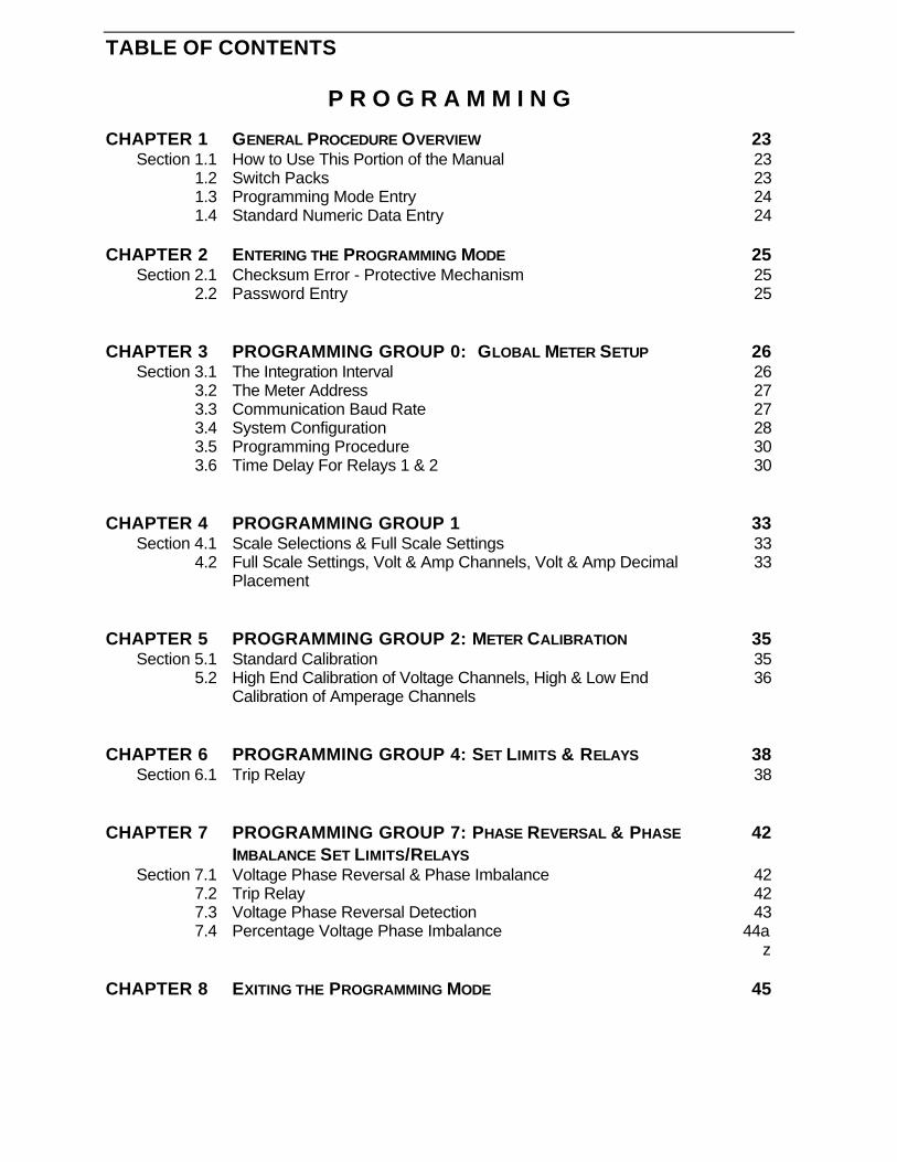
TABLE OF CONTENTS
P R O G R A M M I N G
CHAPTER 1 GENERAL PROCEDURE OVERVIEW 23Section 1.1 How to Use This Portion of the Manual 23
1.2 Switch Packs 231.3 Programming Mode Entry 241.4 Standard Numeric Data Entry 24
CHAPTER 2 ENTERING THE PROGRAMMING MODE 25Section 2.1 Checksum Error - Protective Mechanism 25
2.2 Password Entry 25
CHAPTER 3 PROGRAMMING GROUP 0: GLOBAL METER SETUP 26Section 3.1 The Integration Interval 26
3.2 The Meter Address 273.3 Communication Baud Rate 273.4 System Configuration 283.5 Programming Procedure 303.6 Time Delay For Relays 1 & 2 30
CHAPTER 4 PROGRAMMING GROUP 1 33Section 4.1 Scale Selections & Full Scale Settings 33
4.2 Full Scale Settings, Volt & Amp Channels, Volt & Amp DecimalPlacement
33
CHAPTER 5 PROGRAMMING GROUP 2: METER CALIBRATION 35Section 5.1 Standard Calibration 35
5.2 High End Calibration of Voltage Channels, High & Low EndCalibration of Amperage Channels
36
CHAPTER 6 PROGRAMMING GROUP 4: SET LIMITS & RELAYS 38Section 6.1 Trip Relay 38
CHAPTER 7 PROGRAMMING GROUP 7: PHASE REVERSAL & PHASE
IMBALANCE SET LIMITS/RELAYS
42
Section 7.1 Voltage Phase Reversal & Phase Imbalance 427.2 Trip Relay 427.3 Voltage Phase Reversal Detection 437.4 Percentage Voltage Phase Imbalance 44a
z
CHAPTER 8 EXITING THE PROGRAMMING MODE 45

INSTALLATION & OPERATION
CHAPTER 1MECHANICAL INSTALLATION
1
Electro Industries / GAUGETECH
DMVA 100: Installation & Operation
The following diagrams display the various possible DMVA100 mechanical installations and CommunicationConverter installation.
NOTE: ALL MEASUREMENTS ARE IN INCHES.
4.375SQ. .890
2.45
2.425
.336
.714(4) 8-32 SCREWS
4.50SQ.
36" CABLE
.80
3.00
5.00
MAX/MIN
LIMITS
Elec t r o Indus t r i e sEle c t r o Indus t r i e s
AC VOLTS
NCBA
AC AMPS
MAX MIN LM2LM1
AN
BN
CN
AB
BC
CA
VOLTSPRINT
AMPSPHASENEXTPROG
Diagram 1.1 Installation of the DMVA100 with K-110 Option for limited space conditions.
4.375.890
2.0
SQ.
4.50SQ.
3.0
Electro Industr iesElectro Industr ies
MAX/MIN
LIMITS
AC VOLTS
NCBA
AC AMPS
MAX MIN LM2LM1
AN
BN
CN
AB
BC
CA
VOLTSPRINT
AMPSPHASE
NEXTPROG
Chapter 1 Mechanical Installation
2
Electro Industries / GAUGETECH
DMVA 100: Installation & Operation
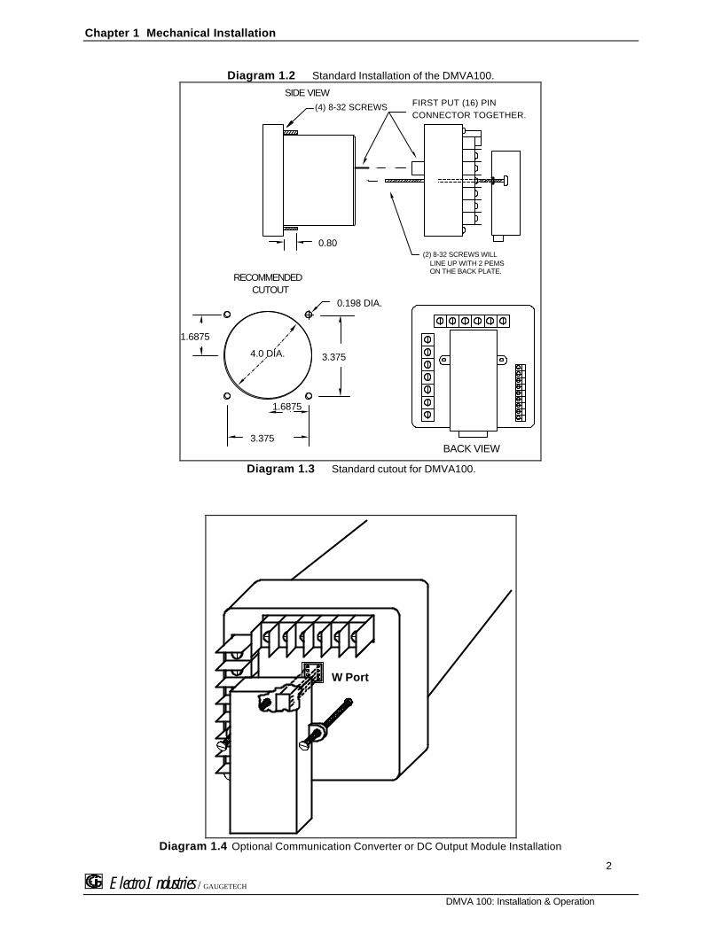
Diagram 1.2 Standard Installation of the DMVA100.
FIRST PUT (16) PIN CONNECTOR TOGETHER.
(2) 8-32 SCREWS WILL
SIDE VIEW
0.80
(4) 8-32 SCREWS
LINE UP WITH 2 PEMSON THE BACK PLATE.
0.198 DIA.
3.375
3.375
4.0 DIA.
1.6875
1.6875
RECOMMENDEDCUTOUT
BACK VIEW
Diagram 1.3 Standard cutout for DMVA100.
W Port
Diagram 1.4 Optional Communication Converter or DC Output Module Installation

Chapter 1 Mechanical Installation
3
Electro Industries / GAUGETECH
DMVA 100: Installation & Operation
NOTE: CAREFULLY LINE UP THE GUIDE SCREW AND 8 PIN PORT CONNECTOR TO PREVENT PINS FROM BREAKING.

CHAPTER 2ELECTRICAL INSTALLATION
3
Electro Industries / GAUGETECH
DMVA 100: Installation & Operation
2.1 CONNECTING THE CURRENT CIRCUIT
The cable used for the current should be installed at 600V AC minimum. The cable connector should be rated at 6Amps or greater, and it should have a cross-sectional area of 16 AWG.
The current transformers should be mounted as close as possible to the meter. The following table gives themaximum recommended distances for various CT sizes, assuming the connection is made via 16 AWG cable.
CT SIZE (VA) MAXIMUM DISTANCE (CT TO DMMS)2.5 VA 10 FEET
5.0 VA 15 FEET
7.5 VA 30 FEET
10.0 VA 40 FEET
15.0 VA 60 FEET
30.0 VA 120 FEET
WARNING: DO NOT LEAVE SECONDARY OF CT WHEN PRIMARY CURRENT IS FLOWING. THIS MAY CAUSE HIGH VOLTAGE
WHICH OVERHEATS THE SECONDARY OF THE CT. IF THE CT IS NOT CONNECTED , PROVIDE A SHORTING BLOCK ON THE
SECONDARY OF THE CT.
2.2 CONNECTING VOLTAGE CIRCUIT OF POTENTIAL TRANSFORMER
For proper operation, the voltage connection must be maintained. If an error occurs, such as mistaking Line A forLine B, a PH message appears, indicating a Phase Reversal (see Phase Imbalance and Reversal).
The cable required to terminate the voltage sense circuit should have an insulation rating greater than 600V ACand a current rating greater than 0.1 A.
2.3 SELECTING THE VOLTAGE FUSES
We recommend using fuses, although connection diagrams do not show them. Slow blow, 200 mA rating fusesshould be used.
The maximum voltage DMVA100 can handle 150V phase to neutral. If Suffix -G is added to the model number, themaximum voltage to be used is 300V phase to neutral.
2.4 CONNECTION TO THE MAIN POWER SUPPLY
The DMVA100 requires a separate power supply connection. Listed are the 5 different power supply options andcorresponding.
NOTE: FOR DC-POWERED UNITS POLARITY MUST BE OBSERVED . AN EARTH TO GROUND CONNECTION TO CHASSIS IS MANDATORY
FOR NORMAL OPERATION (TERMINAL 3). DO NOT GROUND THE UNIT THROUGH THE NEGATIVE OF THE DC SUPPLY . SEPARATE
GROUNDING IS REQUIRED .
POWER SUPPLY OPTIONS SUFFIXES CURRENT120V AC NO SUFFIX .1 AAC
240V AC A .05 AAC
24V DC D .5 ADC
48V DC D1 .25 ADC
125V DC D2 .1 ADC

Chapter 2 Electrical Installation
4
Electro Industries / GAUGETECH
DMVA 100: Installation & Operation

Chapter 2 Electrical Installation
5
Electro Industries / GAUGETECH
DMVA 100: Installation & Operation
2.5 ELECTRICAL CONNECTION INSTALLATION
Choose the diagram that best suits your application and maintain the polarity. Follow the outlinedprocedure to verify correct connection.
NOTE: THE NEUTRAL READING IS CALCULATED FROM THE SUM OF THE 3 PHASES OF CURRENT. HIGH NEUTRAL
CURRENT INDICATES REVERSE CT POLARITY.
LISTING OF CONNECTION DIAGRAMS
NOTE: SEE PHASE REVERSAL IF A MESSAGE OF PH APPEARS AFTER INSTALLATION.
I Three-Phase, Three-Wire System Delta with Direct Voltage and CTs.
II Three-Phase, Three-Wire Open Delta with two CTs and two PTs.(Open Delta System Installation should only be used if the electrical system is a 3-wire OPEN DELTA. Open Delta can be enabled or disabled in Programming Group 0, Function 3.)
III Three-Phase, Three-Wire Open Delta with three CTs and two PTs.(Open Delta System Installation should only be used if the electrical system is a 3-wire OPEN DELTA. Open Delta can be enabled or disabled in Programming Group 0, Function 3.)
IV Three-Phase, Four-Wire System Wye with Direct Voltage and CTs.
V Three-Phase, Four-Wire System Wye with CTs and PTs.
VI Single Phase System
VII Dual Phase System

Chapter 2 Electrical Installation
6
Electro Industries / GAUGETECH
DMVA 100: Installation & Operation
+
-POWER
7
6
5
4
3
2
1
8 9 10 11 12 13
PORT
L1
L
LINEA B C
LOAD
3-PHASE, 3-WIRE DELTA
BACK VIEW
WITH DIRECT VOLTAGE AND CTs
CONTROL
I. Three Phase System
CONTROL +
-
POWER
7
6
5
4
3
2
1
8 9 10 11 12 13
PORT
L1
L
LINEA B C
LOAD
3-PHASE, 3-WIRE OPEN DELTA
BACK VIEW
WITH 2 CTs AND 2 PTs
II. Open Delta PT Connection Special programming required.

Chapter 2 Electrical Installation
7
Electro Industries / GAUGETECH
DMVA 100: Installation & Operation
+
-
POWER
7
6
5
4
3
2
1
8 9 10 11 12 13
PORT
L1
L
LINEA B C
LOAD
3-PHASE, 3-WIRE OPEN DELTA
BACK VIEW
WITH 3 CTs AND 2 PTs
III. Open Delta PT Connection Special programming required.
+
-POWER
7
6
5
4
3
2
1
8 9 10 11 12 13
PORT
L1
L
LINEN A B C
LOAD
3-PHASE, 4-WIRE WYE
BACK VIEW
WITH DIRECT VOLTAGE AND CTs
CONTROL
IV. Three Phase System

Chapter 2 Electrical Installation
8
Electro Industries / GAUGETECH
DMVA 100: Installation & Operation
7
6
5
4
3
2
1
8 9 10 11 12 13
LINE
N A B C
LOAD
3-PHASE, 4-WIRE WYE
L1
L2POWER
+
-
PORT
BACK VIEW
WITH CTs AND PTs
V. Three Phase System Wye System with PTs
+
-
POWER
7
6
5
4
3
2
1
8 9 10 11 12 13
PORT
L2
L1
LINEA
LOAD
SINGLE-PHASE
BACK VIEW
WITH CT AND PT CONNECTION
VI. Single-Phase System

Chapter 2 Electrical Installation
9
Electro Industries / GAUGETECH
DMVA 100: Installation & Operation
7
6
5
4
3
2
1
8 9 10 11 12 13
LINE
A B
LOAD
DUAL-PHASE
L1
L2POWER
+
-
PORT
BACK VIEW
WITH CTs AND PTs
VII. Dual-Phase System
2.6 RELAYS AND PROTECTION
NOTE: THIS SECTION IS APPLICABLE ONLY IF THE -NL RELAY OPTION WAS ORDERED .
The DMVA100's allows the user to access a variety of relay options through the programming mode. The relayoption package consists of two relays, which can be dedicated to alarm or communication (or both).
TIME DELAY: Sets off the alarm, alerting the user that an out-of-limits condition occurred during the defined timelimit. The time delay can be programmed for any desirable duration.
If the relays are dedicated to communication, there are two different modes:
§ Lock ON Relay will not be affected by any alarm condition.§ Lock OFF Relay will not be affected by any alarm condition.
If the relays are used for communication and alarm, there are four different modes:
§ Lock ON Relay stays on regardless of any alarm condition.§ Lock OFF Relay stays off regardless of any alarm condition.§ Free ON Relay turns on unless other conditions force it off.§ Free OFF Relay turns off unless other conditions force it on.

Chapter 2 Electrical Installation
10
Electro Industries / GAUGETECH
DMVA 100: Installation & Operation
Figure 2.1 - Relay Connection
Close-up of the relays on the rear panel. The relaysshown are in the NOT energized state. (Form C relays,rated 250V, 5A, 2 each)
20
21
22
23
24
25
N.O.
N.C.
COM
N.O.
N.C.
COM
ALARM #1
ALARM #2
THE INSTRUMENT CAN BE PROGRAMMED TO DETECT TWO ALARM LEVELS FOR THE FOLLOWING FUNCTIONS:
§ LM1/LM2 Voltage AN, BN, CN, AB, BC, CA
§ LM1/LM2 Current A, B, C, N
§ Voltage Imbalance (One level only)
§ Voltage Phase Reversals (One level only)

CHAPTER 3COMMUNICATION INSTALLATION
10
Electro Industries / GAUGETECH
DMVA 100: Installation & Operation
3.1 RS-232C
All DMVA100’s can be equipped with: the EIA RS-232C or the EIA RS-485.
RS-232C communication links a single instrument with a computer. Its capability is capable up to 100 feet.A standard 9-pin female serial port connector mounts on the instrument for direct connection to a computerwith a 9-pin cable.
NOTE: ONLY THREE PINS ARE USED IN RS-232C. (See Figure 3.1).
COMMUNICATION
CONVERTER
RS-232 COMMUNICATION CONNECTION
CONNECTION FOR DB-9 FEMALEPIN 2 - RECEIVE OF THE HOST/COMPUTER
PIN 3 - TRANSMIT OF THE HOST/COMPUTER
PIN 5 - GROUND OF THE HOST/COMPUTER
DB-9 CONNECTOR
5 4 3 2 1
9 8 7 6
7
6
5
4
3
2
1
20
21
22
* A DIRECT PIN-TO-PIN CABLE CAN BE USED.
23
24
25
27
26
28
8 9 10 11 12 13
Model SF-232DB
NO NULL-MODEM IS REQUIRED.
Figure 3.1 RS-232C Communication Connection Installation
NOTE: TO AVOID GROUND LOOPS, THE NEUTRAL AND SAFETY GROUND (PIN 3) SHOULD BE CONNECTED TOGETHER AT
ONLY ONE POINT.
3.2 RS-485
NOTE: THIS SECTION APPLIES ONLY IF A COMMUNICATION OPTION WAS ORDERED.
Each DMVA100 has an unique address up to four digits long. This allows the user to communicate with upto 10,000 instruments. Standard baud rates are available up to 4800 baud. To select the proper baud rate,apply the following rules:
The unit operates up to 4800. For a smaller number of instruments over a long distance,use a lower baud. Optimal recommended baud rate is 1200 baud if noisy conditions exist.

Chapter 3 Communication Installation
11
Electro Industries / GAUGETECH
DMVA 100: Installation & Operation
RS-485 is used to parallel multiple instruments on the same link. Its operating capability is up to 4000 feet.• When only 2 wires are used (on the RS-485), the link can include up to 30 instruments, (Figure 3.2).• When using all 4 wires, the link can include up to 60 instruments, (Figure 3.3).
RS-485 Hookup Diagram(2 wire) Half Duplex
Electro IndustriesRS-485 to RS232Communication
Converter
(-)(+)
RS-2
32
IBM CompatibleDrawing By: ENGINEERING
Date: August 21, 1997
Electro Industries / GaugeTech
RS-4
85
RT
RT
Figure 3.2 2-Wire RS-485 Communication Connection Installation Half Duplex

Chapter 3 Communication Installation
12
Electro Industries / GAUGETECH
DMVA 100: Installation & Operation
Drawing By: ENGINEERING
Date: August 21, 1997
Electro Industries / GaugeTech
Electro IndustriesRS-485 to RS232Communication
Converter
RS-2
32RS
-485
RS-485 Hookup Diagram(2 wire) Half Duplex(Closed Loop)
Figure 3.3 4-Wire RS-485 Communication Connection Installation Half Duplex (Closed Loop)

Chapter 3 Communication Installation
13
Electro Industries / GAUGETECH
DMVA 100: Installation & Operation
RS-485 Hookup Diagram(2 wire) Half Duplex Detail View
Gnd
R+T+
R-
T-
G R+ T+ R- T- G R+ T+ R- T-
RS-485Communications
Port
Model#SF485DB
RS-485Communications
Port
Model#SF485DB
Electro IndustriesRS-485 to RS232Communication
Converter
RS
-48
5 P
ort
Drawing By: ENGINEERING
Date: August 21, 1997
Electro Industries / GaugeTech
RT
Figure 3.4 2-Wire RS-485 Communication Connection Installation Half Duplex Detailed View

Chapter 4 Communication Installation
Electro Industries / GAUGETECH
DMMS 300+: Installation & Operation
14
RS-485 Hookup Diagram(4 wire) Full Duplex
Electro IndustriesRS-485 to RS232Communication
Converter
T+ T-R-R+
RS
-232
RS
-485
IBM CompatibleDrawing By: ENGINEERING
Date: August 21, 1997
Electro Industries / GaugeTech
Figure 3.3 4-Wire RS-485 Communication Connection Installation Full Duplex

Chapter 3 Communication Installation
Electro Industries / GAUGETECH
DMVA 100: Installation & Operation
16
<==32 UNITS==>
<==32 UNITS==>
32 TRANSPONDER COMPUTER
DEVICE
DEVICE
DEVICE
DEVICE
RS 485TRANSPONDER
RS 485TRANSPONDER
Figure 3.4 2-Wire RS-485 Communication Installation Connection with Transponder
<==32 UNITS==>
<==32 UNITS==>
32 TRANSPONDER COMPUTER
DEVICE
DEVICE
DEVICE
DEVICE
RS 485TRANSPONDER
RS 485TRANSPONDER
Figure 3.5 4-Wire RS-485 Communication Installation Connection with Transponder
3.3 NETWORK OF INSTRUMENTS AND LONG DISTANCE COMMUNICATION
The RS-485 Transponder is required for a large network of instruments.
• In a two-wire connection, a maximum of 900 instruments can be included in the same network, (Figure 3.4).
• Meanwhile, in a four-wire connection, a maximum of 3600 instruments can be included in the same link,(Figure 3.5).
Chapter 3 Communication Installation
Electro Industries / GAUGETECH
DMVA 100: Installation & Operation
17
Use modems (dedicated or dial-up) when the instruments are located at great distances. However, set themodem to auto answer at the recommended value of 1200 baud rate if noise conditions exist. Also, flow controlmust be disabled.

CHAPTER 4DMVA 100 OVERVIEW
17
Electro Industries / GAUGETECH
DMVA 100: Installation & Operation
The DMVA100 measures 10 electrical parameters. Values for each parameter are accessed through the keypadon the meter's front panel (See Figure 4.1).
VOLTS AMPS
A-N A
B-N B
C-N C
A-B N
B-C
C-A
BWHEN THE DESIRED FUNCTION IS CHOSEN,THE PHASE/NEXT BUTTON SELECTS THEVOLT AND AMP PHASES.
CA GLOWING ANNUNCIATOR
CURRENTLY DISPLAYED.INDICATES THE VALUE
ATHE VOLTAGE AND AMPERAGEFUNCTIONS ARE ACCESSSED BYPRESSING THE APPROPRIATE BUTTON.
MAXIMUM, MINIMUM,D
PRESS THE
VALUES.
BUTTON TO ACCESSMAX/MIN/LIMITS
LIMIT 1, OR LIMIT 2
MAX/MIN
LIMITS
AC VOLTS
AC AMPS
FREQUENCY
NCBA
MAX
MIN
Elec t r o Indus t r i e sEle c t r o Indus t r i e s
A
N
B
N
C
N
A
B
B
C
C
A
LM2
LM1
NEXT
PHASEVOLTS AMPSPROG
EFREQUENCY MEASUREMENT
ORDERED WITH OPTION -F.
AVAILABLE WHEN
Figure 4.1The DMVA100 front panel with display and keypad with option -F.
4.1 ACCESSING MAX/MIN VALUES FROM OPERATING MODE
The max/min values represent the highest and lowest average demand over a user programmable time period,know as the INTEGRATION INTERVAL. The readings are calculated using a rolling average technique. Eachsecond, a new reading is used to calculate the max/min and the last reading of the interval is dropped.
ðð To ACCESS MAX/MIN VALUES, follow these steps:
E l e c t r o I n d u s t r i e sE l e c t r o I n d u s t r i e s
MAX/MIN
LIMITS
AC VOLTS
NCBA
AC AMPS
MAX MIN LM2LM1
AN
BN
CN
AB
BC
CA
VOLTSPRINT
AMPSPHASENEXTPROG
E l e c t r o I n d u s t r i e sE l e c t r o I n d u s t r i e s
MAX/MIN
LIMITS
AC VOLTS
NCBA
AC AMPS
MAX MIN LM2LM1
AN
BN
CN
AB
BC
CA
VOLTSPRINT AMPS PHASENEXTPROG
E l e c t r o I n d u s t r i e sE l e c t r o I n d u s t r i e s
MAX/MIN
LIMITS
AC VOLTS
NCBA
AC AMPS
MAX MIN LM2LM1
AN
BN
CN
AB
BC
CA
VOLTSPRINT
AMPSPHASENEXTPROG

Chapter 4 DMVA 100 Overview
Electro Industries / GAUGETECH
DMVA 100: Installation & Operation
18
Step 1:a. Press VOLTS to select the VOLTScategory.
Step 2:a. Press PHASE/ NEXT until thedesired phase is selected.
Step 3:a. Press MAX/MIN/ LIMITS:ððONCE for max of VOLT A-Nðð TWICE for min of VOLTS A-N
4.2 RESETTING VALUES FROM OPERATING MODE
Use the reset function if a new value is desired. It is available in two different modes:
1. UNPROTECTED MODE: allows quick and easy resetting of max/min values.2. PROTECTED MODE: prevents unauthorized personnel from resetting the max/min.
qq UNPROTECTED RESET
E l e c t r o I n d u s t r i e sE l e c t r o I n d u s t r i e s
MAX/MIN
LIMITS
AC VOLTS
NCBA
AC AMPS
MAX MIN LM2LM1
AN
BN
CN
AB
BC
CA
VOLTSPRINT
AMPSPHASENEXTPROG
E l e c t r o I n d u s t r i e sE l e c t r o I n d u s t r i e s
MAX/MIN
LIMITS
AC VOLTS
NCBA
AC AMPS
MAX MIN LM2LM1
AN
BN
CN
AB
BC
CA
VOLTSPRINT
AMPSPHASENEXTPROG
E l e c t r o I n d u s t r i e sE l e c t r o I n d u s t r i e s
MAX/MIN
LIMITS
AC VOLTS
NCBA
AC AMPS
MAX MIN LM2LM1
AN
BN
CN
AB
BC
CA
VOLTSPRINT
AMPSPHASENEXTPROG
Step 1:a. Press PHASE/NEXT to select thedesired phase.
Step 2:a. Press MAX/MIN/LIMITS:ððONCE for maxðð TWICE for min
Step 3:a. Press PHASE/NEXT to reset.
ðð The display blanks and acheckmark appears, confirmingsuccessful reset.
qq PROTECTED RESET
NOTE: IF THE METER WAS PROGRAMMED TO HAVE A PROTECTED RESET, A PASSWORD MUST BE ENTERED BEFORE ANY READINGS
MAY BE RESET. THE PASSWORD IS 005.
E l e c t r o I n d u s t r i e sE l e c t r o I n d u s t r i e s
MAX/MIN
LIMITS
AC VOLTS
NCBA
AC AMPS
MAX MIN LM2LM1
AN
BN
CN
AB
BC
CA
VOLTSPRINT
AMPSPHASENEXTPROG
E l e c t r o I n d u s t r i e sE l e c t r o I n d u s t r i e s
MAX/MIN
LIMITS
AC VOLTS
NCBA
AC AMPS
MAX MIN LM2LM1
AN
BN
CN
AB
BC
CA
VOLTSPRINT
AMPSPHASENEXTPROG

Chapter 4 DMVA 100 Overview
Electro Industries / GAUGETECH
DMVA 100: Installation & Operation
19
Step 1:a. Press PHASE/NEXT to select the desired phase.
b. Press MAX/MIN/LIMITS:ððONCE for maxðð TWICE for min
Step 2:a. Press PHASE/NEXT to commence the Protectedreset.
ðð The display blanks, three dashes appear in lowerdisplay and digits begin scrolling in upper display.
ðð The password required is 005.
E l e c t r o I n d u s t r i e sE l e c t r o I n d u s t r i e s
MAX/MIN
LIMITS
AC VOLTS
NCBA
AC AMPS
MAX MIN LM2LM1
AN
BN
CN
AB
BC
CA
VOLTSPRINT
AMPSPHASENEXTPROG
E l e c t r o I n d u s t r i e sE l e c t r o I n d u s t r i e s
MAX/MIN
LIMITS
AC VOLTS
NCBA
AC AMPS
MAX MIN LM2LM1
AN
BN
CN
AB
BC
CA
VOLTSPRINT
AMPSPHASENEXTPROG
Step 3:a. Press PHASE/NEXT each time the appropriatepassword number appears.
Step 4:ððUpon entering the correct password, the displayblanks and a checkmark appears, confirmingsuccessful reset.
4.3 ACCESSING THE LM1/LM2 SET LIMITS FROM OPERATING MODE
The DMVA100 is designed with two manual set limits. The set limits monitor the instantaneous readings, warningthe user of abnormal conditions. Each limit can detect readings above or below the set level. SET LIMITS: the pointwhen the relay changes position, if the DMVA100 is equipped with the Relay Option (Suffix -NL).
If a limit is exceeded, the annunciator LM1 and/or LM2 indicator glow and the display flashes, alternating betweenthe instantaneous reading.
ðð To VIEW THE SETUP OF THE LM1/LM2 SET LIMITS OF THE FUNCTIONS, follow these steps:
E l e c t r o I n d u s t r i e sE l e c t r o I n d u s t r i e s
MAX/MIN
LIMITS
AC VOLTS
NCBA
AC AMPS
MAX MIN LM2LM1
AN
BN
CN
AB
BC
CA
VOLTSPRINT
AMPSPHASE
NEXTPROG
E l e c t r o I n d u s t r i e sE l e c t r o I n d u s t r i e s
MAX/MIN
LIMITS
AC VOLTS
NCBA
AC AMPS
MAX MIN LM2LM1
AN
BN
CN
AB
BC
CA
VOLTSPRINT
AMPSPHASENEXTPROG
E l e c t r o I n d u s t r i e sE l e c t r o I n d u s t r i e s
MAX/MIN
LIMITS
AC VOLTS
NCBA
AC AMPS
MAX MIN LM2LM1
AN
BN
CN
AB
BC
CA
VOLTSPRINT
AMPSPHASENEXTPROG
Step 1:a. To access the set limit, pressMAX/MIN/ LIMITS:ðð THREE times for LM1ðð FOUR times for LM2
Step 2:a. Press PHASE/NEXT when theLM1 annunciator glows.
ðð The annunciators that glow areout-of-limits in LM1.
Step 3:a. Press PHASE/NEXT when theLM2 annunciator glows.
ðð The annunciators that glow areout-of-limits in LM2.

Chapter 4 DMVA 100 Overview
Electro Industries / GAUGETECH
DMVA 100: Installation & Operation
20
4.4 VOLTAGE PHASE REVERSAL AND IMBALANCE FROM OPERATING MODE
In a three phase power distribution system, the normal phase shift between each line is 120°. The DMVA100detects an abnormality and displays a PH message every six seconds.
VOLTAGE PHASE REVERSAL:If there is an incorrect connection, such as mistaking line A for line B, a PH message appears. The correctsequence is a-b-c.
VOLTAGE PHASE IMBALANCE LIMIT:Can be detected using the phase imbalance limit in the Programming Mode. The phase imbalance is expressedin a percentage with 0% indicating a 120° phase shift between each line. A PH message appears if the limit isexceeded.
E l e c t r o I n d u s t r i e sE l e c t r o I n d u s t r i e s
MAX/MIN
LIMITS
AC VOLTS
NCBA
AC AMPS
MAX MIN LM2LM1
AN
BN
CN
AB
BC
CA
VOLTSPRINT
AMPSPHASENEXTPROG
E l e c t r o I n d u s t r i e sE l e c t r o I n d u s t r i e s
MAX/MIN
LIMITS
AC VOLTS
NCBA
AC AMPS
MAX MIN LM2LM1
AN
BN
CN
AB
BC
CA
VOLTSPRINT
AMPSPHASENEXTPROG
Step 1:a. Press AMPS and PHASE/NEXT simultaneously toaccess the display.
NOTE: PH INDICATES BOTH VOLTAGE PHASE REVERSALS AND
VOLTAGE PHASE IMBALANCES.
Step 2:a. Press PHASE/NEXT to select zero.
E l e c t r o I n d u s t r i e sE l e c t r o I n d u s t r i e s
MAX/MIN
LIMITS
AC VOLTS
NCBA
AC AMPS
MAX MIN LM2LM1
AN
BN
CN
AB
BC
CA
VOLTSPRINT
AMPSPHASENEXTPROG
E l e c t r o I n d u s t r i e sE l e c t r o I n d u s t r i e s
MAX/MIN
LIMITS
AC VOLTS
NCBA
AC AMPS
MAX MIN LM2LM1
AN
BN
CN
AB
BC
CA
VOLTSPRINT
AMPSPHASENEXTPROG
ððUpper display indicates a Voltage Phase Reversal ofB and C.
ððUpper display indicates a Voltage Phase Imbalance.Limit has been exceeded.
In the event Voltage Phase Reversal and Voltage Phase Imbalance occur simultaneously, the display alternatesbetween the incorrect phase sequence and the exceeded limit percentage. After six seconds the display returns tothe normal operating mode.
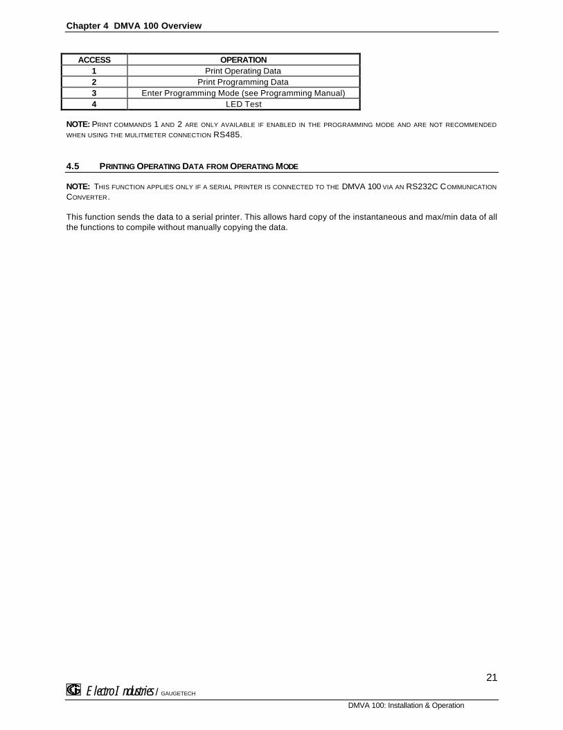
ACCESS MODE
Sections 4.6, 4.7 and 4.8 allow the user to access specific operation tasks (see table below).
Chapter 4 DMVA 100 Overview
Electro Industries / GAUGETECH
DMVA 100: Installation & Operation
21
ACCESS OPERATION1 Print Operating Data2 Print Programming Data3 Enter Programming Mode (see Programming Manual)4 LED Test
NOTE: PRINT COMMANDS 1 AND 2 ARE ONLY AVAILABLE IF ENABLED IN THE PROGRAMMING MODE AND ARE NOT RECOMMENDED
WHEN USING THE MULITMETER CONNECTION RS485.
4.5 PRINTING OPERATING DATA FROM OPERATING MODE
NOTE: THIS FUNCTION APPLIES ONLY IF A SERIAL PRINTER IS CONNECTED TO THE DMVA 100 VIA AN RS232C COMMUNICATION
CONVERTER.
This function sends the data to a serial printer. This allows hard copy of the instantaneous and max/min data of allthe functions to compile without manually copying the data.

Chapter 4 DMVA 100 Overview
Electro Industries / GAUGETECH
DMVA 100: Installation & Operation
22
ðð To PRINT THE OPERATING DATA, follow these steps:
E l e c t r o I n d u s t r i e sE l e c t r o I n d u s t r i e s
MAX/MIN
LIMITS
AC VOLTS
NCBA
AC AMPS
MAX MIN LM2LM1
AN
BN
CN
AB
BC
CA
VOLTSPRINT
AMPSPHASENEXTPROG
E l e c t r o I n d u s t r i e sE l e c t r o I n d u s t r i e s
MAX/MIN
LIMITS
AC VOLTS
NCBA
AC AMPS
MAX MIN LM2LM1
AN
BN
CN
AB
BC
CA
VOLTSPRINT
AMPSPHASENEXTPROG
E l e c t r o I n d u s t r i e sE l e c t r o I n d u s t r i e s
MAX/MIN
LIMITS
AC VOLTS
NCBA
AC AMPS
MAX MIN LM2LM1
AN
BN
CN
AB
BC
CA
VOLTSPRINT
AMPSPHASENEXTPROG
Step 1:a. Press PRINT/PROG to begin thespecial printing sequence.
Step 2:a. The display blanks and 1appears.
b. Press PHASE/NEXT to select.
ðð 111 appears confirming asuccessful print command.
4.6 PRINTING PROGRAMMING DATA FROM OPERATING MODE
NOTE: THIS FUNCTION APPLIES ONLY IF A SERIAL PRINTER IS CONNECTED TO THE DMVA 100 VIA AN RS232C COMMUNICATION
CONVERTER.
This function sends the programming data (or the meter setup) to a serial printer for verification and quickreference.
ðð To PRINT THE PROGRAMMING DATA, follow these steps:
E l e c t r o I n d u s t r i e sE l e c t r o I n d u s t r i e s
MAX/MIN
LIMITS
AC VOLTS
NCBA
AC AMPS
MAX MIN LM2LM1
AN
BN
CN
AB
BC
CA
VOLTSPRINT
AMPSPHASENEXTPROG
E l e c t r o I n d u s t r i e sE l e c t r o I n d u s t r i e s
MAX/MIN
LIMITS
AC VOLTS
NCBA
AC AMPS
MAX MIN LM2LM1
AN
BN
CN
AB
BC
CA
VOLTSPRINT AMPS PHASENEXTPROG
E l e c t r o I n d u s t r i e sE l e c t r o I n d u s t r i e s
MAX/MIN
LIMITS
AC VOLTS
NCBA
AC AMPS
MAX MIN LM2LM1
AN
BN
CN
AB
BC
CA
VOLTSPRINT
AMPSPHASENEXTPROG
Step 1:a. Press PRINT/PROG to enter theaccess mode.
Step 2:ðð The display blanks.
a. Press PRINT/PROG until 2appears.
b. Press PHASE/NEXT to select.
ðð 222 appears confirming asuccessful print command.

Chapter 4 DMVA 100 Overview
Electro Industries / GAUGETECH
DMVA 100: Installation & Operation
23
4.7 LED TEST FROM OPERATING MODE
The DMVA100 is equipped with an LED test to check if the LEDs and annunciators are functioning properly.
E l e c t r o I n d u s t r i e sE l e c t r o I n d u s t r i e s
MAX/MIN
LIMITS
AC VOLTS
NCBA
AC AMPS
MAX MIN LM2LM1
AN
BN
CN
AB
BC
CA
VOLTSPRINT
AMPSPHASENEXTPROG
E l e c t r o I n d u s t r i e sE l e c t r o I n d u s t r i e s
MAX/MIN
LIMITS
AC VOLTS
NCBA
AC AMPS
MAX MIN LM2LM1
AN
BN
CN
AB
BC
CA
VOLTSPRINT
AMPSPHASENEXTPROG
E l e c t r o I n d u s t r i e sE l e c t r o I n d u s t r i e s
MAX/MIN
LIMITS
AC VOLTS
NCBA
AC AMPS
MAX MIN LM2LM1
AN
BN
CN
AB
BC
CA
VOLTSPRINT
AMPSPHASENEXTPROG
Step 1:a. Press PRINT/PROG to enter theAccess Mode.
Step 2:ðð The display blanks.
a. Press PRINT/PROG until 4appears.
Step 3:a. Press PHASE/NEXT for the LEDtest.
ððAll segments and annunciatorsglow.
4.8 ACCESSING FIRMWARE VERSION FROM OPERATING MODE
The DMVA100 is equipped with a function to access the firmware version.
E l e c t r o I n d u s t r i e sE l e c t r o I n d u s t r i e s
MAX/MIN
LIMITS
AC VOLTS
NCBA
AC AMPS
MAX MIN LM2LM1
AN
BN
CN
AB
BC
CA
VOLTSPRINT
AMPSPHASENEXTPROG
Step 1:a. Disconnect power to the meter.
b. Press MAX/MIN/LIMITS upon power up.
ððUpper display indicates the version number.

PROGRAMMING YOUR DMVA 100CHAPTER 1GENERAL PROCEDURE OVERVIEW
Electro Industries / GAUGETECH
DMVA 100: Programming
23
1.1 HOW TO USE THIS PORTION OF THE MANUAL
This manual contains programming for basic operation, available options and parameters. Using the Table ofContents or “Quick Reference Guide”, find the programming feature location and read that chapter.
Programming tasks are arranged into nine major GROUPS. Within each GROUP are the specific meterFUNCTIONS. Outlined is the general approach to alter programming mode values.
1. Enter the Programming Mode.2. Select the desired GROUP.3. Select a FUNCTION within the GROUP.4. After the FUNCTION selection, proceed with DATA ENTRY of the new value for the desired parameter.5. Proceed to program another location and/or exit the programming mode.
IMPORTANT: THE FULL EXITING PROCEDURE MUST BE FOLLOWED TO STORE ANY NEW PROGRAMMING.
1.2 SWITCH PACKS
Electro IndustriesElectro Industries
MAX/MIN
LIMITS
AC VOLTS
NCBA
AC AMPS
MAX MIN LM2LM1
AN
BN
CN
AB
BC
CA
VOLTSPRINT
AMPS PHASENEXTPROG
NEWENTRY
GROUPFUNCTION
PACK
GROUPS, Functions, and Switch PACKS:
• GROUPS are the main category.• Functions are sub categories of GROUPS.• Switch PACKS are sub categories of Functions.
THE DIAGRAM BELOW ILLUSTRATES THE ARRANGEMENT OF THE THREE CATEGORIES:
GROUPS FUNCTIONS SWITCH PACKS
NOTE: THESE ARE VERY SIMILAR TO DIP SWITCH CONCEPT.

Chapter 1 General Procedure Overview
Electro Industries / GAUGETECH
DMVA 100: Programming
24
1.3 PROGRAMMING MODE ENTRY
USED FORP ASSWORDE NTRYMAX/MIN
LIMITSVOLTS A M P S PRINT
PROG
P H A S E
NEXT
USED FOR PROGRAMMING
BUTTON FUNCTION DESCRIPTIONMAX/MIN/LIMITS ADVANCE Scrolls groups, functions, and advances to exit point from function and
group level.PRINT/PROG CHANGE
VALUEScrolls packs, digit counters, and changes Switch PACK position UP orDOWN.
VOLTS STORE Activates new data entry, stores digits, and enters or exits from group orfunction level.
1.4 STANDARD NUMERIC DATA ENTRY
Programmable FUNCTION values are always three digit numeric fields designed to accept any valuebetween 000 and 1999. When entering the value of a function enter all three digits, leading zero's included.For instance, to enter 25, enter: 025.
When activating the Data Entry Sequence, certain Functions allow for a four digit entry. The displayindicates a blank followed by three dashes (see diagram). The first digit may only be a 1 or a blank (theblank signifying 0). Press PRINT/PROG ONCE for 0, TWICE for 1.

CHAPTER 2ENTERING THE PROGRAMMING MODE
25
Electro Industries / GAUGETECH
DMVA 100: Programming
2.1 CHECKSUM ERROR - PROTECTIVE MECHANISM
If the control power is interrupted while in Programming Mode or the user does not fully exit, the meter enters achecksum mode. The display blanks, except for the max LED. Press PRINT/PROG for several seconds and theunit recovers. Follow the procedure to enter the Programming Mode to check program data, then exit.
2.2 PASSWORD ENTRY
The DMVA 100 is password protected. To enter the programming mode, key in the following password. Thepassword is 555.
NOTE: THE METER WILL NOT STORE ANY PROGRAMMING UNLESS PROPERLY EXITED . (SEE CHAPTER 8 TO EXIT).
ððENTERING THE PROGRAMMING MODE:
Electro IndustriesElectro Industries
AC VOLTS
NCBAAC AMPS
MAX MIN LM2LM1
AN
BN
CN
AB
BC
CA
VOLTSPRINTPROG
MAX/MIN
LIMITS AMPS PHASENEXT
Electro IndustriesElectro Industries
AC VOLTS
NCBA
AC AMPS
MAX MIN LM2LM1
AN
BN
CN
AB
BC
CA
VOLTSPRINTPROG
MAX/MIN
LIMITS AMPS PHASENEXT
Electro IndustriesElectro Industries
AC VOLTS
NCBA
AC AMPS
MAX MIN LM2LM1
AN
BN
CN
AB
BC
CA
VOLTSPRINTPROG
MAX/MINLIMITS AMPS PHASE
NEXT
Step 1:a. Press PRINT/PROG until 3appears in lower display.
b. Press PHASE/NEXT to select.
c. 333 appears in lower display.
Step 2:ððDigits begin scrolling in upperdisplay.
⌦⌦The password is 555.
a. Press PHASE/NEXT each time 5appears.
ðð The selected digits appear inlower display.
ððDisplay blanks and PPP flashesin upper display, confirming acorrectly entered password.
ððPPP is replaced by 0. and themeter is now in the ProgrammingMode, GROUP 0.

CHAPTER 3PROGRAMMING GROUP 0: GLOBAL METER SETUP
26
Electro Industries / GAUGETECH
DMVA 100: Programming
The Global Meter Setup includes Functions 0 through 5 that control configuration and basic operation. Below is anoutline of GROUP 0 to assist in locating a feature. FUNCTION 3 System Configuration contains Switch PACKSwith various options, including open delta installation and communications.
TABLE 3-1: GROUP 0 PROGRAMMING FORMAT
FUNCTION NUMBER FUNCTION0. Integration Interval1. Meter Address for Communication2. Baud Rate for Communication3. System Configuration4. Relay 1 Set-up/Time Delay5. Relay 2 Set-up/Time DelayE. Exit Programming GROUP 0
3.1 GROUP 0, FUNCTION 0 - THE INTEGRATION INTERVAL
INTEGRATION INTERVAL: The time over which all instantaneous readings are averaged to obtain a maximum andminimum demand. The Integration Interval is entered in seconds. When entering 15 minutes, enter: 0900seconds.
ðð To change the INTEGRATION INTERVAL, follow these steps:NOTE: PRESS MAX/MIN/LIMITS, AT ANY TIME, TO CANCEL BEFORE STORING THE LAST DIGIT OR SWITCH.
Electro IndustriesElectro Industries
AC VOLTS
NCBA
AC AMPS
MAX MIN LM2LM1
AN
BN
CN
AB
BC
CA
PHASEVOLTSPRINTPROG
MAX/MINLIMITS
AMPS NEXT
Electro IndustriesElectro Industries
AC VOLTS
NCBA
AC AMPS
MAX MIN LM2LM1
AN
BN
CN
AB
BC
CA
PHASEVOLTSPRINTPROGLIMITS NEXT
MAX/MINAMPS
Step 1:a. Enter Group Level of Programming Mode,(see Chp. 2).
b. Press MAX/MIN/LIMITS until 0. appears in upperdisplay.
c. Press VOLTS to activate the GROUP.
ðð 00. appears in upper display, indicating currentGroup and Function number.
ðð Lower display indicates current Interval setting.
Electro IndustriesElectro Industries
AC VOLTS
NCBA
AC AMPS
MAX MIN LM2LM1
AN
BN
CN
AB
BC
CA
PHASEVOLTSPRINTPROG
MAX/MIN
LIMITSAMPS NEXT
Electro IndustriesElectro Industries
AC VOLTS
NCBA
AC AMPS
MAX MIN LM2LM1
AN
BN
CN
AB
BC
CA
PHASEVOLTSPRINTPROG
MAX/MIN
LIMITSAMPS NEXT

Chapter 3 Global Meter Setup
27
Electro Industries / GAUGETECH
DMVA 100: Programming
Step 2:a. Press VOLTS to begin Data Entry Sequence.
ðð Three dashes appear in lower display.
b. Press PRINT/PROG for desired number.Press PRINT/PROG once and the blank signifies zero.Press PRINT/PROG twice and 1 appears.
c. Press VOLTS to store.
ððRepeat this procedure until new Integration Interval isentered.
ððWhen complete, lower display indicates newIntegration Interval.
See Chapter 8 to Exit.
3.2 GROUP 0, FUNCTION 1 - THE METER ADDRESS
METER ADDRESS: Identifies the meter when communicating with a computer system or an RS485 bus. Whennumerous meters are at one site, it is essential that each meter have its own address.
ðð To change the METER ADDRESS, follow these steps:
NOTE: PRESS MAX/MIN/LIMITS, AT ANY TIME, TO CANCEL BEFORE STORING THE LAST DIGIT OR SWITCH.
Electro IndustriesElectro Industries
AC VOLTS
NCBAAC AMPS
MAX MIN LM2LM1
AN
BN
CN
AB
BC
CA
PHASEVOLTSPRINTPROG
MAX/MIN
LIMITSAMPS
NEXT
Electro IndustriesElectro Industries
AC VOLTS
NCBAAC AMPS
MAX MIN LM2LM1
AN
BN
CN
AB
BC
CA
PHASEVOLTSPRINTPROG
MAX/MIN
LIMITSAMPS
NEXT
Step 1:a. Enter Group Level of Programming Mode,(see Chp. 2).
b. Press MAX/MIN/LIMITS until 0. appears in upperdisplay.
c. Press VOLTS to activate the GROUP.
ðð 01. appears in upper display.
ðð Lower display indicates the current Meter Address.
Electro IndustriesElectro Industries
AC VOLTS
NCBAAC AMPS
MAX MIN LM2LM1
AN
BN
CN
AB
BC
CA
PHASEVOLTSPRINTPROG
MAX/MIN
LIMITSAMPS
NEXT
Electro IndustriesElectro Industries
AC VOLTS
NCBAAC AMPS
MAX MIN LM2LM1
AN
BN
CN
AB
BC
CA
PHASEVOLTSPRINTPROG
MAX/MIN
LIMITSAMPS
NEXT
Step 2:a. Press VOLTS to activate Data Entry Sequence.
ðð Three dashes appear in lower display.
b. Press PRINT/PROG fordesired number.• Press PRINT/PROG once and the blank signifies a
zero.• Press PRINT/PROG twice and 1 appears.
c. Press VOLTS to store.
ððRepeat this procedure until new Address is entered.
ððWhen complete, lower display indicates newAddress.
See Chapter 8 to Exit.

Chapter 3 Global Meter Setup
28
Electro Industries / GAUGETECH
DMVA 100: Programming
3.3 GROUP 0, FUNCTION 2 - COMMUNICATION BAUD RATE
BAUD RATE: Speed at which data is transmitted between device and remote computer. The rate programmed intothe meter must match the rate used by the remote polling device.
Valid Baud Rates are 1200, 2400, and 4800. When entering a baud rate, the last zero is omitted. Therefore, threedigits and a leading zero (or blank) must be entered. Example: to enter a baud rate of 2400, enter 0240.
ðð To change the COMMUNICATION BAUD RATE, follow these steps:
NOTE: PRESS MAX/MIN/LIMITS, AT ANY TIME, TO CANCEL BEFORE STORING THE LAST DIGIT OR SWITCH.
Electro IndustriesElectro Industries
AC VOLTS
NCBAAC AMPS
MAX MIN LM2LM1
AN
BN
CN
AB
BC
CA
PHASEVOLTSPRINTPROG
MAX/MIN
LIMITSAMPS
NEXT
Electro IndustriesElectro Industries
AC VOLTS
NCBAAC AMPS
MAX MIN LM2LM1
AN
BN
CN
AB
BC
CA
PHASEVOLTSPRINTPROG
MAX/MIN
LIMITSAMPS
NEXT
Step 1:a. Enter Group Level of Programming Mode(see Chp. 2).
b. Press MAX/MIN/LIMITS until 0. appears in upperdisplay.
c. Press VOLTS to activate the Group.
ðð 02. appears in upper display.
ðð Lower display indicates current Baud Rate.
Electro IndustriesElectro Industries
AC VOLTS
NCBAAC AMPS
MAX MIN LM2LM1
AN
BN
CN
AB
BC
CA
PHASEVOLTSPRINTPROG
MAX/MIN
LIMITSAMPS
NEXT
Electro IndustriesElectro Industries
AC VOLTS
NCBAAC AMPS
MAX MIN LM2LM1
AN
BN
CN
AB
BC
CA
PHASEVOLTSPRINTPROG
MAX/MIN
LIMITSAMPS
NEXT
Step 2:a. Press VOLTS to begin Data Entry Sequence.
b. Three dashes appear in lower display.
c. Press VOLTS to select.
ððRepeat this procedure until new CommunicationBaud Rate is entered.
ððWhen complete, lower display indicates new BaudRate.
See Chapter 8 to Exit.
3.4 GROUP 0, FUNCTION 3 - SYSTEM CONFIGURATION
The System Configuration Function is used to set basic meter operational parameters. (This Functionutilizes Switch PACKS).

Chapter 3 Global Meter Setup
29
Electro Industries / GAUGETECH
DMVA 100: Programming
FUNCTION 3 contains six Switch PACKS, 0 - 5. Each PACK contains three individual UP/DOWN (toggle)switches.
• Toggling the segment UP and DOWN, toggles the switch ON and OFF respectively, or choosesbetween two options.
• The meter displays one Switch PACK at a time.

Chapter 3 Global Meter Setup
30
Electro Industries / GAUGETECH
DMVA 100: Programming
ððPress PRINT/PROG to scroll from PACK to PACK.
FUNCTION
PACKGROUP
NEW
ENTRY
A B C
Electro IndustriesElectro Industries
AC VOLTS
NCBA
AC AMPS
MAX MIN LM2LM1
AN
BN
CN
AB
BC
CA
PHASEVOLTSPRINTPROG
MAX/MIN
LIMITSAMPS
NEXT
TABLE 3-2: SWITCH FEATURES
PACK SWITCH FEATURE SEGMENT POSITION0 A Reserved -
B Reserved -C Reserved -
1 A Reserved -B Blank non-significant leading zero(s) UP ð Enable
DOWN ð DisableC Reset Protection
(See User’s Installation & OperationSection)
UP ð EnableDOWN ð Disable
2 A Reserved -B Open Delta Installation UP ð Enable
DOWN ð DisableC Reserved -
3 A Reserved -B Reserved -C Reserved -
4 A Relay Control I UP ð Alarm OnlyDOWN ð Computer Control & Alarm
B Relay Control II UP ð Alarm OnlyDOWN ð Computer Control & Alarm
C-
UP ð Comm.DOWN ð Disable Comm. and Print
5 A-
UP ð PrintDOWN ð Disable Print
NOTE: TO PRINT: PACK 4, SWITCH C MUST BE IN THE UP POSITION.

Chapter 3 Global Meter Setup
31
Electro Industries / GAUGETECH
DMVA 100: Programming

Chapter 3 Global Meter Setup
30
Electro Industries / GAUGETECH
DMVA 100: Programming
3.5 GROUP 0, FUNCTION 3 - PROGRAMMING PROCEDURE
ðð To change the SYSTEM CONFIGURATION SWITCH settings, follow these steps:
NOTE: PRESS MAX/MIN/LIMITS, AT ANY TIME, BEFORE STORING THE LAST DIGIT OR SWITCH.
Electro IndustriesElectro Industries
AC VOLTS
NCBAAC AMPS
MAX MIN LM2LM1
AN
BN
CN
AB
BC
CA
PHASEVOLTSPRINTPROG
MAX/MIN
LIMITSAMPS
NEXT
Electro IndustriesElectro Industries
AC VOLTS
NCBAAC AMPS
MAX MIN LM2LM1
AN
BN
CN
AB
BC
CA
PHASEVOLTSPRINTPROG
MAX/MIN
LIMITSAMPS
NEXT
Step 1:a. Enter Group Level of Programming Mode,(see Chp. 2).
b. Press MAX/MIN/ LIMITS until 0. appears in upperdisplay.
c. Press VOLTS to activate the Group.
ðð 03.0 appears in upper display.
ðð Lower display indicates current PACK 0 SwitchSettings.
Electro IndustriesElectro Industries
AC VOLTS
NCBAAC AMPS
MAX MIN LM2LM1
AN
BN
CN
AB
BC
CA
PHASEVOLTSPRINTPROG
MAX/MIN
LIMITSAMPS
NEXT
Electro IndustriesElectro Industries
AC VOLTS
NCBAAC AMPS
MAX MIN LM2LM1
AN
BN
CN
AB
BC
CA
PHASEVOLTSPRINTPROG
MAX/MIN
LIMITSAMPS
NEXT
Step 2:a. Press PRINT/PROG until desired PACK appears.
b. Press VOLTS to begin Data Entry Sequence.
ðð Three dashes appear in lower display.
Step 3:a. Press PRINT/PROG to toggle the segments UP orDOWN for desired setting.
b. Press VOLTS to store
See Chapter 8 to Exit.
3.6 GROUP 0, FUNCTIONS 4-5 - TIME DELAY FOR RELAYS 1 & 2 (OPTION NL)
The DMVA 100 can be equipped with a relay option. Two relays are included in this option. The relays can be usedin computer controlled or dedicated alarm options.
COMPUTERCONTROLLED
The relays can be locked or unlocked through a computer (must have communicationoption).
DEDICATED ALARM The relays can be locked or unlocked using the meter's keypad or its measured inputs.The computer cannot change the state of the relay.

Chapter 3 Global Meter Setup
31
Electro Industries / GAUGETECH
DMVA 100: Programming
Under GROUP 0, FUNCTIONS 4-5, time delay for the Relays 1 or 2 can be set between 0 - 255 seconds. Thisallows conditions to exist for a specified time period before the relay or alarm activates. If a time greater than 255seconds is entered, the meter defaults to the maximum value of 255 seconds.EXAMPLE 1:
Relay 1 will be “SET” once the reading exceeds 5.00 amps. Relay 1 will be “RESET” once the reading fallsbelow 5.00 amps.
5 . 0 0 A
0 A
R E S E T
L 1
S E T
N O P O W E R T O T H E U N I T R E S E T
1. Enter in GROUP 0, FUNCTION 4, Segment C and D: UP, DOWN2. Enter in GROUP 4, FUNCTION 2, LIMIT 1, Segments B, C, and D: UP, UP, DOWN
EXAMPLE 2: NORMALLY RESET - NON-EVENT CONDITION WILL RESET RELAY
Relay 1 will be “SET” if the instantaneous reading for amps is below 4.00 amps or above 5.00 amps. Underall other conditions the relay will be “RESET”.
NOTE: UNDER THIS SETUP THE RELAY WILL NOT ACT AS A PROTECTIVE SWITCH.
4 . 0 0 A
5 . 0 0 A
0 . 0 0 A S E T
S E T
L M 2
L M 1
R E S E T
N O P O W E R T O T H E U N I T R E S E T
PROGRAMMING STEPS:1. Enter in GROUP 0, FUNCTION 4, Segments C and D: UP, UP2. Enter in GROUP 4, FUNCTION 2, LIMIT 1, Segments: B, C, and D: UP, UP, DOWN. Value: 5.003. Enter in GROUP 4, FUNCTION 2, LIMIT 2, Segments: DOWN, UP, DOWN. Value: 4.00

Chapter 3 Global Meter Setup
32
Electro Industries / GAUGETECH
DMVA 100: Programming
ðð To change the TIME DELAY FOR RELAY 1 OR RELAY 2, follow these steps:
PRESS MAX/MIN/LIMITS, AT ANY TIME, TO CANCEL BEFORE STORING THE LAST DIGIT OR SWITCH.
Electro IndustriesElectro Industries
AC VOLTS
NCBAAC AMPS
MAX MIN LM2LM1
AN
BN
CN
AB
BC
CA
PHASEVOLTSPRINTPROG
MAX/MIN
LIMITSAMPS
NEXT
Electro IndustriesElectro Industries
AC VOLTS
NCBAAC AMPS
MAX MIN LM2LM1
AN
BN
CN
AB
BC
CA
PHASEVOLTSPRINTPROG
MAX/MIN
LIMITSAMPS
NEXT
Step 1:a. Enter Group Level of Programming Mode(see Chp. 2).
b. Press MAX/MIN/LIMITS until 0. appears.
c. Press VOLTS to activate the Group.
Step 2:To program Relay 1:a. Press MAX/MIN/LIMITS until 04. appears in upperdisplay.
To program Relay 2:a. Press MAX/MIN/LIMITS until 05. appears in upperdisplay.
ðð Lower display indicates current Time Delays.
Electro IndustriesElectro Industries
AC VOLTS
NCBAAC AMPS
MAX MIN LM2LM1
AN
BN
CN
AB
BC
CA
PHASEVOLTSPRINTPROG
MAX/MIN
LIMITSAMPS NEXT
Electro IndustriesElectro Industries
AC VOLTS
NCBAAC AMPS
MAX MIN LM2LM1
AN
BN
CN
AB
BC
CA
PHASEVOLTSPRINTPROG
MAX/MIN
LIMITSAMPS
NEXT
Step 3:a. Press VOLTS and two dashes appear in lowerdisplay.
b. Press MAX/MIN/LIMITS and three dashes appear inlower display.
c. Press PRINT/PROG for desired number.• Press PRINT/PROG once and the blank signifies a
zero.• Press PRINT/PROG twice and 1 appears.
d. Press VOLTS to store.
ððRepeat this procedure until desired value is entered.
ðð Lower display indicates the current Time Delay.
See Chapter 8 to Exit.

CHAPTER 4PROGRAMMING GROUP 1
33
Electro Industries / GAUGETECH
DMVA 100: Programming
4.1 SCALE SELECTIONS AND FULL SCALE SETTINGS
Programming GROUP 1 functions provide a selection of Full Scale Settings to accommodate the different CTs andPTs. The decimal point may be positioned for maximum resolution. The user can perform Scale Selection in eachfunction. The site technician has a choice of Full Scale selection between volts and kilovolts, and amps andkiloamps.
NOTE: DUE TO THE RESOLUTION CAPABILITY , READINGS OVER 2000 COUNTS RESULT IN A LESS STABLE MEASUREMENT.
ðð Tables 4-0 and 4-1 contain Full Scale settings for typical voltages and currents (PT and CT arrangements):
TABLE 4-0INPUT VOLTAGE PT RATIO FULL SCALE
120/208V 1:1 (DIRECT) 120V120/208V 4:1 480V120/208V 12:1 1.44KV
277/480V (SUFFIX G) 1:1 (DIRECT) 300V
TABLE 4-1INPUT CURRENT CT TYPE FULL SCALE
0 - 5A NONE 5.00A0 - 1000A 1000/5 1000A0 - 5000 A 5000/5 5.00KA
TABLE 4-2: GROUP 1 PROGRAMMING FORMAT
FUNCTION NUMBER FUNCTION0. Full Scale Selection for Volts1. Full Scale Selection for AmpsE. Exit Programming GROUP 1
4.2 GROUP 1, FUNCTIONS 0-1: FULL SCALE SETTINGS, VOLT & AMP CHANNELS, VOLT & AMP DECIMAL
PLACEMENT
ðð To change the VOLT OR AMP FULL SCALE settings (Function 0 and 1, respectively), follow these steps:
NOTE: PRESS MAX/MIN/LIMITS, AT ANY TIME, TO CANCEL BEFORE STORING THE LAST DIGIT OR SWITCH.
Electro IndustriesElectro Industries
AC VOLTS
NCBAAC AMPS
MAX MIN LM2LM1
AN
BN
CN
AB
BC
CA
PHASEVOLTSPRINTPROG
MAX/MIN
LIMITSAMPS
NEXT
Electro IndustriesElectro Industries
AC VOLTS
NCBAAC AMPS
MAX MIN LM2LM1
AN
BN
CN
AB
BC
CA
PHASEVOLTSPRINTPROG
MAX/MIN
LIMITSAMPS
NEXT

Chapter 4 Programming GROUP 1
34
Electro Industries / GAUGETECH
DMVA 100: Programming
Step 1:a. Enter Group Level of Programming Mode,(see Chp. 2).
b. Press MAX/MIN/LIMITS until 1. appears in upperdisplay.
c. Press VOLTS to activate the Group.
Step 2:ðð 10. appears in upper display.
ðð Lower display indicates Full Scale setting.
ððA segment appears in upper display.
ððUP signifies - Kilovolts.ððDOWN signifies - Volts.
a. Press VOLTS to begin Data Entry Sequence.
Electro IndustriesElectro Industries
AC VOLTS
NCBA
AC AMPS
MAX MIN LM2LM1
AN
BN
CN
AB
BC
CA
PHASEVOLTSPRINTPROG
MAX/MIN
LIMITSAMPS NEXT
Electro IndustriesElectro Industries
AC VOLTS
NCBA
AC AMPS
MAX MIN LM2LM1
AN
BN
CN
AB
BC
CA
PHASEVOLTSPRINTPROG
MAX/MIN
LIMITSAMPS
NEXT
ENTERING THE FULL SCALE FACTOR
Step 3:ððA dash appears in lower display.
a. Press PRINT/PROG to move the segment UP orDOWN.
b. Press VOLTS to store.
DECIMAL POINT SELECTION
Step 4:a. Press PRINT/PROG to begin decimal placement.
b. Press VOLTS to store
ððNOTE: THE DECIMAL POINT FOR 1999. DOES NOT APPEAR
ON THE DISPLAY .
Electro IndustriesElectro Industries
AC VOLTS
NCBA
AC AMPS
MAX MIN LM2LM1
AN
BN
CN
AB
BC
CA
PHASEVOLTSPRINTPROG
MAX/MIN
LIMITSAMPS NEXT
Electro IndustriesElectro Industries
AC VOLTS
NCBA
AC AMPS
MAX MIN LM2LM1
AN
BN
CN
AB
BC
CA
PHASEVOLTSPRINTPROG
MAX/MIN
LIMITSAMPS NEXT

Chapter 4 Programming GROUP 1
35
Electro Industries / GAUGETECH
DMVA 100: Programming
Step 5 :ðð Three dashes appear in lower display.
a. Press PRINT/PROG for desired number.• Press PRINT/PROG once and the blank signifies a
zero.• Press PRINT/PROG twice and 1 appears.
b. Press VOLTS to store.
ððRepeat this procedure until desired value is entered
ððWhen complete, lower display indicates new FullScale setting.
See Chapter 8 to Exit.

CHAPTER 5PROGRAMMING GROUP 2: METER CALIBRATION
35
Electro Industries / GAUGETECH
DMVA 100: Programming
5.1 STANDARD CALIBRATION
WARNING - READ THIS SECTION CAREFULLY BEFORE PROCEEDING
⌦⌦ Calibration does not need to be accomplished to change CT or PT ratios. (See GROUP 1)
⌦⌦ Meter calibration cannot be performed if the meter is installed for service. The sensing must be connected to a power supply with variable voltage and separate current outputs.
⌦⌦ The calibration procedure requires highly accurate and stable input signals. Incorrect readings result from improper calibration procedures. If unsure, return unit to the factory for calibration.
⌦⌦ BEFORE calibrating any channel, make note of its Full Scale Setting (see Chp. 4). Set the Full Scale in accordance with Table 5-1 for calibration. Restore original Full Scale Setting when calibration is completed.
⌦⌦ The first function in GROUP 2 (STD.CORR) is NOT to be changed by the user. Please make note of the value here (oooooooo ) before using any other function in this Group. If the STD.CORR value is inadvertently lost or changed, contact the factory for assistance.
All sensitive electronic measuring devices drift slightly over time, requiring periodic calibration. We recommendreturning the meter to the factory on a yearly basis.
TABLE 5-0: GROUP 2 PROGRAMMING FORMAT
FUNCTION NUMBER FUNCTIONP. Standard Correction. Factory Procedure only.0. High End Calibration, VOLTS AN1. High End Calibration, VOLTS BN2. High End Calibration, VOLTS CN3. High End Calibration, AMPS A4. High End Calibration, AMPS B5. High End Calibration, AMPS C6. Low End Calibration, AMPS A7. Low End Calibration, AMPS B8. Low End Calibration, AMPS CE. Exit Programming GROUP 2
The Full Scale and Calibration values should be equal during the calibration procedure. The meter may berescaled without calibrating by changing the full scale in GROUP 1, FUNCTION 0 or 1. (See Table 5-1)
TABLE 5-1: SOURCE, FULL SCALE AND VALUE SETTINGS FOR CALIBRATION
CALIBRATION TYPE/RANGES
CALIB. SOURCENECESSARY
FULL SCALE SETTING CALIBRATION VALUE
VOLTS 120/208V 120V 120V 120VOLTS 277/480V 300V 300V 300
VOLTS 4/1 PT 120V 480V 480VOLTS 60/1 PT 120V 7.20KV 7.20
AMPS Hi End 1000/5 CT 5A 1000A 1000AMPS Hi End 5000/5 CT 5A 5.00KA 5.00

Chapter 5 Programming GROUP 2: Meter Calibration
36
Electro Industries / GAUGETECH
DMVA 100: Programming
AMPS Lo End 1000/5 CT 2.5A 500AMPS Lo End 5000/5 CT 2.5A 2.50
5.2 GROUP 2, FUNCTIONS 0-8: HIGH END CALIBRATION OF VOLTAGE CHANNELS, HIGH & LOW END
CALIBRATION OF AMPERAGE CHANNELS
ðð To change the CALIBRATION, follow these steps:
NOTE: PRESS MAX/MIN/LIMITS, AT ANY TIME, TO CANCEL BEFORE STORING THE LAST DIGIT OR SWITCH.
Electro IndustriesElectro Industries
AC VOLTS
NCBAAC AMPS
MAX MIN LM2LM1
AN
BN
CN
AB
BC
CA
PHASEVOLTSPRINTPROG
MAX/MIN
LIMITSAMPS
NEXT
Electro IndustriesElectro Industries
AC VOLTS
NCBAAC AMPS
MAX MIN LM2LM1
AN
BN
CN
AB
BC
CA
PHASEVOLTSPRINTPROG
MAX/MIN
LIMITSAMPS
NEXT
Step 1:a. Enter Group Level of Programming Mode,(see Chp. 2).
b. Press MAX/MIN/LIMITS until 2. appears in upperdisplay.
c. Press VOLTS activate the Group.
ððA one digit password is required to continue.
d. Press PRINT/PROG until 5 appears.
e. Press VOLTS to select.
Step 2:ððRefer to Table 5-0 for Function Number thatcorresponds to channel requiring calibration.
a. Press MAX/MIN/LIMITS (to calibrate VOLTS BN)until 21. appears in upper display.
ðð (2P is pre-calibrated. This is a factory set value andshould not be altered).
Electro IndustriesElectro Industries
AC VOLTS
NCBAAC AMPS
MAX MIN LM2LM1
AN
BN
CN
AB
BC
CA
PHASEVOLTSPRINTPROG
MAX/MIN
LIMITSAMPS
NEXT
Electro IndustriesElectro Industries
AC VOLTS
NCBAAC AMPS
MAX MIN LM2LM1
AN
BN
CN
AB
BC
CA
PHASEVOLTSPRINTPROG
MAX/MIN
LIMITSAMPS
NEXT

Chapter 5 Programming GROUP 2: Meter Calibration
37
Electro Industries / GAUGETECH
DMVA 100: Programming
Step 3:ððApply the calibration to the appropriate channel.
a. Press VOLTS to activate calibration.
b. Press PRINT/PROG for desired number.
Press PRINT/PROG once and the blank signifies azero.
Press PRINT/PROG twice and 1 appears.
c. Press VOLTS to store.
ððWhen complete, lower display indicates thecalibrated reading after 10-15 seconds .
Step 4:a. Press MAX/MIN/LIMITS to exit calibration sequence.
ððProceed to calibrate another function, or exit.
See Chapter 8 to Exit.
¦¦ REPEAT THIS PROCEDURE FOR FUNCTIONS 0 - 5.
¦¦ FOR FUNCTIONS 6-8 , FOLLOW THESE STEPS:
NOTE: PRESS MAX/MIN/LIMITS, AT ANY TIME, TO CANCEL BEFORE STORING THE LAST DIGIT OR SWITCH.
Electro IndustriesElectro Industries
AC VOLTS
NCBAAC AMPS
MAX MIN LM2LM1
AN
BN
CN
AB
BC
CA
PHASEVOLTSPRINTPROG
MAX/MIN
LIMITSAMPS
NEXT
Electro IndustriesElectro Industries
AC VOLTS
NCBAAC AMPS
MAX MIN LM2LM1
AN
BN
CN
AB
BC
CA
PHASEVOLTSPRINTPROG
MAX/MIN
LIMITSAMPS
NEXT
Step 1:a. Enter Group Level of Programming Mode,(see Chp. 2).
b. Press MAX/MIN/LIMITS until 2. appears in upperdisplay.
c. Press VOLTS to activate the Group.
ððA single dash appears indicating a one digitpassword is required to continue.
d. Press PRINT/PROG until 5 appears.
e. Press VOLTS to select.
Step 2:a. Press MAX/MIN/LIMITS until 26. appears in upperdisplay.
b. Press VOLTS to activate.
ðð Lower display blanks.
ððAfter 10 seconds, three dashes appear in lowerdisplay.

Chapter 5 Programming GROUP 2: Meter Calibration
38
Electro Industries / GAUGETECH
DMVA 100: Programming
Electro IndustriesElectro Industries
AC VOLTS
NCBAAC AMPS
MAX MIN LM2LM1
AN
BN
CN
AB
BC
CA
PHASEVOLTSPRINTPROG
MAX/MIN
LIMITSAMPS
NEXT
Electro IndustriesElectro Industries
AC VOLTS
NCBAAC AMPS
MAX MIN LM2LM1
AN
BN
CN
AB
BC
CA
PHASEVOLTSPRINTPROG
MAX/MIN
LIMITSAMPS
NEXT
Step 3: Step 4:a. Press PRINT/PROG for desired number.
b. Press VOLTS to store.
ððWhen complete, lower display indicates thecalibrated reading after 10-15 seconds .
a. Press MAX/MIN/LIMITS at exit calibration sequence.
ððProceed to calibrate another function, or exit.
See Chapter 8 to Exit.

CHAPTER 6PROGRAMMING GROUP 4: SET LIMITS & RELAYS
38
Electro Industries / GAUGETECH
DMVA 100: Programming
GROUP 4 contains LM1 and LM2 set limit values for the voltage and amperage scale allowing the user to programthe limits for the following Groups: VOLTS phase-to-neutral, VOLTS phase-to-phase, AMPS A, B, C, and AMPSneutral.
DIAGRAM 6.1: EXAMPLE OF LM1/LM2 SET LIMITS, VOLTS AND AMPS
LM1 AND LM2 SET LIMITS
PHASES
CURRENT
0
20
40
60
80
100
120
A B C
120
40
LM1 is triggered
LM2 is triggered
50(AMPS)
80
LM1 SET TOTRIGGER ABOVE100 AMPS.
LM2 SET TOTRIGGER BELOW50 AMPS.
6.1 TRIP RELAY
The DMVA 100 has two Relays. These relays are linked through the program to Set Limits LM1 and LM2. The usercan program above or below set limits for every reading. When a measurement exceeds a particular value, the setlimit triggers and alerts the user. Each relay is programmed to a separate delay time (see Chp. 4).
NOTE: EACH LIMIT CAN BE PROGRAMMED TO TRIGGER THE TWO INTERNAL FORM C DRY CONTACT RELAYS FOR ALARM OR
SECONDARY PROTECTION .
GROUP 4: SET LIMITS FOR VOLTS/AMPS
TABLE 6-0: GROUP 4 PROGRAMMING FORMAT
FUNCTION NUMBER FUNCTION0. LM1/LM2 Set Limits for Volts AN,BN,CN1. LM1/LM2 Set Limits for Volts AB,CB,CA2. LM1/LM2 Set Limits for Amps A,B,C3. LM1/LM2 Set Limits for Amps NeutralE. Exit Programming GROUP 4
NOTE: IN TABLE 6-0, ALL FUNCTIONS HAVE A TWO PART ENTRY.
Part 1: The first switch sets the limit to trip either above or below the limit value.The second switch sets whether Relay 1 will trip when the condition occurs.The third switch sets whether Relay 2 will trip when the condition occurs.
Part 2: The second part is the Limit Value.

Chapter 6 Set Limits & Relays
39
Electro Industries / GAUGETECH
DMVA 100: Programming
r GROUP 4, FUNCTIONS 0 - 3: LM1/LM2 SET LIMITS
P R E S S P H A S E / N E X T T O T O G G L EB E T W E E N S E G M E N T A N D L I M I TV A L U E .
L I M I T V A L U EU S E T H E P R I N T / P R O G B U T T O NT O T O G G L E B E T W E E NL M 1 A N D L M 2 .
F R O M L E F T T O R I G H T :S E T L I M I T A B O V E O RB E L O W , T R I P R E L A Y IA N D T R I P R E L A Y I I .
E l e c t r o I n d u s t r i e s
A C V O L T S
NCBA
A C A M P S
M A X M I N L M 2L M 1
A
N
B
N
C
N
A
B
B
C
C
A
V O L T SP R I N T
P R O G
M A X / M I N
L I M I T SA M P S
P H A S E
N E X T
E l e c t r o I n d u s t r i e s
A C V O L T S
NCBA
A C A M P S
M A X M I N L M 2L M 1
A
N
B
N
C
N
A
B
B
C
C
A
V O L T SP R I N T
P R O G
M A X / M I N
L I M I T SA M P S
P H A S E
N E X T
EXAMPLE: FUNCTION 0LM1 LED LM2 LED ABOVE/BELOW RELAY 1 RELAY 2 VALUE
ON OFF Digit Up Digit Up Digit Down 120OFF ON Digit Down Digit Down Digit Up 090
TABLE 6-1: FUNCTION 0LM1 LED LM2 LED ABOVE/ BELOW RELAY 1 RELAY 2 LEVEL
ON OFF Digit Up-trigger above levelDigit Down- trigger below
level
Digit Up - enabledDigit Down-disabled
Digit Up- enabledDigit Down-
disabled
0-1999
OFF ON Digit Up-trigger above levelDigit Down-trigger below level
Digit Up- enabledDigit Down-disabled
Digit Up-enabledDigit Down-disabled
0-1999
NOTE: IF VOLTAGES EXCEED 120V, LM1 IS TRIGGERED AND RELAY 1 IS ENABLED . IF VOLTAGES DO NOT EXCEED 90V, LM2 ISTRIGGERED AND RELAY 2 IS ENABLED .

Chapter 6 Set Limits and Relays
40
Electro Industries / GAUGETECH
DMVA 100: Programming
ðð To program LIMITS OR RELAYS, follow these steps:
NOTE: PRESS MAX/MIN/LIMITS, AT ANY TIME, BEFORE STORING THE LAST DIGIT OR SWITCH.
Electro IndustriesElectro Industries
AC VOLTS
NCBAAC AMPS
MAX MIN LM2LM1
AN
BN
CN
AB
BC
CA
PHASEVOLTSPRINTPROG
MAX/MIN
LIMITSAMPS
NEXT
Electro IndustriesElectro Industries
AC VOLTS
NCBAAC AMPS
MAX MIN LM2LM1
AN
BN
CN
AB
BC
CA
PHASEVOLTSPRINTPROG
MAX/MIN
LIMITSAMPS
NEXT
Step 1:a. Enter Group Level of Programming Mode,(see Chp. 2).
b. Press MAX/MIN/LIMITS until 4. appears in upperdisplay.
c. Press VOLTS to activate the Group.
Step 2:a. Press MAX/MIN/LIMITS to select desired Function(0-3).
ðð Lower display provides the currently selected valuefor whether to trip above or below on Relay 1 and Relay2.
LEFT SWITCH: UP position indicates above trippingvalue for lower display’s value. DOWN positionindicates below tripping value for lower display’s value.
MIDDLE SWITCH: UP position sets Relay 1 to trip.DOWN position doesn’t activate Relay 1 when limitcondition exists.
RIGHT SWITCH: Same as Middle Switch, regardingRelay 2.
b. Press PRINT/PROG to toggle between LM1 and LM2setting.
ðð The LM1 or LM2 annunciator indicates the limit beingdisplayed.
Electro IndustriesElectro Industries
AC VOLTS
NCBAAC AMPS
MAX MIN LM2LM1
AN
BN
CN
AB
BC
CA
PHASEVOLTSPRINTPROG
MAX/MIN
LIMITSAMPS
NEXT
Electro IndustriesElectro Industries
AC VOLTS
NCBAAC AMPS
MAX MIN LM2LM1
AN
BN
CN
AB
BC
CA
PHASEVOLTSPRINTPROG
MAX/MIN
LIMITSAMPS
NEXT
Step 3:a. Press VOLTS once.
ðð Lower display is replaced with three dashes.
FOLLOW THIS STEP FOR DISABLING THE LIMIT:a. Press VOLTS (wait 3-6 seconds) to Disable theLimit.
ðð The Set Above/ Below will be set to below.ðð Trip Relay 1 will be disabled.ðð Trip Relay 2 will be disabled.ðð The Level of the Limit will be set to 000.

Chapter 6 Set Limits & Relays
41
Electro Industries / GAUGETECH
DMVA 100: Programming
Electro IndustriesElectro Industries
AC VOLTS
NCBA
AC AMPS
MAX MIN LM2LM1
AN
BN
CN
AB
BC
CA
PHASEVOLTSPRINTPROG
MAX/MIN
LIMITSAMPS NEXT
Electro IndustriesElectro Industries
AC VOLTS
NCBA
AC AMPS
MAX MIN LM2LM1
AN
BN
CN
AB
BC
CA
PHASEVOLTSPRINTPROG
MAX/MIN
LIMITSAMPS NEXT
Step 4:a. Press PRINT/PROG to toggle between LM1 and LM2settings.
b. Press VOLTS to store.
c. Press PRINT/PROG to change current SetAbove/Below, Trip Relay 1, and Trip Relay 2 settings.
ðð This toggles the segments UP (above limit) or DOWN(below limit).
d. Press VOLTS to store.
e. Press MAX/MIN/LIMITS to enter the limit value.
Step 5:a. Press PRINT/PROG to scroll through the digits.• Press PRINT/PROG once and the blank signifies a
zero.• Press PRINT/PROG twice and 1 appears.
b. Press VOLTS to store.
ððUpon completion, the lower display indicates the newsetting.
c. Press PHASE/NEXT to check programmed data.
d. Press PRINT/PROG TO PROGRAM ANOTHERFUNCTION (refer to Step 2).
See Chapter 8 to Exit.

CHAPTER 7PROGRAMMING GROUP 7: PHASE REVERSAL & PHASE IMBALANCE SET
LIMITS/RELAYS
42
Electro Industries / GAUGETECH
DMVA 100: Programming
7.1 VOLTAGE PHASE REVERSAL AND PHASE IMBALANCE
The set limit alerts the user of an unbalanced or a reversed phase in a Three-phase System. The DMVA 100 hastwo options for this purpose.
PHASE REVERSAL:Activates when a reversed phase enters the DMVA 100s metering system.
PERCENT PHASE IMBALANCE:Activates when the user’s present value percent phase imbalance is exceeded. For example: an unbalancedThree-phase System.
DIAGRAM 7.1: EXAMPLE OF SET LIMITS
10:00 AM 11:00 AM
Limits NotTriggered
Limits Triggered
PHASEIMBALANCE
(%)
10.0%
THREE PHASE SYSTEM IMBALANCE
7.2 TRIP RELAY
NOTE: THE -NL OPTION MUST BE PURCHASED TO HAVE RELAYS TRIGGERED FROM LIMIT CONDITIONS.
The DMVA 100 has two Relays. These relays are linked through the program to Set Limits LM1 and LM2. The usercan program above or below set limits for every reading. When a measurement exceeds a particular value, the setlimit triggers and alerts the user. Each relay has provisions for a separate delay time (see Chp. 4).
�� TRIP RELAY I Whether to trip Relay 1.
�� TRIP RELAY II Whether to trip Relay 2.�� LEVEL The level at which the warning mechanism trips. Percentage of voltage imbalance is
entered for setup level.-OR-
�� ENABLE/DISABLE In the event of Phase Reversal, indicates whether to enable or disable phase reversaldetection.
TABLE 7-0: GROUP 7 PROGRAMMING FORMAT
FUNCTION NUMBER FUNCTION0. Voltage Phase Reversal Detection

Chapter 7 Phase Reversal & Phase Imbalance Set Limits/Relays
43
Electro Industries / GAUGETECH
DMVA 100: Programming
1. Voltage Phase ImbalanceE. Exit Programming GROUP 7
7.3 GROUP 7, FUNCTION 0: VOLTAGE PHASE REVERSAL DETECTION
ðð To change the PHASE REVERSAL settings, follow these steps:
NOTE: PRESS MAX/MIN/LIMITS, AT ANY TIME, TO CANCEL BEFORE STORING THE LAST DIGIT OR SWITCH.
Electro IndustriesElectro Industries
AC VOLTS
NCBAAC AMPS
MAX MIN LM2LM1
AN
BN
CN
AB
BC
CA
PHASEVOLTSPRINTPROG
MAX/MIN
LIMITSAMPS
NEXT
Electro IndustriesElectro Industries
AC VOLTS
NCBAAC AMPS
MAX MIN LM2LM1
AN
BN
CN
AB
BC
CA
PHASEVOLTSPRINTPROG
MAX/MIN
LIMITSAMPS
NEXT
Step 1:a. Enter Group Level of Programming Mode.(see Chp. 2)
b. Press MAX/MIN/LIMITS until 7. appears in upperdisplay.
c. Press VOLTS to activate the Group.
ðð 70. appears in upper display.
ðð Lower display indicates current settings forEnable/Disable Phase Reversal Detection.
Electro IndustriesElectro Industries
AC VOLTS
NCBAAC AMPS
MAX MIN LM2LM1
AN
BN
CN
AB
BC
CA
PHASEVOLTSPRINTPROG
MAX/MIN
LIMITSAMPS NEXT
Step 2:a. Press VOLTS once.
ðð Three dashes appear in lower display.
b. Press PRINT/PROG to change current SetAbove/Below, Trip Relay 1, and Trip Relay 2 settings.
ðð This toggles the segments UP (above limit) or DOWN(below limit).
c. Press VOLTS to store.

Chapter 7 Phase Reversal & Phase Imbalance Set Limits/Relays
44
Electro Industries / GAUGETECH
DMVA 100: Programming
7.4 GROUP 7, FUNCTION 1: PERCENTAGE VOLTAGE PHASE IMBALANCE
ðð To change PERCENTAGE VOLTAGE PHASE IMBALANCE, follow these steps:
NOTE: PRESS MAX/MIN/LIMITS, AT ANY TIME, TO CANCEL BEFORE STORING THE LAST DIGIT OR SWITCH.
Electro IndustriesElectro Industries
AC VOLTS
NCBA
AC AMPS
MAX MIN LM2LM1
AN
BN
CN
AB
BC
CA
PHASEVOLTSPRINTPROG
MAX/MIN
LIMITSAMPS
NEXT
Electro IndustriesElectro Industries
AC VOLTS
NCBA
AC AMPS
MAX MIN LM2LM1
AN
BN
CN
AB
BC
CA
PHASEVOLTSPRINTPROG
MAX/MIN
LIMITSAMPS
NEXT
Step 1:a. Enter Group Level of Programming Mode,(see Chp. 2)
b. Press MAX/MIN/LIMITS until 7. appears in upperdisplay.
c. Press VOLTS to activate the Group.
a. Press MAX/MIN/LIMITS until 71. appears in upperdisplay.
ðð Lower display indicates the current PercentageVoltage Phase Imbalance.
Electro IndustriesElectro Industries
AC VOLTS
NCBA
AC AMPS
MAX MIN LM2LM1
AN
BN
CN
AB
BC
CA
PHASEVOLTSPRINTPROG
MAX/MINLIMITS
AMPSNEXT
Electro IndustriesElectro Industries
AC VOLTS
NCBA
AC AMPS
MAX MIN LM2LM1
AN
BN
CN
AB
BC
CA
PHASEVOLTSPRINTPROG
MAX/MINLIMITS
AMPSNEXT
Step 3:a. Press VOLTS once.
b. Press PRINT/PROG to change current SetAbove/Below, Trip Relay 1, and Trip Relay 2 settings.
ðð This toggles the segments UP (above limit) or DOWN(below limit).
c. Press VOLTS to store.
Step 4:a. Press VOLTS to activate the Percentage VoltagePhase Imbalance.
b. Press PRINT/PROG to scroll through the digits.• Press PRINT/PROG once and the blank signifies a
zero.• Press PRINT/PROG twice and 1 appears.
c. Press VOLTS to store.
NOTE: PRESS PHASE/NEXT TO TOGGLE BETWEEN NUMBERSAND SEGMENTS. IF A NUMBER GREATER THAN 5 IS ENTERED ,THE METER DEFAULTS TO 5.
Electro IndustriesElectro Industries
AC VOLTS
NCBA
AC AMPS
MAX MIN LM2LM1
AN
BN
CN
AB
BC
CA
PHASEVOLTSPRINTPROG
MAX/MIN
LIMITSAMPS NEXT
ðð Lower display indicates the new setting.
See Chapter 8 to Exit.

Chapter 7 Phase Reversal & Phase Imbalance Set Limits/Relays
45
Electro Industries / GAUGETECH
DMVA 100: Programming

CHAPTER 8EXITING THE PROGRAMMING MODE
45
Electro Industries / GAUGETECH
DMVA 100: Programming
NOTE: STEPS TO EXIT THE PROGRAMMING MODE VARIES AS THE PROGRAMMING STAGE VARY.
Exiting the Programming Mode is ALWAYS necessary to store any new changes and to calculate a newchecksum. Failure to exit results in a checksum error. The display blanks and the max LED intermittently flashes.
IF YOU ARE LOCATED AT: FUNCTION LEVEL - begin at Step 1GROUP LEVEL - begin at Step 2
Electro IndustriesElectro Industries
AC VOLTS
NCBA
AC AMPS
MAX MIN LM2LM1
AN
BN
CN
AB
BC
CA
PHASEVOLTSPRINTPROG
MAX/MIN
LIMITSAMPS
NEXT
Electro IndustriesElectro Industries
AC VOLTS
NCBA
AC AMPS
MAX MIN LM2LM1
AN
BN
CN
AB
BC
CA
PHASEVOLTSPRINTPROG
MAX/MIN
LIMITSAMPS NEXT
Electro IndustriesElectro Industries
AC VOLTS
NCBA
AC AMPS
MAX MIN LM2LM1
AN
BN
CN
AB
BC
CA
PHASEVOLTSPRINTPROG
MAX/MIN
LIMITSAMPS
NEXT
EXITING FROM FUNCTION LEVEL EXITING FROM GROUP LEVEL
Step 1:a. Press MAX/MIN/ LIMITS until theGroup number in upper display isfollowed by E.
ðð The DMVA 100 re-turns toFunction Level.
Step 1a:a. Press VOLTS to exit fromFunction Level to Group Level.
Step 2:a. Press MAX/MIN/ LIMITS until E.appears in upper display.
b. Press VOLTS to exit entirely fromProgramming Mode.
YOU HAVE EXITED THE PROGRAMMING MODE.
AFTER A MOMENT, THE METER RETURNS TO THE OPERATING MODE.