electro hydraulic, systems design and control · 08.03.2017 1 electro hydraulic, systems design and...
TRANSCRIPT

08.03.2017
1
Electro Hydraulic, Systems Design and Control
To earn Professional Development Hours (PDH):
1. Log into the CONEXPO – CON/AGG App2. Go to this session in “Schedule”3. Check-In using the Slider in Session Detail
About me
Dipl.-Ing.
Janette Kothe Bosch Rexroth AGBrgm.-Dr.-Nebel-Str. 297816 Lohr am Main
Industry 4.0 GERMANYSales Technical Support
Phone +49 9352 18 5062 Mobil +49 173 860 1985
[email protected] www.boschrexroth.com
@janettekothe
o Being a hub for the network of IoT applications experts at Bosch Rexroth
o Product Owner for a IoT Consult + Connect Team
08.03.2017
2
Dipl.-Ing.
Michael Liedhegener Bosch Rexroth AGZum Eisengießer 1
Manager 97816 Lohr am Main Simulation, Industrial Application GERMANYSales Technical Support
Phone +49 9352 18 1095 Mobil +49 172 680 9538
[email protected] www.boschrexroth.com
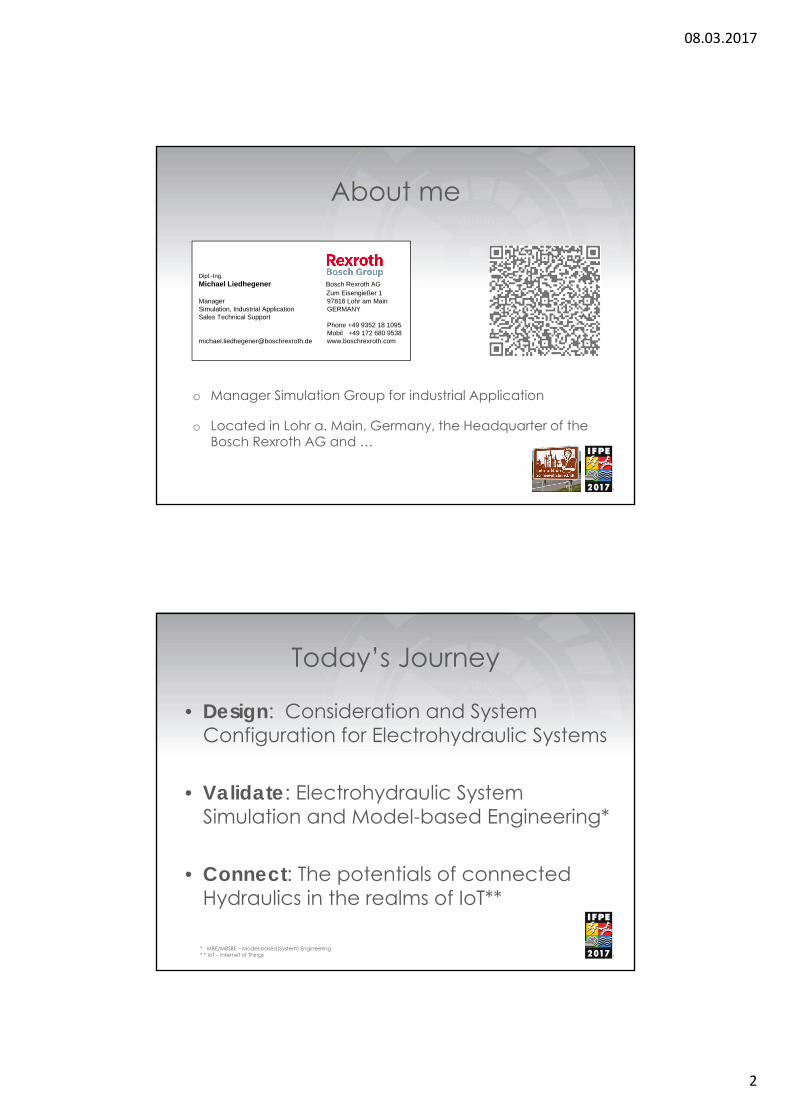
About me
o Manager Simulation Group for industrial Application
o Located in Lohr a. Main, Germany, the Headquarter of the Bosch Rexroth AG and …
Today’s Journey
• Design: Consideration and System Configuration for Electrohydraulic Systems
• Validate: Electrohydraulic System Simulation and Model-based Engineering*
• Connect: The potentials of connected Hydraulics in the realms of IoT**
* MBE/MBSBE – Model-based(System) Engineering* * IoT – Internet of Things
08.03.2017
3
DesignConsiderations and System Configuration
DESIGN
• Proportional Valve and Pump Drives, partners or competing technologies
• Closed hydraulic circuits with VFD* driven pumps challenges and solutions
• Smart HPU’s**, new technologies to make them small, intelligent and cost effective
* VFD – Variable Frequency Drive** HPU – Hydraulic Power Unit

08.03.2017
4
Competing TechnologiesIntroduction
Electrohydraulic hydrostatic drives • “Electro” in the name “electrohydraulic” implies that
most industrial hydraulic drives are driven by an electric motor with hydraulics acting as the “gear” in a hydrostatic transmission
• In addition the hydraulic gear has electrical actuation and feedback (sensors) to enhance the performance and power of the hydraulic drive technology
• With the advent of higher performance and market driven ‘electrical’ VFD’s, Cylinder Direct Drives (CDD) have moved from low dynamic mobile applications to mid to high dynamic industrial applications, a field previously dominated by proportional and servo valve technology.
Electrohydraulic Drive Matrixof hydrostatic drives
Credit Images (I..IV): Prof.Dr.-Ing Backe, Servohydraulik 1992

08.03.2017
5
Competing Technologies
Cylinder Direct Drive (CDD)
Axis VFD
Cylinder Valve Driven (CVD)
HPU Axis
< Cylinder >
< Hydraulic coupling >
< Energy control >
< Energy supply >
hydr
aulic
pow
er u
nit
varia
ble
frequ
ency
driv
e
Physical PropertiesControl Scheme
Cylinder Direct Drive .
• Geometry
• Flow is merely a result of displacement V and shaft speed n
• Pressure ppump is a result of resistance (the load) ‘downstream’
Cylinder Valve Driven
• Bernoulli's Theorem
• Flow Q is a result of pressure differential Δp and throttle area A of the orifice.
• Note: viscosity (temp.) has no impact on Q of an orifice
pyApyQOil
2)(),( voltnVnQ )()(),(
Δp
>
y
Q
Q
>
ϕ
n(t)
ppumppload
psystem
* – coefficient of contraction ~0.7** ρ – density fluid, mineral oil ~0.8 gr/cm3

08.03.2017
6
Physical PropertiesEnergy Consumption
Cylinder Direct Drive • Power required is
essentially only as high as the work done (plus losses)
• Minimum energy (losses) result from flow resistance of hydraulic circuit and component leakage
• In case n = variable also electrical losses of VFD
Cylinder Valve Driven • Power required of valve
drive is commonly as high as the corner horsepower
• At no load condition pSystem
equals Δpvalve (load sensing !)
• Minimum power demand for controllability(app. 30%)
valvevalvecontrol pQP
SystemeMotor pQP max npVP loadeMotor )(21
Physical PropertiesEnergy housekeeping
Cylinder Direct Drive
• Distribution on hydraulic side difficult (direct drive). Sequencing mult. axis by isolating (w/ valves) is possible
• But on electrical side (DC bus) energy distribution is possible
• Regeneration is possible on electric DC bus (e.g. capacitors or kinetic buffering) or pwr. grid
Cylinder Valve Driven
• Energy can easily be distributed (split) on the hydraulic side between multiple axis
• Hydraulic common rail is equivalent to DC bus on electrical side, buffering of psystem reduces corner HP
• Regeneration isn’t possible as braking energy is throttled (metered out) for the sake of controllability

08.03.2017
7
Physical PropertiesEnergy dissipation
Cylinder Direct Drive • No throttle losses to deal
with but braking energy needs to be taken care of– Regen. or brk. resistor (heat)– Cooling effort shifting from
HPU to el. cabinet
• Energy on demand also means noise and heat is generated when operating loaded
– Average noise level is much lower
Cylinder Valve Driven • Heat from meter/throttle
losses need to be removed from HPU and such are paid twice for– 1x as flow meter losses– 1x as cooling effort (30% Pmax)
• Noise handling– HPU can be enclosed– MPG* can be encased– VFD or ‘switch’(PLC code)
can reduce eMotor speed or stopped when idle
* motor pump group
Physical Propertiesdynamics of drive train 1
Cylinder Direct Drive • Pump even though being
connected to both cylinder sides only meters (drives)one side at a time actively.
• The opposite cylinder port is dragged at (low) boost pressure (force ≠ spring)
Cylinder Valve Driven • Prop. valve ‚clamps‘
cylinder between meter in and meter out throttle
• Each metered oil column acts like a spring
08.03.2017
8
Physical Propertiesdynamics of drive train 2
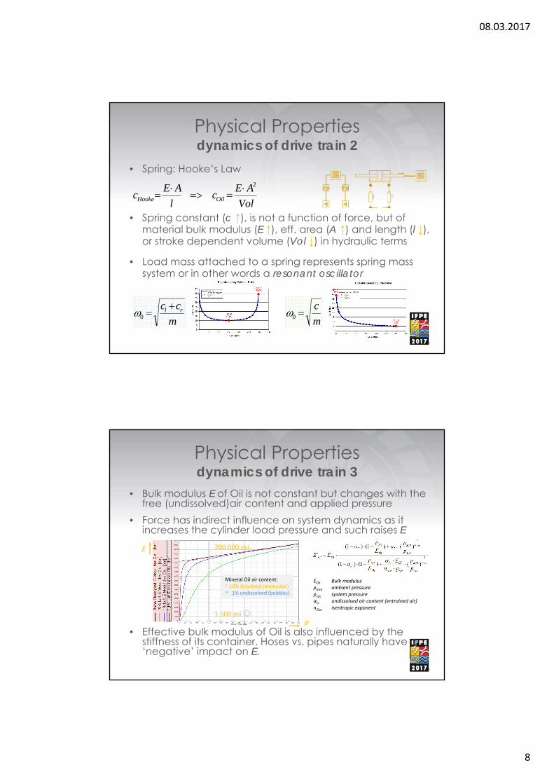
• Spring: Hooke’s Law
• Spring constant (c ↑), is not a function of force, but of material bulk modulus (E ↑), eff. area (A ↑) and length (l ↓), or stroke dependent volume (Vol ↓) in hydraulic terms
• Load mass attached to a spring represents spring mass system or in other words a resonant oscillator
Vol
AEc
l
AEc OilHooke
2
m
cc rl 0 m
c0
Physical Propertiesdynamics of drive train 3
• Bulk modulus E of Oil is not constant but changes with the free (undissolved)air content and applied pressure
• Force has indirect influence on system dynamics as it increases the cylinder load pressure and such raises E
• Effective bulk modulus of Oil is also influenced by the stiffness of its container. Hoses vs. pipes naturally have a ‘negative’ impact on E.
EOil Bulk moduluspatm ambient pressurepsys system pressureαU undissolved air content (entrained air)nGas isentropic exponent
1.500 psi ☺
200.000 psiE
p
Mineral Oil air content:~ 10% dissolved (molecular)~ 1% undissolved (bubbles)

08.03.2017
9
Physical Propertiesdynamics of control
• The whole Motor Pump Group (MPG) with the lumped inertia J limits the max drive train dynamics
• Max VFD current and power limit the max eMotor torque
• Furthermore the external load reduces the available acceleration torque for the MPG
• Prop. valve performs like fast second order system with limited slew rate
• Dynamics are product inherent and independent of external (work) load
• Product datasheet lists valve performance data
• Up to100% system pressure is initially available for cylinder acceleration
Competing Technologiesdifferential cylinders 1
• Create equal area cylinder which looks like diff. cylinder• Add a tube to one side of the cylinder to encase the rod.
This can allow for an integrated position transducer. Drawback is the extra length. Potential issues with buckling, seal side load and footprint in the machine.
• Or build ‘alternative’ equal area cylinder by ‘folding’ or stacking. Additional areas allow for secondary features such as cyl. gear transmission or weight compensation.
• If neither of the above is feasible consider a control option to correct for non-equal cylinder areas ratios

08.03.2017
10
Competing Technologiesdifferential cylinders 2
Cylinder Direct Drive (CDD)• One (symmetrical) pump
can drive the cylinder if anti cavitation / bypass function is in place. But axis velocity is direction dependent for same cmd
• Two pumps matching about the cylinder area ratio equalize the extend / retract axis velocities
Cylinder Valve Driven (CVD)• In case cylinder is approx.
2:1area ratio use a matching 2:1valve spool.
• If C/V ratios diverge, use two 3/3 prop valves one for meter in, one for meter out with ratioed nominal flow
• Note: ratioed spools do balance cylinder chamber pressures not the extend/retract velocity
Competing Technologiesoverall axis features
Cylinder Direct Drive (CDD)• 4 quadrant operation is
possible with suitable pump(s) and boost and flush circuit
• Easy integration in hybrid machine concepts with tankless designs and using the VFD to control axis and technology functions (PFC*)
• Using bus connectivity, can result in IoT enabled designs
Cylinder Valve Driven (CVD)• 4 quadrant operation is
system inherent with 4 active control lands (ratioed to cylinder)
• Smart digital prop. valves can perform as decentralized axis motion controller
• Smart valves with field bus and/or motion controller can report system states for condition monitoring and enable other IoT functions
* position force control
08.03.2017
11
Competing Technologiesmotion control
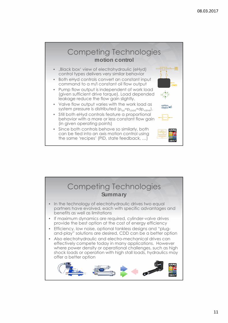
• ‚Black box‘ view of electrohydraulic (eHyd) control types delivers very similar behavior
• Both eHyd controls convert an constant input command to a m/l constant oil flow output
• Pump flow output is independent of work load (given sufficient drive torque). Load depended leakage reduce the flow gain slightly.
• Valve flow output varies with the work load as system pressure is distributed (psys=pLoad+dpvalve).
• Still both eHyd controls feature a proportional behavior with a more or less constant flow gain (in given operating points)
• Since both controls behave so similarly, both can be tied into an axis motion control using the same ‘recipes’ (PID, state feedback, …)
CMD
Competing TechnologiesSummary
• In the technology of electrohydraulic drives two equal partners have evolved, each with specific advantages and benefits as well as limitations
• If maximum dynamics are required, cylinder-valve drives provide the best option at the cost of energy efficiency
• Efficiency, low noise, optional tankless designs and “plug-and-play” solutions are desired, CDD can be a better option
• Also electrohydraulic and electro-mechanical drives can effectively compete today in many applications. However where power density or operational challenges, such as high shock loads or operation with high stall loads, hydraulics may offer a better option

08.03.2017
12
DESIGN
• Proportional Valve and Pump Drives, partners or competing technologies
• Closed hydraulic circuits with VFD driven pumps, challenges and solutions
• Smart HPU’s, new technologies to make them small, intelligent and cost effective
Closed hydraulic circuitsimprove axis dynamics
• The ‘stiffer’ the axis the better its static and dynamic performance. Recap system stiffness:
• Short hoses, pipes and minimizing dead volumes are crucial. A highly integrated tankless axis can fulfill that requirement more easy than discrete designs.
• Increased stiffness through higher bulk modulus can be achieved by raising the inner pressure in the cylinder– boosting the inner pressure by circuit design or motion control (MC)
Vol
AEcOil
2
MC options average pressure control
pcmd = 0.5(pA+ pB) el. counterbalancing
NOT hydraulic!

08.03.2017
13
Closed hydraulic circuitsw/ or w/o fluid reservoirs
• Pump driven circuits impose in general less stress to the medium of power transmission (mineral oil)– No throttle resistance (orifice) with turbulent flow and air dissolvent
from the fluid (stiffness, oil aging, heat, noise)• Tank requirements for closed circuit designs only demand
enough volume to handle oscillating volume plus compression flow and allowance for thermal expansion
• Differential cylinders require the rod volume of fluid as oscillating volume, while equal area cylinders don’t and such are preferred for CDD systems
• Using pressure vessels (accumulators) as reservoirs vs an open tank, eliminates the risk of external contamination
• Oil (pre)filled into a tankless closed system must be pretreated (deaerated, desiccated and filtered)
Closed hydraulic circuitsvalue add of alt. cylinders
• Alternative (custom) cylinders with multiple areas serve the main purpose to keep the oscillating volume to a minimum (for linearity and tankless CDD’s)
• In addition they provide secondary benefits as the multiple areas can be mixed and matched for rapid advance and feed forward speed adjustment (10:1) or weight compensation as in the example below (folded cyl.)
• Rapid advance @ min forceA1 – A3 = A2 (A3 in regen)
V1, V2, V3, V4
effective area A
• Feed speed @ max forceA1 = A3 + A2
• Option weight compensationA4 = 0bar up to pcounterbalance

08.03.2017
14
Closed hydraulic circuitsSelf-contained electro-hydraulic servo axis (SHA)
• Hydraulic Circuit • Assembly Groups
Fast: A1 – A3 = A2Strong: A1 = A3 + A2 See it in action:
Closed hydraulic circuitsCDD in ‘compact’ discrete design
• Hydraulic Circuit • Press system key facts– 2 Mtons of max force– 900kW el Power– 8 MPG’s servo motor driven– Tankless (9 000 Liter saved)
Read the whole article:
1+2974

08.03.2017
15
DESIGN
• Proportional Valve and Pump Drives, partners or competing technologies
• Closed hydraulic circuits with VFD driven pumps, challenges and solutions
• Smart HPU’s, new technologies to make them small, intelligent and cost effective
Smart HPU’srule of thumb
• HPU’s, basically ‘oil barrels’ with a MPG’s attached, can be smart by design if they ‘do more for less’ than state of the art designs can
• Sizing recommendation for the reservoir volume are 3 to 5 time the max pump flow* E.g. a 71cc pump @ 1800 rpm delivers 125 Lpm (33gpm), so reservoir should be 5x125L = 625L (165gal.) or 100/100/63 cm (3/3/2 ft) and it scales from there
• Main reasons for the ‘proven’ sizing rule (of thumb) is the conditioning time needed for (passive) degassing, filtering, cooling, settling of the fluid
* Source: Hydraulic Trainer Volume 3 (ISBN 978-3-9816219-4-5) Page 61, Paragraph 5.1

08.03.2017
16
Smart HPU’sdegassing
• What if with modern technologies in combination with proven design rules, the same requirements (clean, cool, degassed) can be reached at 1x pump flow or even less?
• Degassing for example. Free gas is mainly entering the fluid through fittings, gaskets or other ‘air’ leaks (an oil tight seal is not air tight necessarily) or through the oil surface in the reservoir. And trapped air is escaping from the fluid at the passage through an orifice. Exactly!
Details @ google.com/patents/DE102015216174A1
Smart HPU’sfluid condition
• In general the condition of the hydraulic fluid is affected by mechanical, physical and chemical stress
• Mechanical stress (pressure, flow rate) is connected to the demanded main function of the Machine or Process and therefore not a variable.
• Physical/chemical stress on the hydraulic fluid are typically temperature, air, water and contamination
• Adjustment of physical and chemical stress lead to improved behavior of the application and to increased endurance and lifetime
08.03.2017
17
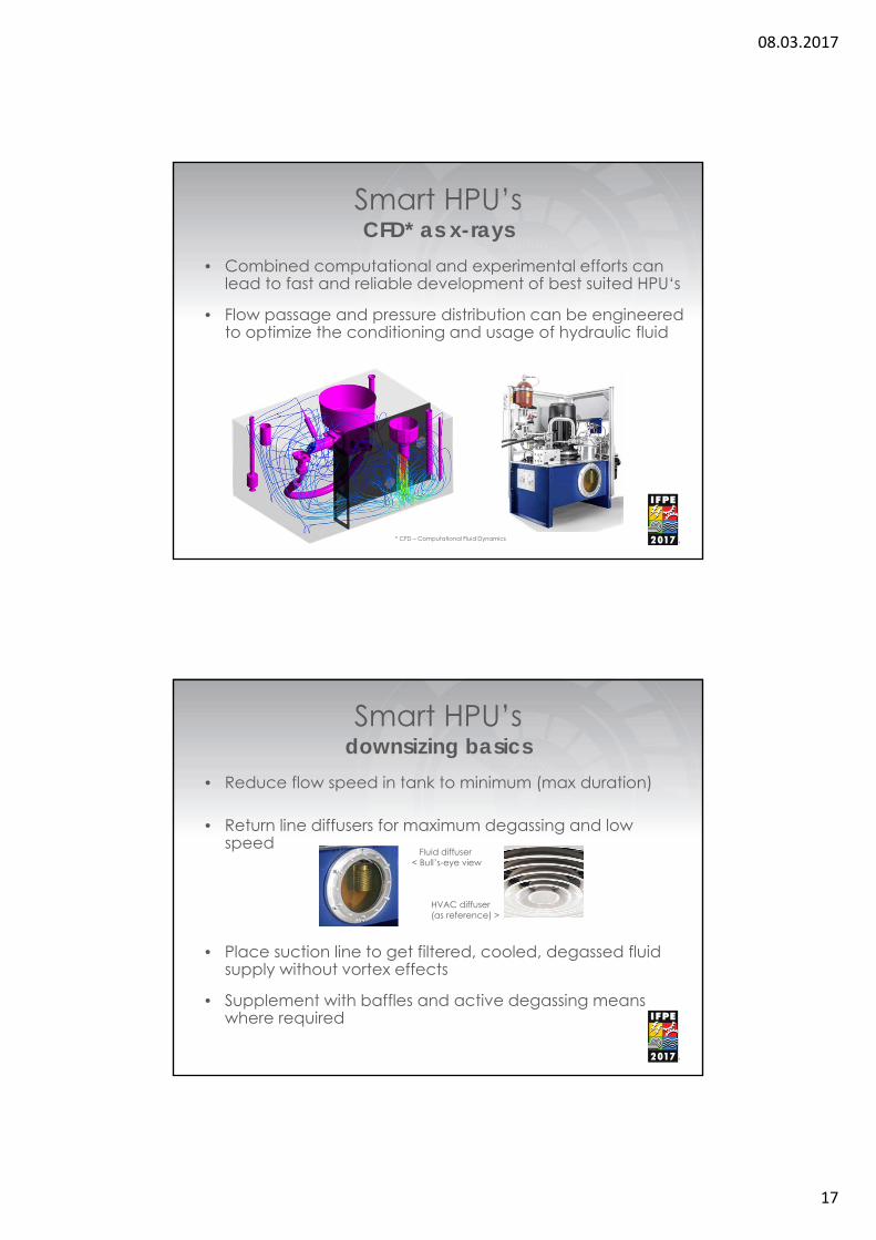
Smart HPU’sCFD* as x-rays
• Combined computational and experimental efforts can lead to fast and reliable development of best suited HPU‘s
• Flow passage and pressure distribution can be engineered to optimize the conditioning and usage of hydraulic fluid
* CFD – Computational Fluid Dynamics
Smart HPU’sdownsizing basics
• Reduce flow speed in tank to minimum (max duration)
• Return line diffusers for maximum degassing and low speed
• Place suction line to get filtered, cooled, degassed fluid supply without vortex effects
• Supplement with baffles and active degassing means where required
Fluid diffuser< Bull’s-eye view
HVAC diffuser(as reference) >

08.03.2017
18
Smart HPU’sit can be done
• Oil conditioning has technical and economical benefits: Improved oil stiffness, less oil consumption, smaller reservoirs, less weight and footprint requirements
• A small, intelligent and cost-effective HPU can be designed considering application and environment and can be able to react to different operating conditions to maintain a good oil condition at all times
• Loaded up in addition with sensors and feedbacks and topped off by a gateway a simple ‘oil barrel’ can become a smart HPU ready for IoT demands of the days to come
Fine one solution here:
ValidateSystem Simulation and Model Based Engineering
08.03.2017
19
VALIDATE
• Hydraulic drive and control and system simulation with the CAE tool “SIMSTER”
• Introduction to the new development method MBSE (philosophy and strategy)
• Requirements for MBSE (models, code generation, interfaces to real world)
System Simulationto validate and optimize
• Even the world best design must ‚deliver‘ and function according to expectation latest at the time of commissioning
• Modern CAE tools have arisen in the past decades to close the gaps between intention of designs and real world performance
• Dynamic performance of electrohydraulic drive trains integrated into the overall machine, moved by motion controller can be test driven as early as in the design phase by the method of overall system simulation
• Design and component validation, potential improvements and optimization can be tested and compared from the convenience of once work desk

08.03.2017
20
System Simulationto validate and optimize
• The engineering work in a simulation project is called model building or modelling and consumes app. 70% of the overall time effort
• A model represents a virtual image of a real component, assembly or machine and is called virtual machine, digital twin or simply model
• Supreme discipline in system simulation is the overall system simulation in which starting from the process(what the machine does) through kinematic of the machine (how the machine works) including the drive and control train (‘muscles’) steered by the motion control (‘brain’) the whole overall system is modeled, computed, investigated and analyzed
System SimulationSystem Simulation Tool – Simster
• Simster is a 1D simulation tool for mechatronic systems with special focus in electrohydraulic drive and control solutions
• Object oriented modeling, using components from libraries of all relevant physical domains, makes the model setup more easy than formulating differential equations or sequencing transfer functions

08.03.2017
21
System SimulationSystem Simulation Tool – Simster
• Download: www.boschrexroth.com/simster
• License:– 7 day trial with no obligations included– Annual license available after registration at no charge
• Support through Germany by email only:– Simster Tool related: [email protected]– Application related: [email protected]
System SimulationConnected Simulation with Simster
• Simster is proprietary in format but open for connectivity
cs : co simulationme : model exchangehs : hand shakeOCI : open core interface

08.03.2017
22
System SimulationConnected Simulation with Simster
• Simster among other Tools opens the door to the world of virtual and model based engineering
VALIDATE
• Hydraulic drive and control and system simulation with the CAE tool “SIMSTER”
• Introduction to the new development method MBSE (philosophy and strategy)
• Requirements for MBSE (models, code generation, interfaces to real world)
08.03.2017
23
Product Development Processfor mechatronic systems
• Mechatronic systems require smooth interaction of sub-components of different physical domains (mechanics, hydraulics, electrics, information technology, …)
• Nowadays mechatronic systems are mainly developed by one domain owner e.g. mechanical engineering while everyone else has to integrate afterwards
• The challenge is to use the potentials of all domains equally Goal is: Realization of an optimum with the method of Simultaneous Engineering
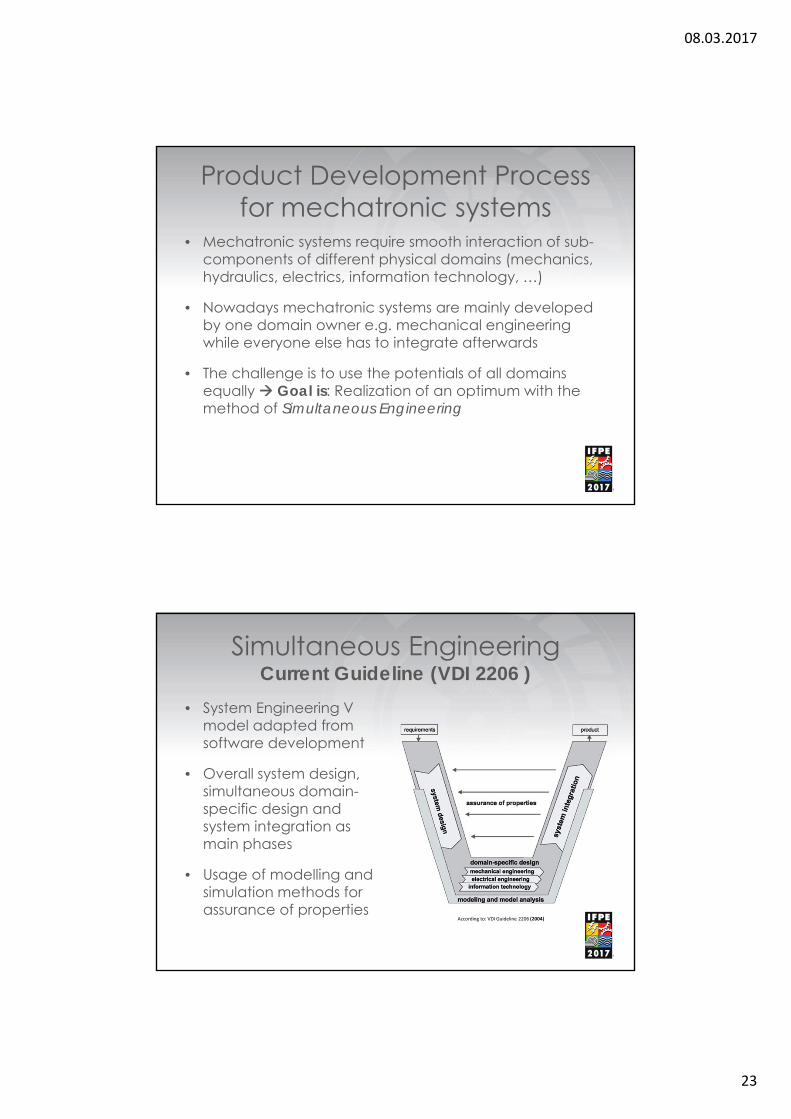
Simultaneous EngineeringCurrent Guideline (VDI 2206 )
• System Engineering V model adapted from software development
• Overall system design, simultaneous domain-specific design and system integration as main phases
• Usage of modelling and simulation methods for assurance of properties
According to: VDI Guideline 2206 (2004)
08.03.2017
24
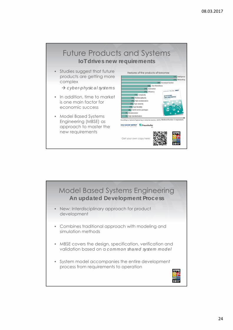
Future Products and SystemsIoT drives new requirements
• Studies suggest that future products are getting more complex cyber-physical systems
• In addition, time to market is one main factor for economic success
• Model Based Systems Engineering (MBSE) as approach to master the new requirements
Get your own copy here:
According to: Systems Engineering in industrial practice (2015)
Model Based Systems EngineeringAn updated Development Process
• New: Interdisciplinary approach for product development
• Combines traditional approach with modeling and simulation methods
• MBSE covers the design, specification, verification and validation based on a common shared system model
• System model accompanies the entire development process from requirements to operation

08.03.2017
25
VALIDATE
• Hydraulic drive and control and system simulation with the CAE tool “SIMSTER”
• Introduction to the new development method MBSE (philosophy and strategy)
• Requirements for MBSE (models, code generation, interfaces to real world)
Requirements for MBSESystem Simulation Perspective
• Tool chains simulation models
• Open, standardized inter-faces for model exchange between software tools
• Interfaces for hardware integration (HiL*) into simulations for virtual commissioning
Construction Assembly CommissioningDesign...
Assembly...
Model-based design HiL*Virtual
commissioning
t
DesignConstruc-tion
Commis-sioning
Model-Based Engineering
According to: Systems Engineering in industrial practice (2015)
* HiL - Hardware in the loop
08.03.2017
26
MBSE a (virtual) door openerVirtual commissioning
• Development and validation of PLC (controller) code using HiL*-simulation
• Early detection of errors in a safe environment
• Simultaneous design and virtual commissioning can result in optimized products
• Extended testing possibilities result in better product quality
According to: VDMA, Zukunftsprognose von ITQ auf Basis von Marktdaten (2010)
According to: VDW Bericht: Abteilungsübergreifende Projektierung komplexer Maschinen und Anlagen (1997)
* HiL - Hardware in the loop
MBSE for IoT applicationsVirtual Commissioning of the Smart Factory
• With IoT the focus is not only on single machines, but on entire plants and the connectivity between the machines (“Smart Factory”)
• For an efficient commissioning, an early validation of all IoT hardware and software components is desirable
– Is the data transfer working?– Does the data storage work properly (data bases, cloud services)?– Do the algorithms for the interpretation of the data run correctly?
• MBSE facilitates a virtual commissioning of IoTcomponents by providing data using the system models (digital twin of the plant)

08.03.2017
27
ConnectThe potentials of Connected Hydraulics
CONNECT• Potential of IoT Technologies for hydraulic
Systems
• Turning Hydraulic Drive Data into Information for essential use cases
• Data Sources (Drive Systems as “virtual” Sensors)
• Topology Scenarios (Where to put which Computing Power, Storage and User Interface?)

08.03.2017
28
Field Devices …
OPEN

08.03.2017
29
Stopbeing the
good slave
IoT Enabled

08.03.2017
30
communication +semantics
Alone …

08.03.2017
31
… or with partners?
Open = collaborative
08.03.2017
32
Open = innovative
Open = future-proof
08.03.2017
33
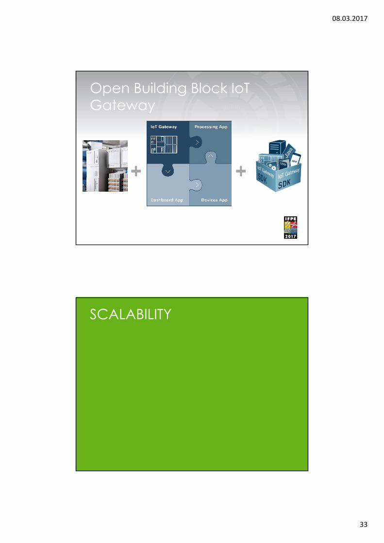
Open Building Block IoT Gateway
SCALABILITY
08.03.2017
34
Field
Cloud
Enterprise
…
…
…
SaaS
IaaS
PaaS
Storage Network SecurityCompute
GlobalTraceability
DynamiT MaintenanceSupport System
TraQ
Marketplace
Industry 4.0 Micro Services
AdditionalIndustry 4.0Application
AnalyticsPlatform
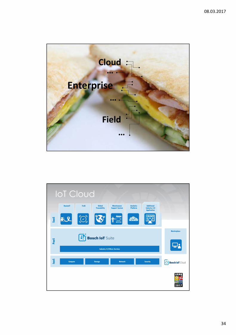
IoT Cloud

08.03.2017
35
Apps
Host
Core
Share
Apps
Host
Core
Share
Field Device ……….. Cloud
OEE
Availability Quality Performance
08.03.2017
36
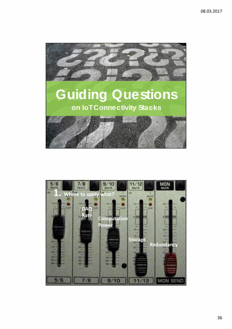
Guiding Questions on IoT Connectivity Stacks
Guiding Questions on IoT Connectivity Stacks
DAQ Rate
StorageRedundancy
Computation Power
1. Where to apply what?

08.03.2017
37
2. How to turn Data into Information?
3. How to stack?

08.03.2017
38
4. Where to put contextual User Interfaces?
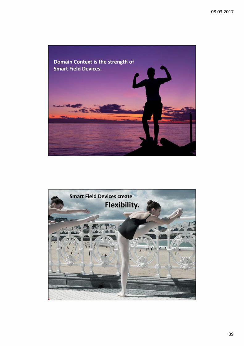
Scale by Evolution.
08.03.2017
39
Domain Context is the strength of Smart Field Devices.
Smart Field Devices create
Flexibility.

08.03.2017
40
(Hydraulic) Drives as virtual Sensors
USER CENTRIC

08.03.2017
41
People as Key Player
Building Block
Solution Set
08.03.2017
42
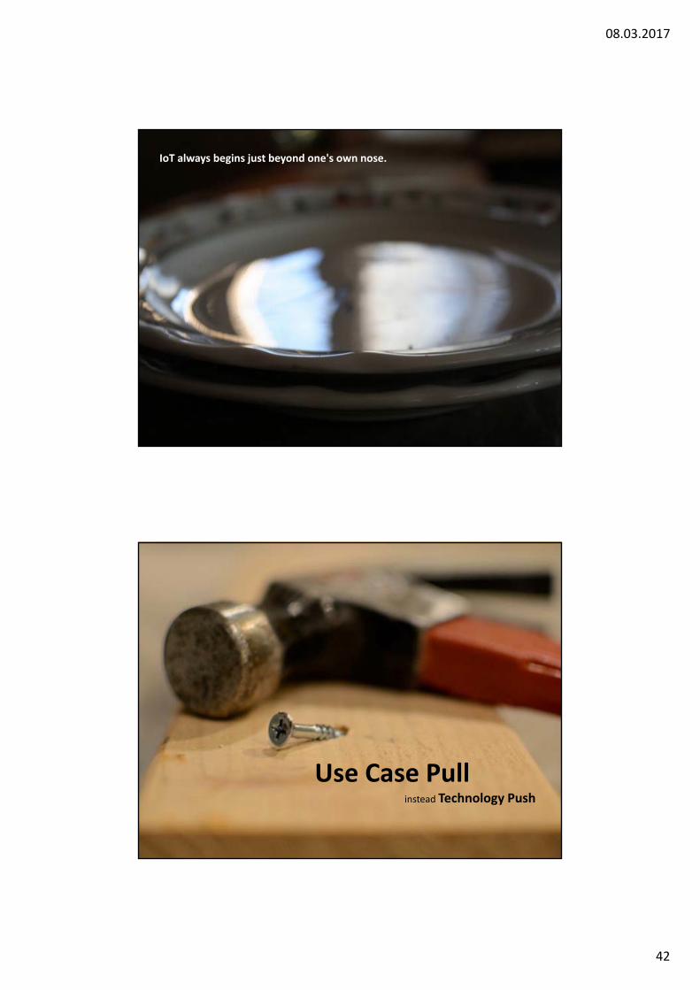
IoT always begins just beyond one's own nose.
Use Case Pull instead Technology Push

08.03.2017
43
Consult
Connect
Develop Solution Sets Systematically
Open = Future Proof
Scalable =Flexible
User Centric = Solution Focus
Potentials of Connected Hydraulics

08.03.2017
44
Questions?To earn Professional Development Hours (PDH):
▪ Log into the IFPE App▪ Go to this session in “Schedule”
▪ Check-In using the Slider in Session Detail
Please complete the session evaluation on the IFPE Mobile App▪ Go to Schedule and Select This Session
Follow UpsMeet us @IFPE - South Hall 3Booth - S80214
08.03.2017
45
[4] https://www.flickr.com/photos/wilhelmja/4233621497[6] Von Bengt Nyman - Flickr: DSC_9928, CC BY 2.0, https://commons.wikimedia.org/w/index.php?curid=30262299[8] https://www.flickr.com/photos/ofernandezberrios/2719757761/[9] https://www.flickr.com/photos/rightee/260024771/[10] https://www.flickr.com/photos/hernanpc/23218164373[11] https://www.flickr.com/photos/goldberg/107095332/[12] https://www.flickr.com/photos/manoftaste-de/9483602817[13] https://www.flickr.com/photos/osr/5770886035[16] https://www.flickr.com/photos/tamaranai/494821247[18] https://www.flickr.com/photos/shimgray/2803039423 Check Pattern[19] https://www.flickr.com/photos/grongar/8518902820 Temple[20] https://www.flickr.com/photos/debord/4932655275 Question Marks[21] https://www.flickr.com/photos/danja/249909161 Mixer[22] https://www.flickr.com/photos/unitedsoybean/13782241923/ Harvest[23] https://www.flickr.com/photos/jovanlaar/2137872208/ Puzzle[24] https://www.flickr.com/photos/nnova/2547506517[25] https://www.flickr.com/photos/133259498@N05/27458655072 Evolution[26] https://www.flickr.com/photos/46803151@N02/6113035626 Strength[27] https://www.flickr.com/photos/oneras/27898481016[31] https://www.flickr.com/photos/haru__q/14140861080[32] https://www.flickr.com/photos/matt1125/3677990005[33] https://www.flickr.com/photos/justinbaeder/5317820857/
Picture Sources - Connect
Abstract:State of the art hydraulic drives reached the same automation level as their electro mechanic brothers. The evolution of IoT (Industry 4.0) did not stop in front of hydraulics.
We will take you along for a user journey presenting the potentials of state-of the art technologies such as Electro-Hydraulic Drives, Simulation & IoT technologies:
Design: Consideration and System Configuration for Electrohydraulic Systems o Proportional Valve and Pump Drives, partners or competing technologieso Closed hydraulic circuits with frequency controlled pumps, challenges and solutionso Smart HPU’s, new technologies to make them small, intelligent and cost effective
Validate: Model-based Engineering and Electrohydraulic System Simulation o Introduction to the new development method MBE (philosophy and strategy)o Requirements for MBE (models, code generation, interfaces to real world)o Hydraulic drive and control and system simulation with the free tool “SIMSTER”
Connect: The potentials of connected Hydraulics o Potential of IoT Technologies for hydraulic Systemso Turning Hydraulic Drive Data into Information for essential use cases
• Efficient and user-oriented Commissioning• Process Optimization• Smart Maintenance
o Data Sources• Dedicated Sensors• Drive Systems as “virtual” Sensors (computed)• Sensor Nodes
o Topology Scenarios (Where to put which Computing Power, Storage and User Interface?)
The characteristics and advantages of these new approaches will be presented and proven by some live demonstrations.