electro-hydraulic cylinder: mini-motion package (mmp ...41 cylinders 42 cylinders electro-hydraulic...
TRANSCRIPT
41
Cylinders
42
Cylinders
Electro-Hydraulic Cylinder: Mini-Motion Package (MMP)
Explanation of the operating mechanism
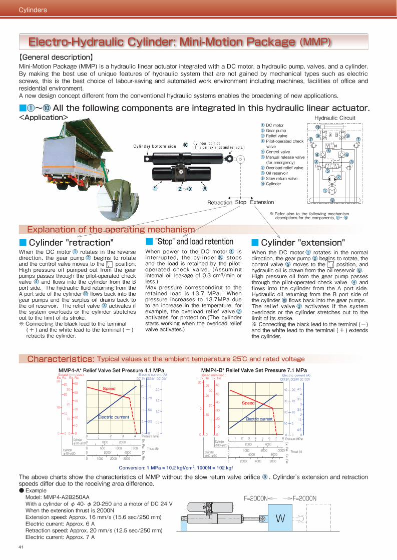
【General description】Mini-Motion Package (MMP) is a hydraulic linear actuator integrated with a DC motor, a hydraulic pump, valves, and a cylinder. By making the best use of unique features of hydraulic system that are not gained by mechanical types such as electric screws, this is the best choice of labour-saving and automated work environment including machines, facilities of office and residential environment. A new design concept different from the conventional hydraulic systems enables the broadening of new applications.
■ Cylinder "retraction" ■ "Stop" and load retention
Characteristics: Typical values at the ambient temperature 25℃ and rated voltage
■ Cylinder "extension"
Features
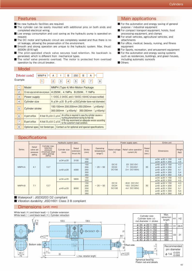
Dimensions (unit: mm)
■ For the automation and energy saving of general purpose / industrial equipment
■ For compact transport equipment, hoists, food processing equipment, and clamps
■ For small vehicles, agricultural vehicles, and attachments
■ For office, medical, beauty, nursing, and fitness equipment
■ For Sports, recreation, and amusement equipment■ For the automation and energy saving systems
such as residences, buildings, and green houses, including automatic sunroofs
■ Others
■ No new hydraulic facilities are required.■ The cylinder can be easily mounted with additional pins on both ends and
completed electrical wiring.■ Low energy consumption and cost saving as the hydraulic pump is operated on
request.■ The DC motor and hydraulic circuit are completely sealed and thus there is no
oil leakage, allowing the preservation of the environment.■ Smooth and strong operation are unique to the hydraulic system. Max. thrust:
8000N (816 kgf)■ The pilot-operated check valve secures load retention. No backlash is
generated, which is different from mechanical types.■ The relief valve prevents overload. The motor is protected from overload
operation by the circuit breaker.
Main applications
Specifications
Model
● ExampleModel: MMP4-A2B250AAWith a cylinder of φ 40- φ 20-250 and a motor of DC 24 VWhen the extension thrust is 2000NExtension speed: Approx. 16 mm/s (15.6 sec/250 mm)Electric current: Approx. 6 ARetraction speed: Approx. 20 mm/s (12.5 sec/250 mm)Electric current: Approx. 7 A
<Application>
■ Waterproof : JISD0203 D2 compliant■ Vibration durability: JISD1601 Class 3 B compliant
-0.025-0.068
Recommended pin diameter
φ14
Series
Hydraulic system spec. Power supply spec. Entire unit
Relief valve set pressure (MPa)
Cylinder max. retention pressure
(Overload relief valve setting)
(MPa)
Cylinder size (mm)
Rated extension thrust (N)
Stroke (mm)
Operating temperature
range℃
Rated voltage (V)
Relief valve operation current (A)
Rated time (sec.)
Dimensions Weight (kg))
MMP4-A 4.1 13.7
φ34-φ20 3100 150200
− 20 〜 50DC12DC24DC100
23(DC12V)11(DC24V)
2.4(DC100V)30
φ34- φ20 × 150φ34- φ20 × 200
4.24.5
φ40-φ20 4300
150200250300350
φ40- φ20 × 150φ40- φ20 × 200φ40- φ20 × 250φ40- φ20 × 300φ40- φ20 × 350
4.34.75.15.45.8
MMP4-B 7.1 13.7
φ34-φ20 5800 150200
− 20 〜 50DC12DC24DC100
40.8(DC12V)18.5(DC24V)4.4(DC100V)
30
φ34- φ20 × 150φ34- φ20 × 200
4.24.5
φ40-φ20 8000
150200250300350
φ40- φ20 × 150φ40- φ20 × 200φ40- φ20 × 250φ40- φ20 × 300φ40- φ20 × 350
4.34.75.15.45.8
When the DC motor ① rotates in the reverse direction, the gear pump ② begins to rotate and the control valve moves to the position. High pressure oil pumped out from the gear pumps passes through the pilot-operated check valve ④ and flows into the cylinder from the B port side. The hydraulic fluid returning from the A port side of the cylinder ⑩ flows back into the gear pumps and the surplus oil drains back to the oil reservoir. The relief valve ③ activates if the system overloads or the cylinder stretches out to the limit of its stroke.※ Connecting the black lead to the terminal
( + ) and the white lead to the terminal ( − ) retracts the cylinder.
Retraction ExtensionStop
▲
▲
① DC motor② Gear pump③ Relief valve④ Pilot-operated check
valve⑤ Control valve⑥ Manual release valve
(for emergency)⑦ Overload relief valve⑧ Oil reservoir⑨ Slow return valve⑩ Cylinder
When the DC motor ① rotates in the normal direction, the gear pump ② begins to rotate, the control valve ⑤ moves to the position, and hydraulic oil is drawn from the oil reservoir ⑧.High pressure oil from the gear pump passes through the pilot-operated check valve ④ and flows into the cylinder from the A port side. Hydraulic oil returning from the B port side of the cylinder ⑩ flows back into the gear pumps.The relief valve ③ activates if the system overloads or the cylinder stretches out to the limit of its stroke.※ Connecting the black lead to the terminal (−) and the white lead to the terminal ( + ) extends the cylinder.
When power to the DC motor ① is interrupted, the cyl inder ⑩ stops and the load is retained by the pilot-operated check valve. (Assuming internal oil leakage of 0.3 cm3/min or less.)Max pressure corresponding to the retained load is 13.7 MPa. When pressure increases to 13.7MPa due to an increase in the temperature, for example, the overload relief valve ⑦ activates for protection.(The cylinder starts working when the overload relief valve activates.)
※ Refer also to the following mechanism descriptions for the components, ①〜⑩
■①〜⑩ All the following components are integrated in this hydraulic linear actuator.Hydraulic Circuit
Cylinder sizeCylinder bore i.d.-
rod diameter × stroke
Max. retraction
lengthL
H1 H2
φ 34- φ 20 × 150 280 31 28.5φ 34- φ 20 × 200 330φ 40- φ 20 × 150 280
33 31φ 40- φ 20 × 200 330φ 40- φ 20 × 250 380φ 40- φ 20 × 300 430φ 40- φ 20 × 350 480
The above charts show the characteristics of MMP without the slow return valve orifice ⑨ . Cylinder's extension and retraction speeds differ due to the receiving area difference.
41
Cylinders
42
Cylinders
Electro-Hydraulic Cylinder: Mini-Motion Package (MMP)
Explanation of the operating mechanism
【General description】Mini-Motion Package (MMP) is a hydraulic linear actuator integrated with a DC motor, a hydraulic pump, valves, and a cylinder. By making the best use of unique features of hydraulic system that are not gained by mechanical types such as electric screws, this is the best choice of labour-saving and automated work environment including machines, facilities of office and residential environment. A new design concept different from the conventional hydraulic systems enables the broadening of new applications.
■ Cylinder "retraction" ■ "Stop" and load retention
Characteristics: Typical values at the ambient temperature 25℃ and rated voltage
■ Cylinder "extension"
Features
Dimensions (unit: mm)
■ For the automation and energy saving of general purpose / industrial equipment
■ For compact transport equipment, hoists, food processing equipment, and clamps
■ For small vehicles, agricultural vehicles, and attachments
■ For office, medical, beauty, nursing, and fitness equipment
■ For Sports, recreation, and amusement equipment■ For the automation and energy saving systems
such as residences, buildings, and green houses, including automatic sunroofs
■ Others
■ No new hydraulic facilities are required.■ The cylinder can be easily mounted with additional pins on both ends and
completed electrical wiring.■ Low energy consumption and cost saving as the hydraulic pump is operated on
request.■ The DC motor and hydraulic circuit are completely sealed and thus there is no
oil leakage, allowing the preservation of the environment.■ Smooth and strong operation are unique to the hydraulic system. Max. thrust:
8000N (816 kgf)■ The pilot-operated check valve secures load retention. No backlash is
generated, which is different from mechanical types.■ The relief valve prevents overload. The motor is protected from overload
operation by the circuit breaker.
Main applications
Specifications
Model
● ExampleModel: MMP4-A2B250AAWith a cylinder of φ 40- φ 20-250 and a motor of DC 24 VWhen the extension thrust is 2000NExtension speed: Approx. 16 mm/s (15.6 sec/250 mm)Electric current: Approx. 6 ARetraction speed: Approx. 20 mm/s (12.5 sec/250 mm)Electric current: Approx. 7 A
<Application>
■ Waterproof : JISD0203 D2 compliant■ Vibration durability: JISD1601 Class 3 B compliant
-0.025-0.068
Recommended pin diameter
φ14
Series
Hydraulic system spec. Power supply spec. Entire unit
Relief valve set pressure (MPa)
Cylinder max. retention pressure
(Overload relief valve setting)
(MPa)
Cylinder size (mm)
Rated extension thrust (N)
Stroke (mm)
Operating temperature
range℃
Rated voltage (V)
Relief valve operation current (A)
Rated time (sec.)
Dimensions Weight (kg))
MMP4-A 4.1 13.7
φ34-φ20 3100 150200
− 20 〜 50DC12DC24DC100
23(DC12V)11(DC24V)
2.4(DC100V)30
φ34- φ20 × 150φ34- φ20 × 200
4.24.5
φ40-φ20 4300
150200250300350
φ40- φ20 × 150φ40- φ20 × 200φ40- φ20 × 250φ40- φ20 × 300φ40- φ20 × 350
4.34.75.15.45.8
MMP4-B 7.1 13.7
φ34-φ20 5800 150200
− 20 〜 50DC12DC24DC100
40.8(DC12V)18.5(DC24V)4.4(DC100V)
30
φ34- φ20 × 150φ34- φ20 × 200
4.24.5
φ40-φ20 8000
150200250300350
φ40- φ20 × 150φ40- φ20 × 200φ40- φ20 × 250φ40- φ20 × 300φ40- φ20 × 350
4.34.75.15.45.8
When the DC motor ① rotates in the reverse direction, the gear pump ② begins to rotate and the control valve moves to the position. High pressure oil pumped out from the gear pumps passes through the pilot-operated check valve ④ and flows into the cylinder from the B port side. The hydraulic fluid returning from the A port side of the cylinder ⑩ flows back into the gear pumps and the surplus oil drains back to the oil reservoir. The relief valve ③ activates if the system overloads or the cylinder stretches out to the limit of its stroke.※ Connecting the black lead to the terminal
( + ) and the white lead to the terminal ( − ) retracts the cylinder.
Retraction ExtensionStop
▲
▲
① DC motor② Gear pump③ Relief valve④ Pilot-operated check
valve⑤ Control valve⑥ Manual release valve
(for emergency)⑦ Overload relief valve⑧ Oil reservoir⑨ Slow return valve⑩ Cylinder
When the DC motor ① rotates in the normal direction, the gear pump ② begins to rotate, the control valve ⑤ moves to the position, and hydraulic oil is drawn from the oil reservoir ⑧.High pressure oil from the gear pump passes through the pilot-operated check valve ④ and flows into the cylinder from the A port side. Hydraulic oil returning from the B port side of the cylinder ⑩ flows back into the gear pumps.The relief valve ③ activates if the system overloads or the cylinder stretches out to the limit of its stroke.※ Connecting the black lead to the terminal (−) and the white lead to the terminal ( + ) extends the cylinder.
When power to the DC motor ① is interrupted, the cyl inder ⑩ stops and the load is retained by the pilot-operated check valve. (Assuming internal oil leakage of 0.3 cm3/min or less.)Max pressure corresponding to the retained load is 13.7 MPa. When pressure increases to 13.7MPa due to an increase in the temperature, for example, the overload relief valve ⑦ activates for protection.(The cylinder starts working when the overload relief valve activates.)
※ Refer also to the following mechanism descriptions for the components, ①〜⑩
■①〜⑩ All the following components are integrated in this hydraulic linear actuator.Hydraulic Circuit
Cylinder sizeCylinder bore i.d.-
rod diameter × stroke
Max. retraction
lengthL
H1 H2
φ 34- φ 20 × 150 280 31 28.5φ 34- φ 20 × 200 330φ 40- φ 20 × 150 280
33 31φ 40- φ 20 × 200 330φ 40- φ 20 × 250 380φ 40- φ 20 × 300 430φ 40- φ 20 × 350 480
The above charts show the characteristics of MMP without the slow return valve orifice ⑨ . Cylinder's extension and retraction speeds differ due to the receiving area difference.
43
Cylinders
44
Cylinders
Caution on Selecting/Using ModelsSelect proper models according to the following selection procedure and check sheet:● MMP specifications and characteristic values are typical ones and may vary depending on operational conditions like the
temperature. Try to select the model with thrust and speed large enough to meet requested specifications.● Maximum internal leakage may amount to 0.3 cm3/min. Apply a mechanical lock for secure load retention.
■ Selection Procedure(1) Determine maximum thrust, maximum speed, power supply, and stroke required of an MMP cylinder from the application
and specifications of the equipment.(2) Select the relief valve set pressure, power supply, cylinder size, and cylinder stroke from the specifications and
characteristics of the selected MMP model.(3) Select orifices for port A and B from the load to be applied to the cylinder at page 44. A: Port A orifice (retraction load), B: Port B orifice (extension load), D: Port A and B orifices (retraction and extension load)(4) Electric wiring and Switching※ The customer should prepare the power supply and switching system. Please contact us for any details.
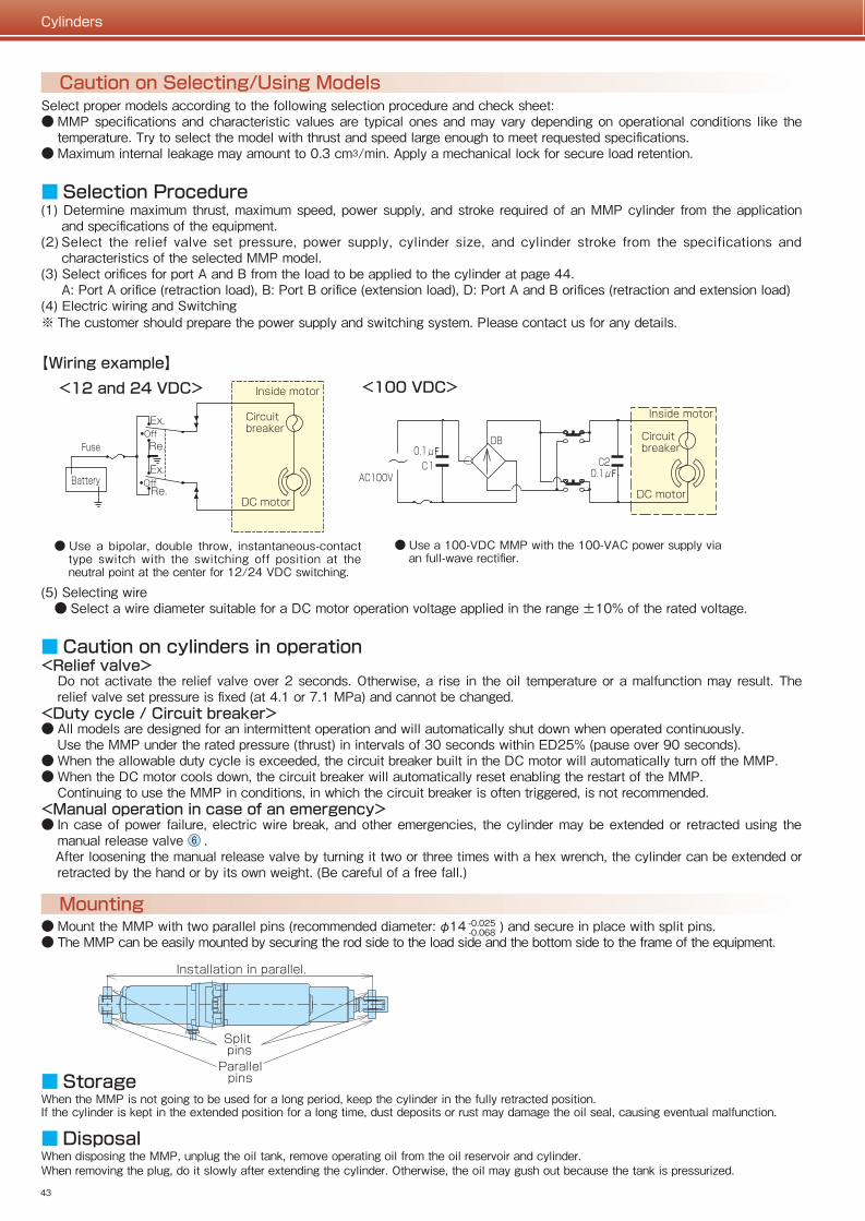
【Wiring example】
● Mount the MMP with two parallel pins (recommended diameter: φ14 ) and secure in place with split pins.● The MMP can be easily mounted by securing the rod side to the load side and the bottom side to the frame of the equipment.
■ Check sheet
■ StorageWhen the MMP is not going to be used for a long period, keep the cylinder in the fully retracted position.If the cylinder is kept in the extended position for a long time, dust deposits or rust may damage the oil seal, causing eventual malfunction.
■ DisposalWhen disposing the MMP, unplug the oil tank, remove operating oil from the oil reservoir and cylinder.When removing the plug, do it slowly after extending the cylinder. Otherwise, the oil may gush out because the tank is pressurized.
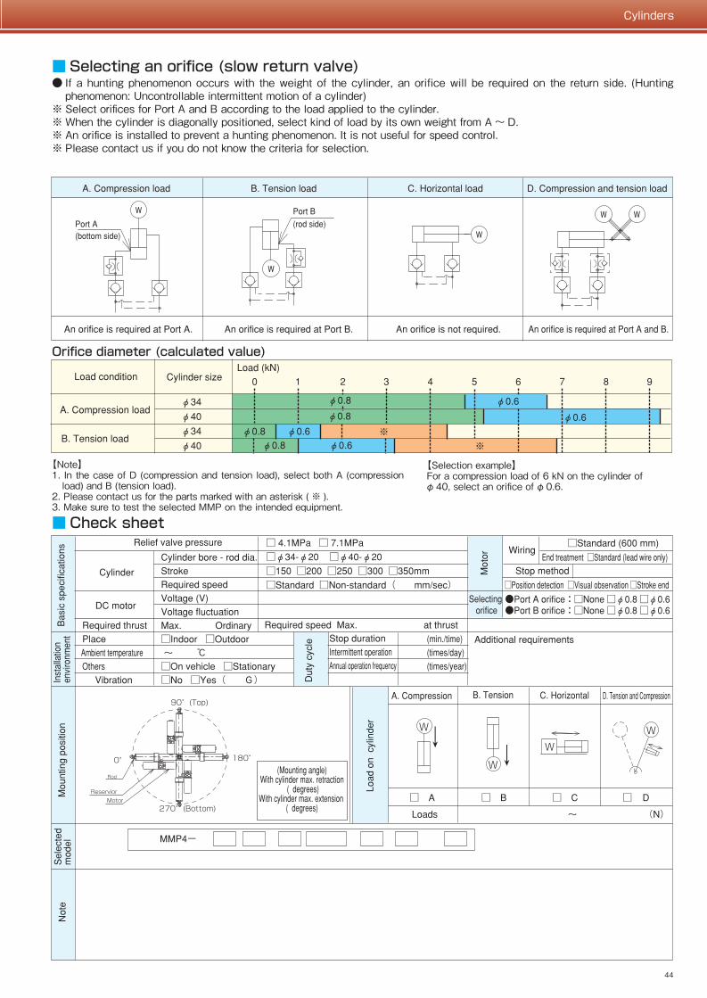
■ Selecting an orifice (slow return valve)● If a hunting phenomenon occurs with the weight of the cylinder, an orifice will be required on the return side. (Hunting
phenomenon: Uncontrollable intermittent motion of a cylinder)※ Select orifices for Port A and B according to the load applied to the cylinder.※ When the cylinder is diagonally positioned, select kind of load by its own weight from A 〜 D.※ An orifice is installed to prevent a hunting phenomenon. It is not useful for speed control.※ Please contact us if you do not know the criteria for selection.
【Selection example】For a compression load of 6 kN on the cylinder of φ40, select an orifice of φ0.6.
● Use a bipolar, double throw, instantaneous-contact type switch with the switching off position at the neutral point at the center for 12/24 VDC switching.
● Use a 100-VDC MMP with the 100-VAC power supply via an full-wave rectifier.
【Note】1. In the case of D (compression and tension load), select both A (compression
load) and B (tension load).2. Please contact us for the parts marked with an asterisk ( ※ ).3. Make sure to test the selected MMP on the intended equipment.
Orifice diameter (calculated value)
Mounting-0.025-0.068
(5) Selecting wire ● Select a wire diameter suitable for a DC motor operation voltage applied in the range ±10% of the rated voltage.
■ Caution on cylinders in operation<Relief valve>
Do not activate the relief valve over 2 seconds. Otherwise, a rise in the oil temperature or a malfunction may result. The relief valve set pressure is fixed (at 4.1 or 7.1 MPa) and cannot be changed.
<Duty cycle / Circuit breaker>● All models are designed for an intermittent operation and will automatically shut down when operated continuously. Use the MMP under the rated pressure (thrust) in intervals of 30 seconds within ED25% (pause over 90 seconds).● When the allowable duty cycle is exceeded, the circuit breaker built in the DC motor will automatically turn off the MMP.● When the DC motor cools down, the circuit breaker will automatically reset enabling the restart of the MMP. Continuing to use the MMP in conditions, in which the circuit breaker is often triggered, is not recommended.<Manual operation in case of an emergency>● In case of power failure, electric wire break, and other emergencies, the cylinder may be extended or retracted using the
manual release valve ⑥ . After loosening the manual release valve by turning it two or three times with a hex wrench, the cylinder can be extended or
retracted by the hand or by its own weight. (Be careful of a free fall.)
<12 and 24 VDC> <100 VDC>
43
Cylinders
44
Cylinders
Caution on Selecting/Using ModelsSelect proper models according to the following selection procedure and check sheet:● MMP specifications and characteristic values are typical ones and may vary depending on operational conditions like the
temperature. Try to select the model with thrust and speed large enough to meet requested specifications.● Maximum internal leakage may amount to 0.3 cm3/min. Apply a mechanical lock for secure load retention.
■ Selection Procedure(1) Determine maximum thrust, maximum speed, power supply, and stroke required of an MMP cylinder from the application
and specifications of the equipment.(2) Select the relief valve set pressure, power supply, cylinder size, and cylinder stroke from the specifications and
characteristics of the selected MMP model.(3) Select orifices for port A and B from the load to be applied to the cylinder at page 44. A: Port A orifice (retraction load), B: Port B orifice (extension load), D: Port A and B orifices (retraction and extension load)(4) Electric wiring and Switching※ The customer should prepare the power supply and switching system. Please contact us for any details.
【Wiring example】
● Mount the MMP with two parallel pins (recommended diameter: φ14 ) and secure in place with split pins.● The MMP can be easily mounted by securing the rod side to the load side and the bottom side to the frame of the equipment.
■ Check sheet
■ StorageWhen the MMP is not going to be used for a long period, keep the cylinder in the fully retracted position.If the cylinder is kept in the extended position for a long time, dust deposits or rust may damage the oil seal, causing eventual malfunction.
■ DisposalWhen disposing the MMP, unplug the oil tank, remove operating oil from the oil reservoir and cylinder.When removing the plug, do it slowly after extending the cylinder. Otherwise, the oil may gush out because the tank is pressurized.
■ Selecting an orifice (slow return valve)● If a hunting phenomenon occurs with the weight of the cylinder, an orifice will be required on the return side. (Hunting
phenomenon: Uncontrollable intermittent motion of a cylinder)※ Select orifices for Port A and B according to the load applied to the cylinder.※ When the cylinder is diagonally positioned, select kind of load by its own weight from A 〜 D.※ An orifice is installed to prevent a hunting phenomenon. It is not useful for speed control.※ Please contact us if you do not know the criteria for selection.
【Selection example】For a compression load of 6 kN on the cylinder of φ40, select an orifice of φ0.6.
● Use a bipolar, double throw, instantaneous-contact type switch with the switching off position at the neutral point at the center for 12/24 VDC switching.
● Use a 100-VDC MMP with the 100-VAC power supply via an full-wave rectifier.
【Note】1. In the case of D (compression and tension load), select both A (compression
load) and B (tension load).2. Please contact us for the parts marked with an asterisk ( ※ ).3. Make sure to test the selected MMP on the intended equipment.
Orifice diameter (calculated value)
Mounting-0.025-0.068
(5) Selecting wire ● Select a wire diameter suitable for a DC motor operation voltage applied in the range ±10% of the rated voltage.
■ Caution on cylinders in operation<Relief valve>
Do not activate the relief valve over 2 seconds. Otherwise, a rise in the oil temperature or a malfunction may result. The relief valve set pressure is fixed (at 4.1 or 7.1 MPa) and cannot be changed.
<Duty cycle / Circuit breaker>● All models are designed for an intermittent operation and will automatically shut down when operated continuously. Use the MMP under the rated pressure (thrust) in intervals of 30 seconds within ED25% (pause over 90 seconds).● When the allowable duty cycle is exceeded, the circuit breaker built in the DC motor will automatically turn off the MMP.● When the DC motor cools down, the circuit breaker will automatically reset enabling the restart of the MMP. Continuing to use the MMP in conditions, in which the circuit breaker is often triggered, is not recommended.<Manual operation in case of an emergency>● In case of power failure, electric wire break, and other emergencies, the cylinder may be extended or retracted using the
manual release valve ⑥ . After loosening the manual release valve by turning it two or three times with a hex wrench, the cylinder can be extended or
retracted by the hand or by its own weight. (Be careful of a free fall.)
<12 and 24 VDC> <100 VDC>