electride 2 - thebackshed … · · 2017-10-28electride 2.0 a small f77 interpreter with...
TRANSCRIPT

1
ELECTRIDE 2.0
A small F77 interpreter with datatypes, for pic32mx
S. Oliver © 2014, 2015, 2016
Document for current version: v2.0, pic32mx170B trial version 1.9x
March 2016
(Draft document)

2
Contents
0. Prefaces, and acknowledgements 5
1. Overview 7
2. Getting started : Hello World 8
3. Summary of operation. 10
The screen options and processing sequence. 10
The Input file 12
4. Variables, datatypes, arrays 13
Integer (INTEGER*4, INTEGER*2,INTEGER*1). 13
Floating point (REAL, DOUBLE). 14
Character (CHARACTER*1, CHARACTER*x) 15
Arrays 16
Variables in quantitative computing. 17
5. Operators, operands and intrinsic functions 19
Standard operators eg ( +, -, *, / and ** ). 19
Intrinsic math functions. 19
SIN, COS, TAN, ASIN, ACOS, ATAN, SQRT, ABS, RAND,
IFIX, FLOAT, DBLE, SNGL, ALOG, and EXP. 19
6. Subroutines, Functions and Common memory 22
SUBROUTINE 22
FUNCTION 24
COMMON 26
7. Program Control 29
CALL 29
CONTINUE 29
(DIMENSION) 29
DO 29
DO WHILE - END DO 31
END 31
GO TO 31
IF 32
IF THEN - ELSE IF - ELSE - END IF 34
RETURN 36
STOP 37

3
8. Input, Output, Format 38
READ 38
REAX 39
PRINT *, 39
WRITE ... 39
FORMAT 40
9. Port bit level access, LCD (16x2), and Keypad 45
Port I/O Bit access. 45
LCD 47
Keypad (4x4) 49
10. SPI (Serial Peripheral Interface) 58
11. Analog-Digital Converter 62
Analog measurements. 62
ADxx (single measurement) 62
ZADACQ (Fast burst of measurements). 65
12. Utilities 66
A) Non-Volatile Memory. 66
B) Code Integrity Check. 71
13. Bugs, Foibles, Exasperations so far and cop-outs ... 73
A1. Appendix 1 74
Error messages 74
Setting up 79
Configuration 80
Version limits 81
A2. Appendix 2 83
Some archetype examples, etc. 83
1. Keypad/LCD interface. 83
2. Time from DS3234 accurate clock chip using SPI . 83
3. Solar position calculation and display. 83
A3. Appendix 3 86
A) Vector graphic output ( Tektronix 4010 / Tera Term ). 86

4
[ Notes ]

5
0. Prefaces, and acknowledgements
Preface Version 2 :
Version 2 has had major additions and enhancements.
-- IF THEN, ELSE IF, ELSE and END IF commands
-- DO WHILE structure
-- IF/WHILE logic clause recursion
-- Character string-type datatypes
-- Input file line structure improvements
-- Fast burst-mode AD conversions
-- Auxiliary input for reading streamed data eg GPS
-- LCD commands for keypad interaction
-- COMMON memory block
-- A Serial Peripheral Interface based channel
-- Non-volatile (eeprom) user memory
-- Code integrity check
-- Tektronix 4010 vector output
At this stage the 28-pin version is running out of pins. A version is running on a pic32mx795
and will be the development direction along with a pic32mx470 and hopefully the MZ.
As before, the example thumbnails and outputs are cut-and-paste from a terminal session
using the interpreter, with the proviso that the longer programs’ contents are from the text
source for better formatting. The examples are included as files. The appendix has some
further working examples, again using the current version, that reflect some of the usual
operations of embedded processing.

6
Preface Version 1
Originally this started as something in assembler, to experiment with writing math routines
for pic microcontrollers. Along the way it was moved to C; as the initial project ended, the
Microchip math libraries were switched in, and the instructions became more and more like
a simple language. So the experiment became, to see how viable a small fortran interpreter
for pic32mx was, and what level microcontroller would be needed.
Of course, an interpreted language offering double precision could be seen as over-done.
And yet, there is a need for small amounts of precise calculation, a wish for grass-roots
development, and concern that education is bypassing quantitative skills...So I hope it is
useful. It is not meant to be a finished work, but is at a reasonable stagepoint at least.
I have cherry-picked quite a few good ideas, and certainly do not claim to be the originator
of them. The problem is, in an extensive and ill-defined industry, knowing where the ideas
came from or where I saw them. Many articles (SC, EPE, Circuit Cellar) with dozens of
authors, on using Microchip pics starting with the 16F84...The Microchip
documentation...The C language and K&R of course...and the excellent books by Lucio di
Jasio. Electride itself is written in C using the Microchip MPLABX / GCC, with helpful
assistance from Microchip support. The core algorithm used is of course van Djykstra's
famous shunting-yard method, explained on Chris Jones’ website.
And from IT history, the visionary MONEC system in the mid seventies...running Fortran
and Basic jobs for hundreds of students. I recently found out, it ran on a PDP11 with 32k
memory. Amazing.
Iconic examples are included as a traditional salute. This document is provisional at this
stage, however the examples and outputs are cut-and-paste mainly from actual sessions
using the actual version (with a few slightly abbreviated).
Bibliography
Programming 16 bit microcontrollers in C (2007)
Di Jasio, L.
Programming 32 bit microcontrollers in C (2008)
Di Jasio, L.
The C Programming Language, (1978, 1988) second edition (ANSI).
Kernighan, BW and Ritchie, DM.
and from time
An Introduction to Computer Programming in Fortran (Monecs Fortran) (1976)
Bellamy, CJ (dec) and Whitehouse, LG.
---------------------------------------------------------------

7
1. Overview
Electride is an embedded interpreter, that runs on PIC32MX chips.
It will load, run and store small programs written in a subset of Fortran 77 very similar to
Basic. The programs can easily use high level math and access the chip hardware, for
example, to run A/D measurements and display results. Integer (32, 16 and 8 bit), single and
double precision (32 and 64) floating point, and character based datatypes can be used as
required.
It can be connected to a serial terminal or run standalone. Typically a PC with something
like Tera Term and a serial-usb pathway can be used, and/or hardware with a LCD display,
button switches and so on. The Tektronix 4010 emulator in Tera Term can be used for simple
vector graphics.
At startup a simple menu allows interaction with the user. If a program is already present
and there is no serial connection during startup, the stored program will be run
automatically.
The trial version is intended for entry-level use and has constraints. It runs on a
PIC32MX170B 28-pin sdip IC. Other versions scale over the pic 32MX range. The appendix
has more details.
---------------------------------------------------------------

8
2. Getting started : Hello World
As a starting exercise, it is usual to load and run the (iconic) "helloworld" program.
Initially connect the Electride/pic32 board, switch it on, and run the PC terminal software.
Hitting <enter> on the keyboard will show the banner and simple menu list, something like :
ELECTRIDE 2.0 © S. Oliver 2014, 2015, 2016
with content ©Microchip and ©GCC
Trial PIC32MX170B version 1.9X
(G) Get (L) List
(S) Save (A) Analyse
(R) Run (C) Comp (res)
>
You are now interacting with the board, the ‘>’ prompt is the sign that the system is ready
for you to select an option.
The R option will run a user program that is already in place. A new chip will not have any
user program already loaded. So for this exercise, your first step will be to load the example
“hello world” program.
To load a program, use the option “G” ie “Get”. This sets the board to expect the new
program. You will see a "Waiting.." prompt as the board then waits for the program to be
sent.
>G
Waiting..
Using the PC windows environment now, send the program file, using the Tera Term menu
item. It is the "Send File..." (not Transfer) item in Tera Term. A file picker will let you
navigate to and select the file.
"OK" is then displayed as feedback that the sending is complete.
>G
Waiting..
OK

9
The menu list then returns. It is a good idea to select S and save the program.
A "save.." confirmation will be displayed and the menu list returns.
>S
save..
Now select R to run the program. The program is displayed first, followed by its output as
it runs. After it finishes the pic32mx is reset and memory refreshed, and the menu and
prompt return.
>R
PROGRAM helloworld
C
PRINT *, "Hello, world"
END
\
Hello, world
rrefresh..
The first "r" is displayed as the reset starts, and the "refresh" displayed as the user program
is reloaded from saved memory.
The example is mainly a PRINT statement, which simply prints strings and variables in their
default format. So, as an exercise you can easily alter the text string and see the result. Open
the file with a text editor, add your initials inside the quotes, and save. On repeating the
above steps you should see your new content printed.

10
3. Summary of operation.
The screen options and processing sequence.
At the top level, the menu and prompt stay in a loop waiting for user input.
The options are G (Get), S (Save), R (Run), L (List), A (Analyse) and C (Comp).
Selecting “G” will set up reception of a user program as described before. The user program
is read into memory ( ie volatile memory ) where it can be processed.
Selecting “S” will save the contents of the memory – ie the user program – to permanent
memory, where it is non-volatile and is preserved during power switch off.
The option “R” is the main item and runs the user program. It is discussed in detail below.
Selecting “L” will list the program, ie, copy it to the console screen. This keeps the
indentation intact which assists readability.
“A” will display a few program details, useful mainly for a section described later, and “C”
is Compile and not active.
Running a user program.
Selecting “R” in the menu will start the interpreter processing the user program.
As a first stage, the interpreter runs through the program in an initial pass. This does some
compacting and simple input checking, and also sets up some structure, eg the loops and
subprogram entry points. The following main pass then steps through the program,
tokenising and then processing each line in depth.
Lines that are commands or program control statements usually have specific parsing and
are described in the specific sections. In general commands are not recursive.
Lines with a leading assignment ( "=" ) are assumed to be equations. These are processed as
usual by evaluating the right hand side and assigning the result to the variable on the left
hand side.
To process equations, initially the line is scanned for user functions and these are evaluated
to results. The main line processing then starts by arranging the tokens into the appropriate
sequence. The operands that are hard-coded digits, or ascii in single quotes, are converted
on-the-fly to internal form using the most likely datatype. For a group of digits, if no
decimal point is present, the group is provisionally converted to a 32-bit signed integer. If a
decimal point is present, double precision floating point is used instead. If the input group
further contains the characters "e" or "d" it is assumed to be exponential format. For quote-

11
contained ascii characters, a group is assumed to be concatenated characters as in a string,
and a single character treated as a single byte character.
The sequence is then processed and evaluates to a result.
The left hand side of the equation is then used to provide a datatype and memory location.
The result is converted as necessary and the value stored at the memory location.
Eg
PROGRAM integer4
C
INTEGER*4 i
i = 1222333444
PRINT *, i
END
\
1222333444
When the end of the program is reached, a software reset is initiated. This sets a clean start
for the next run. The program is then reloaded from eeprom, and the focus returns to the
console and prompt as described before.

12
The Input file
The program file itself is ordinary text, using a subset of ascii characters.
Keywords and commands in statements are in uppercase, with lowercase used for variables.
Lines are in the fortran layout. The first part of a line is set-column, so the first six column
positions are reserved for specific use.
The first is reserved for a comment flag (C), which allows the rest of the line to be used for
comment text. The second and sixth columns are reserved. The third, fourth, and fifth
positions on a line can be used for an optional identifying statement number (numerical
label). The line content then usually starts at the seventh column.
For clarity, (in general) lines can be indented using spaces after the six preset columns. The
List (L) menu option shows lines keeping the indentation in place.
Tabs, control characters etc should not be used. A line can be left blank (with no spaces) for
improved readability.
The main program optionally starts with a PROGRAM statement, and finishes with an END
statement. Any subroutine and function definitions then follow, each starting with the
name declaration and finishing with an END statement.
A backslash (\) is used to signal the end of the file.
It is suggested that a file extension ".f7" be used to differentiate the file from other text files.
The examples used are included as files and are a good starting point.
---------------------------------------------------------------

13
4. Variables, datatypes, arrays
Integer (INTEGER*4, INTEGER*2,INTEGER*1)
Floating point (REAL, DOUBLE)
Character (CHARACTER*1, CHARACTER*x)
Variables must be declared before they can be used. The declaration specifies which
datatype to use, followed by the variable name(s). A variable name is comprised of
lowercase ascii characters, with the first six characters used as the unique identifier.
Variables are not “automatic”, and must be unique.
The datatype associated with a variable determines how that variable's data is
processed and held in memory. Accordingly the datatypes provided allow the use of
integer, floating point, and character variables. A character datatype may consist of a single
byte or alternatively can set a string length.
In general, variables and arrays are local in scope unless specifically cited otherwise..
Note unless the name of a variable is stored as a token, it has to be interpreted every time it
is used, so short names are more efficient.
Integer (INTEGER*4, INTEGER*2,INTEGER*1).
Integer data is processed using the intrinsic 32-bit word size and integer arithmetic, and uses
memory according to the specified byte count, eg an INTEGER*4 uses 4 bytes of memory.
>R
PROGRAM integer4
C
INTEGER*4 i
i = 1222333444
PRINT *, i
END
\
1222333444
To conserve memory INTEGER*1 and INTEGER*2 can be used, which require 1 and 2 bytes
respectively and hold smaller values. INTEGER*8 may be added in future.

14
Floating point (REAL, DOUBLE).
Floating point data is processed using either one word (datatype REAL: single precision) or
two words (datatype DOUBLE: double precision). REAL provides precision of six significant
figures and is held in 4 bytes of memory, DOUBLE gives twelve significant figures and uses
8 bytes.
PROGRAM real
C
REAL a
a = 1.123456
PRINT *, "a = ", a
END
\
a = 1.123456
PROGRAM double
C
DOUBLE a
a = 1.12345678
PRINT *, "a = ", a
END
\
a = 1.12345678
Exponential input format can also be used eg
PROGRAM doubleexp
C
DOUBLE a
a = 1.12d3
PRINT *, "a = ", a
END
\
a = 1120.00000000

15
Character (CHARACTER*1, CHARACTER*x)
If the datatype specifies one byte, the data is processed and stored as ascii in a single byte.
If the datatype specifies more than one byte, multiple bytes are used in a contiguous
sequence including an additional null byte “bookend”.
PROGRAM charact
C
CHARACTER*1 a
a = 'G'
PRINT *, "a is ", a
END
\
a is G
PROGRAM charactmult
C
CHARACTER*16 txtstr(3)
txtstr(1) = 'Hello, world! '
txtstr(2) = 'live long '
txtstr(3) = 'and prosper'
PRINT *, txtstr(1), txtstr(2), txtstr(3)
END
\
Hello, world! live long and prosper
The datatype also determines the default reporting format. Integers are reported with as
many digits as required. Six (rounded) decimal places are presented by default for REALs,
and eight for DOUBLEs.
This can present an inconvenient reminder of the precision limits eg
PROGRAM realish
C
REAL a
a = 1000.20
PRINT *, "a = ", a
END
\
a = 1000.200012

16
Specific formatting can be used for reporting with suitable definition, for example, a
temperature reading may have resolution of 0.1 at best.
PROGRAM temperaturereal
C
REAL celsius, fahr, step
INTEGER*4 i
FORMAT (2F6.1,/)
step = 20.0
fahr = 0.0
DO 10 i = 1, 11
fahr = fahr + step
celsius = 5.0 * ( fahr - 32.0 ) / 9.0
WRITE (6,0) fahr, celsius
10 CONTINUE
END
\
20.0 -6.7
40.0 4.4
60.0 15.6
80.0 26.7
100.0 37.8
120.0 48.9
140.0 60.0
160.0 71.1
180.0 82.2
200.0 93.3
220.0 104.4
For clarity the examples will often use the default reporting until specific formatting is
covered later.
Arrays
Arrays are declared much the same way as single variables, with the declation also
specifying the dimension extents. The total number of elements possible is set by the
available memory. There is a maximum of three dimensions.
An array element is identified by an index of either an integer value or by a simple variable
that has a valid integer value. Index numbering starts at 1. Variables used as an index must
be datatype integer*4. Index values outside the declared extent are trapped as errors at
runtime.
Memory is reserved by each declaration line in four-byte chunks, so an array declaration
is more efficient than multiple lines of variables.

17
PROGRAM birdlife
C
INTEGER*4 birds(3)
birds(1) = 123456
birds(2) = 314153
birds(3) = 987654
PRINT *, "There are ", birds(1), " buzzards"
PRINT *, "There are ", birds(2), " eagles"
PRINT *, "There are ", birds(3), " turkeys"
END
\
There are 123456 buzzards
There are 314153 eagles
There are 987654 turkeys
Note that the array is used as one token , ie without spaces.
Variables in quantitative computing.
The point of a computer being “digital” (as opposed to analogue) – that is, using Boolean
(binary) logic - is that it preserves information integrity across operations and is immune to
noise, small level fluctuations, and so on. The information is processed using the underlying
hardware, which is designed specifically for that purpose.
As integers (within range) can be used and stored efficiently and exactly, it makes sense to
use integer variables where possible. In this case, it is a 32-bit processor, so a 32-bit range for
data and operations is usual. Memory access is routinely 32-bit and can also be accessed
down to the byte level. Subsequently the integer variables provided use 4, 2, or 1 bytes.
Fractional quantities are often required, and in this case floating point techniques are used
instead. These have a much greater flexibility, with the caveat that they are usually are not
exact or as fast.
Incorrect technique can cause problems. An example is when a large value is used as a
baseline, and a much smaller value is added. The summation in floating-point may not have
the available range to utilise many significant figures of the smaller number. A similar
example is subtracting two almost identical numbers. The result will have lost most of the
significant digits, even if integers are being used.
In standard 32 bit IT systems single-precision floating point values are accurate to about one
part in 16 million - ie a little under seven significant figures for the positive values. In many
cases this is not enough or is at least inconvenient. As an illustration it is interesting to try
adding the fraction one ten-thousandth, 10000 times, to a starting point of 2500.0, on a
standard single precision system...the returned answer will almost certainly be 2500.0, not
the correct 2501.0 as might have been expected.

18
Double precision can help in some situations. It is accurate to twelve significant figures, and
takes a little extra time to process. Here is "realish" upgraded :
PROGRAM doubleish
C
DOUBLE a
a = 1000.20000000
PRINT *, "a = ", a
END
\
a = 1000.20000000
The following program simulates (not very well) float-charging a battery for three hours.
The cell already has 10 amp-hours stored, and there is a milliamp charging. The summation
fails with single precision but can be rescued with DOUBLE ( as a quick fix before a
rethink.. ).
PROGRAM battery
C
INTEGER*4 sec
DOUBLE start, stored, current, gain
C
C Initial state in amp-seconds
C
start = 36000.0
stored = start
C
C Three hours adding at one milliamp
C
current = 0.001
DO 10 sec = 1, 10800
stored = stored + current
10 CONTINUE
C
gain = stored - start
FORMAT (A,F5.3,/)
WRITE (6,0) "amp-seconds gained : ", gain
END
\
amp-seconds gained : 10.800
Often, as in this case, a need for double precision can be avoided by a suitable change in
methodology, but sometimes it is vital.
* Do not over charge lithium cells !!
---------------------------------------------------------------

19
5. Operators, operands and intrinsic functions
Standard operators eg ( +, -, *, / and ** ).
The standard operators (+, -, *, / and **) are used as normal. Some popular operators from C
are also included ie >>, <<, &, |, and ~. The relation operators ( <, <=, =, !=, >=, > and && or ||
) used for logic are covered later in the program control IF… section.
If required, brackets can be used to enforce evaluation sequence. Concatenated
exponentiation should be made unambiguous with brackets.
Operands can be simple numbers, variable identifiers, array identifiers (with subscripts of
either simple integers or integer variable identifiers), or the resultants of other operations in
the normal math precedence
The underlying routines use double precision math. Inadverdently mixing integer and
floating point arithmetic is an error, unless the datatype is deliberately overridden. Note that
to hard-code a negative number, the negate operator is used, ie (currently) a space is needed
between the “-“ and the number.
Intrinsic math functions.
SIN, COS, TAN, ASIN, ACOS, ATAN, SQRT, ABS, RAND, IFIX, FLOAT, DBLE,
SNGL, ALOG, and EXP.
In general the intrinsic functions SIN, COS, TAN, ASIN, ACOS, ATAN, SQRT, ABS, RAND,
IFIX, FLOAT, DBLE, SNGL, ALOG, and EXP are used as normal, with the proviso that
uppercase is used. They can be used as operators, ie, brackets are optional. Complex
formulae should be broken down into sections to fit.
Math functions and output
SIN Sin of input value (radians)
COS Cos of input value (radians)
TAN Tan of input value (radians)
ASIN Arcsin in radians of input value (double)
ACOS Arccos in radians of input value (double)
ATAN Arctan in radians of input value (double)

20
SQRT Square root of input value
ABS Absolute value
RAND Random integer, 0 - 65565.
ALOG Natural logarithm
EXP e to the power x.
IFIX Integer value of floating point input
FLOAT Floating point (single precision) equivalent of integer
DBLE Double precision equivalent of input
SNGL Single precision equivalent of double
The RAND function requires a dummy integer*4 argument.
Intrinsic functions are also used for reading a digitized analog value via the A-D converter
(ADxx) and reading input pin states (BRxx). They return integer*2 values and are covered in
a later section.
Character-based operations.
Two character strings, or a character string and a single character, can be “added” to form
an output string. The output maximum width is set by the datatype definition. Character
strings can also tested for equivalence or non-equivalence using the standard operators.
To assist reading text input, there are two conversion functions :
ATOI Converts character string to integer
ATODB Converts character string to double precision float
The examples illustrate the use of some operators and intrinsic functions.
The first has some (very) simple math expressions showing precedence.
The appendix has further examples, one using a function and some popular C operators for
bit shifting ( LCD clock ), and another using fairly complex arithmetic and double precision
to calculate solar position at a known location and time.
-------------------------------------------------------------------

21
1) Simple math expressions showing precedence
PROGRAM mathexp
C
INTEGER*4 a, b, c
REAL x, y, z
FORMAT (A,F4.2,A,/)
a = 1
WRITE "a = ", a
b = 1 + 2
WRITE "b = ", b
c = b + b
PRINT *, "c = ", c
a = 1 * 2 + 3
PRINT *, "a = ", a
a = 1 + 2 * 3
PRINT *, "a = ", a
a = 1 + b * 3
PRINT *, "a = ", a
a = ( 1 + b ) * 3
PRINT *, "a = ", a
x = 0.500
y = SIN ( x ) + COS ( x )
PRINT *, "y = ", y
z = FLOAT ( ADX1 )
z = ( z * 3.260 ) / 1024.0
PRINT *, "z = ", z , " volts"
WRITE (6,0) "z = ", z , " volts"
END
\
a = 1
b = 3
c = 6
a = 5
a = 7
a = 10
a = 12
y = 1.357008
z = 0.248320 volts
z = 0.25 volts

22
6. Subroutines, Functions and Common memory
User subroutines and functions can be defined and used as necessary, and act as reusable
code. This is useful for frequently used program segments and promotes a logical structure.
Information is exchanged via variables cited in the call to the subroutine.
Otherwise, variables are local to the subroutine invocation and are declared as normal.
In addition a group of variables in a main program or subroutines can be set to use an area
of memory in common, that is, also used by similar groups of variables in other subroutines.
This expands their scope and can greatly conserve memory.
The definitions are placed after the main program, start with the SUBROUTINE or
FUNCTION statement, and finish with an END statement. A RETURN statement must be
present. They are initially read by the interpreter in a pre-emptive pass and subsequently
used when the subroutine/function is active.
Functions must return a value, and consequently the definition of a function must specify
the return value datatype.
SUBROUTINE
A subroutine is instigated by a CALL statement in the main program.
Control returns to the calling program with the RETURN statement.
PROGRAM startup
C
INTEGER*1 j
j = 9
PRINT *, "OK to start"
CALL righto ( )
PRINT *, "j = " , j
END
C
SUBROUTINE righto ( )
INTEGER*1 j
j = 42
PRINT *, "Righto"
PRINT *, "sub j = " , j
RETURN
END
\
OK to start
Righto
sub j = 42
j = 9

23
The subroutine definition can also include formal arguments, that is, parameters that are
variables used to pass data. Calls to invoke the subroutine must then also include the
matching actual arguments, to a maximum of eight.
The parameters are variable identifiers that are passed as call-by-reference, that is, the
memory locations used by the actual variables in the call are then also used by the
correlating formal arguments set in the subroutine definition. So any changes made by the
subroutine will automatically persist after the subroutine finishes. This also means scarce
memory is conserved.
PROGRAM subaddten C
PRINT *, "Start"
INTEGER*2 x
x = 7
PRINT *, "x = ", x
CALL addten ( x )
PRINT *, "x now = ", x
END
C
SUBROUTINE addten ( a )
PRINT *, "start subroutine"
a = a + 10
PRINT *, "end subroutine"
RETURN
END
\
Start
x = 7
start subroutine
end subroutine
x now = 17
In many systems, when a variable or array name is cited in a call to a subroutine, critical
properties are not necessarily known and so a further definition of some sort (eg a
DIMENSION statement) is then required. Sometimes the variable is simply redeclared in the
subroutine. Electride uses the pre-existing attributes of the variable or array and so the
additional definition is not required. To maintain compatibility, such variables can be
redeclared as usual but any changed details will be ignored.
If required, array index ranges can be passed to the subroutine at call time using simple
integer variables in the argument list. This is useful as the subroutine can then be used
again in other programs without having to edit it each time.
Subroutines can be nested four deep and called recursively. They must not have the same
name as a variable or array.

24
Note that as the parameters in the call are expected to be variables, using a numerical value
instead is often not the best practice.
FUNCTION
User-defined Functions are a specialised form of subroutine and defined much the same
way, with the addition of specifying the datatype.
When executing, the function automatically has the use of a variable of the same name and
datatype, with the contents being returned to the calling statement.
Note that functions have been implemented with some concessions and simplifications.
They are evaluated left-to-right in the statement sequence before the rest of the statement is
processed, and a total of four can be called in one statement. To simplify the parsing a little,
a single token is used to handle a user function call and the cited variables, which means the
function call may not include spaces before/inside the parentheses. Functions are available
in equations, ie not in commands and IF clauses.
Note that it used to be considered a programming error for a call to cite a numerical value
instead of a variable. As a safeguard in Electride the value is passed as call-by-value. That is,
the value will be passed to the function as the value of the corresponding formal variable,
and the data discarded when the function finishes.
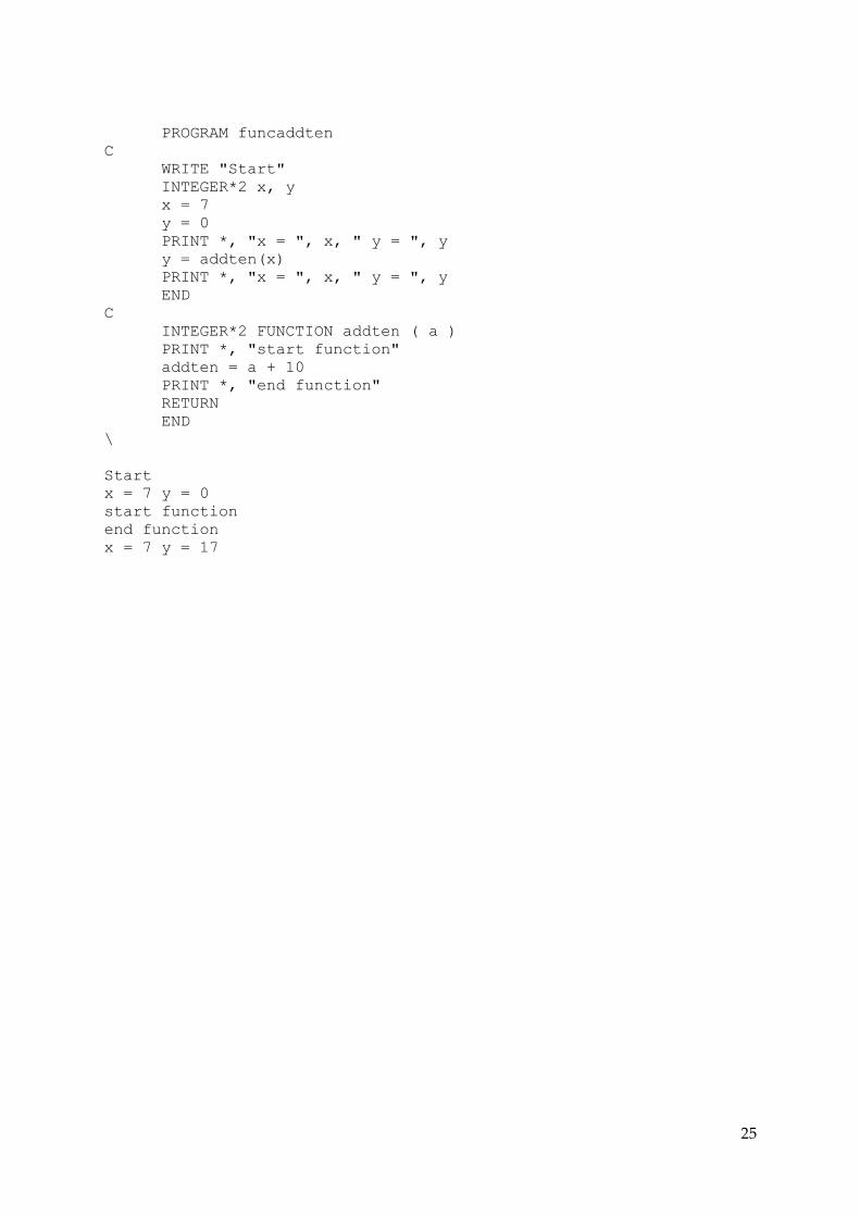
In the following example the subroutine above is implemented as a function.
The examples section has further examples using subroutines and functions extensively.
25
PROGRAM funcaddten
C
WRITE "Start"
INTEGER*2 x, y
x = 7
y = 0
PRINT *, "x = ", x, " y = ", y
y = addten(x)
PRINT *, "x = ", x, " y = ", y
END
C
INTEGER*2 FUNCTION addten ( a )
PRINT *, "start function"
addten = a + 10
PRINT *, "end function"
RETURN
END
\
Start
x = 7 y = 0
start function
end function
x = 7 y = 17

26
COMMON
As well as passing variables using the call arguments, selected groups of variables can be
set to use a block of memory that is common to the main program and some subroutines.
The values in the memory are then global to the main program and the relevant subroutines.
The groups of variables using this block must each have exactly the same datatypes and
sequence and must be declared at the start ie before other variables are defined.
The basic COMMON command that is available for compiled programs is used. However
for efficiency in an interpreter the command works a little differently. Instead of acting on
the variables cited individually in turn, COMMON will act on all the variables declared up
to that point in the subroutine as a set.
In general it can be seen how the command frees up the argument list, but at the expense of
readability. It is recommended that the variables are cited in the command lines, as usual, as
documentation. The null keyword COMBLK can be used to include multiple lines.
The example is the program from before, now changed to use a variable in COMMON.
The further example shows a program and two subroutines, with three variables using
common memory access, and also using a local and a passed variable.
PROGRAM subaddtencommn
C
PRINT *, "Start"
INTEGER*2 x
COMMON x
x = 7
PRINT *, "x = ", x
CALL addten ( )
PRINT *, "x now = ", x
END
C
SUBROUTINE addten ( )
INTEGER*2 a
COMMON a
PRINT *, "start subroutine"
a = a + 10
PRINT *, "end subroutine"
RETURN
END
\
Start
x = 7
start subroutine
end subroutine
x now = 17

27
PROGRAM demcommon
INTEGER*4 a, b, c
COMMON a, b, c
INTEGER*4 d, z
C
PRINT "Start .."
a = 17
b = 3
c = 44
d = 71
z = 93
PRINT " common ", " local ", " passed "
PRINT " eg a b c ", " d ", " z "
PRINT "starting values:"
PRINT " ",a," ", b," ", c," ", d," ", z
CALL subwun ( )
PRINT "values main level now:"
PRINT " ",a," ", b," ", c," ", d," ", z
CALL subtoo ( z )
PRINT "values main level now:"
PRINT " ",a," ", b," ", c," ", d," ", z
PRINT "Ok finish "
END
C
C
SUBROUTINE subwun ( )
INTEGER*4 s, t, u
COMMON s, t, u
PRINT "call.."
s = 31
t = 1
u = 48
PRINT "values in sub"
PRINT " ",s," ", t," ", u
PRINT "return.."
RETURN
END
C
SUBROUTINE subtoo ( x )
INTEGER*4 g, j, k
COMMON g, j, k
INTEGER*4 m, x
PRINT "call.."
g = 12
j = 9
k = 25
m = 67
x = 55
PRINT "values in sub"
PRINT " ",g," ", j," ", k," ", m," ", x
PRINT "return.."
RETURN
END
\

28
Start ..
common local passed
eg a b c d z
starting values:
17 3 44 71 93
call..
values in sub
31 1 48
return..
values main level now:
31 1 48 71 93
call..
values in sub
12 9 25 67 55
return..
values main level now:
12 9 25 71 55
Ok finish
---------------------------------------------------------------

29
7. Program Control
CALL
CONTINUE
(DIMENSION)
DO
DO WHILE - END DO
END
GO TO
IF
IF THEN - ELSE IF - ELSE - END IF
RETURN
STOP
CALL
Calls a subroutine.
This is covered in the subroutine section.
CONTINUE
Continues program processing.
(DIMENSION)
Array datatype and dimensions are automatically carried through to subroutines and
functions so a DIMENSION statement is not required.
Furthermore redimensioning arrays in memory is not in the project scope. So, for source
compatability, programs can include a DIMENSION statement, but it is not active.
DO
A DO statement initiates a repeated loop. The standard form has parameters detailing the
loop iteration, and the alternative DO WHILE form repeats while a logical test evaluates to
true.
The standard DO statement specifies the loop end statement, the variable to use as a
counter, the start count, the end point count, and optionally the increment value. The loop
end statement is identified by a numerical label and must be within the program or

30
subroutine. The count parameters can be numbers or integer variables (four byte), and the
increment value defaults to 1 if not set.
PROGRAM doloop
C
INTEGER*4 count, start, finish
PRINT *, "do loop"
start = 4
finish = 8
DO 10 count = start, finish
PRINT *, "count = ", count
10 CONTINUE
END
\
do loop
count = 4
count = 5
count = 6
count = 7
count = 8
Loops can be nested in multiple levels, with a limit set by the software version.
The same loop terminal statement can be used by multiple standard-form loop levels. The
loop end must not be a branching statement or a do-while end and it is strongly
recommended, at least for this format, that a CONTINUE is used as a convention.
PROGRAM doloops
C
INTEGER*4 i, j, k
PRINT *, "Yo! Loops! "
DO 10 i = 1, 2
DO 10 j = 1, 2
DO 10 k = 1, 2
PRINT *, "Like.. i=", i," j=", j," k=", k
10 CONTINUE
END
\
Yo! Loops!
Like.. i=1 j=1 k=1
Like.. i=1 j=1 k=2
Like.. i=1 j=2 k=1
Like.. i=1 j=2 k=2
Like.. i=2 j=1 k=1
Like.. i=2 j=1 k=2
Like.. i=2 j=2 k=1
Like.. i=2 j=2 k=2

31
DO WHILE - END DO
A DO WHILE loop is similar to the standard DO form, however the statement includes a
logical test. If the test returns true the loop is instigated, and then is repeated while the test
remains true. The loop range is to the associated END DO statement.
PROGRAM dowhile
C
INTEGER*4 count
PRINT *, "Start.."
count = 1
DO WHILE ( count < 4 )
PRINT *, "count ", count
count = count + 1
END DO
PRINT *, "Finito"
END
\
Start..
count 1
count 2
count 3
Finito
DO-WHILE loops can be nested in multiple levels, with a limit set by the software version.
Each DO -WHILE loop must have a separate END-DO terminal statement.
To prevent ambiguity, END DO statements may not have numerical labels and so cannot be
used to terminate standard-form loops.
It can be a good idea to indent lines with spaces for clarity. Do not use tabs. The “L” (List)
option in the menu will show the lines in the indented format.
END
Marks the end of the main program section or following subroutine or function.
GO TO
A GO TO command unconditionally transfers program flow to the destination statement,
which must have a numerical label id. The destination must be within the local program /
subroutine / function.

32
Note that, the original standard requires that a GO TO statement within a loop can transfer
to a statement that is apparently outside the loop, (past the loop end point) and then jump
back again with the loop state still remaining active. So, existing loop ranges and states,
tests etc remain in place even if a GO TO apparently exits the loop. It is strongly
recommended that GO TOs be avoided if possible, or at least destinations kept very local
and within any loop or IF block.
PROGRAM goto
C
PRINT *, "Right On !"
GO TO 10
PRINT *, "What ??"
10 PRINT *, "Dig it !"
END
\
Right On !
Dig it !
IF IF THEN - ELSE IF
IF statements allow conditional branches and processing.
An embedded test clause is evaluated and determines further action. For evaluation, the test
is passed to the equation processor, and the returned value '0' used for false and != 0 for
true. The clause may not start with an operator.
There are two forms, as the original IF single-line statement was extended to add a multiline
IF .. THEN ... END IF form.
Single line IF.
The single-line type has a IF keyword with a test (condition) before the rest of the line. If the
test evaluates to true, the rest of the line is processed. The rest of the line is usually a simple
assignment, a call to a subroutine or a return, a command to set a port pin state, or a GO TO.
The tests are for conditions of
equal-to ( = ),
not-equal-to ( != ),
less-than ( < ),
less-than-or-equal-to ( <= ),
greater-than ( > ),
greater-than-or-equal-to ( >= ).

33
The older versions were
equal-to ( .EQ. ),
not-equal-to ( .NE. ),
less-than ( .LT. ),
less-than-or-equal-to ( .LE. ),
greater-than ( .GT. ),
greater-than-or-equal-to ( .GE. ).
The clause is evaluated to a result with zero signifying false and not-zero signifying true.
The evaluation can recurse three or seven tokens in a standard sequence and can use logical
operators :
and ( && )
or ( || ).
PROGRAM liftoff C
INTEGER*4 altitude, stage
PRINT *, "Ignition..."
PRINT *, "Lift off !"
stage = 1
DO 10 altitude = 0, 100, 10
IF ( altitude > 10 ) stage = 2
IF ( altitude > 70 ) stage = 3
PRINT *, "Stage ", stage, " and altitude ", altitude
10 CONTINUE
END
\
Ignition...
Lift off !
Stage 1 and altitude 0
Stage 1 and altitude 10
Stage 2 and altitude 20
Stage 2 and altitude 30
Stage 2 and altitude 40
Stage 2 and altitude 50
Stage 2 and altitude 60
Stage 2 and altitude 70
Stage 3 and altitude 80
Stage 3 and altitude 90
Stage 3 and altitude 100

34
PROGRAM ifeqand
C
INTEGER*4 i, j
PRINT *, "start.."
i = 5
j = 28
PRINT *, "j = ", j
IF ( i = 5 && j = 28 ) PRINT *, "Ok"
IF ( i = 5 && j != 28 ) PRINT *, "bad"
j = 24
PRINT *, "j = ", j
IF ( i = 5 && j = 28 ) PRINT *, "Ok"
IF ( i = 5 && j != 28 ) PRINT *, "bad"
PRINT *, "FINISH "
END
C
\
start..
j = 28
Ok
j = 24
bad
FINISH
IF THEN - ELSE IF - ELSE - END IF
The multiline form has an initial IF … THEN statement and an associated END IF.
The IF… THEN command includes the test, and conditionally runs through the following
lines until the END IF statement is reached.
>L
PROGRAM ifthen
C
INTEGER*4 count
PRINT *, "Start.."
DO 10 count = 1, 2
IF ( count = 1 ) THEN
PRINT *, "Itsa one.."
END IF
10 CONTINUE
PRINT *, "Finito"
END
\
Start..
Itsa one..
Finito

35
Specific alternative conditions can optionally be included using ELSE IF's.
>L
PROGRAM ifthenelseif
C
INTEGER*4 count
PRINT *, "Start.."
DO 10 count = 1, 3
IF ( count = 1 ) THEN
PRINT *, "Itsa one.."
ELSE IF ( count = 2 ) THEN
PRINT *, "Itsa two.."
ELSE IF ( count = 3 ) THEN
PRINT *, "Itsa three.."
END IF
10 CONTINUE
PRINT *, "Finito"
END
\
Start..
Itsa one..
Itsa two..
Itsa three..
Finito
An ELSE provides a generic alternative.
>L
PROGRAM ifthenelse
C
INTEGER*4 count
PRINT *, "Start.."
DO 10 count = 1, 2
IF ( count = 1 ) THEN
PRINT *, "Itsa one.."
ELSE
PRINT *, "whaat.."
END IF
10 CONTINUE
PRINT *, "Finito"
END
\
Start..
Itsa one..
whaat..
Finito

36
The full combo :
>L
PROGRAM ifthenelseifelse
C
INTEGER*4 count
PRINT *, "Start.."
DO 10 count = 1, 4
IF ( count = 1 ) THEN
PRINT *, "Itsa one.."
ELSE IF ( count = 2 ) THEN
PRINT *, "Itsa two.."
ELSE IF ( count = 3 ) THEN
PRINT *, "Itsa three.."
ELSE
PRINT *, "whaat.."
END IF
10 CONTINUE
PRINT *, "Finito"
END
\
Start..
Itsa one..
Itsa two..
Itsa three..
whaat..
Finito
RETURN
Returns from a subroutine or function.
This is covered in the subroutine section.

37
STOP
A historical command which prints STOP on the console and stops execution. The main use
was for program development. Here this returns to the reset and menu sequence.
PROGRAM stop
C
INTEGER*4 count
PRINT *, "Start.."
count = 1
DO WHILE ( count < 4 )
PRINT *, "count ", count
count = count + 1
END DO
STOP
PRINT *, "Finito"
END
\
Start..
count 1
count 2
count 3
STOP
---------------------------------------------------------------

38
8. Input, Output, Format
READ (input) and WRITE/PRINT (output) commands are used for higher level I/O. A subset
of f77 is used as a template. Lower level access that uses bit setting and specific peripheral
modules, and the defined commands used are covered in the next section.
At an entry level, the READ and WRITE commands use defaults for details and data
formatting. For more specific control, optional information can be used to set the required
parameters.
The basic commands using the defaults are described first. The I/O is assumed to use the
chip uart, connected to a serial terminal (console).
READ
A READ command reads input eg from the console and ends on a carriage return. Commas
are used to separate multiple items. The text input is then converted to values, using the
datatype of the variables specified. If a negative sign is required it must be the first character
in each field.
eg
PROGRAM readmult
C
REAL a, b
INTEGER*2 c
PRINT *, "Input for a, b, c ?"
READ a, b, c
PRINT *, a, " ", b, " ", c
END
\
Input for a, b, c ?
3.141,2.3456,789
3.141000 2.345600 789

39
REAX
A similar command reads from an auxiliary serial input. In this case it is designed to fish a
record out of streaming ascii, so will wait for the next end-of-line in the stream and then
read the following line as the input. It will self-complete automatically after a second or so
and the program resumes, if nothing has been found the input will be blank.
Eg
REAX a, b, c, d, e, f, g, h, p, j
IF ( a = '$GPRMC' ) THEN
IF ( c = 'A' ) THEN
timedb = ATODB b
…
date = ATOI j
…
PRINT *,
WRITE ...
A PRINT or WRITE command sends the values of variables to output. The datatype of each
variable determines the default format used. Quoted text strings can be included.
The shorter versions can be used for convenience,
PRINT "a = ", a
WRITE "a = ", a
or asterisks can be included to formally signify default values.
PRINT *, "a = ", a
WRITE (*,*) "a = ", a

40
Example with default formats :
PROGRAM defaultformat
C
INTEGER*1 a
INTEGER*2 b
INTEGER*4 c
REAL d
DOUBLE e
CHARACTER*1 f
CHARACTER*15 g
a = 32
b = 4321
c = 1222333444
d = 1.123456
e = 1.12345678
f = 'Y'
g = 'Hello, world'
PRINT *, "start"
PRINT *, "a = ", a
PRINT *, "b = ", b
PRINT *, "c = ", c
PRINT *, "d = ", d
PRINT *, "e = ", e
PRINT *, "f = ", f
PRINT *, "g = ", g
PRINT *, "finish"
END
\
start
a = 32
b = 4321
c = 1222333444
d = 1.123456
e = 1.12345678
f = Y
g = Hello, world
finish
FORMAT
FORMAT sets the descriptors used for specific formatting.
Formatted I/O requires a format descriptor to use for each variable. The format descriptors
are stored as a sequential list using a FORMAT statement. When the WRITE command is
processed, each variable is examined and output in turn, using the next format descriptor in
the list. If the format list finishes, it is re-used as necessary.

41
Accordingly the WRITE command includes two extra parameters to identify in turn the
output hardware or file type (eg, a user terminal or disk), and the format list, before the
variables to use.
The first WRITE parameter, the number identifying the file/hardware type, can be set as '6'
(user terminal) or left as '*' at this stage.
The second WRITE parameter specifies which format list to use.
In larger systems multiple formats can be active, so an integer is cited which identifies which
format statement to use. In this version the requirements are simpler, so a zero ( '0' ) is cited
instead, which determines that the most recent format statement is to be used.
Format descriptors are short strings citing I (integer), F (floating point), E (exponential) and
A (alphanumeric). The letter is followed by numbers for the number of digits and decimal
places.
Eg
I6 Integer field of six digits.
F6.2 Real number with six digits and two decimal places.
E20.4 Real number with four decimal places and exponent.
A1 One ASCII character.
A Cited text string.
A number before the descriptor will repeat it. Other characters in a format descriptor are
passed to the underlying C format command. If necessary the descriptors can be separated
by simple actions to some extent, eg, an X will insert a space, and a forward slash (/)
specifies an end-of-record which will output a carriage return/newline and rewind the list.
The numeric output fields are right-justified with blanked leading zeros, text output fields (
A* format) are left justified and padded with spaces.
Cited text strings (to 32 characters) can be included in the variable list and must have a
matching single A format.

42
Example of specific formatting :
PROGRAM specformat
C
INTEGER*4 a
REAL b
DOUBLE c
CHARACTER*1 d, e, f, g
CHARACTER*7 h
a = 1222333444
b = 3.12345678
c = 45.12345678
d = 'T'
e = 'H'
f = 'E'
g = ' '
h = 'Yo!'
WRITE "start"
C
WRITE h
C
FORMAT (I10,/)
WRITE (6,0) a
C
a = 1234
WRITE (6,0) a
WRITE (6,0) a, a, a
C
FORMAT (3I10,/)
WRITE (6,0) a, a, a
C
FORMAT (F8.6,/)
WRITE (6,0) b
FORMAT (F8.2,/)
WRITE (6,0) b
FORMAT (F10.8,/)
WRITE (6,0) c
FORMAT (A,F5.3,A,/)
WRITE (6,0) "The value of c is ", c, " degrees. "
C
FORMAT (E10.8,/)
WRITE (6,0) c
FORMAT (E20.4,/)
WRITE (6,0) c
C
FORMAT (A7,A7)
WRITE (6,0) h, h
C
FORMAT (A1)
WRITE (6,0) d, e, f, g
WRITE "finish"
END
\

43
start
Yo!
1222333444
1234
1234
1234
1234
1234 1234 1234
3.123457
3.12
45.12345678
The value of c is 45.123 degrees.
4.51234568e+01
4.5123e+01
Yo! Yo! THE finish
Repetition using an implied loop.
A WRITE statement can acess array elements using an implied loop. This is useful with
repeat descriptors.
Eg
FORMAT (64A1,/)
WRITE (6,0) ( page(x,y), x = 1, 64 )
Here the A1 descriptor is used 64 times before the next line, as the index variable x
increments from 1 through 64. So, this will print 64 characters from the array and then start
the next line.
Note that with an implied loop the list must be enclosed in brackets. Currently there is a
limit of one implied loop per write statement. It must follow non-loop variables.
For some 'retro' eighties lineprinter artwork, the example subroutine prints a page of 64x21
characters row by row using an array. In this case it has been prefilled with a simple sine
curve and axes.
…
… C
SUBROUTINE plott ( page )
INTEGER*4 x, y
FORMAT (64A1,/)
DO 40 y = 1, 21
WRITE (6,0) ( page(x,y), x = 1, 64 )
40 CONTINUE
RETURN
END
\

44
start
!--------------------------------------------------------------!
! **** !
! *** *** !
! ** ** !
! ** ** !
! * * !
! * ** !
! ** * !
! * * !
!* * !
!--------------------------------------------------------------!
! ** *!
! * ** !
! * * !
! * * !
! ** ** !
! * * !
! ** ** !
! **** *** !
! **** !
!--------------------------------------------------------------!
finish
---------------------------------------------------------------

45
9. Port bit level access, LCD (16x2), and Keypad
Low-level access and peripherals ie port bits, LCD (16x2), and keypads can be used.
Port I/O Bit access.
Port pins (bits) are set, or read, with the Bxxx commands.
Setting a pin state:
To set a port pin state on or off, the relevant bit is set up or down :
BDXY Bit Down on port X pin Y
BUXY Bit Up on port X pin Y
eg
BDB5 set port B bit 5 low.
and BUB5 will set it high.
so to blip a pin
PROGRAM pinblipd
C
10 BUB5
BDB5
GO TO 10
END
\
The visible effect here is that a led connected to B5 will be apparently partially lit as it is set
on and off rapidly.
Reading a pin state :
Similarly a port pin state can be read using R instead. The command acts as a function
returning an integer value.
eg n = BRB5
will read port B pin 5 and return 1 or 0 as appropriate.

46
So to indicate if B8 is high or low using B2 as an indicator :
PROGRAM pinled
C
DO WHILE ( 1 )
IF ( BRB8 = 1 ) BUB2
IF ( BRB8 = 0 ) BDB2
END DO
C
END
\
The traditional flash-led program uses a delay to be visible.
PROGRAM flashled
C
DO WHILE ( 1 )
BUB5
CALL delay ( )
BDB5
CALL delay ( )
END DO
END
C
SUBROUTINE delay ( )
INTEGER*4 i
DO 10 i = 1, 2000
10 CONTINUE
RETURN
END
\
In the '170 version the sixteen port B pins (B0 – BF) are accessible. The port 'B' identifier is
automatically set so the B is ignored and a generic X can be used instead.
Bear in mind that although port states persist after a program ends, they will be cleared
when the chip is reset, so you may not see the effects unless the program keeps running in a
loop. Also remember the console output is on B4, so a led on that will usually be lit.

47
LCD
LCD output is set up for the standard Hitachi-compatible 16x2 LCD modules.
LCDSTRT
To use the module, firstly it is started and initialized with the LCDSTRT command.
LCDPRNT
The command LCDPRNT xxx… will then write to the display. The LCDPRNT is very
similar to the PRINT or WRITE using default formats and is used the same way. After
LCDPRNT the cursor returns to the start of the first line.
PROGRAM lcdhello
C
LCDSTRT
LCDPRNT "Hello, world "
END
\
LCDNWLN
To move to the next line, the command LCDNWLN is used, and the following LCDPRNT
then writes to the next line.
PROGRAM lcdhello2line
C
LCDSTRT
LCDPRNT "Hello, world "
LCDNWLN
LCDPRNT "Yeah, baby !! "
END
\
It is a good idea to pad with extra space characters, to ensure a refresh of the full line.
The modules are fairly slow at processing and refreshing, so if continuous updating is used
a delay may be needed for legibility.
Using LCDPRNN (no T) instead of LCDPRNT will leave the cursor at the current position, ie
the next print will append to the existing text. A backspace command LCDBSPC will
backspace the LCD and delete the last character.

48
As there is limited space, floating point numbers are displayed with a conservative format
with two decimal places (REAL) and three decimal places (DOUBLE) respectively.
PROGRAM lcdvar C
REAL a
DOUBLE b
LCDSTRT
LCDPRNT " "
LCDNWLN
LCDPRNT " "
a = 3.542
b = 5.876
LCDPRNT "a = ", a
LCDNWLN
LCDPRNT "b = ", b
END
\

49
Keypad (4x4)
The basic port pin set/read commands can be used to read key presses on a keypad.
To use a keypad, the 4x4 grid lines are connected to eight port B pins. Four are connected to
input port pins on the pic32 and are held low with resistors. The other four are connected
to output port pins on the pic32 and are each in turn set high by the pic32. Any key press
then connects one output to one of four possible inputs and brings it high.
To read the pad, a suitable routine is called which stays in a loop, setting the output pins
high in sequence and polling the possible input pins. When an input pin is high, then the
relevant key is pressed and the routine then returns the key value. A time delay is used for
some simple de-bounce filtering.
The example subroutine sets the ‘*’ (asterisk) as a decimal point, the ‘#’ (hash) as a negative
sign, the ‘A’ as a delete/backspace, and the ‘D’ as the return/enter key. So each keypress
returns an ASCII character.
To input a number, it is assembled from the ASCII keypresses into a multicharacter string
and converted to the numeric value. The further examples illustrates combined keypad
and LCD use.
The pin details, wiring etc, are arbitrary depending on version and so are detailed further
in the appendix.

50
Example – a keypad access subroutine
SUBROUTINE retkey ( r )
r = '?'
BDBF
BDBE
BDBD
BDBC
BDBB
BDBA
BDB9
BDB8
C
DO WHILE ( r = '?' )
BDB8
BUBB
IF ( BRBF ) r = '1'
IF ( BRBE ) r = '2'
IF ( BRBD ) r = '3'
IF ( BRBC ) r = 'A'
BDBB
BUBA
IF ( BRBF ) r = '4'
IF ( BRBE ) r = '5'
IF ( BRBD ) r = '6'
IF ( BRBC ) r = 'B'
BDBA
BUB9
IF ( BRBF ) r = '7'
IF ( BRBE ) r = '8'
IF ( BRBD ) r = '9'
IF ( BRBC ) r = 'C'
BDB9
BUB8
IF ( BRBF ) r = '.'
IF ( BRBE ) r = '0'
IF ( BRBD ) r = '-'
IF ( BRBC ) r = 'D'
END DO
CALL delay()
RETURN
END

51
Example – a simple choice list using the keypad and LCD.
(With apologies to Dr Suess)
PROGRAM fishkeylcd
CHARACTER*1 d
LCDSTRT
LCDPRNT " "
LCDNWLN
LCDPRNT " "
d = '?'
DO WHILE ( d != 'D' )
PRINT "Choose 2,3,B,C?"
LCDPRNT "Choose 2,3,B,C?"
CALL retkey ( d )
PRINT d
IF ( d = '2' ) THEN
CALL twofish()
ELSE IF ( d = '3' ) THEN
CALL threefish()
ELSE IF ( d = 'B' ) THEN
CALL bluefish()
ELSE IF ( d = 'C' ) THEN
CALL seafish()
END IF
END DO
LCDPRNT " "
LCDNWLN
LCDPRNT " "
END
SUBROUTINE twofish ( )
PRINT "Two fish !!"
LCDNWLN
LCDPRNT "Two fish !! "
RETURN
END
SUBROUTINE threefish ( )
PRINT "Three fish !!"
LCDNWLN
LCDPRNT "Three fish !! "
RETURN
END
SUBROUTINE bluefish ( )
PRINT "Blue fish !!"

52
LCDNWLN
LCDPRNT "Blue fish !! "
RETURN
END
SUBROUTINE seafish ( )
PRINT "Sea fish !!"
LCDNWLN
LCDPRNT "Sea fish !! "
RETURN
END
SUBROUTINE retkey ( r )
r = '?'
BDBF
BDBE
BDBD
BDBC
BDBB
BDBA
BDB9
BDB8
DO WHILE ( r = '?' )
BDB8
BUBB
IF ( BRBF ) r = '1'
IF ( BRBE ) r = '2'
IF ( BRBD ) r = '3'
IF ( BRBC ) r = 'A'
BDBB
BUBA
IF ( BRBF ) r = '4'
IF ( BRBE ) r = '5'
IF ( BRBD ) r = '6'
IF ( BRBC ) r = 'B'
BDBA
BUB9
IF ( BRBF ) r = '7'
IF ( BRBE ) r = '8'
IF ( BRBD ) r = '9'
IF ( BRBC ) r = 'C'
BDB9
BUB8
IF ( BRBF ) r = '.'
IF ( BRBE ) r = '0'
IF ( BRBD ) r = '-'
IF ( BRBC ) r = 'D'
END DO
CALL delay()
RETURN

53
END
SUBROUTINE delay ( )
INTEGER*4 i
DO 10 i = 1, 3000
10 CONTINUE
RETURN
END
\
Choose 2,3,B,C?
1
Choose 2,3,B,C?
2
Two fish !!
Choose 2,3,B,C?
3
Three fish !!
Choose 2,3,B,C?
A
Choose 2,3,B,C?
B
Blue fish !!
Choose 2,3,B,C?
C
Sea fish !!
Choose 2,3,B,C?
D

54
Example – keypad and LCD with backspace.
Here the user is prompted for a number. The LCD is updated as the keypad keys are
pressed for feedback. The user is entering pi – 3.141 – and makes a mistake, hitting 5 instead
of 4. The backspace key “A” is used to delete the 5, and the 4 is entered. When the user is
finished the “D” is pressed (the OK signal) and the final number string is shown on the
LCD. The console also shows the keypress sequence and also, as a check, the actual
numerical value that is stored in the variable.
CCCCCCCCCCCCCCCCCCCCCCCCCCCCCCCCCCCCCCCCCCCCCCCCCCCCCCCCCCCC
C
PROGRAM getnum
C
C reads 4x4 keypad, shows chars on lcd
C keypad assumes lines are low until scanned
C so pull-down resistors are used
C
CCCCCCCCCCCCCCCCCCCCCCCCCCCCCCCCCCCCCCCCCCCCCCCCCCCCCCCCCCCC
CHARACTER*16 val
INTEGER*4 i, j
DOUBLE flo
CHARACTER*1 d, res(16)
FORMAT (A1,/)
d = ' '
res(1) = ' '
i = 1
C Init lcd, prompt user
LCDSTRT
LCDPRNT " "
LCDNWLN
LCDPRNT " "
LCDPRNT "Input number ? "
LCDNWLN
C Build numeric string from keypresses
C Display each key press as it occurs
C Loop until OK key then display full string
C Echo to console
C
C Key A is backspace/delete
C Key * is decimal point
C Key hash is negative sign
C Key D is end-of-input ie OK

55
CALL retkey ( d )
res(i) = d
DO WHILE ( res(i) != 'D' )
WRITE (6,0) res(i)
IF ( res(i) = 'A' ) THEN
LCDBSPC
i = i - 1
res(i) = ' '
ELSE
LCDPRNN res(i)
i = i + 1
END IF
CALL retkey ( d )
res(i) = d
END DO
FORMAT (10A1,/)
res(i) = ' '
WRITE (6,0) ( res(j), j = 1, 10 )
C check full result
LCDPRNT " "
LCDPRNT "Number str is.. "
LCDNWLN
DO 10 j = 1, i
LCDPRNN res(j)
val = val + res(j)
10 CONTINUE
flo = ATODB val
PRINT val
PRINT flo
PRINT "finish"
END
SUBROUTINE retkey ( r )
r = ' '
BDBF
BDBE
BDBD
BDBC
BDBB
BDBA
BDB9
BDB8
C
DO WHILE ( r = ' ' )
BDB8
BUBB
IF ( BRBF ) r = '1'

56
IF ( BRBE ) r = '2'
IF ( BRBD ) r = '3'
IF ( BRBC ) r = 'A'
BDBB
BUBA
IF ( BRBF ) r = '4'
IF ( BRBE ) r = '5'
IF ( BRBD ) r = '6'
IF ( BRBC ) r = 'B'
BDBA
BUB9
IF ( BRBF ) r = '7'
IF ( BRBE ) r = '8'
IF ( BRBD ) r = '9'
IF ( BRBC ) r = 'C'
BDB9
BUB8
IF ( BRBF ) r = '.'
IF ( BRBE ) r = '0'
IF ( BRBD ) r = '-'
IF ( BRBC ) r = 'D'
END DO
CALL delay()
RETURN
END
SUBROUTINE delay ( )
INTEGER*4 i
DO 10 i = 1, 3000
10 CONTINUE
RETURN
END
\
3
.
1
5
A
4
1
3.141
3.141
3.14100000
finish

57
---------------------------------------------------------------

58
10. SPI (Serial Peripheral Interface)
A SPI module is in place for the purpose of connecting to sensors or peripherals. At this
stage the intent is to keep the hardware SPI(s) free for fast transfer, so the SPI is
implemented as an addition using software. An example is set up to read the time from a
DS3234 precision timekeeping chip.
In the SPI standard, chip peripherals are connected in a master-slave configuration using
chip-select, clock, and two data lines in a bus arrangement. Each peripheral has a separate
select line. One data line is used for the data flow from master to slave (MOSI), and the other
for the reverse. After a chip is selected, data is clocked in and out concurrently using the
clock and data lines.
Typically a sensor holds numeric values in specific memory locations. To access the data, the
relevant memory address is clocked into the sensor, and the value from that address is then
transmitted from the sensor with the next clock cycles.
A frequent feature is that the memory addresses start from 0 and auto-increment as reading
takes place, ie, the memory address does not have to be input as long as the reading is
sequential. In addition, most SPI peripherals use an inverted select, that is, when the select
signal is low the chip is enabled.
In this implementation an additional pin is used. The additional pin is used as a switched
power supply for the SPI peripherals and allows a clean start-up. Another pin is used to
provide a switched ground.
Currently one peripheral and so one chip-select pin is used, however further devices could
be connected by driving extra pins for as chip-select lines.
Using the SPI.
Startup :
SPSTRT
The command SPSTRT will set up the connections and start the SPI sequence.
Initially all the SPI pins are all set low or as input. The chip-select pin is then brought high
and the SPI power activated.

59
Exchanging data :
SPXWRD sendword, recword
The command SPXWRD will exchange 8, 16 or 32 bits on the bus. The contents of the first
variable are clocked out, at the same time the incoming data is placed in the second variable.
The variables must have been declared previously. The datatype determines the number of
bits exchanged.
SPGBITS xxx
This is an older version and will read 8, 16 or 32 bits from the bus. The data is put into xxx,
an array of integers, one bit in each element. The array xxx(n) must be have been declared
previously.
Example – reading a DS3234 clock chip.
A loop accesses the “seconds” information on the chip. When it changes, the time and date
registers are read and the information converted to displayable form, and printed on the
console.
To read a register, the address of the register first has to fed to the chip, and the contained
information is then clocked back to the pic. The “seconds” register is in the second (ie not the
first) register. As it happens, the register addresses start at 0, and will auto increment while
reading continues, so reading the second register can be achieved by feeding the chip a
starting zero address and reading twice.
When a change is detected, the set of time and date registers is read, with unused registers at
the start and middle. The register content is binary coded decimal so that is converted using
the function (and some recent bitwise operators from C). The information is then written to
the console in a suitable format.
This example is the base for the further LCD and solar position displays as in the appendix.
Console output ( late February - a leap year ) :
29:02:16 23:34:28
29:02:16 23:34:29
29:02:16 23:34:30
29:02:16 23:34:31
29:02:16 23:34:32
29:02:16 23:34:33
29:02:16 23:34:34

60
CCCCCCCCCCCCCCCCCCCCCCCCCCCCCCCCCCCCCCCCCCCCCCCCCCCCCCCCCCCC
C
PROGRAM spbytercsl
C
C Reads spi RTC and displays on console
C
C Input :
C RTC time
C
C
CCCCCCCCCCCCCCCCCCCCCCCCCCCCCCCCCCCCCCCCCCCCCCCCCCCCCCCCCCCC
INTEGER*1 secbyte, oldrec, outbyte, temp
INTEGER*1 sec, min, hour, day, mnth, year
outbyte = 0
secbyte = 0
oldrec = 0
DO WHILE ( 1 )
DO WHILE ( secbyte = oldrec )
SPSTRT
SPXWRD outbyte, temp
SPXWRD outbyte, secbyte
END DO
oldrec = secbyte
CALL gettime ( sec, min, hour, day, mnth, year )
FORMAT (I02,A,I02,A,I2,X)
WRITE (*,0) day, ":", mnth, ":", year
FORMAT (I02,A,I02,A,I02,/)
WRITE (*,0) hour, ":", min, ":", sec
END DO
END
CCCCCCCCCCCCCCCCCCCCCCCCCCCCCCCCCCCCCCCCCCCCCCCCCCCCCCCCCCCC
SUBROUTINE gettime ( sec, min, hour, day, mnth, year )
C
C Read rtc time registers via spi
C
INTEGER*1 recbyte, outbyte, temp
outbyte = 0
SPSTRT
SPXWRD outbyte, temp
SPXWRD outbyte, recbyte
sec = cdbcd(recbyte)
SPXWRD outbyte, recbyte
min = cdbcd(recbyte)

61
SPXWRD outbyte, recbyte
hour = cdbcd(recbyte)
SPXWRD outbyte, temp
SPXWRD outbyte, recbyte
day = cdbcd(recbyte)
SPXWRD outbyte, recbyte
mnth = cdbcd(recbyte)
SPXWRD outbyte, recbyte
year = cdbcd(recbyte)
RETURN
END
CCCCCCCCCCCCCCCCCCCCCCCCCCCCCCCCCCCCCCCCCCCCCCCCCCCCCCCCCCCCCC
INTEGER*1 FUNCTION cdbcd ( dbcd )
C
C Convert twin bcd to binary
C
cdbcd = 10 * ( dbcd >> 4 ) + ( dbcd & 15 )
RETURN
END
CCCCCCCCCCCCCCCCCCCCCCCCCCCCCCCCCCCCCCCCCCCCCCCCCCCCCCCCCCCCCC
\

62
11. Analog-Digital Converter
Analog measurements.
The chip 10-bit A-D converter can be used to take analog-digital readings. In this version it
runs continuously in the background, and measures the potential on two pins in alternation.
The results are available as standard two-byte integers in the range 0 - 1023. Results can be
accessed either as single values or as an array from a fast burst.
The ADC has a range of 1024 points so for a 3.2 volt ceiling the step size (quantum) will be a
little over 3 millivolts. The ADC minimum and maximum reference levels are set to the ADC
power supply, which should be filtered to prevent noise. If nothing is connected to the input
pin, it is normal to see noise and the potential float around a bit. It is important to safeguard
the analog inputs with overvoltage and noise filters.
If filtering resistors are used on the AD power supply, the current drawn by the ADC (a
milliamp or so) and consequent voltage drop will cause a small voltage offset from the main
power levels.
ADxx (single measurement)
A single result is accessed using the ADxx command which refers to the analog input #,
eg a = ADX4
b = ADX5
reads the results of AN4 and AN5. The third character for larger analog input id's with more
channels and is redundant here, so a generic C or X can be used.
It is worth re-iterating, that in the absence of noise filters, over-voltage limiters and so on it
is normal to see a lot of noise, especially 50 or 60 Hz hum, spikes, etc. The ADX0 and ADX1
inputs share the pins with some other circuitry so have a low impedance and some cross-
talk - so as always it is best to drive the pins with an op amp voltage follower/filter/level
protection and so on. A filtered A/D power supply is also important to get realistic results.

63
Example
Here the voltage rises as a fresh AA cell is connected to ADX1, complete with a little noise as
the wires are handled.
PROGRAM voltz
C
INTEGER*4 i
REAL x, y
FORMAT (A,F5.3,A,/)
DO 10 i = 1, 100
CALL delay()
x = FLOAT ( ADX1 )
x = ( x * 3.260 ) / 1024.0
WRITE (6,0) "Cell is at ", x, " volts"
10 CONTINUE
END
C
C
SUBROUTINE delay ( )
INTEGER*4 i
DO 10 i = 1, 8000
10 CONTINUE
RETURN
END
\
Cell is at 0.000 volts
Cell is at 0.000 volts
Cell is at 0.000 volts
Cell is at 0.000 volts
Cell is at 0.000 volts
Cell is at 0.000 volts
Cell is at 0.745 volts
Cell is at 0.334 volts
Cell is at 2.015 volts
Cell is at 0.541 volts
Cell is at 1.461 volts
Cell is at 0.977 volts
Cell is at 1.601 volts
Cell is at 1.601 volts
Cell is at 1.601 volts
Cell is at 1.601 volts
Cell is at 1.601 volts
Cell is at 1.601 volts
Cell is at 1.601 volts
Cell is at 1.601 volts
Cell is at 1.601 volts
...
...

64
It can be used as the basis of a simple screen display eg as shown in the appendix:
PROGRAM sdisto
INTEGER*2 dat(256)
CALL tekinit ( )
CALL tekrect ( )
CALL acquiredat ( dat )
CALL tekplot ( dat )
PRINT *,
END
SUBROUTINE acquiredat ( acdat )
INTEGER*4 i
DO 20 i = 1, 256
20 acdat(i) = ADX1
RETURN
END
SUBROUTINE tekinit ( )
TXINIT
RETURN
END
SUBROUTINE tekrect ( )
TXMOVE 32, 250
TXDRAW 544, 250
TXDRAW 544, 762
TXDRAW 32, 762
TXDRAW 32, 250
RETURN
END
SUBROUTINE tekplot ( dat )
INTEGER*4 i, j
INTEGER*2 nn, mm
nn = 32
mm = dat(1) / 2 + 250
IF ( mm > 762 ) mm = 762
TXMOVE nn, mm
DO 40 i = 2, 256
nn = nn + 2
mm = dat(i) / 2 + 250
IF ( mm > 762 ) mm = 762
TXDRAW nn, mm
40 CONTINUE
TXMOVE 32, 250
RETURN
END
\

65
ZADACQ (Fast burst of measurements).
Measurements can also be taken as a fast burst and then accessed as an array. The command
populates the array with 256 pairs of sequential ADX0 and ADX1 results. The array is a
standard array of 16 bit integers and must be declared as normal.
eg INTEGER*2 acdat(256,2)
...
ZADACQ acdat
...
This is much faster than the line-by-line approach. An example (sdistoburst2.f7) with the
output used for simple screen graphics are shown in the appendix.
Shared IC pins may be in analog or digital mode. In this version/ic the analog pins have
initial precedence until used for digital I/O.
Note that using a digital port command (eg BDB2) on a pin used for analog input will then
set that pin configuration to be digital, which is not useful for analog sampling.

66
12. Utilities
A) Non-Volatile Memory.
A small amount (2k) of non-volatile memory is available, to enable user programs to store
and retrieve values. The content is retained when the chip is powered down. The intent is to
store constants and so on, so setup data does not have to re-entered every run.
It is organised as a sequential list in chunks of four bytes.
Reading from eeprom.
A read marker holds the current read position. A value is read from the eeprom position
into the specified variable, using four or eight bytes as per datatype. The marker is
incremented automatically.
Eg
NVMREAD p
This will read four or eight bytes from eeprom and set the value of variable ‘p’ accordingly.
Writing to eeprom.
The eeprom requires a full block of data to be saved at once. To enable this, values to be
preserved are not committed individually, but instead are saved to a mirroring buffer. The
entire buffer is then written to the eeprom block as a single action when required.
A value is stored, by reading the value of a variable and saving the value in the buffer using
four or eight bytes as appropriate. A write marker holds the current buffer write position,
which increments automatically.
Eg
NVMWRITE p, e
This will write the values of the variables p and e to the buffer, starting at the current marker
position.

67
To actually update the eeprom the eeprom block is firstly erased (cleared), and a check made
to ensure the content is cleared. Then the entire buffer contents are written to the eeprom,
as a block. This also resets the read and write markers.
So the full write sequence required is
NVMCLEAR
…
NVMWRITE p, e
…
NVMFLASH
The initial NVMCLEAR clears the existing eeprom block contents, and finally NVMFLASH
sets the values into the eeprom.
It is a good idea to use NVMCLEAR before writing any values , as it also zeros the write
marker.
After storing values it is good practice to backtrack and confirm that the new stored values
are valid. This may seem overcautious, but clearing and flashing the eeprom are the times of
maximum chip power use, and subsequently any power supply deficiency will show up
here.
The eeprom has a limited life, and so should not be updated in say, a repeated loop default
action for no change. If required, the two markers can be reset to their start points without
updating the eeprom .
NVMZEROP
Data from datatypes INTEGER*4 , REAL, DOUBLE and CHARACTER can be stored so far.

68
Example NVM.
This creates 256 values in an array, and clears the NVM. The values in the array are then
stored in the NVM buffer and the lot saved. The original array elements are then set to zeros
and the contents displayed as a check. The stored contents in the NVM are then retrieved
back into the array and displayed.
PROGRAM nvmsave
DOUBLE val(256), j
INTEGER*4 i, ik
PRINT "Start"
FORMAT (I5,F15.8,/)
PRINT "Create values in array"
DO 10 i = 1, 256
10 val(i) = DBLE i
DO 20 i = 1, 256
20 PRINT i, " ", val(i)
PRINT "Clear nvm"
NVMCLEAR
PRINT "Store values in eeprom buffer"
DO 30 i = 1, 256
30 NVMWRITE val(i)
PRINT "Save eeprom"
NVMFLASH
PRINT "Set array to zeros"
DO 40 i = 1, 256
40 val(i) = 0.0
PRINT "Check zeros"
DO 50 i = 1, 256
50 PRINT i, " ", val(i)
PRINT "Read values back into array"
DO 60 i = 1, 256
60 NVMREAD val(i)
PRINT "Print retrieved values"
DO 70 i = 1, 256
70 PRINT i, " ", val(i)
PRINT "Finish"
END
\

69
So a simple console program to prompt the user to set up, and check/save two variables,
looks like :
C
PROGRAM savpi
C
DOUBLE p, e
CHARACTER*1 u, a
p = 0.0
e = 0.0
u = 'N'
PRINT "Setup .. Y/N?"
READ a
IF ( a = 'Y' ) THEN
C
NVMREAD p
DO WHILE ( u = 'N' )
PRINT "Pi = ",p," Y/N?"
READ u
IF ( u = 'N' ) THEN
PRINT "Input new pi value"
READ p
END IF
END DO
C
u = 'N'
NVMREAD e
DO WHILE ( u = 'N' )
PRINT "e = ",e," Y/N?"
READ u
IF ( u = 'N' ) THEN
PRINT "Input new e value"
READ e
END IF
END DO
C
NVMCLEAR
NVMWRITE p, e
NVMFLASH
END IF
NVMREAD p, e
PRINT "Ok...Pi = ", p
PRINT "Ok...e = ", e
END
\

70
The first time it is run, the returned values are zero and the user puts the values in.
Setup .. Y/N?
Y
Pi = 0.00000000 Y/N?
N
Input new pi value
3.14159265
Pi = 3.14159265 Y/N?
Y
e = 0.00000000 Y/N?
N
Input new e value
2.71828182
e = 2.71828182 Y/N?
Y
Ok...Pi = 3.14159265
Ok...e = 2.71828182
After that, the values have been retained and can be retrieved even though the system was
switched off in the meantime.
<>
Setup .. Y/N?
N
Ok...Pi = 3.14159265
Ok...e = 2.71828182

71
B) Code Integrity Check.
To check that the user program has not been corrupted, a simple code integrity safeguard is
available. It uses a checksum-type approach and is instigated by the QCNTRL command. It
is not meant to prevent deliberate tampering, but more as a check against trying to run a
program that has had unnoticed transmission glitches and so on.
The command has two number groups as parameters. The first number represents the
summed ascii values of the relevant program text. When activated, the command sums the
ascii values of the user program and compares the sum total to the number cited. If there is a
mismatch, it means the ascii has been changed from the original, and the program is stopped
from proceeding any further.
There is a slight chance that the last digit in the number itself may change by one ascii value,
which would not be detected. To prevent this, only values ending in 0 (zero) are accepted. In
turn this usually requires the text to be altered a little so that the sum ends on a decade. So
as a convenience a second number is provided, simply as a string of ascii, which can be
altered to tune the ascii total sum without other affect.
During development and testing the command is not required and can be left out, or
alternatively the first number can be left as zeros which bypasses the check.
>R
PROGRAM qcntrl
PRINT "Start .."
QCNTRL 0000 9999
PRINT "Ok finish "
END
\
Start ..
Ok finish
When ready, the first number is to be set to the ascii sum as required. Using the “Analyse”
menu option at the prompt will report a sum. [ BTW the number of lines and characters
should match those reported in, eg, Word.]
>A
Lines : 7
No. chars : 99
Char sum : 6403

72
The first idea might be to set the sum to 6400 and alter the 9999 to 9996 for synchronisation.
However altering the 0000 to say 6400 will in turn add an increment to the ascii sum, eg,
6+4+0+0 or another 10. So instead 6410 is used as the next nearest decade :
Start ..
Char sum : 6414
Inconsistent with sum - exit
QCNTRL 6410 9999
Error #91 - code sum error
Using 6410 has added 11, so the char sum is now 6414. To bring the sum total to the 6410,
that is, less 4, the 9999 is altered down to 9995. The program now proceeds without being
stopped.
>R
PROGRAM qcntrl
C
PRINT "Start .."
QCNTRL 6410 9995
PRINT "Ok finish "
END
\
Start ..
Ok finish
---------------------------------------------------------------

73
13. Bugs, Foibles, Exasperations so far and cop-outs ...
[See the Readme(s) for updates.]
Bugs :
A01) "Variable not found"
Particularly in Print statements with quoted spaces, the parser can get confused and not see
the last character on a line, which means the last variable name in a sequence can be missed.
It can easily be prevented by including an additional space at the line end.
A02) Multi dimensional arrays
The third dimension index is not active in some I/O commands.
A03) Negative numbers
To hard-code a negative number, a space must be used between the minus symbol and the
number, ie it is used as the “negate” operator, not the sign. In an older IF clause the
workaround is to use a variable that is the negative value
eg, set b to be -10, then use IF ( a < b ) … .
Other issues so far:
END IF / END DO
The parsing is a bit picky. There must be one space exactly between the END and the IF or
DO.
Some new user error codes are not in the prior manual and now have been included.
---------------------------------------------------------------

74
A1. Appendix 1
Error messages
Error #1 - incorrect datatype
The variable type was not consistent with the action. Use FLOAT/DBLE/IFIX etc if
needed.
Error #2 - array bounds error
An array index value was zero or larger than the declared array range.
Error #3 - variable max exceeded
Tha value was larger than the datatype maximum.
Error #4 - invalid hardware unit
A formatted I/O has tried to use an illegal hardware type.
Error #5 - variable not found
An expression has used a variable that has not been declared.
Error #%d - variable already specified
A variable has been declared already.
Error #6 - statement not found
An identified statement has been cited by id, but no statement with that id
exists.
Error #8 - variable datatype unknown
A variable's datatype was not found.
Error #9 - variable not defined
The variable is unknown.

75
Error #10 - expected array
A variable that is not an array has been used instead of an array.
Error #11 - invalid option
The option used is not available.
Error #12 - mismatched datatype
An accidental attempt was made to mix integer and floating point math.
Error #13 - divide by zero
A division by zero was attempted.
Error #14 - memory limit exceeded
The variables declared use too much memory.
Error #15 - expected INTEGER*4
Variables used as loop counters and array indexes must be INTEGER*4.
Error #16 - subroutine level exceeded
Too many subroutines called.
Error #17 - subroutine definitions exceeded
Too many subroutines defined.
Error #18 - loop nesting level exceeded
Too many loops called.
Error #19 - loop range past integer*4
A loop variable will exceed the integer*4 limit.
Error #20 - illegal character detected near ...
The input file has an illegal character eg tab.

76
Error #21 - syntax error
A misformed command.
Error #22 - line length exceeded
The input line has too many characters.
Error #23 - file length exceeded
The input file (program) is too long.
Error #24 - dimension error
An array has been referenced with incorrect number of dimensions.
Error #26 - last line end/start space
A space character was detected after the end of a line.
Error #27 - check input line
The input line has a misformed sequence or typo.
Error #28 - negative root
Attempt to find the square root of a negative number.
Error #29 - numbr of variables exceeded
A program/subroutine has tried to define too many variables.
Error #30 - subroutine not found
The subroutine called does not exist.
Error #34 - id'd lines exceeded
A program/subroutine has tried to set too many lines with id number (labels).
Error #36 - missing quote
A closing quotation mark was not found within range.

77
Error #37 - space expected
A space was expected, eg 'WRITE (...)' not 'WRITE(...)' .
Error #38 - not implemented in this version
Feature is not available.
Error #40 - eeprom not erased
The eeprom was not cleared so a save is not possible. It usually means a power
supply problem (likely), or that the eeprom is worn out (unlikely).
Error #44 - variable already in use
The variable has already been defined.
Error #45 - brackets needed
Repeated ** (exponentiation) needs appropriate bracketing.
Error #50 - input overrun
Expected shorter record/data.
Error #53 - IFs limit exceeded
Too many IFs.
Error #54 - ELSE IFs limit exceeded
Too many ELSE IF's.
Error #55 - IF nest limit exceeded
IF nesting too deep.
Error #56 - Bad IF or WHILE structure
Found an IF .. THEN or DO WHILE but not the corresponding END IF / END DO.

78
Error #59 - Line token limit
The line has too many tokens.
Error #80 –NVM Error
Catch-all NVM error, the usual cause is an attempt to go past the 2k limit.
Error - unspecified
Generic error message.

79
Setting up
The IC containing Electride will probably be on a circuit board or hardware
with the required power supply and a serial/usb connection.
Pin 11 RB4 Serial (TTL) output from pic to usb chip and usb
Pin 12 RA4 Serial (TTL) input to pic from usb chip and usb
As well, a remote serial terminal will be needed, probably a PC running something like Tera
Term. The PC usb/serial bridge may require setting up with the .inf file.
The serial connection then uses a PC COMx serial port, eg COM5, and the parameters
should be set to 115 kbps, 8 bits, no parity, 1 stop bit, and no flow control/handshake.
The output line from the pic32 IC to the USB chip may require a weak pull-up resistor to
keep the USB connection active during reset, although that has not been required so far.
If an independently-powered peripheral eg LCD is connected, it may continue powering the
pic through leakage even though the pic power is not active. This can keep it from resetting
and cause USB connection problems. So it can be necessary to power the peripherals off as
well.
Connections for data to/from sensors etc should have current-limiting resistors as a
safeguard, particularly when 5v is used. A 5v peripheral connection should have a resistor-
divider to ground, eg a 4.3 k and 6.2 k to ground. The pic pin can then be connected to the
midpoint which will sit at about 3 volts when driven by the peripheral as an output, and
when reading, the peripheral will see the full pic output assuming it does not draw
significant current. If there is a sink the current will be limited.
A reasonable DIY 28pin pic32mx board is the mu-2b which is available as a shared pcb on
OSH Park.

80
Configuration Trial pic32mx170b SDIP version, configuration C :
IC pin Used as Connected to
01 /MCLR Reset
02 nc
03 nc
04 RB0 Digital 0 / LCD D7
05 RB1 Digital 1 / LCD D6
06 RB2/AN4 Digital 2 / LCD D5
07 RB3/AN5 Digital 3 / LCD D4
08 Vss Ground
09 nc Reserved for crystal
10 nc Reserved for crystal
11 RB4 Serial out to terminal / Digital 4
12 RA4 Serial in from terminal / Run mode
13 Vdd Power 3.3v Tank+bypass capacitors
14 RB5 Digital 5 / LCD Enable
15 RB6 Digital 6 / LCD RegSelect
16 RB7 Digital 7 / LCD ReadWrite
17 RB8 Digital 8 / keypad 1 – A row
18 RB9 Digital 9 / keypad 4 – B row / or aux read in
19 Vss Ground
20 Vcap Capacitor 10uF low esr
21 RB10 Digital A / keypad 7 – C row
22 RB11 Digital B / keypad * - D row
23 RB12 Digital C / keypad A – D col 1k to ground
24 RB13 Digital D / keypad 3 - # col 1k to ground
25 RB14 Digital E / keypad 2 – 0 col 1k to ground
26 RB15 Digital F / keypad 1 - * col 1k to ground
27 AVss ADC ground -
28 AVdd ADC power +, filter+bypass capacitors
Auxiliary serial input is on B9 (9600/8/N/1).
The SPI connections :
/CS B15
MOSI B14
MISO B13
Clock B12
3.3v to sensors B10
0.0v to sensors B9

81
Version limits
Trial version :
program length 16k
memory for variables 16k
subroutine definitions 8
subroutine nest limit 4
variables / sub 32
array dimensions 3
id'd lines / sub 20
loop nest depth 7
These are arbitrary values designed to allow small archetype programs to run. The scale-
enabling algorithms are removed.
The main version runs on a larger PIC32MX795/695 IC at nearly double the speed and has
much larger limits. The software should also port to a PIC32MZ easily.
Differences from mainstream.
The scope is very much smaller than the traditional areas of fortran. So Electride is not
meant to be “Big Iron” ie fast number cruncher, run economic or weather modelling, run a
spreadsheet, pilot a UAV or run audio and video codecs!. The memory limits are small, and
in particular it is an interpreted system which means the execution speed is much slower
than compiled code. Only a minor subset of the language is intended.
Inevitably, for an interpreter to be shoehorned into a microcontroller there are some
tradeoffs. As the scope is small several capabilities of larger systems are not particularly
needed and so are not present or still pending.
There are also arbitrary limits set for the intended use and version. On the positive side,
several features of later software are included to replace deprecated or obsolete habits. There
are also cosmetic differences left in place for differentiation.
The following are not present.
EQUIVALENCE
Multiple (continuation) records
Complex numbers
Hollerith strings

82
To be included :
DATA
FILE I/O
The following are features changed or updated from standard.
IMPLICIT NONE is permanently set.
Default-format reporting is included.
Quoted (double quotes) text string literals can be used in output.
Lower case is used for variable names.
Variable names can be longer than six characters (the first
six still form the unique id).
Standard comparison operators eg "<" instead of ".LT."
Format statements are used on a most-recent basis.
DIMENSION is not active as variable/array properties are automatically passed.
Cosmetic differences.
A WRITE command has a space separator before the first content (as in F90).
---------------------------------------------------------------

83
A2. Appendix 2
Some archetype examples, etc.
These are included here as they are based on some of the usual capabilities found in
embedded systems and appliances.
1. Keypad/LCD interface.
The first is a simple interface, a keypad and 16x2 LCD. Although not as glamorous as the
graphic LCD’s, it uses very little memory and is cost effective. It can also be used in adverse
environments and gloves etc. (fishkeylcd.f7)
2. Time from DS3234 accurate clock chip using SPI .
The second uses a SPI based interface to an accurate real-time chip, and displays the time.
This is largely the example from the text, but has been changed to use common memory for
the time data. This provides time information and frees up the subroutine call(s) for further
use. It should be easy to connect further SPI devices for similar sensors etc. (rtccccomm.f7)
3. Solar position calculation and display.
The third includes a mainstream computational task. In this case it uses double precision
math to calculate solar position (ie local solar azimuth and elevation) from the time and
latitude/longitude, with update and display on the LCD once a second. (sunposspilcd.f7)
[The calculation is essentially that of the “sunae” program and NOAA refraction (Michalski,
J./Harrison, L./mod Wiscombe, W ), public domain via NOAA, which is gratefully
acknowledged. ]
As a check the calculation is also included as of an older separate program which calculates
a 24-hour list of data for a particular day and location. In this case it shows the results for a
Sydney location in December, along with those calculated by the NOAA spreadsheet, and
can be seen to be in good agreement.

84
Checking
This was a check of implementing double precision calculation. It calculates the elevation
and azimuth of the sun over 24 hours for a given date and latitude/longitude. Example
output for a location in Sydney Australia in December is pasted afterward, together with the
corresponding NOAA results as a check.
Output of program solpositiondblfunc
Latitude and longitude ?
-31.5,151.0
Day, month, year ?
1,12,2015
What is the time zone offset ?
10.0
Day of year is 335
Hr El Az
1.0 -33.8523 158.7965
2.0 -27.7178 144.2080
3.0 -19.1659 132.1936
4.0 -8.9594 122.3798
5.0 2.5379 114.1601
6.0 14.3061 106.9515
7.0 26.7012 100.2136
8.0 39.3799 93.3362
9.0 52.1510 85.3228
10.0 64.7196 73.6578
11.0 76.0331 48.2817
12.0 79.6541 339.8968
13.0 70.6044 295.6404
14.0 58.4000 279.6097
15.0 45.6787 270.3106
16.0 32.9352 263.0431
17.0 20.3844 256.3204
18.0 8.2372 249.4054
19.0 -3.4129 241.7459
20.0 -14.2411 232.7881
21.0 -23.6652 221.9274
22.0 -31.0708 208.6292
23.0 -35.6184 192.8551
24.0 -36.5662 175.6464
Finish
[ NOAA results ]
1.0 -33.85490726 158.7992583
2.0 -27.72088766 144.2098802
3.0 -19.1692475 132.1947499
4.0 -8.96293936 122.3803809
5.0 2.534538286 114.1603091
6.0 14.30254649 106.9514729
7.0 26.69759425 100.2134148
8.0 39.37634931 93.33582068

85
9.0 52.14739528 85.32227727
10.0 64.71595081 73.65778102
11.0 76.02961127 48.28651229
12.0 79.65345181 339.9169479
13.0 70.60612865 295.6502146
14.0 58.4022171 279.6154067
15.0 45.68100213 270.314752
16.0 32.9375546 263.046596
17.0 20.38657276 256.3236183
18.0 8.239184913 249.4086276
19.0 -3.411166545 241.7493252
20.0 -14.23983879 232.7918372
21.0 -23.66443581 221.9314953
22.0 -31.07090207 208.6337047
23.0 -35.61935875 192.859699
24.0 -36.5681754 175.6505146

86
A3. Appendix 3
A) Vector graphic output ( Tektronix 4010 / Tera Term ).
The Tera Term terminal program also provides a Tektronix 4010 based vector graphics
emulator. A Tektronix 4010 was the ancestor of graphic displays, using a monochrome
stored-image tube, on which vector graphics were written …slowly…and the capabilities
were a long way from todays technology. However it is free, does not require extra
hardware, and for a bit of fun or for a restricted display with modest expectations it is a
reasonable experiment.
To display simple graphics the Tek window is opened in Tera Term and thereafter it
interprets graphics commands sent in the ascii serial stream. The window can opened
manually, or a Tera Term option can be set to open the window when the graphics screen
sequence is detected.
An initialisation sequence is sent first, then the move and draw commands as required. The
MOVE and DRAW commands are supplied with x and y parameters, ie two-byte integers
either as values or variables. The first vector after initialisation is always invisible, ie taken to
be a MOVE.
The visible screen is 1024 points wide and 512 points high, with another 256 addressable
points off screen at the top.
TXINIT
Sends the Tektronix 4010 initialisation string to terminal.
TXMOVE x, y
Moves graphic cursor to new position x, y.
TXDRAW x, y
Draws a vector from current position to new position x, y.
The example here loops through AD measurements and plots a minimalist chart.
The first image is a resulting screen shot of 100 Hz ripple. (plugpak 100Hz : plugpak.jpg)
No attempt has been made to plot axes etc but there were commercial libraries etc for that.

87
PROGRAM sdisto
C
INTEGER*2 dat(256)
CALL tekinit ( )
CALL tekrect ( )
CALL acquiredat ( dat )
CALL tekplot ( dat )
PRINT *,
C
END
C
SUBROUTINE acquiredat ( acdat )
INTEGER*4 i
DO 20 i = 1, 256
20 acdat(i) = ADX5
RETURN
END
C
C
SUBROUTINE tekinit ( )
TXINIT
RETURN
END
C
C
SUBROUTINE tekrect ( )
TXMOVE 32, 250
TXDRAW 544, 250
TXDRAW 544, 762
TXDRAW 32, 762
TXDRAW 32, 250
RETURN
END
C

88
SUBROUTINE tekplot ( dat )
INTEGER*4 i, j
INTEGER*2 nn, mm
nn = 32
mm = dat(1) / 2 + 250
IF ( mm > 762 ) mm = 762
TXMOVE nn, mm
DO 40 i = 2, 256
nn = nn + 2
mm = dat(i) / 2 + 250
IF ( mm > 762 ) mm = 762
TXDRAW nn, mm
40 CONTINUE
TXMOVE 32, 250
RETURN
END
\
And a very similar program using the A-D burst mode instead, the output showing
9600 bps TTL ascii as per rs232. (Code is in the appendix examples) (rs2329600.jpg)