electricity ten year statement 2015 appendix e · appendix e figure e2.1 transmission cables...
TRANSCRIPT

App
endi
x E
AppendixE
Technology
App
endi
x E
Electricity Ten Year Statement 2015
Appendix E
Contents
The transmission network is made of many different equipment types. Descriptions of the different equipment, its capabilities, usage, limitations and expectations for development are presented here.
E1 – Overhead lines . . . . . . . . . . . . . . . . . . . . . . . . . . . . . . . . . . . . . . . . . . . . . . . . . . . . . . . . . . . . . . . . . . . . . . . . . . . . . 2E2 – Underground cables for power transmission . . . . . . . . . . . . . . . . . . . . . . . . . . . . . . . . . . . . . . . . . . . . . . . . . . . . 5E3 – Onshore cable installation and landfall . . . . . . . . . . . . . . . . . . . . . . . . . . . . . . . . . . . . . . . . . . . . . . . . . . . . . . . . . 7E4 – Switchgear . . . . . . . . . . . . . . . . . . . . . . . . . . . . . . . . . . . . . . . . . . . . . . . . . . . . . . . . . . . . . . . . . . . . . . . . . . . . . . 12E5 – Transformers . . . . . . . . . . . . . . . . . . . . . . . . . . . . . . . . . . . . . . . . . . . . . . . . . . . . . . . . . . . . . . . . . . . . . . . . . . . . . 15E6 – Shunt reactors . . . . . . . . . . . . . . . . . . . . . . . . . . . . . . . . . . . . . . . . . . . . . . . . . . . . . . . . . . . . . . . . . . . . . . . . . . . . 19E7 – Shunt capacitor banks . . . . . . . . . . . . . . . . . . . . . . . . . . . . . . . . . . . . . . . . . . . . . . . . . . . . . . . . . . . . . . . . . . . . . 21E8 – Static VAR compensators (SVC) . . . . . . . . . . . . . . . . . . . . . . . . . . . . . . . . . . . . . . . . . . . . . . . . . . . . . . . . . . . . . 23E9 – Static compensator (STATCOM) . . . . . . . . . . . . . . . . . . . . . . . . . . . . . . . . . . . . . . . . . . . . . . . . . . . . . . . . . . . . . 26E10 – Series compensation . . . . . . . . . . . . . . . . . . . . . . . . . . . . . . . . . . . . . . . . . . . . . . . . . . . . . . . . . . . . . . . . . . . . . 28E11 – Quadrature boosters & series reactors . . . . . . . . . . . . . . . . . . . . . . . . . . . . . . . . . . . . . . . . . . . . . . . . . . . . . . . 31E12 – Submarine three core cables . . . . . . . . . . . . . . . . . . . . . . . . . . . . . . . . . . . . . . . . . . . . . . . . . . . . . . . . . . . . . . .33E13 – Submarine single core cables . . . . . . . . . . . . . . . . . . . . . . . . . . . . . . . . . . . . . . . . . . . . . . . . . . . . . . . . . . . . . . 37E14 – Subsea cable installation AC & DC . . . . . . . . . . . . . . . . . . . . . . . . . . . . . . . . . . . . . . . . . . . . . . . . . . . . . . . . . . 41E15 – Offshore substation platforms . . . . . . . . . . . . . . . . . . . . . . . . . . . . . . . . . . . . . . . . . . . . . . . . . . . . . . . . . . . . . .45E16 – HVDC: current source converters . . . . . . . . . . . . . . . . . . . . . . . . . . . . . . . . . . . . . . . . . . . . . . . . . . . . . . . . . . .49E17 – HVDC: voltage source converters . . . . . . . . . . . . . . . . . . . . . . . . . . . . . . . . . . . . . . . . . . . . . . . . . . . . . . . . . . . 52E18 – HVDC: extruded cables . . . . . . . . . . . . . . . . . . . . . . . . . . . . . . . . . . . . . . . . . . . . . . . . . . . . . . . . . . . . . . . . . . .55E19 – HVDC: submarine mass impregnated cables . . . . . . . . . . . . . . . . . . . . . . . . . . . . . . . . . . . . . . . . . . . . . . . . . .59E20 – HVDC: overhead lines . . . . . . . . . . . . . . . . . . . . . . . . . . . . . . . . . . . . . . . . . . . . . . . . . . . . . . . . . . . . . . . . . . . .62E21 – HVDC: switchgear . . . . . . . . . . . . . . . . . . . . . . . . . . . . . . . . . . . . . . . . . . . . . . . . . . . . . . . . . . . . . . . . . . . . . . .64E22 – Technology availability for offshore strategic optioneering . . . . . . . . . . . . . . . . . . . . . . . . . . . . . . . . . . . . . . . .66E23 – Unit costs . . . . . . . . . . . . . . . . . . . . . . . . . . . . . . . . . . . . . . . . . . . . . . . . . . . . . . . . . . . . . . . . . . . . . . . . . . . . . .80
Appendix E
Electricity Ten Year Statement 2015 1
App
endi
x E
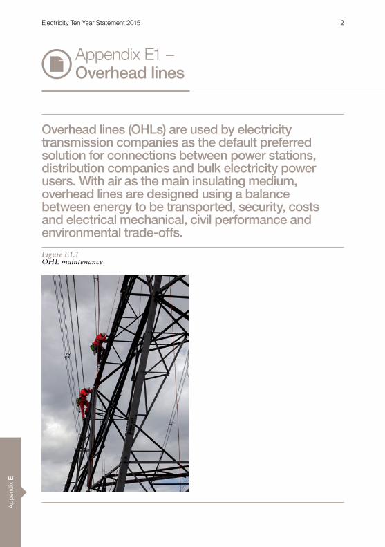
Overhead lines (OHLs) are used by electricity transmission companies as the default preferred solution for connections between power stations, distribution companies and bulk electricity power users. With air as the main insulating medium, overhead lines are designed using a balance between energy to be transported, security, costs and electrical mechanical, civil performance and environmental trade-offs.
Figure E1.1OHL maintenance
Appendix E1 –Overhead lines
Electricity Ten Year Statement 2015 2

Appendix E
An OHL route consists of one or more conductors suspended by towers . The conductors are connected to the towers with insulators, which are traditionally made using cast iron caps encapsulating glass or porcelain . The conductor insulation is provided by air, so OHLs are generally considered to be the most cost-effective method of HVAC transmission .
The towers are designed to support a variety of structural loads . Examples include those imposed by weather events such as wind and ice, along with the additional conductor tensions caused by changes in route direction, line termination or transition to underground cable .
The route design must try to strike a balance between the size and physical presence of structures used . Shorter towers mean shorter span lengths, resulting in more pylons per kilometre . Decisions on tower type and size are based on capability, visual and economic considerations .
In the UK, OHL designs must comply with statutory regulations and standards . These include safety requirements such as ground clearance, electromagnetic fields, earthing, safety signs and preventing unauthorised climbing .
CapabilitiesThe UK introduced OHLs in the 1920s . The current transmission system can carry far greater quantities of electricity through increased voltages and the capacity to carry larger and more advanced conductors . Transmission OHLs in the UK are operated at voltages ranging from 275kV to 400kV . Most routes have two circuits each, with three phases per circuit . Standard conductor sizes range from 24 .7 to 41 .04mm diameter . The maximum rating for a single circuit with a triple conductor bundle is 3820MVA .
Dependencies and impactsOverhead lines are sometimes criticised for spoiling the view . Although existing lines are generally accepted as a necessity with a clear benefit, the construction of any new significant infrastructure is often an emotive issue . The size and impact of transmission voltage OHLs are often of particular concern to some members of the public .
Depending on voltage, phase configuration and conductor bundle, some audible noise is a possibility in close proximity to the line .
The installation of OHLs circuits is potentially less disruptive than the installation of cables, where the continuous linear nature of the construction at ground level can require road closures and diversions for significant periods. However, achieving planning consent for overhead line routes can be more challenging .
Availability HVAC OHL is a mature technology with many suppliers offering reliable components up to 400kV, which is the maximum voltage used in the UK .
Advances in manufacturing technologies and materials mean that designs that were not practically achievable or were uneconomic now have new potential . For new infrastructure, visual amenity can be a key driver in the design . This change has led to a review of more traditional designs and the development of the National Grid T-pylon1 which has been proposed for use on the Hinkley-Seabank project .2
1 RIBA Pylon Design Competition http://www .ribapylondesign .com/2 T-pylon offered for first time http://www.nationalgridt-talk.com/
Electricity Ten Year Statement 2015 3

App
endi
x E
Figure E1.2T-pylon
The traditional insulation materials are glass and porcelain, with ‘cap and pin’ construction linking individual ‘sheds’ to form the required length of insulator unit .
A new generation of composite insulator products made from glass-fibre reinforced polymer rods bonded to silicon rubber housing offers a number of benefits over the traditional design . These include enhanced electrical performance, reduced cost and lighter products, which are easier to handle and take less time to install .
A new generation of high temperature low sag (HTLS) composite cored conductors is being offered to the market for deployment on transmission systems . HTLS offers the possibility of increased ratings using existing structures, thereby avoiding the need to rebuild existing lines . National Grid is reviewing a number of products that may be deployed on the transmission system in the future .
Appendix E1 –Overhead lines
Electricity Ten Year Statement 2015 4
Appendix E
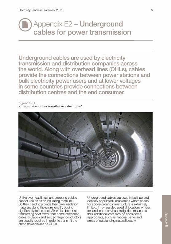
Figure E2.1Transmission cables installed in a 4m tunnel
Unlike overhead lines, underground cables cannot use air as an insulating medium . So they need to provide their own insulation materials along the entire length, adding significantly to the cost. Air is also better at transferring heat away from conductors than cable insulation and soil, so larger conductors are usually required in order to transmit the same power levels as OHLs .
Underground cables are used in built-up and densely populated urban areas where space for above-ground infrastructure is extremely limited . They are also used at locations where, for landscape or visual mitigation measures, their additional cost may be considered appropriate, such as national parks and areas of outstanding natural beauty .
Appendix E2 – Underground cables for power transmission
Underground cables are used by electricity transmission and distribution companies across the world. Along with overhead lines (OHLs), cables provide the connections between power stations and bulk electricity power users and at lower voltages in some countries provide connections between distribution centres and the end consumer.
Electricity Ten Year Statement 2015 5

App
endi
x E
1 HITACHI, The 1,400-MW Kii-Channel HVDC System (online) . (Accessed: 9 September 2015) . Available: http://www.hitachi.com/ICSFiles/afieldfile/2004/06/08/r2001_03_111.pdf
Cables are inherently capacitive and where used in AC systems may require the installation of additional reactive compensation to help control network voltage . The likelihood that additional reactive compensation will be needed for a particular transmission route increases with cable operating voltage, conductor size and circuit length . Additional land space will be required to build compounds for the reactive compensation plant .
Transmission cables are operated at voltages ranging from 132kV to 400kV . Increasing the voltage allows more power to be transmitted but also increases the level of cable insulation required . At 275kV and 400kV most circuits have one or two conductors per circuit . In order to match the ratings of high-capacity OHL circuits, very large cables will be required .
CapabilitiesAt 400kV and 275kV, transmission cables consist of a copper conductor, an insulation layer, a lead sheath and a protective plastic coating .
Transmission cable insulation has developed from self-contained fluid-filled (SCFF) construction with a hollow conductor and paper insulation using pressurised low viscosity oils to extruded plastic insulations . SCFF cables have also used polypropylene paper layers (PPL) that are now being introduced into HVDC cable systems . SCFF technology has been used for DC cable systems too .1
For direct buried underground cables, utilities must obtain easements from the land owners of all the sections of land it crosses .
The power-carrying capability or rating of a transmission cable system depends on the number and size of conductors as well as the installation method and soil resistivity . Larger conductors and higher voltages mean increased ratings . Cables are usually buried at a depth of around 1m in flat agricultural land.
As the number of cables per circuit increases, so does the width of the land required to install them (the swathe) . Cable swathes as wide as 50m may be required for high-capacity 400kV routes .
A 3m allowance for maintenance needs to be added to most corridor widths quoted in supplier information sheets .
At 275kV and 400kV the rating for each circuit can range from 240MVA to 3500MVA based on the size and number of conductors in each trench .
Ratings are calculated on ambient conditions and the maximum safe operating temperature of the conductor . Consequently, ratings are higher in winter than they are in other seasons .
AvailabilityHV cable technology is mature with many manufacturers offering reliable products .
The higher-transmission voltages are more specialised, with proportionally fewer suppliers .
Since the mid-nineties, far fewer SCFF cables have been manufactured, while sales of extruded (XLPE) cable systems have increased significantly.
Dependencies and impactsAlthough cable systems have a lower impact on visual amenity than OHL there are still considerable portions of the cable system above ground, especially at the terminal ends between sections of OHL . Cable systems are generally less prone to environmental issues than OHL because they generate less audible noise .
The installation of underground cable systems is potentially more disruptive than the installation of OHL circuits . This is because the continuous linear nature of the construction at ground level can require road closures and diversions for significant periods. Cable systems do still encounter some environmental issues around the disturbance of land .
Appendix E2 – Underground cables for power transmission
Electricity Ten Year Statement 2015 6
Appendix E
Appendix E3 – Onshore cable installation and landfall
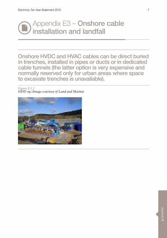
Onshore HVDC and HVAC cables can be direct buried in trenches, installed in pipes or ducts or in dedicated cable tunnels (the latter option is very expensive and normally reserved only for urban areas where space to excavate trenches is unavailable).
Figure E3.1HDD rig (Image courtesy of Land and Marine)
Electricity Ten Year Statement 2015 7
App
endi
x E
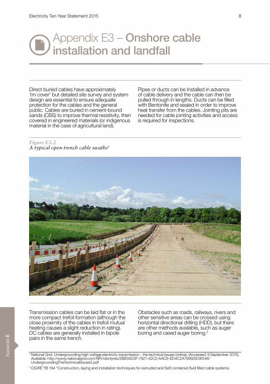
Direct buried cables have approximately 1m cover1 but detailed site survey and system design are essential to ensure adequate protection for the cables and the general public . Cables are buried in cement-bound sands (CBS) to improve thermal resistivity, then covered in engineered materials (or indigenous material in the case of agricultural land) .
Pipes or ducts can be installed in advance of cable delivery and the cable can then be pulled through in lengths. Ducts can be filled with Bentonite and sealed in order to improve heat transfer from the cables . Jointing pits are needed for cable jointing activities and access is required for inspections .
Transmission cables can be laid flat or in the more compact trefoil formation (although the close proximity of the cables in trefoil mutual heating causes a slight reduction in rating) . DC cables are generally installed in bipole pairs in the same trench .
Obstacles such as roads, railways, rivers and other sensitive areas can be crossed using horizontal directional drilling (HDD), but there are other methods available, such as auger boring and cased auger boring .2
Appendix E3 – Onshore cable installation and landfall
Figure E3.2A typical open trench cable swathe1
1 National Grid, Undergrounding high-voltage electricity transmission – the technical issues (online) . (Accessed: 9 September 2015) . Available: http://www .nationalgrid .com/NR/rdonlyres/28B3AD3F-7821-42C2-AAC9-ED4C2A799929/36546/UndergroundingTheTechnicalIssues3 .pdf
2 CIGRÉ TB 194 “Construction, laying and installation techniques for extruded and Self contained fluid filled cable systems.
Electricity Ten Year Statement 2015 8
Appendix E
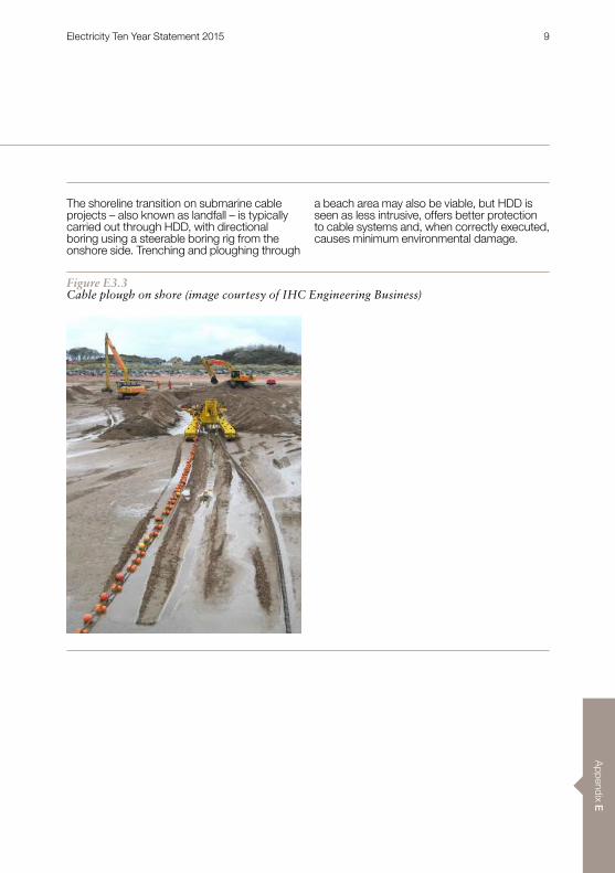
The shoreline transition on submarine cable projects – also known as landfall – is typically carried out through HDD, with directional boring using a steerable boring rig from the onshore side . Trenching and ploughing through
a beach area may also be viable, but HDD is seen as less intrusive, offers better protection to cable systems and, when correctly executed, causes minimum environmental damage .
Figure E3.3Cable plough on shore (image courtesy of IHC Engineering Business)
Electricity Ten Year Statement 2015 9
App
endi
x E
HDD can pass under sea defences and out to sea, with typical horizontal distances of up to 500m and depths of 15m below the seabed . The pilot hole is reamed out to the required size and protector pipes or ducts are used to provide a conduit for the offshore cable . A transition joint pit is constructed onshore and a winch is used to pull the offshore cable through the duct . For the marine works a barge and/or a multi-purpose marine vessel (MPMV) is required, along with a diving team for the various support tasks . Whether it is through a duct prepared by HDD or via a trench, making landfall is a complex operation that requires specialist knowledge .
CapabilitiesOnshore jointing times vary according to cable type, but are usually in the range of one day per joint for XLPE and three to five days for mass impregnated paper insulated cables .
Cable trenches are usually 1-1 .5m deep and 1m wide, with increased width required for jointing bays and construction access, leading to a total swathe of at least 5m for a single cable trench(1) . AC cables also require link boxes for sheath bonding and earthing .
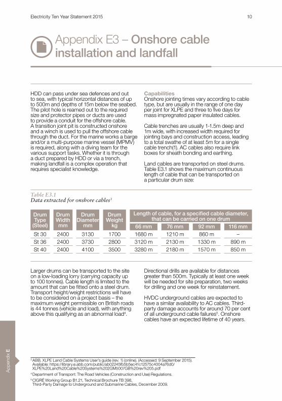
Land cables are transported on steel drums . Table E3 .1 shows the maximum continuous length of cable that can be transported on a particular drum size:
Larger drums can be transported to the site on a low-loading lorry (carrying capacity up to 100 tonnes) . Cable length is limited to the amount that can be fitted onto a steel drum. Transport height/weight restrictions will have to be considered on a project basis – the maximum weight permissible on British roads is 44 tonnes (vehicle and load), with anything above this qualifying as an abnormal load4 .
Directional drills are available for distances greater than 500m . Typically at least one week will be needed for site preparation, two weeks for drilling and one week for reinstatement .
HVDC underground cables are expected to have a similar availability to AC cables . Third-party damage accounts for around 70 per cent of all underground cable failures5 . Onshore cables have an expected lifetime of 40 years .
Table E3.1Data extracted for onshore cables3
Appendix E3 – Onshore cable installation and landfall
Drum Type
(Steel)
Drum Width mm
Drum Diameter
mm
DrumWeight
kg
Length of cable, for a specified cable diameter, that can be carried on one drum
66 mm 76 mm 92 mm 116 mmSt 30 2400 3130 1700 1680 m 1210 m 860 m –St 36 2400 3730 2800 3120 m 2130 m 1330 m 890 mSt 40 2400 4100 3500 3280 m 2180 m 1570 m 850 m
3 ABB, XLPE Land Cable Systems User’s guide (rev . 1) (online) . (Accessed: 9 September 2015) . Available: https://library .e .abb .com/public/ab02245fb5b5ec41c12575c4004a76d0/ XLPE%20Land%20Cable%20Systems%202GM5007GB%20rev%205 .pdf
4 Department of Transport: The Road Vehicles (Construction and Use) Regulations .5 CIGRÉ Working Group B1 .21, Technical Brochure TB 398, Third-Party Damage to Underground and Submarine Cables, December 2009 .
Electricity Ten Year Statement 2015 10

Appendix E
AvailabilityNeary Construction, Durkin & Sons are prime installers of underground HV cable . However, companies including Carillion, United Utilities and National Grid’s Overhead Line and Cable Alliance Partners (AMEC, Babcock and Balfour Beatty) all have extensive experience and capability .
Major directional drilling providers with the experience and capability to manage projects of this nature include AMS No-Dig, Land & Marine, Allen Watson Ltd, DEME , Stockton Drilling (HDD 500m+) and VolkerInfra (parent company Visser & Smit Hanab) .
Belgian-based DEME has group companies including Tideway and GeoSea with experience of landfall operations .
Dependencies and impactsEarly in the project planning process, cable route surveys are required to determine the most feasible cable routing option for the cable system and also to determine first pass cable route lengths for budget purposes . Geotechnical surveys are also required at this time to determine ground conditions along the route so as to establish where more expensive installation methods may be required .
Cable system design is an essential element of any cable project and may have a considerable impact on the final costs. Trenching and drilling through rock are considerably more expensive and time consuming than through softer ground .
Cables can potentially be routed along public highways, avoiding the need for potentially costly wayleaves and access agreements . If cable routes go cross-country (including access for HDD), additional costs to consider include wayleaves, access agreements, trackway costs, farm drain repair, soil reconditioning and crop damage charges .
Generation and offshore transmission licensees may have compulsory acquisition powers and there are legal and compensation costs associated with these powers . There may also be additional licence and project management costs too, such as enabling the crossing of existing services belonging to third parties e .g . roads, railways, and gas, electricity and water services .
When it comes to laying cables their bulk and weight limits the total length between joints . So allowance must be made for the additional cost (and time) for civil engineering works, land access issues and the completion of cable jointing activities . Additional mobilisation costs and per km costs also need to be considered .
Landfall operations are largely dictated by environmental considerations because many areas of shoreline have designations such as Sites of Special Scientific Interest (SSSI), Ramsar sites and Royal Society for Protection of Birds (RSPB) reserves . This may mean that drilling can only take place at certain times . Tidal conditions and weather can also affect the operation of Multi Purpose Marine Vehicles (MPMVs) and diving teams . There is competition for resources, with oil, gas and other construction projects as well as significant market activity overseas.
Landfall and land cable routing often present the most thermally limiting case for cable rating . As such it may be economic to use a larger cable cross-section for the landfall and land route than for a submarine section, to ensure that thermal bottlenecks do not de-rate the entire cable system .
Project examplesnVale of York 2 x 400kV circuits over 6 .5km,
Lower Lea Valley power line undergroundingnWest Byfleet undertrack crossing nGunfleet Sands landfall to Clacton substationnNorNed HVDC project6
6 Thomas Worzyk, Submarine Power Cables: Design, Installation, Repair, Environmental Aspects, Published 2009 ISBN 978-3-642-01270-9 .
Electricity Ten Year Statement 2015 11
App
endi
x E
Appendix E4 – Switchgear
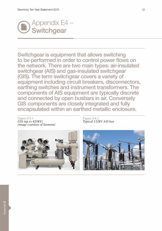
Switchgear is equipment that allows switching to be performed in order to control power flows on the network. There are two main types: air-insulated switchgear (AIS) and gas-insulated switchgear (GIS). The term switchgear covers a variety of equipment including circuit breakers, disconnectors, earthing switches and instrument transformers. The components of AIS equipment are typically discrete and connected by open busbars in air. Conversely GIS components are closely integrated and fully encapsulated within an earthed metallic enclosure.
Figure E4.1GIS (up to 420kV) (image courtesy of Siemens)
Figure E4.2Typical 132kV AIS bay
Electricity Ten Year Statement 2015 12
Appendix E
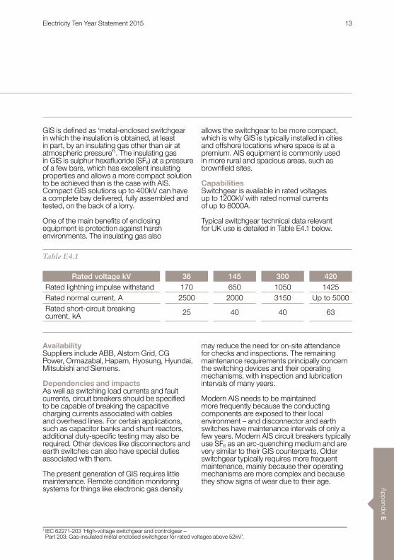
Table E4.1
GIS is defined as ‘metal-enclosed switchgear in which the insulation is obtained, at least in part, by an insulating gas other than air at atmospheric pressure’1 . The insulating gas in GIS is sulphur hexafluoride (SF6) at a pressure of a few bars, which has excellent insulating properties and allows a more compact solution to be achieved than is the case with AIS . Compact GIS solutions up to 400kV can have a complete bay delivered, fully assembled and tested, on the back of a lorry .
One of the main benefits of enclosing equipment is protection against harsh environments . The insulating gas also
allows the switchgear to be more compact, which is why GIS is typically installed in cities and offshore locations where space is at a premium . AIS equipment is commonly used in more rural and spacious areas, such as brownfield sites.
CapabilitiesSwitchgear is available in rated voltages up to 1200kV with rated normal currents of up to 8000A .
Typical switchgear technical data relevant for UK use is detailed in Table E4 .1 below .
AvailabilitySuppliers include ABB, Alstom Grid, CG Power, Ormazabal, Hapam, Hyosung, Hyundai, Mitsubishi and Siemens .
Dependencies and impactsAs well as switching load currents and fault currents, circuit breakers should be specified to be capable of breaking the capacitive charging currents associated with cables and overhead lines . For certain applications, such as capacitor banks and shunt reactors, additional duty-specific testing may also be required . Other devices like disconnectors and earth switches can also have special duties associated with them .
The present generation of GIS requires little maintenance . Remote condition monitoring systems for things like electronic gas density
may reduce the need for on-site attendance for checks and inspections . The remaining maintenance requirements principally concern the switching devices and their operating mechanisms, with inspection and lubrication intervals of many years .
Modern AIS needs to be maintained more frequently because the conducting components are exposed to their local environment – and disconnector and earth switches have maintenance intervals of only a few years . Modern AIS circuit breakers typically use SF6 as an arc-quenching medium and are very similar to their GIS counterparts . Older switchgear typically requires more frequent maintenance, mainly because their operating mechanisms are more complex and because they show signs of wear due to their age .
Rated voltage kV 36 145 300 420Rated lightning impulse withstand 170 650 1050 1425Rated normal current, A 2500 2000 3150 Up to 5000Rated short-circuit breaking current, kA 25 40 40 63
1 IEC 62271-203 ‘High-voltage switchgear and controlgear – Part 203: Gas-insulated metal enclosed switchgear for rated voltages above 52kV’ .
Electricity Ten Year Statement 2015 13
App
endi
x E
New AIS switchgear that combines the functions of several separate devices is starting to become available at transmission levels, along with other hybrid switchgear . By reducing the physical footprint of AIS substations, these devices reduce the need to install costly GIS where space is at a premium .
Maintenance and repair of equipment filled with SF6 may require the gas to be removed by suitably trained and qualified personnel.
The gas has a high global warming potential and should not be released deliberately to the atmosphere . Exposure to high temperatures (such as arcing during circuit breaker operation or as a result of an internal fault) can cause decomposed gas to yield highly reactive and toxic decomposition products – guidance on SF6 gas handling is given in .2
Data on GIS service experience has been published by CIGRÉ .3, 4
Appendix E4 – Switchgear
2 IEC/TR 62271-303 ‘High-voltage switchgear and controlgear – Part 303: Use and handling of sulphur hexafluoride’.3 CIGRÉ WG 23 .02, ‘Report on the second international survey on high voltage gas insulated substations service experience’, Ref . 150, February 2000 .
4 CIGRÉ WG A3 .06 ‘Final Report of the 2004 – 2007 International Enquiry on Reliability of High Voltage Equipment’, Ref . 509, 513 and 514, 21 October 2012 .
Electricity Ten Year Statement 2015 14
Appendix E
Appendix E5 – Transformers
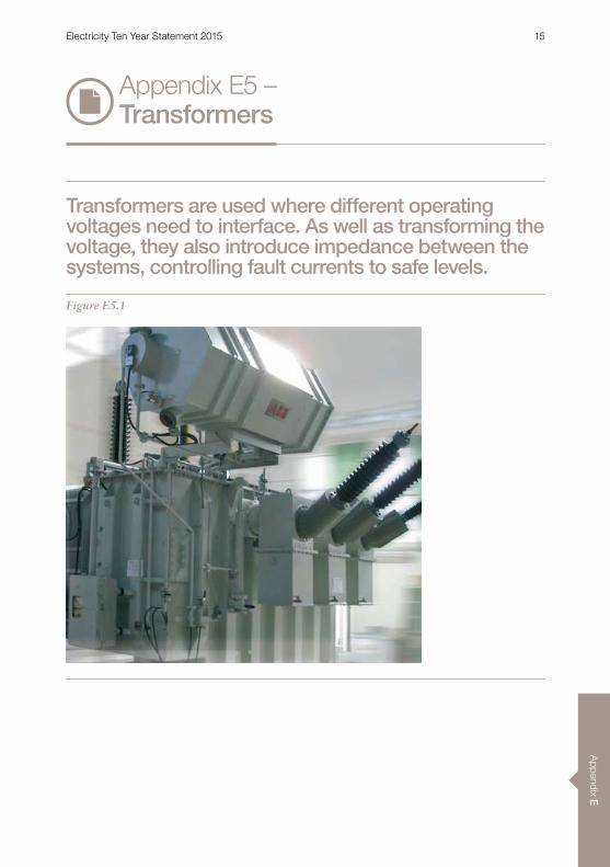
Transformers are used where different operating voltages need to interface. As well as transforming the voltage, they also introduce impedance between the systems, controlling fault currents to safe levels.
Figure E5.1
Electricity Ten Year Statement 2015 15
App
endi
x E
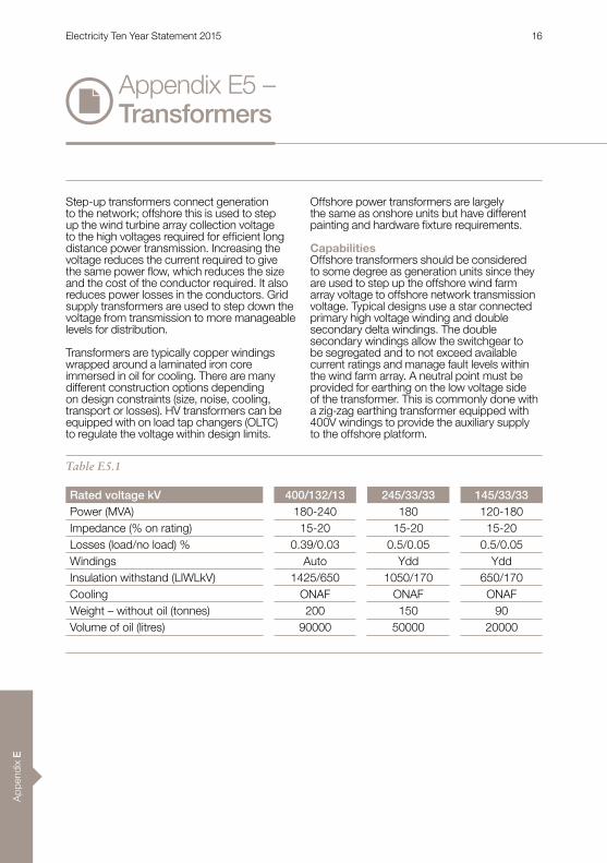
Step-up transformers connect generation to the network; offshore this is used to step up the wind turbine array collection voltage to the high voltages required for efficient long distance power transmission . Increasing the voltage reduces the current required to give the same power flow, which reduces the size and the cost of the conductor required . It also reduces power losses in the conductors . Grid supply transformers are used to step down the voltage from transmission to more manageable levels for distribution .
Transformers are typically copper windings wrapped around a laminated iron core immersed in oil for cooling . There are many different construction options depending on design constraints (size, noise, cooling, transport or losses) . HV transformers can be equipped with on load tap changers (OLTC) to regulate the voltage within design limits .
Offshore power transformers are largely the same as onshore units but have different painting and hardware fixture requirements.
CapabilitiesOffshore transformers should be considered to some degree as generation units since they are used to step up the offshore wind farm array voltage to offshore network transmission voltage . Typical designs use a star connected primary high voltage winding and double secondary delta windings . The double secondary windings allow the switchgear to be segregated and to not exceed available current ratings and manage fault levels within the wind farm array . A neutral point must be provided for earthing on the low voltage side of the transformer . This is commonly done with a zig-zag earthing transformer equipped with 400V windings to provide the auxiliary supply to the offshore platform .
Rated voltage kV 400/132/13 245/33/33 145/33/33Power (MVA) 180-240 180 120-180Impedance (% on rating) 15-20 15-20 15-20Losses (load/no load) % 0 .39/0 .03 0 .5/0 .05 0 .5/0 .05Windings Auto Ydd YddInsulation withstand (LIWLkV) 1425/650 1050/170 650/170Cooling ONAF ONAF ONAFWeight – without oil (tonnes) 200 150 90Volume of oil (litres) 90000 50000 20000
Table E5.1
Appendix E5 – Transformers
Electricity Ten Year Statement 2015 16
Appendix E
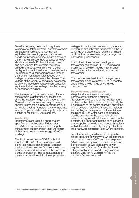
Transformers may be two winding, three winding or autotransformers . Autotransformers are usually smaller and lighter than an equivalent two winding power transformer, but do not provide electrical isolation between the primary and secondary voltages or lower short circuit levels . Both autotransformers and two winding transformers may have an additional tertiary winding with a delta configuration, which reduces triplen harmonics (multiples of third harmonic) passing through the transformer . It also helps reduce any voltage unbalance between the phases . The voltage of the tertiary winding may be chosen to allow connection of reactive compensation equipment at a lower voltage than the primary or secondary windings .
The life expectancy of onshore and offshore transformers is determined by the loading, since the insulation is generally paper and oil . Generator transformers are likely to have a shorter lifetime than supply transformers due to heavier loading . Generator transformers last around 25 years, while many supply units have been in service for 40 years or more .
AvailabilityTransformers are reliable if appropriately specified and looked after. Failure rates of 0 .25% are not unreasonable for supply transformers but generation units will exhibit higher rates due to heavier usage (80-90% loading) .
This is discussed in the CIGRÉ technical brochure TB 2481 . Offshore units should be no less reliable than onshore, although the long cables used in offshore circuits may induce stress and resonance in the transformer during energisation . The compact nature of the substation will result in close-up, very fast
voltages to the transformer winding generated by vacuum circuit breaker transients on the LV windings and disconnector switching . These could in time cause overvoltage damage due to part winding resonances .
In addition to the core and windings, a transformer can have an OLTC, cooling and bushings, all of which require maintenance, so it’s important to monitor all parts of the transformer .
The procurement lead time for a large power transformer is approximately 18 to 24 months and there is a wide range of worldwide manufacturers .
Dependencies and impactsWeight and space are critical design parameters for offshore platforms . Transformers will be one of the heaviest items of plant on the platform and would normally be placed close to the centre of gravity, above the pile or jacket, for stability . Associated radiators and cooling fans are placed on the outside of the platform . Sea water-based cooling may also be preferred to the conventional oil/air based cooling . As with all the equipment on the platform, it is important that the paint is marine grade, applied carefully and inspected regularly, with defects taken care of promptly . Stainless steel hardware should be used where possible .
Transformer ratings will need to be specified for the apparent power (MVA), which comprises both the real power (MW) and reactive power (MVAr) provided by wind turbines and reactive compensation as well as reactive power requirements of cables . Standardisation of ratings, configurations and voltages across offshore wind farms would minimise the number of spares required .
1 Guide on economics of transformer management: CIGRÉ technical brochure 248 .
Electricity Ten Year Statement 2015 17

App
endi
x E
Additional informationn IEC 60076 – Power Transformers .
n IEC 60214 – On load tap changers .
n International Survey on failure in service of large power transformers . CIGRÉ ELECTRA 88_1, 1978.
n Transformer reliability surveys, CIGRÉ session paper A2-114, 2006 .
n N . Andersen, J . Marcussen, E .Jacobsen, S . B . Nielsen, Experience gained by a major transformer failure at the offshore platform of the Nysted Offshore Wind Farm, presented at 2008 Wind Integration Conference in Madrid, Spain .
Transformer HV terminals can be connected directly to the HV gas insulated switchgear . This allows efficient use of space on the offshore platform . Platforms with more than one transformer can have the wind farm switchgear configured with normally open bus section breakers . This allows one of the transformers to be switched out for maintenance or following a fault while the wind farm can remain connected to the grid within the ratings of the transformers still in service . Transformers may be temporarily overloaded, although this decreases their lifetime expectancy .
Transformers pose the two greatest environmental risks on the platform in the event of a major failure; namely oil spillage and transformer fire. Oil bunds, separation and dump tanks will be required . Fire
suppression or control should be investigated . Synthetic oils are much less combustible but are more expensive than mineral oils and need a bigger transformer due to lower dielectric strength . Research has been completed on the use of synthetic esters for 400kV applications and the first synthetic ester filled 400kV transformer has been manufactured and successfully tested .
The logistics around a transformer failure and replacement must be considered, particularly the removal from the platform . An incident offshore will be very costly depending on the availability of a spare and of a repair vessel and suitable weather . Long lead times could mean extended outages while a replacement is sourced, so a cost benefit analysis of redundancy or overload options is recommended .
Appendix E5 – Transformers
Auto transformer(star/star)
Two windingtransformer(star/delta)
Three windingtransformer
(star/delta/delta)
Figure E5.2
Electricity Ten Year Statement 2015 18

Appendix E
Appendix E6 – Shunt reactors
Figure E6.1 Air core reactors (blue), (image courtesy of Enspec Power)
Shunt reactors are used to compensate for the capacitive reactive power in AC transmission networks, regulating the network voltage. HVAC cables have a high capacitance and shunt reactors are used at the onshore interface point; at the offshore substation platform and potentially at intermediate points along the cable length (such as at the shore landing point).
Electricity Ten Year Statement 2015 19
App
endi
x E
Appendix E6 – Shunt reactors
Reactors have either an air core or gapped iron core design . Iron core reactors are commonly immersed in a tank of oil with a similar construction to power transformers, but the gapped iron core makes it harder for a higher magnetising current to flow. Air core reactors (ACR) are larger but simpler than iron core reactors, and need less maintenance . As they do not have non-linear iron cores, they are not subject to core saturation effects . Shunt reactors may be connected to tertiary windings on power transformers or connected to the HV busbar via switchgear for operational switching and protection .
CapabilitiesGenerally, ACRs are cheaper but larger, so where space is limited and high ratings are required, oil immersed units dominate . ACRs are commonly available up to 72kV and 100MVAr . Higher voltages and ratings are possible but generally regarded as special designs . Oil immersed iron core reactors are available up to 800kV and 250MVAr .
AvailabilityThere is little data on reactor reliability, however oil immersed units are comparable to transformers (without tap changers) . Air cored units will have a lower availability due to the large surface area, the impact of wildlife – such as nesting birds – and exposure to the environment . Air cored units need little maintenance apart from visual inspection, while oil immersed unit maintenance will be similar to that of transformers .
Lead times of shunt reactors range from 12 to 24 months and there are many manufacturers worldwide .
Dependencies and impactsA drawback with ACRs is that the magnetic field extends beyond the reactor so they need specialised installation . Metallic loops in adjacent constructions must be avoided where circulating currents could flow, which could be problematic offshore . Iron core oil immersed reactors in a tank do not have significant magnetic fields extending beyond the tank and the reactor is well protected from the environment, making them better suited for the offshore environment . Reactors can be used with AC offshore transmission networks to supply the reactive demands of the offshore power park cables and the three core offshore transmission cables . Note that harmonics can raise the temperature in the ACR: excessive temperature can cause overheating, ageing and possibly fire.
Circuit breakers need to be suitably rated and tested to switch reactors, in particular the transient recovery voltage (TRV) established during opening .
Additional informationn IEC 60076-6 Power transformers –
Part 6: Reactors – Edition 1 .0 (2007) .
Electricity Ten Year Statement 2015 20
Appendix E
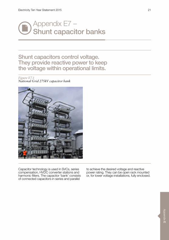
Capacitor technology is used in SVCs, series compensation, HVDC converter stations and harmonic filters. The capacitor ‘bank’ consists of connected capacitors in series and parallel
to achieve the desired voltage and reactive power rating . They can be open rack mounted or, for lower voltage installations, fully enclosed .
Appendix E7 – Shunt capacitor banks
Shunt capacitors control voltage. They provide reactive power to keep the voltage within operational limits.
Figure E7.1National Grid 275kV capacitor bank
Electricity Ten Year Statement 2015 21
App
endi
x E
CapabilitiesShunt capacitor banks can take several forms:nFixed capacitors that are permanently
connected to the power network (usually at LV, i .e . 11kV)
nMechanically switched capacitors (MSC) that use dedicated circuit breakers to connect them to the power network
nThyristor switched capacitors (TSC) that use power electronic valves to connect them to the power network (i .e . SVC) .
Power system studies establish which type of reactive compensation is required to meet system needs . The optimised solution must be capable of taking into consideration any operational strategy, available footprint and future developments .
Static capacitor banks are used for steady state voltage control and can be part of a substation voltage control scheme, coordinated with other voltage control devices such as transformer tap changer control and shunt reactors .
An automatic response to faults and network oscillations requires a faster acting device such as an SVC (Appendix E8) or STATCOM (Appendix E9), which is capable of providing dynamic variable response, rather than switching lumps of capacitance in and out of service . These technologies are more expensive and their cooling and auxiliary systems need more management (see SVCs and STATCOM sections) .
MSCs connected at 132kV and below may have individual banks (e .g . 3 x 45MVAr), each capable of being switched in and out of service by their own circuit breaker . They may also be ganged in parallel via a common circuit breaker that is capable of switching all of the banks in and out of service together .
AvailabilityThe rating of a capacitor bank is determined by the system requirement . There are units with ratings up to 765kV and 600MVAr deployed around the world .
Dependencies and impactsThe switching of reactive power introduces voltage step changes and power quality issues on the connected power network, which need to be taken into consideration when locating and designing an MSC installation .
The circuit breakers for the MSC may require a point-on-wave (POW) control facility to ensure that each pole of the circuit breaker closes as near to the zero voltage crossing as possible to reduce the amplitude of any switching transients generated . Other methods include a damping network (DN) or filter on the MSC circuit (MSC-DN) to reduce the amplitude of the switching transients .
MSCs for connection on to the transmission system at 275kV or above typically comprise single banks of capacitance that are switched in and out of service by individual circuit breakers (i .e . the individual banks are not ganged together) . However, a damping network or POW facilities may be needed on some transmission systems .
Capacitor banks are switched as lumped units with a circuit breaker. If finer gradation is required, multiple smaller banks, with more circuit breakers, are needed . The overall size of the capacitor banks is limited by the circuit breakers’ ability to switch capacitive current, and is determined by the power network’s requirement for reactive power at a given location and its ability to accept reactive power .
These are available from many worldwide manufacturers .
Appendix E7 – Shunt capacitor banks
Additional informationn Electra No . 195, April 2001, CIGRÉ WG 36 .05/Cired 2 CC02, Thomas E . Grebe,
Capacitor Switching and its impact on power quality .
Electricity Ten Year Statement 2015 22
Appendix E
Appendix E8 – Static VAR compensators (SVC)
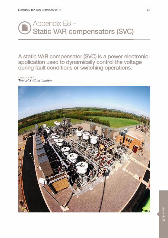
A static VAR compensator (SVC) is a power electronic application used to dynamically control the voltage during fault conditions or switching operations.
Figure E8.1Typical SVC installation
Electricity Ten Year Statement 2015 23

App
endi
x E
The SVC is designed to preserve voltage stability by rapidly supplying reactive power to support the voltage during the transient period. It is part of the flexible AC transmission system (FACTS) genre of equipment . Essentially, SVCs and static compensators (STATCOMs) deliver a similar function using different power electronic technologies and methods . SVCs also provide power oscillation damping where instabilities could arise between different parts of a power system .
The SVC function provides variable inductive and capacitive reactive power using a combination of thyristor controlled reactors (TCR), thyristor switched reactors (TSR) and thyristor switched capacitors (TSC) . These
are connected to the AC network using a compensator transformer or via the transformer tertiary winding .
CapabilitiesAn SVC can provide a fast, continuously variable reactive power response using the TCRs, with the coarser reactive control provided by the TSRs and TSCs . The reactive power MVAr output of the SVC may be controlled directly or be configured to automatically control the voltage by changing its MVAr output accordingly . As the SVC uses AC components to provide reactive power, the MVAr production reduces in proportion to the square of the voltage .
A suitably rated SVC can provide fault ride through capability at the interface point of the offshore transmission network and the onshore transmission system, as required by the System Operator/Transmission Owner Code (STC) .
SVCs can be used for AC connections or with a current source converter (CSC) HVDC-based solution . Voltage source converter (VSC) HVDC solutions can inherently control MVAr output, so do not necessarily need an SVC .
Figure E8.2Typical SVC configuration
TCR TSC Filter
Earthing Transformer
Compensator
Transformer
Appendix E8 – Static VAR compensators
Electricity Ten Year Statement 2015 24

Appendix E
SVCs are made up to 500kV and 720MVAr; and they have been in operation for many years at higher ratings and voltages than STATCOMs . SVCs tend to be cheaper than STATCOMs on a like-for-like basis, but have a larger footprint .
Dependencies and impactsThe TCRs produce harmonics that normally require fifth and seventh harmonic filters, and star-delta winding transformers to block third and ninth harmonics . Six-pulse SVCs are typical, but where there’s space and concern about harmonic performance, twelve pulse SVCs can be considered .
A step-up transformer is usually required to couple the SVC to the required bus section . These are specialised transformers with low voltage secondary windings (e .g . 10kV) and the capability to handle the reactive power flow and block triplen harmonics . If a transformer fails, the SVC will be out of service until the transformer is repaired or replaced .
The fast dynamic response of the SVC is provided by thyristor valves that are water cooled, air insulated and designed for indoor use . The reactors and capacitors are usually housed outdoors unless there are noise considerations .
Where dynamic voltage control is being deployed in close electrical proximity to other power electronic control systems (such as wind turbines, generators and HVDC) it is important to ensure that interaction between the control systems is identified at the design stage and avoided .
SVC reliability is heavily dependent on the availability of auxiliary systems (cooling, LVAC and power supply) and spare parts provision . Auxiliary systems are needed for the power electronic converter cooling and any building air conditioning systems . These systems may be duplicated to help improve overall availability .
The typical SVC design lifetime is 20 to 30 years . Cooling systems and control and protection may need to be replaced earlier depending on condition .
Project examplesnNysted Offshore Windfarm: -65/+80MVAr,
132kV SVC supplied and installed onshore (at Radsted) by Siemens to comply with Grid Code requirements .
nAlleghny Power, Black Oak: 500MVAr, 500kV SVC supplied and installed by ABB to improve transmission line reliability by controlling line voltage .
nNational Grid, UK: 60MVAr re-locatable SVCs supplied by ABB and Alstom Grid .
nBrown switching Station near Brownwood, Texas: 2 x -265/+300MVAr, 345kV supplied by Mitsubishi Electric to support the transmission of renewable energy from generation sites in west Texas .
Additional informationn B4_106 Viklandet & Tunnsjodal SVCs –
Design, project execution and operating experience . M . Meisingset et al . CIGRÉ, Paris 2010
n B4_201 Operational experiences of SVCs in Australia, A . Janke, J . Mouatt, CIGRÉ, Paris 2008 .
n CIGRÉ technical brochure TB025 – Static Var Compensators, TF 38 .01 .02, 1986 .
n CIGRÉ technical brochure TB093 – Guidelines for testing of thyristor valves for static VAR compensators . WG14 .01 .02, 1995 .
Electricity Ten Year Statement 2015 25
App
endi
x E
Appendix E9 – Static compensator (STATCOM)
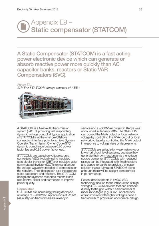
A Static Compensator (STATCOM) is a fast acting power electronic device which can generate or absorb reactive power more quickly than AC capacitor banks, reactors or Static VAR Compensators (SVC).
A STATCOM is a flexible AC transmission system (FACTS) providing fast responding dynamic voltage control . A typical application of STATCOM is at the onshore/offshore connection interface point to achieve System Operator/Transmission Owner Code (STC) dynamic compliance between 0 .95 power factor lag and 0 .95 power factor lead .
STATCOMs are based on voltage source converters (VSC), typically using insulated gate bipolar transistor (IGBTs) or insulated gate commutated thyristor (IGCTs) to manufacture the voltage waveform needed to compensation the network . Their design can also incorporate static capacitors and reactors . The STATCOM design and dynamic response means it can also control flicker and harmonics to improve power quality .
CapabilitiesSTATCOMs are increasingly being deployed at ratings of ±200MVAr . Applications at 220kV (via a step-up transformer) are already in
service and a ±300MVAr project in Kenya was announced in January 2015 . The STATCOM can control the MVAr output or local network voltage by controlling the MVAr output or local network voltage by controlling the MVAr output in response to voltage rises or depressions .
STATCOMs are suitable for weak networks or low short circuit level systems, because they generate their own response via the voltage source converter . STATCOMs with reduced ratings can be integrated with fixed reactors and capacitor banks to provide a cheaper solution than a fully rated STATCOM alone, although there will be a slight compromise in performance .
Recent developments in HVDC VSC technology has led to the introduction of high voltage STATCOM devices that can connect directly to the grid without a transformer at medium voltages (e .g . 33kV) . Applications at transmission with higher voltages need a transformer to provide an economical design .
Figure E9.132MVAr STATCOM (image courtesy of ABB )
Electricity Ten Year Statement 2015 26
Appendix E
Dependencies and impactsSTATCOMs are designed to be installed in a building or enclosure, not outside . Usually, a step-up transformer couples the STATCOM to the required bus voltage, especially at transmission voltages .
STATCOMs can be combined with mechanically switched capacitor (MSC) banks, mechanically switched reactors (MSR) and thyristor switched capacitor (TSC) banks into a cost-effective and technically compliant scheme . However, the equipment needs to be adequately rated and designed for continuous capacitor bank and reactor switching for the solution to meet STC and Grid Code dynamic and harmonic requirements .
Where dynamic voltage control is being deployed in close electrical proximity to other power electronic control systems (such as wind turbines, generators and HVDC) it is important to ensure that interaction between the control systems is identified at the design stage and avoided .
Auxiliary systems are essential for the power electronic converter cooling and any building air conditioning systems . These systems may be duplicated to help improve overall reliability .
The typical design lifetime is 20 to 30 years . Cooling systems, control and protection may need to be replaced earlier depending on condition . STATCOMS should be designed to have an availability rate of above 98% . Reliability is dependent on the auxiliary system (cooling, LVAC and power supply) and availability of spare components .
This can often be increased by adding redundant modules within the STATCOM and keeping replacement parts on site .
Project ExamplesnGreater Gabbard Windfarm +/- 50MVAr
SVC PLUS with MSC and MSR, supplied by Siemens .
nDong Guang, China 220kV connection, +/-200MVAr supplied and installed by Rongxin Power Electronic .
nHolly STATCOM comprises a +110/-80MVAr VSC, together with capacitor banks and filters to give a total range of 80MVAr inductive to 200MVAr capacitive . Supplied and installed by ABB .
nSDG&E Talegat: ±100MVAr 138kV STATCOM, supplied and installed by Mitsubishi Electric
Additional informationn Guillaume de Préville, Wind farm
integration in large power systems; Dimensioning parameters of D-Statcom type solutions to meet grid code requirements . CIGRÉ 2008 Session paper B4_305
n Grid compliant AC connection of large offshore wind farms using a Statcom, S . Chondrogiannis et al . EWEC 2007
n CIGRÉ Technical Brochure – TB144 Static Synchronous compensator (STATCOM), CIGRÉ WG14 .19, 1999 .
Electricity Ten Year Statement 2015 27

App
endi
x E
Appendix E10 – Series compensation
Series compensation (SC) is widely used in many transmission systems around the world, typically in long transmission lines where increased power flow, increased system stability or power oscillation damping (POD) is required.
Figure E10.1Series compensation installation (image courtesy of Nokian Capacitors)
Sometimes, series compensation can be an alternative to building new or additional transmission lines, but before it is installed network complexities must be analysed and mitigated .
SC operates at system voltage, in series with the existing transmission lines; so to provide an economic solution, the equipment is installed on insulated platforms above ground .
Electricity Ten Year Statement 2015 28

Appendix E
There are two main types of series compensation:nFixed series capacitors (FSC)nThyristor controlled series capacitors (TCSC) .
A third design developed by Siemens is called thyristor protected series capacitors (TPSC) .The FSC is the simplest and most widely used design as it has a fixed capacitance that is switched in and out using a bypass switch . The load current through the transmission line directly “drives” the MVAr output from the capacitor and makes the compensation “self-regulating” .
The TCSC installation is more adaptable . It can vary the percentage of compensation by using a thyristor controlled reactor (TCR) and has the potential to manage or control power system conditions such as power oscillations and sub-synchronous resonance (SSR) . In some designs, it may also allow the capacitors to be returned to service faster than FSCs after fault recovery . One drawback of the TCSC is that because the valves are always operational, they must be continuously cooled by a fluid filled cooling system .
The TPSC is similar to a FSC in that it has only a fixed value of capacitance, but using thyristor valves and a damping circuit may allow the capacitors to be returned to service faster than FSCs after fault recovery . As the valves are operational only during fault conditions (compared to those of a TSCS, which are in continuous operation) there is no need for a fluid cooling system.
CapabilitiesIn a transmission system, the maximum active power that can be transferred over a power line is inversely proportional to the series reactance of the line . So by compensating the series reactance using a series capacitor, the circuit appears to be electrically shorter than it really is and a higher active power transfer can be achieved . Since the series capacitor is self-regulated – which means that its output is directly (without control) proportional to the line current itself – it will also partly balance the voltage drop caused by the transfer reactance . Consequently, the voltage stability of the transmission system is raised .
Figure E10.2Simplified model of transmission system with series compensation
Electricity Ten Year Statement 2015 29

App
endi
x E
Installing the series capacitors on the network can help provide:nIncreased transmission capacitynIncreased dynamic stability of power
transmission systemsnImproved voltage regulation and reactive
power balancenImproved load sharing between parallel lines .
Thyristor control further enhances the capability of series compensation including:nSmooth control of power flownImproved capacitor bank protectionnMitigation of SSRnElectromechanical power oscillation
damping .
AvailabilityThe technology is comparable to shunt capacitors and SVCs . However, the complexity of their operation means significant modelling and testing are required .
There are a number of suppliers, with design and manufacturing lead times of around 18-24 months .
Dependencies and impactsThe first installations of SC have been commissioned on the National Grid and SP Transmission’s transmission networks in 2015 . Several challenges have been identified with the installation of the SC on the GB power network:nImpact on existing protection and controlnTransient recovery voltage studynInteraction with other control systems .
Concerns about SSR should be carefully considered to ensure that the advantages of SC are maintained . Complex network analysis is required to understand the effects of introducing series capacitors into the network and to avoid potential hazards to generators .SC can affect protection equipment of adjacent circuits under fault conditions so settings must be reviewed and changed to accommodate the SC .
Project examplesn2008 North South Interconnection III,
BRAZIL (FSC) – To avoid losses and voltage stability
problems, five fixed series capacitors (FSCs) 130–343MVAr were installed at five substations within 14 months . The degree of compensation across the circuits ranged between 51–70%
nThe Isovaara 400kV SC: increased power transmission capacity between Sweden and Finland (TCSC)
– A 515MVAr series capacitor was installed in the 400kV Swedish National Grid . This installation was designed to increase the power transmission capacity of an existing power corridor between Sweden and Finland by increasing voltage stability at steady state as well as transient grid conditions . Series compensation allows the existing power corridor to operate closer to its thermal limit without jeopardizing its power transmission stability in conjunction with possible system faults .
Appendix E10 – Series compensation
Additional informationn CIGRÉ TB123 – Thyristor Controlled Series
Compensation, WG 14 .18, Dec 1997 .
n CIGRÉ TB411 – Protection, Control and Monitoring of Series Compensated Networks, WG B510, Apr 2010 .
Electricity Ten Year Statement 2015 30
Appendix E
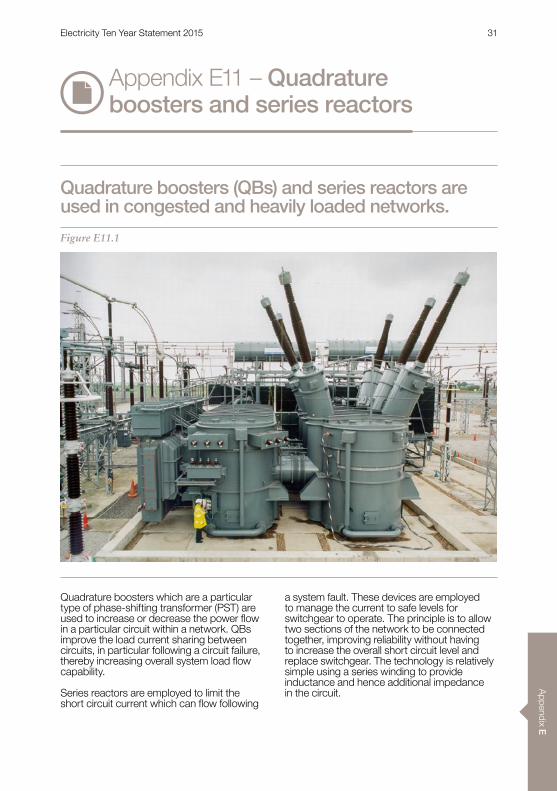
Quadrature boosters which are a particular type of phase-shifting transformer (PST) are used to increase or decrease the power flow in a particular circuit within a network . QBs improve the load current sharing between circuits, in particular following a circuit failure, thereby increasing overall system load flow capability .
Series reactors are employed to limit the short circuit current which can flow following
a system fault . These devices are employed to manage the current to safe levels for switchgear to operate . The principle is to allow two sections of the network to be connected together, improving reliability without having to increase the overall short circuit level and replace switchgear . The technology is relatively simple using a series winding to provide inductance and hence additional impedance in the circuit .
Appendix E11 – Quadrature boosters and series reactors
Quadrature boosters (QBs) and series reactors are used in congested and heavily loaded networks.
Figure E11.1
Electricity Ten Year Statement 2015 31
App
endi
x E
Appendix E11 – Quadrature boosters and series reactors
A QB consists of a shunt (exciter) and a series transformer configured such that two phases inject a voltage into the third phase, thereby changing the load current . A tap changer controls the direction and magnitude of injected voltage, which is used to either increase or reduce the current flow and the real power transmitted .
Both equipment types utilise similar technology to power transformers and require essentially the same maintenance and asset management .
CapabilitiesLike transformers, QBs and series reactors are specifically designed for the networks they operate in . The highest capability QBs employed on the transmission system at 400kV have a throughput rating of 2750MVA to match the circuit and are amongst the largest in use worldwide . Series reactor ratings are matched to the circuit and can exceed 3000MVA . The higher rated units are split into three single phase components to facilitate transport .
AvailabilityThe technology is comparable to normal power transformers . However, to meet system requirements these are very large devices (the heaviest items of equipment on the system) representing significant testing and transport challenges . There are a number of suppliers, with design and manufacturing lead times of around 24 months .
Dependencies and impactsBoth applications are fundamentally based on transformer technology, and are susceptible to the same issues, including sensitivity to voltage transients, and a requirement for site power for forced cooling at high loads . Both need to be rated for the circuit or busbar duty . QBs and series reactors can cause high voltage transients during switching, which need to be controlled with surge arresters; and the associated circuit breakers need to be suitably rated and tested to switch series reactors .
The electrical losses caused by QBs and series reactors are kept to an economic minimum using a whole life cost formula . The best available technology is used to reduce the no-load loss of QBs; and although size is limited by the requirement to transport the units to site, efficiency is still very high. Series reactors are particularly efficient because they only consume electricity when carrying load and high loads are only experienced under system fault conditions .
QBs and series reactors can cause significant reactive power flows when they are being used as intended when other parts of the transmission system have failed . These need to be fully analysed at the design stage .
Additional informationn IEC 60076-6 Power transformers –
Part 6: Reactors
n IEC 62032 Guide for the Application, Specification and Testing of Phase- Shifting Transformers
Electricity Ten Year Statement 2015 32
Appendix E
Appendix E12 – Submarine three core cables
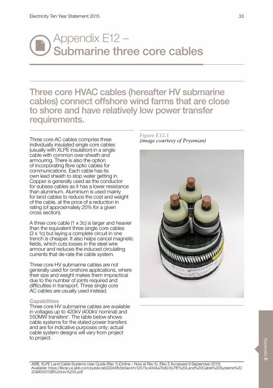
Three core AC cables comprise three individually insulated single core cables (usually with XLPE insulation) in a single cable with common over-sheath and armouring . There is also the option of incorporating fibre optic cables for communications . Each cable has its own lead sheath to stop water getting in . Copper is generally used as the conductor for subsea cables as it has a lower resistance than aluminium . Aluminium is used mainly for land cables to reduce the cost and weight of the cable, at the price of a reduction in rating (of approximately 20% for a given cross section) .
A three core cable (1 x 3c) is larger and heavier than the equivalent three single core cables (3 x 1c) but laying a complete circuit in one trench is cheaper . It also helps cancel magnetic fields, which cuts losses in the steel wire armour and reduces the induced circulating currents that de-rate the cable system .
Three core HV submarine cables are not generally used for onshore applications, where their size and weight makes them impractical due to the number of joints required and difficulties in transport. Three single core AC cables are usually used instead .
CapabilitiesThree core HV submarine cables are available in voltages up to 420kV (400kV nominal) and 550MW transfers1 . The table below shows cable systems for the stated power transfers and are for indicative purposes only; actual cable system designs will vary from project to project .
Three core HVAC cables (hereafter HV submarine cables) connect offshore wind farms that are close to shore and have relatively low power transfer requirements.
Figure E12.1(image courtesy of Prysmian)
1 ABB, XLPE Land Cable Systems User Guide (Rev 1) (Online – Now at Rev 5) . (Rev 5 Accessed 9 September 2015) Available: https://library .e .abb .com/public/ab02245fb5b5ec41c12575c4004a76d0/XLPE%20Land%20Cable%20Systems%202GM5007GB%20rev%205 .pdf
Electricity Ten Year Statement 2015 33

App
endi
x E
Capacity(MW)
Voltage(kV)
Number of cables required
Cross(mm²)
Weight(kg/m)
Diameter(mm)
100 132 1 300 48 167150 132 1 500 58 176
200132 1 1000 85 206220 1 300 67 204
300132 2 500 2x58 2x176220 1 800 95 234
400132 2 1000 2x85 2x206220 2 300 2x67 2x204
500132 3 630 3x65 3x185220 2 500 2x81 2x219
600132 3 1000 3x85 3x206220 2 800 2x95 2x234
800132 4 1000 4x85 4x206220 3 630 3x87 3x224
1000132 5 1000 5x85 5x206220 3 1000 3x10⁴ 3x241
Table E12.1
The following assumptions were made for the above table: sea soil temperature 15˚C, burial 1 .0m, thermal resistivity 1kW/m, copper conductor, steel wire armour . The capacities data has been taken from references 1 and 2 . 132kV and 220kV are the nominal voltage ratings . These cables can operate up to 145kV and 245kV respectively, allowing slightly increased capacities on the same cables .
AvailabilitySupply and installation times are in the region of one to two years . Suppliers include ABB, Prysmian, Nexans and NKT .
Dependencies and impactsThree core HV submarine cables are intended for AC system use and need reactive compensation equipment, in the form of shunt reactors, at one or both ends of the cable . As the cable length increases, so the amount of capacitive charging current increases and the amount of active power that can be transmitted decreases . Beyond a certain threshold distance, HVDC links should be considered . The following graph shows how for AC cable transmission the maximum real power transferred reduces dramatically for longer cable lengths .
Appendix E12 – Submarine three core cables
2 ABB, XLPE Submarine Cable Systems, Attachment to XLPE Cable Systems User Guide . (Rev 1) (Online – Now at Rev 5) . (Rev 5 Accessed 9 September 2015) Available: http://new .abb .com/docs/default-source/ewea-doc/xlpe-submarine-cable-systems-2gm5007 .pdf?sfvrsn=2
Electricity Ten Year Statement 2015 34
Appendix E
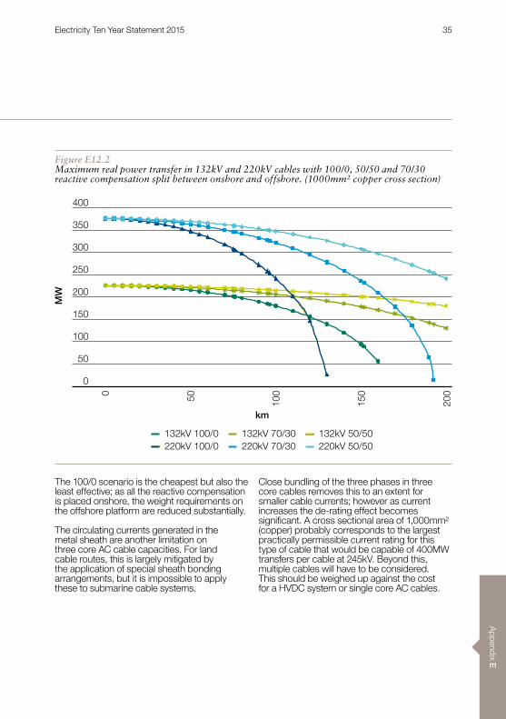
Figure E12.2Maximum real power transfer in 132kV and 220kV cables with 100/0, 50/50 and 70/30 reactive compensation split between onshore and offshore. (1000mm² copper cross section)
The 100/0 scenario is the cheapest but also the least effective; as all the reactive compensation is placed onshore, the weight requirements on the offshore platform are reduced substantially .
The circulating currents generated in the metal sheath are another limitation on three core AC cable capacities . For land cable routes, this is largely mitigated by the application of special sheath bonding arrangements, but it is impossible to apply these to submarine cable systems .
Close bundling of the three phases in three core cables removes this to an extent for smaller cable currents; however as current increases the de-rating effect becomes significant. A cross sectional area of 1,000mm² (copper) probably corresponds to the largest practically permissible current rating for this type of cable that would be capable of 400MW transfers per cable at 245kV . Beyond this, multiple cables will have to be considered . This should be weighed up against the cost for a HVDC system or single core AC cables .
132kV 70/30 132kV 50/50132kV 100/0220kV 70/30 220kV 50/50220kV 100/0
0 50 100
150
200
0
400
300
250
200
150
100
50
350
MW
km
Electricity Ten Year Statement 2015 35
App
endi
x E
Project examples – CommissionednLondon Array Phase-1 offshore wind
farm (2012): 630MW, 150kV (max 170kV), 4 x 3-core AC submarine cables supplied by Nexans (800mm² CU at each 3km end and 47-48km 630mm² CU main length).3
nGreater Gabbard offshore wind farm (2012): 504MW, 132kV, 3 x 160km 3-core AC submarine cables supplied by Prysmian (800mm² CU).4
nAnholt offshore wind farm (2013): 400MW, 220kV (max 245kV), a 24 .5km 3-core AC submarine cable supplied by NKT (1600mm² AI, 270mm diameter) .5
nLittle Belt project in Denmark (2013): 1100MW, 400kV (max 420kV), 2 x 7 .5km 3-core AC submarine cables supplied by ABB .6
3 Nexans, Nexans wind 100 million Euro power cable contract for the London Array offshore wind farm project (online) . (Accessed: 9 September 2015) . Available: http://www.nexans.com/Corporate/2009/Nexans%20London%20Array_%20GB.pdf
4 Prysmian, Linking People, Places, Projects and Passion – a Journey through Prysmian Group (online) .5 NKT, Intelligent Energy Transmission Solutions for On- and Offshore (online) . (Accessed: 9 September 2015) . Available: http://www.nktcables.com/~/media/Files/NktCables/download%20files/com/Offshore_Flyer.pdf
6 ABB, World’s most powerful three-core submarine cable: Little Belt Visual Enhancement Scheme, Denmark (online) . (Accessed: 9 September 2015) . Available: http://www05.abb.com/global/scot/scot245.nsf/veritydisplay/689213765eef0d49c1257c0e00243c4f/$file/Little%20belt%20brochure%202GM8001-gb%20korr3 .pdf
Appendix E12 – Submarine three core cables
Electricity Ten Year Statement 2015 36

Appendix E
Appendix E13 – Submarine single core cables
For larger area conductors, above 1000 mm² or so, a segmental stranded conductor is used to reduce the skin effect resulting from higher AC currents . Land cable sheaths are usually cross-bonded to mitigate the impact of circulating currents .
Single core HV submarine cables have rarely been used for submarine applications and have so far been used only for very short distances, up to around 50km . They have mainly used low pressure oil filled technology, such as the Spain-Morocco interconnection1; however there is no technical reason why they should not be used on longer routes with the correct levels of reactive compensation .
The inability to effectively bond the metallic sheaths to reduce circulating currents (which adds an additional heat source to the cable) would mean significantly reduced ratings relative to their land equivalent cables and high magnetic losses in steel armour . Alternative designs of armouring have been used, such as non-magnetic copper (or less usually, aluminium alloy), which provides a low resistance return path as well as removing magnetic losses in the armour2 . This has a significant cost implication in cable manufacture as twice as much copper is used per unit length . Lead is favoured over aluminium as a sheath material for submarine cables .
CapabilitiesSingle core, XLPE insulated cables are available up to 500kV voltage levels . 500kV, however, is a non-standard voltage level on the electricity transmission system in GB; 400/275kV cables are commonly used onshore and the use of a standard system voltage would remove the need for onshore transformers . For submarine transfers of less than 300MW, three core AC cables should be considered over single core .
Single core HVAC submarine cables (hereafter HV submarine cables) are widely used in onshore networks. They consist of a conductor (usually copper); insulation (now mainly XLPE) and a lead or aluminium sheath to stop moisture getting in – all similar to other cable designs.
Figure E13.1(image courtesy of ABB)
1 R . Granandino, J . Prieto, G . Denche, F . Mansouri, K . Stenseth, R . Comellini, Challenges of the Second Submarine Interconnection Between Spain And Morocco, Presented at Jicable 2007 (online) . (Accessed: 9 September 2015 ) . Available: http://www.jicable.org/TOUT_JICABLE_FIRST_PAGE/2007/2007-A9-1_page1.pdf
2 Thomas Worzyk, Submarine Power Cables: Design, Installation, Repair, Environmental Aspects, Published 2009 ISBN 978-3-642-01270-9 .
Electricity Ten Year Statement 2015 37
App
endi
x E
Submarine Land
Capacity(MW)
Voltage(kV)
Cross section(mm²)
Weight(kg/m)
Diameter(mm)
Cross section(mm²)
Weight(kg/m)
Diameter(mm)
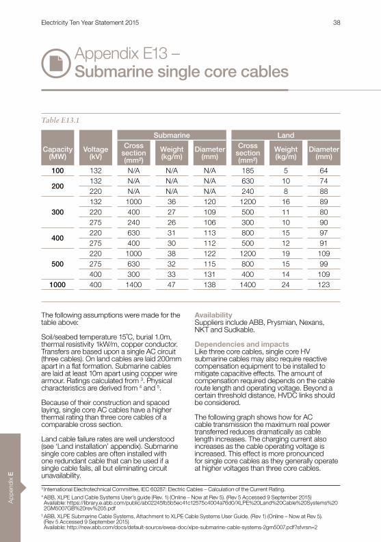
100 132 N/A N/A N/A 185 5 64
200132 N/A N/A N/A 630 10 74220 N/A N/A N/A 240 8 88
300132 1000 36 120 1200 16 89220 400 27 109 500 11 80275 240 26 106 300 10 90
400220 630 31 113 800 15 97275 400 30 112 500 12 91
500220 1000 38 122 1200 19 109275 630 32 115 800 15 99400 300 33 131 400 14 109
1000 400 1400 47 138 1400 24 123
Table E13.1
Appendix E13 – Submarine single core cables
The following assumptions were made for the table above:
Soil/seabed temperature 15˚C, burial 1.0m, thermal resistivity 1kW/m, copper conductor . Transfers are based upon a single AC circuit (three cables) . On land cables are laid 200mm apart in a flat formation. Submarine cables are laid at least 10m apart using copper wire armour . Ratings calculated from 3 . Physical characteristics are derived from 4 and 5 .
Because of their construction and spaced laying, single core AC cables have a higher thermal rating than three core cables of a comparable cross section .
Land cable failure rates are well understood (see ‘Land installation’ appendix) . Submarine single core cables are often installed with one redundant cable that can be used if a single cable fails, all but eliminating circuit unavailability .
AvailabilitySuppliers include ABB, Prysmian, Nexans, NKT and Sudkable .
Dependencies and impactsLike three core cables, single core HV submarine cables may also require reactive compensation equipment to be installed to mitigate capacitive effects . The amount of compensation required depends on the cable route length and operating voltage . Beyond a certain threshold distance, HVDC links should be considered .
The following graph shows how for AC cable transmission the maximum real power transferred reduces dramatically as cable length increases . The charging current also increases as the cable operating voltage is increased . This effect is more pronounced for single core cables as they generally operate at higher voltages than three core cables .
3 International Electrotechnical Committee, IEC 60287: Electric Cables – Calculation of the Current Rating .4 ABB, XLPE Land Cable Systems User’s guide (Rev . 1) (Online – Now at Rev 5) . (Rev 5 Accessed 9 September 2015) Available: https://library .e .abb .com/public/ab02245fb5b5ec41c12575c4004a76d0/XLPE%20Land%20Cable%20Systems%202GM5007GB%20rev%205 .pdf
5 ABB, XLPE Submarine Cable Systems, Attachment to XLPE Cable Systems User Guide . (Rev 1) (Online – Now at Rev 5) . (Rev 5 Accessed 9 September 2015) Available: http://new .abb .com/docs/default-source/ewea-doc/xlpe-submarine-cable-systems-2gm5007 .pdf?sfvrsn=2
Electricity Ten Year Statement 2015 38

Appendix E
Figure E13.2Maximum real power transfer in 275kV and 400kV cables with 100/0, 50/50 and 70/30 reactive compensation split between onshore and offshore (1000mm² copper cross section)
The 100/0 scenario is the cheapest but also the least effective – as all the reactive compensation is placed onshore, the weight requirements on the offshore platform are reduced substantially . For land cables it is
possible to install compensation mid-route if necessary .
It is more economical to use three core cabling for lower rated submarine connections .
275kV 70/30 275kV 50/50275kV 100/0400kV 70/30 400kV 50/50400kV 100/0
0 50 100
150
200
0
1000
600
500
400
300
200
100
700
800
900
MW
km
Electricity Ten Year Statement 2015 39

App
endi
x E
6 Nexans, Olivier Angoulevant, Offshore Wind China 2010 Bergen, 15th March 2010, Olivier Angoulevant (online) . (Accessed: 9 September 2015) . Available: http://www .norway .cn/PageFiles/391359/Nexans%20-%20Olivier%20Angoulevant .pdf
7 ABB, World’s longest 345kV AC submarine XLPE cable system: Bayonne Energy Centre project, New York Harbor, USA (online) . (Accessed: 9 September 2015) . Available: http://www04 .abb .com/global/seitp/seitp202 .nsf/c71c66c1f02e6575c125711f004660e6/ 2b7372bc835e78e6c125798800454000/$FILE/Project+Bayonne+US+345+kV+XLPE+subm .pdf
8 ABB, World’s most powerful three-core submarine cable: Little Belt Visual Enhancement Scheme, Denmark (online) . (9 September 2015) . Available: http://www05.abb.com/global/scot/scot245.nsf/veritydisplay/689213765eef0d49c1257c0e00243c4f/$file/Little%20belt%20brochure%202GM8001-gb%20korr3 .pdf
9 NKT, Intelligent Energy Transmission Solutions for On- and Offshore (online) . (Accessed: 9 September 2015) . Available: http://www.nktcables.com/~/media/Files/NktCables/download%20files/com/Offshore_Flyer.pdf
10 Prysmian, Prysmian: Euro 300 Million Contract Awarded By Terna for the Development of a New Submarine Power Link between Sicily and Italian Mainland (online) . (Accessed: 9 September 2015) . Available: http://investoren .prysmian .com/phoenix .zhtml?c=211070&p=irol-newsCorporateArticle&ID=1366416&highlight=
Project examples – CommissionednOrman Lange grid connection (2008):
1000MW, 400kV (max 420kV), 3 x 2 .4km AC single core submarine cable (3 x 1200 mm² CU) supplied by Nexans .6
n Bayonne Energy Centre project (2011): 602MVA, 345kV, 3 x 10 .4km AC single-core submarine cables, 3 x 1 .066km AC single-core underground cables . The AC submarine and underground cables are supplied by ABB .7
nLittle Belt project in Denmark (2013): 1100MW, 400kV (max 420kV), 6 x 5 .5km AC single core underground cables .8 The submarine and underground cables are supplied by ABB .
Project examples – Under constructionnGwynt y Môr offshore wind farm in
UK: 576MW, 132kV, 3 x 85km AC single core submarine cables (3 x 800 mm² CU) supplied by NKT .9 This project is expected to be commissioned in 2014 .
n Sicily – Italy mainland: 2000MW, 380kV, 6 x 38km AC single core submarine cables and 6 x 5 .4km underground cables . The submarine and underground cables are supplied by Prysmian .10
Appendix E13 – Submarine single core cables
Electricity Ten Year Statement 2015 40
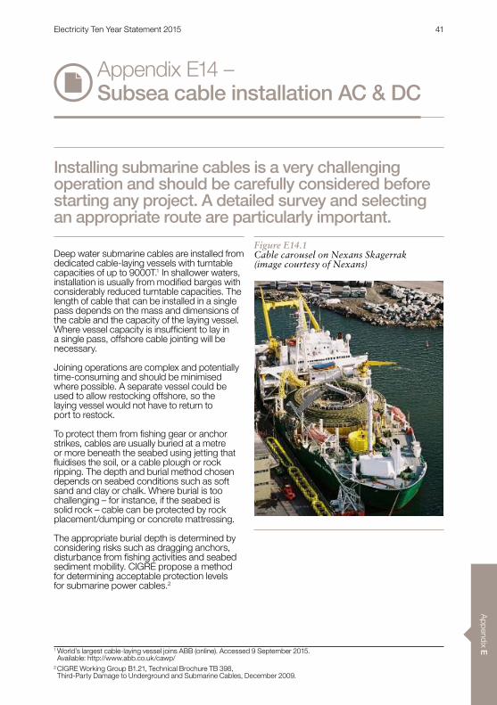
Appendix E
Appendix E14 – Subsea cable installation AC & DC
Deep water submarine cables are installed from dedicated cable-laying vessels with turntable capacities of up to 9000T .1 In shallower waters, installation is usually from modified barges with considerably reduced turntable capacities . The length of cable that can be installed in a single pass depends on the mass and dimensions of the cable and the capacity of the laying vessel . Where vessel capacity is insufficient to lay in a single pass, offshore cable jointing will be necessary .
Joining operations are complex and potentially time-consuming and should be minimised where possible . A separate vessel could be used to allow restocking offshore, so the laying vessel would not have to return to port to restock .
To protect them from fishing gear or anchor strikes, cables are usually buried at a metre or more beneath the seabed using jetting that fluidises the soil, or a cable plough or rock ripping . The depth and burial method chosen depends on seabed conditions such as soft sand and clay or chalk . Where burial is too challenging – for instance, if the seabed is solid rock – cable can be protected by rock placement/dumping or concrete mattressing .
The appropriate burial depth is determined by considering risks such as dragging anchors, disturbance from fishing activities and seabed sediment mobility . CIGRÉ propose a method for determining acceptable protection levels for submarine power cables .2
Installing submarine cables is a very challenging operation and should be carefully considered before starting any project. A detailed survey and selecting an appropriate route are particularly important.
1 World’s largest cable-laying vessel joins ABB (online) . Accessed 9 September 2015 . Available: http://www .abb .co .uk/cawp/
2 CIGRE Working Group B1 .21, Technical Brochure TB 398, Third-Party Damage to Underground and Submarine Cables, December 2009 .
Figure E14.1Cable carousel on Nexans Skagerrak (image courtesy of Nexans)
Electricity Ten Year Statement 2015 41

App
endi
x E
Appendix E14 – Subsea cable installation AC & DC
CapabilitiesCable laying rates of up to 500m/hr are possible but 200m/hr is average when laying and burying simultaneously . Ploughing is generally a faster operation but may not be suitable for all seabeds . Cables may be buried by the main installation vessel or by a smaller vessel at a later stage in installation (this approach can prove to be more economical as the large, expensive laying vessel is required for less time at sea3) . If this approach is taken, vessels can guard the unprotected cable until it is buried .
Vessels can operate twenty four hours a day, seven days a week if sea conditions are suitable. Water depth is not a significant factor, but changing seabed structure can influence the burial technologies used (jetting, rock ripping, ploughing) . Downtime during cable jointing operations, mobilisation and demobilisation costs and poor sea conditions (around 40% of the time in the winter) are significant factors to consider when calculating cable installation costs .
The use of bundled bipole cables in the case of HVDC links, or three core HVAC cables, rather than single core cables, may be preferred as it reduces the time a cable laying vessel is required at sea, although the installation and subsequent recovery of the cable if there is a fault is made more challenging . If jointing is necessary, separate burial in multiple passes may be a cost-effective way to reduce the number of offshore jointing operations . It is also possible to perform jointing operations on a separate vessel to the main laying vessel, which may positively impact project costs and timetables .3
Bundling cables can also reduce the overall rating of the cable system due to mutual heating effects . Laying the cables separately can increase rating up to 25% over that stated in these appendices . Each project needs a detailed cost-benefit analysis to establish the most economic laying arrangement, weighing installation costs against increases in the cost of the cable given the increase in conductor cross section necessary for bundled cables .
Each HVDC or HVAC submarine cable project tends to be unique and therefore requires its own engineering study in order to identify the best solution .
Typical failure rates for subsea cables are 0 .1 failures per 100km per year4, with a mean time to repair of two months5 but this could vary considerably with local conditions . Submarine cable systems have an expected lifetime of 30 to 40 years .3
3 Thomas Worzyk, Submarine Power Cables: Design, Installation, Repair, Environmental Aspects, Published 2009 ISBN 978-3-642-01270-9 .
4 CIGRE Working Group B1 .10, Technical Brochure TB 379: Update of Service Experience of HV Underground and Submarine Cable Systems, April 2009 .
5 Prysmian . Cableship Giulio Verne (online) . (Accessed: 9 September 2015) . Available: http://prysmiangroup.com/en/business_markets/markets/hv-and-submarine/about_us/cableship-giulio-verne/
Figure E14.2Sea Stallion 4 power cable plough (image courtesy IHC Engineering Business)
Electricity Ten Year Statement 2015 42
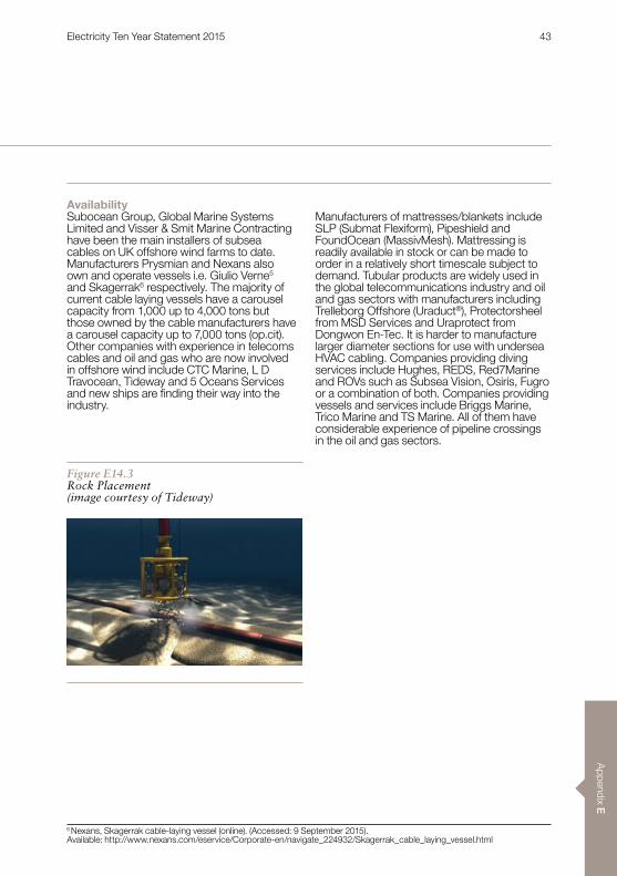
Appendix E
AvailabilitySubocean Group, Global Marine Systems Limited and Visser & Smit Marine Contracting have been the main installers of subsea cables on UK offshore wind farms to date . Manufacturers Prysmian and Nexans also own and operate vessels i .e . Giulio Verne5 and Skagerrak6 respectively . The majority of current cable laying vessels have a carousel capacity from 1,000 up to 4,000 tons but those owned by the cable manufacturers have a carousel capacity up to 7,000 tons (op .cit) . Other companies with experience in telecoms cables and oil and gas who are now involved in offshore wind include CTC Marine, L D Travocean, Tideway and 5 Oceans Services and new ships are finding their way into the industry .
Manufacturers of mattresses/blankets include SLP (Submat Flexiform), Pipeshield and FoundOcean (MassivMesh) . Mattressing is readily available in stock or can be made to order in a relatively short timescale subject to demand . Tubular products are widely used in the global telecommunications industry and oil and gas sectors with manufacturers including Trelleborg Offshore (Uraduct®), Protectorsheel from MSD Services and Uraprotect from Dongwon En-Tec . It is harder to manufacture larger diameter sections for use with undersea HVAC cabling . Companies providing diving services include Hughes, REDS, Red7Marine and ROVs such as Subsea Vision, Osiris, Fugro or a combination of both . Companies providing vessels and services include Briggs Marine, Trico Marine and TS Marine . All of them have considerable experience of pipeline crossings in the oil and gas sectors .
6 Nexans, Skagerrak cable-laying vessel (online) . (Accessed: 9 September 2015) . Available: http://www.nexans.com/eservice/Corporate-en/navigate_224932/Skagerrak_cable_laying_vessel.html
Figure E14.3Rock Placement (image courtesy of Tideway)
Electricity Ten Year Statement 2015 43

App
endi
x E
Dependencies and impactsThere are a number of companies that can lay short cables near shore and in shallower waters . Larger vessels with the capability of long cable runs offshore, e .g . 70-100km, are limited and the investment in such vessels will to some degree be dictated by the certainty of offshore wind projects going ahead . Justifying investment in new vessels requires a pipeline of commitments .
The forces involved in offshore cable installation are large, and there is always a risk of damage to the cables . Factors to consider included cable tension and side wall pressure (SWP) over the laying wheel . Both of these depend on cable weight, depth of installation and the impact of vessel motion in swells . CIGRÉ type testing may not fully account for the dynamic forces1 and detailed computer modelling is hence recommended . Care must be taken if separate parties are used for separate cable supply and installation, as it may be difficult to identify where liability lies if there are problems .7
Thermal bottlenecks that effectively de-rate the entire cable system may occur in the J tubes connecting the cables to offshore platforms and it may be best to sit these on the north side of a platform to minimise solar heating .
Wherever possible, routes should be chosen to avoid the crossing subsea obstacles such as other cables or pipelines . Where it is necessary, it can be accomplished through the use of concrete mattresses, tubular protective products or rock dumping . It should be noted that other subsea assets, particularly power cables, may introduce a heat source that could
cause a thermal bottleneck unless the crossing is appropriately designed .
The number of obstacles will depend on the location of the offshore substation, cable routes, landfall and desired onshore connection point, as well as the particular sea area . Oil and gas pipelines are predominant in the North Sea, but towards the English Channel there are more telecommunications cables . The rights to cross an obstacle, and the method used to do so, may need to be negotiated with the obstacle owner . Up to half of obstacles encountered may be disused pipes/cables left in situ . Tubular products are designed to be fitted during subsea cable laying operations but obstacle crossing using mattresses would typically be done in advance, minimising down time on the cable laying vessel . Putting several crossings together in an installation programme would be more cost effective, with mattresses supplied to site by barge .
Detailed cable route surveys are essential and will of course consider obstacle crossing as well as other restrictions that impact on cable laying such as subsea conditions (seabed temperature, makeup, thermal resistivity etc .), munitions dumps, and fishing areas.
Project examplesnNysted, Thanet, Greater Gabbard,
Westermost Rough, Beatrice, Horns Rev2, Sheringham Shoal, Walney 2 and Ormonde, Anholt, Gwynt y Môr
nNorNed HVDC cable .
Appendix E14 – Subsea cable installation AC & DC
7 J .E . Skog, NorNed-Innovative Use of ProvenTechnology, Paper 302, CIGRE SC B4 2009Bergen Colloqium .
Electricity Ten Year Statement 2015 44

Appendix E
Appendix E15 – Offshore substation platforms
This type of platform’s main function is to provide reactive compensation as AC cables reach their economical transmission distance . But the mechanical vibration issues that come with a lighter platform would have to be overcome before cheaper and more traditional AC technology could be used .
Offshore platforms house the electrical equipment for generation collection and transmission to shore . Multiple platforms may be required depending on the project’s capacity and how the platform will be used . A separate platform is needed where offshore transmission is via HVDC . All types of platform need cooling radiators, pumps, fans, transformers, switchgear, protection, control and some need living quarters .
Offshore platforms need extra equipment including emergency accommodation, life-saving equipment, cranes for maintenance, winch to hoist the subsea cables, backup diesel generator, fuel, helipad and the J-tube supports that house the subsea cables as they rise from the seabed to the platform topside, where they are terminated .
HVDC equipment on the platform typically weighs from 2,000 tonnes to over 5,000 tonnes . HVDC platform topside weights are difficult to predict as they depend on factors such as topside designs, limitation and substructures type .
AC collection platforms are generally used to collect wind generation. The voltage is stepped up there for transmission to shore via AC or DC technology. As more experience is gained from using AC platforms, other techniques may be explored to optimise offshore AC transmission by using compensation platforms.
Figure E15.1Thanet substation under construction(image courtesy SLP Engineering)
Electricity Ten Year Statement 2015 45

App
endi
x E
Appendix E15 – Offshore substation platforms
The supporting substructure for lower rated HVDC platform consists of four legs or piles with tubular bracings in between them . This method – known as ‘jacket’ – can range from four to eight legs piled into the seabed . The number of legs needed depends on seabed conditions and platform weight . Jackets used in North Sea waters are usually about 30 to 50 metres deep and platforms are generally 25 to 40 metres above sea level, depending on wave height .
All platforms are constructed and fully fitted out onshore, then transported to the offshore site/ wind farm .
As the need for larger platforms increases, alternative designs, such as self-installing platforms, are being introduced . A self-installing platform is floated out on a barge; hydraulic jack-up legs descend to the sea bed then lift the topside off the barge . An advantage of the suction bucket technologies associated with self-installing platforms is that they can be installed in differing sea bed and soil conditions, more cheaply than pile driving operations . Using suction buckets involves pumping water and soil from the cavity of the bucket during the installation . This creates a pressure difference that firmly roots the foundation to the sea bed.
Another option is to use gravity based structure (GBS) . These are semi-submersible platforms that are floated out to location and then sunk onto the seabed using ballast materials . The extra material needed makes it an expensive method, but the benefits are higher than most design types .
Each platform types has its own risks and challenges that need to be overcome for successful design, construction and commissioning .
CapabilitiesThe size of the platform depends on the equipment it houses . For every additional tonne or square meter of space on the topside, additional support steel work and jacket reinforcement is required .
The depth of the water is another key factor in the design of the platform; hence most wind farms are located in shallow seas where possible .
AC platforms tend to use GIS equipment so they are more compact and densely populated than DC platforms (where AIS equipment is used) .
HVDC platform sizes are usually based on the assumption that the HVDC scheme is a balanced monopole (a bipolar system would require more space) .
Table E15 .1 gives platform dimensions for different substation power ratings .
AvailabilityConstruction timescales for AC and HVDC offshore platforms depend on the primary equipment . Delivery delays of the primary equipment impact the schedule for both AC and DC platforms . The installation timescale for an HVDC platform of between 1,000MW-1,500MW is about five years, while a platform of rating 1,800MW or above would take about seven years as extra time is needed to carry out feasibility studies and for design development . For larger platforms, there could also be extensions to the fabrication facilities .
The main UK capabilities are from SLP, Heerema and McNulty (fabrication yards in Lowestoft, Tyneside and Fife) and potential facilities in Northern Ireland such as Harland & Wolff . There is great amount of experience in Germany where Nordic Yards have worked on the majority of HVDC platforms in the German North Sea .
Electricity Ten Year Statement 2015 46

Appendix E
Table E15.1Platform dimensions
Platform facility Water depth (m) Size (m)W H L
Total weight (tonnes)Including plant
300MW AC 20–40 20, 18, 25 1,800500MW AC 30–40 31, 18, 39 2,100800MW DC 30–40 62, 44, 36 3,2001,000MW DC 40+ 74, 64, 38 12,000Accommodation 40+ 35, 21, 35 18,000
Dependencies and impactsPlatform delivery lead times and capacity depend on fabrication yard capability and vessel restrictions, such as availability and lift capability . The maximum lift capacity for the largest vessels had been 14,000 tonnes, but this now been increased with the arrival of the Pioneering Spirit (previously named Pieter Schelte) with a topside lift capacity of 48,000 tonnes and a jacket lift capacity of 25,000 tonnes . For platforms lighter than 5,000 tonnes, there are more available vessels . Due to competition from other industries, these vessels may have to be booked up to two years in advance . A combination of installation vessels can be used, but differing crane lengths can complicate offshore installation by adding further delays . And of course installation needs favourable weather and sea conditions .
Suppliers that have previously serviced the oil and gas sector can construct and install topsides and jackets . Electrical equipment needs to be provided by the major equipment manufacturers . As fabrication facilities are limited, the offshore wind industry has to compete with the oil and gas sector .
The platform dimensions are the other limiting factor . The largest fabrication yard has a dimension of 340m x 67m x 72m, which supports the claims that a single 2GW+ platform can be constructed . Due to the limitations on width, a converter design must fit within this constraint. The fabricator would need to be suitably compensated for a single large platform taking up foreseeable capability on their yards .
This supports the message from the industry, that two or three platforms of a similar design of 1GW would be more efficient if they could be built in parallel with generation .
Platforms used as landing or dropping points must adhere to Civil Aviation Authority (CAA) regulations, which may impact on the level of emergency equipment and safety procedures required .
An asset life of over 30 to 50 years would significantly increase the capital and operational cost due to increased weight, anti-corrosion specifications and operation/maintenance regimes .
Figure E15.2DolWin Beta HVDC topsides and jacket(image courtesy of ABB)
Electricity Ten Year Statement 2015 47

App
endi
x E
Appendix E15 – Offshore substation platforms
Project examplesnThanet platform AC collector:
300MW, 30 x 18 x 16m, 1,460t jacketnGreater Gabbard AC collector:
500MW, 39 x 31 x 18m, 2,100t, jacketnSheringham Shoal:
315MW, 30 .5 x 17 .7 x 16m, monopolenHelWin Beta HVDC platform:
690MW, 98 x 42 x 28m, 12,000t, self-installnDolWin Alpha HVDC platform:
800MW, 62 x 42 x 36m, 15,000t, jacketnDolWin Beta HVDC platform:
924MW 100 x 74 x 83m, 20,000t, GBS
Figure E15.3Pioneering Spirit (previously named Pieter Schelte)
Additional informationn DNV-OS-J201, Offshore Substations for Wind Farms (online) . (Accessed: 09 September 2015) .
n J . Finn, M Knight, C Prior, Designing substations for offshore connections, CIGRÉ Paris Session B3-201, August 2008 .
n Heerema Zwijndrecht (online) . (Accessed: 08 September June 2015) . Available: http://hfg .heerema .com/content/yards/heerema-zwijndrecht-nl/
n Heerema Zwijndrecht (online), (Accessed: 17 June 2014) . Available: http://hfg .heerema .com/content/yards/heerema-zwijndrecht-nl/
n Allseas, Pioneering Spirit (online) . (Accessed: 08 Septmeber 2015) . Available: http://www .allseas .com/uk/19/equipment/pieter-schelte .html http://www .allseas .com/public/2015-0209%20New%20name%20for%20 Allseas%20single-lift%20vessel .pdf
n Financial times article (online) .(Accessed: 08 September 2015) Available: http://www .ft .com/cms/s/0/e213d176-ae32-11e4-8d51-00144feab7de .html
n Nordic Yards (online) . (Accessed 08 September 2015) Available: http://www.nordicyards.com/nordicyards.html#_facilities
Electricity Ten Year Statement 2015 48

Appendix E
The thyristor can be switched on by a gate signal and continues to conduct until the current through it reaches zero . A CSC therefore depends on the voltage of the AC network to which it is connected for commutation of current in its valves . A CSC HVDC system is larger and heavier than a voltage source converter (VSC) one so will be more difficult to implement in an offshore location .
CapabilitiesCSC HVDC is well suited to transmission of large quantities of power over long distances . An installation rated at 8000MW at a voltage of ±800kV using overhead lines was commissioned in 20141,2 . Further development of this technology is a continual process, a new ultra HVDC (UHVDC) ±1100kV/5000A Zhundong–Chengdu project in China is being considered by the China electric power research institute (CEPRI)3 .
Because of the commutation process, the converter current lags the phase voltage and the CSC absorbs reactive power . The CSC also generates non-sinusoidal currents and requires AC filtering to avoid exceeding harmonic limits in the AC network . Reactive compensation and AC harmonic filters are therefore provided and account for around 40 to 60% of the converter station footprint4 . Indicative typical dimensions for a 1000MW CSC located onshore are about 200m x 175m x 22m, but the footprint is highly
dependent on the AC harmonic filtering needed at the particular location .
Transmission losses are typically 0 .85% of transmitted power (per end)5 .
Most of the HVDC transmission systems in service are the current source converter (CSC) type. This well-established technology has been in use since the 1950s, using thyristor valves since the 1970s.
Figure E15.1Ballycronan More converter station (Moyle Interconnector) (image courtesy of Siemens)
1 CEPRI, Southern Hami-Zhengzhou ±800kV UHVDC Transmission Project, (Online), (Accessed: July 22, 2015) . Available: http://www.cepri.com.cn/aid/details_72_272.html
2 Siemens, 5000A DC Siemens commutation breaker successfully tested in China, (Online), (Accessed: July 22, 2015) . Available: http://www.ptd.siemens.de/141216_Newsletter_5000A_MRTB.pdf
3 Liu, Z ., Gao, L ., Wang, Z ., Yu, J ., Zhang, J ., Lu, L ., ‘R&D progress of ±1100kV UHVDC technology’, Paper B4-201, CIGRÉ 20124 Carlsson, L ., Flisberg, G ., Weimers, L ., ‘Recent evolution in classic HVDC’, (Online),5 Andersen, B .R . and Zavahir, M ., ‘Overview of HVDC and FACTS’, CIGRÉ B4 Colloquium, Bergen, 2009
Appendix E16 – HVDC: current source converters
Electricity Ten Year Statement 2015 49

App
endi
x E
Appendix E16 – HVDC: current source converters
6 Vancers, I ., Christofersen, D .J ., Leirbukt, A . and Bennet, M .G ., ‘A survey of the reliability of HVDC systems throughout the world during 2005 – 2006’, Paper B4-119, CIGRÉ 2008
AvailabilitySuppliers include ABB, Alstom Grid and Siemens, although several eastern suppliers such as CEPRI can also offer such products . Lead times depend on project requirements and are typically 2 .5-3 years . The lead times may be dominated by any associated cable manufacturing time .
Dependencies and impactsCSCs require a relatively strong AC network for valve commutation . In general, the short circuit ratio (SCR), defined as the short circuit power or fault level divided by the rated HVDC power, should be at least 2 .5 . Recent developments such as capacitor commutated converters have reduced the SCR requirement to around 1 .0, but in either case to use a CSC offshore would require a voltage source such as a static compensator (STATCOM) or rotating machine to provide sufficient voltage for successful valve commutation .
CSC technology can be used with mass impregnated cable or overhead line to form the HVDC connection between the converter stations. A reversal of the power flow direction requires a change in the polarity of the DC voltage . When using mass impregnated cables, this can mean a wait before re-starting power
transfer in the opposite direction . Extruded cables may be used where no reversal of power flow is required.
Although mass impregnated cables have higher ratings than extruded cable, the achievable transmission capacity may still be limited by the ratings of the cable rather than the converter . CIGRÉ Advisory Group B4 .045 conducts an annual survey of the reliability of HVDC systems and publishes the results at the CIGRÉ Session held in Paris every two years6 . The reports contain data on energy availability, energy use, forced and scheduled outages and provide a continuous record of reliability performance for most HVDC systems in the world since they first went into operation.
Electricity Ten Year Statement 2015 50

Appendix E
Project examplesnHVDC cross-Channel link the link connects
the French and British transmission systems7 . The link consists of two separate bipoles, each with a transmission capacity of 1000MW at a DC voltage of ±270kV . Each bipole can operate as a monopole to transfer 500MW allowing operational flexibility. The cross-Channel link went into operation in 1986 .
n BritNed the link connects the British and Dutch transmission systems8 . The link is a 1000MW bipole that operates at ±450kV over a 260km subsea cable . The link was commissioned in early 2011 . The converter stations were supplied by Siemens and the cables by ABB .
nBasslink the link connects Victoria, on the Australian mainland, to George Town, Tasmania, by means of a circuit comprising 72km overhead line, 8km underground cable and 290km submarine cable9 . The connection is monopolar with a metallic return . It has a nominal rating of 500MW, operates at a DC voltage of 400kV and went into operation in 2006 . The converter stations were supplied by Siemens and the cables by Prysmian .
nNorNed HVDC the link connects the transmission systems in Norway and the Netherlands by means of a 580km
submarine cable10 . The connection has a transmission capacity of 700MW at a DC voltage of ±450kV and went into operation in 2008 . The converter stations were supplied by ABB and the cables by ABB and Nexans .
nSouthern Hami – Zhengzhou this 2210km link connects Hami in north western region of China and Zhengzhou, middle China, going through six provinces of China . The link was commissioned in January, 2014 and has a world record 8,000MW converter capacity at a rated DC voltage/current of ±800kV/5000A1 . The whole project was executed by CEPRI, China and HVDC components were supplied by Chinese and other international manufacturers1,2 .
nNorth-East Agra this link will have an 8,000MW converter capacity, including a 2000MW redundancy, to transmit clean hydroelectric power from the north eastern and eastern regions of India to the city of Agra across a distance of 1,728km11 . The project has a ±800kV voltage rating and will form a multi-terminal solution that will be one of the first of its kind in the world (the others being the New England–Quebec scheme and the HVDC Italy–Corsica–Sardinia (SACOI) link) . The project is scheduled to be commissioned in 2016 . The project is being executed by ABB .
7 Dumas, S ., Bourgeat, X ., Monkhouse, D .R . and Swanson, D .W ., ‘Experience feedback on the Cross-Channel 2000MW link after 20 years of operation’, Paper B4-203, CIGRÉ 2006
8 Siemens, BritNed, (Online), (Accessed: June 26, 2014) . Available: http://www .energy .siemens .com/hq/pool/hq/ power-transmission/HVDC/HVDC-Classic/pm-pdf/Press_BritNed_2011_04_01_e.pdf
9 Siemens, Basslink, (Online), (Accessed: June 26, 2014) . Available: http://www.energy.siemens.com/hq/pool/hq/power-transmission/HVDC/HVDC-Classic/pm-pdf/pm_basslink_neu.pdf
10 ABB, NorNed, (Online), (Accessed: June 26, 2014) . Available: http://new .abb .com/systems/hvdc/references/norned11 ABB, North-East Agra, (Online), (Accessed: June 26, 2014) .
Available: http://new .abb .com/systems/hvdc/references/north-east-agra
Electricity Ten Year Statement 2015 51
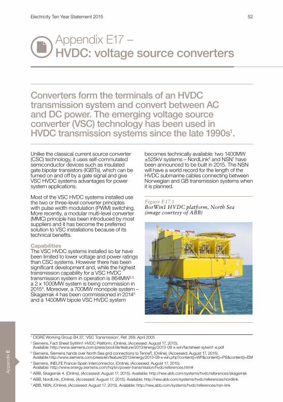
App
endi
x E
Appendix E17 – HVDC: voltage source converters
Unlike the classical current source converter (CSC) technology, it uses self-commutated semiconductor devices such as insulated gate bipolar transistors (IGBTs), which can be turned on and off by a gate signal and give VSC HVDC systems advantages for power system applications .
Most of the VSC HVDC systems installed use the two or three-level converter principles with pulse width modulation (PWM) switching . More recently, a modular multi-level converter (MMC) principle has been introduced by most suppliers and it has become the preferred solution to VSC installations because of its technical benefits.
CapabilitiesThe VSC HVDC systems installed so far have been limited to lower voltage and power ratings than CSC systems . However there has been significant development and, while the highest transmission capability for a VSC HVDC transmission system in operation is 864MW2,3,
a 2 x 1000MW system is being commission in 20154 . Moreover, a 700MW monopole system – Skagerrak 4 has been commissioned in 20145
and a 1400MW bipole VSC HVDC system
becomes technically available: two 1400MW ±525kV systems – NordLink6 and NSN7 have been announced to be built in 2015 . The NSN will have a world record for the length of the HVDC submarine cables connecting between Norwegian and GB transmission systems when it is planned .
Converters form the terminals of an HVDC transmission system and convert between AC and DC power. The emerging voltage source converter (VSC) technology has been used in HVDC transmission systems since the late 1990s1.
Figure E17.1BorWin1 HVDC platform, North Sea(image courtesy of ABB)
1 CIGRÉ Working Group B4 .37, ‘VSC Transmission’, Ref . 269, April 20052 Siemens, Fact Sheet SylWin1 HVDC Platform, (Online), (Accessed: August 17, 2015) .
Available: http://www .siemens .com/press/pool/de/feature/2013/energy/2013-08-x-win/factsheet-sylwin1-e .pdf3 Siemens, Siemens hands over North Sea grid connections to TenneT, (Online), (Accessed: August 17, 2015) .
Available: http://www .siemens .com/press/en/feature/2013/energy/2013-08-x-win .php?content()=WP&content()=PS&content()=EM4 Siemens, INELFE France-Spain Interconnector, (Online), (Accessed: August 17, 2015) .
Available: http://www .energy .siemens .com/hq/en/power-transmission/hvdc/references .htm#5 ABB, Skagerrak 4, (Online), (Accessed: August 17, 2015) . Available: http://new .abb .com/systems/hvdc/references/skagerrak6 ABB, NordLink, (Online), (Accessed: August 17, 2015) . Available: http://new .abb .com/systems/hvdc/references/nordlink7 ABB, NSN, (Online), (Accessed: August 17, 2015) . Available: http://new .abb .com/systems/hvdc/references/nsn-link
Electricity Ten Year Statement 2015 52

Appendix E
VSCs can generate or absorb reactive power and allow active and reactive power to be controlled independently . VSCs do not depend on the presence of a synchronous AC voltage for their operation and may be used to feed weak or passive AC networks . VSC technology can restart a dead AC network if there is a blackout . It can also provide voltage support (static compensator (STATCOM) operation) to a local AC network if there is a fault or during system instability .
A VSC has a smaller footprint than a CSC with equivalent ratings . Indicative typical dimensions for a 1000MW VSC located onshore are 90m x 54m x 24m8 .
Converter losses are approximately 1% of transmitted power (per end) for a MMC-based HVDC converter station9 .
VSCs can meet the requirements of the system operator – transmission owner code at the interface point including reactive power capability, voltage control, fault ride through capability, operation over a range of frequencies and can provide power oscillation damping .
Since the power flow is reversed without changing the polarity of the DC voltage, and since the IGBT valves do no suffer commutation failures, VSC technology is, in principle, well suited to multi-terminal applications .
VSC is a practical solution where an offshore wind farm requires an HVDC connection .
AvailabilitySuppliers include ABB, Siemens and Alstom Grid, with other potential eastern world suppliers also able to deliver VSC solutions .
Lead times depend on the requirements of a given project and are typically 2–3 years . The lead time for a project may be dominated by any associated cable manufacturing time .
Dependencies and impactsThe ability to reverse power flow without changing the voltage polarity allows VSC HVDC transmission systems to use extruded cables which are cheaper than the alternative mass impregnated cables . However, where extruded cables are used, the achievable transmission capacity may be limited by the ratings of the cable rather than the converter .
Experience with VSC technology in HVDC systems dates from the late 1990s . Although their use is increasing, there is limited information on the reliability and performance .
Figure E17.2BorWin1 offshore 400MW converter
8 ABB, ‘It’s time to connect – Technical description of HVDC Light® technology’, (Online), (Accessed: June 17, 2014) . Available: http://www05.abb.com/global/scot/scot221.nsf/veritydisplay/2742b98db321b5bfc1257b26003e7835/$file/Pow0038%20R7%20LR .pdf
9 Jacobson, B . et al, “VSC-HVDC Transmission with Cascaded Two-Level Converters”, 2010, CIGRÉ B4-110
Electricity Ten Year Statement 2015 53

App
endi
x E
Project ExamplesnBorWin1 the project connects the BARD
offshore 1 wind farm to the German transmission system by means of a 125km HVDC circuit comprising submarine and land cables10 . The connection has a transmission capacity of 400MW at a DC voltage of ±150kV and has been commissioned in 2012 . The converter stations and cables were supplied by ABB . The project is the first application of HVDC technology to an offshore wind farm connection .
nINELFE France-Spain Interconnector this project is an interconnector project that will interconnect the French and Spanish transmission systems . It consists of two 1GW bipole HVDC links with a transmission distance of about 65km with underground cables in trenches and in a tunnel . The total power capacity will be 2GW and both bipoles will operate at a DC voltage of ±320kV . The link is being commissioned in 20154 .
nSylWin1 the project connects the Dan Tysk wind farm to the German transmission system by means of HVDC submarine/land cables with a total length of 205km . The connection has a transmission capacity of 864MW at a DC voltage of ±320kV2 . The converters are supplied by Siemens . The connection has been in commercial operation since June 2015 and currently is the world’s largest VSC system for an offshore wind farm connection3 . Nan’ao Multi-terminal HVDC Project in China’s transmission system, a three-terminal VSC HVDC project with rated DC voltage of ±160kV and power ratings of 200/100/50MW respectively . It has been put into operation since December 2013 as the world’s first multi-terminal VSC HVDC project. This project is situated on Nan’ao Island, Guangdong Province of China with the aim to bring dispersed wind power generated on Nan’ao Island to mainland AC networks of Guangdong Province through a mixture of DC overhead lines, land/sea cables with total length of 32km11 .
Appendix E17 – HVDC: voltage source converters
10 ABB, BorWin1 HVDC Light, (Online), (Accessed: June 17, 2014) . Available: http://new .abb .com/systems/hvdc/references/borwin1
11 RXPE, Nan’ao MTDC Project’, (Online), (Accessed: June 17, 2014) . Available: http://www .rxpe .co .uk/index .php?m=content&c=index&a=show&catid=1&id=30
Electricity Ten Year Statement 2015 54

Appendix E
The plastic insulation is extruded over a copper or aluminium conductor (copper has a lower resistance and thus a higher power density, although it is heavier and more expensive than aluminium) and covered with a watertight sheath . This sheath is usually made of extruded seamless lead for submarine cables, or of welded aluminium laminate for land cables . A further protective polyethylene plastic coating completes the design .
Extruded XLPE insulation is a relatively new entry to the HVDC cable market, which up until now has been dominated by mass impregnated (MI) cables . XLPE-insulated cables are generally mechanically robust and they may operate at higher temperatures (70˚C) than MI cable designs (aside from polypropylene-laminated MI) . This allows them to carry more current for a given conductor cross section .
Cable intended for submarine use has an additional layer of galvanised steel wire armour . This increases its tensile strength so it can better withstand the stresses of submarine installation . The armour is usually a single layer of wires wound around the cable, covered in a serving of bitumen-impregnated polypropylene yarn to reduce corrosion . In deeper waters, or over rocky seabeds, a double layer may be used . Submarine cables usually use copper as the conductor, while aluminium is often used for land cables .
CapabilitiesExtruded HVDC cables are available in voltages up to 525kV . The table below gives an example of cable systems for the stated power transfers, although actual cable system designs will vary from project to project .
Most extruded HVDC cables use cross-linked polyethylene (XLPE) for their insulation. Other types of plastic insulation materials have been developed.
Figure E18.1(image courtesy of Prysmian)
Appendix E18 – HVDC: extruded cables
Electricity Ten Year Statement 2015 55
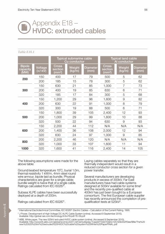
App
endi
x E
Appendix E18 – HVDC: extruded cables
The following assumptions were made for the above table:
Ground/seabed temperature 15˚C, burial 1.0m, thermal resistivity 1 kW/m, 4mm steel round wire armour, bipole laid as bundle . Physical characteristics are given for a single cable; bundle weight is twice that of a single cable . Ratings calculated from IEC 602871 .
Subsea XLPE cables have been successfully deployed at a depth of 200m .
Ratings calculated from IEC 602871 .
Laying cables separately so that they are thermally independent would result in a reduced conductor cross section for a given power transfer .
Several manufacturers are developing products in excess of 300kV . Far East manufacturers have had cable systems designed at 500kV available for some time2 and the recently pre-qualified cable at 400kV has just been bought by a European consortium. The first European cable supplier has recently announced the completion of pre-qualification tests at 525kV3 .
Table E18.1
Typical submarine cableCu conductor
Typical land cableAl conductor
Bipole capacity
(MW)
Voltage(+/-kV)
Cross section(mm²)
Weight(kg/m)
Diameter(mm)
Cross section(mm²)
Weight(kg/m)
Diameter(mm)
200150 400 17 79 500 5 62200 185 15 78 300 5 62
300150 630 21 85 1,000 7 73200 400 19 85 630 6 71320 185 17 84 300 5 68
400150 1,200 29 96 1,600 9 82200 630 22 91 1,000 8 79320 300 19 88 500 6 71
500150 1,800 39 105 2,400 12 93200 1,000 29 99 1,600 10 88320 500 22 94 630 9 93
600150 2,200 44 112 N/A N/A N/A200 1,400 36 108 2,000 12 94320 630 24 97 1,000 9 85
800200 2,200 46 120 N/A N/A N/A320 1,000 33 107 1,600 11 94
1000 320 1,600 41 116 2,400 14 105
1 International Electrotechnical Committee, IEC 60287: Electric Cables – Calculation of the Current Rating, 1995 . 2 J Power, Development of High Voltage DC-XLPE Cable System (online) . Accessed 9 September 2015) .
Available: http://global-sei .com/technology/tr/bn76/pdf/76-09 .pdf3 ABB, White paper, The new 525kV extruded HVDC cable system (online) . (Accessed 9 September 2015) .
Available: http://www05.abb.com/global/scot/scot221.nsf/veritydisplay/7caadd110d270de5c1257d3b002ff3ee/$file/The%20new%20525%20kV%20extruded%20HVDC%20cable%20system%20White%20PaperFINAL .pdf
Electricity Ten Year Statement 2015 56
Appendix E
AvailabilitySuppliers: the ABB cable factory in Karlskrona, Sweden is being expanded to accommodate the manufacture of submarine cables . Meanwhile, the Prysmian cable factory in Naples, Italy is being expanded to supply the submarine DC cable for the offshore wind farm market .
In the US, manufacturing capability has increased with recent investment in factories by European Suppliers . The Prysmian and Nexans facilities are in South Carolina and focused on the production of extruded underground and submarine cables; while ABB has recently sold its North Carolina factory, which focused on EHV AC and DC underground cables .
Supply and installation times depend on the length of cable required, and the design and testing necessary (using an already proven cable design removes the development lead time), but are generally in the range of 2-3 years .
Dependencies and impactsWith all plastic insulation, there is minimal environmental impact in the case of external damage . XLPE cable joints are pre-fabricated and so need less time per joint than that required for MI cables . This means they’re likely to be less expensive. This has benefits for land applications where individual drum lengths are shorter and there are a correspondingly higher number of joints . For long submarine cable connections, the manufacturing extrusion lengths of the XLPE cable are shorter than that for similar MI cable . This means a higher number of factory joints are necessary .
At the moment, XLPE extruded cables are only used with voltage source converter (VSC) HVDC systems due to the risk represented by voltage polarity reversal and space charge effects4 . Some suppliers are testing extruded cables to meet CIGRÉ LCC-type test requirements .
4 Electric Power Research Institute, DC Cable Systems with Extruded Dielectric, Dec 2004 . Compiled by Cable Consulting International .
Electricity Ten Year Statement 2015 57

App
endi
x E
Project examples – CommissionednTrans Bay Cable (2010): 400MW, ±200kV
DC, bipole, 5km underground AC and DC cables, 2 x 80km DC submarine cable supplied by Prysmian5 .
nValhall (2011): 78MW, 150kV DC, monopole, 292km DC submarine cable supplied by Nexans6 .
nBorWin1 Offshore Wind Farm (2012): 400MW, ±150kV DC, bipole, 2 x 75km DC underground cable (2,300mm² AI, 96mm diameter, 11kg/m), 2 x 125km DC submarine cable (1,200mm² CU, 98mm diameter, 29kg/m) . The DC submarine and underground cables are supplied by ABB7 .
nEast West Interconnector (2013): 500MW, ±200kV DC, bipole, 2 x 75km DC underground cable (2,210mm² AI, 107mm diameter, 12kg/m), 2 x 186km DC submarine cable (1,650mm² CU, 117mm diameter, 39kg/m) . Submarine and underground cables are supplied by ABB8 .
nINELFE, France-Spain: 2 x 1,000MW, ±320kV, 2 x bipole, 4 x 64km DC land route (2,500mm² CU, 128mm diameter, 34kg/m) supplied by Prysmian9 . This project was commissioned in 2015 .
nDolWin1 Offshore Wind Farm: 800MW, ±300kV DC, bipole, 2 x 90km DC underground cable . Two types of cable: 1) 2,000mm² AI, 118mm diameter, 14kg/m; 2) 1,600mm² CU, 114mm diameter, 33kg/m). 2 x 75km DC submarine cable . Two types: 1) 1,000mm² CU, 115mm diameter, 34kg/m; 2) 1,600mm² CU, 125mm diameter, 44kg/m)10 . The DC submarine and underground cables are supplied by ABB . This project has recently been commissioned .
Project examples – Under constructionnNEMO LINK: 1000MW, ±400kV DC Bipole
142km route length, supplied by J-Power of Japan .11
Appendix E18 – HVDC: extruded cables
5 Prysmian, Trans Cable Bay – Interconnecting the US (online) . (Accessed: 9 September 2015) . Available: http://prysmiangroup.com/en/corporate/about/special_projects/trans-bay/
6 Nexans, Nexans wins €98 million subsea power cable contract for BP’s Valhall Power from Shore project (online) . (Accessed: 9 September 2015) . Available: http://www.nexans.no/eservice/Norway-no_NO/navigatepub_142647_-3665/Nexans_wins_98_million_subsea_power_cable_contract.html
7 ABB, Grid connection of offshore wind farms – BorWin1 (online) . (Accessed: 9 September 2015) . Available: http://new .abb .com/systems/hvdc/references/borwin1
8 ABB, East-West Interconnector: connecting Ireland and Britain (online) . (Accessed: 9 September 2015) . Available: http://new .abb .com/systems/hvdc/references/east-west-interconnector
9 Prysmian, HVDC Cable System for Land Transmission (online) .10 ABB, DolWin1 – Further Achievements in HVDC Offshore Connections (online) . (Accessed: 9 September 2015) .
Available: http://www05.abb.com/global/scot/scot221.nsf/veritydisplay/0817901b2514978ec1257c3000435c3a/$file/DolWin1%20further%20achievements%20in%20HVDC%20offshore%20connections .pdf
11 J Power, J-Power wins contract with NEMO LINK for HVDC Subsea Interconnector Cable system between UK and Belgium . (online) . (Accessed 9 September 2015) . Available: http://www .jpowers .co .jp/pr/150608/150608e .pdf
Electricity Ten Year Statement 2015 58
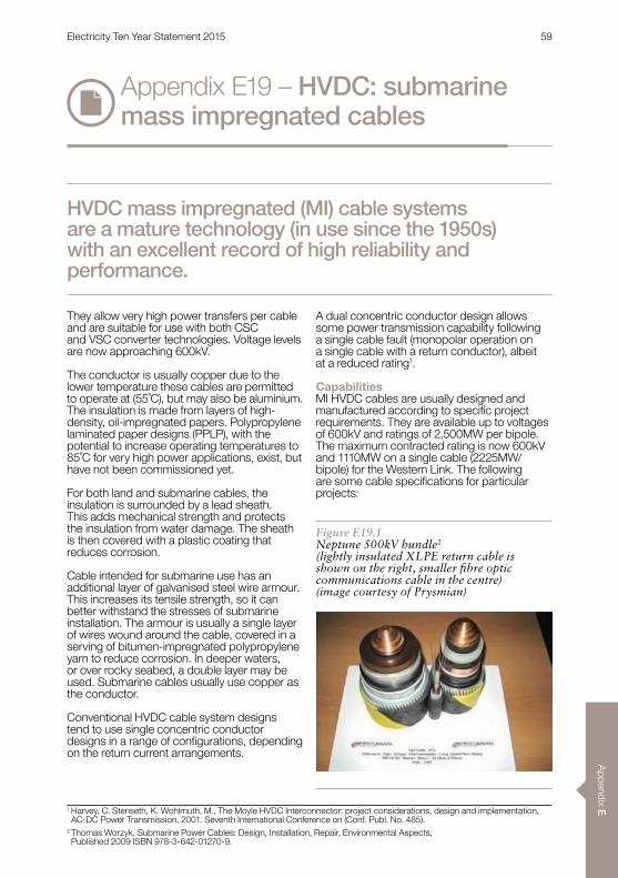
Appendix E
Appendix E19 – HVDC: submarine mass impregnated cables
They allow very high power transfers per cable and are suitable for use with both CSC and VSC converter technologies . Voltage levels are now approaching 600kV .
The conductor is usually copper due to the lower temperature these cables are permitted to operate at (55˚C), but may also be aluminium. The insulation is made from layers of high-density, oil-impregnated papers . Polypropylene laminated paper designs (PPLP), with the potential to increase operating temperatures to 85˚C for very high power applications, exist, but have not been commissioned yet .
For both land and submarine cables, the insulation is surrounded by a lead sheath . This adds mechanical strength and protects the insulation from water damage . The sheath is then covered with a plastic coating that reduces corrosion .
Cable intended for submarine use has an additional layer of galvanised steel wire armour . This increases its tensile strength, so it can better withstand the stresses of submarine installation . The armour is usually a single layer of wires wound around the cable, covered in a serving of bitumen-impregnated polypropylene yarn to reduce corrosion . In deeper waters, or over rocky seabed, a double layer may be used . Submarine cables usually use copper as the conductor .
Conventional HVDC cable system designs tend to use single concentric conductor designs in a range of configurations, depending on the return current arrangements .
A dual concentric conductor design allows some power transmission capability following a single cable fault (monopolar operation on a single cable with a return conductor), albeit at a reduced rating1 .
CapabilitiesMI HVDC cables are usually designed and manufactured according to specific project requirements . They are available up to voltages of 600kV and ratings of 2,500MW per bipole . The maximum contracted rating is now 600kV and 1110MW on a single cable (2225MW/bipole) for the Western Link . The following are some cable specifications for particular projects:
HVDC mass impregnated (MI) cable systems are a mature technology (in use since the 1950s) with an excellent record of high reliability and performance.
Figure E19.1Neptune 500kV bundle2
(lightly insulated XLPE return cable is shown on the right, smaller fibre optic communications cable in the centre) (image courtesy of Prysmian)
1 Harvey, C . Stenseth, K . Wohlmuth, M ., The Moyle HVDC Interconnector: project considerations, design and implementation, AC-DC Power Transmission, 2001 . Seventh International Conference on (Conf . Publ . No . 485) .
2 Thomas Worzyk, Submarine Power Cables: Design, Installation, Repair, Environmental Aspects, Published 2009 ISBN 978-3-642-01270-9 .
Electricity Ten Year Statement 2015 59

App
endi
x E
Appendix E19 – HVDC: submarine mass impregnated cables
Cable lengths of several hundred kilometres can be manufactured, the limitation being the weight of cable that the transportation vessel or cable drum can carry . MI cable has been installed at water depths of up to 1,650m .6 Typical weights for a single core cable are 30 to 60kg/m with diameters of 110 to 140mm .6
AvailabilitySuppliers: ABB (cable factory in Karlskrona, Sweden), Prysmian (cable factory in Naples, Italy) and Nexans (cable factory in Halden, Norway) . MI cable is more complex, time consuming and expensive to manufacture than extruded XLPE cables .
Supply and installation times depend on the length of cable required, and the design and testing necessary (using an already proven cable design removes the development lead time), but are generally in the range of 2–4 years .
Dependencies and impactsWhere required, cable joints are time consuming to prepare and make (3–5 days each) and hence expensive, which makes this cable less competitive for onshore application in the range of HVDC voltages up to 320kV, although projects with up to 90km of MI land conductors have been let .
MI cables weigh more than XLPE cables, but XLPE cables of equivalent rating tend to be physically larger than MI cables, so that transportable lengths will not differ by much .
There are only three European suppliers with factories capable of manufacturing HVDC MI cables .
Table E19.1
Project NorNed3,4 BritNed5 Neptune6 SAPEI6 Bass Link6
Type Bipole Bipole Monopole + return
Bipole + emergency
return
Monopole + return
Capacity 700MW 1,000MW 600MW cont750MW peak 1,000MW 500MW
DC voltage 450kV 450kV 500kV 500kV 400kV
Core typeTwo core +
single core in deep water
Single core Single core Single core Single core
Core area 790mm² 1,430mm² 2,100mm²
1,000mm² Cu (shallow waters) and
1,150mm² Al (deep waters)
1,500mm²
Weight 84kg/m 44kg/m 53 .5kg/m 37kg/m 43kg/m
3 ABB, The NorNed HVDC Connection, Norway – Netherlands (online) . (Accessed: 11 September 2015) . Available: https://library .e .abb .com/public/2402665447f2d054c12571fb00333968/Project%20NorNed%20450%20kV%20DC%20MI%20sub .pdf
4 J . E . Skog, Statnett SF, NorNed – Innovative Use of Proven Technology, Paper 302, CIGRE SC B4 2009 Bergen Colloqium .5 ABB, BritNed – interconnecting the Netherlands and U .K . power grids (online) . (Accessed: 10 September 2015) . Available: https://library .e .abb .com/public/1efa2a0680f6b39ec125777c003276c9/Project%20BritNed%20450%20kV%20MI%20subm-land%20rev%204 .pdf
Electricity Ten Year Statement 2015 60

Appendix E
There are not thought to be significant differences in the robustness of XLPE or MI insulation, both of which need similar levels of care during installation .
Due to the high viscosity of the oil, MI cables do not leak oil into the environment if damaged .6
Project examples – CommissionednBasslink (2006): 500MW, 400kV DC,
monopole . 290km DC submarine cable is supplied by Prysmian . The cable is a 1,500mm² conductor plus metallic return and fibre optic, 60kg/m.6
nNorNed (2008): 700MW, ±450kV DC, bipole, 580km total route length . For DC submarine cable route, two types of cable supplied by ABB: 2 x 150km single-core cable, 700mm²
CU 37kg/m; 270km twin-core flat cable, 2 x 790mm² 84kg/m.3
nFenno-Skan 2 (2011): 800MW, 500kV DC, 200km of DC submarine cable route supplied by Nexans . The cable is supplied in two continuous lengths of 100km, so only one joint is required offshore .7
nSAPEI (2011): 1 .000MW, ±500kV DC, bipole, 420 km DC submarine cable route supplied by Prysmian .8 The cable is a 1,000mm² copper conductor for the low-medium water depth portion (max 400 m) and 1,150mm² aluminium conductor for the high water depth part (up to 1,650m) .6
nSkagerrak 4: 715MW, 500kV DC, 140km submarine cable route and 104km land cable route .9 140km DC submarine cable and 12km DC underground cable route are provided by Nexans10 and other 92km DC underground cable by Prysmian (1,600mm² CU, 111 .5mm diameter, 34 .9kg/m) .11 This project has recently been commissioned .
Project examples – Under constructionnWestern Link: 2200MW 600kV DC bipole,
420 route-km (of which 38km is on land) to be provided by Prysmian .12 Commissioning 2017 .
6 M . Marelli, A . Orini, G . Miramonti, G . Pozzati, Challenges and Achievements For New HVDC Cable Connections, Paper 502, CIGRÉ SC B4 2009 Bergen Colloqium
7 Nexans, Nexans wins 150 million Euro submarine power cable contract to interconnect Finland and Sweden, Press Release, 19 March 2008 (online) . (Accessed: 11 September 2015) . Available: http://www.nexans.com/Corporate/2008/Nexans_Fenno_Skan%202_GB_1.pdf
8 Prysmian, SAPEI – Connecting Sardinia to the Italy Mainland (online) . (Accessed: 11 September 2015) . Available: http://prysmiangroup.com/en/corporate/about/special_projects/SAPEI-connect/
9 ABB, Skagerrak 4 – Excellence Benefits through Interconnections (online). (Accessed: 11 September 2015). Available: http://new .abb .com/systems/hvdc/references/skagerrak
10 Nexans, Nexans wins 87 million Euro contract for Skagerrak 4 subsea HVDC power cable between Denmark and Norway, press release, 7 January 2011 (online) . (Accessed: 11 September 2015) . Available: http://www.nexans.com/Corporate/2011/Skagerrak4_GB.pdf
11 Prysmian, HVDC Cable Systems for Land Transmission (online) .12 Prysmian Group, Prysmian secures the highest value cable project ever awarded, worth €800 million (online) .
(Accessed: 10 September 2015) . Available: http://investoren.prysmian.com/phoenix.zhtml?c=211070&p=RssLanding_pf&cat=news&id=1661739
Electricity Ten Year Statement 2015 61

App
endi
x E
Appendix E20 – HVDC: overhead lines
The main differences between AC and DC lines are the configuration of the conductors, the electric field requirements and the insulation design .
A DC tower carries two conductors for a bipole, compared to three conductors for a single AC circuit or six conductors for a double AC circuit . HVDC overhead line circuits take up about two-thirds of the land requirement (area for towers and lines) of AC overhead line circuits of comparable capacity .
Overhead lines rely on air for insulation and heat dissipation . This means that the thermal time constants for overhead lines are generally much shorter than those for cables .
Insulators separate the conductors from the body of the steel tower . One of the main requirements of insulator design is to have a long creepage path because pollution, such as salt deposits, on the surface of the insulator can cause the insulation to flash over.
DC insulators have more contamination because of the electrostatic attraction caused by the constant DC electric field. This means they need to be designed with longer creepage paths (43 .3kV/mm for AC insulators under heavy pollution levels1 relative to 53-59kV/mm for DC insulators2,3) . As a result, polymeric insulators, which perform more effectively in highly polluted environments, may be favoured . In the UK, pollution levels outside coastal areas have been falling because the level of heavy industry has also fallen .
HVDC overhead lines can be used to transmit large quantities of power at the highest DC voltages over long distances onshore. They are an alternative to AC overhead lines and cables, and HVDC cables, for use on land.
Figure E20.1Bipolar tower 300kV link(photo courtesy of Siemens)
1 ABB, Pacific HVDC Intertie (online). (Accessed: 10 June 2014). Available: http://www .abb .co .uk/industries/ap/db0003db004333/95f257d2f5497e66c125774b0028f167 .aspx
2 Electric Power Research Institute, EPRI HVDC Reference Book: Overhead Lines for HVDC Transmission, Electrical Performance of HVDC Transmission Lines, June 2008
3 International Electrotechnical Committee, IEC 60815 – Guide for the Selection of Insulators in Respect of Polluted Conditions, 2008
Electricity Ten Year Statement 2015 62
Appendix E
CapabilitiesThe construction of an overhead line involves the foundations, footings, towers, conductors, lightning protection earthing conductor(s) (shield wires) and fittings such as insulators, spacers, dampers and surge arresters . There are similar planning, easement, access and land compensation considerations for cables, and aesthetics are taken into account too .
Due to the potentially high voltage and current ratings of HVDC lines, power transfer capabilities are usually dictated by the converter station equipment at either end of the route . At 500kV, transfers of 4GW are possible on a single bipole, while 800kV allows transfers of 6 .4GW .
HVDC overhead lines may operate as a monopole in the event of a single pole line fault, provided an earth return path is in place (the earth wire must be lightly insulated, for instance) . In this case, the availability of HVDC lines is expected to be similar to double circuit AC lines .
AvailabilityThere are several distinct components to overhead line construction, such as civil works, tower steel fabrication, insulators, and conductor and specialist suppliers for these individual elements . No HVDC overhead lines have been built in the UK to date .
Dependencies and impactsOverhead lines have a greater visual impact than underground cables and generate audible noise, particularly in fair weather .2
The installation of overhead line circuits is potentially less disruptive than the installation of cables, where the demands of construction at ground level can lead to road closures and diversions for long periods .
However, achieving planning consent for overhead line routes can be more challenging, as the recent Beauly-Denny public inquiry has demonstrated (consultation documents available) .4
Overhead lines are less costly than underground cables and may be able to follow shorter, more direct routes . As HVDC bipolar overhead lines only need two conductors, the transmission towers are simpler in design and shorter in height than the three-phase HVAC towers of equal capacity and comparable voltage levels, which may prove more acceptable from a planning perspective .
Project examplesnPacific DC Intertie: 500kV HVDC, 3.1GW,
1362km overhead bipole .1nCaprivi Link: 300kV VSC HVDC, 300MW,
970km overhead monopole (potential to upgrade to 2 x 300MW bipole) .5
nXiangjiaba, Shanghai: 800kV HVDC, 6,400MW, 2,071km overhead bipole using 6 × ACSR-720/50 steel core conductors .6
nNorth East (India) – Agra: 800kV HVDC, 8,000MW, 1,728km multi-terminal bipole .7
nRio Madeira Brazil: 600kV HVDC, 3,150MW, 2,500km . It will be the world’s longest transmission link . Commissioned in August 2014 .8
4 Beauly Denny Public Inquiry (online) . (Accessed: 10 June 2014) . Available: http://www .beaulydenny .co .uk/5 ABB, Caprivi Link Interconnector (online) . (Accessed: 10 June 2014) . Available: http://www .abb .co .uk/industries/ap/db0003db004333/86144ba5ad4bd540c12577490030e833 .aspx
6 PacRim Engineering, 800KV HIGH VOLTAGE DC (HVDC) TRANSMISSION LINE PROJECT FROM XIANGJIABA TO SHANGHAI .7 ABB, North East – Agra (HVDC Reference Projects in Asia) (online) . (Accessed: 10 June 2014) . Available: http://www .abb .co .uk/industries/ap/db0003db004333/9716a8ac9879236bc125785200694f18 .aspx
8 ABB, Rio Madeira, Brazil (HVDC Reference Projects in South America) (online) . (Accessed: 16 September 2014) . Available: http://www .abb .com/cawp/seitp202/66fa88354c097222c1257d410038c822 .aspx
Electricity Ten Year Statement 2015 63
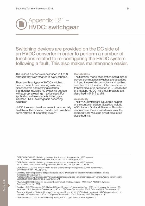
App
endi
x E
Appendix E21 – HVDC: switchgear
The various functions are described in 1, 2, 3, although they won’t feature in every scheme .
There are three types of HVDC switching device: current commutating switches, disconnectors and earthing switches . Standard air insulated AC switching devices with appropriate ratings may be used . For applications where space is limited, gas insulated HVDC switchgear is becoming available .4
HVDC line circuit breakers are not commercially available at the moment, but devices have been demonstrated at laboratory level .5,6,7
CapabilitiesThe function, mode of operation and duties of current commutation switches are described in 1 and those of disconnectors and earthing switches in 2 . Operation of the metallic return transfer breaker is described in 3 . Capabilities of prototype HVDC line circuit breakers are described in 5, 6, 7 and 8 .
AvailabilityThe HVDC switchgear is supplied as part of the converter station . Suppliers include ABB, Alstom Grid and Siemens . Based on manufacturers’ responses to a survey, the availability of HVDC line circuit breakers is described in 8 .
Switching devices are provided on the DC side of an HVDC converter in order to perform a number of functions related to re-configuring the HVDC system following a fault. This also makes maintenance easier.
1 CIGRÉ WG 13/14 .08, ‘Switching devices other than circuit-breakers for HVDC systems, part 1: current commutation switches’, Electra No . 125, Jul 1989, pp 41-55
2 CIGRÉ WG 13/14 .08, ‘Switching devices other than circuit-breakers for HVDC systems, part 2: disconnectors and earthing switches’, Electra No . 135, Apr 1991, pp 32-53
3 CIGRÉ WG 13 .03, ‘The metallic return transfer breaker in high voltage direct current transmission’, Electra No 68, Jan 1980, pp 21-30
4 Siemens, ‘Siemens presents first gas insulated 320kV switchgear for direct current transmission’, (online). (Accessed 24 August 2015) . Available: http://www .siemens .com/press/en/pressrelease/?press=/en/pressrelease/2014/energy/power-transmission/ept201408064 .htm&content()=ET&content()=EM
5 ‘The hybrid HVDC breaker; an innovation breakthrough enabling reliable HVDC grids’, ABB Grid Systems, Technical Paper, Nov 2012
6 Davidson, C C, Whitehouse, R S, Barker, C D, and Dupraz, J-P, ‘A new ultra-fast HVDC circuit breaker for meshed DC networks’, 11th International Conference on AC and DC Power Transmission, 10–12 February 2015, Birmingham, UK
7 Tahata, K, Kamei, K, Yoshida, D, Kono, Y, Yamamoto, R, and Ito, H, ‘HVDC circuit breakers for HVDC applications’, 11th International Conference on AC and DC power Transmission, 10–12 February 2015, Birmingham, UK
8 CIGRÉ WG B4 .52, ‘HVDC Grid Feasibility Study’, Apr 2013, pp 38–44, 77–83, Appendix H
Electricity Ten Year Statement 2015 64
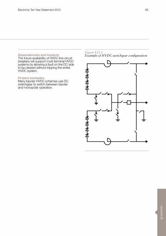
Appendix E
Dependencies and impactsThe future availability of HVDC line circuit breakers will support multi-terminal HVDC systems by allowing a fault on the DC side to be cleared without tripping the entire HVDC system .
Project examplesMany bipolar HVDC schemes use DC switchgear to switch between bipolar and monopolar operation .
Figure E21.1Example of HVDC switchgear configuration
Electricity Ten Year Statement 2015 65
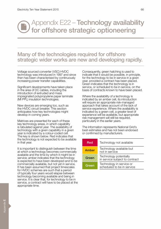
App
endi
x E
Appendix E22 – Technology availability for offshore strategic optioneering
Voltage sourced converter (VSC) HVDC technology was introduced in 1997 and since then has been characterised by continuously increasing power transfer capabilities .
Significant developments have taken place in the area of DC cables, including the introduction of extruded and mass impregnated polypropylene paper laminate (MI PPL) insulation technologies .
New devices are emerging too, such as the HVDC circuit breaker . This section anticipates how key technologies might develop in coming years .
Matrices are presented for each of these key technology areas, in which capability is tabulated against year . The availability of technology with a given capability in a given year is indicated by a colour-coded cell . The key is shown below . Red indicates that the technology is not expected to be available in that year .
It is important to distinguish between the time at which a technology becomes commercially available and the time by which it might be in service; amber indicates that the technology is expected to have been developed and to be commercially available, but not yet in service . It has been assumed that project timescales for HVDC schemes are such that a period of typically four years would elapse between technology becoming available and being in service . It is clear that, for technology to be in service, a contract will have to be placed at the appropriate time .
Consequently, green hatching is used to indicate that it would be possible, in principle, for the technology to be in service in a given year, provided a contract has been placed . Green indicates that the technology is in service, or scheduled to be in service, on the basis of contracts known to have been placed .
Where the availability of a technology is indicated by an amber cell, its introduction will require an appropriate risk-managed approach that takes account of the lack of service experience . Where the availability is indicated by a green cell, a greater level of experience will be available, but appropriate risk management will still be required, particularly in the earlier years .
The information represents National Grid’s best estimates and has not been endorsed or confirmed by manufacturers.
Many of the technologies required for offshore strategic wider works are new and developing rapidly.
Red Technology not available
Amber Technology available but not in service
Technology potentially in service subject to contract
Green Technology in service or scheduled to be in service
Green
Electricity Ten Year Statement 2015 66

Appendix E
HVDC convertersThe expected development in the capability of VSC HVDC technology is illustrated in Table E22 .1 .
Where used with a DC cable circuit, the achievable power transfer capability for the converters will depend on the level of DC voltage permitted by the cable . Current modular multi-level converters are scalable by voltage and could reach the DC voltage level of any foreseeable cable with little development effort . The highest DC voltage for a VSC HVDC system presently in service is 500kV pole-to-ground for the Skagerrak 4 project1, which uses MI cables and became operational in 2015 . It is assumed that converters will continue to reach the level of DC voltage permitted by the cables as the technology develops .
The level of DC current achievable is determined by the IGBT modules used in the converter valves . The interconnection between France and Spain2, commissioning in 2015, comprises two HVDC links with a power transfer capacity of 1,000MW each and operating at ±320kV, representing a DC current of more than 1,563A .
The Caithness Moray HVDC Link will have a power rating of 1200MW at ±320kV, representing a d .c . current of more than 1875A .3 IGBT modules permitting DC currents of 2,000A are expected to be available for contracts placed in 2016 .4 Achievement of higher DC currents may be possible in future years with further development of semiconductor devices and materials, but would depend on the availability of cables able to carry these levels of current .
Current sourced converter (CSC) technology has developed to a stage where it could match the voltage and current ratings of any cable or overhead line with which it might be used on the GB transmission system .
For example, the Southern Hami – Zhengzhou HVDC link in China operates at ±800kV DC and with a power transfer capability of 8,000MW .5 No figure is given in the present document to illustrate the future development of CSC HVDC converter technology as it is unlikely to represent the limit on the capability of the system in which it is used within the GB transmission system .
E22.1 – Technology availability (components)
2016 2017 2018 2019 2020 2021 2022 2023 2024 2025 2030 20351563 A G G G G G G G G G G G G1875 A A A A A2000 A R A A A A
Key Technology not availableTechnology available but not in serviceTechnology potentially in service subject to contractTechnology in service or scheduled to be in service
G G G G G G G GG G G G G G G
Table E22.1Voltage sourced converters
Footnotes: see pages 78–79
Electricity Ten Year Statement 2015 67

App
endi
x E
HVDC cablesThe expected availability of HVDC cables with extruded insulation is illustrated in Table E22 .2 .
Extruded cables with a DC voltage of 320kV are in service .6 The highest DC voltage for extruded cables currently on order is 400kV for the Nemo Link interconnector .7 A 525kV extruded DC cable system has been qualified.8
With regard to cable development, the CIGRÉ Ref . 533 published in April 2013 included the results of a questionnaire that had been sent to cable manufacturers .9 One respondent indicated that extruded cables for a DC voltage of 600kV would be available within the next 5 years and 750kV within 10 to 15 years; another stated that extruded cable with a DC voltage of 500kV has been developed in Japan . Other manufacturers were also pursuing developments, but tended to be less specific and more cautious with regard to their plans . In their review report published in June 2013, SKM expressed the view that 500kV extruded cables would be available in the next 2-3 years .4
Table E22 .2 takes into consideration the range of forecasts for the development of extruded cables together with a judgement of the likely timescales for development and testing . The expected availability of HVDC cables with MI and MI PPL insulation is illustrated in Table E22 .3 .
MI cables are more established than extruded cables and can achieve higher voltages at present . MI cables at 500kV are in service on the SAPEI HVDC link between Sardinia and Italy .10 The highest DC voltage for cables currently on order is 600kV for the Western HVDC Link, scheduled to enter service in 2017 .11
The questionnaire reported in the April 2013 CIGRÉ Ref . 533 also addressed the forecast development of MI cables .9 In his response, one respondent indicated that MI cables for a DC voltage of 750kV would be available within 10 to 15 years . Another expected to achieve a voltage level of 800kV ‘in the next few years’ .
Table E22 .3 takes into consideration the range of forecasts for the development of MI and MI PPL cables, together with a judgement of likely timescales for development and testing .
MI cables may be used with CSC converters, which will be able to match the current-carrying capability of the cable . The expected availability of MI cables according to current-carrying capability is illustrated in Table E22 .4 . The cables of the Western HVDC Link will achieve a current-carrying capability in excess of 1,800A .11 It has been assumed that, with some development, an increase in current-carrying capability to 2,000A in the early years would be challenging but possible . This is consistent with the results of the CIGRÉ Ref . 533 survey .9 This does not represent a fundamental limit because the conductor cross section could be increased at the cost of more difficult cable installation .
Footnotes: see pages 78–79
Appendix E22 – Technology availability for offshore strategic optioneering
Electricity Ten Year Statement 2015 68
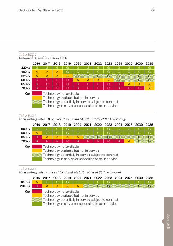
Appendix E
Table E22.2Extruded DC cable at 70 to 90˚C
2016 2017 2018 2019 2020 2021 2022 2023 2024 2025 2030 2035320kV G G G G G G G G G G G G400kV A A A G G G G G G G G G525kV A A A A600kV R R R R A A A A650kV R R R R R R R R R A A A700kV R R R R R R R R R R R A
Key Technology not availableTechnology available but not in serviceTechnology potentially in service subject to contractTechnology in service or scheduled to be in service
G G G G G G G GG G G G
Table E22.3Mass impregnated DC cables at 55˚C and MIPPL cables at 80˚C – Voltage
2016 2017 2018 2019 2020 2021 2022 2023 2024 2025 2030 2035500kV G G G G G G G G G G G G600kV A G G G G G G G G G G G650kV R A A A A700kV R R R R R R R R R A
Key Technology not availableTechnology available but not in serviceTechnology potentially in service subject to contractTechnology in service or scheduled to be in service
G G G G G G GG G
Table E22.4Mass impregnated cables at 55˚C and MIPPL cables at 80˚C – Current
2016 2017 2018 2019 2020 2021 2022 2023 2024 2025 2030 20351876 A A G G G G G G G G G G G2000 A R A A A A
Key Technology not availableTechnology available but not in serviceTechnology potentially in service subject to contractTechnology in service or scheduled to be in service
G G G G G G G
Electricity Ten Year Statement 2015 69
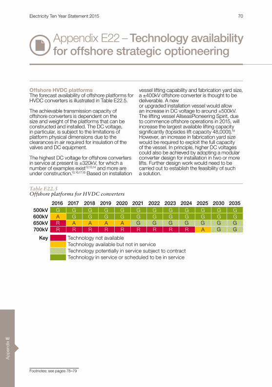
App
endi
x E
Table E22.5Offshore platforms for HVDC converters
Offshore HVDC platformsThe forecast availability of offshore platforms for HVDC converters is illustrated in Table E22 .5 .
The achievable transmission capacity of offshore converters is dependent on the size and weight of the platforms that can be constructed and installed . The DC voltage, in particular, is subject to the limitations of platform physical dimensions due to the clearances in air required for insulation of the valves and DC equipment .
The highest DC voltage for offshore converters in service at present is ±320kV, for which a number of examples exist12,13,14 and more are under construction .15,16,17,18 Based on installation
vessel lifting capability and fabrication yard size, a ±400kV offshore converter is thought to be deliverable . A new or upgraded installation vessel would allow an increase in DC voltage to around ±500kV . The lifting vessel AllseasPioneering Spirit, due to commence offshore operations in 2015, will increase the largest available lifting capacity significantly (topsides lift capacity 48,000t).19 However, an increase in fabrication yard size would be required to exploit the full capacity of the vessel . In principle, higher DC voltages could also be achieved by adopting a modular converter design for installation in two or more lifts . Further design work would need to be carried out to establish the feasibility of such a solution .
2016 2017 2018 2019 2020 2021 2022 2023 2024 2025 2030 2035500kV G G G G G G G G G G G G600kV A G G G G G G G G G G G650kV R A A A A700kV R R R R R R R R R A
Key Technology not availableTechnology available but not in serviceTechnology potentially in service subject to contractTechnology in service or scheduled to be in service
G G G G G G GG G
Footnotes: see pages 78–79
Appendix E22 – Technology availability for offshore strategic optioneering
Electricity Ten Year Statement 2015 70
Appendix E
The forecast capability of systems comprising HVDC converters and DC cables is determined by the forecast capability of the component technologies illustrated in the previous figures. The achievable MVA rating in a given year is determined by the DC current and DC voltage permitted by the component technologies .
The availability of a given MVA rating in a given year is determined by whichever of the component technologies has the lowest availability . Many combinations of component DC current and DC voltage are possible; results are shown in the figures where an increase in DC current, DC voltage or both allows a higher MVA rating for the system to be achieved . If a given MVA rating is available in a given year, it follows that any lower value of MVA rating will also be available . The combination of DC current and DC voltage permitting the increase in MVA rating is indicated in the figures.
The maximum real power transmissible by the system may be less than the MVA rating, depending on requirements for converters to provide reactive power . For line commutated converters, reactive compensation plant is always provided as part of the scheme .
HVDC systems with converters located onshoreThe availability of HVDC systems where VSC converters located onshore are used with extruded cables is illustrated in Table E22 .6 .
The interconnector between France and Spain, commissioning in 2015, will achieve a power transfer capability of 1000MW .2 The Caithness Moray project will achieve a power transfer capability of 1200MW .3 The forecast increases in the DC current and voltage levels of the converters and cables allow a continuing increase in the achievable MVA rating . Table E22 .6 indicates that a 2000MVA solution would be commercially available by 2017 and might potentially be in service by 2021 .
The availability of HVDC systems where VSC converters located onshore are used with mass impregnated cables is illustrated in Table E22 .7 .
The greater DC voltage permitted by mass impregnated cables compared with extruded cables allows greater MVA ratings to be achieved in a given year . The Skagerrak 4 project1, commissioned in 2015, combines VSC converters with MI cables to achieve a power transfer capability of 700MW with a single pole operating at 500kV DC . Consequently, although Skagerrak 4 is a monopole, the technology would allow 1400MVA to be achieved with a bipole operating at ±500kV . However, the DC current of around 1400A is within present limits and, in principle, 1563MVA or more could be achieved with existing technology . The expected developments in converter current and cable voltage indicate that a 2000MVA solution might be in service by 2019 .
The availability of systems where line commutated converters located onshore are used with mass impregnated cables is illustrated in Table E22 .8 .
In contrast to systems using voltage-sourced converters, the DC current will not be limited by the capability of the converter but by that of the cables . A solution with a power transfer capability of 2250MW will be in service in 2017 on commissioning of the Western HVDC Link .11 Further increases will be possible, largely enabled by increases in cable DC voltage . However, beyond 2017 the DC current capability of the VSC is expected to have converged with that of the cables . From this point on, the power transfer capability of HVDC systems using line commutated converters will no longer be greater than that achievable with VSCs for cable applications .
E22.2 – Technology availability (systems)
Footnotes: see pages 78–79
Electricity Ten Year Statement 2015 71

App
endi
x E
Table E22.6HVDC systems comprising VSCs and extruded cables
Table E22.7HVDC systems comprising VSCs and mass impregnated cables
Table E22.8HVDC systems comprising line commutated converters and mass impregnated cables
2016 2017 2018 2019 2020 2021 2022 2023 2024 2025 2030 20351000MVA G G G G G G G G G G G G 320kV 1563A1200MVA A A A G G G G G G G G G 320kV 1875A1970MVA A A A A 525kV 1875A2100MVA R A A A A 525kV 2000A2400MVA R R R R A A A A 600kV 2000A2600MVA R R R R R R R R R A A A 650kV 2000A2800MVA R R R R R R R R R R R A 700kV 2000A
Key Technology not availableTechnology available but not in serviceTechnology potentially in service subject to contractTechnology in service or scheduled to be in service
G G G G G G G GG G G G G G G
G G G G
2016 2017 2018 2019 2020 2021 2022 2023 2024 2025 2030 20351400MVA G G G G G G G G G G G G 500kV 1400A2250MVA A A A A 600kV 1875A2600MVA R A A A A 650kV 2000A2800MVA R R R R R A A A A 700kV 2000A3000MVA R R R R R R R R R A A A 750kV 2000A
Key Technology not availableTechnology available but not in serviceTechnology potentially in service subject to contractTechnology in service or scheduled to be in service
G G G G G G G GG G G G G G G
G G G
2016 2017 2018 2019 2020 2021 2022 2023 2024 2025 2030 20352250MVA A G G G G G G G G G G G 600kV 1875A2600MVA R A A A A 650kV 2000A2800MVA R R R R R A A A A 700kV 2000A3000MVA R R R R R R R R R A A A 750kV 2000A
Key Technology not availableTechnology available but not in serviceTechnology potentially in service subject to contractTechnology in service or scheduled to be in service
G G G G G G GG G G
Appendix E22 – Technology availability for offshore strategic optioneering
Electricity Ten Year Statement 2015 72
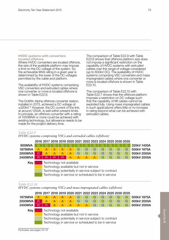
Appendix E
Table E22.9HVDC systems comprising VSCs and extruded cables (offshore)
Table E22.10HVDC systems comprising VSCs and mass impregnated cables (offshore)
HVDC systems with converters located offshoreWhere HVDC converters are located offshore, the size of the available platform may impose a limit on the DC voltage of the system . So the achievable MVA rating in a given year is determined by the lower of the DC voltages permitted by the cable and platform .
The availability of HVDC systems comprising VSC converters and extruded cables where one converter or more is located offshore is shown in Table E22 .9 .
The DolWin Alpha offshore converter station, installed in 2013, achieved a DC voltage of ±320kV .14 However, the DC current of the link, at around 1250A, is well within present limits . In principle, an offshore converter with a rating of 1000MVA or more could be achieved with existing technology, but allowance needs to be made for the project delivery time .
The comparison of Table E22 .9 with Table E22 .6 shows that offshore platform size does not impose a significant restriction on the capability of HVDC systems with extruded cables over the range of voltage considered (up to 600kV DC) . The availability of HVDC systems comprising VSC converters and mass impregnated cables where one converter or more is located offshore is shown in Table E22 .10 .
The comparison of Table E22 .10 with Table E22 .7 shows that the offshore platform imposes a restriction on DC voltage such that the capability of MI cables cannot be exploited fully . Using mass impregnated cables in such applications offers little or no increase in rating beyond what can be achieved with extruded cables .
2016 2017 2018 2019 2020 2021 2022 2023 2024 2025 2030 2035900MVA G G G G G G G G G G G G 320kV 1400A1875MVA A A A A A 500kV 1875A2000MVA R A A A A 500kV 2000A2400MVA R R R R A A A A 600kV 2000A
Key Technology not availableTechnology available but not in serviceTechnology potentially in service subject to contractTechnology in service or scheduled to be in service
G G G G G G GG G G G G G G
G G G G
2016 2017 2018 2019 2020 2021 2022 2023 2024 2025 2030 20351875MVA A A A A A 500kV 1875A2000MVA R A A A A 500kV 2000A2400MVA R R A A A A A 600kV 2000A
Key Technology not availableTechnology available but not in serviceTechnology potentially in service subject to contractTechnology in service or scheduled to be in service
G G G G G G GG G G G G G G
G G G G G
Footnotes: see pages 78–79
Electricity Ten Year Statement 2015 73
App
endi
x E
HVDC protection and controlThe availability of control and protection for VSC HVDC systems is illustrated in Table E22.11. The figure shows the expected availability of protection and control VSC HVDC systems of increasing complexity (two-terminal systems, multi-terminal systems and multi-terminal systems with multi-vendor interoperability) .
For two-terminal, ‘point-to-point’ VSC HVDC schemes – including connections to wind generation – protection and control are well established and the technology has been in service since 1997 .20,21
Protection and control for multi-terminal VSC HVDC schemes are less well established . The world’s first multi-terminal VSC HVDC systems have recently been commissioned .
The first three-terminal VSC HVDC system was commissioned at Nan’ao in China in December 2013 [22] . SEPRI (Electric Power Research Institute, China Southern Power Grid) had technical responsibility for the project, which involved three control and protection suppliers .
The first five-terminal VSC HVDC system was commissioned in Zhoushan in China in June 2014 .23 The control and protection system for the converter stations at each terminal was offered by a single supplier .
A further development in protection and control technology for VSC HVDC systems is the achievement of multi-vendor interoperability . This means that a VSC HVDC system may be extended in the future by the connection of further terminals without being restricted to the original supplier .
A contract was awarded for a VSC HVDC connection forming the first phase of Sweden’s South West Link in January 2012 . The scheme has been designed to permit future extension by the connection of additional terminals to form a multi-terminal link .24
The Atlantic Wind Connection in the US is more complex . The project is planned to be built in stages to form an offshore multi-terminal VSC HVDC network spanning the east coast from New Jersey to Virginia .25 When completed, it will facilitate the connection of up to 6000MW of offshore wind generation while reinforcing the onshore transmission system .
No standards currently exist for the control and protection of multi-terminal VSC HVDC systems . Working Bodies within CIGRÉ and CENELEC are addressing the issues of control and protection for multi-terminal HVDC systems and it seems likely that standard solutions will be developed within the next few years .
So when it comes to protection and control technology, there is service experience for two-terminal VSC HVDC systems . For multi-terminal applications, the technology is commercially available and has recently been put into service . It would be possible for a multi-vendor interoperability solution to be in service by 2018, but no contracts are known to have been placed at present .
It should be emphasised that the interaction of any HVDC link with the AC system or systems to which it is connected may raise protection and control issues that are not covered by any of the above and further guidance is needed . The requirements for each scheme will need to be assessed and the risks evaluated .
Footnotes: see pages 78–79
Appendix E22 – Technology availability for offshore strategic optioneering
Electricity Ten Year Statement 2015 74

Appendix E
Table E22.11HVDC protection and control
Table E22.12HVDC circuit breaker
HVDC circuit breakerThe expected availability of the HVDC circuit-breaker is illustrated in Table E22 .12 .
A hybrid HVDC circuit breaker designed for a rated voltage of 320kV, a rated current of 2kA and a current-breaking capability of 9kA has been verified in the laboratory.26 Allowing for project timescales, the device might be in service by 2020 . Other HVDC circuit breaker prototypes have been demonstrated .27,28
The manufacturer of the first-mentioned HVDC circuit breaker envisages that the next generation of semiconductor devices will allow an increase in the breaking current to 16kA .26 The increase in rated voltage that this
would facilitate depends on the current limiting reactor that is used with the HVDC breaker, which may itself be subject to limitation in size . For the purposes of Table E22 .12, it has been estimated that a rated voltage in excess of 550kV would be achievable and that such a device might be in service by 2021 .
The above is consistent with the results of a questionnaire sent to prospective HVDC breaker manufacturers and published in CIGRÉ Ref . 533 in April 20139, where one respondent indicated that HVDC breakers operating at >500kV with a breaking capacity of 16kA would be available within five years. Another indicated that a >500kV device would be available within 10 years .
2016
2017
2018
2019
2020
2021
2022
2023
2024
2025
2030
2035
Control (two-terminal) G G G G G G G G G G G GProtection (two-terminal) G G G G G G G G G G G G
Control (multi-terminal) G G G G G G G G G G G GProtection (multi-terminal) G G G G G G G G G G G G
Control (multi-terminal, multi vendor) A A A AProtection (multi-terminal) A A A A
Key Technology not availableTechnology available but not in serviceTechnology potentially in service subject to contractTechnology in service or scheduled to be in service
G G G G G G G GG G G G G G G G
2016 2017 2018 2019 2020 2021 2022 2023 2024 2025 2030 2035A A A A 320kV 2000AR A A A A 550kV 2000A
Key Technology not availableTechnology available but not in serviceTechnology potentially in service subject to contractTechnology in service or scheduled to be in service
G G G G G G G GG G G G G G G
Footnotes: see pages 78–79
Electricity Ten Year Statement 2015 75
App
endi
x E
AC cablesThe global proliferation of offshore wind farms has resulted in rapid development of AC submarine technology . Single-core (1c) and three-core (3c) solutions have been in service for decades, using fluid-filled (1c) and paper and oil individual lead sheaths (3c) at a wide range of power and voltage applications . Extruded cross linked polyethylene (XLPE) cable types have formed the bulk of the AC submarine cable market for the last few years .29
Three-core cable designs offer a good solution to the problems of losses in the armour because the three differently phased magnetic fields in trefoil formation largely cancel magnetic fields. This in turn reduces circulating currents in the armour, allowing the use of more conventional (lower cost) steel wire armouring (SWA) .
The trefoil formation does have some thermal disadvantages, but this is helped to some extent by the generally lower ambient temperatures in water (compared to land) .
Consolidating three cores into a single cable means that a single installation run is required . However, the material costs are generally greater than the costs of three individual cables, so for shorter distances, single-core solutions may prove more cost-effective .
The availability of three-core AC submarine cables is shown in Table E22 .13 .
Single cables with three cores of up to 230mm diameter and weights of nearly 100kg/m have been built at voltages up to 245kV30, with a 420kV cable rated at 500MW on order .31
Conductor sizes of more than 1000mm² are believed to be possible .32 A cable length of just over 100km has been achieved at a voltage of
132kV .33 Unfortunately the increasing capacitive effects disadvantage higher voltage cables with the economic range of 400kV and higher voltage cables reducing to not much more than 20km . A good compromise between power delivery and transmission distance can be achieved by using a voltage of 200kV . However, as yet there is no voltage standardisation within the offshore industry and 245kV and 275kV solutions are also possible .
The technology is likely to be limited by the capability of factory extrusion lines to manufacture the larger sized common over sheaths and armouring required for increasing conductor sizes . Onshore and offshore handling difficulties will also play a role because weights beyond 100kg/m could prove challenging. Lighter “filler” materials with better thermal properties could bring benefits as the technology matures .
Single-core solutions benefit from the improved thermal characteristics associated with flat configurations and increased spacing between cores (as well as the differential between sea and land temperatures) . However, they are affected by unbalanced magnetic fields – this problem is normally resolved by using cross-bonding on land, (which involves conductive armours to reduce circulating currents and armour losses) . These can often be of almost the same cross section as the conductors, so material costs can be high compared to the equivalent land cables and three installation runs will probably be needed . However, the single-core designs are free to use much larger conductor sizes than 3c cables (theoretically up to 3000mm²), so very large power transfers are possible .34
The availability of single-core AC submarine cables is shown in Table E22 .14 .
Footnotes: see pages 78–79
Appendix E22 – Technology availability for offshore strategic optioneering
Electricity Ten Year Statement 2015 76

Appendix E
Table E22.13Three-core AC submarine cables
Table E22.14Single-core AC submarine cables
HVDC gas-insulated switchgear (GIS)Gas-insulated switchgear (GIS) is a compact alternative to conventional air-insulated switchgear . It has been widely used in AC systems for a number of years in applications where space is limited, such as substations in urban areas, but it has not yet been widely applied to HVDC systems . Following developments in insulating materials, however, a 320kV GIS for HVDC applications has recently been introduced .35 In principle, it would be possible to develop DC GIS for higher voltages, but there is little on which to base the timescales for development .
Offshore platforms for AC substations Offshore AC substations are significantly smaller in size and weight than those required for HVDC converter stations and the required power transfer capacity can usually be achieved without great difficulty.
ConclusionsForecasts of the likely availability of key technologies for strategic wider works are based on state-of-the art and, wherever
possible, on known developments . Overall, growing trends in power transfer capability and the functionality of VSC HVDC links are likely to play an increasingly important role in future years as the British transmission system accommodates increasing volumes of renewable generation . Anticipated developments include:nAn increase in DC current of VSC HVDC
converters as higher power semiconductor devices become available
nA continuing increase in the DC voltage of extruded and mass impregnated DC cables
nDevelopments in the technology of offshore platforms for HVDC converters allowing higher power transfer capabilities
nThe application of multi-terminal VSC HVDC systems
nThe achievement of interoperability between different suppliers’ HVDC equipment
nIntroduction of the HVDC circuit-breakernIntroduction of DC GIS .
These forecasts intend to provide guidance of what technology will be available within the timescale of individual projects .
2016 2017 2018 2019 2020 2021 2022 2023 2024 2025 2030 2035500MW G G G G G G G G G G G G600MW A A A A700MW R R R A A A A
Key Technology not availableTechnology available but not in serviceTechnology potentially in service subject to contractTechnology in service or scheduled to be in service
G G G G G G G GG G G G G
2016 2017 2018 2019 2020 2021 2022 2023 2024 2025 2030 20351000MW G G G G G G G G G G G G1200MW A A A A1300MW A A A A A A A
Key Technology not availableTechnology available but not in serviceTechnology potentially in service subject to contractTechnology in service or scheduled to be in service
G G G G G G G GG G G G G
Electricity Ten Year Statement 2015 77

App
endi
x E
(1) ABB, ABB sets world record in HVDC Light voltage level (online) . (Accessed: 19 August 2015) . Available: http://www .abb .com/cawp/seitp202/e0311ee675bb33b3c1257dcb00300a8c .aspx
(2) Siemens, Siemens puts converter stations of HVDC link between France and Spain into operation (online) . (Accessed 19 August 2015) . Available: http://www .siemens .com/press/en/events/2015/energymanagement/2015-04-Inelfe .php?content%5B%5D=EM
(3) ABB, ABB wins $800 million order for Scotland’s Caithness-Moray subsea power link (online) . (Accessed: 19 August 2015) . Available: http://www .abb .com/cawp/seitp202/d975999eef89be7bc1257d49005d1863 .aspx
(4) Sinclair Knight Merz (SKM), Review of Worldwide Voltage Source Converter (VSC) High Voltage Direct Current (HVDC) Technology Installations (online) . (Accessed: 27 August 2015) . Available: https://www .ofgem .gov .uk/publications-and-updates/skm-review-worldwide-voltage-source-converter-vsc-high-voltage-direct-current-hvdc-technology-installations
(5) State Grid Corporation of China, Southern Hami-Zhengzhou ±800kV UHVDC Transmission Project Second Xinjiang-Northwest Main Grid 750kV HVDC Transmission Line Start Construction to Build the Silk Road of Electricity Connecting the Western Frontier with the Central Plains (online) . (Accessed: 19 August 2015) . Available: http://www .sgcc .com .cn/ywlm/mediacenter/corporatenews/05/272889 .shtml
(6) Prysmian Group, Successful commissioning of SylWin1 HVDC grid connection (online) . (7) NEMO LINK, NEMO LINK announces €500m contracts to build the first interconnector between GB and Belgium (online).
(Accessed: 19 August 2015) . Available: http://www .nemo-link .com/latest-news/
(8) Gustafsson, A, et al, The new 525kV extruded HVDC cable system, Technical Paper, ABB Grid Systems, August 2014 .(9) CIGRÉ WG B4 .52, HVDC grid feasibility study, CIGRÉ Ref .533, April 2013 .(10) Rendina, R, et al, The realisation and commissioning of the ±500kV 1000MW HVDC link Sardinia Island – Italian Peninsular
(SAPEI), Paper B1-101, CIGRÉ 2012 .(11) Prysmian Group, Prysmian secures the highest value cable project ever awarded, worth €800 million (online) .
(Accessed: 27 August 2015) . Available: http://investoren.prysmian.com/phoenix.zhtml?c=211070&p=RssLanding_pf&cat=news&id=1661739
(12) Siemens, Fact Sheet SylWin1 HVDC Platform Status: April 2015 (online) . (Accessed: 20 August 2015) . Available: http://www .siemens .com/press/pool/de/feature/2013/energy/2013-08-x-win/factsheet-sylwin1-e .pdf
(13) Siemens, Siemens hands over fourth North Sea grid connection HelWin2 to TenneT (online) . (Accessed 20 August 2015) . Available: http://www .siemens .com/press/en/pressrelease/?press=/en/pressrelease/2015/energymanagement/pr2015060251emen .htm&content()=EM
(14) ABB, DolWin1 integrates 800 megawatts (MW) of clean energy into the german transmission grid (online) . (Accessed 20 August 2015) . Available: http://new .abb .com/systems/hvdc/references/dolwin1
(15) ABB, ABB positions world’s most powerful offshore converter platform in the North Sea (online) . (Accessed 20 August 2015) . Available: http://new .abb .com/systems/hvdc/references/dolwin2
(16) Alstom, Start of construction for DolWin gamma offshore converter platform (online) . (17) Siemens, Siemens receives major order for BorWin3 North Sea grid connection from TenneT (online) .
(Accessed 20 August 2015) . Available: http://siemens .com/press/en/pressrelease/?press=/en/pressrelease/2014/energy/power-transmission/et201404036 .htm&content()=ET&content()=EM
(18) Alstom, Alstom HVDC Technology to Power America’s First Offshore Energy Link (online) . (Accessed 20 August 2015) . Available: http://www.alstom.com/press-centre/2013/1/alstom-hvdc-technology-to-power-americas-first-offshore-energy-link/
(19) Allseas, Pioneering Spirit (online) . (Accessed 20 August 2015) . Available: http://www .allseas .com/uk/19/equipment/pieter-schelte .html
(20) Asplund, G, Eriksson, K, and Svensson, K, DC transmission based on VSCs, CIGRÉ SC 14 Colloquium in South Africa 1997 .(21) Skytt, A K, Holmberg, P, and Juhlin, L-E, HVDC Light for connection of wind farms, Second International Workshop on
transmission Networks for Offshore Wind Farms, Stockholm, March 29-30, 2001 .(22) Bathurst, G, and Bordignan, P, Delivery of the Nan’ao multi-terminal VSC-HVDC system, 11th International Conference on AC
and DC Power Transmission, Birmingham, UK, 10-12 February 2015 (23) NR Electric, Zhoushan multi-terminal VSC HVDC project was put into service (online) . (Accessed: 27 August 2015) .
Available: http://www .nrelect .com/news-content-253 .html(24) Alstom, South West Link Balancing the power supply between central and southern Sweden with HVDC (online) .
(Accessed: 20 August 2015) . Available: http://www .alstom .com/Global/OneAlstomPlus/Grid/PDF/Supergrid/SouthWest%20Link%20HVDC%20project .pdf?epslanguage=en-GB
Appendix E22 – Technology availability for offshore strategic optioneering
Electricity Ten Year Statement 2015 78

Appendix E
(25) Atlantic Wind Connection, Atlantic Wind Connection (online) . (Accessed 20 August 2015) . Available: http://www .atlanticwindconnection .com/home
(26) Callavik, M, Blomberg, A, Häfner, J and Jacobson, B, The hybrid HVDC breaker: An innovation breakthrough enabling reliable HVDC grids (online) . (Accessed: 27 August 2015) . Available: http://new .abb .com/docs/default-source/default-document-library/hybrid-hvdc-breaker---an-innovation-breakthrough-for-reliable-hvdc-gridsnov2012finmc20121210_clean.pdf?sfvrsn+2
(27) Davidson, C C, Whitehouse, R S, Barker, C D, and Dupraz, J-P, A new ultra-fast HVDC circuit-breaker for meshed DC networks, 11th International Conference on AC and DC Power Transmission, Birmingham, UK, 10-12 February 2015
(28) Tahata, K, Kamei, K, Yoshida, D Kono, Y, Yamamoto, R, and Ito, H, HVDC circuit-breakers for HVDC grid applications, 11th International Conference on AC and DC Power Transmission, Birmingham, 10-12 February 2015
(29) Worzyk, T, Submarine Power Cables, Springer 2009 .(30) Ontario Power Authority, Wolfe Island Wind Project (197 .8MW) – Wolfe Island (online) . (Accessed: 27 August 2015) .
Available: http://www .powerauthority .on .ca/wind-power/wolfe-island-wind-project-1978-mw-wolfe-island(31) ABB, ABB wins $30 million order for world’s highest voltage three-core AC subsea cable (online) . (Accessed: 27 August 2015) .
Available: http://www .abb .co .uk/cawp/seitp202/cde9d973660941c3c12579a3002ab31e .aspx(32) ABB, XLPE submarine cable systems, (online) . (Accessed 28 August 2015) .
Available: http://library .e .abb .com/public/2fb0094306e48975c125777c00334767/XLPE%20Submarine%20Cable%20Systems%202GM5007%20rev%205 .pdf
(33) ABB, ABB wins $170 million contract for world’s longest high voltage subsea AC cable (online) . (Accessed: 27 August 2015) . Available: http://www .abb .co .uk/cawp/seitp202/d3cdc8eaf205a03cc1257acc002b5c90 .aspx
(34) Nexans, At the core of performance, Offshore Wind China 2010, Bergen, 15 March 2010 (online) . (Accessed: 27 August 2015) . Available: http://www .norway .cn/PageFiles/391359/Nexans%20-%20Olivier%20Angoulevant .pdf
(35) Siemens, Siemens presents first gas insulated 320kV switchgear for direct current transmission, (online). (Accessed 20 August 2015) . Available: http://www .siemens .com/press/en/pressrelease/?press=/en/pressrelease/2014/energy/power-transmission/ept201408064 .htm&content()=ET&content()=EM
Electricity Ten Year Statement 2015 79

App
endi
x E
Appendix E23 – Unit costs
Onshore Equipment Costs
Table E23.1Voltage Sourced Converters
Specifications Cost (£M)800MW–320kV 100–1151000MW–320kV 114–1301200MW–320kV 125–1421800MW–500kV 160–1752200MW–500kV 210–226
Table E23.2Current Sourced Converters
Specifications Cost (£M)1000MW–400kV 117–1322000MW–500kV 133–1483000MW–500kV 170–185
Table E23.3Transformers
Specification Cost (£M)180MVA–132/33/33kV 2 .8–3 .4250MVA–132/33/33kV 3 .1–3 .8250MVA–150/33/33kV 3 .3–4 .0
250MVA–220/33kV 3 .5–4 .0300MVA–220/132kV 3 .7–4 .2
350MVA 3 .8–4 .2
Table E23.4AIS Switchgear Bay
Specification Cost (£M)132kV 0 .7–1 .0275kV 1 .1–1 .4400kV 1 .1–1 .4
Table E23.5Series Compensation
Specifications Cost (£M)400MVA–400kV 4 .0–5 .3
Table E23.6Quadrature Booster
Specifications Cost (£M)2750MVA–400kV 8 .5–10 .3
Table E23.7HVAC GIS Switchgear Bay
Specifications Cost (£M)33kV 0 .3–0 .5150kV 1 .0–1 .2220kV 2 .0–2 .5275kV 2 .4–3 .0400kV 3 .3–3 .8
Table E23.8Shunt Reactors
Specifications Cost (£M)60MVAr–33kV 1 .35–1 .65
100MVAr–220kV 3 .7–4 .5200MVAr–400kV 3 .9–4 .7
Table E23.9Shunt Capacitor Banks
Specifications Cost (£M)100MVAr 5 .8–7 .2200MVAr 7 .8–9 .4
Electricity Ten Year Statement 2015 80

Appendix E
Table E23.10Static VAR Compensators
Specifications Cost (£M)
100MVAr 9 .5–11 .7
200MVAr 13 .1–16 .1
Table E23.11STATCOMs
Specifications Cost (£M)
50MVAr 4 .86–6 .24
100MVAr 15 .2–17 .8
200MVAr 22 .4–26 .44
Electricity Ten Year Statement 2015 81

App
endi
x E
Appendix E23 – Unit costs
Offshore Equipment Costs
Table E23.12Voltage Sourced Converters
Specifications Cost (£M)800MW–320kV 84–941000MW–320kV 110–1251200MW–320kV 157–1661800MW–500kV 175–1852200MW–500kV 217–228
Table E23.13Current Sourced Converters
Specifications Cost (£M)
1000MW–400kV N/A
2000MW–500kV N/A
3000MW–500kV N/A
Table E23.14Transformers
Specification Cost (£M)
180MVA–132/33/33kV 3 .0–3 .3
250MVA–132/33/33kV 3 .3–3 .8
250MVA–150/33/33kV 3 .5–4 .0
250MVA–220/33kV 3 .5–4 .0
300MVA–220/132kV 3 .9–4 .2
350MVA 3 .9–4 .2
Table E23.15HVAC GIS Switchgears
Specifications Cost (£M)
33kV 0 .14–0 .2
150kV 0 .9–1 .2
220kV 2 .3–2 .5
275kV 2 .7–3 .0
400kV 3 .6–4 .1
Table E23.16Shunt Reactors
Specifications Cost (£M)
60MVAr–33kV 1 .0–1 .3
100MVAr–220kV 3 .8–4 .1
200MVAr–400kV 4 .0–4 .3
Table E23.17Shunt Capacitor Banks
Specifications Cost (£M)
100MVAr 6 .4–6 .6
200MVAr 9 .3–9 .5
Table E23.18Static VAR Compensators
Specifications Cost (£M)
100MVAr 12 .4–12 .6
200MVAr 17 .0–17 .3
Table E23.19STATCOMs
Specifications Cost (£M)
50MVAr 6 .3–6 .7
100MVAr 19 .0–19 .3
200MVAr 28 .5–29 .0
Electricity Ten Year Statement 2015 82

Appendix E
Onshore Cable – Supply
Table E23.20HVDC Mass Impregnated Cables (copper conductor)
Rating per pair of cables 400kV–500kV (£M per km) 500kV–550kV (£M per km)
800MW 0 .330–0 .447 0 .379–0 .5121000MW 0 .395–0 .482 0 .407–0 .5511200MW 0 .415–0 .562 0 .435–0 .5891500MW 0 .478–0 .648 0 .464–0 .6281800MW 0 .522–0 .706 0 .492–0 .6652000MW 0 .649–0 .878 0 .520–0 .7042500MW N/A N/A
Table E23.21HVDC Extruded Cables (copper conductor)
Rating per pair of cables 220kV–320kV (£M per km) 320kV–400kV (£M per km)
600MW 0 .384–0 .457 0 .400–0 .490800MW 0 .475–0 .530 0 .400–0 .4901000MW 0 .560–0 .685 0 .480–0 .5801200MW 0 .616–0 .755 0 .520–0 .6401500MW 0 .650–0 .780 0 .680–0 .8201800MW N/A 0 .700–0 .8502000MW N/A N/A
Table E23.22HVAC 3 Core Cables (copper conductor)
Rating persingle cable
150kV (£M per km)
220kV (£M per km)
150MW 0 .213–0 .260 0 .270–0 .325200MW 0 .300–0 .370 0 .270–0 .325250MW 0 .365–0 .444 0 .330–0 .402300MW 0 .426–0 .522 0 .360–0 .442350MW 0 .426–0 .522 0 .444–0 .530400MW 0 .426–0 .522 0 .537–0 .656
Electricity Ten Year Statement 2015 83
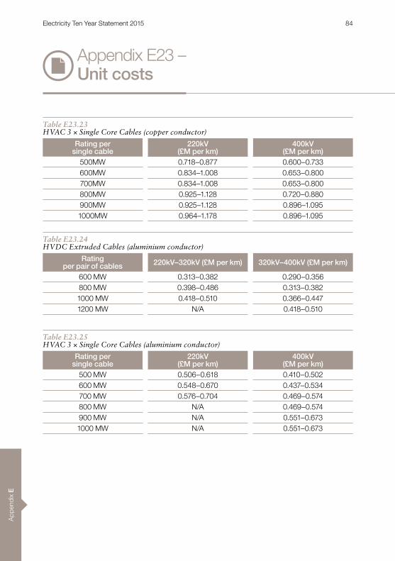
App
endi
x E
Appendix E23 – Unit costs
Table E23.23HVAC 3 × Single Core Cables (copper conductor)
Rating persingle cable
220kV (£M per km)
400kV (£M per km)
500MW 0 .718–0 .877 0 .600–0 .733600MW 0 .834–1 .008 0 .653–0 .800700MW 0 .834–1 .008 0 .653–0 .800800MW 0 .925–1 .128 0 .720–0 .880900MW 0 .925–1 .128 0 .896–1 .0951000MW 0 .964–1 .178 0 .896–1 .095
Table E23.24HVDC Extruded Cables (aluminium conductor)
Rating per pair of cables 220kV–320kV (£M per km) 320kV–400kV (£M per km)
600 MW 0 .313–0 .382 0 .290–0 .356800 MW 0 .398–0 .486 0 .313–0 .3821000 MW 0 .418–0 .510 0 .366–0 .4471200 MW N/A 0 .418–0 .510
Table E23.25HVAC 3 × Single Core Cables (aluminium conductor)
Rating persingle cable
220kV (£M per km)
400kV (£M per km)
500 MW 0 .506–0 .618 0 .410–0 .502600 MW 0 .548–0 .670 0 .437–0 .534700 MW 0 .576–0 .704 0 .469–0 .574800 MW N/A 0 .469–0 .574900 MW N/A 0 .551–0 .6731000 MW N/A 0 .551–0 .673
Electricity Ten Year Statement 2015 84

Appendix E
Onshore Cable – Installation
Table E23.26HVDC Mass Impregnated Cables
Rating per pair of cables 400kV–500kV (£M per km) 500kV–550kV (£M per km)
800MW 0 .4–0 .65 0 .4–0 .651000MW 0 .4–0 .65 0 .4–0 .651200MW 0 .4–0 .65 0 .4–0 .651500MW 0 .4–0 .65 0 .4–0 .651800MW N/A N/A2000MW N/A N/A2500MW N/A N/A
Table E23.27HVDC Extruded Cables
Rating per pair of cables 220kV–320kV (£M per km) 320kV–400kV (£M per km)
600MW 0 .4–0 .65 0 .4–0 .65800MW 0 .4–0 .65 0 .4–0 .651000MW 0 .4–0 .65 0 .4–0 .651200MW 0 .4–0 .65 0 .4–0 .651500MW N/A N/A1800MW N/A N/A
Table E23.28HVAC 3 × Single Core Cables
Rating persingle cable
220kV (£M per km)
400kV (£M per km)
500MW 0 .58–0 .95 0 .58–0 .95600MW 0 .58–0 .95 0 .58–0 .95700MW 0 .58–0 .95 0 .58–0 .95800MW 0 .58–0 .95 0 .58–0 .95900MW 0 .58–0 .95 0 .58–0 .951000MW 0 .77–1 .17 0 .58–0 .95
Electricity Ten Year Statement 2015 85

App
endi
x E
Table E23.29Overhead lines
MVA Rating/Circuit 132kV (£M/ route) 275kV (£M/ route) 400kV (£M/ route)
1000MW 1 .5–1 .8 1 .0–1 .4 1 .0–1 .5
2000MW N/A 1 .5–1 .7 1 .5–1 .93000MW N/A N/A 1 .5–1 .94000MW N/A N/A 2 .0–2 .6
Appendix E23 – Unit costs
Electricity Ten Year Statement 2015 86

Appendix E
Offshore Cable – Supply
Table E23.30HVDC Mass Impregnated Cables (copper conductor)
Rating per pair of cables 400kV–500kV (£M per km) 500kV–550kV (£M per km)
800MW 0 .330–0 .447 0 .379–0 .5121000MW 0 .395–0 .482 0 .407–0 .5511200MW 0 .415–0 .562 0 .435–0 .5891500MW 0 .478–0 .648 0 .464–0 .6281800MW 0 .522–0 .706 0 .492–0 .6652000MW 0 .649–0 .878 0 .522–0 .7042500MW N/A N/A
Table E23.31HVDC Extruded Cables (copper conductor)
Rating per pair of cables 220kV–320kV (£M per km) 320kV–400kV (£M per km)
600MW 0 .384–0 .499 0 .340–0 .550800MW 0 .482–0 .560 0 .400–0 .5501000MW 0 .610–0 .720 0 .460–0 .6401200MW 0 .826–0 .875 0 .632–0 .6901500MW N/A 0 .800–0 .8751800MW N/A 0 .898–1 .0322000MW N/A N/A
Table E23.32HVAC 3 Core Cables (copper conductor)
Rating persingle cable
150kV (£M per km)
220kV (£M per km)
150MW 0 .254–0 .311 0 .320–0 .390200MW 0 .360–0 .440 0 .320–0 .390250MW 0 .433–0 .530 0 .394–0 .482300MW 0 .508–0 .620 0 .433–0 .530350MW 0 .508–0 .620 0 .537–0 .657400MW 0 .508–0 .620 0 .641–0 .784
Electricity Ten Year Statement 2015 87
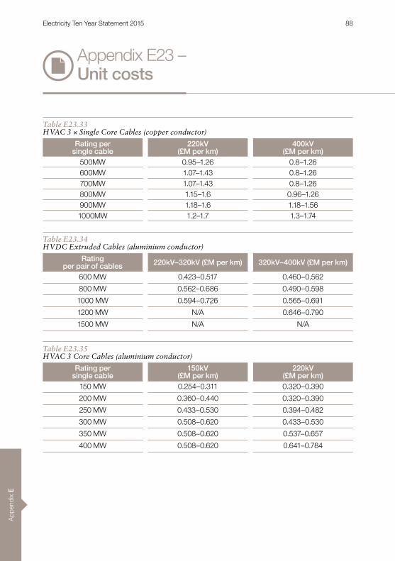
App
endi
x E
Appendix E23 – Unit costs
Table E23.33HVAC 3 × Single Core Cables (copper conductor)
Rating per single cable
220kV (£M per km)
400kV (£M per km)
500MW 0 .95–1 .26 0 .8–1 .26600MW 1 .07–1 .43 0 .8–1 .26700MW 1 .07–1 .43 0 .8–1 .26800MW 1 .15–1 .6 0 .96–1 .26900MW 1 .18–1 .6 1 .18–1 .561000MW 1 .2–1 .7 1 .3–1 .74
Table E23.34HVDC Extruded Cables (aluminium conductor)
Rating per pair of cables 220kV–320kV (£M per km) 320kV–400kV (£M per km)
600 MW 0 .423–0 .517 0 .460–0 .562
800 MW 0 .562–0 .686 0 .490–0 .598
1000 MW 0 .594–0 .726 0 .565–0 .691
1200 MW N/A 0 .646–0 .790
1500 MW N/A N/A
Table E23.35HVAC 3 Core Cables (aluminium conductor)
Rating persingle cable
150kV (£M per km)
220kV (£M per km)
150 MW 0 .254–0 .311 0 .320–0 .390
200 MW 0 .360–0 .440 0 .320–0 .390
250 MW 0 .433–0 .530 0 .394–0 .482
300 MW 0 .508–0 .620 0 .433–0 .530
350 MW 0 .508–0 .620 0 .537–0 .657
400 MW 0 .508–0 .620 0 .641–0 .784
Electricity Ten Year Statement 2015 88
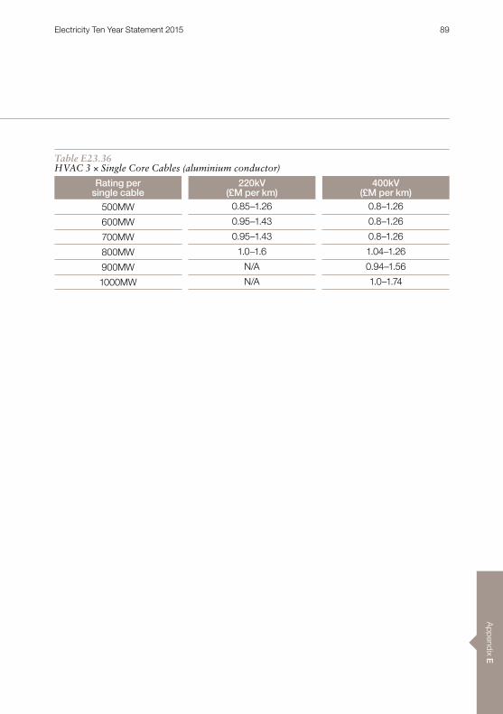
Appendix E
Table E23.36HVAC 3 × Single Core Cables (aluminium conductor)
Rating per single cable
220kV (£M per km)
400kV (£M per km)
500MW 0 .85–1 .26 0 .8–1 .26
600MW 0 .95–1 .43 0 .8–1 .26
700MW 0 .95–1 .43 0 .8–1 .26
800MW 1 .0–1 .6 1 .04–1 .26
900MW N/A 0 .94–1 .56
1000MW N/A 1 .0–1 .74
Electricity Ten Year Statement 2015 89

App
endi
x E
Appendix E23 – Unit costs
Offshore Cable – Installation
Table E23.37
Installation Type £M/kmSingle cable, single trench, single core 0 .3–0 .7
Twin cable, single trench, single core 0 .5–1 .2
2 single cables; 2 trenches, single core, 10M apart 0 .53–1 .2
Single cable, single trench, three core 0 .33–1 .25
2 single cables; 2 trenches, three core, 10M apart 1 .1–2 .3
Table E23.38
Installation Additional Costs CostVessel de/mobilisation 0 .25 £MHDD 1 .3 £M/kmPipeline/cable crossing 1 .3 £M/kmDredging 3 £M/kmGrounding barge for shallow waters 5–10 £M
Electricity Ten Year Statement 2015 90
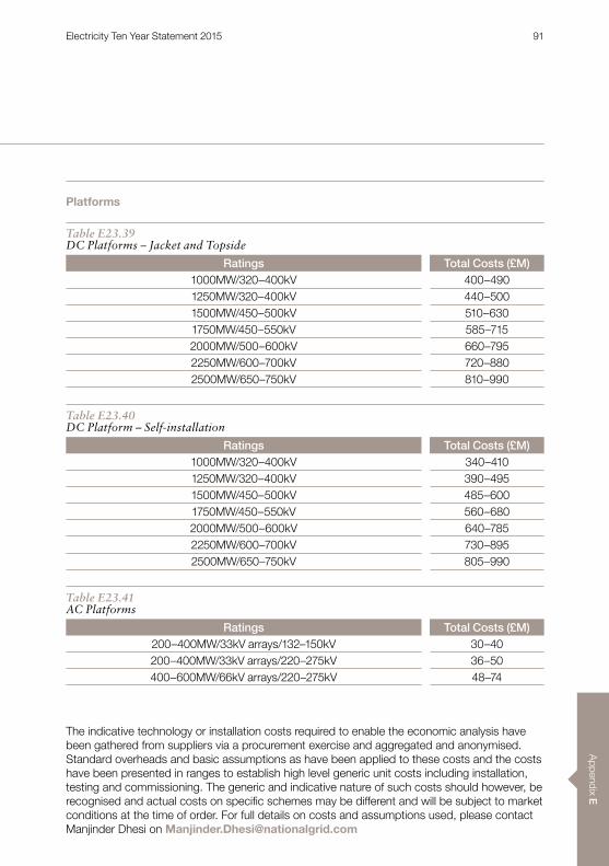
Appendix E
Platforms
The indicative technology or installation costs required to enable the economic analysis have been gathered from suppliers via a procurement exercise and aggregated and anonymised . Standard overheads and basic assumptions as have been applied to these costs and the costs have been presented in ranges to establish high level generic unit costs including installation, testing and commissioning . The generic and indicative nature of such costs should however, be recognised and actual costs on specific schemes may be different and will be subject to market conditions at the time of order . For full details on costs and assumptions used, please contact Manjinder Dhesi on [email protected]
Table E23.39DC Platforms – Jacket and Topside
Ratings Total Costs (£M)1000MW/320–400kV 400–4901250MW/320–400kV 440–5001500MW/450–500kV 510–6301750MW/450–550kV 585–7152000MW/500–600kV 660–7952250MW/600–700kV 720–8802500MW/650–750kV 810–990
Table E23.40DC Platform – Self-installation
Ratings Total Costs (£M)1000MW/320–400kV 340–4101250MW/320–400kV 390–4951500MW/450–500kV 485–6001750MW/450–550kV 560–6802000MW/500–600kV 640–7852250MW/600–700kV 730–8952500MW/650–750kV 805–990
Table E23.41AC Platforms
Ratings Total Costs (£M)200–400MW/33kV arrays/132–150kV 30–40200–400MW/33kV arrays/220–275kV 36–50400–600MW/66kV arrays/220–275kV 48–74
Electricity Ten Year Statement 2015 91