electricidad estatica en plantas sx
TRANSCRIPT
Electrostatic Hazards in Solvent Extraction Plants
Sergio Valladares, Peter Haig, Theo Koenen, Jodie Maxwell Shell, Chile [email protected]
ABSTRACT The unintentional generation of static electricity is a common occurrence in industrial operations. An awareness of electrostatic hazards in solvent extraction plants is essential for plant designers, managers and operators. Many accidents, particularly in the oil and gas industry, have been initiated by electrostatic discharges and the results can have serious consequences. An understanding of static electricity and electrostatic hazards and their relationship to design, chemistry and procedures will be discussed.
INTRODUCTION Most Solvent Extraction (SX) plants around the world are constructed as mining separation plants, rather than hydrocarbon plants. The liberal use of non-conducting HDPE (High Density Poly-Ethylene) pipelines and liners has increased the dangers of these plants in relation to
• Fire safety (HDPE is a flammable material with no fire resistance!) and • Electric charge accumulation.
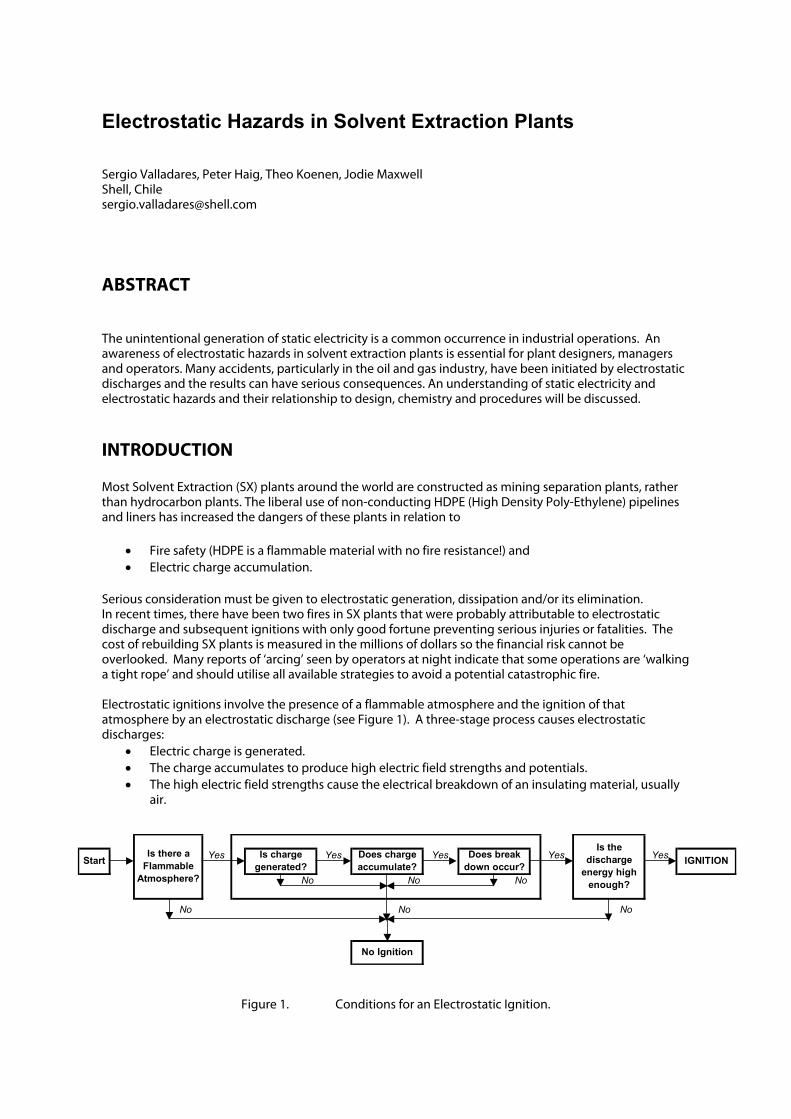
Serious consideration must be given to electrostatic generation, dissipation and/or its elimination. In recent times, there have been two fires in SX plants that were probably attributable to electrostatic discharge and subsequent ignitions with only good fortune preventing serious injuries or fatalities. The cost of rebuilding SX plants is measured in the millions of dollars so the financial risk cannot be overlooked. Many reports of ‘arcing’ seen by operators at night indicate that some operations are ‘walking a tight rope’ and should utilise all available strategies to avoid a potential catastrophic fire. Electrostatic ignitions involve the presence of a flammable atmosphere and the ignition of that atmosphere by an electrostatic discharge (see Figure 1). A three-stage process causes electrostatic discharges:
• Electric charge is generated. • The charge accumulates to produce high electric field strengths and potentials. • The high electric field strengths cause the electrical breakdown of an insulating material, usually
air.
Yes Yes Yes Yes Yes
No No No
No No No
IGNITIONStart
No Ignition
Is charge generated?
Does charge accumulate?
Does break down occur?
Is there a Flammable
Atmosphere?
Is the discharge
energy high enough?
Figure 1. Conditions for an Electrostatic Ignition.
Discharges are Incendive (capable of igniting) if they can supply the flammable atmosphere with enough energy to start combustion. The amount of energy required depends on the nature of both the flammable atmosphere and the discharge. To put this into perspective, the amount of charge that is generated when you are ‘zapped’ by your car on a dry day is up 200 times the amount of energy required to ignite a hydrocarbon gas or liquid!
In our everyday life, we refuel our petrol driven cars with a product with a flash point of <-30°C with little regard for the safety systems involved with the pumping of these products at up to 60°C above their flash point. What this shows is that safely can be achieved if design, materials of construction and common sense all come together to manage this particular risk.
2. FLAMMABLE ATMOSPHERES Flammable atmospheres are formed when flammable materials mix with air or oxygen. The flammable materials may be gases, vapours (gases in contact with their liquids), suspended droplets (mists or sprays) or suspended dusts and powders. In a Solvent Extraction circuit, the main dangers are from vapours, foams and mists. Although most SX plants utilise high flash point diluents (>75°C) that offer some intrinsic protection from ignition, a little know fact is that most hydrocarbons can ignite at up to 20°C below their flash point if the conditions are right (e.g. misting or foaming). The susceptibility of an atmosphere to electrostatic ignitions can be characterised by its flash point, flammability and ignitability.
2.1 Flash Point Flash point is the lowest temperature at which a liquid can form an ignitable mixture in air above the surface of the test liquid. Flash points are determined experimentally by heating the liquid in a closed cup at 1°C/min and then introducing a small flame just above the liquid surface each °C (Figure 2). The temperature at which there is a flash/ignition is recorded as the flash point. The lower the flash point, the easier it is to ignite the material. This laboratory test (ASTM D93 or equivalent) is somewhat artificial, although it does measure the flammability of the vapour above the liquid. This liquid is being gently stirred in a test cup, and its vapour pressure is released every minute. The less often the cup is opened, the lower the flash point achieved due to the build up of vapour pressure. In industry, most hydrocarbons are moved through high shear pumps and mixers that tend to generate mists or sprays when the hydrocarbon is exposed to air, these physical effects can lower the temperature at which a product will ignite.
2

Figure 2. ASTM D93 Pensky-Martin Flash Point Apparatus.
2.2 Flammability
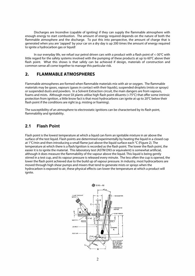
Flammable materials will only ignite if the vapours are present in concentrations that are between the upper flammable limit (UFL) and the lower flammable limit (LFL). The range between the UFL and the LFL is the flammable range and they are typically expressed as % volume in air. High flash diluents in SX plants have a typical range from a LFL of about 0.7%v/v to an UFL of about 7% v/v. Figure 3 shows the approximate correlation between the flammable range, product temperature, vapour pressure and flash point. Below the LFL, the saturated vapour is too dilute (too lean) to be flammable and above the UFL, it is too concentrated (too rich). However, care must be taken as:
• It may take a long time to establish saturation (possibly several days in a large storage tank. • In the absence of mixing, the vapour concentration will decrease with distance from the surface
of the liquid. • Mixing with air may reduce the vapour concentration. This occurs at openings such as vents or
observation hatches and may turn an over-rich mixture into a flammable mix in the flammable range.
An atmosphere must be treated as definitely flammable when the concentration of flammable material exceeds 50% of the LFL. Typically, concentrations of 10% of the LFL or less are stipulated for obtaining hot work permits. When the concentration of oxygen in an atmosphere is sufficiently low, combustion is impossible. This can be achieved by inerting the atmosphere with gases such as carbon dioxide or nitrogen.
3
Dilu
e nts
Dilu
e nts
Figure 3. Approximate Correlation between Flammable Temperature Range, Reid Vapour Pressure and Flash Point.
2.3 Ignitability The ignitability of a flammable atmosphere is directly related to the minimum ignition energy (MIE). The MIE is the minimum spark energy needed to ignite an optimum concentration of flammable material using a spark under ideal conditions. The MIE is increased at low oxygen concentrations and it is dramatically decreased at high oxygen concentrations. The MIE gives the best measure of the sensitivity of a gas or vapour to electrostatic ignitions. Most hydrocarbons have a MIE of equal to or greater than 0.2mJ. Figure 4 shows the MIE’s for various materials and type of discharge. Table 1 puts this amount of energy into perspective.
4

DiluentsDiluents
Figure 4. Approximate Minimum Ignition Energies by Discharge and Product Type.
5
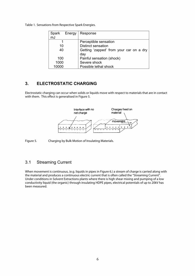
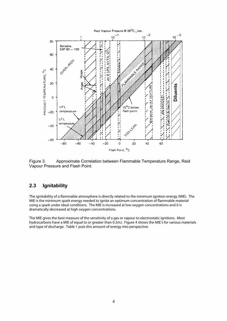
Table 1. Sensations from Respective Spark Energies.
Spark Energy mJ
Response
1 Perceptible sensation 10 Distinct sensation 40 Getting ‘zapped’ from your car on a dry
day 100 Painful sensation (shock)
1000 Severe shock 10000 Possible lethal shock
3. ELECTROSTATIC CHARGING Electrostatic charging can occur when solids or liquids move with respect to materials that are in contact with them. This effect is generalised in Figure 5.
Figure 5. Charging by Bulk Motion of Insulating Materials.
3.1 Streaming Current When movement is continuous, (e.g. liquids in pipes in Figure 6.) a stream of charge is carried along with the material and produces a continuous electric current that is often called the “Streaming Current”. Under conditions in Solvent Extractions plants where there is high shear mixing and pumping of a low conductivity liquid (the organic) through insulating HDPE pipes, electrical potentials of up to 20kV has been measured.
6
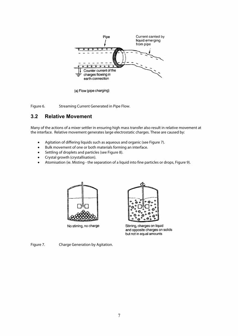
Figure 6. Streaming Current Generated in Pipe Flow.
3.2 Relative Movement Many of the actions of a mixer settler in ensuring high mass transfer also result in relative movement at the interface. Relative movement generates large electrostatic charges. These are caused by:
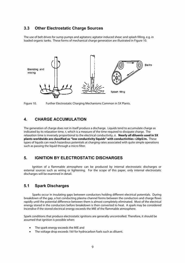
• Agitation of differing liquids such as aqueous and organic (see Figure 7). • Bulk movement of one or both materials forming an interface. • Settling of droplets and particles (see Figure 8). • Crystal growth (crystallisation). • Atomisation (ie. Misting - the separation of a liquid into fine particles or drops, Figure 9).
Figure 7. Charge Generation by Agitation.
7
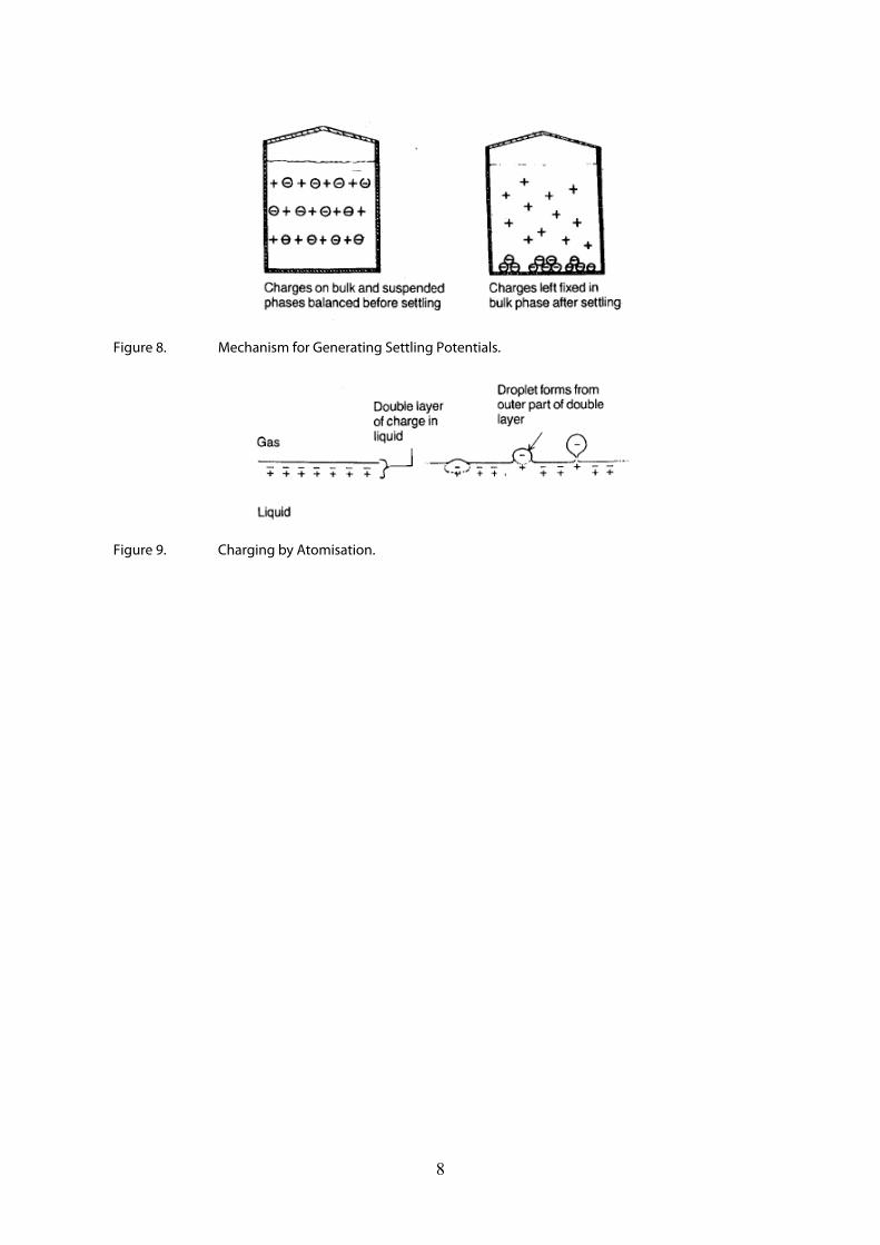
Figure 8. Mechanism for Generating Settling Potentials.
Figure 9. Charging by Atomisation.
8
3.3 Other Electrostatic Charge Sources The use of belt drives for sump pumps and agitators; agitator induced shear; and splash filling, e.g. in loaded organic tanks. These forms of mechanical charge generation are illustrated in Figure 10. Figure 10. Further Electrostatic Charging Mechanisms Common in SX Plants.
4. CHARGE ACCUMULATION The generation of charge does not in itself produce a discharge. Liquids tend to accumulate charge as indicated by its relaxation time, τ, which is a measure of the time required to dissipate charge. The relaxation time is inversely proportional to the electrical conductivity, σ. Nearly all diluents used in SX plants worldwide are classified as “low conductivity liquids” with conductivities <20pS/m. These types of liquids can reach hazardous potentials at charging rates associated with quite simple operations such as passing the liquid through a micro filter.
5. IGNITION BY ELECTROSTATIC DISCHARGES
Ignition of a flammable atmosphere can be produced by internal electrostatic discharges or external sources such as wiring or lightening. For the scope of this paper, only internal electrostatic discharges will be examined in detail.
5.1 Spark Discharges
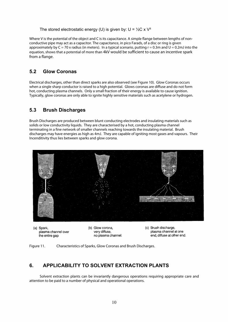
Sparks occur in insulating gaps between conductors holding different electrical potentials. During breakdown of the gap, a hot conducting plasma channel forms between the conductors and charge flows rapidly until the potential difference between them is almost completely eliminated. Most of the electrical energy stored in the conductors before breakdown is then converted to heat. A spark may be considered Incendive if the stored electrical energy exceeds the MIE of the flammable atmosphere. Spark conditions that produce electrostatic ignitions are generally uncontrolled. Therefore, it should be assumed that ignition is possible when:
• The spark energy exceeds the MIE and • The voltage drop exceeds 1kV for hydrocarbon fuels such as diluent.
9
The stored electrostatic energy (U) is given by: U = ½C x V² Where V is the potential of the object and C is its capacitance. A simple flange between lengths of non-conductive pipe may act as a capacitor. The capacitance, in pico Farads, of a disc or ring is given approximately by C = 70 x radius (in meters). In a typical scenario, putting r = 0.3m and U = 0.2mJ into the equation, shows that a potential of more than 4kV would be sufficient to cause an incentive spark from a flange.
5.2 Glow Coronas Electrical discharges, other than direct sparks are also observed (see Figure 10). Glow Coronas occurs when a single sharp conductor is raised to a high potential. Glows coronas are diffuse and do not form hot, conducting plasma channels. Only a small fraction of their energy is available to cause ignition. Typically, glow coronas are only able to ignite highly sensitive materials such as acetylene or hydrogen.
5.3 Brush Discharges Brush Discharges are produced between blunt conducting electrodes and insulating materials such as solids or low conductivity liquids. They are characterised by a hot, conducting plasma channel terminating in a fine network of smaller channels reaching towards the insulating material. Brush discharges may have energies as high as 4mJ. They are capable of igniting most gases and vapours. Their Incenditivity thus lies between sparks and glow corona.
Figure 11. Characteristics of Sparks, Glow Coronas and Brush Discharges.
6. APPLICABILITY TO SOLVENT EXTRACTION PLANTS
Solvent extraction plants can be invariantly dangerous operations requiring appropriate care and attention to be paid to a number of physical and operational operations.
10
6.1 Conductivity of the Organic The risk of an electrostatic ignition is related to the conductivity of the liquid. Low conductivity liquids (i.e. those with electrical conductivity <50pS/m) tend to generate massive charges unless they are effectively dissipated. Typical liquid handling operations in SX operations that can give rise to electrostatic ignitions are:
• Filling tanks and containers (e.g. sample buckets and graduated cylinders). • Circulating liquids through partly filled tanks. • Road tanker deliveries. • Agitation of two phase mixtures. • Settling of two phase mixtures. • Crystallisation from low conductivity liquids. • Passing liquids through insulating pipes. • Passing liquids through flexible hoses. • Filtering liquids.
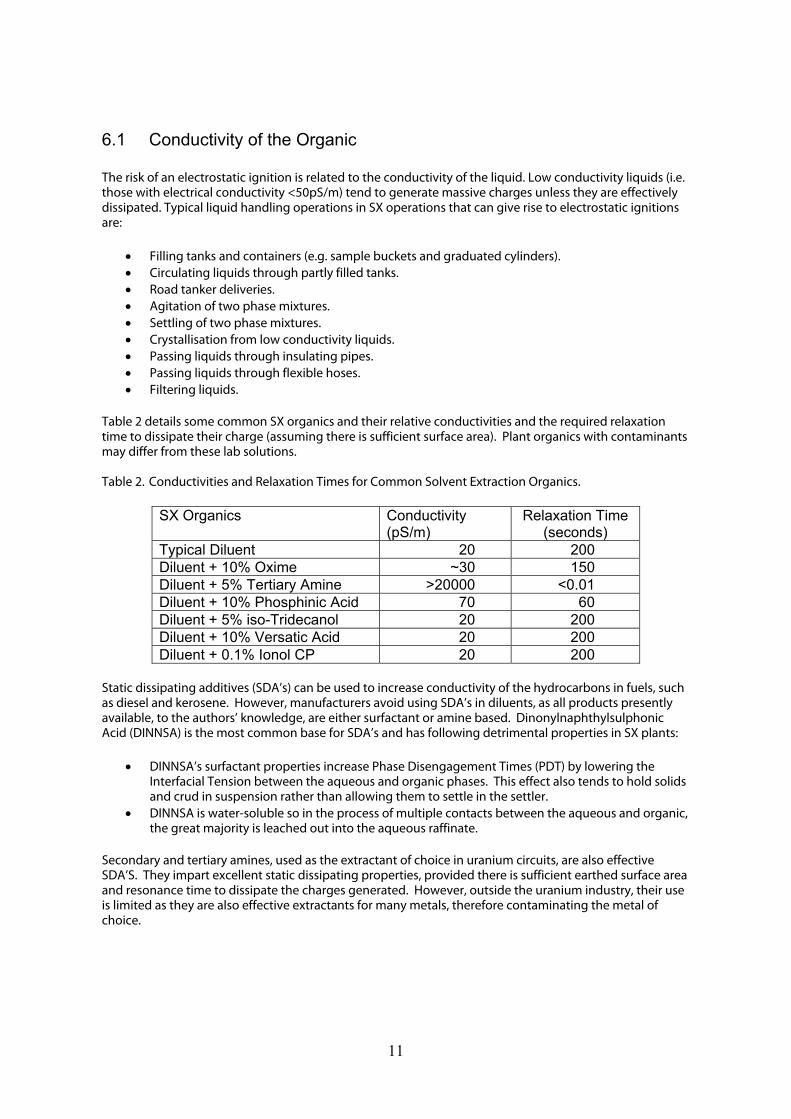
Table 2 details some common SX organics and their relative conductivities and the required relaxation time to dissipate their charge (assuming there is sufficient surface area). Plant organics with contaminants may differ from these lab solutions. Table 2. Conductivities and Relaxation Times for Common Solvent Extraction Organics.
SX Organics Conductivity (pS/m)
Relaxation Time (seconds)
Typical Diluent 20 200 Diluent + 10% Oxime ~30 150 Diluent + 5% Tertiary Amine >20000 <0.01 Diluent + 10% Phosphinic Acid 70 60 Diluent + 5% iso-Tridecanol 20 200 Diluent + 10% Versatic Acid 20 200 Diluent + 0.1% Ionol CP 20 200
Static dissipating additives (SDA’s) can be used to increase conductivity of the hydrocarbons in fuels, such as diesel and kerosene. However, manufacturers avoid using SDA’s in diluents, as all products presently available, to the authors’ knowledge, are either surfactant or amine based. Dinonylnaphthylsulphonic Acid (DINNSA) is the most common base for SDA’s and has following detrimental properties in SX plants:
• DINNSA’s surfactant properties increase Phase Disengagement Times (PDT) by lowering the Interfacial Tension between the aqueous and organic phases. This effect also tends to hold solids and crud in suspension rather than allowing them to settle in the settler.
• DINNSA is water-soluble so in the process of multiple contacts between the aqueous and organic, the great majority is leached out into the aqueous raffinate.
Secondary and tertiary amines, used as the extractant of choice in uranium circuits, are also effective SDA’S. They impart excellent static dissipating properties, provided there is sufficient earthed surface area and resonance time to dissipate the charges generated. However, outside the uranium industry, their use is limited as they are also effective extractants for many metals, therefore contaminating the metal of choice.
11
6.2 Atomisation Most solvent extraction plants experience foaming and misting from poorly designed fluid flow and/or excessive agitation. This results not only in charge generation and lowering of the flash point of the liquid, but also costly organic and target metal losses.
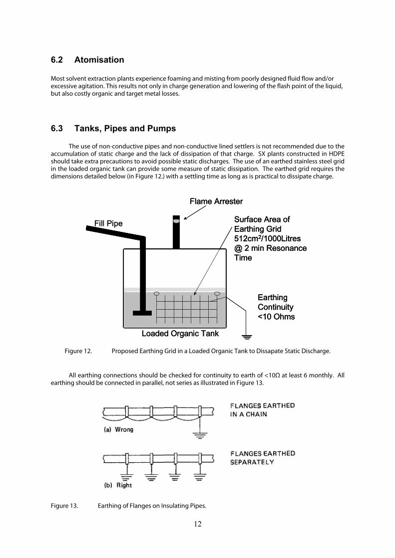
6.3 Tanks, Pipes and Pumps The use of non-conductive pipes and non-conductive lined settlers is not recommended due to the
accumulation of static charge and the lack of dissipation of that charge. SX plants constructed in HDPE should take extra precautions to avoid possible static discharges. The use of an earthed stainless steel grid in the loaded organic tank can provide some measure of static dissipation. The earthed grid requires the dimensions detailed below (in Figure 12.) with a settling time as long as is practical to dissipate charge.
Loaded Organic Tank
Surface Area of Earthing Grid512cm2/1000Litres@ 2 min ResonanceTime
Earthing Continuity<10 Ohms
Flame Arrester
Fill Pipe
Loaded Organic Tank
Surface Area of Earthing Grid512cm2/1000Litres@ 2 min ResonanceTime
Earthing Continuity<10 Ohms
Flame Arrester
Loaded Organic Tank
Surface Area of Earthing Grid512cm2/1000Litres@ 2 min ResonanceTime
Earthing Continuity<10 Ohms
Flame Arrester
Fill Pipe
Figure 12. Proposed Earthing Grid in a Loaded Organic Tank to Dissapate Static Discharge.
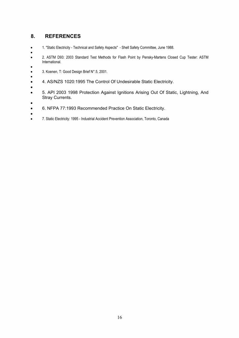
All earthing connections should be checked for continuity to earth of <10Ω at least 6 monthly. All earthing should be connected in parallel, not series as illustrated in Figure 13.
Figure 13. Earthing of Flanges on Insulating Pipes.
12

6.3.1 Tanks
• If tank walls are lined with non-conductive material, install conductive metal plates inside the tank from the bottom of the tank to the highest liquid level. Metal plates shall be bonded and ground to earth and surface area shall be not less than 512 cm2 per 1000 litres (1m³) of organic. No part of the liquid should be more than 2 m from the nearest immersed part of the earthed object.
• Fill line/discharge velocity of incoming liquid stream shall not exceed 1 metre per second. • Ensure there is sufficient settling time in the conductive tank to allow for static dissipation. A
minimum of 2 minutes is recommended. • Fill pipe shall have a large diameter outlet and be directed to minimise turbulence within the
tank. It should discharge near the bottom of the tank and submerged to a depth not less than 500 mm or twice the inside diameter of the pipe, whichever is the larger. Care should be taken to avoid disturbing a water bottom.
• Remove and/or ground conductive spark promoters. • All conductive tank components (e.g. hatch cover, liquid level instrument, etc.) shall be grounded. • If no metal plates are installed inside the tank/pond, conductive surface skimmers shall not be
used. • Line tank walls with conductive material (e.g. stainless steel or conductive GRP) and also ground.
6.3.2 Mixer/Settlers
• All of the above under tanks. • Bond and ground all conductive parts (all metal and/or moving parts of the equipment). • Avoid excessive agitating of aqueous with organic. • If mixer settler walls are lined with non-conductive material, install conductive metal plates inside
the mixer settler just below the liquid surface. Metal plates shall be bonded and ground to earth and surface area shall be not less than 512 cm2 per 1000 litres (1m³) of organic. No part of the liquid should be more than 2m from the nearest immersed part of the earthed object. Earthed stainless steel picket fences can be an effective means of dissipating some of the charge.
6.3.3 Piping Systems
• Piping systems should be made of conducting material e.g. stainless steel or conductive GRP. • Pipes should always be kept full of organic. If there are vapour spaces, it is likely to form a
potentially flammable atmosphere. • Where possible avoid flow through filters and screens. • Liquid flow velocity V2d (V is flow velocity in metres per second and d is pipe diameter in metres)
shall not exceed 0.64. • Install relaxation section(s) in non-conductive piping system by inserting a suitable length of
earthed (enlarged diameter) metal pipe. The length of the pipe can be calculated by: l/V=(3x18)σ, where,
L = length of relaxation section in metres V = flow velocity in section, in meters per second σ = liquid conductivity, in pico Siemens per metre (typically 30pS/m) This relaxation section should be constructed and connected so as to reduce turbulence to a minimum. It should be close to the tank into which the liquid is discharging, and be downstream from any filters and coalesces.
• All electrically isolated sections of metallic piping, valves etc. shall be bonded and grounded to earth.
13

6.3.4 Pumps
• Because the temperature of the solvent in the seal chamber is very close to the flash point of the solvent it is recommended that double mechanical seals with barrier liquid (and seal supporting system) be installed on all solvent pumps. The pumps could be connected to one seal supporting system.
• Avoid belt driven equipment were hydrocarbons are present. For pumps operating above an open sump containing solvents install direct drives only. Heavier than air vapours can accumulate in the sump and be ignited by an electrostatic discharge from the friction on the belt.
6.4 Hazardous Areas All solvent extraction plants should be audited to ascertain the hazard areas and the contour diagrams in 3 dimensions. The classifications are as follows:
ZONE 0 A flammable atmosphere is continuously present or present for long periods of time. ZONE 1 A flammable atmosphere is likely to occur in normal operation.
ZONE 2 A flammable atmosphere is not likely to occur in normal operation and when one does occur, it will exist only for a short while.
Ensure that only electrical equipment that is rated for the respective Zones be utilised.
6.5 People and Clothing Ignitions are produced by sparks from people when:-
• A flammable atmosphere is present • There is a mechanism for generating charge on people • People have a high resistance to earth so that charge accumulates (i.e. they are electrically
insulated)
If a person is charged and sufficiently insulated, it is virtually inevitable that they will at some stage approach an earthed object and produce a spark. The potential on a person may exceed 30kV and the stored charge can be as high as 90mJ. The sparks generated from a person can therefore be incendive. Mechanisms for charging the human body include:
• Walking on insulated floor coverings and carpet (Figure 14). • Cleaning an object by rubbing (Figure 15). • Contacting another charged object. • Induction in the vicinity of another charged object. • Sliding off a seat. • Removing clothing (especially when contaminated with organic).
14

Figure 14. Charge Accumulation on a Person Figure 15. Charge Accumulation on an Insulated Floor or Wearing on insulating solids (e.g. Rubbing Insulated Footwear. An Insulated Pipe).
When there is an ignition risk, footwear, gloves and flooring should be either conductive or anti-static. Conducting surfaces such as metal grid flooring should be kept clean and free from insulating deposits.
Clothing should have a surface resistance of less than 5 x 10¹⁰Ω. Natural fibres such as cotton, flax and linen will meet this requirement if the relative humidity is above 65%. Synthetic materials will often fail to meet the requirement unless they are specially treated. In most cases, this treatment needs to be regularly reapplied. Alternatively, conductive fibres may be incorporated into the fabrics. These act by dissipating charge via small non-incendive coronas and are effective even under dry conditions.
7. CONCLUSIONS
Static electricity is, in many respects, the "unappreciated" and least understood electrical hazard in solvent extraction plants. It does not require cables and there are no terminals or switches - in fact, often there is no indication of its presence -. However, the consequences of not taking adequate precautions when there is a possibility of an accumulated electrostatic charge being present can be disastrous.
To most solvent extraction plants we would recommend the following action list. However, always consult with the relevant national and international regulatory requirements.
1. Ascertain the conductivity and electrical potential of your organic. 2. Review the materials of construction of the plant. 3. Have the plant audited to assess the hazardous zone areas of the plant. 4. Perform a ‘risk assessment audit’ to identify hazards such as hazardous ratings of electrical
equipment. 5. Issue staff with appropriate clothing and footwear. 6. Be ever vigilant to the possibility of static build up and discharges.
As mentioned previously, any industry dealing with hydrocarbons carries an element of risk,
however, if one ‘manages the risk’, safe continued operation can be achieved with little or no risk to employees or the company.
15
16
8. REFERENCES • 1. "Static Electricity - Technical and Safety Aspects" - Shell Safety Committee, June 1988. • • 2. ASTM D93: 2003 Standard Test Methods for Flash Point by Pensky-Martens Closed Cup Tester: ASTM
International. • • 3. Koenen, T: Good Design Brief N°.5, 2001. • • 4. AS/NZS 1020:1995 The Control Of Undesirable Static Electricity. • • 5. API 2003 1998 Protection Against Ignitions Arising Out Of Static, Lightning, And
Stray Currents. • • 6. NFPA 77:1993 Recommended Practice On Static Electricity. • • 7. Static Electricity: 1995 - Industrial Accident Prevention Association, Toronto, Canada