electrical wire routing preface -...
TRANSCRIPT
Electrical Wire Routing
Preface
What's New?
Getting Started
Basic Tasks
Advanced Tasks
Workbench Description
Customizing
Glossary
Index
© Dassault Systèmes 1994-2000. All rights reserved.
TOC
file:///E|/Www/ADGdocR5/EwrEnglish/ewrug.doc/src/ewrugtoc.htm [09/25/2000 10:34:36]
PrefaceThe CATIA Version 5 Electrical Wire Routing is a new generation product which manages thedefinition of electrical wires within the digital mock-up according to the functional definition ofelectrical signal. It enables the users to solve complex routing problems within the context ofthe physical mock-up.
The CATIA - Electrical Wire Routing offers the following main functions:Routing an electrical signal defined in the functional systemDefine electrical wires on bundle segmentsDefine electrical signal routes on pathwaysAssign, manage and optimize electrical wire connection locationSplit and merge electrical wire connectionsAccess electrical wire definition from catalogsAssign wire to terminationExport wire route in a flat fileIntegration with VPM1 on Unix platform.
As a scalable product, CATIA Version 5 Electrical Wire Routing can be used in cooperationwith other current or future companion products of the next CATIA generation such as CATIAVersion 5 Electrical Librarian and CATIA Version 5 Electrical System Functional Design.
Using This GuideMore Information
Preface
file:///E|/Www/ADGdocR5/EwrEnglish/ewrug.doc/src/ewrugpr01.htm [09/25/2000 10:34:44]
Using This GuideThis guide is intended for the user who needs to become quickly familiar with the CATIA -Electrical Wire Routing Version 5 product. The user should be familiar with basic CATIAVersion 5 concepts such as document windows, standard and view toolbars.
To get the most out of this guide, we suggest you start reading and performing the step-by-steptutorial "Getting Started".
The next sections deal with the more detailed capabilities of the product.
Using This Guide
file:///E|/Www/ADGdocR5/EwrEnglish/ewrug.doc/src/ewrugpr02.htm [09/25/2000 10:34:48]
Where to Find More InformationPrior to reading this book, we recommend that you read the CATIA - Infrastructure User'sGuide.The CATIA - Assembly Design and CATIA - V4 Integration Version 5 User's Guides may proveuseful, as well as the CATIA - Systems Space Reservation and CATIA - Electrical SystemFunctional Definition.Certain conventions are used in CATIA documentation to help you recognize and understandimportant concepts and specifications
More Information
file:///E|/Www/ADGdocR5/EwrEnglish/ewrug.doc/src/ewrugpr03.htm [09/25/2000 10:34:51]
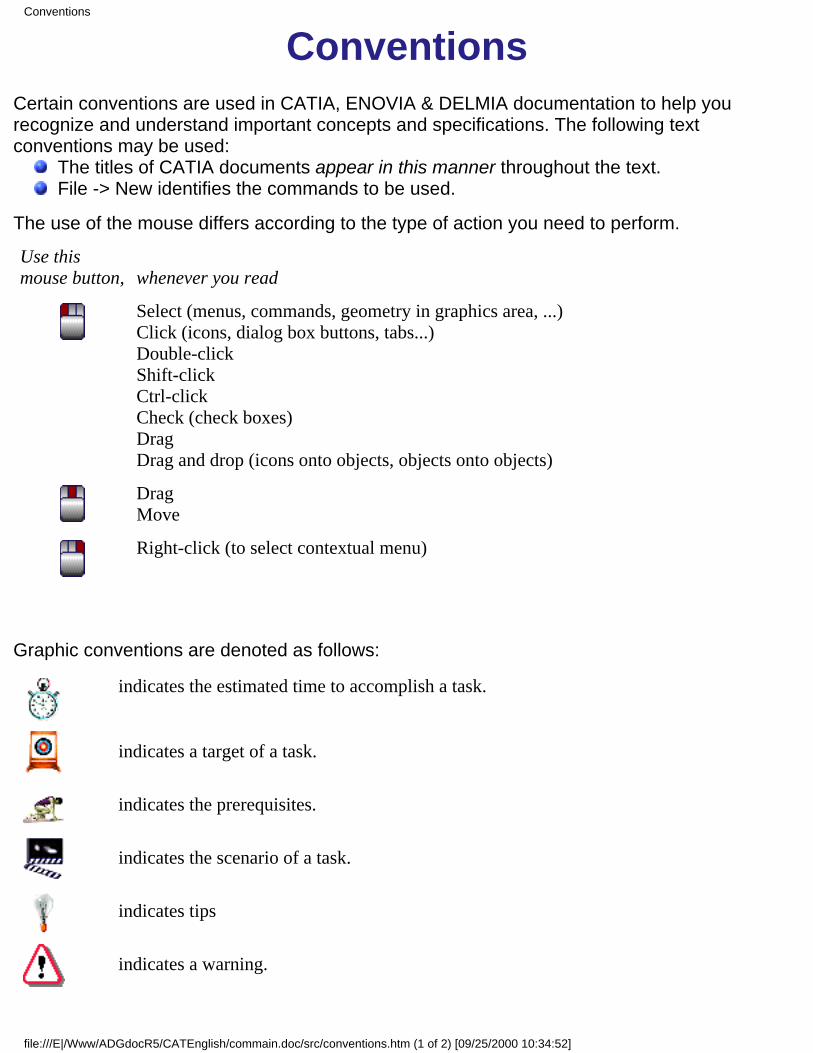
ConventionsCertain conventions are used in CATIA, ENOVIA & DELMIA documentation to help yourecognize and understand important concepts and specifications. The following textconventions may be used: The titles of CATIA documents appear in this manner throughout the text. File -> New identifies the commands to be used.
The use of the mouse differs according to the type of action you need to perform.
Use thismouse button, whenever you read
Select (menus, commands, geometry in graphics area, ...)Click (icons, dialog box buttons, tabs...)Double-clickShift-clickCtrl-clickCheck (check boxes)DragDrag and drop (icons onto objects, objects onto objects)
DragMove
Right-click (to select contextual menu)
Graphic conventions are denoted as follows:
indicates the estimated time to accomplish a task.
indicates a target of a task.
indicates the prerequisites.
indicates the scenario of a task.
indicates tips
indicates a warning.
Conventions
file:///E|/Www/ADGdocR5/CATEnglish/commain.doc/src/conventions.htm (1 of 2) [09/25/2000 10:34:52]
indicates information.
indicates the end of a task.
indicates functionalities that are new or enhanced with this Release.Enhancements can also be identified by a blue-colored background in the left-handmargin.
Conventions
file:///E|/Www/ADGdocR5/CATEnglish/commain.doc/src/conventions.htm (2 of 2) [09/25/2000 10:34:52]
What's New?This table identifies what new or improved capabilities have been documented in Version 5Release 5 of the CATIA Electrical Wire Routing.
New:CATIA - Knowledgeware is now used to manage pathway-signal compatibility.Inter-signal compatibility makes the route optimization easier.Separation code settings:
a signal-arc rule option is now available for the file based separation code,a rule based separation code is now available, with signal-signal and signal-arcoptions.
Extremity color: the color of the extremity boxes can now be customized.Enhanced:
The signal priorities defined in the Electrical System Functional Definition applicationare now taken into account.
What's New
file:///E|/Www/ADGdocR5/EwrEnglish/ewrug.doc/src/ewrugwn.htm [09/25/2000 10:34:57]
Getting StartedBefore getting into the detailed instructions for using CATIA - Electrical Wire RoutingVersion 5, the following tutorial provides a step-by-step scenario demonstrating how touse key functionalities.
Before starting this scenario, you should be familiar with the basic commands commonto all workbenches. These are described in the CATIA - Infrastructure User's Guide.
The main tasks proposed in this section are:
Accessing the WorkbenchCreating the BundleDefining the Context
Routing a Signal AutomaticallyMoving a Wire Connection
All together, these tasks should take about 10 minutes to complete.
Getting Started
file:///E|/Www/ADGdocR5/EwrEnglish/ewrug.doc/src/ewruggs01.htm [09/25/2000 10:35:08]
Accessing the Electrical Wire RoutingWorkbench
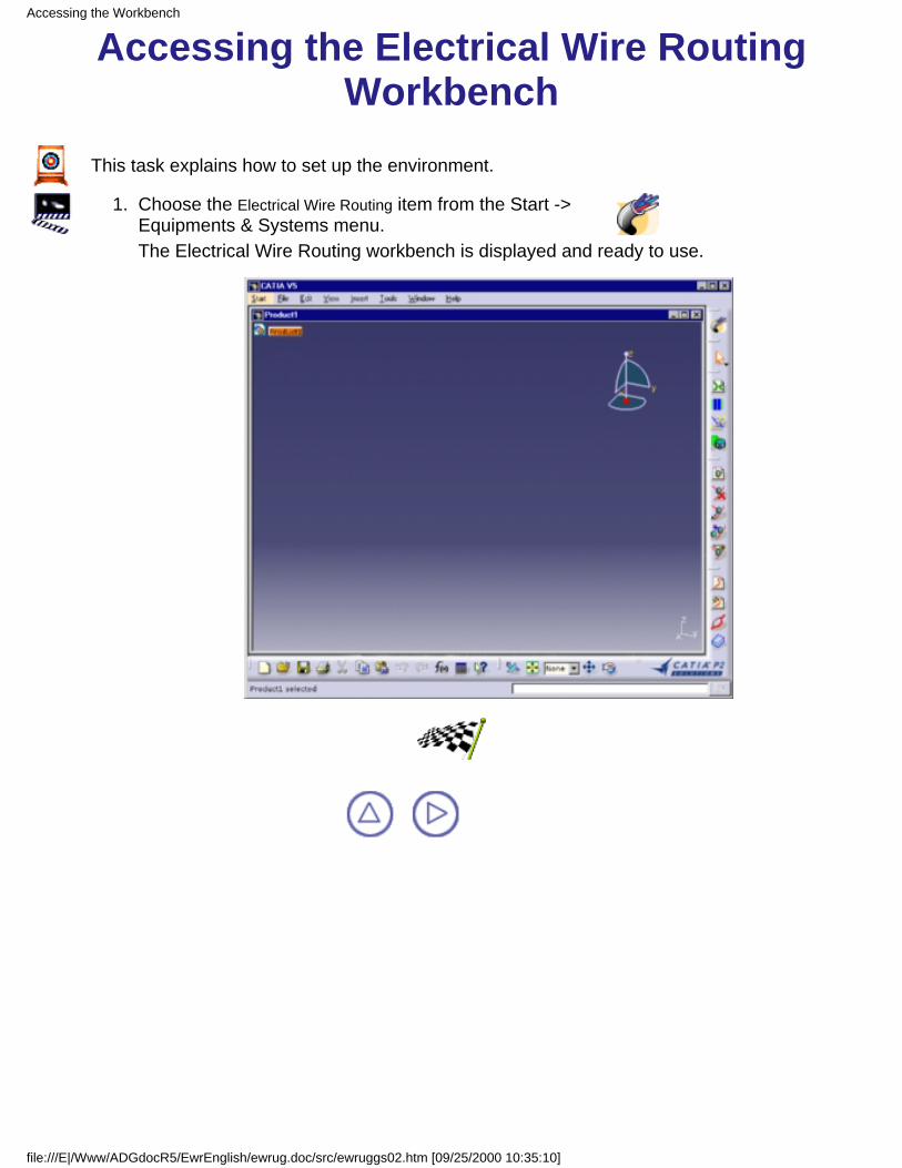
This task explains how to set up the environment.
Choose the Electrical Wire Routing item from the Start -> Equipments & Systems menu.
1.
The Electrical Wire Routing workbench is displayed and ready to use.
Accessing the Workbench
file:///E|/Www/ADGdocR5/EwrEnglish/ewrug.doc/src/ewruggs02.htm [09/25/2000 10:35:10]
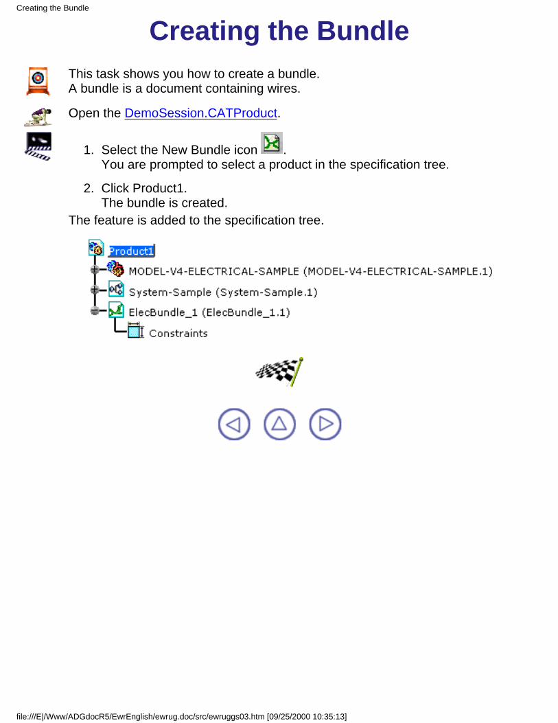
Creating the BundleThis task shows you how to create a bundle.A bundle is a document containing wires.
Open the DemoSession.CATProduct.
Select the New Bundle icon .You are prompted to select a product in the specification tree.
1.
Click Product1.The bundle is created.
2.
The feature is added to the specification tree.
Creating the Bundle
file:///E|/Www/ADGdocR5/EwrEnglish/ewrug.doc/src/ewruggs03.htm [09/25/2000 10:35:13]

Defining the Routing ContextThis task shows you how to choose the context, it is to say the signal to route andthe entity it belongs to.
The DemoSession.CATProduct is still open from the previous task.
Double-click to activate the newly created bundle.1.
Select the signal in the combo box: Signal-A.1
The routing context is defined.
2.
The extremities of the signal are visualized as shown below:A box is displayed to help you recognize the extremities of the signal.
Defining the Context
file:///E|/Www/ADGdocR5/EwrEnglish/ewrug.doc/src/ewruggs04.htm (1 of 2) [09/25/2000 10:35:16]

Defining the Context
file:///E|/Www/ADGdocR5/EwrEnglish/ewrug.doc/src/ewruggs04.htm (2 of 2) [09/25/2000 10:35:16]
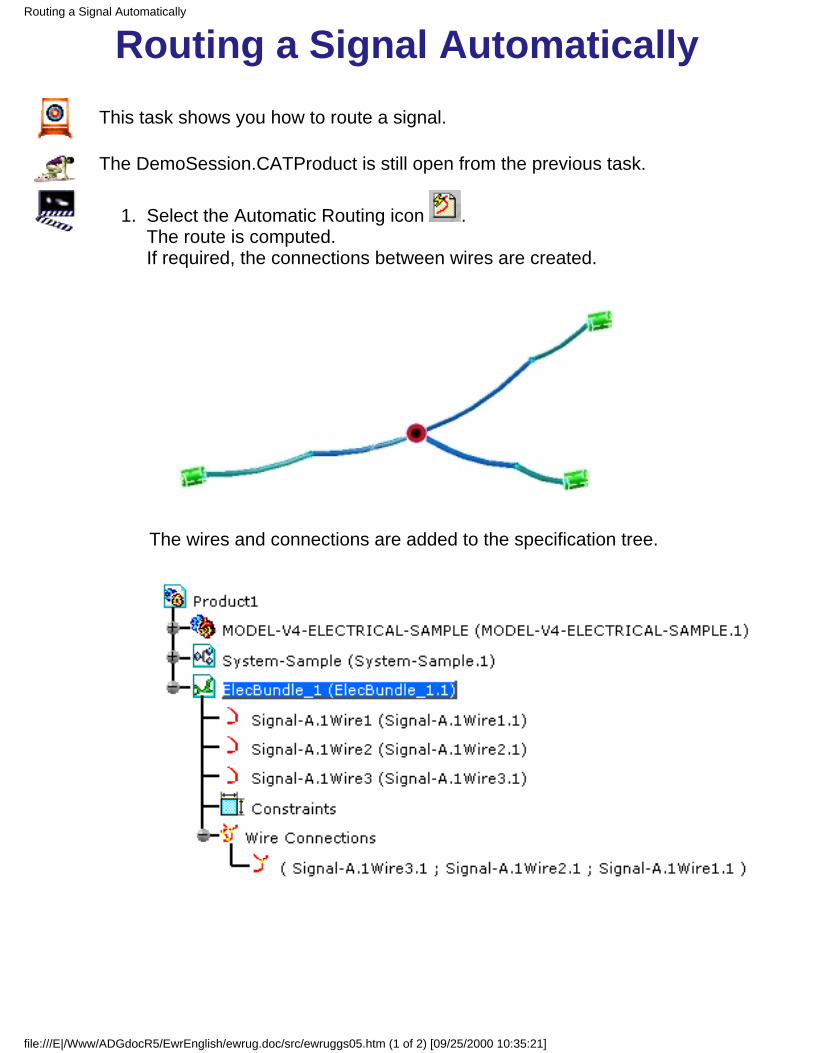
Routing a Signal AutomaticallyThis task shows you how to route a signal.
The DemoSession.CATProduct is still open from the previous task.
Select the Automatic Routing icon .The route is computed.If required, the connections between wires are created.
The wires and connections are added to the specification tree.
1.
Routing a Signal Automatically
file:///E|/Www/ADGdocR5/EwrEnglish/ewrug.doc/src/ewruggs05.htm (1 of 2) [09/25/2000 10:35:21]
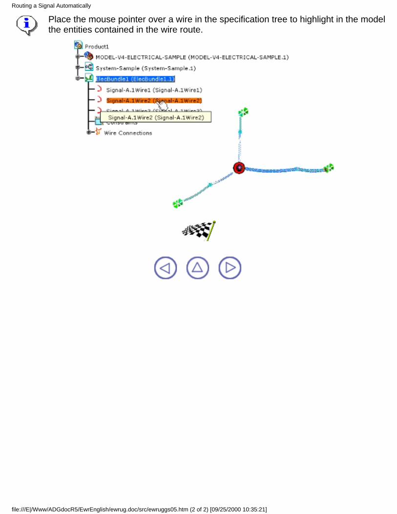
Place the mouse pointer over a wire in the specification tree to highlight in the modelthe entities contained in the wire route.
Routing a Signal Automatically
file:///E|/Www/ADGdocR5/EwrEnglish/ewrug.doc/src/ewruggs05.htm (2 of 2) [09/25/2000 10:35:21]
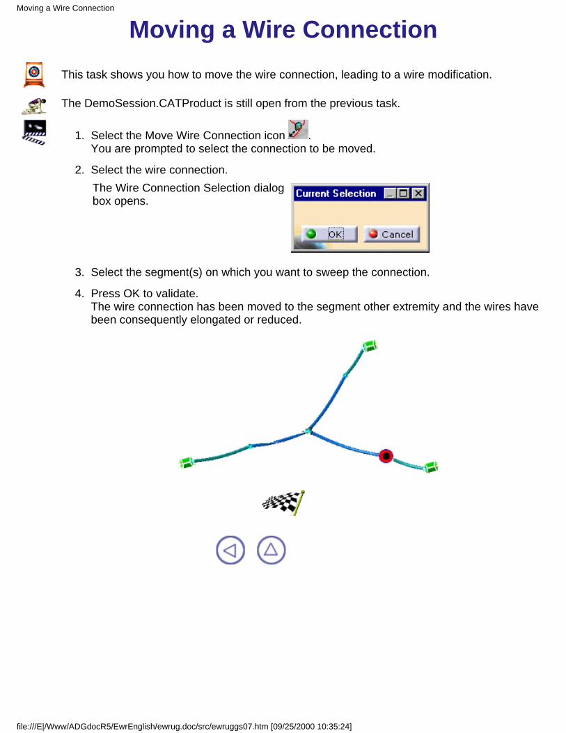
Moving a Wire ConnectionThis task shows you how to move the wire connection, leading to a wire modification.
The DemoSession.CATProduct is still open from the previous task.
Select the Move Wire Connection icon .You are prompted to select the connection to be moved.
1.
Select the wire connection.The Wire Connection Selection dialogbox opens.
2.
Select the segment(s) on which you want to sweep the connection.3.
Press OK to validate.The wire connection has been moved to the segment other extremity and the wires havebeen consequently elongated or reduced.
4.
Moving a Wire Connection
file:///E|/Www/ADGdocR5/EwrEnglish/ewrug.doc/src/ewruggs07.htm [09/25/2000 10:35:24]
Basic TasksThe Basic Tasks section explains and illustrates how to create various kinds of features.The table below lists the information you will find.
Starting...Creating the Session...
Defining the Routing ContextWorking with Wires
Working with Signal RoutesWorking with Wire Connections
Using Catalogs (if ELB)V4 Interoperability
VPM1 Interoperability
Basic Tasks
file:///E|/Www/ADGdocR5/EwrEnglish/ewrug.doc/src/ewrugbt0000.htm [09/25/2000 10:35:31]
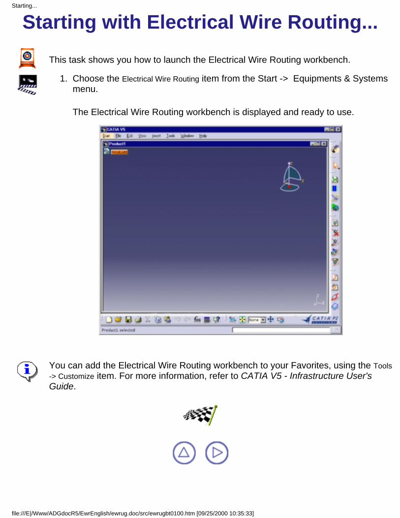
Starting with Electrical Wire Routing...This task shows you how to launch the Electrical Wire Routing workbench.
Choose the Electrical Wire Routing item from the Start -> Equipments & Systemsmenu.
1.
The Electrical Wire Routing workbench is displayed and ready to use.
You can add the Electrical Wire Routing workbench to your Favorites, using the Tools-> Customize item. For more information, refer to CATIA V5 - Infrastructure User'sGuide.
Starting...
file:///E|/Www/ADGdocR5/EwrEnglish/ewrug.doc/src/ewrugbt0100.htm [09/25/2000 10:35:33]
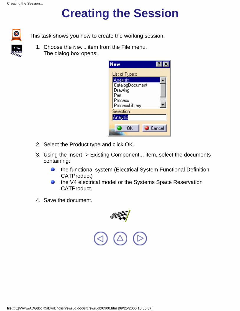
Creating the SessionThis task shows you how to create the working session.
Choose the New... item from the File menu.The dialog box opens:
1.
Select the Product type and click OK.2.
Using the Insert -> Existing Component... item, select the documentscontaining:
the functional system (Electrical System Functional DefinitionCATProduct)the V4 electrical model or the Systems Space ReservationCATProduct.
3.
Save the document.4.
Creating the Session...
file:///E|/Www/ADGdocR5/EwrEnglish/ewrug.doc/src/ewrugbt0900.htm [09/25/2000 10:35:37]
Defining the Routing ContextCreate the bundle to receive the wire and the connection.
Select the signal to be routed through wires and connections.
Defining the Routing Context
file:///E|/Www/ADGdocR5/EwrEnglish/ewrug.doc/src/ewrugbt0200.htm [09/25/2000 10:35:38]

Creating a BundleThis task shows you how to create a bundle.A bundle is a document containing wires.
Open the StartupSession.CATProduct document from the samples directory.
Select the New Bundle icon .You are prompted to choose the product it belongs to in the specification tree.
1.
Choose Startup.The bundle is created.The feature is added to the specification tree.
2.
Double-click the bundle to activate it before creating the wires.3.
A bundle is associated to a geometrical bundle by the wires it contains.
Creating a Bundle
file:///E|/Www/ADGdocR5/EwrEnglish/ewrug.doc/src/ewrugbt0201.htm [09/25/2000 10:35:41]

Selecting the SignalOnce the bundle is created, you need to select the signal to complete the routingcontext definition.
The StartupSession.CATProduct document is still open from the previous task.
There are two ways to select the signal:using the combo listusing the Signal multi-selection dialog box.
Using the combo list
Click the Signal field.1.
Drag the mouse to Signal-3.1.2.
When you release the mouse button, the signal is selected (Signal-3.1).
Using the Signal multi-selection dialog box
Click the Select Signal icon .The Signal Selection dialog box opens.
1.
Select one or several signals using Ctrl key.2.
Selecting the Signal
file:///E|/Www/ADGdocR5/EwrEnglish/ewrug.doc/src/ewrugbt0202.htm (1 of 2) [09/25/2000 10:35:43]
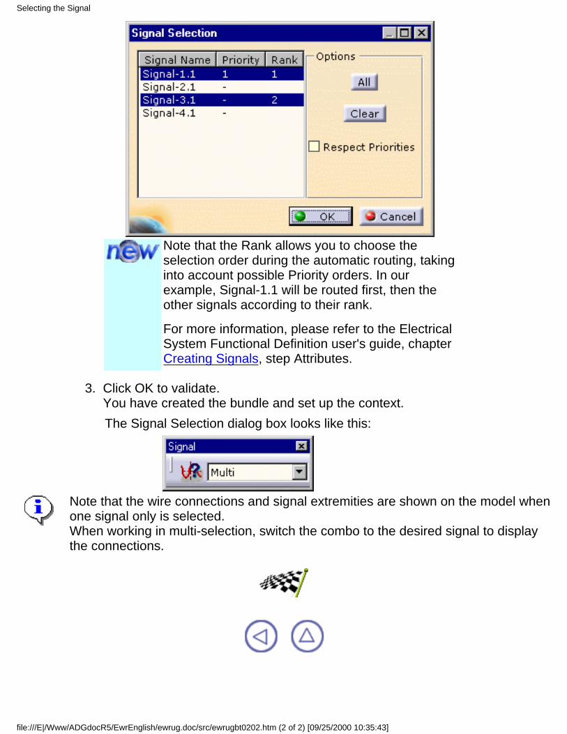
Note that the Rank allows you to choose theselection order during the automatic routing, takinginto account possible Priority orders. In ourexample, Signal-1.1 will be routed first, then theother signals according to their rank.
For more information, please refer to the ElectricalSystem Functional Definition user's guide, chapterCreating Signals, step Attributes.
Click OK to validate.You have created the bundle and set up the context.The Signal Selection dialog box looks like this:
3.
Note that the wire connections and signal extremities are shown on the model whenone signal only is selected.When working in multi-selection, switch the combo to the desired signal to displaythe connections.
Selecting the Signal
file:///E|/Www/ADGdocR5/EwrEnglish/ewrug.doc/src/ewrugbt0202.htm (2 of 2) [09/25/2000 10:35:43]

Working with Wires
Create a Wire in an existing V4 bundle segment
Automatic Routing: finds the shortest route, taking advantage of knowledgeware
Modifying the Route: changes the signal route through the networkDeleting a wire also deletes the unused connection.
Working with Wires
file:///E|/Www/ADGdocR5/EwrEnglish/ewrug.doc/src/ewrugbt0300.htm [09/25/2000 10:35:53]
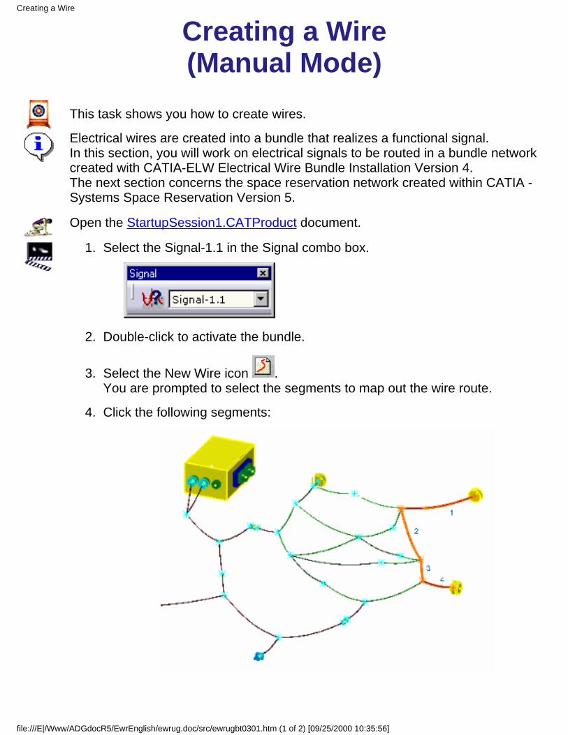
Creating a Wire(Manual Mode)
This task shows you how to create wires.
Electrical wires are created into a bundle that realizes a functional signal.In this section, you will work on electrical signals to be routed in a bundle networkcreated with CATIA-ELW Electrical Wire Bundle Installation Version 4.The next section concerns the space reservation network created within CATIA -Systems Space Reservation Version 5.
Open the StartupSession1.CATProduct document.
Select the Signal-1.1 in the Signal combo box.1.
Double-click to activate the bundle.2.
Select the New Wire icon .You are prompted to select the segments to map out the wire route.
3.
Click the following segments:4.
Creating a Wire
file:///E|/Www/ADGdocR5/EwrEnglish/ewrug.doc/src/ewrugbt0301.htm (1 of 2) [09/25/2000 10:35:56]
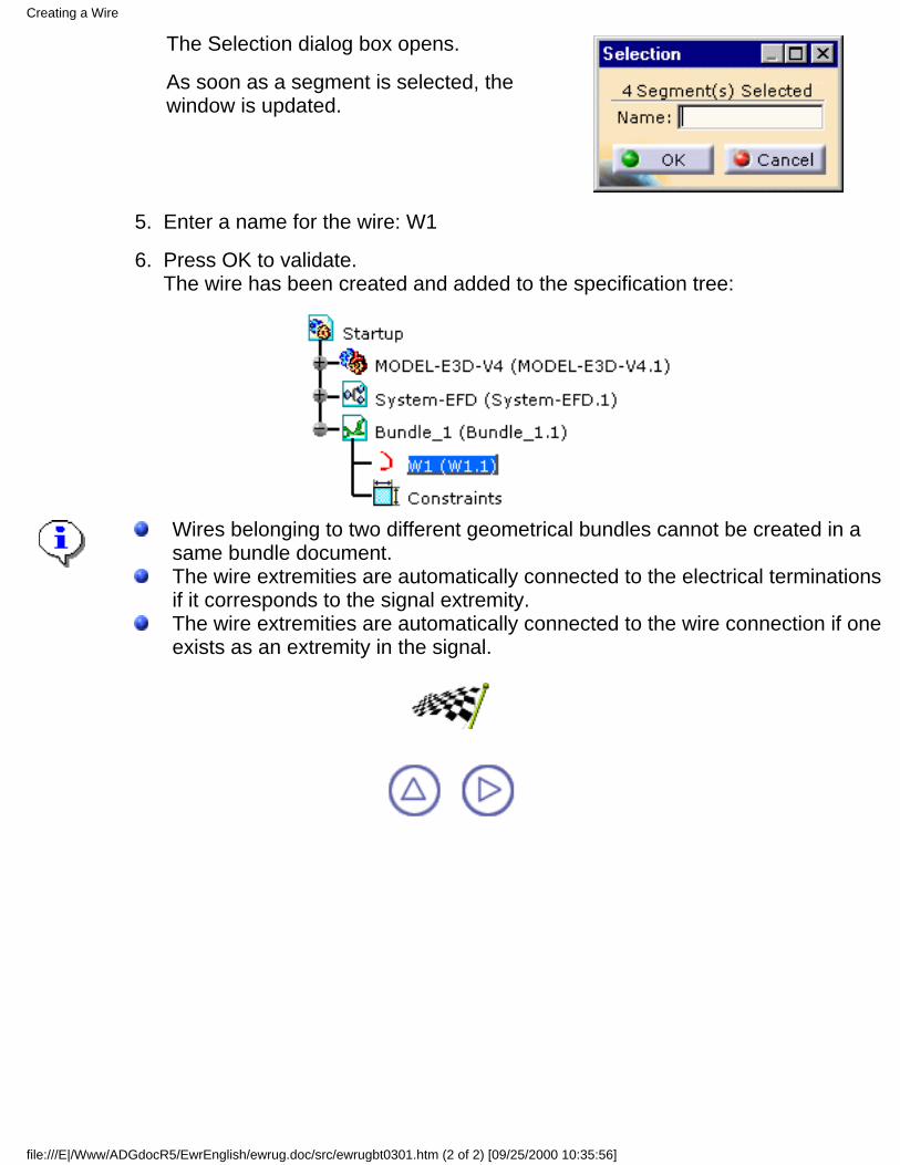
The Selection dialog box opens.
As soon as a segment is selected, thewindow is updated.
Enter a name for the wire: W1 5.
Press OK to validate.The wire has been created and added to the specification tree:
6.
Wires belonging to two different geometrical bundles cannot be created in asame bundle document.The wire extremities are automatically connected to the electrical terminationsif it corresponds to the signal extremity.The wire extremities are automatically connected to the wire connection if oneexists as an extremity in the signal.
Creating a Wire
file:///E|/Www/ADGdocR5/EwrEnglish/ewrug.doc/src/ewrugbt0301.htm (2 of 2) [09/25/2000 10:35:56]

Routing a Wire(Automatic Mode)
This task shows you how to route a wire automatically.
The algorithm optimizes the wire route according to company criteria, with thefollowing capabilities:
find the shortest wire routeroute multiple extremities signalsroute several signals at a time in compliance with a priority and a rank ordermanage available areas in the pathwaymanage separation code for compatibility between signal and pathway with acompatibility table and CATIA knowledgewareposition automatically the connections at the wire forks.
Open the StartupSession1.CATProduct document.
Set up the routing context with two signals:
Note that the Rank allows you to choose the selectionorder during the automatic routing, taking intoaccount possible Priority orders. In our example,Signal-1.1 will be routed first, then the other signalsaccording to their rank.
For more information, please refer to the ElectricalSystem Functional Definition user's guide, chapterCreating Signals, step Attributes.
1.
Routing a Wire
file:///E|/Www/ADGdocR5/EwrEnglish/ewrug.doc/src/ewrugbt0302.htm (1 of 2) [09/25/2000 10:35:59]
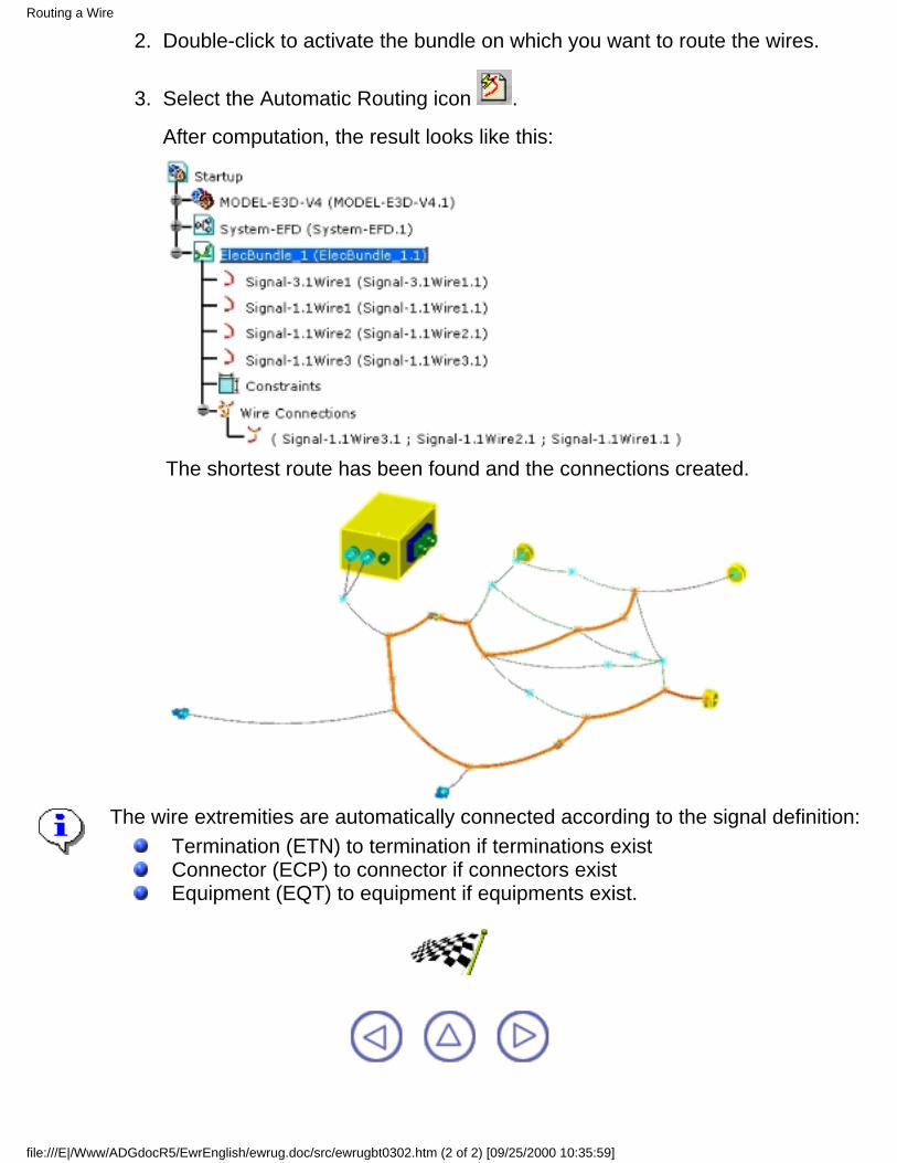
Double-click to activate the bundle on which you want to route the wires.2.
Select the Automatic Routing icon .3.
After computation, the result looks like this:
The shortest route has been found and the connections created.
The wire extremities are automatically connected according to the signal definition:Termination (ETN) to termination if terminations existConnector (ECP) to connector if connectors existEquipment (EQT) to equipment if equipments exist.
Routing a Wire
file:///E|/Www/ADGdocR5/EwrEnglish/ewrug.doc/src/ewrugbt0302.htm (2 of 2) [09/25/2000 10:35:59]
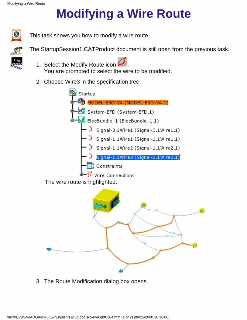
Modifying a Wire RouteThis task shows you how to modify a wire route.
The StartupSession1.CATProduct document is still open from the previous task.
Select the Modify Route icon .You are prompted to select the wire to be modified.
1.
Choose Wire3 in the specification tree.
The wire route is highlighted.
2.
The Route Modification dialog box opens.3.
Modifying a Wire Route
file:///E|/Www/ADGdocR5/EwrEnglish/ewrug.doc/src/ewrugbt0304.htm (1 of 2) [09/25/2000 10:36:06]
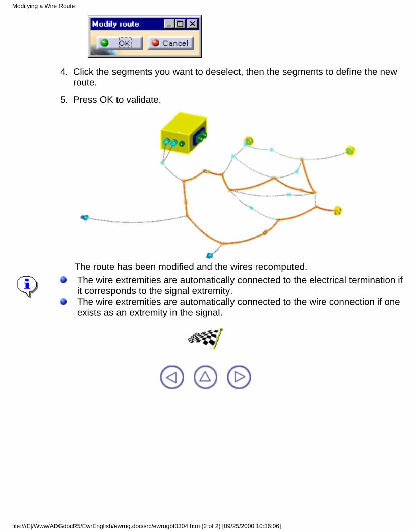
Click the segments you want to deselect, then the segments to define the newroute.
4.
Press OK to validate.
The route has been modified and the wires recomputed.
5.
The wire extremities are automatically connected to the electrical termination ifit corresponds to the signal extremity.The wire extremities are automatically connected to the wire connection if oneexists as an extremity in the signal.
Modifying a Wire Route
file:///E|/Www/ADGdocR5/EwrEnglish/ewrug.doc/src/ewrugbt0304.htm (2 of 2) [09/25/2000 10:36:06]
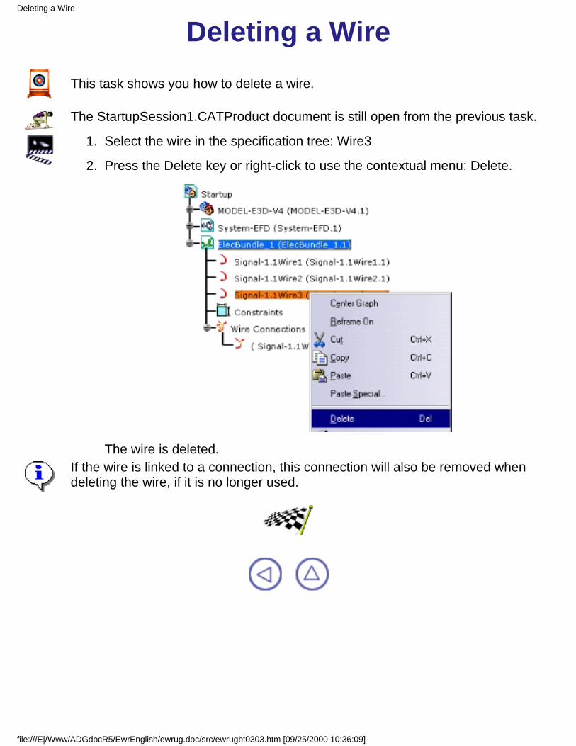
Deleting a WireThis task shows you how to delete a wire.
The StartupSession1.CATProduct document is still open from the previous task.
Select the wire in the specification tree: Wire31.
Press the Delete key or right-click to use the contextual menu: Delete.2.
The wire is deleted.If the wire is linked to a connection, this connection will also be removed whendeleting the wire, if it is no longer used.
Deleting a Wire
file:///E|/Www/ADGdocR5/EwrEnglish/ewrug.doc/src/ewrugbt0303.htm [09/25/2000 10:36:09]
Working with Signal Routes
Reconciling: Associate the functional and the physical objects.
Creating: Route automatically on the signal selected.
Deleting: Remove the signal selected.
Working with Signal Routes
file:///E|/Www/ADGdocR5/EwrEnglish/ewrug.doc/src/ewrugbt0400.htm [09/25/2000 10:36:14]

Reconciling ObjectsThis task prepares the signal route creation on pathways.
In this section, you will work on electrical signals to be routed in a space reservationnetwork (pathways) created within CATIA Systems Space Reservation Version 5.You will first reconcile the functional with the physical objects then create the signalroute.Two cases are available:
reconciling a functional connector with a physical connector:all the functional connectors belonging to a functional equipment must bereconciled with physical connectors belonging to the same reservation box(ArrBox).reconciling a functional equipment with a physical equipment:a physical connector must be specifically created, representing the signalconnection point onto the physical equipment. In this case, the physicalequipment has an extra connector which does not exist in the functionaldefinition.
Open the SSRSession.CATProduct document.
Reconciling Objects
file:///E|/Www/ADGdocR5/EwrEnglish/ewrug.doc/src/ewrugbt0404.htm (1 of 3) [09/25/2000 10:36:16]
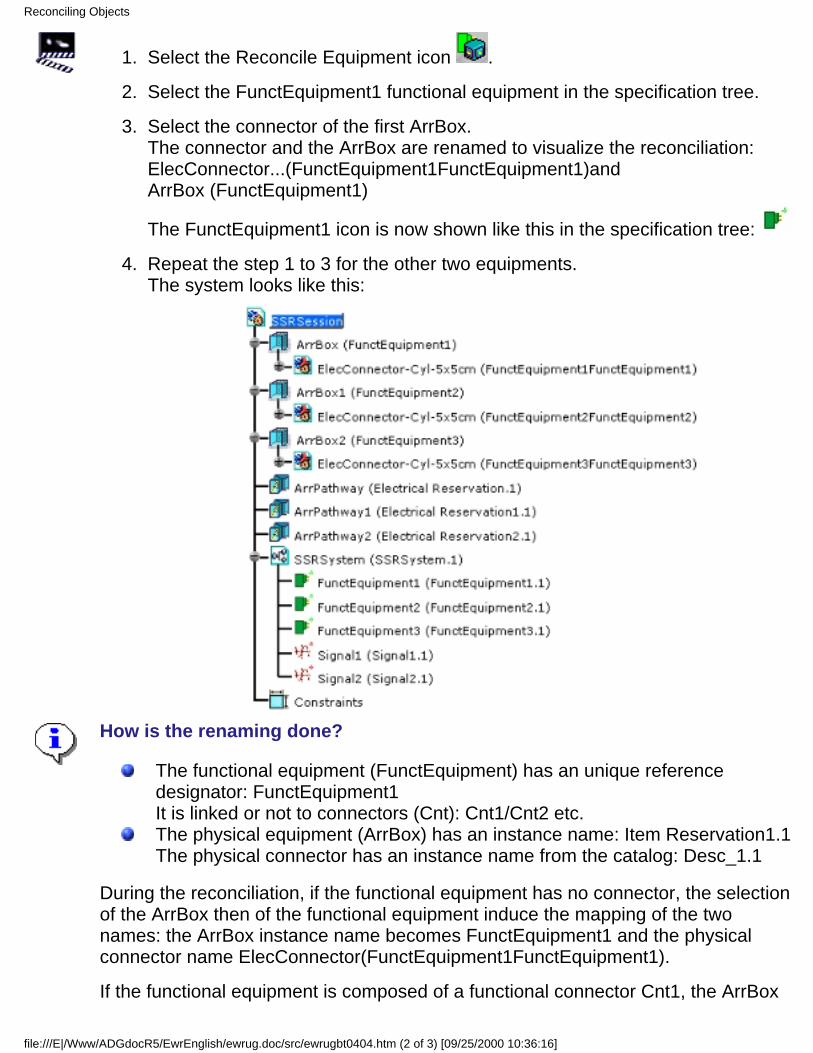
Select the Reconcile Equipment icon .1.
Select the FunctEquipment1 functional equipment in the specification tree.2.
Select the connector of the first ArrBox.The connector and the ArrBox are renamed to visualize the reconciliation:ElecConnector...(FunctEquipment1FunctEquipment1)andArrBox (FunctEquipment1)
The FunctEquipment1 icon is now shown like this in the specification tree:
3.
Repeat the step 1 to 3 for the other two equipments.The system looks like this:
4.
How is the renaming done?
The functional equipment (FunctEquipment) has an unique referencedesignator: FunctEquipment1It is linked or not to connectors (Cnt): Cnt1/Cnt2 etc.The physical equipment (ArrBox) has an instance name: Item Reservation1.1The physical connector has an instance name from the catalog: Desc_1.1
During the reconciliation, if the functional equipment has no connector, the selectionof the ArrBox then of the functional equipment induce the mapping of the twonames: the ArrBox instance name becomes FunctEquipment1 and the physicalconnector name ElecConnector(FunctEquipment1FunctEquipment1).
If the functional equipment is composed of a functional connector Cnt1, the ArrBox
Reconciling Objects
file:///E|/Www/ADGdocR5/EwrEnglish/ewrug.doc/src/ewrugbt0404.htm (2 of 3) [09/25/2000 10:36:16]

instance name becomes FunctEquipment1 and the physical connector nameElecConnector(Cnt1).
A functional equipment which is not reconciled with a physical connector is shown
like this:
After reconciliation, it becomes:
Reconciling Objects
file:///E|/Www/ADGdocR5/EwrEnglish/ewrug.doc/src/ewrugbt0404.htm (3 of 3) [09/25/2000 10:36:16]
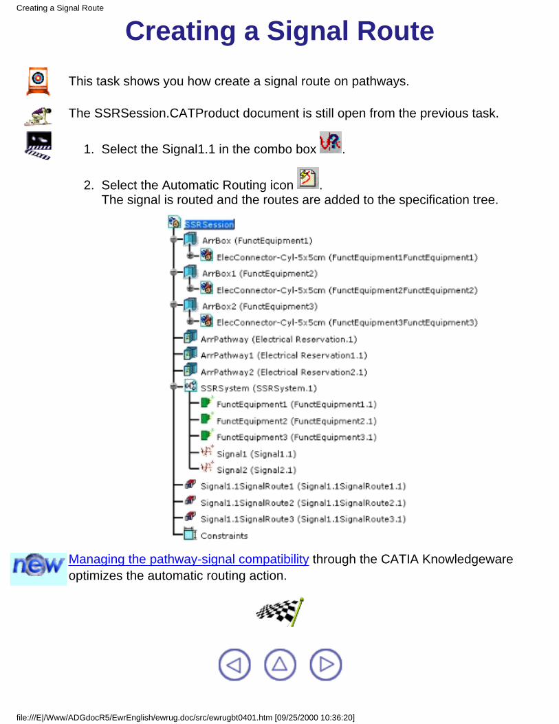
Creating a Signal RouteThis task shows you how create a signal route on pathways.
The SSRSession.CATProduct document is still open from the previous task.
Select the Signal1.1 in the combo box .1.
Select the Automatic Routing icon .The signal is routed and the routes are added to the specification tree.
2.
Managing the pathway-signal compatibility through the CATIA Knowledgewareoptimizes the automatic routing action.
Creating a Signal Route
file:///E|/Www/ADGdocR5/EwrEnglish/ewrug.doc/src/ewrugbt0401.htm [09/25/2000 10:36:20]

Deleting a Signal RouteThis task shows you how to delete a signal route.
The SSRSession.CATProduct document is still open from the previous task.
Select the signal route to be deleted in the specification tree: SignalRoute21.
Press the Delete key or right-click to use the contextual menu: -> Delete.2.
The signal route is deleted.
Deleting a Signal Route
file:///E|/Www/ADGdocR5/EwrEnglish/ewrug.doc/src/ewrugbt0402.htm [09/25/2000 10:36:24]
Working with Wire Connections
Create a connection on the active bundle to link several wires of a same signal.
Move a connection to the segment other extremity. The wires will be resized.
Deleting a connection links the wires.
Working with Wire Connections
file:///E|/Www/ADGdocR5/EwrEnglish/ewrug.doc/src/ewrugbt0500.htm [09/25/2000 10:36:28]
Creating a Wire Connection(Manual Mode)
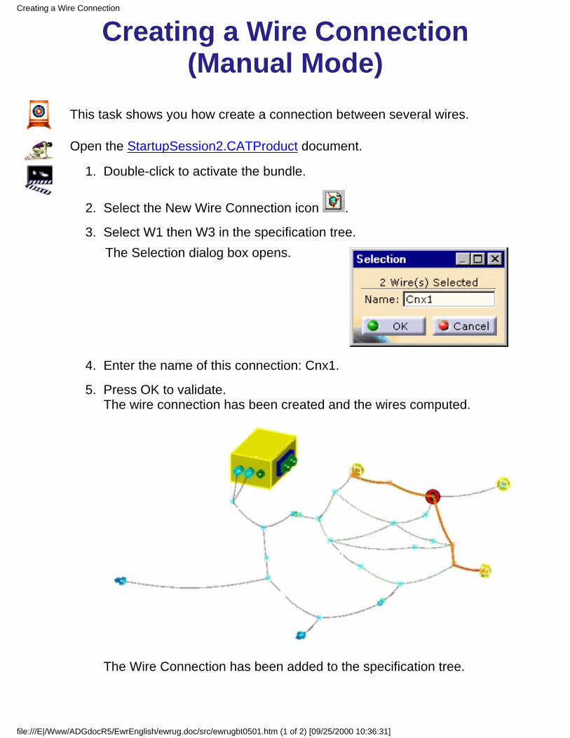
This task shows you how create a connection between several wires.
Open the StartupSession2.CATProduct document.
Double-click to activate the bundle.1.
Select the New Wire Connection icon .2.
Select W1 then W3 in the specification tree.The Selection dialog box opens.
3.
Enter the name of this connection: Cnx1.4.
Press OK to validate.The wire connection has been created and the wires computed.
The Wire Connection has been added to the specification tree.
5.
Creating a Wire Connection
file:///E|/Www/ADGdocR5/EwrEnglish/ewrug.doc/src/ewrugbt0501.htm (1 of 2) [09/25/2000 10:36:31]
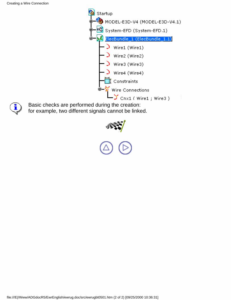
Basic checks are performed during the creation:for example, two different signals cannot be linked.
Creating a Wire Connection
file:///E|/Www/ADGdocR5/EwrEnglish/ewrug.doc/src/ewrugbt0501.htm (2 of 2) [09/25/2000 10:36:31]
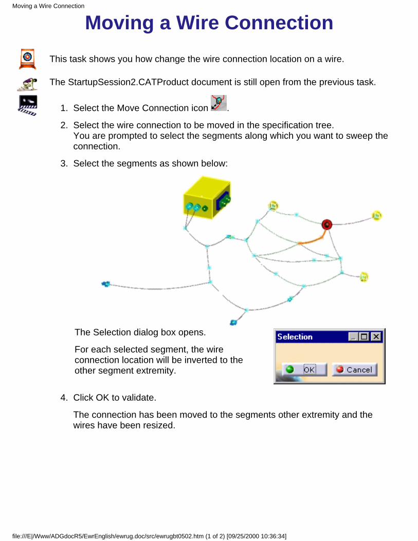
Moving a Wire ConnectionThis task shows you how change the wire connection location on a wire.
The StartupSession2.CATProduct document is still open from the previous task.
Select the Move Connection icon .1.
Select the wire connection to be moved in the specification tree.You are prompted to select the segments along which you want to sweep theconnection.
2.
Select the segments as shown below:
The Selection dialog box opens.
For each selected segment, the wireconnection location will be inverted to theother segment extremity.
3.
Click OK to validate.4.
The connection has been moved to the segments other extremity and thewires have been resized.
Moving a Wire Connection
file:///E|/Www/ADGdocR5/EwrEnglish/ewrug.doc/src/ewrugbt0502.htm (1 of 2) [09/25/2000 10:36:34]
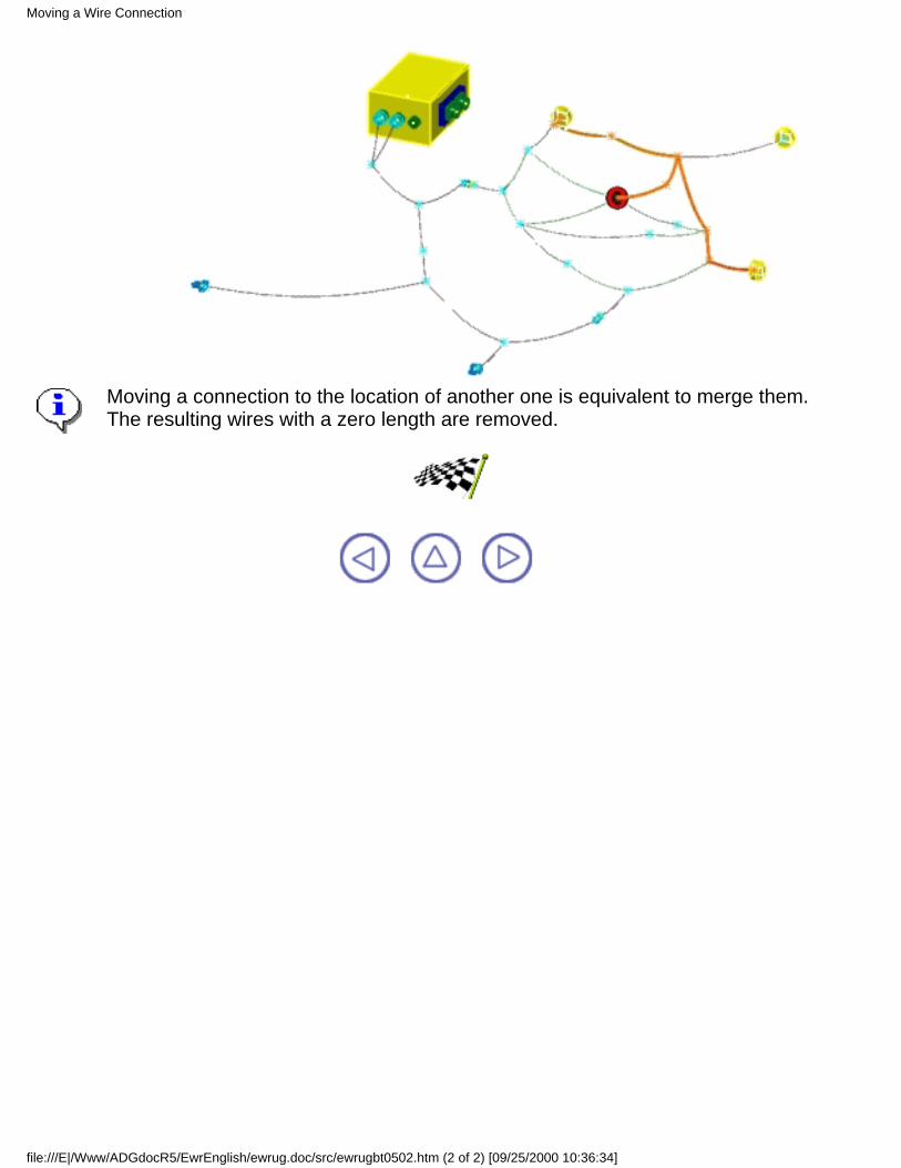
Moving a connection to the location of another one is equivalent to merge them.The resulting wires with a zero length are removed.
Moving a Wire Connection
file:///E|/Www/ADGdocR5/EwrEnglish/ewrug.doc/src/ewrugbt0502.htm (2 of 2) [09/25/2000 10:36:34]
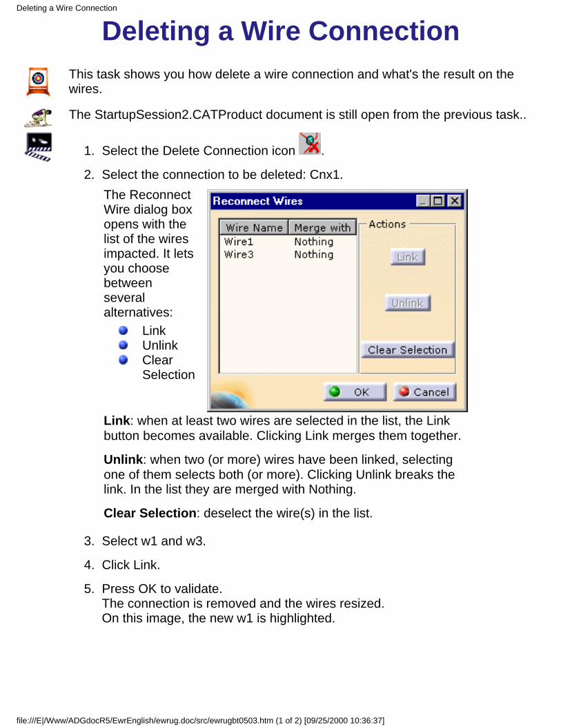
Deleting a Wire ConnectionThis task shows you how delete a wire connection and what's the result on thewires.
The StartupSession2.CATProduct document is still open from the previous task..
Select the Delete Connection icon .1.
Select the connection to be deleted: Cnx1.The ReconnectWire dialog boxopens with thelist of the wiresimpacted. It letsyou choosebetweenseveralalternatives:
LinkUnlinkClearSelection
Link: when at least two wires are selected in the list, the Linkbutton becomes available. Clicking Link merges them together.
Unlink: when two (or more) wires have been linked, selectingone of them selects both (or more). Clicking Unlink breaks thelink. In the list they are merged with Nothing.
Clear Selection: deselect the wire(s) in the list.
2.
Select w1 and w3.3.
Click Link.4.
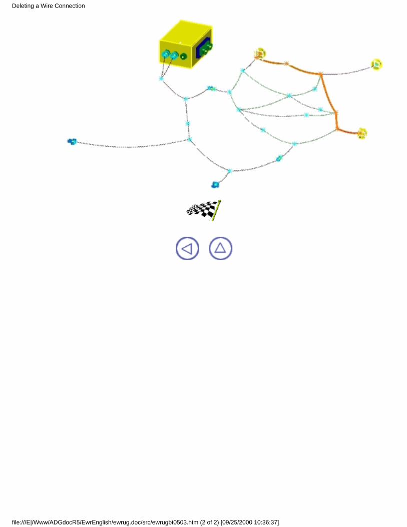
Press OK to validate.The connection is removed and the wires resized.On this image, the new w1 is highlighted.
5.
Deleting a Wire Connection
file:///E|/Www/ADGdocR5/EwrEnglish/ewrug.doc/src/ewrugbt0503.htm (1 of 2) [09/25/2000 10:36:37]
Deleting a Wire Connection
file:///E|/Www/ADGdocR5/EwrEnglish/ewrug.doc/src/ewrugbt0503.htm (2 of 2) [09/25/2000 10:36:37]
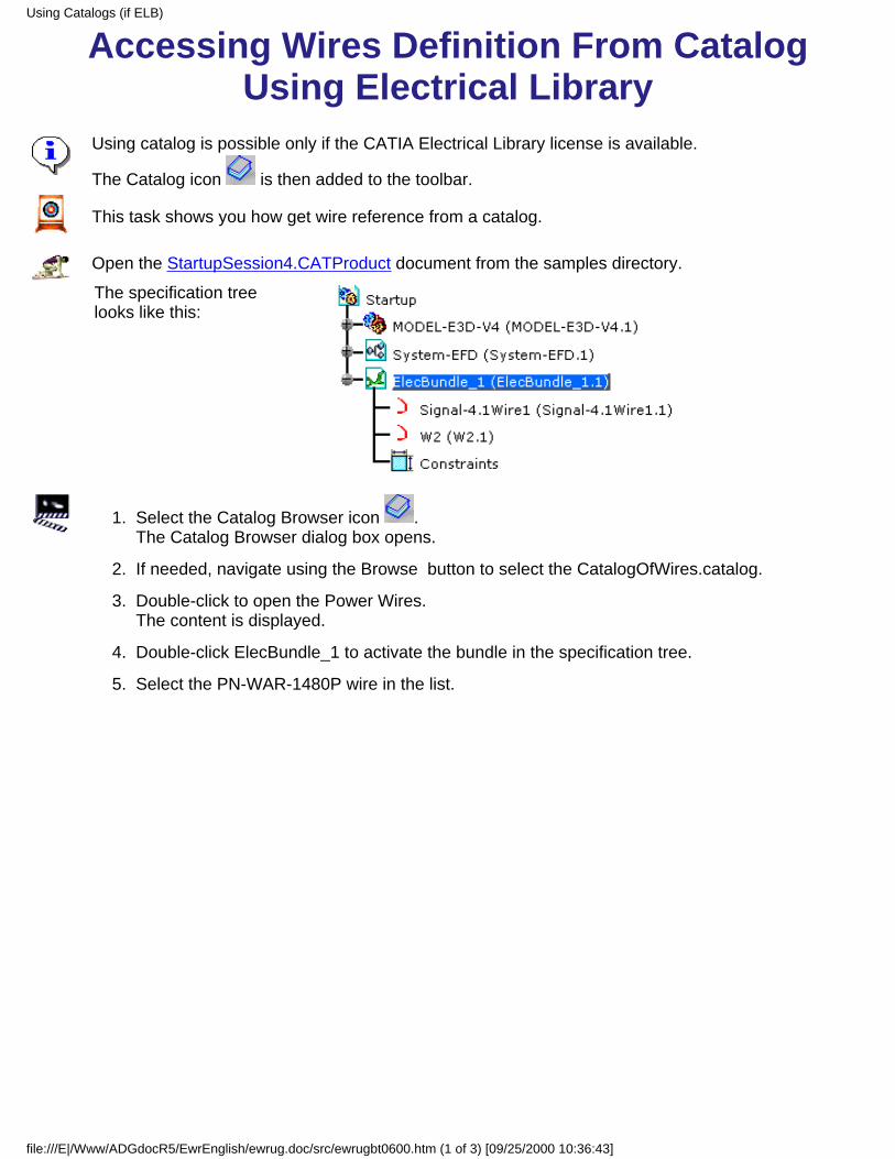
Accessing Wires Definition From CatalogUsing Electrical Library
Using catalog is possible only if the CATIA Electrical Library license is available.
The Catalog icon is then added to the toolbar.
This task shows you how get wire reference from a catalog.
Open the StartupSession4.CATProduct document from the samples directory.
The specification treelooks like this:
Select the Catalog Browser icon .The Catalog Browser dialog box opens.
1.
If needed, navigate using the Browse button to select the CatalogOfWires.catalog.2.
Double-click to open the Power Wires.The content is displayed.
3.
Double-click ElecBundle_1 to activate the bundle in the specification tree.4.
Select the PN-WAR-1480P wire in the list.5.
Using Catalogs (if ELB)
file:///E|/Www/ADGdocR5/EwrEnglish/ewrug.doc/src/ewrugbt0600.htm (1 of 3) [09/25/2000 10:36:43]
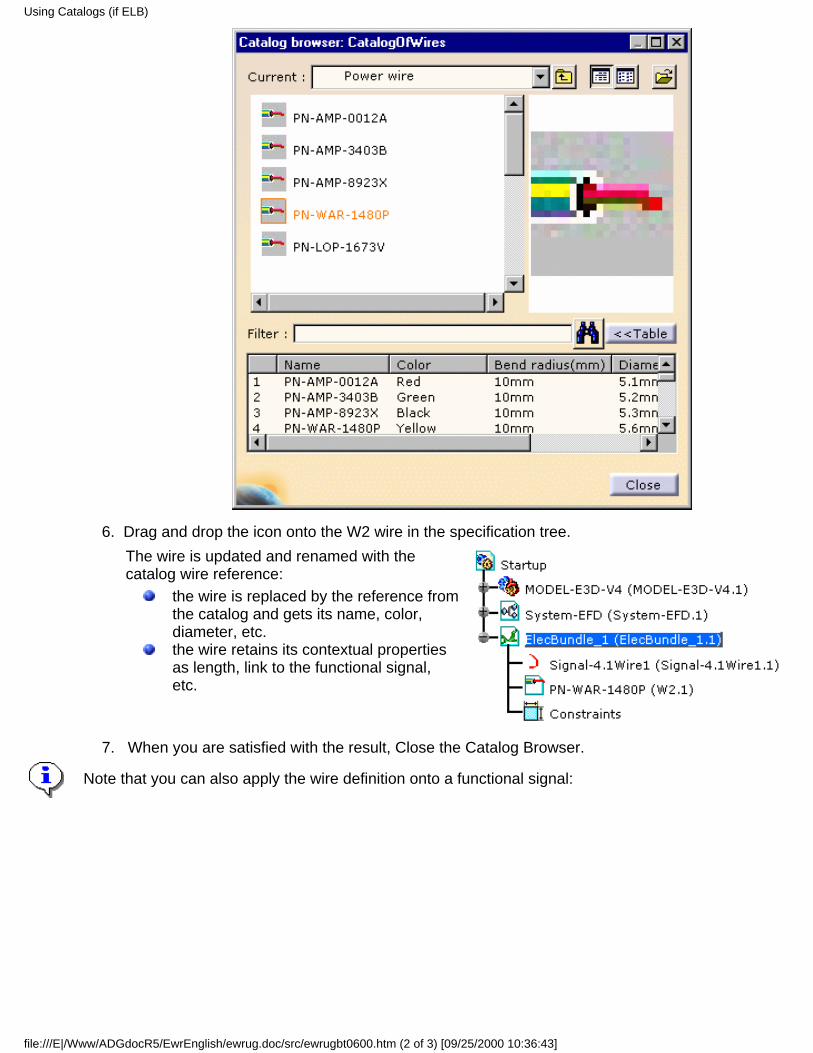
Drag and drop the icon onto the W2 wire in the specification tree.The wire is updated and renamed with thecatalog wire reference:
the wire is replaced by the reference fromthe catalog and gets its name, color,diameter, etc.the wire retains its contextual propertiesas length, link to the functional signal,etc.
6.
When you are satisfied with the result, Close the Catalog Browser.7.
Note that you can also apply the wire definition onto a functional signal:
Using Catalogs (if ELB)
file:///E|/Www/ADGdocR5/EwrEnglish/ewrug.doc/src/ewrugbt0600.htm (2 of 3) [09/25/2000 10:36:43]
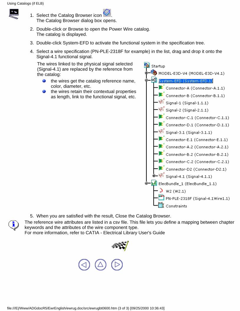
Select the Catalog Browser icon .The Catalog Browser dialog box opens.
1.
Double-click or Browse to open the Power Wire catalog.The catalog is displayed.
2.
Double-click System-EFD to activate the functional system in the specification tree.3.
Select a wire specification (PN-PLE-2318F for example) in the list, drag and drop it onto theSignal-4.1 functional signal.The wires linked to the physical signal selected(Signal-4.1) are replaced by the reference fromthe catalog:
the wires get the catalog reference name,color, diameter, etc.the wires retain their contextual propertiesas length, link to the functional signal, etc.
4.
When you are satisfied with the result, Close the Catalog Browser.5. The reference wire attributes are listed in a csv file. This file lets you define a mapping between chapterkeywords and the attributes of the wire component type.For more information, refer to CATIA - Electrical Library User's Guide
Using Catalogs (if ELB)
file:///E|/Www/ADGdocR5/EwrEnglish/ewrug.doc/src/ewrugbt0600.htm (3 of 3) [09/25/2000 10:36:43]

V4 InteroperabilityThis task explains how to work with CATIA Version 4 using data from CATIA Version5.
Open the StartupSession1.CATProduct document.
When you are in the Electrical Wire Routing workbench, the Export Wires... item isadded to the Tools Menu.
Select the Signal 1.1.1 in the combo box.1.
Double-click the bundle to activate it.2.
Click the Automatic Routing icon .The signal is routed and the wires have been added to the specification tree.
3.
Choose the Tools -> Export Wires... menu item.The File dialog box opens:
4.
Enter the name of the file.5.
Click OK to validate.A .csv file is created with the specification of the wires, as shown below.
6.
V4 Interoperability
file:///E|/Www/ADGdocR5/EwrEnglish/ewrug.doc/src/ewrugbt0700.htm (1 of 2) [09/25/2000 10:36:53]
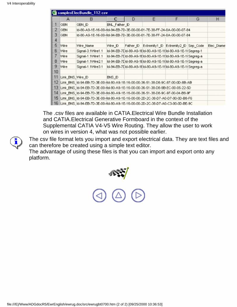
The .csv files are available in CATIA.Electrical Wire Bundle Installationand CATIA.Electrical Generative Formboard in the context of theSupplemental CATIA V4-V5 Wire Routing. They allow the user to workon wires in version 4, what was not possible earlier.
The csv file format lets you import and export electrical data. They are text files andcan therefore be created using a simple text editor.The advantage of using these files is that you can import and export onto anyplatform.
V4 Interoperability
file:///E|/Www/ADGdocR5/EwrEnglish/ewrug.doc/src/ewrugbt0700.htm (2 of 2) [09/25/2000 10:36:53]

VPM1 InteroperabilityUsing VPM1 is possible only if the CATIA - V4 Integration license is available and if you work on UNIX platform.The VPM1 toolbar then is added to the workbench. For more information about VPM1 Interoperability, refer toBuilding a CATIA V5 Product from a VPM1 PSN Window in CATIA - V4 Integration.
This task explains how to save CATIA Version 5 electrical data in VPM1.
Before performing this scenario, the following documents, provided in the samples directory, have to be stored inVPM1 using the standard functionalities of VPM1 interoperability:
Bundle.CATProductSystem-Sample.CATProductMODEL-V4-ELECTRICAL-SAMPLE.model
Make sure that the appropriate windows in both VPM1 and CATIA are active each time you perform anoperation.
Launch VPM1.1.
Run the PSN on the branch where the three documents have been saved.2.
Expand the branch and you should get:3.
In this window, select the .CATProduct documents and the model to open them with CATIA V5.The session is built:
4.
VPM1 Interoperability
file:///E|/Www/ADGdocR5/EwrEnglish/ewrug.doc/src/ewrugbt0800.htm (1 of 3) [09/25/2000 10:36:57]
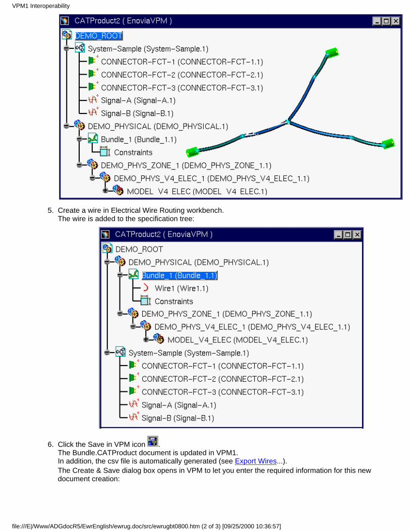
Create a wire in Electrical Wire Routing workbench.The wire is added to the specification tree:
5.
Click the Save in VPM icon .The Bundle.CATProduct document is updated in VPM1.In addition, the csv file is automatically generated (see Export Wires...).The Create & Save dialog box opens in VPM to let you enter the required information for this newdocument creation:
6.
VPM1 Interoperability
file:///E|/Www/ADGdocR5/EwrEnglish/ewrug.doc/src/ewrugbt0800.htm (2 of 3) [09/25/2000 10:36:57]
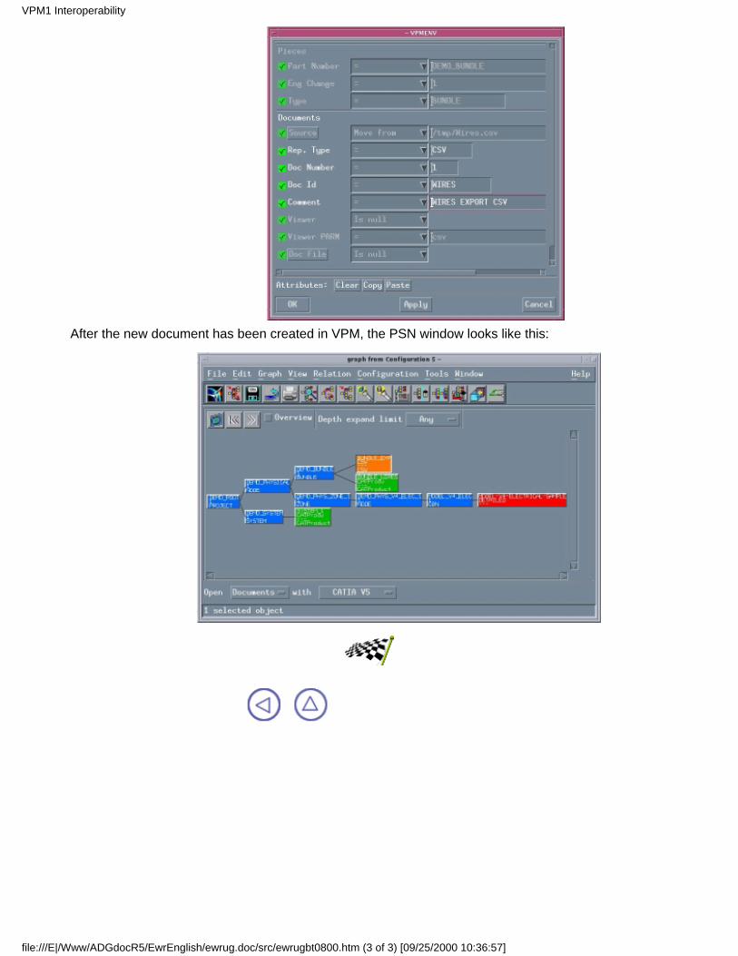
After the new document has been created in VPM, the PSN window looks like this:
VPM1 Interoperability
file:///E|/Www/ADGdocR5/EwrEnglish/ewrug.doc/src/ewrugbt0800.htm (3 of 3) [09/25/2000 10:36:57]

Advanced TasksThe Advanced Tasks you will perform in the Electrical Wire Routing workbench involve wireconnection capabilities and routing simulation.The table below lists the information you will find.
Working with Wire ConnectionsWire Extremity Management
Routing SimulationManaging Pathway/Signal Compatibility during Automatic Routing with Knowledgeware
Advanced Tasks
file:///E|/Www/ADGdocR5/EwrEnglish/ewrug.doc/src/ewrugat0000.htm [09/25/2000 10:37:15]
Working with Wire Connections
Merging Wire Connections: Create a unique connection, linking wires from severalconnections located at the same place.Splitting a Wire Connection: Create several connections and reconnect the wires.
Working with Wire Connections
file:///E|/Www/ADGdocR5/EwrEnglish/ewrug.doc/src/ewrugat0100.htm [09/25/2000 10:37:16]
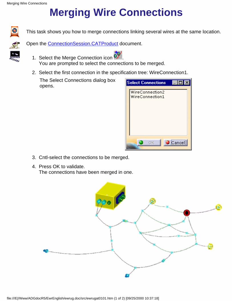
Merging Wire ConnectionsThis task shows you how to merge connections linking several wires at the same location.
Open the ConnectionSession.CATProduct document.
Select the Merge Connection icon .You are prompted to select the connections to be merged.
1.
Select the first connection in the specification tree: WireConnection1.The Select Connections dialog boxopens.
2.
Cntl-select the connections to be merged.3.
Press OK to validate.The connections have been merged in one.
4.
Merging Wire Connections
file:///E|/Www/ADGdocR5/EwrEnglish/ewrug.doc/src/ewrugat0101.htm (1 of 2) [09/25/2000 10:37:18]
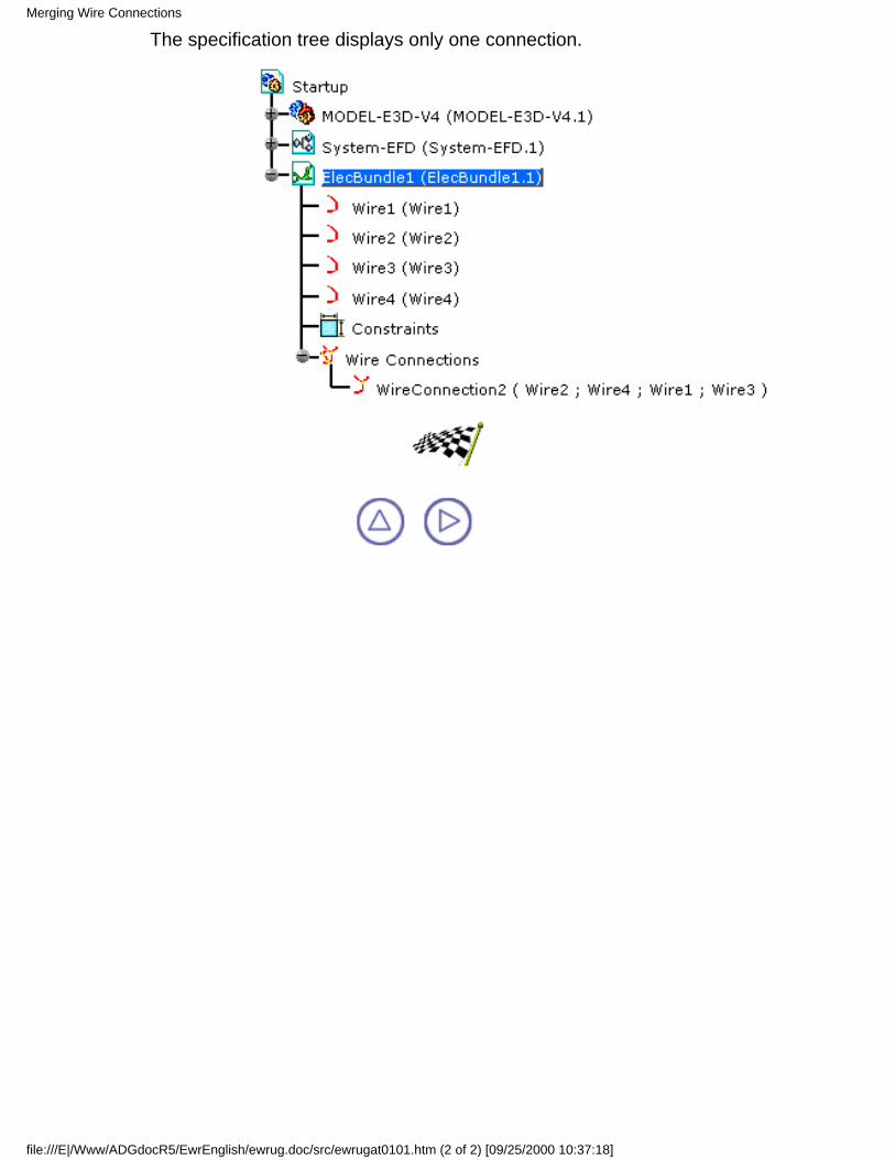
The specification tree displays only one connection.
Merging Wire Connections
file:///E|/Www/ADGdocR5/EwrEnglish/ewrug.doc/src/ewrugat0101.htm (2 of 2) [09/25/2000 10:37:18]
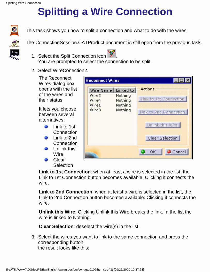
Splitting a Wire ConnectionThis task shows you how to split a connection and what to do with the wires.
The ConnectionSession.CATProduct document is still open from the previous task.
Select the Split Connection icon .You are prompted to select the connection to be split.
1.
Select WireConection2.The ReconnectWires dialog boxopens with the listof the wires andtheir status.
It lets you choosebetween severalalternatives:
Link to 1stConnectionLink to 2ndConnectionUnlink thisWireClearSelection
Link to 1st Connection: when at least a wire is selected in the list, theLink to 1st Connection button becomes available. Clicking it connects thewire.
Link to 2nd Connection: when at least a wire is selected in the list, theLink to 2nd Connection button becomes available. Clicking it connects thewire.
Unlink this Wire: Clicking Unlink this Wire breaks the link. In the list thewire is linked to Nothing.
Clear Selection: deselect the wire(s) in the list.
2.
Select the wires you want to link to the same connection and press thecorresponding button.the result looks like this:
3.
Splitting Wire Connection
file:///E|/Www/ADGdocR5/EwrEnglish/ewrug.doc/src/ewrugat0102.htm (1 of 3) [09/25/2000 10:37:23]
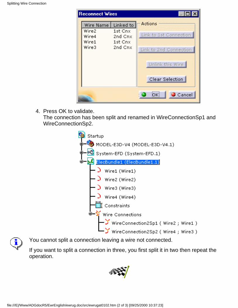
Press OK to validate.The connection has been split and renamed in WireConnectionSp1 andWireConnectionSp2.
4.
You cannot split a connection leaving a wire not connected.
If you want to split a connection in three, you first split it in two then repeat theoperation.
Splitting Wire Connection
file:///E|/Www/ADGdocR5/EwrEnglish/ewrug.doc/src/ewrugat0102.htm (2 of 3) [09/25/2000 10:37:23]

Splitting Wire Connection
file:///E|/Www/ADGdocR5/EwrEnglish/ewrug.doc/src/ewrugat0102.htm (3 of 3) [09/25/2000 10:37:23]
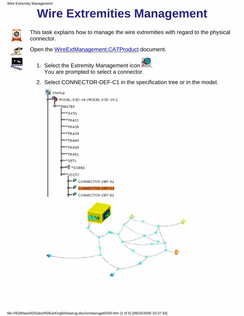
Wire Extremities ManagementThis task explains how to manage the wire extremities with regard to the physicalconnector.
Open the WireExtManagement.CATProduct document.
Select the Extremity Management icon .You are prompted to select a connector.
1.
Select CONNECTOR-DEF-C1 in the specification tree or in the model.2.
Wire Extremity Management
file:///E|/Www/ADGdocR5/EwrEnglish/ewrug.doc/src/ewrugat0200.htm (1 of 6) [09/25/2000 10:37:34]
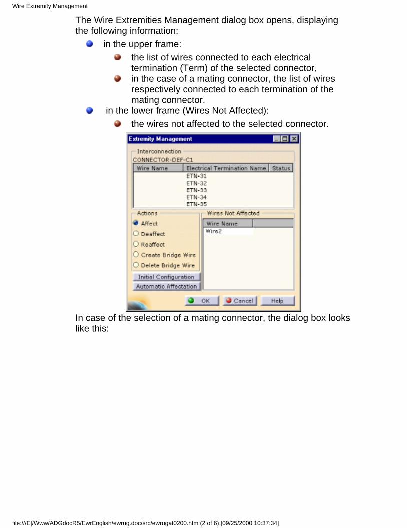
The Wire Extremities Management dialog box opens, displayingthe following information:
in the upper frame:the list of wires connected to each electricaltermination (Term) of the selected connector,in the case of a mating connector, the list of wiresrespectively connected to each termination of themating connector.
in the lower frame (Wires Not Affected):the wires not affected to the selected connector.
In case of the selection of a mating connector, the dialog box lookslike this:
Wire Extremity Management
file:///E|/Www/ADGdocR5/EwrEnglish/ewrug.doc/src/ewrugat0200.htm (2 of 6) [09/25/2000 10:37:34]

Let's see the different commands available:AffectDeaffectReaffectCreate Bridge WireDelete Bridge Wire
All these commands respect the signal continuity principle,that is to say that it is not possible to connect two or morewires which are not belonging to the same signal.
The Affect command is selected.
Select the wire in the lower frame: Wire23.
Select an electrical termination in the upper frame:The wire is affected to theconnector onto thistermination.
4.
Select the Reaffect command.5.
Wire Extremity Management
file:///E|/Www/ADGdocR5/EwrEnglish/ewrug.doc/src/ewrugat0200.htm (3 of 6) [09/25/2000 10:37:34]
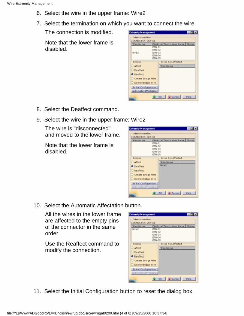
Select the wire in the upper frame: Wire26.
Select the termination on which you want to connect the wire.The connection is modified.
Note that the lower frame isdisabled.
7.
Select the Deaffect command.8.
Select the wire in the upper frame: Wire2The wire is "disconnected"and moved to the lower frame.
Note that the lower frame isdisabled.
9.
Select the Automatic Affectation button.All the wires in the lower frameare affected to the empty pinsof the connector in the sameorder.
Use the Reaffect command tomodify the connection.
10.
Select the Initial Configuration button to reset the dialog box.11.
Wire Extremity Management
file:///E|/Www/ADGdocR5/EwrEnglish/ewrug.doc/src/ewrugat0200.htm (4 of 6) [09/25/2000 10:37:34]

Select the Create Bridge Wire button.12.
Select the two terminations you want to be linked using Ctrl key.It is possible to create a bridge wire between two terminations alreadyaffected with wires belonging to the same signal or between atermination containing wires and an empty one.
The Create Bridge Wire dialog box opens displaying a default name.
In case of the selection of a mating connector, the radio buttons indicate onwhich side you want the bridge wire to be created.The dialog box looks like this:
13.
Change the Wire Name if need be and click OK to validate.The bridge wire is added tothe list onto thecorrespondingterminations.
14.
Wire Extremity Management
file:///E|/Www/ADGdocR5/EwrEnglish/ewrug.doc/src/ewrugat0200.htm (5 of 6) [09/25/2000 10:37:34]
To delete the bridge wire, click the Delete Bridge Wire button and selectBridgeWire3 in the list.
15.
When you are satisfied with your choice, press OK to validate.16.
Wire Extremity Management
file:///E|/Www/ADGdocR5/EwrEnglish/ewrug.doc/src/ewrugat0200.htm (6 of 6) [09/25/2000 10:37:34]
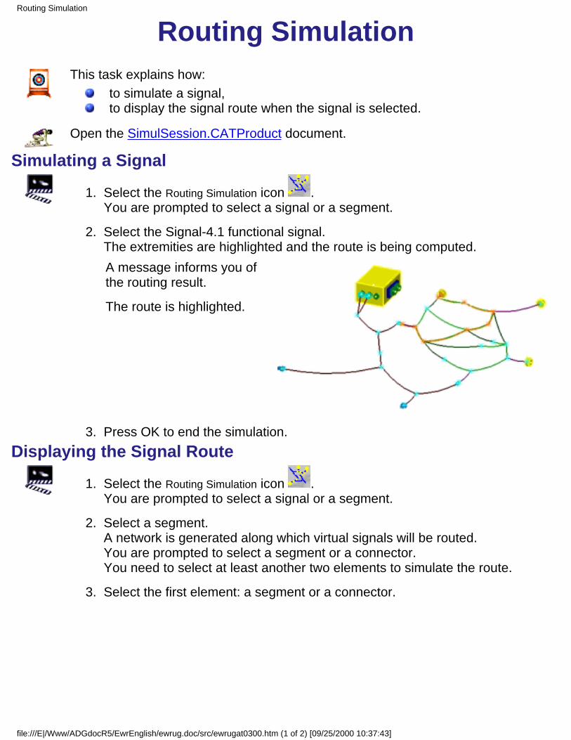
Routing SimulationThis task explains how:
to simulate a signal,to display the signal route when the signal is selected.
Open the SimulSession.CATProduct document.
Simulating a Signal
Select the Routing Simulation icon .You are prompted to select a signal or a segment.
1.
Select the Signal-4.1 functional signal.The extremities are highlighted and the route is being computed.A message informs you ofthe routing result.
The route is highlighted.
2.
Press OK to end the simulation.3. Displaying the Signal Route
Select the Routing Simulation icon .You are prompted to select a signal or a segment.
1.
Select a segment.A network is generated along which virtual signals will be routed.You are prompted to select a segment or a connector.You need to select at least another two elements to simulate the route.
2.
Select the first element: a segment or a connector.3.
Routing Simulation
file:///E|/Www/ADGdocR5/EwrEnglish/ewrug.doc/src/ewrugat0300.htm (1 of 2) [09/25/2000 10:37:43]

The Routing Simulation dialog boxopens.
The Section and Separation Code fields allow you to define selection criteria.This information is optional. The compatibility table contains the separationcodes of the wires and is customizable in the settings.
Select the second element: a segment or a connector.The virtual signal may have multiple extremities.The Compute button is enabled.
4.
Press Compute to simulate the route.The route is highlighted.
5.
Press New Extremities to create a new virtual signal.You are prompted to select other segments or connectors.
6.
When you are satisfied with your choice, click Compute again.The new route is highlighted.
7.
Press Close to end the simulation.8.
Routing Simulation
file:///E|/Www/ADGdocR5/EwrEnglish/ewrug.doc/src/ewrugat0300.htm (2 of 2) [09/25/2000 10:37:43]

Managing Pathway/SignalCompatibility
During Automatic Routing withKnowledgeware
This task explains how to manage pathway/signal compatibility using CATIAknowledgeware.Open the SessionPlane document. It represents the wiring of a plane, consisting of alight system and of pathways and connection boxes. You should be fluent withCATIA Knowledge.By default, signals are routed according to their rank and priorities, using theshortest available route, according to the list below.
Through the options, you can choose to route all signals or some of them, and torespect priorities or not. For more information, see Routing a Wire.
You can define additional rules in the Tools, Options ... menu. For more information,see Customizing. These rules are used to define compatibilities between signals orbetween signals and arcs and to optimize the automatic routing. For example here isa Signal-Arc rule:
Managing Pathway/Signal Compatibility during Automatic Routing with Knowledgeware
file:///E|/Www/ADGdocR5/EwrEnglish/ewrug.doc/src/ewrugat0400.htm (1 of 2) [09/25/2000 10:37:47]
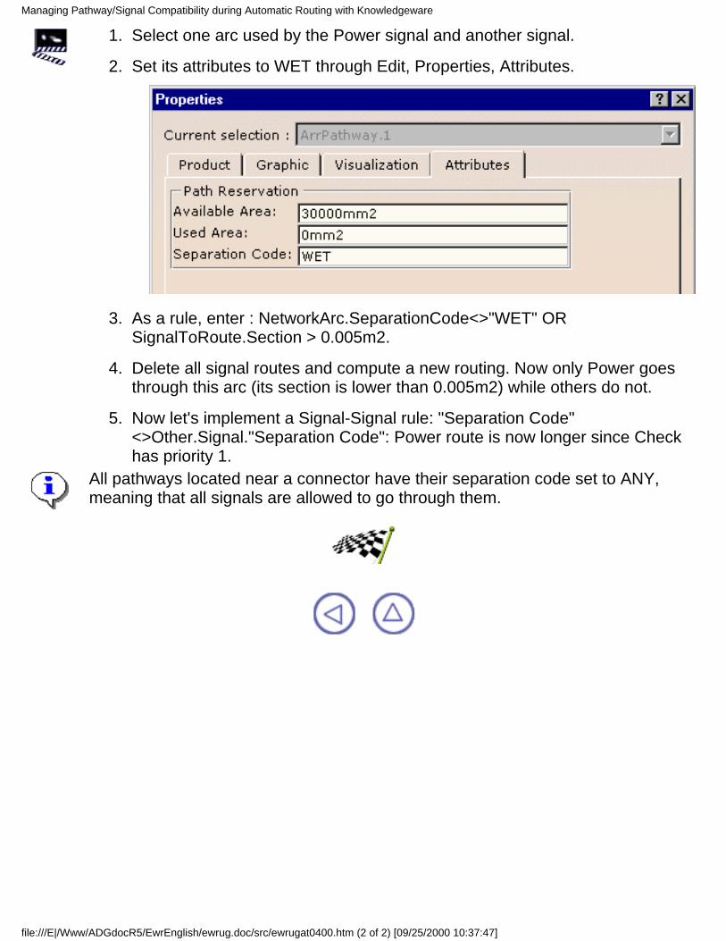
Select one arc used by the Power signal and another signal.1.
Set its attributes to WET through Edit, Properties, Attributes.2.
As a rule, enter : NetworkArc.SeparationCode<>"WET" ORSignalToRoute.Section > 0.005m2.
3.
Delete all signal routes and compute a new routing. Now only Power goesthrough this arc (its section is lower than 0.005m2) while others do not.
4.
Now let's implement a Signal-Signal rule: "Separation Code"<>Other.Signal."Separation Code": Power route is now longer since Checkhas priority 1.
5.
All pathways located near a connector have their separation code set to ANY,meaning that all signals are allowed to go through them.
Managing Pathway/Signal Compatibility during Automatic Routing with Knowledgeware
file:///E|/Www/ADGdocR5/EwrEnglish/ewrug.doc/src/ewrugat0400.htm (2 of 2) [09/25/2000 10:37:47]
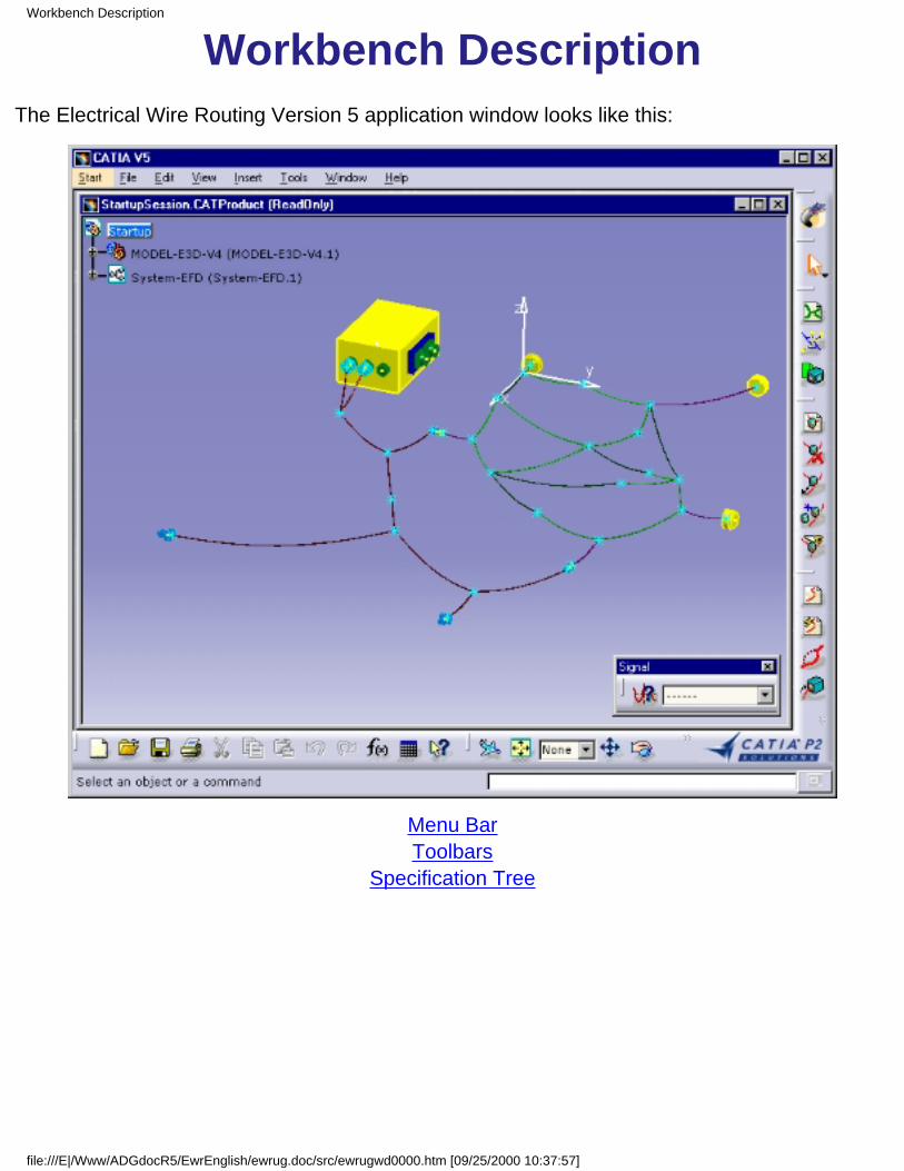
Workbench DescriptionThe Electrical Wire Routing Version 5 application window looks like this:
Menu BarToolbars
Specification Tree
Workbench Description
file:///E|/Www/ADGdocR5/EwrEnglish/ewrug.doc/src/ewrugwd0000.htm [09/25/2000 10:37:57]
Menu BarThe Menu Bar and most of the items available in CATIA - Electrical Wire Routing workbenchare the standard ones. The different commands and tools are described in CATIA -Infrastructure Version 5. For more information, refer to the CATIA Menu Bar section.
However one item is added to the Tools menu: Export Wires...Refer to V4 Interoperability.
Menu Bar
file:///E|/Www/ADGdocR5/EwrEnglish/ewrug.doc/src/ewrugwd0100.htm [09/25/2000 10:38:00]
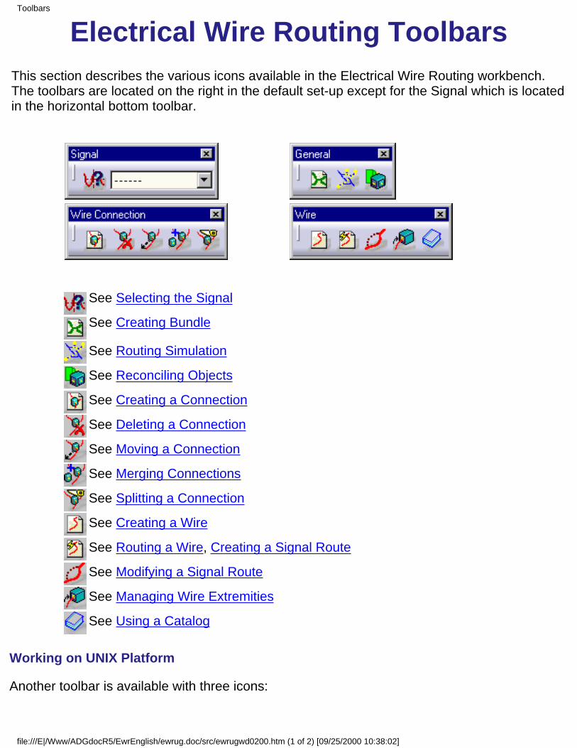
Electrical Wire Routing ToolbarsThis section describes the various icons available in the Electrical Wire Routing workbench.The toolbars are located on the right in the default set-up except for the Signal which is locatedin the horizontal bottom toolbar.
See Selecting the Signal
See Creating Bundle
See Routing Simulation
See Reconciling Objects
See Creating a Connection
See Deleting a Connection
See Moving a Connection
See Merging Connections
See Splitting a Connection
See Creating a Wire
See Routing a Wire, Creating a Signal Route
See Modifying a Signal Route
See Managing Wire Extremities
See Using a Catalog
Working on UNIX Platform
Another toolbar is available with three icons:
Toolbars
file:///E|/Www/ADGdocR5/EwrEnglish/ewrug.doc/src/ewrugwd0200.htm (1 of 2) [09/25/2000 10:38:02]
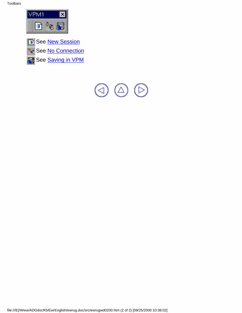
See New SessionSee No ConnectionSee Saving in VPM
Toolbars
file:///E|/Www/ADGdocR5/EwrEnglish/ewrug.doc/src/ewrugwd0200.htm (2 of 2) [09/25/2000 10:38:02]

Specification Tree
The Specification Tree displays the following icons:represents an electrical bundle, that is a document containing wires.
represents a wirerepresents a signal route
represents a constraint.
represents a set of wire connections
represents a connection
Specification Tree
file:///E|/Www/ADGdocR5/EwrEnglish/ewrug.doc/src/ewrugwd0300.htm [09/25/2000 10:38:08]

CustomizingBefore you start your first working session, you can customize the way you work to suit your habits, or to takeadvantage of CATIA knowledgeware. This is done using Tools -> Options, from the menu bar.
This type of customization is stored in permanent setting files. Settings will not be lost if you exit your session.Expand the Equipments & Systems tab in the options tree, and select the Electrical Wire Routingitem.The Options dialog box is displayed.
The General tab lets you customize the electrical equipment properties and the separationcode file access. You can also give a name to a property to display as a column title, andchange the Extremities color.
1.
The Favorites list contains the properties displayed in the Interconnection frame of the WireExtremities Management dialog box. To add properties to the list, select the property in theAvailable list and click the ---> arrow.
2.
To remove properties, do the reverse: select the property from the Favorites list and click the<--- arrow.
3.
Select a property in the Favorites list and enter a name in the Favorite column Title field.It is displayed in the Wire Connection Management dialog box:
4.
Customizing
file:///E|/Www/ADGdocR5/EwrEnglish/ewrug.doc/src/ewrugcu0000.htm (1 of 3) [09/25/2000 10:38:30]

Refer to Compatibility Table to know more about separation code.
The Separation Code File area is used to define Separation Code rules to optimize routing.See also Managing Pathway/Signal Compatibility during Automatic Routing withKnowledgeware.
8.
Those Separation Codes may be File Based. In that case, define the path to access thecompatibility table by clicking the Browse button to choose the separation code file. This fileis used during the Automatic Routing and the Routing Simulation.
9.
Two options are now available:10. Signal-Signal manages compatibility between signals,Signal-Arc manages compatibility between signal and pathways.
The Separation Codes may also be Rule Based, using CATIA Knowledgeware. Only one rulecan be implemented at a time, but this rule may combine several conditions. Push the Editbutton to enter a new rule. The Routing Rule Editor is displayed.
11.
Two options are now available:Signal-Signal manages compatibility between signals,Signal-Arc manages compatibility between signal and pathways.
Customizing
file:///E|/Www/ADGdocR5/EwrEnglish/ewrug.doc/src/ewrugcu0000.htm (2 of 3) [09/25/2000 10:38:30]
The line above the input field is a reminder of the knowledgeware syntax. The Erasericon is used to clean the input field.
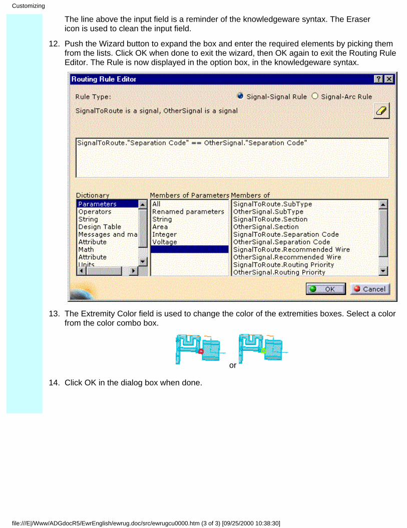
Push the Wizard button to expand the box and enter the required elements by picking themfrom the lists. Click OK when done to exit the wizard, then OK again to exit the Routing RuleEditor. The Rule is now displayed in the option box, in the knowledgeware syntax.
12.
The Extremity Color field is used to change the color of the extremities boxes. Select a colorfrom the color combo box.
or
13.
Click OK in the dialog box when done.14.
Customizing
file:///E|/Www/ADGdocR5/EwrEnglish/ewrug.doc/src/ewrugcu0000.htm (3 of 3) [09/25/2000 10:38:30]
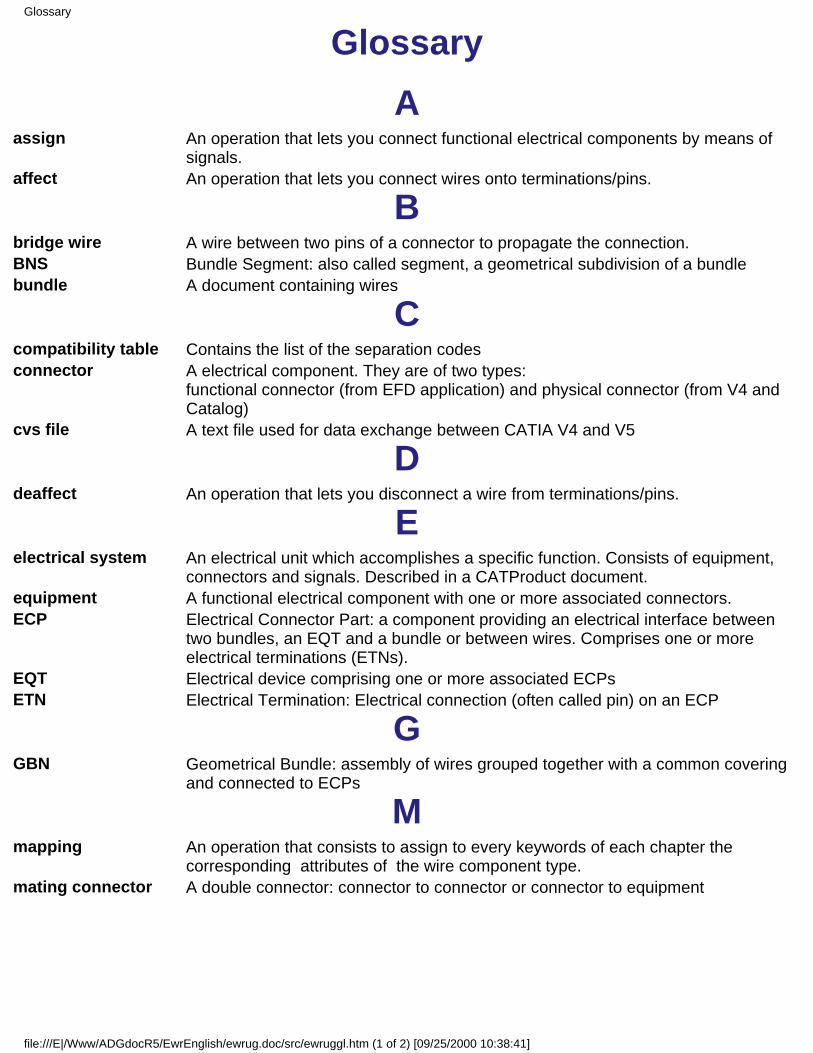
GlossaryA
assign An operation that lets you connect functional electrical components by means ofsignals.
affect An operation that lets you connect wires onto terminations/pins.
Bbridge wire A wire between two pins of a connector to propagate the connection.BNS Bundle Segment: also called segment, a geometrical subdivision of a bundlebundle A document containing wires
Ccompatibility table Contains the list of the separation codesconnector A electrical component. They are of two types:
functional connector (from EFD application) and physical connector (from V4 andCatalog)
cvs file A text file used for data exchange between CATIA V4 and V5
Ddeaffect An operation that lets you disconnect a wire from terminations/pins.
Eelectrical system An electrical unit which accomplishes a specific function. Consists of equipment,
connectors and signals. Described in a CATProduct document.equipment A functional electrical component with one or more associated connectors.ECP Electrical Connector Part: a component providing an electrical interface between
two bundles, an EQT and a bundle or between wires. Comprises one or moreelectrical terminations (ETNs).
EQT Electrical device comprising one or more associated ECPsETN Electrical Termination: Electrical connection (often called pin) on an ECP
GGBN Geometrical Bundle: assembly of wires grouped together with a common covering
and connected to ECPs
Mmapping An operation that consists to assign to every keywords of each chapter the
corresponding attributes of the wire component type.mating connector A double connector: connector to connector or connector to equipment
Glossary
file:///E|/Www/ADGdocR5/EwrEnglish/ewrug.doc/src/ewruggl.htm (1 of 2) [09/25/2000 10:38:41]
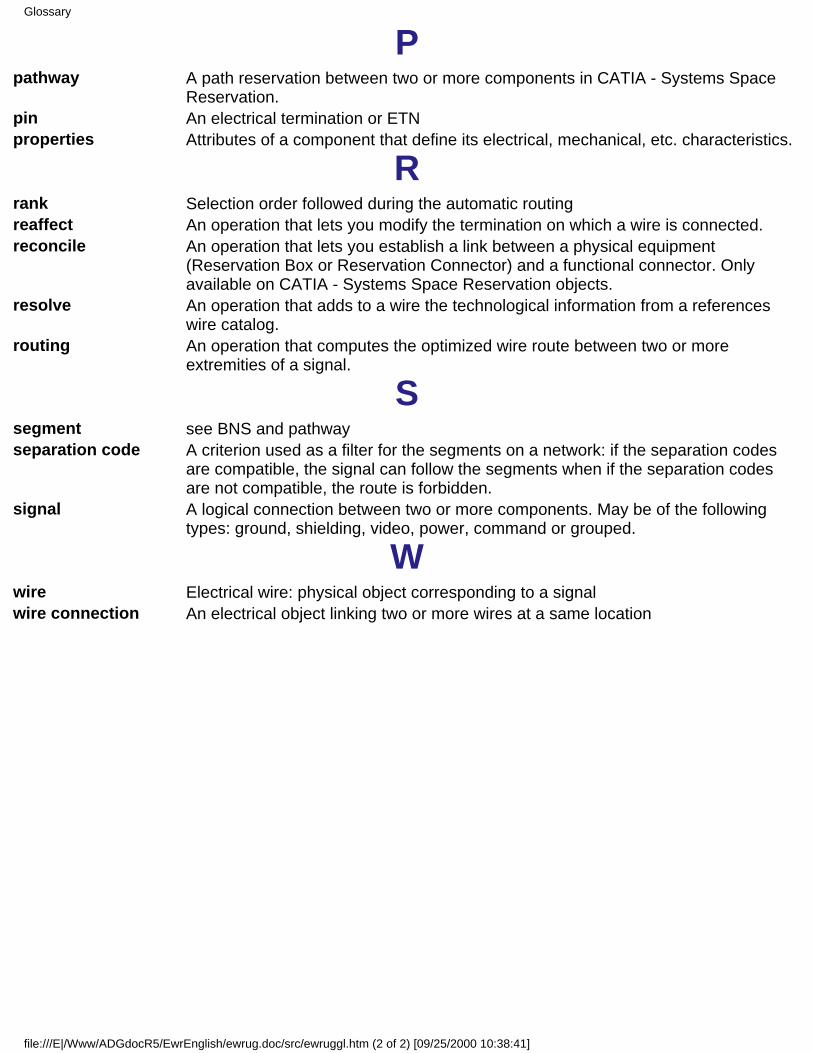
Ppathway A path reservation between two or more components in CATIA - Systems Space
Reservation.pin An electrical termination or ETNproperties Attributes of a component that define its electrical, mechanical, etc. characteristics.
Rrank Selection order followed during the automatic routingreaffect An operation that lets you modify the termination on which a wire is connected.reconcile An operation that lets you establish a link between a physical equipment
(Reservation Box or Reservation Connector) and a functional connector. Onlyavailable on CATIA - Systems Space Reservation objects.
resolve An operation that adds to a wire the technological information from a referenceswire catalog.
routing An operation that computes the optimized wire route between two or moreextremities of a signal.
Ssegment see BNS and pathwayseparation code A criterion used as a filter for the segments on a network: if the separation codes
are compatible, the signal can follow the segments when if the separation codesare not compatible, the route is forbidden.
signal A logical connection between two or more components. May be of the followingtypes: ground, shielding, video, power, command or grouped.
Wwire Electrical wire: physical object corresponding to a signalwire connection An electrical object linking two or more wires at a same location
Glossary
file:///E|/Www/ADGdocR5/EwrEnglish/ewrug.doc/src/ewruggl.htm (2 of 2) [09/25/2000 10:38:41]

IndexA
affect Arrangement Box ArrBox automatic routing
Bbridge wire bundle
Ccatalog compatibility table connection connector context csv file
Ddeaffect
EECP EQT equipment ETN
Index
file:///E|/Www/ADGdocR5/EwrEnglish/ewrug.doc/src/ewrugix.htm (1 of 3) [09/25/2000 10:38:50]
GGBN
Kknowledgeware
Mmapping mating connector
Ppathway
Rrank reaffect reconcile resolve route routing (automatic) routing simulation
Sseparation code signal simulation (routing) SSR systems space reservation
Index
file:///E|/Www/ADGdocR5/EwrEnglish/ewrug.doc/src/ewrugix.htm (2 of 3) [09/25/2000 10:38:50]

Wwire wire connection wire route
Index
file:///E|/Www/ADGdocR5/EwrEnglish/ewrug.doc/src/ewrugix.htm (3 of 3) [09/25/2000 10:38:50]