electrical - tocmp.com1. door window switch block 2. door window motor 3. quarter window switch...
TRANSCRIPT

ELECTRICAL
Sub j ect ~ntroduction . . . . . . . . . . . . . . . . . . . . . power Windows and Ventilators . . . . . . . . .
Power Operated Windows . All Series . . . . . . . . . . . . . . . . . . . . . . . . Description Front Cross-Over Harness . . . . . . . . . . Feed Harness for Rear Doors or
Quarter Windows . . . . . . . . . . . . . . . Quarter Window Harness . . . . . . . . . . . . Rear Door Window Harness . . . . . . . . . . . . . . . . . . . . . . . . . . . . . . . . Relay . . . . . . . . . . . . . . . . . Cut-Out Switch Power Window Circuit Checking . . . . . . . . . . . . . . . . . . Procedures
A . Checking Feed Circuit Continuity a t Circuit Breaker . . . . . . . . . . . .
B . Checking Relay Assembly a t Shroud . Oldsrnobile and Cadillac . . . . . . . . .
C . Checking for Current a t Cut-Out Switch . Cadillac . . . . . . . . . . . . .
D . Checking Cut-Out Switch . Cadillac . . . E . Checking Feed Circuit Continuity
a t Window Control Switch . . . r . . . . F . Checking Window Control Switch . . . . . G . Checking Wires Between Door
Switch and Motor . . . . . . . . . . . . . H . Checking Wires Between Quarter
Window Switch and Motor . . . . . . . . I . Checking Window Motor . . . . . . . . . J . Typical Failures of Power Windows . . .
Power Operated Ventilators . . . . . . . . . . . Power Operated Tail Gate Window . . . . . . .
Electrical Tail Gate Window Circuit . . . . . Checking Procedure . . . . . . . . . . . . . .
A . Checking Feed Circuit Continuity a t Circuit Breaker
B . Checking Relay Assembly a t Shroud - Oldsmobile . . . . . . . . . . . . . . . .
C . Checking Feed Circuit Continuity a t Control Switch on Instrument Panel .
D . Checking Control Switch at Instrument Panel . . . . . . . . . . . . .
E . Checking Control Switch on Tail Gate . F . Checking the Tail Gate Window Motor . G . Checking Operation of Safety Switch . . . H . Trouble Shooting . . . . . . . . . . . . . . . . . . . . . . . . . . . . . . . . . . . . . . Seats . . . . . . . . . . . . . . . . . Horizontal Seats . . . . . . . . . . . . . . . . . . . Description
Typical Failures and Corrections . . . . . . . . . . . . . . . . . . . . . . . Four-Way Tilt Seat
Page 11-1 11-2 11-2 11-2 11-2
11-2 11-5 11-6 11-7 11-7
11-8
11-9
11-10
11-10 11-10
11-11 11-12
11-12
11-12 11-13 11-13 11-20 11-20 11-20 11-21
11-24
11-25
11-25
11-25 11-25 11-25 11-27 11-31 11-32 11-32 11-32 11-34 11-35
Subject . . . . . . . . . . . . . . . . . . . Description
. . . . . . . . . . . . . . Checking Procedure A . Checking for Current a t Circuit
. . . . . . . . . . . . . . . . . . Breaker . . . . . . . . . . B Checking Ignition Relay
C . Checking Feed Continuity at Relay . . . . . . . . . . . . . . . . . on Motor
D . Checking for Current at Switch . . . . . E . Checking Control Switch . . . . . . . . . F . Checking Wires Between Switch and
Motor Relay . . . . . . . . . . . . . . . . . . . . . . . . . . . . . . . G Checking Relay . . . . . . . . . . . . . . . H Checking Motor
I . Checking Wires Between Switch and . . . . . . . . . . . . . . . . . Solenoids
. . . . . . . . . . . . . . J Checking Solenoid K . Typical Electrical Failures . . . . . . .
Six-Way Tilt Seats . . . . . . . . . . . . . . . . Description . . . . . . . . . . . . . . . . . . . Circuit Checking Procedures . . . . . . . . .
A . Checking Feed Circuit Continuity a t Circuit Breaker . . . . . . . . . . . . . .
B . Checking Relay Assembly a t Shroud . . . C . Checking Feed Circuit Continuity at . . . . . . . . . . . . . . . Control Switch D . Checking Control Switch . . . . . . . . . E . Checking Feed Circuit Continuity a t
Relay on Seat Motor . . . . . . . . . . . F . Checking Wires Between Switch and
Motor Relay . . . . . . . . . . . . . . . . . . . . . . . . . . . . . . . G Checking Relay H . Checking Motor Assembly . . . . . . . . I . Checking Wire Between Solenoid and
. . . . . . . . . . . . . . . . . . . . Switch . . . . . . . . . . . . . . J Checking Solenoid
Three-Way Jumper Wire for Checking . . . . . . . . . . . . . . . . . Seat Switch
Typical Electrical Failures . . . . . . . . . . . . . . . . . . . Electric Folding Top - Corvair
. . . . . . . . . . . . . . . . . . . . Description Checking Procedure . . . . . . . . . . . . . .
A . Checking Feed Circuit Continuity a t Circuit Breaker . . . . . . . . . . . . . .
B . Checking Feed Circuit Continuity at Control Switch . . . . . . . . . . . . . .
C . Checking Control Switch . . . . . . . . . D . Checking Feed Circuit Continuity a t
Relay at Motor . . . . . . . . . . . . . . . . . . . . . . . . . . . . . E Checking Relay . . . . . . . . . . . . . . . F Checking Motor
Page 11-35 11-38
11-36 11-36
11-37 11-37 11-39
11-39 11-39 11-39
11-39 11-39 11-40 11-40 11-40 11-41
11-41 11-41
11-41 11 -42
11-42
11-43 11-43 11-43
1 1-44 11-44
11-45 11-47 11-48 11-48 11-48
11-49
11-49 11-49
11-49 11-49 11-50
BODY ELECTRICAL INTRODUCTION The 1966 body electrical equipment for all body The circuit wiring is protected by a circuit breaker styles is grouped into sections of (40 ampere in most cases) and is located a s and ventilators. power tail gate follows: wagon). power seats (horizontal. four-way and six- way) and electric folding top . DIVISION STYLE LOCATION Each section combines all styles and series to- gether which incorpdrate the power equipment un- Chevrolet Z Engine compartment . Left less stated otherwise in the procedure . body side rail
ELECTRICAL 11-1

DIVISION STYLE LOCATION DIVISION STYLE LOCATION
X Left Shroud inner panel Oldsmobile A Engine compartment - at horn relay
A Left Shroud inner panel B-C Engine compartment - at
B Under left end of instrument horn relay panel
E Right Fender Filler Plate - at junction block stud
Pontiac A > Engine compartment - ad- jacent to fuse block Buick All In fuse block - plug-in type
Styles B Engine compartment bulk-
he ad C adillac C In fuse block - plug-in type
POWER WINDOWS AND VENTILATORS
POWER OPERATED WINDOWS- ALL SERIES Description
to the left door windows on all styles except on Cadillac styles. (See Figs. 11-1, 11-2, 11-3, 11-4 and 11-6). On Cadillac styles the cross-over har- ness is installed on the floor pan - see Figure 11-5.
The wiring harness for the electrically operated windows consists of four major sections.
Feed Harness for Rear Doors 1. Front Cross-Over Harness or Quarter Windows
2. Feed Harness to Rear Door o r Quarter Window This harness of flat wire construction connects to the front cross-over harness on the left side of
3. & 4. Left and Right Rear Door o r Quarter the shroud (fire wall) and extends rearward under Window Harnesses the flat body wire harness.
Front Cross-Over Harness In two door 'styles the quarter window harness divides a t the r e a r of the r e a r seat on all styles
This harness is installed beneath the instrument except Cadillac styles, see Figures 11-7, 11-8, panel and completes the circuit from the right door 11-9, 11-10, 11-11, 11-12, 11-13 and 11-14.
Fig. 1 1-1 -Front End Power Window Wiring - Chevrolet "B" Fig. 1 1-2-Front End Power Window Wiring - Pontiac "B"
A. Front Door Wiring D. Power Window Wiring B . Body Wiring Connector 1. Front Door Wiring 3. Body Wiring Connector
Connector E . Cross-Over Harness 2. Power Window Wiring 4. To Curcuit Breaker C. Feed Wire F . Cricuit Breaker Connector 5. Cross-Over Harness
11-2 ELECTRICAL
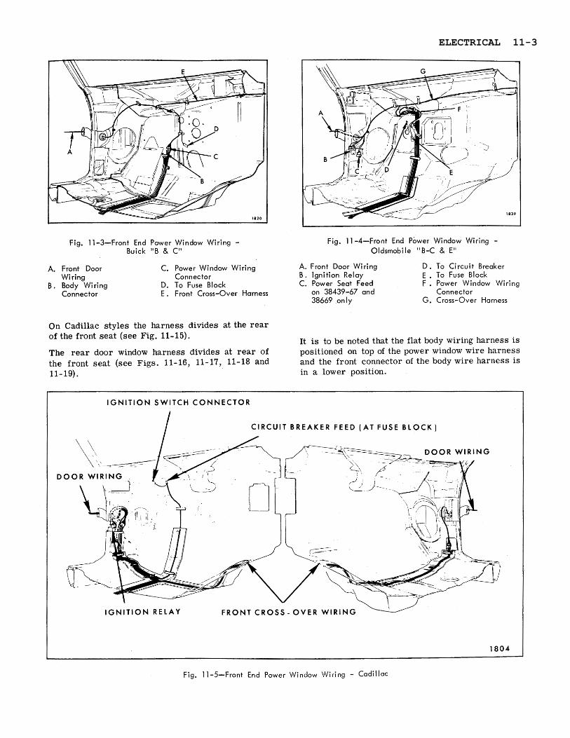
Fig. 11-3-Front End Power Window Wiring - Buick "B & C"
Fig. 11 -4-Front End Power Window Wiring - Oldsmobile "8-C & E"
A. Front Door Wiring
B. Body Wiring Connector
C. Power Window Wir ing A. Front Door Wiring D. To Circuit Breaker Connector B. Ignition Relay E . To Fuse Block
D. To Fuse Block C. Power Seat Feed F . Power Window Wiring E . Front Cross-Over Harness on 38439-67 and Connector
38669 only G. Cross-Over Harness
On Cadillac styles the harness divides at the r e a r of the front seat (see Fig. 11-15).
It is to be noted that the flat body wiring harness is The r ea r door window harness divides a t r e a r of positioned on top of the power window wire harness the front seat (see Figs. 11-16, 11-17, 11-18 and and the front connector of the body wire harness i s 11-19). in a lower position.
IGNITION SWITCH CONNECTOR
I CIRCUIT BREAKER FEED (AT FUSE BLOCK)
IGNITION RELAY FRONT CROSS - OVER WIRING
1808
Fig. 11-5-Front End Power Window Wiring - Cadillac
ELECTRICAL 11-3

LEFT FRONT DOOR
I 1472
Fig. 11-&Front End Power Window Wiring - All "A" Body Styles
I I I CONNECTOR FOR LEFT AND RIGHT I ( QUARTER W I N D O W WIRING SWITCH BLOCK MASTER SWITCH BLOCK I
1 1805
Fig. 11-7-Left Side Power Window Wiring - 67 "B & C" Styles
11-4 ELECTRICAL

Fig. 11-8-Rear Quarter Power Window Wiring - "B & C" 37 Styles
Fig. 1 1-9-Rear Quarter Power Window Wiring - "0-1 1 " Style
Quarter window' Harness on Cadillac se r ies and under the r e a r seat cushion on "07-17 and 37)) styles. On Cadillac, "57 and
The left and right round wire harness connects to 67" styles the round wire harness connects to the the main flat feed harness behind the r ea r quarter flat wire at the forward end of the rea r quarter a r m rest foundation on convertible styles except a r m rest assembly.
QUARTER WINDOW CONTROL SWITCH BLOCK DOOR WINDOW MASTER CONTROL SWITCH BLOCK
QUARTER WINDOW MOTOR
IN LINE MOTOR WIRE HARNESS CONNECT
Fig. 11-10-Left Side Power Window Wiring - "A" 67 Styles
ELECTRICAL 11-5

Rear Door Window Harness
Fig. 11-1 1-Rear Quarter Window Wiring - "A" Coupe
Less 67 Styles
I
The left and right rea r door harness connects to the main flat feed harness in the base of the center pillar. To disengage the connector, pull harness inboard at base of center pillar for accessibility.
Power windows a re operated by a rectangular shaped 1 2 volt series-wound motor with an internal circuit breaker and a self-locking rubber coupled gear drive. The harness to the door window motor connector is designed with a locking embossment to insure a positive connection. When disengaging the harness connector from the door motor, i t is necessary to depress the thumb release. When in- stalling the harness, the thumb release must be held depressed until the embossment on the female connector is locked in the hole of the motor connector.
Some r ea r quarter window motors and ventilator motors a r e designed with a locking type connector which should not be disengaged. When testing o r removing the motor, the in-line connector located inboard of the inner panel should be disengaged.
Fig. 11-12-Left Side Power Window Wiring - Oldsmobile "E" Optional
1. Flat to Round Wire Connector
2. Quarter Window Switch Block
3. Optional Door Courtesy Lamp
4. Door Window Motor
5. Master Control Switch Block 6. Door Courtesy Lamp Connector 7. Quarter Window Motor
11-6 ELECTRICAL

Fig. 11-13-Right Side Power Window Wiring - Oldsmobile "E" - Standard
1. Door Window Switch Block 2. Door Window Motor
3. Quarter Window Switch Block 4. Quarter Window Motor
5. Flat to Round Wire Connector
Tests a r e made at this location on those styles. The power window circuit is protected by a circuit breaker. Refer to electrical introduction for spe- cific locations.
Relay
Oldsmobile and Cadillac styles only - In addition to the circuit breaker, a relay is used in the cir - cuit. The relay prevents the operation of the power windows until the ignition switch is turned '(on".
Cut-Out Switch
A cut-out switch (Cadillac styles only) installed on the left front door a r m rest , is designed to tempo- rarily by-pass the relay circuit so the windows may be operated only from the master control switch when the ignition is in the off position. Fig. 11-14-Rear Quarter Power Wiring - Buick "E"
CONNECTOR
QUARTER W I N D O W WIRING CONNECTOR
ELECTRICAL 11-7

I CUT - OUT S A F E T Y 1
Fig. l l-15-Left Side Power Window Wiring - Cadillac "57" Styles
To perform this operation, the cut-out switch con- t ro l button is held in the "EMERG" position while the master control switch buttons a r e actuated. When the cut-out button is released, the button will return to the "NORMAL" position.
The cut-out switch button should be set in the "LOCK" position when ignition switch is "ON') to permit normal operation of power windows from al l switch locations. If the control button is left in the "NORMAL" position with the ignition switch on, the windows will operate only from the master control switch.
Power Window Circuit Checking Procedures
Failures in a circuit a r e usually caused by short circuits o r open circuits. Open circuits a r e usually caused by breaks in the wiring, faulty connection o r mechanical failure in a component such a s a switch o r circuit breaker. Short circuits a r e usually caused by wires from different components of the circuit contacting one another o r by a wire o r component grounding to the metal of the body due to a screw through the wire, insulation cut through by sharp metal edge, etc.
Fig. Il-16-Left Rear Door Power Window Wiring - "Au-39 Styles
11-8 ELECTRICAL

Fig. 11-17-Right Side Power Window Wiring "A" 35-55-65 and 69 Styles
It may be necessary to use only one o r all of the procedures outlined to locate an electrical failure in the circuit. If the location of the failure is evi- dent follow only the steps required to check the affected wire o r component. If the location of the failure is not evident, follow the procedure a s out- lined. Be su r e to check the harness connectors for proper engagement and become familiar with the typical circuit diagrams. (See Figs. 11 - 23 through
,2f- 30).
Circuit diagram of 4 door styles is shown but basic circuitry and color <ode is similar on two door styles.
a. Checking Feed Circuit Continuity at Circuit Breaker
1. Connect one test light lead to battery side of circuit breaker and ground other lead. If tester does not light, there is an open o r short cir- cuit in feed circuit to breaker.
2. To check circuit breaker, disconnect the output feed wire (the wire opposite the power source feed to the breaker) from the breaker and with test light, check terminal from which wire was disconnected. If tester does not light, circuit breaker is inoperative.
ELECTRICAL 11-9

Fig. 1 1-18-Left Side Power Window Wiring - "B & C" Four Door Styles
1. Switch Block 2. Master Switch
Block
b. Checking Relay Assembly at Shroud- Oldsmobile and Cadillac Only
3. Front Door Motor 4. Rear Door Window Wire
Harness Connector 5. Rear Door Motor
NOTE: Current should be present whether ignition is ('on" o r "off".
3 . With ignition switch on, connect one test light 1. With tes t light, check relay feed. If tes ter does lead to the master window control switch feed not light, there is an open o r short circuit terminal (red-white stripe) of the switch block between relay and circuit breaker. and ground other test lead.
2. Turn ignition switch on and with test light 4. If tes ter does not light, there is an open o r check output terminal of relay. If tes ter does short circuit between the relay and cut-out not light, the relay is inoperative' o r there is
switch. a short o r open circuit between ignition switch and relay assembly. (Check fuse at dashpanel).
d. Checking Cut-Out Switch-Cadillac Only
c. Checking for Current at Cut-Out Switch- Cadillac Only
1. Connect one test light lead to relay by-pass (over ride) terminal (orange-black stripe) of the switch block and ground other test lead.
2. If tes ter does not light, there is an open o r short circuit between by-pass feed source and cutout switch.
With ignition switch off, connect one end of a #12 gauge jumper wire to by-pass feed ter- minal (over-ride) (orange-black stripe) and the other end to the center terminal (master control switch feed - red-white stripe).
Operate master control switch. If windows operate with jumper wire but not with the cut- out switch, the by-pass side of the switch is defective.
11-10 ELECTRICAL

r M A S T E R SWITCH B L O C K I
REAR D
Fig. 11-19-Left Side Power Window Wiring - Cadillac "39-69" Styles
3 . With the ignition switch on, connect one end of e. Checking Feed Circuit Continuity a #12 gauge jumper wire to center terminal at Window Control Switch (master control switch feed - red-white stripe) and the other end in the right and left r e a r quarter o r door and right front door feed ter- 1. Connect one test light lead to feed terminal of minal (pink-black stripe). switch block and ground other tes ter lead to
body metal (see Fig. 11-20). 4. Operate control switches. If any of the windows
operate with the jumper but not with the cut- 2. If tes ter does not light, there is an open o r out switch, the switch is defective. short circuit between switch and power source.
Fig. 1 1 -20-Checking Feed Circuit Fig. 1 1 -21-Checking Window Control Switch
ELECTRICAL 11-11

g. Checking Wires Between Door Window Switch and Door Window Motor
Fig. 1 l-22-Checking Circuit Between Switch and Motor
f. Checking Window Control Switch
1. Insert one end of a #12 gauge jumper wire to the switch feed terminal and the other end to one of the motor lead terminals in the switch block. Repeat this check on the remaining nlotor lead terminal (see Fig. 11-21).
2. If the window operates with the jumper wire, but does not operate with the switch, the switch is defective.
1. Disengage harness connector from window motor connector. The thumb release on the harness connector must be depressed before it can be disengaged from the motor.
2. Insert one end of a #12 gauge jumper wire to the switch feed terminal and the other end to one of the nlotor lead terminals in the switch block (see Figure 11-21).
3 . With test light check for current at terminal being tested. If tes ter does not light, there i s an open o r short circuit in the harness be- tween the coiltrol switch and motor connector (see Fig. 11-22).
4. Check other terminal.
h. Checking Wires Between Quarter Window Switch and Quarter Window Motor
1. Disengage the in-line connector located in- board of the quarter inner panel a s required.
2. Insert one end of a #12 gauge jumper wire in the switch feed terminal and the other end in one of the motor lead terminals of the switch block (see Fig. 11-22).
COLOR CODE
RT FRONT DOOR I T REAR DOOR WINDOW SWITCH WINDOW SWITCH
TO CIRCUIT BREAKER
* I4
LT REAR DOOR WINDOW SWITCH
LT REAR DOOR WINDOW MOTOR
Fig. 1 l-23-Power Window Circuit Diagram - ~ h e v r o l e t - ~ o n t i a c - ~ u i c k "B & C"
11-12 ELECTRICAL
COLOR CODE
W I N D O W MOTOR
17 FRONT DOOR RT REAR DOOR W I N D O W SWITCH W I N D O W SWITCH
1813
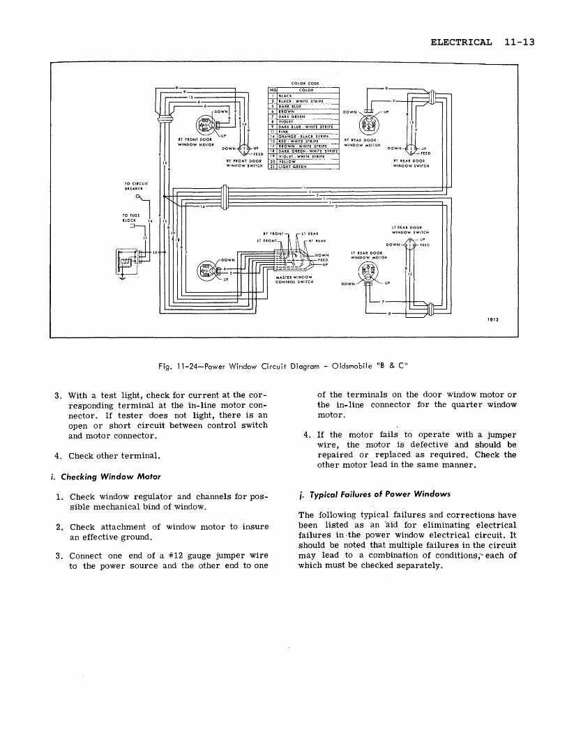
Fig. 11-24-Power Window Circuit Diagram - Oldsmobile "B & C"
3 . With a test light, check for current at the cor- of the terminals on the door window motor o r responding terminal a t the in-line motor con- the in-line connector for the quarter window nector. If tes ter does not light, there is an motor. open o r short circuit between control switch and motor connector. 4. If the motor fails to operate with a jumper
wire, the motor is defective and should be 4. Check other terminal. repaired o r replaced a s required. Check the
other motor lead in the same manner. i. Checking Window Motor
1. Check window regulator and channels for pos- i. Typical Failures of Power Windows
sible mechanical bind of window. The following typical failures and corrections have
2. Check attachment of window motor to insure been listed a s an 'aid for eliminating electrical an effective ground. failures in . the power window electrical circuit. It
should be noted that multiple failures in the circuit 3 . Connect one end of a #12 gauge jumper wire may lead to a combination of conditions; each of
to the power source and the other end to one which must be checked separately.
ELECTRICAL 11-13

CONDITION
1. None of the windows will op- erate with ignition switch on.
2. Right r e a r door window does not operate from master con- trol switch on left door o r from control switches on right rea r door. Left door window operates.
3 . Right door windows will op- erate from left door master control switch but will not op- erate from right door control switches. Left door windows operate.
CAUSE
Short o r open circuit in power feed circuit.
A. Short o r open circuit between right rea r door harness and power window front harness.
B. Short o r open circuit in af- fected window control switch o r window motor circuit.
C. Possible mechanical failure o r bind in window channels.
D. Defective window motor.
Open o r short circuit in front harness feed wire circuit.
CORRECTION
A . C h e c k c i r c u i t b r e a k e r operation.
B. Check relay operation at left cowl.
C. Check f e e d connection t 0
power harness beneath instru- ment panel.
D. Check the feed circuit wires for possible s h o r t o r open circuit.
E. Check cut-out switch.
A. Check harness ~ ~ n n e c t o r s be- neath outer ends of instrument panel for proper installation.
B. Check wires in power window front harness f o r possible short o r open circuit.
C. Check operation of rea r door window control switch.
D. Check circuit from window control s w i t c h to window m o t o r f o r short o r open circuit.
E. Check window regulator and channels f o r possible me- chanical failure o r bind.
F. Check operation of motor.
Follow up feed wire in front har- ness for possible short o r open circuit.
T
11-14 ELECTRICAL

1
RT
FT
DO
OR
R
T FT
D
OO
R W
IND
OW
R
T RR
D
OO
R W
IND
OW
R
T RR
D
OO
R
WIN
DO
W M
OT
OR
S
WIT
CH
CO
NN
EC
TO
R
SW
ITC
H C
ON
NE
CT
OR
W
IND
OW
MO
TO
R
CL
OS
E
$II
FE
ED
O
PE
N
OP
EN
C
LOS
E
CL
OS
E
16
c- 18=
f
OP
EN
CO
LO
R
CO
DE
I 16
1 J1
I J
FU
SE
BL
OC
K
r---1
1,
3 I
I,
17
7 1
8
16
16
14
4
PO
WE
R S
EA
T F
EE
D
8.
8
CLO
SE
tT
FT
DO
OR
RT
6 L
T RR
D
OO
R 6
RT
FT
D
OO
R C
ON
TR
OL
W
IND
OW
MO
TO
R
- OP
EN
:$
SW
ITC
H C
ON
NE
CT
OR
FE
ED
LT
FT
DO
OR
MA
ST
ER
CO
NT
RO
L
----
--
SW
ITC
H C
ON
NE
CT
OR
FE
ED
LT
RR
D
OO
R W
IND
OW
OP
EN
LT
RR
DO
OR
IGN
ITIO
N R
ELA
Y
SW
ITC
H C
ON
NE
CT
OR
W
IND
OW
MO
TO
R
OV
ER
RID
E F
EE
D
IGN
ITIO
N R
ELA
Y
CO
NN
EC
TO
R
MA
ST
ER
WIN
DO
W
11
CLO
SE
C
ON
TR
OL
SW
ITC
H
1814
ELECTRICAL 11-15

+
R F DOOR RT FRONT DOOR W I N D O W d R l F l DOOR
VENT M O ~ O R VENT S W ~ T C H CONNICTOR WINDOW MOTOR
WARNING LAMP
R l W I N D O W CLOSE
R l W i N D O W OPEN
I T F l DOOR IAMB SWITCH
COURTESY LAMP CONNECTOR
FT DOOR IAMB S k l T C H INSTR PANEL COURTESY 6 HORllONTAL SEA1 MOTOR
~l DOOR WARNING LAMP GROUND
RIGHT STOP 6 DIRECTIONAL LAMP FE
11 STOP 6 DIRECTIONAL LAMP FEED
FUEL GAUGE SENDING UNIT
TAIL 6 LICENSE LAMP P
REAR RADIO SPEAKER FEED
FUSE BLOCK FURNISHED6 INSTALLED BY CADILLAC
L l FT DOOR WARNING LAMP
I T 611 REAR DOOR VENT 11 FT DOOR
RT 6 1 1 RR DR 6FT DR WINDOW 6 VENT SWITCH CONNECTOR PEED
LT F l DOOR MASTER WINDOW 6 VENT CONTROL s w l i c n CONNE
IGNITION RELAY OVERRIDE FEED
LEFT FRONT DOOR MASTER WINDOW
CONTROL SWITCH CONNECTOR
Fig. 1 1 -26-Standard Body and Power Wiring Circuit Diagram - Cadillac 68169
11-16 ELECTRICAL

ELECTRICAL 11-17

RT.
R
EA
R
QU
AR
TE
R
RT.
FR
ON
T
DO
OR
W
IND
OW
MO
TO
R
WIN
DO
W
MO
TO
R
RT.
FR
ON
T D
OO
R
RT.
R
EA
R
QU
AR
TE
R
WIN
DO
W
SW
ITC
H
LT.
RE
AR
Q
UA
RT
ER
W
IND
OW
S
WIT
CH
LT.
RE
AR
Q
UA
RT
ER
W
IND
OW
M
OT
OR
MA
STE
R W
IND
OW
C
ON
TR
OL
SW
ITC
H
LT.
FR
ON
T
DO
OR
W
IND
OW
M
OT
OR
11-18 ELECTRICAL

Fig. 11-28-Power Window Circuit Diagram - Oidsrnobile "A"
ELECTRICAL 11-19
TO RIGHT DOOR COURTESY 6 WARNING LAMP JUMPER
RIGHT QUATER WINDOW MOTOR
COLOR CODE
TO DIVISION HARNESS OR SEAT BACK JUMPER
RELAY DOWN
;:11
WINDOW MOTOR LEFT QUARTER WINDOW MOTOR
TO LEFT DOOR COURTESY 6 WARNING LAMP JUMPER 2187
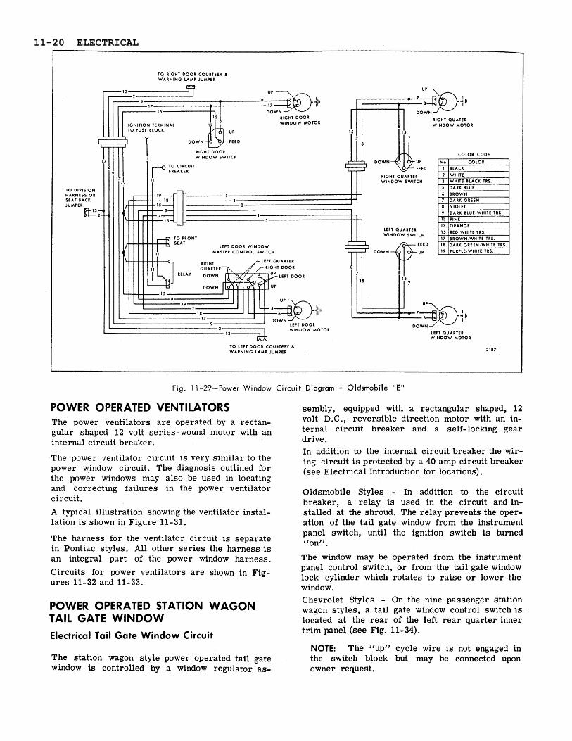
Fig. 1 1 -29-Power Window Circuit Diagram - Oldsmobile "E"
POWER OPERATED VENTILATORS sembly, equipped with a rectangular shaped, 12
The power ventilators a r e operated by a rectan- gular shaped 12 volt series-wound motor with an internal circuit breaker.
The power ventilator circuit is very siinilar to the power window circuit. The diagnosis outlined for the power windows may also be used in locating and correcting failures in the power ventilator circuit. A typical illustration showing the ventilator instal- lation is shown in Figure 11-31.
The harness for the ventilator circuit is separate in Pontiac styles. All other se r ies the harness is an integral part of the power window harness.
Circuits for power ventilators a r e shown in Fig- u res 11-32 and 11-33.
volt D.C., reversible direction motor with an in- ternal circuit breaker and a self-locking gear drive. In addition to the internal circuit breaker the wir- ing circuit i s protected by a 40 amp circuit breaker (see Electrical Introduction for locations).
Oldsmobile Styles - In addition to the circuit breaker, a relay is used in the circuit and in- stalled at the shroud. The relay prevents the oper- ation of the tail gate window from the instrument panel switch, until the ignition switch is turned Uon"
The window may be operated from the instrument panel control switch, o r from the tail gate window lock cylinder which rotates to raise o r lower the window.
POWER OPERATED STATION WAGON Chevrolet Styles - On the nine passenger station wagon styles, a tail gate window control switch is
TAIL GATE WINDOW located a t the r e a r of the left r e a r quarter inner
Electrical Tail Gate Window Circuit t r im panel (see Fig. 11-34).
NOTE: The "up" cycle wire is not engaged in The station wagon style power operated tail gate the switch block but may be connected upon window is controlled by a window regulator as- owner request.
11-20 ELECTRICAL

RIGHT QUARTER
u P
WINDOW MOTOR
COLOR CODE
DOWN
LEFT QUARTER WINDOW MOTOR
LEFT DOOR WINDOW MOTOR 2175
- -- - -- - -
Fig. 11-30-Power Window Circuit Diagram - Buick "E"
To prevent the window from being operated to the On all "A & Bw Bodies - peee ta i l gate window up position when the tail gate has been lowered, a harness runs adjacent to the body wire and consists safety switch is located on the tail gate lock pillar. of two major sections. The front section of flat The safety switch opens the ground circuit of the wire extends from the left center of the toe pan tail gate window motor, making i t inoperative. See (Fig. 11-35 and 11-36), rearward and connects to tail gate views. the r e a r harness a t the right r e a r quarter a rea
(see Figs. 11-37, 11-38, 11-39). The r e a r cross bar wiring is shown in Figures 11-40, 11-41 and the tail gate wiring is shown in Figures 11-42, 11-43 and 11-44.
On Chevrolet ([X" Bodies - The tail gate window harness is a component par t of the body wiring harness which consists of two sections (front and rear ) see Figures 11-45, 1'1-46, 11-47 and 11-48.
Checking Procedure
Fig. 1 1-31 -Typical Power Ventilator Wiring
Before performing an intensive checking procedure to determine any failure of the circuit, check all the connectors for proper installation. The check- ing procedures below may be used to check the operation of a switch o r motor after the cause of the electrical failure has been isolated to a par- ticular par t of the circuit. Refer to the circuit diagrams. See Figures 11-49, 11-50 and 11-51.
ELECTRICAL 11-21

CO
LOR
C
OD
E
29
28
RIG
HT
DO
OR
C
V"
MO
TOR
q R
IGH
T D
OO
R
"CV
9* S
WIT
CH
TO P
OW
ER W
IND
OW
S
[ N
o.
I C
OLO
R
1
P 14
CIR
CU
IT B
REA
KER
I -
-
14
1 OR
AN
GE
- BLA
CK
ST
RIP
E
28
LEFT
D
OO
R
"CV
" M
OTO
R
21
MA
STER
"C
V"
SW
ITC
H
28
29
14
11-22 ELECTRICAL
RT.
FT.
DO
OR
RT
. FT
. D
OO
R W
IND
OW
R
T. F
T. D
OO
R
SW
ITC
H C
ON
NE
CTO
R
WlN
DO
W M
OT
OR
RT.
"C
V"
OP
EN
R
T.
"CV
" C
LOSE
RT.
W
lND
OW
C
LOSE
RT.
WlN
DO
W
OP
EN
CO
LOR
C
OD
E
TO
WA
RN
ING
LA
MP
RIG
HT
FRO
NT
DO
OR
JA
MB
SW
ITC
H
FUSE
BLO
CK
CO
NN
EC
TOR
TO
P
OW
ER
SEA
T H
AR
NE
SS
LEFT
FR
ON
T D
OO
R
JAM
B S
WIT
CH
TO
WA
RN
ING
LA
MP
IGN
ITIO
N R
ELA
Y O
VE
RR
IDE
FEE
D
LT.
FT.
DO
OR
MA
STE
R W
IND
OW
O
PE
N
AN
D V
ENT
CO
NTR
OL
SW
ITC
H
CO
NN
EC
TOR
FEE
D
RT.
AN
D L
T. R
EAR
DO
OR
OR
Q
TR.
AN
D R
T.
FT.
DO
OR
WIN
DO
W
AN
D
PO
WE
R W
IND
OW
LT
. FT
. D
OO
R
LT. n. D
OO
R
VE
NT
CO
NTR
OL
SW
ITC
H C
ON
NE
CTO
R
c-~
qu
~ S
WIT
CH
W
IND
OW
MO
TO
R
FEED
C
ON
NE
CTO
R
VE
NT
MA
STE
R C
ON
TRO
L V
EN
T M
OT
OR
S
WIT
CH
CO
NN
EC
TOR
LT
. RR
. C
LOSE
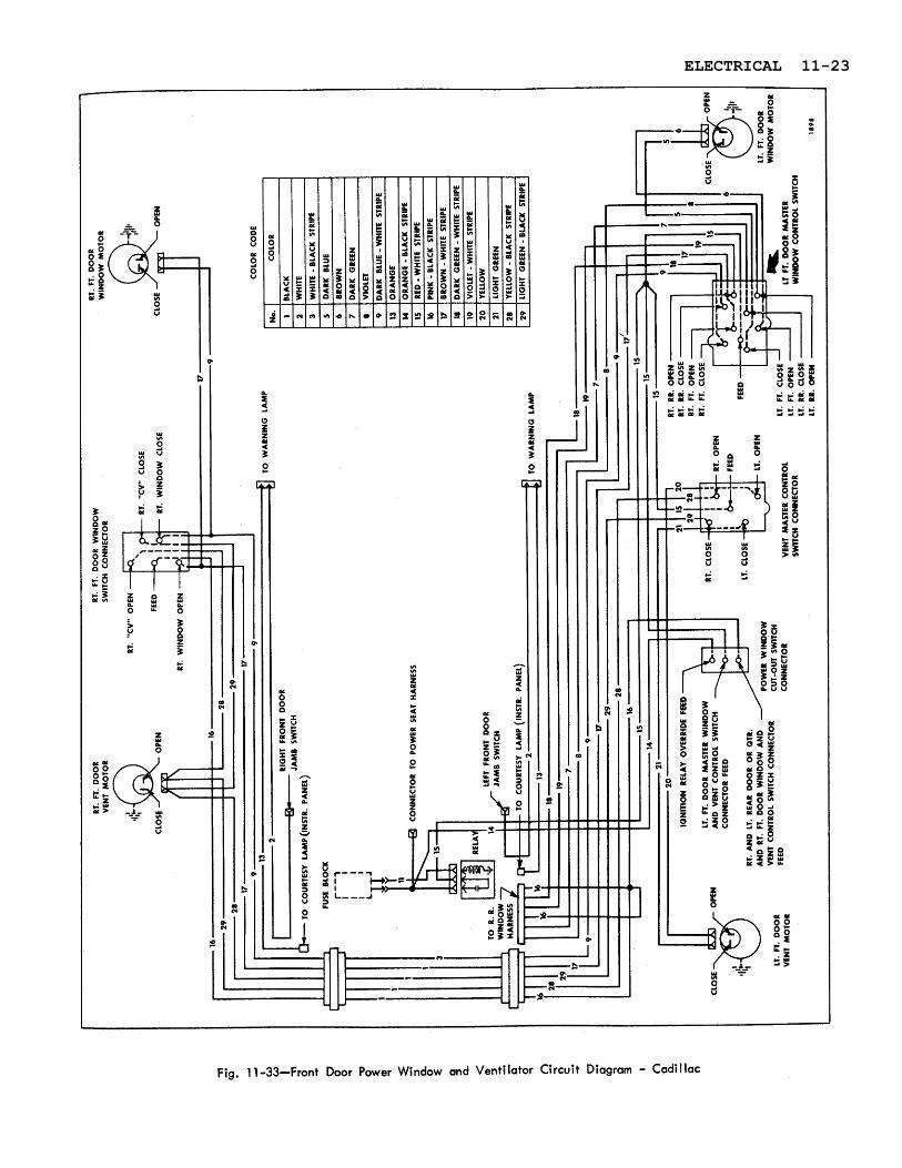
ELECTRICAL 11-23

REAR QUARTER COURTESY LAMP WIRING
GROUND BLACK
LAMP SWITCH GROUND WHITE-BLACK STRIPE
Fig. 11-34-Left Side Power Tail Gate Window and Body Wiring - Chevrolet, Pontiac "B" Bodies
a. Checking Feed Circuit Continuity at Circuit Breaker 2. To check circuit breaker disconnect the output feed wire (the wire opposite the power source
1. Connect one test light lead to battery side of feed to the breaker) from the breaker. Connect circuit breaker and ground other lead. If tester one test light lead to the output terminal and does not light, there is an open or short circuit ground other lead. If tester does not light, in feed circuit to breaker. circuit breaker is inoperative.
BODY WIRE
CONNECTOR
POWER TAIL GATE W I N D O W WIRE HARNESS CONNECTOR
Fig. i 1 -35-Front End Wiring - Chevrolet, Pontiac "B" Body Fig. 11-36-Front End Wiring - A l l "A" Bodies
11-24 ELECTRICAL
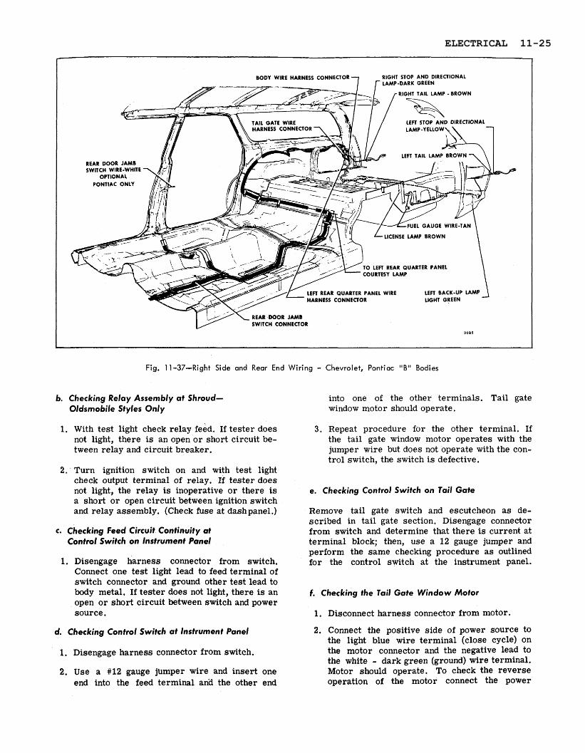
BODY WIRE HARNESS CONNECTOR RIGHT STOP A N D DIRECTIONAL LAMP-DARK GREEN
RIGHT TAIL LAMP - BROWN
REAR DOOR JAMB
EL GAUGE WIRE-TAN
LICENSE LAMP BROWN
TO LEFT REAR QUARTER PANEL COURTESY LAMP
LEFT REAR QUARTER PANEL WIRE LEFT BACK-UP LAMP HARNESS CONNECTOR
REAR DOOR JAMB SWITCH CONNECTOR
1 0 8 5
Fig. 11-37-Right Side and Rear End Wiring - Chevroiet, Pontiac "Bi' Bodies
b. Checking Relay Assembly at Shroud- Oldsmobile Styles Only
1. With test light check relay feed. If tester does not light, there is an open or short circuit be- tween relay and circuit breaker.
2. Turn ignition switch on and with test light check output terminal of relay. If tester does not light, the relay i s inoperative o r there is a short o r open circuit between ignition switch and relay assembly. (Check fuse at dashpanel.)
c. Checking Feed Circuit Continuity at Control Switch on lnstrument Panel
1. Disengage harness connector from switch. Connect one test light lead to feed terminal of switch connector and ground other test lead to body metal. If tester does not light, there is an open o r short circuit between switch and power source .
into one of the other terminals. Tail gate window motor should operate.
3 . Repeat procedure for the other terminal. If the tail gate window motor operates with the jumper wire but does not operate with the con- trol switch, the switch is defective.
e. Checking Control Switch on Tail Gate
Remove tail gate switch and escutcheon a s de- scribed in tail gate section. Disengage connector from switch and determine that there is current at terminal block; then, use a 12 gauge jumper and perform the same checking procedure a s outlined for the control switch at the instrument panel.
f. Checking the Tail Gate Window Motor
1. Disconnect harness connector from motor.
d. Checking Control Switch at Instrument Panel 2. Connect the positive side of power source to the light blue wire terminal (close cycle) on
1. Disengage harness connector from switch. the motor connector and the negative lead to the white - dark green (ground) wire terminal.
2. Use a #12 gauge jumper wire and insert one Motor should operate. To check the reverse end into the feed terminal anki the other end operation of the motor connect the power
ELECTRICAL 11-25

OME LIGHT HARN
STOP &DIRECTIONAL LAMP - DARK GREEN
RIGHT TAlL LAMP - BROWN
K - LIGHT GREEN
LEFT TAlL LAMP - BROWN
LEFT STOP & DIRECTIONAL LAMP - BLACK-YELLOW
BACK - UP LAMP BLACK - LIGHT GREEN
Fig. 11-38-Right Side and Rear End Wiring - Chevrolet, Pontiac, Oldsmobile "A" Bodies
DOME LIGHT AND BACK BODY OPENING HEADER COURTESY LAMP CONNECTORS
RT. TAIL LAMP - BROWN
RT. STOP L DIRECTIONAL LAMP - DARK GREEN
BACK BODY OPENING HEADER COURTESY LAMP
TAIL GATE WMDOW CONNECTOR
BACK -UP LAMPS
LT. TAlL LAMP - M O W N
LT. STOP h DIRECTIONAL
2117
Fig. 1 1 -39-Right Side and Rear Wiring - Buick "A" Body 55-65 style'
11-26 ELECTRICAL

TAIL GATE WlRE HARNESS
RIGHT BACK-UP LAMP
(25-26000 SERIES ONLY)
Fig. ll-40-Rear Cross Bar Wiring - Chevrolet, Pontiac "B" Bodies
source to the tan - white wire terminal (open cycle). If motor does not operate in both di- rections, repair o r replace motor.
g. checking Operation of Safety Switch
1. With tail gate open, depress switch a r m to simulate the tail gate being closed on all "A & B" Styles. For Chevrolet ('X" use jumper wire from open contact to body ground. Oper- ate control switch. If motor does not operate, either switch is defective o r the circuit is open from the motor to the switch.
2. To check for defective switch, connect one end of test light to a source of power and the other lead to the safety switch terminal. If the tes ter lights when the switch lever is actuated, the switch is operative.
* RIGHT BACK - U P 1- LAMP WlRE
ALL E X C E P T 3 3 , 0 0 0 S E R I E S 1484
Fig. ll-41-Rear Cross Bar Wiring - A l l "A" Bodies
L l f l 1111 LAMP AND STOP. DIIECIIONAL LAMP
Fig. l l -42-Tai l Gate Wiring - Chevrolet "B" Bodies
NOTE: Safety switch completes the ground circuit from the motor.
SAFETY SWITCH 1 SWITCH BLOCK 7 7 1
1 I
Fig. 11 -43-Tail Gate Wiring - Pontiac "B" Bodies
Fig. 1 l-44-Tail Gate Wiring - A l l "A" Bodies
ELECTRICAL 11-27

TAIL GATE ELECTRIC WINDOW SWITCH CONNECTOR
Fig. 11-45-Front End Wiring - Chevrolet "XI' Bodies
Fig. 11-47-Rear Cross Bar Wiring - Chevrolet "X" Bodies
Fig. 11-46-Left Side Wiring - Chevrolet "X" Bodies Fig. 11-48-Tail Gate Wiring - Chevrolet "Xu Bodies
11-28 ELECTRICAL

NO. COLOR
1 BLACK
3 WHITE-BLACK
13 ORANGE
14 ORANGE-BLACK
18 DARK GREEN-WHITE
22 TAN
24 LIGHT BLUE
25 TAN-WHITE
ELECTRICAL 11-29

TAlL GATE WINDOW SAFE1 Y SWITCH
I k m l ; l l
4
CONNECTOR TO CHASSIS WIRING
TAlL GATE WINDOW MOTOR
PONTIAC ONLY
COLOR CODE OPEN
FEED
CLOSE
TAlL GATE WINDOW CONTROL SWITCH BLOCK
2122
Fig. 1 1 -50-Power Tail Gate Window Circuit - All "A & B" 35-55 and 65 Styles
No. COLOR
1 BLACK
3 WHITE - BLACK TRS.
4 WHITE - DARK GREEN
14
24 25
ORANGE - BLACK TRS.
LIGHT BLUE
TAN - WHITE TRS.
11-30 ELECTRICAL

COLOR CODE RIGHT FRONT DOOR JAMB SWITCH RIGHT STOP & DIRECTIONAL LAMP
RIGHT TAlL LAMP
TAlL GATE WINDOW SAFETY SWITCH
BACK-UP LAMP
TAlL GATE WINDOW
TAlL GATE WINDOW TAIL GATE WINDOW CONTROL SWITCH
LICENSE LAMP
CIRCUIT BREAKER FEED -12
DOME LAMP FEED BACK-UP LAMP
DOME LAMP GRO
GAS GAUGE FEED LEFT TAlL LAMP
BACK-UP LAMP FEED
RIGHT STOP DIRECTION LEFT STOP a DIRECTIONAL LAMP
TAlL & LICENSE LAMP FEE REAR BODY
LEFT STOP & DIRECTIONA CONNECTOR
CONNECTOR TO CHASSIS WIRING - /
Fig. 11-51-Power Tail Gate Window Circuit - Chevrolet "Xu Bodies
h. Trouble Shooting
CORRECTION
1. Check affected wiring for open or short circuit and check con- nector at switch for proper installation.
2. Check operation of switch.
1. Check affected wiring for open o r short circuit.
2. Check operation of motor.
CONDITION
A. The tail gage window operates up and down from the tail gate switch but does not operate from the switch at the instru- ment panel.
B. With the tail gate closed, the window operates downward but does not operate upward when the switch at the instrument panel o r tail gate is actuated.
CAUSE
1. Open o r short circuit from power source to control switch at instrument panel.
2. Defective or inoperative con- trol switch.
1. Open or short circuit in up cycle feed wire.
2. Defe.ctive motor.
ELECTRICAL 11-31

HORIZONTAL SEATS Description
CORRECTION
1. Check operation of circuit breaker.
2. Check affected circuit for open or short circuit.
3 . Check connectors t o safety switch and motor for proper engagement.
4. Check t a i l g a t e mechanical parts for bind o r failure.
5. Check operation of motor.
CONDITION
C. The window will not operate up or down from any of the control switches.
The seat adjusters for the bench-type and bucket- type seat a r e actuated by a 12 volt series-wound motor located near the front left side of the seat bottom frame, and are energized through a control switch installed in the seat side panel or in the door a rm rest. For typical wiring installations see Figure 11-52 for bucket-type seats and Figure 11 - 53 for bench-type seats.
CAUSE
1. Open or short circuit in cir- cuit from power source t o switches or motor.
2. Safety switch not connected or poor ground.
3 . Mechanical bind o r failure in t a i l gate window regulator mechanism.
4. Defective t a i 1 gate window regulator motor.
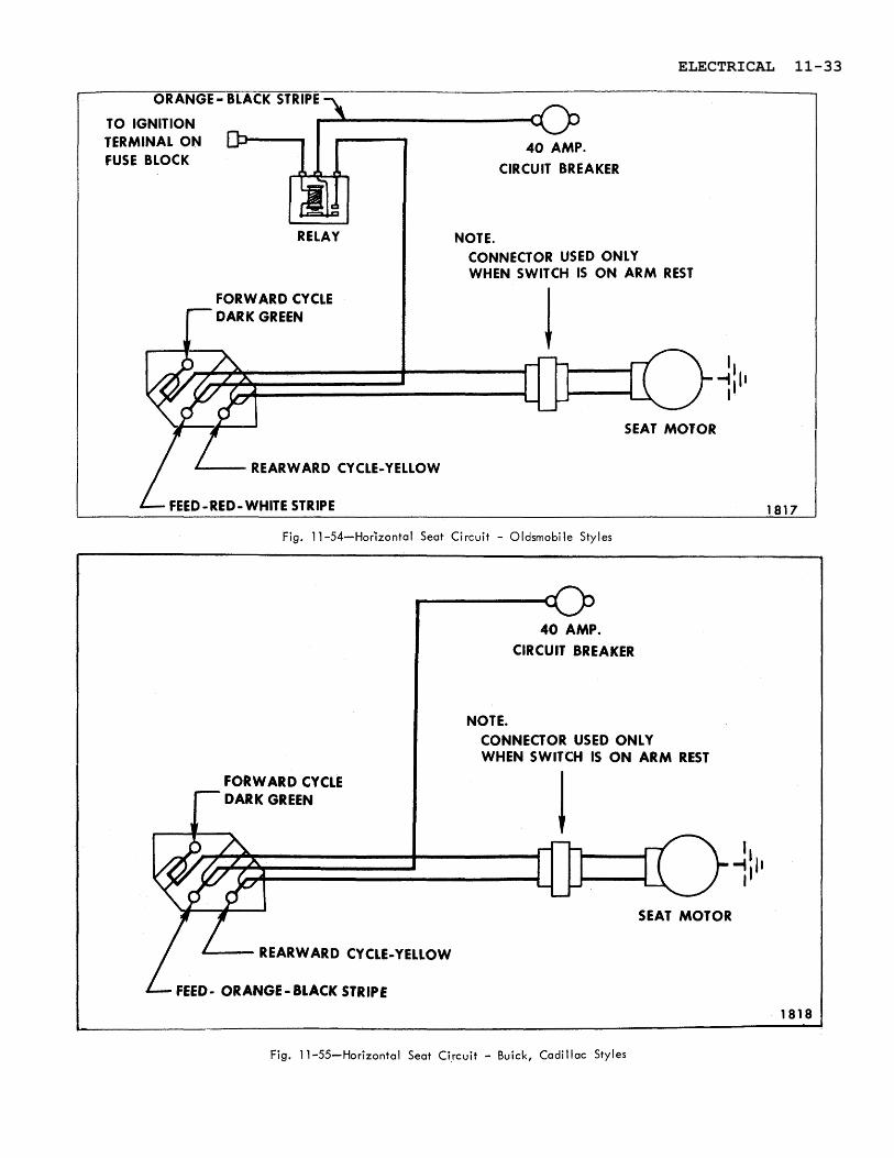
For circuit diagrams see Figures 11-54 and 11-55.
The horizontal seat circuit is protected by a cir- cuit breaker (refer to Electrical Introduction for specific location).
Oldsmobile styles only - In addition to the circuit breaker a relay is used in the circuit which pre- vents the operation of the seat until the ignition switch is turned "on".
The trouble diagnosis chart will help locate typical problems which may occur.
Fig. 1 1 -53-Horizontal Bench Seat Wiring
1. Front Seat Back 5. Motor Fig. 1 1 -52-Horizontal Bucket Seat Wiring Switch Feed - White 6. Ground Wire
2. Front Seat Back 7. Front Seat Back 1. Control Switch 4. Motor Switch Ground - Black Courtesy Lamp Feed 2. Feed Harness Connector 5. Control Cable 3. Control Switch Connector (Cadi l lac Only) 3. Feed Wire to Passenger Seat 6. Ground Wire 4. Harness. Feed Connector 8. Horizontal Control Cable
11-32 ELECTRICAL
TO IGNITION TERMINAL ON
CIRCUIT BREAKER
CONNECTOR USED ONLY WHEN SWITCH IS O N ARM REST
FORWARD CYCLE
SEAT MOTOR
REARWARD CY CLE-Y ELLOW
Fig, 11 -54-Horizontal Seat Circuit - Oldsmobi le Styles
t
L
40 AMP. CIRCUIT BREAKER
NOTE. CONNECTOR USED ONLY WHEN SWITCH IS O N ARM REST
FORWARD CYCLE
'I Ill'
w I
SEAT MOTOR
REARWARD CY CLE-YELLOW
FEED - ORANGE - BLACK STRIPE
1818 *
Fig. 11-55-Horizontal Seat Circuit - Buick, Cadillac Styles
ELECTRICAL 11-33

Typical Failures and Corrections of Horizontal Seat Circuit
CORRECTION
a. Connect one test light lead to ., feed terminal of switch block
and ground other tester lead to body metal. If tester does not light, there is an open or short circuit between switch and power source.
b. Check operation of seat con- trol switch with jumper wire. See "Checking Door Window C o n t r o l " f o r s i m i l a r operation.
c. Check circuit from control switch to motor for short or open circuit and check ground wire attachment at adjuster.
d. Check operation of motor with #12 gauge jumper wire. Con- nect one end of jumper wire to power source and the other end to one of the seat motor terminals. M o t o r should operate.
Perform same check at the other motor terminal. If motor does not operate, repair o r replace motor a s required.
a. Check operation of seat con- trol switch with jumper wire.
b. Check circuit from control switch to motor for short or open circuit.
c. Check operation of motor with #12 gauge jumper wire, Con- nect one end of jumper wire to power source and the other end to one of the seat motor terminals. Motor should op- erate. Psrform same check at the other motor terminal. If motor does not operate, re- pair or replace m o t 0 r a s required,
CONDITION
The seat motor does not operate in either the forward or rearward direction.
The seat motor operates in only one direction.
.
CAUSE
a. Open or short circuit in feed harness.
b. Inoperative motor.
a. Defective switch.
b. Open or short circuit in motor feed wires.
c . Defective seat motor.
11-34 ELECTRICAL

FOUR-WAY TILT SEAT
Description
The seat adjusters for the bench type and bucket type seats a r e actuated by a 12 volt, reversible, shunt- wound motor with a built-in circuit breaker. See Figures 11-56 and 11-57 for the bench seat installation and Figure 11-58 for the bucket seat installation.
The seat motor is energized by a toggle-type con- t rol switch installed in the left seat side panel. On 48467 style, the control switch is installed in the left front door a r m rest.
The four way seat circuit is protected by a circuit breaker (refer to Electrical Introduction for spe- cific location).
Oldsmobile styles only - In addition to the circuit breaker a relay is used in the circuit which pre- vents the operation of the seat until the ignition switch is turned "on".
The seat adjuster operating mechanism incorpo- ra tes a transmission assembly which includes two solenoids and four drive cables on bench type seats and two drive cables on bucket seats, leading to the seat adjusters. One solenoid controls the r e a r
Fig. 1 1 -56-Four-Way Bench Seat Wiring - " B & C" Body Styles
1. Vertical Control 6. Harness Feed Connector Cable (Yellow) 7. Rubber Coupler
2. Ground Wire 8. Transmission Assembly 3. Control Switch 9. Transmission End 4. Motor Plates 5. Motor Control 10. Horizontal Control
Relay Cable (Black)
Fig. 11-57-Four-Way Bench Seat Wiring - "A" -Body Styles
1. Control Switch Block 6, Vertical Drive Cable 2. Motor Control Relay (Ye1 low) 3. Motor 7. Horizontal Drive Cable 4. Rubber Coupler (B l ac k) 5. Harness Feed 8. Transmission Assembly
Connector 9. Seat Ground Wire
Fig. 11-58-Four-Way "Strato" Bucket Seat Wiring - A l l Styles
1. Control Switch 7. Transmission and 2. Motor Control Relay Solenoid Assembly 3. Motor 8. Vertical Control Cable 4. Harness Feed (Orange)
Connector 9. Horizontal Control Cable 5. Feed to Passenger Seat (B lack) 6. Pulley Cover Plate 10. Ground Wire
ELECTRICAL 11-35

vertical movement of the seat while the other sole- noid controls the horizontal movement of the seat. When the control switch is actuated, the motor and one of the solenoids are energized simultaneously. Then the solenoid plunger causes the shaft dog to engage with the large gear dog. Power is then transmitted through the transmission shaft on bench seats and through the pulleys on bucket seats, which in turn drives the actuator cables. When the ad- justers reach their limit of travel, the drive cables stop their rotating action and torque is absorbed by the rubber coupler connecting the motor and transmission on bench seats. On bucket seats torque is absorbed through the belt on the pulley. When the control switch lever is released the switch contacts open, a spring returns the shaft dog and solenoid plunger to their original position disengaging the shaft dog from the large gear dog. See ((Seat Section)) for exploded view of transmission.
Checking Procedure
It may be necessary to use only one or all of the procedures outlined to locate an electrical failure in the circuit. If the location of the failure is evi- dent follow only the steps required to check the affected wire o r component. If the location of the
failure is not evident, follow the procedures as outlined. Before performing any extensive check procedures, check the seat adjuster drive cables for proper attachment. In addition, study the seat circuit diagrams to become familiar with the seat circuit. (See Figs. 11-59 and 11-60).
a. Checking for Current at Circuit Breaker
1. Connect one test light lead to battery side of circuit breaker. If tester does not light, there is no current at battery side of circuit breaker,
2. To check circuit breaker, disconnect switch feed wire from breaker, and with a test light check for current at switch side of circuit breaker. If tester does not light, there is no current flowing through circuit breaker.
b. Checking the Ignition Relay Assembly- Oldsmobile " 0 & E" Styles Only
1. With test light check for current at circuit breaker side of relay. If tester does not light, there is a short o r open circuit between cir- cuit breaker and relay assembly.
2. Turn ignition switch on and with a test light check for current at output side of relay. If
Fig. 1 l-59-Four-Way Seat Circuit - All Styles except Oldsmobile "B & E" Styles
WIRE IDENTlFlCATiON
P 8 DOWN SOLENOID No. COLOR FUNCTION 7 DARK GREEN FIELD FEED-FORWARD & DOWN CYCLE
14 ORANGE - BLACK FEED TO RELAY
20 YELLOW FIELD FEED-REARWARD &UP CYCLE
21 LIGHT GREEN SOLENOID-VERTICAL MOVEMENT
24 LIGHT BLUE SOLENOID-HORIZONT AL MOVEMENT
I
FORWARD 8 DOWN CYCLE
CONNECTOR USED ON BUCKET SEATS ONLY
8 NOIDS
MOTOR LEADS
1493
11-36 ELECTRICAL

RD & UP CYCLE
FORE AFT SOLENOID
FORWARD & DOWN CYCLE
ARMATURE FEED - RED
FUSE BLOCK
TRANSMISSION 8 CONTROL SOLENO
RELAY
MOTOR LEADS
IDS
Fig. I 1 -60-Four-Way Seat Circuit - Oldsmobi le "B&E1' Styles
tes ter does not light, the relay is defective o r d. Checking for Current at Seat Control Switch there is a short o r open circuit between igni- tion switch and relay assembly. Check wires 1. Connect one test light lead to feed terminal of before replacing relay. switch block and ground other test light lead
to body metal.
NOTE: Oldsmobile '9 & E" Styles Only - 2. If tester does not light, there is no current at Ignition switch must be on for performing the
remainder of checking procedure. switch block. Failure is caused by an open o r short circuit between switch block and power source.
c. Checking Feed Circuit Continuity at Relay on Seat Motor-All Styles
1. Disengage three-way connector body from the seat motor relay.
2. Insert one test light lead into the relay power feed connector slot on the harness, and ground other tester lead.
3. If tes ter does not light, there is no current a t end of feed wire. Failure is caused by an open o r short circuit in feed circuit.
e. Checking the Seat Control Switch
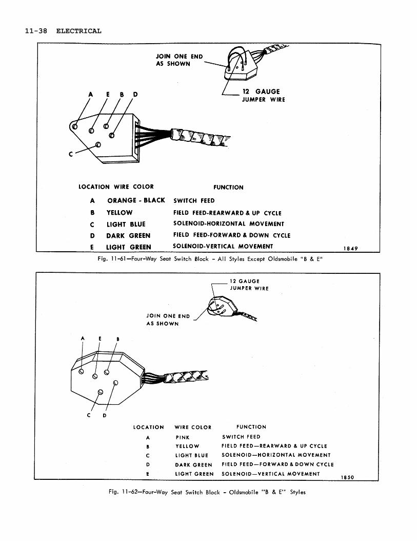
In the following operations which specify the seat control switch to be actuated, a switch that has been checked for proper operation may be connected to the switch block. If a switch is not available, a three-way jumper wire can be made to perform the switch function. The method of making the jumper wire and the switch locations to -be connected to obtain a specific movement of the seat a r e shown in Figures 11-61 and 11-62. If a jumper wire i s used, number the locations on the switch block a s indi- cated in the illustration.
ELECTRICAL 11-37
JOlN ONE END
A E B D JUMPER WlRE
LOCATION WIRE COLOR FUNCTION
A ORANGE - BLACK SWITCH FEED
B YELLOW FIELD FEED-REARWARD & UP CYCLE
C LIGHT BLUE SOLENOID-HORIZONTAL MOVEMENT
D DARK GREEN FIELD FEED-FORWARD & DOWN CYCLE
Fig. 1 1 -61-Four-Way Seat Switch Block - A l l Styles Except Oldsmobile " B & E"
12 GAUGE JUMPER WIRE
JOlN ONE END
AS SHOWN
C D
LOCATION WIRE COLOR FUNCTION
A PINK SWITCH FEED
B YELLOW FIELD FEED-REARWARD & UP CYCLE
C LIGHT BLUE SOLENOID-HORIZONTAL MOVEMENT
D DARK GREEN FIELD FEED-FORWARD & DOWN CYCLE
E LIGHT GREEN SOLENOID-VERTICAL MOVEMENT 1850
Fig. 1 1-62-Four-Way Seat Switch Block - Oldsmobile "B & E" Styles
11-38 ELECTRICAL

NOTE: To make jumper wire, obtain two pieces of #12 gauge wire, each 4 1/2" long. Join one end of each wire a s shown in diagram. The joined end can be inserted in the feed location in the switch block; one of the remaining ends can be inserted into one of the solenoid locations.
1. Obtain switch o r jumper wire and connect to switch block.
2. Operate switch i f used. If adjusters operate with switch o r jumper wire, but did not oper- ate with original switch, the original switch is defective or connector block was not suffi- ciently engaged.
IMPORTANT: To obtain a seat movement us- ing a three-way jumper wire at the switch block, the switch feed location, one of the motor field wire locations and one of the solenoid locations have to be connected simultaneously.
The switch locations to be connected to obtain a specific seat movement a re outlined a s follows:
(a) To raise seat, place jumper wire in loca- tions A, B and E.
(b) To lower seat, place jumper wire in loca- tions A, D and E.
(c) To operate seat forward, place jumper wire in locations A, C and D.
(d) To operate seat rearward, place jumper wire in locations A, B and C.
f. Checking Wires Between Control Switch and Motor Relay
1. Disengage three-wire harness connector from relay at motor.
2. Insert one test light lead into the motor field connector slot on harness and ground other lead.
3. Actuate seat switch to energize field wire being tested.
4. If tester does not light, there is no current at end of wire. Failure is caused by an open o r short circuit between end of wire and switch. Check other motor field wire in the same manner .
g. Checking the Relay Assembly
1. Disconnect three leads from relay assembly. These are the wires leading from the motor to the relay.
2. Connect one end of a jumper wire to one of the motor field feed studs on the relay and ground the other end of the jumper wire.
3. Connect one test light lead to motor armature feed stud on relay and groud other tester lead.
4. With jumper wire, energize the field stud which is not grounded.
CAUTION: Do not energize grounded side. If tester does not light, the relay is defective.
h. Checking the Motor Assembly
1. Disconnect motor field feed wires from motor.
2. Connect one end of a #12 gauge jumper wire to battery positive pole and other end to one of the motor field and the armature wires.
3. If motor does not operate, motor is defective. Check the remaining motor field wire in the same manner.
i. Checking Wires Between Switch and Solenoids
1. Disconnect harness connector from transmis- sion assembly.
2. Connect one test light lead to one terminal of power feed and ground other test light lead to body metal.
3. Operate switch to wire being tested. If tester does not light, there is no current at the end of harness wire. Failure is caused by an open or short circuit between end of wire and switch or defective switch.
4. Check other wire in same manner.
NOTE: One wire in connector is a blank. Check wiring diagram for colors of wires actually used.
j. Checking the Solenoid
1. Check solenoid ground strap attachment for proper ground.
2, Connect one end of a #12 gauge jumper wire to the battery positive pole and the other end to the lead of the solenoid being checked.
CAUTION: To prevent damaging the solenoid, do not energize solenoid for more than one minute.
3: Operate switch, actuate adjuster motor and solenoid being checked.
ELECTRICAL 11-39
4. If adjusters do not operate and there is no mechanical failure of the adjusters, the sole- noid is defective.
NOTE: If solenoid is functioning properly, a ((click" may be heard when solenoid plunger operates.
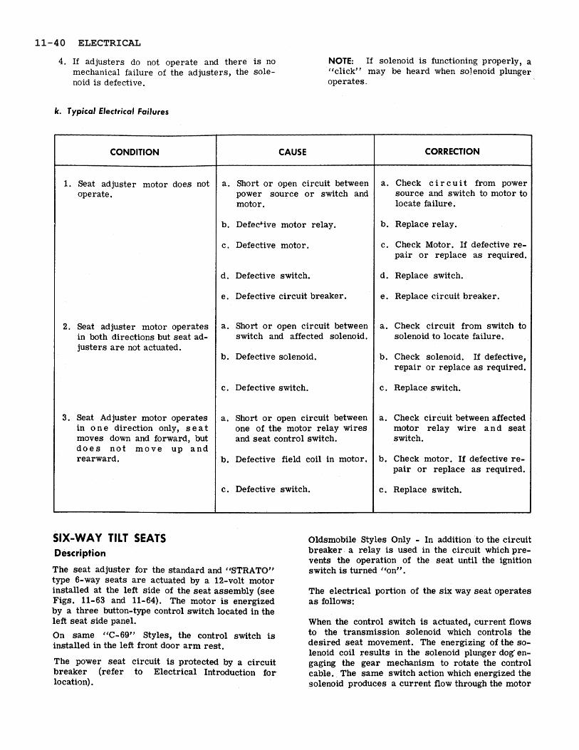
k. Typical Electrical Failures
SIX-WAY TILT SEATS Description
CONDITION
f . Seat adjuster motor does not operate.
2. Seat adjuster motor operates in both directions but seat ad- justers a re not actuated.
3 . Seat Adjuster motor operates in o n e direction only, s e a t moves down and forward, but d o e s n o t m o v e up a n d rearward.
The seat adjuster for the standard and ('STRATOt7 type 6-way seats a re actuated by a 12-volt motor installed at the left side of the seat assembly (see Figs. 11-63 and 11-64). The motor is energized by a three button-type control switch located in the left seat side panel.
CAUSE
a. Short or open circuit between power source o r switch and motor.
b. DefecCive motor relay.
c. Defective motor.
d. Defective switch.
e. Defective circuit breaker.
a . Short o r open circuit between switch and affected solenoid.
b. Defective solenoid.
c. Defective switch.
a . Short o r open circuit between one of the motor relay wires and seat control switch.
b. Defective field coil in motor.
c. Defective switch.
CORRECTION
a. Check c i r c u i t from power source and switch to motor to locate failure.
b. Replace relay.
c. Check Motor. If defective re- pair or replace a s required.
d. Replace switch.
e . Replace circuit breaker.
a . Check circuit from switch to solenoid to locate failure.
b. Check solenoid. If defective, repair or replace a s required.
c. Replace switch.
a. Check circuit between affected motor relay wire a n d seat switch.
b. Check motor. If defective re- pair or replace a s required.
c. Replace switch.
On same "C-69" Styles, the control switch is installed in the left front door a rm rest.
4
The power seat circuit is protected by a circuit breaker (refer to Electrical Introduction fo r location).
Oldsmobile Styles Only - In addition to the circuit breaker a relay is used in the circuit which pre- vents the operation of the seat until the ignition switch is turned "on".
The electrical portion of the six way seat operates a s follows:
When the control switch is actuated, current flows to the transmission solenoid which controls the desired seat movement. The energizing of the so- lenoid coil results in the solenoid plunger dog' en- gaging the gear mechanism to rotate the control cable. The same switch action which energized the solenoid produces a current flow through the motor
11-40 ELECTRICAL

Fig. 1 1 -63-Six-Way "S/trato" Seat
1. Control Switch 7. Rear Vertical Control 2. Motor Cable (Blue) 3. Motor Control .Relay 8. Horizontal Control 4. Harness Feed Connector Cable (Black) 5. Rubber Coupler 9. Transmission and Solenoid 6. Frorit Vertical Control Assembly
Cable (Yellow) 10. Ground Wire
control relay to one of the motor field coils. The current flows through the relay, closes the contacts between the relay power source and the armature motor lead wire, and results in the operation of the seat motor. When the control switch lever is re- leased, the switch contacts open, a spring returns the shaft dog and solenoid plunger to their original position disengaging them from the gear dog.
Circuit Checking Procedures
It may be necessary to use only one o r all of the procedures outlined to locate an electrical failure in the circuit. If the location of the failure is evi- dent, follow only the steps required to check the affected wire or component. If the location of the failure i s not evident, follow the procedure a s out- lined. Before performing any extensive check pro- cedures, check the seat adjuster drive cables for proper attachment. In addition, study the seat cir- cuit diagrams to become familiar with the seat circuit. See Figures 11-65, 11-66 and 11-67.
a. Checking feed Circuit Continuity at Circuit Breaker
1. Connect one test light lead to battery side of circuit breaker and ground other lead. If tester does not light, there is an open o r short cir- cuit in feed circuit to breaker.
2. To check circuit breaker, disconnect the out- put feed wire (the wire opposite the power
Fig. 1 1 -64-Six-Way Standard Bench Seat
1. Horizontal Control Cable (Black)
2. Rear Vertical Control Cable (Blue)
3. Ground Wire 4. Motor 5. Control Switch 6. Front Vertical Control
Cable (Yellow)
7. Motor Control Relay 8. Rubber Coupler 9. Harness Feed
Connector 10. Transmission and
Solenoid Assembly 1 1. Front Vertical Control
Cable (Yellow) 12. Transmission End Plate
source feed to the breaker) from the breaker and with test light check terminal from which the wire was disconnected. If tester does not light, circuit breaker is inoperative. Buick and Cadillac Styles - Check feed circuit continuity at fuse block.
b. Checking Relay Assembly at Shroud- Oldsmobile Styles
1. With test light check relay feed (orange-black stripe). If tester does not light, there is an open or short circuit between relay and circuit breaker.
2. Turn ignition switch on and with test light check output terminal of relay (red-white stripe). If tester does not light, the relay is inoperative o r there is a short o r open circuit between ignition switch (pink) and relay as- sembly. (Check fuse at dash panel).
c. Check feed Circuit Continuity at Seat Control Switch
1. Connect one test light lead to feed terminal of switch block and ground other test lead to body metal.
2. If tester does not light, there is an open or short circuit between switch and power source.
ELECTRICAL 11-41

Fig. 11-65-Six-Way Seat Circuit - A l l Except Oldsmobile Styles
SOLENOID IDENTIFICATION * TRANSMISSION u CLUTCH
1 REAR VERTICAL SOLENOID 2 HORIZONTAL SOLENOID
CONTROL SOLENOIDS
3 FRONT VERTICAL SOLENOID
CIRCUIT BREAKER
SEAT ADJUSTER
ARMATURE FEED - RED
d. Checking the Seat Control Switch
SIX - WAY SEAT SWITCH TERMINAL BLOCK
NOTE: In the following operations which specify the seat control switch to be actuated, a switch that has been checked for proper operation may be connected to the switch block. If a switch is not available, a three-way jumper wire can be made to perform the switch function. The jumper wire and the switch locations to be connected to obtain a specific movement of the seat a re shown in Figures 11-69 - Oldsmobile styles with switch in seat side panel; 11-70 - Oldsmobile styles with switch in arm rest; 11-68 - Chevrolet, Pontiac, Buick and Cadillac styles. If a jumper wire is used, letter the locations on the switch block a s indicated in the illustration. Details outlining the making and use of the jumper wire follow the checking procedure.
1. Obtain switch or jumper wire and connect to switch block.
1821 A
No ' 7 14 20 21 22 24
2. Operate switch. If adjusters operate with new switch o r jumper wire, but did not operate with original switch, the original switch is defective.
3. Check all six movements of seat adjuster.
COLOR
DARKGREEN
ORANGE- BLACK. YELLOW LIGHT GREEN TAN LIGHT BLUE
e. Checking Feed Circuit Continuity at Relay on Seat Motor
1 '1 FUNCTION
F I E L D F E E D - F O R W A R D 8 U P W A R D FEED FIELD FEED-REARWARD 8 D O W N SOLENOID - FRONT EDGE VERTICAL SOLENOID - REAR EDGE VERTICAL SOLENOID - HORIZONTAL MOVEMENT
1. Disengage 3-wire connector body from the seat motor relay terminal.
2. Insert one test light lead into the relay power feed connector slot on the harness, and ground the other test light lead.
11-42 ELECTRICAL

f SOLENOID IDENTIFICATION
1 R E A R V E R T I C A L SOLENOID T R A N S M I S S I O N & C L U T C H 2 H O R I Z O N T A L SOLENOID CONTROL SOLENOIDS 3 F R O N T V E R T I C A L SOLENOID
TO I G N I T I O N CIRCUIT T E R M I N A L ON B R E A K E R F U S E BLOCK
S E A T A D J U S T E R
ARMATURE F E E D . R E D
R E L A Y
Fig. 11-66-Six-Way Seat Circuit - Switch i n Arm Rest - Oldsmobile Styles
3. If tes ter does not light, there is no current at 9. Checking the Relay Assembly end of feed wire. Failure is caused by an open o r short in feed circuit. 1. Disconnect three motor leads from relay as-
sembly. These a r e the wires leading from the motor to the relay.
f. Checking Wires Between Control Switch and Motor Relay
1. Disengage 3-wire harness connector from re- lay at motor.
2. Insert one test light lead into the motor field connector slot on harness and ground the other lead.
3. Actuate seat switch to energize field wire being tested.
2. Connect one end of a jumper wire to one of the motor field feed studs on the relay and ground the other end of the jumper wire.
3. Connect one end of tes t light to motor arma- ture feed stud on relay and ground other tester lead.
4. With a jumper wire, energize the field stud which is not grounded. If tes ter does not light the relay is defective.
4. If tes ter does not light, there is no current a t h. Checking the Motor Assembly end of wire. Failure is caused by an open o r short circuit between end of wire and switch. 1. Disconnect the motor armature feed lead and Check other motor field wire in the same one of the motor field feeds from the relay manner. assembly.
ELECTRICAL 11-43

SOLENOID IDENTIFICATION
2 HORIZONTAL SOLENOID CONTROL SOLENOIDS 3 FRONT VERTICAL SOLENOID
- - TO IGNITION T E R M I N A L ON F U S E BLOCK
FIELD F E E D S
E E D - R
2236
Fig. 11-67-Six-Way Seat Circuit - Switch in Seat Side Panel - Oldsmobile Styles
2. With a jumper wire, energize the armature j. Checking the Solenoid feed and one of the field feeds.
3. If motor does not operate, it is defective. 1. Check solenoid ground strap attachment for Check the other motor field feed in the same proper ground. manner.
2. Energize solenoid being checked with jumper i. Checking the Wire Between the Solenoid and Switch
wire.
1. D i s e n g a g e h a r n e s s connector f r o m transmission.
2. Connect one test light lead to end of harness wire being tested and ground other lead.
3. Operate switch to energize wire being tested. If tester does not light, there is no current at end of wire. Failure is caused by an open o r short circuit between end of wire and switch.
NOTE: If solenoid is functioning, a ((click') should be heard when solenoid, plunger oper- ates ('in" and ((out)).
CAUTION: To prevent damaging the solenoid, do not energize solenoid for more than one minute.
3. With solenoid energized, actuate seat control switch to energize adjuster motor.
11-44 ELECTRICAL

- SIX-WAY SEAT CONTROL SWITCH BLOCK
JUMPER WIRE
JOIN ONE END AS SHOWN
LOCATION WIRE COLOR FUNCTION
A ORANGE-BLACK SWITCH FEED B LIGHT BLUE SOLENOID-HORIZONTAL MOVEMENT C YELLOW * FIELD FEED-REARWARD & DOWN CYCLE D TAN SOLENOID-REAR EDGE VERTICAL CYCLE E LIGHT GREEN SOLENOID-FRONT EDGE VERTICAL CYCLE F DARK GREEN * FIELD FEED-FORWARD & UP CYCLE
* O N STY LES WITH SWITCH IN ARM REST- DARK GREEN CONTROLS FORWARD& UP CYCLE YELLOW FIELD CONTROLS REARWARD & DOWN CYCLE 1825
Fig. 11-68-Six-Way Seat Switch Block - A l l Styles Except Oldsmobile
4. If adjusters do not operate, and there is no switch feed location, one of the motor field wire mechanical failure in the seat unit, the sole- locations and one of the solenoid locations must noid is defective. be connected simultaneously.
Three- Way Jumper Wire for Checking Seat Switch On Bodies with Switch in Seat Side Panel:
To make jumper wire, obtain two pieces of #12 gauge wire, each 4 1/2" long, join one end of each 1. To raise front edge of seat, place jumper in
wire as shown in Figure 11-68. The joined end can locations, A, F and E.
be inserted in the feed location in the switch block; one of the remaining ends can be inserted into one 2. To lower front edge of seat, place jumper in
of the field locations in the switch block; the other locations A, C and E.
end can be inserted into one of the solenoid locations.
3. To raise rear edge of seat, place jumper in locations A, F and D.
IMPORTANT: To obtain a seat movement using 4. To lower rear edge of seat, place jumper in a 3-way jumper wire at the switch block, the locations A, C and D.
ELECTRICAL 11-45

SIX-WAY SEAT CONTROL SWITCH BLOCK
JUMPER WlRE
JOlN ONE END AS SHOWN
LOCATION WIRE COLOR FUNCTION
A PINK SWITCH FEED B LIGHT BLUE SOLENOID-HORIZONTAL MOVEMENT C YELLOW FIELD FEED-REARWARD & DOWN CYCLE E TAN SOLENOID-REAR EDGE VERTICAL CYCLE
F LIGHT GREEN SOLENOID-FRONT EDGE VERTICAL CYCLE D DARK GREEN FIELD FEED-FORWARD & UP CYCLE
1826
Fig. 11-69-Six-Way Seat Switch Block - Switch i n Seat Side Panel - Oldsmobile
I Fig. 11-70-Six-Way Seat Switch Block - Switch in Arm Rest - Oldsmobile
JUMPER WlRE
JOlN ONE END AS SHOWN
LOCATION WIRE COLOR FUNCTION
A PINK SWITCH FEED B LIGHT BLUE SOLENOID-HORIZONT AL MOVEMENT C DARK GREEN FIELD FEED-FORWARD & UP CYCLE D TAN SOLENOID-REAR EDGE VERTICAL CYCLE E LIGHT GREEN SOLENOID-FRONT EDGE VERTICAL CYCLE F YELLOW FIELD FEED-REARWARD & DOWN CYCLE
1827
,
11-46 ELECTRICAL

5. To move seat forward, place jumper in loca- tions A- B and F.
6. To move seat rearward, place jumper in lo- cations A- C and B.
On Bodies with Switch in Arm Rest:
1. To raise front edge of seat, place jumper in locations A- C and E.
2. To lower front edge of seat, place jumper in locations A- F and E.
3. To raise rear edge of seat, place jumper in locations A- C and D.
4. To lower rear edge of seat, place jumper in locations A- F and D.
5. To move seat forward place jumper in loca- tions A- C and B.
6. To move seat rearward, place jumper in lo- cations A - F and B.
Typical Electrical Failures
CONDITION
Seat adjuster motor does not operate.
Seat adjuster motor operates, but seat adjusters are not actuated.
or
Seat adjuster motor o p e r a t e s, front edge of seat moves up and down and seat moves forward and rearward. The rear edge of seat cannot be operated.
Seat adjuster motor operates and seat adjusters move front and rear edge of seat up and forward but will not move the seat down and rearward.
or
Seat adjuster motor operates and seat adjusters move front and rear of seat down and rearward, but will not move the seat up and forward.
CAUSE
a. Short o r open circuit between power source or switch and motor.
b. Defective motor.
a. Short o r open circuit between switch and affected solenoid.
b. Defective solenoid.
a. Short or open circuit between one of the motor field wires and seat control switch.
b. Defective field coil in motor.
CORRECTION
a. Check circuit from pow e r source and switch to motor to locate failure.
b. Check ignition switch circuit through relay at left shroud - Oldsmobile styles only.
c. Check motor. If defective, re- pair o r replace as required.
a. Check circuit from switch to solenoid to locate failure.
b. Check solenoid. If defective, repair or replace a s required.
a. Check circuit between affected m9tor field wire and seat switch.
b. Check motor. If defective, re- pair o r replace a s required.
ELECTRICAL 11-47

ELECTRIC FOLDING TOP-CORVAIR
DESCRIPTION
The electric folding top assembly is actuated by a 12 volt shunt-wound motor located under the folding top compartment bag (see Fig. 11-71).
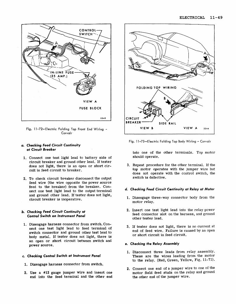
The motor is energized by a control switch mounted on the left side of the instrument panel (see Fig. 11-72). For wiring installation from engine com- partment to instrument panel (see Fig. 11-73).
Checking Procedure
Failures in a circuit a r e usually caused by short circuits o r open circuits. Open circuits a r e usually caused by breaks in the wiring, faulty connection o r mechanical failure in a component such a s a
switch o r circuit breaker. Short circuits a re usually caused by wires from different components of the circuit contacting one another o r by a wire o r component grounding to the metal of the body due to a screw through the wire, insulation cut through by sharp metal edge, etc.
It may be necessary to use only one o r all of the procedures outlined to locate an electrical failure in the circuit. If the location of the failure is evi- dent follow only the steps required to check the affected wire o r component. If the location of the failure is not evident, follow the procedure a s out- lined. Be sure to check the harness connectors fo r proper engagement, become familiar with the typical circuit diagram (see Fig. 11-74) and dis- engage drive cables a t motor actuator assembly to relieve any mechanical bind.
Fig. 11-71-Electric Folding Top Motor and Actuator - Corvair
11-48 ELECTRICAL
FUSE BLOCK
Fig. 11-72-Electric Folding Top Front End Wiring - Corvai r
Fig. 11-73-Electric Folding Top Body Wiring - Corvair a. Checking Feed Circuit Continuity
at Circuit Breaker
1. Connect one test light lead to battery side of circuit breaker and ground other lead. If tester does not light, there is an open o r short cir- cuit in feed circuit to breaker.
2. To check circuit breaker disconnect the output feed wire (the wire opposite the power source feed to the breaker) from the breaker. Con- nect one test light lead to the output terminal and ground other lead. If tester does not light, circuit breaker is inoperative.
6. Checking Feed Circuit Continuity at Control Switch on Instrument Panel
1. Disengage harness connector from switch. Con- nect one test light lead to feed terminal of switch connector and ground other test lead to body metal. If tester does not light, there is an open o r short circuit between switch and power source.
c. Checking Control Switch at Instrument Panel
1. Disengage harness connector from switch.
2. Use a #12 gauge jumper wire and insert one end into the feed terminal and the other end
into one of the other terminals. Top motor should operate.
3. Repeat procedure for the other terminal. If the top motor operates with the jumper wire but does not operate with the control switch, the switch is defective.
d. Checking Feed Circuit Continuity at Relay at Motor
1. Disengage three-way connector body from the motor relay.
2. Insert one test light lead into the relay power feed connector slot on the harness, and ground other tester lead.
3. If tester does not light, there is no current at end of feed wire. Failure is caused by an open o r short circuit in feed circuit.
e. Checking the Relay Assembly
1. Disconnect three leads from relay assembly. These are the wires leading from the motor to the relay. (Red, Green, Yellow, Fig. 11-71).
2. Connect one end of a jumper wire to one of the motor field feed studs on the relay and ground the other end of the jumper wire.
ELECTRICAL 11-49
3. Connect one test light lead to motor armature f. Checking the Motor Assembly feed stud on relay a id ground other tester lead. 1. Disconnect motor field feed wires from motor
(at relay). 4. With jumper wire, energize the field stud which 2. Connect one end of a #12 gauge jumper wire
is not grounded. to battery positive pole and other end to one of the motor field and the armature wires.
CAUTION: Do not energize grounded side, if 3. If motor does not operate, motor is defective. tester does not light, the relay is defective. Check the remaining motor field wire in the
same manner.
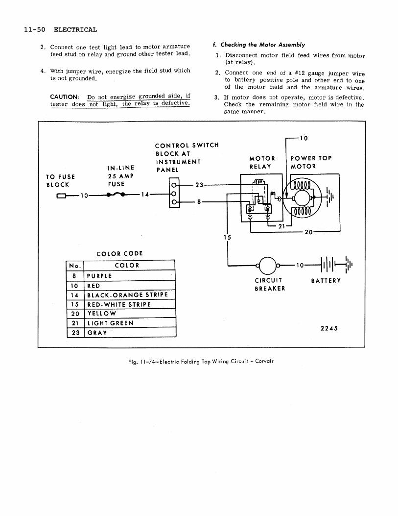
Fig. 1 1 -74-Electric Folding Top Wiring Circuit - Corvair
C O N T R O L SWITCH BLOCK AT INSTRUMENT
I N - L I N E PANEL TO FUSE 2 5 AMP BLOCK
1 - 1 0 1 4
15
COLOR C O D E
o-,l, I +:Il CIRCUIT BATTERY BREAKER
2 2 4 5
1
11-50 ELECTRICAL