electrical technology (eet 103) pn haziah abdul hamid
TRANSCRIPT
ELECTRICAL TECHNOLOGY
(EET 103)PN HAZIAH ABDUL HAMID

SYLLABUS – PART II

SYLLABUS
•TOPIC 4: THREE PHASE CIRCUIT•TOPIC 5: TRANSFORMER•TOPIC 6: ELECTRICAL MACHINES

TOPIC 4: THREE PHASE CIRCUIT

SINGLE PHASE TWO WIRE
pV
SINGLE PHASE SYSTEM
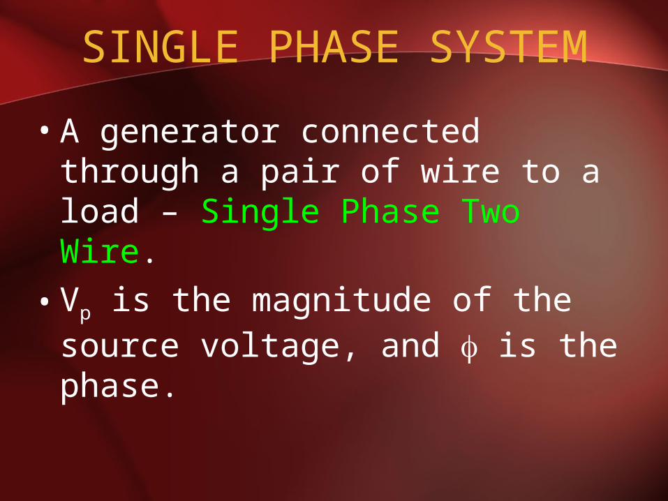
• A generator connected through a pair of wire to a load – Single Phase Two Wire.
• Vp is the magnitude of the source voltage, and is the phase.

SINLGE PHASE THREE WIRE
pV
pV

SINGLE PHASE SYSTEM• Most common in practice: two
identical sources connected to two loads by two outer wires and the neutral: Single Phase Three Wire.
• Terminal voltages have same magnitude and the same phase.
POLYPHASE SYSTEM
•Circuit or system in which AC sources operate at the same frequency but different phases are known as polyphase.
TWO PHASE SYSTEM THREE WIRE
pV
90pV
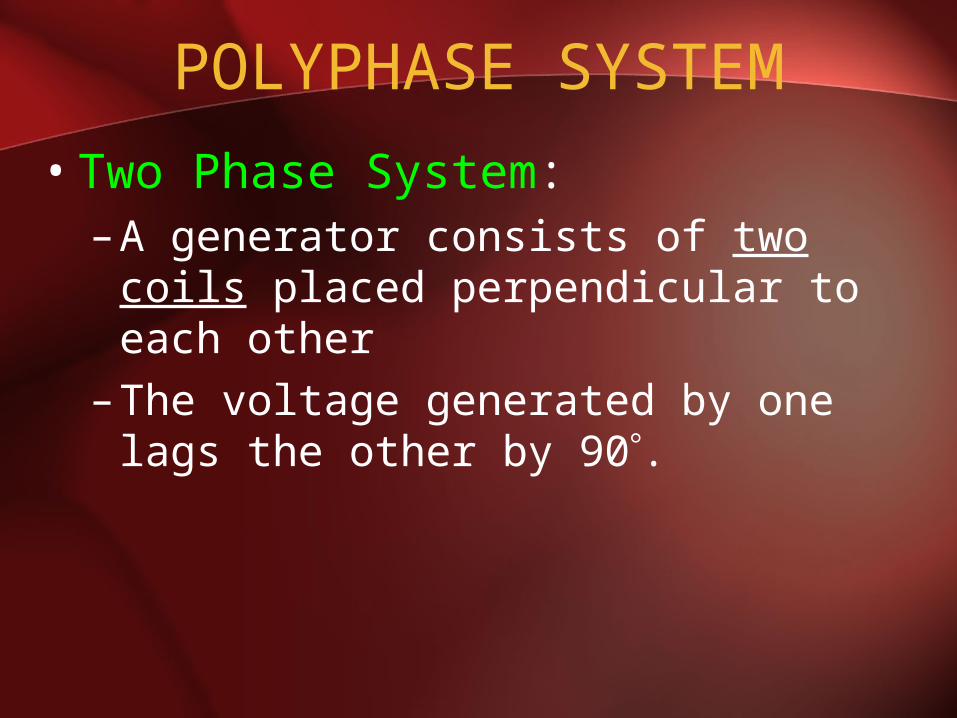
POLYPHASE SYSTEM
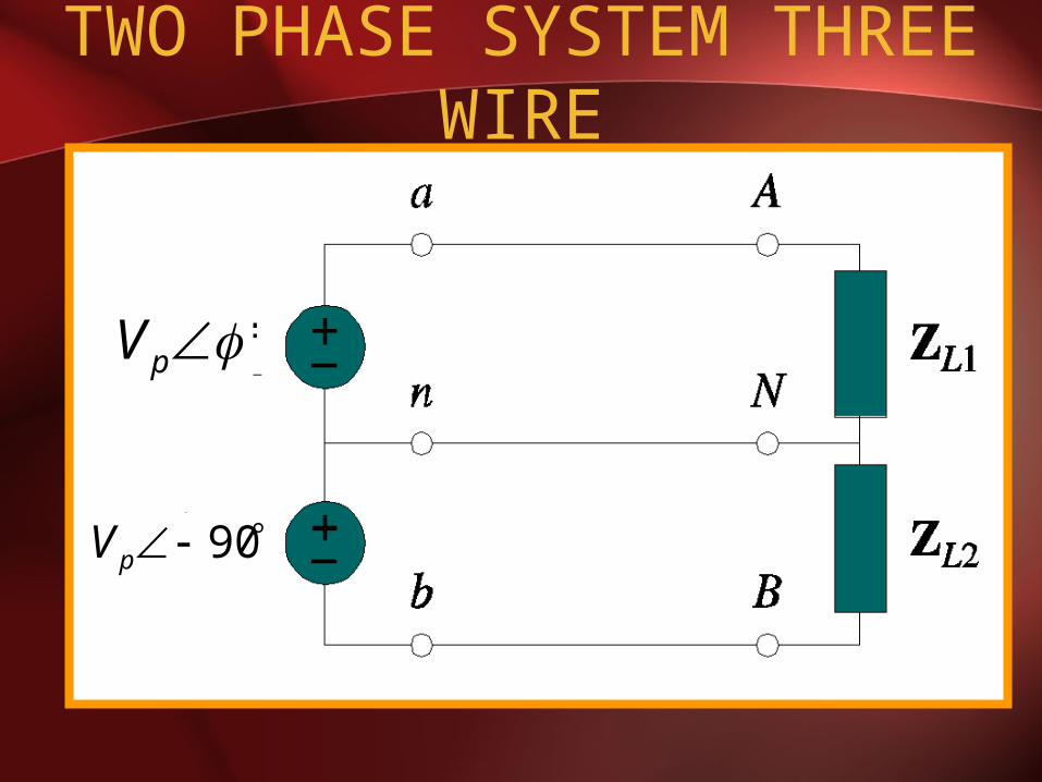
• Two Phase System:– A generator consists of two coils
placed perpendicular to each other– The voltage generated by one lags
the other by 90.
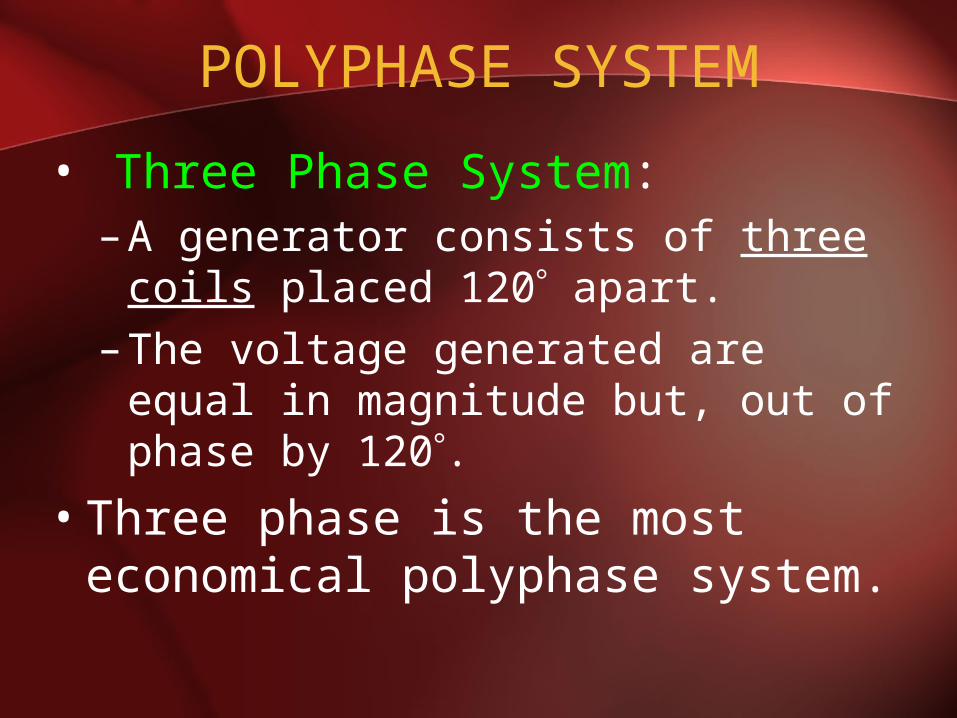
POLYPHASE SYSTEM
• Three Phase System:– A generator consists of three coils
placed 120 apart.– The voltage generated are equal in
magnitude but, out of phase by 120.
• Three phase is the most economical polyphase system.
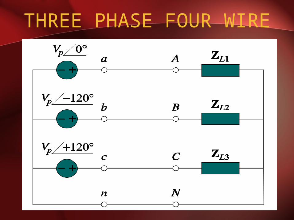
THREE PHASE FOUR WIRE
IMPORTANCE OF THREE PHASE SYSTEM
• All electric power is generated and distributed in three phase.– One phase, two phase, or more than
three phase input can be taken from three phase system rather than generated independently.
– Melting purposes need 48 phases supply.
IMPORTANCE OF THREE PHASE SYSTEM
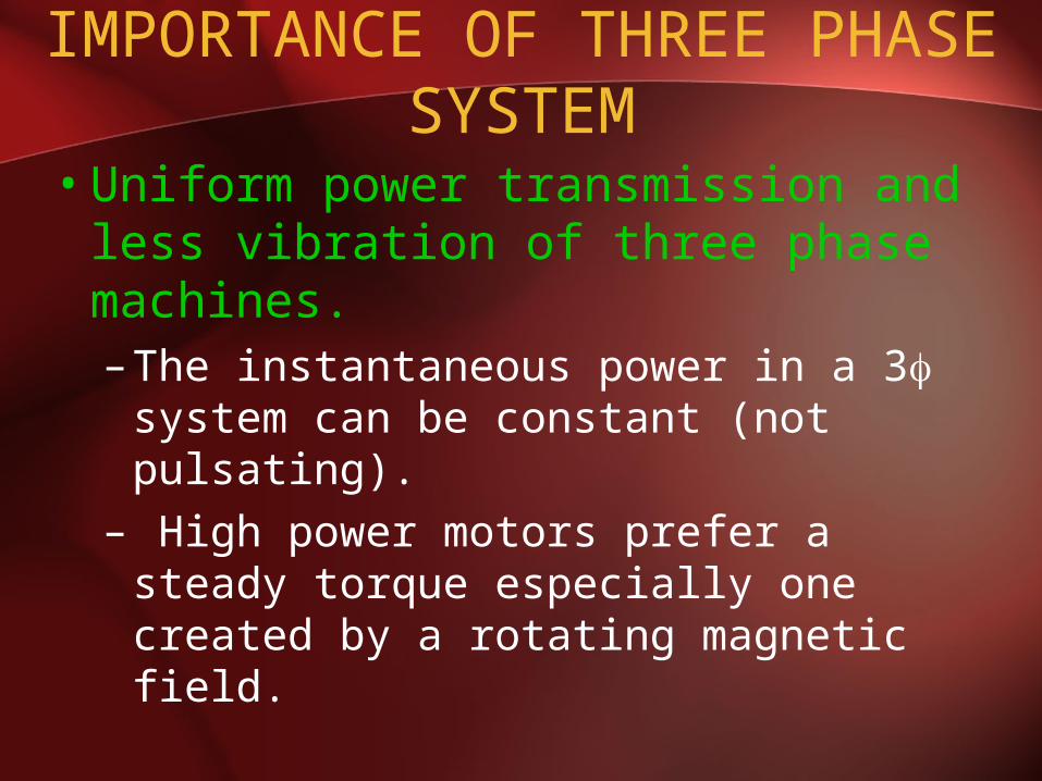
• Uniform power transmission and less vibration of three phase machines.– The instantaneous power in a 3
system can be constant (not pulsating).
– High power motors prefer a steady torque especially one created by a rotating magnetic field.

IMPORTANCE OF THREE PHASE SYSTEM
• Three phase system is more economical than the single phase.– The amount of wire required for a
three phase system is less than required for an equivalent single phase system.
– Conductor: Copper, Aluminum, etc

THREE PHASE GENERATION

FARADAYS LAW• Three things must be present in
order to produce electrical current:a) Magnetic fieldb) Conductorc) Relative motion
• Conductor cuts lines of magnetic flux, a voltage is induced in the conductor
• Direction and Speed are important
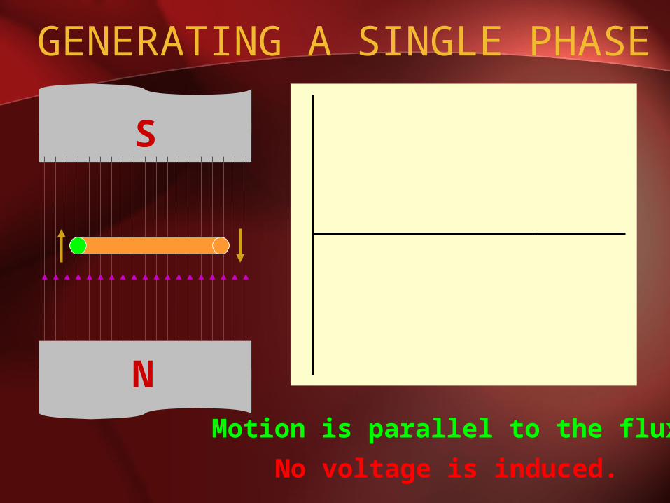
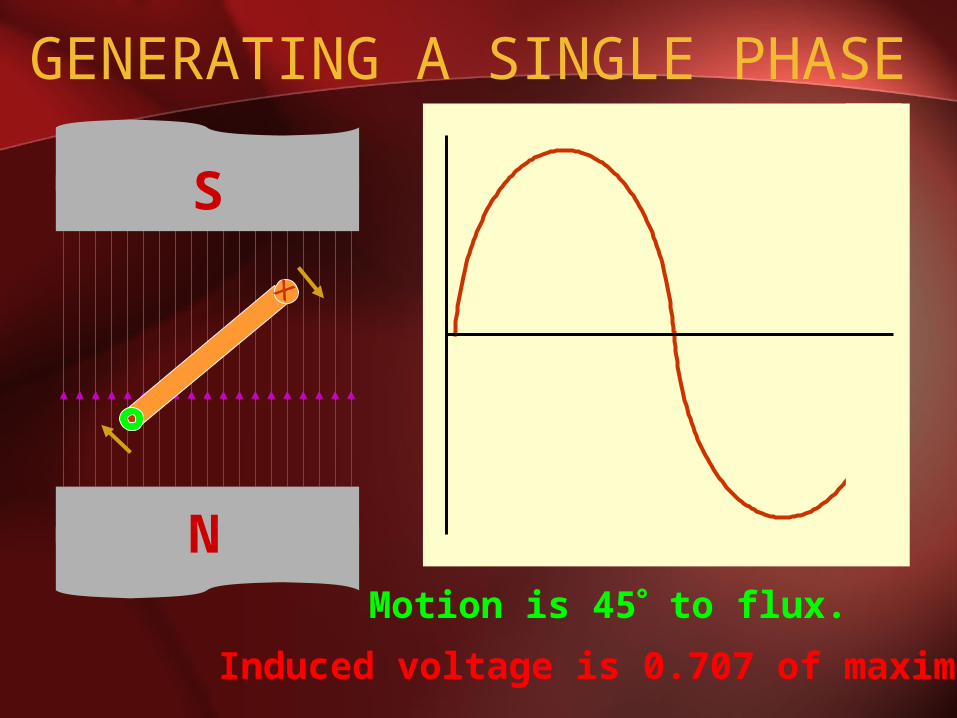
GENERATING A SINGLE PHASE
Motion is parallel to the flux.
No voltage is induced.
N
S

x
N
S
Motion is 45 to flux. Induced voltage is 0.707 of maximum.
GENERATING A SINGLE PHASE
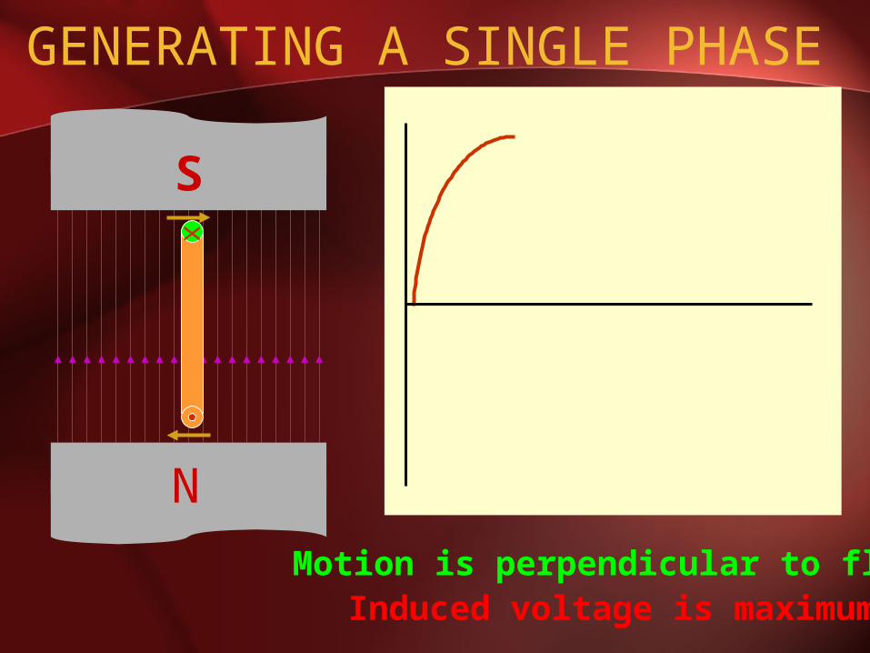
GENERATING A SINGLE PHASE
x
N
S
Motion is perpendicular to flux. Induced voltage is maximum.

GENERATING A SINGLE PHASE
Motion is 45 to flux.
x
N
S
Induced voltage is 0.707 of maximum.

GENERATING A SINGLE PHASE
N
S
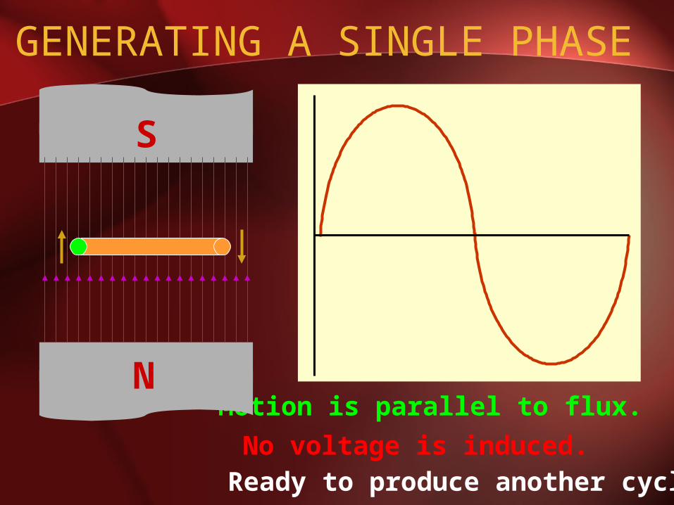
Motion is parallel to flux. No voltage is induced.
GENERATING A SINGLE PHASE
x
N
S
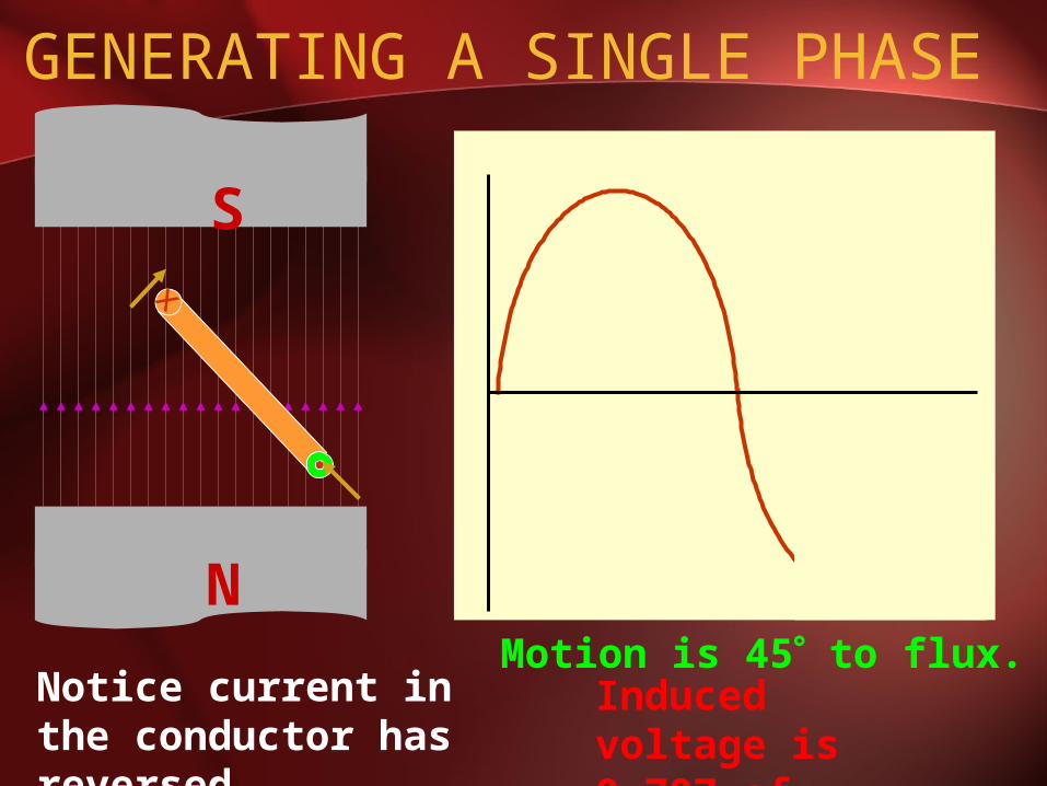
Notice current in the conductor has reversed.
Induced voltage is 0.707 of maximum.
Motion is 45 to flux.

GENERATING A SINGLE PHASE
N
S
x
Motion is perpendicular to flux.
Induced voltage is maximum.
GENERATING A SINGLE PHASE
N
S
x
Motion is 45 to flux.
Induced voltage is 0.707 of maximum.
GENERATING A SINGLE PHASE
Motion is parallel to flux. N
S
No voltage is induced.Ready to produce another cycle.

THREE PHASE GENERATOR

GENERATOR WORK
• The generator consists of a rotating magnet (rotor) surrounded by a stationary winding (stator).
• Three separate windings or coils with terminals a-a’, b-b’, and c-c’ are physically placed 120 apart around the stator.

• As the rotor rotates, its magnetic field cuts the flux from the three coils and induces voltages in the coils.
• The induced voltage have equal magnitude but out of phase by 120.

GENERATION OF THREE-PHASE AC
N
xx
S
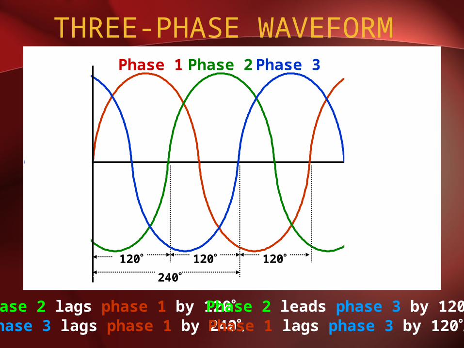
THREE-PHASE WAVEFORM
Phase 2 lags phase 1 by 120 Phase 2 leads phase 3 by 120Phase 3 lags phase 1 by 240 Phase 1 lags phase 3 by 120
Phase 1 Phase 2 Phase 3
120 120 120
240120 120 120
240
Phase 1 Phase 2 Phase 3
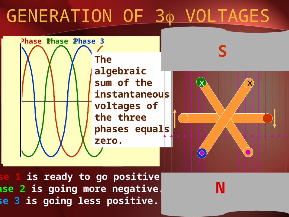
GENERATION OF 3 VOLTAGES
Phase 1 is ready to go positive.Phase 2 is going more negative.Phase 3 is going less positive.
Thealgebraicsum of theinstantaneousvoltages ofthe three phases equalszero.
N
xx
S

THREE PHASE QUANTITIES

BALANCED 3 VOLTAGES
120cos240cos)(
120cos)(
cos)(
tVtVtv
tVtv
tVtv
MMcn
Mbn
Man
• Balanced three phase voltages:– same magnitude (VM )
– 120 phase shift

BALANCED 3 CURRENTS• Balanced three phase currents:
– same magnitude (IM )
– 120 phase shift
240cos)(
120cos)(
cos)(
tIti
tIti
tIti
Mc
Mb
Ma

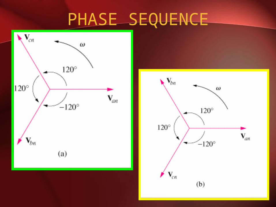
PHASE SEQUENCE
120cos)(
120cos)(
cos)(
tVtv
tVtv
tVtv
Mcn
Mbn
Man
120
120
0
Mcn
Mbn
Man
VV
VV
VV
120
120
0
Mcn
Mbn
Man
VV
VV
VV
POSITIVESEQUENCE
NEGATIVESEQUENCE
PHASE SEQUENCE
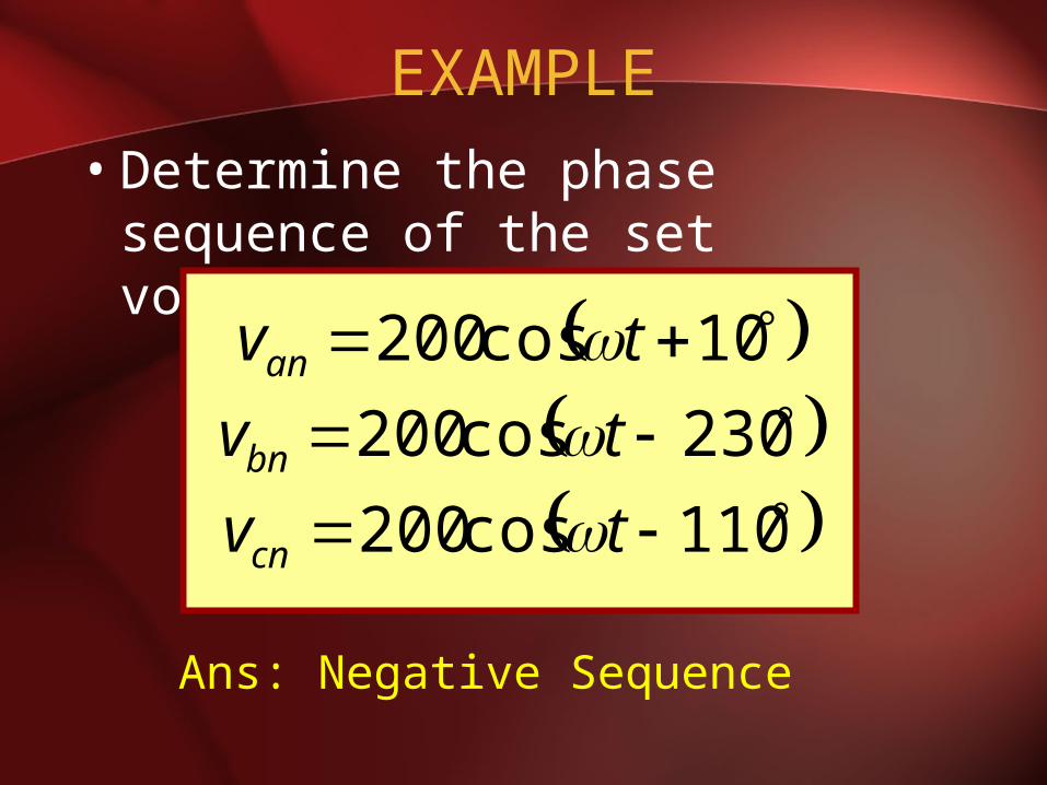
EXAMPLE• Determine the phase sequence
of the set voltages:
110cos200
230cos200
10cos200
tv
tv
tv
cn
bn
an
Ans: Negative Sequence
BALANCED VOLTAGE AND LOAD
• Balanced Phase Voltage: all phase voltages are equal in magnitude and are out of phase with each other by 120.
• Balanced Load: the phase impedances are equal in magnitude and in phase.
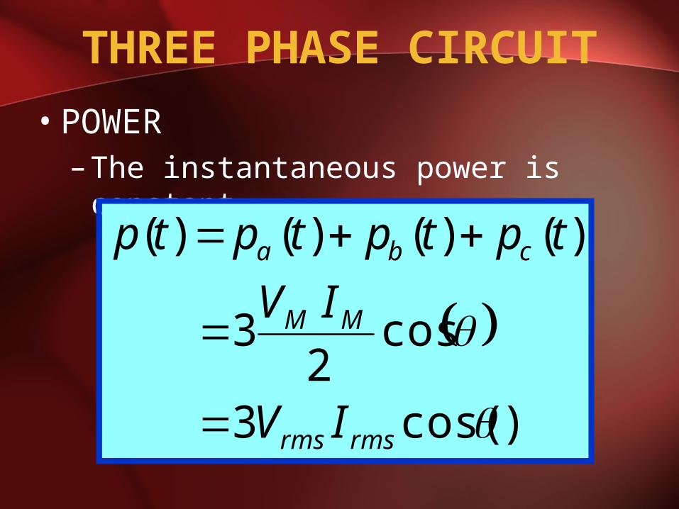
THREE PHASE CIRCUIT
• POWER– The instantaneous power is constant
)cos(3
cos2
3
)()()()(
rmsrms
MM
cba
IV
IV
tptptptp
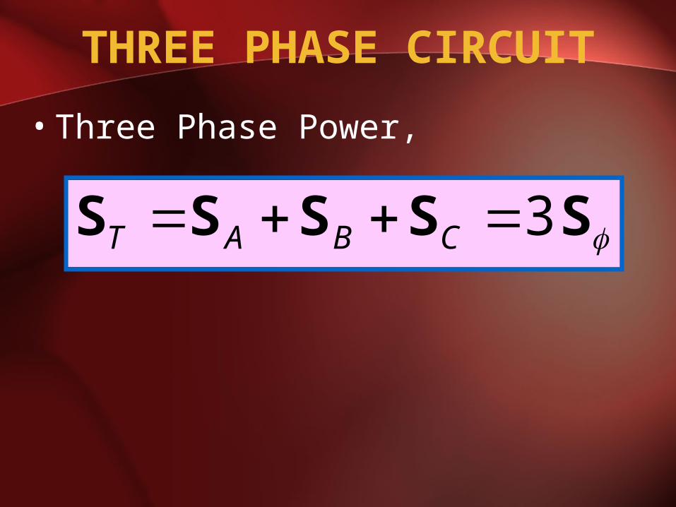
THREE PHASE CIRCUIT
• Three Phase Power,
SSSSS 3 CBAT
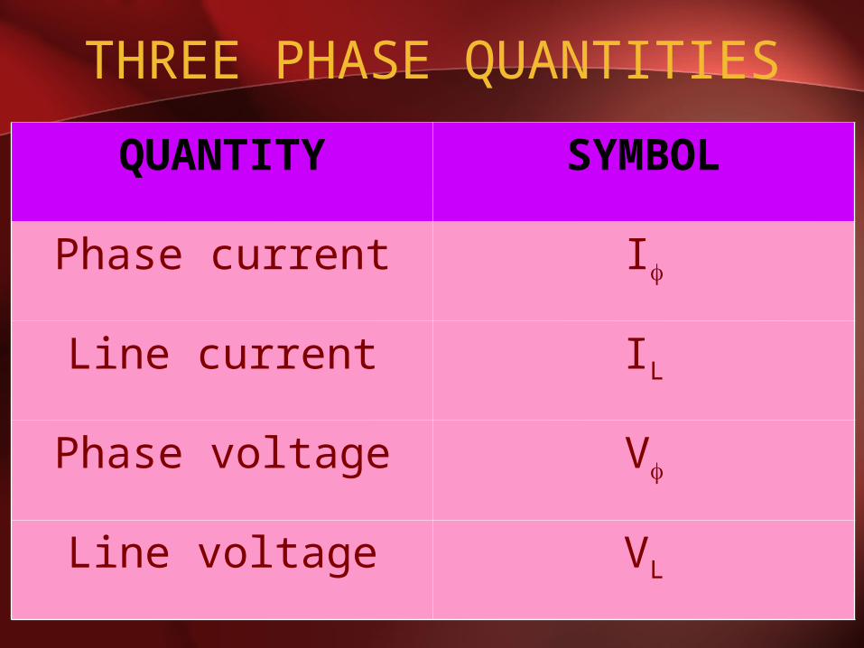
THREE PHASE QUANTITIES
QUANTITY SYMBOL
Phase current I
Line current IL
Phase voltage V
Line voltage VL
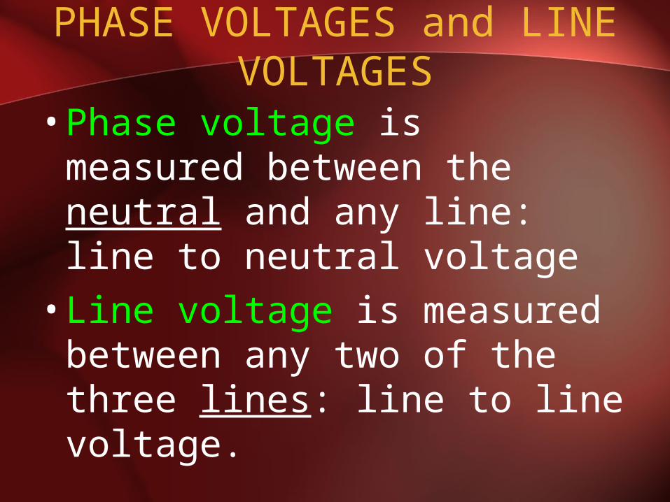
PHASE VOLTAGES and LINE VOLTAGES
•Phase voltage is measured between the neutral and any line: line to neutral voltage
•Line voltage is measured between any two of the three lines: line to line voltage.
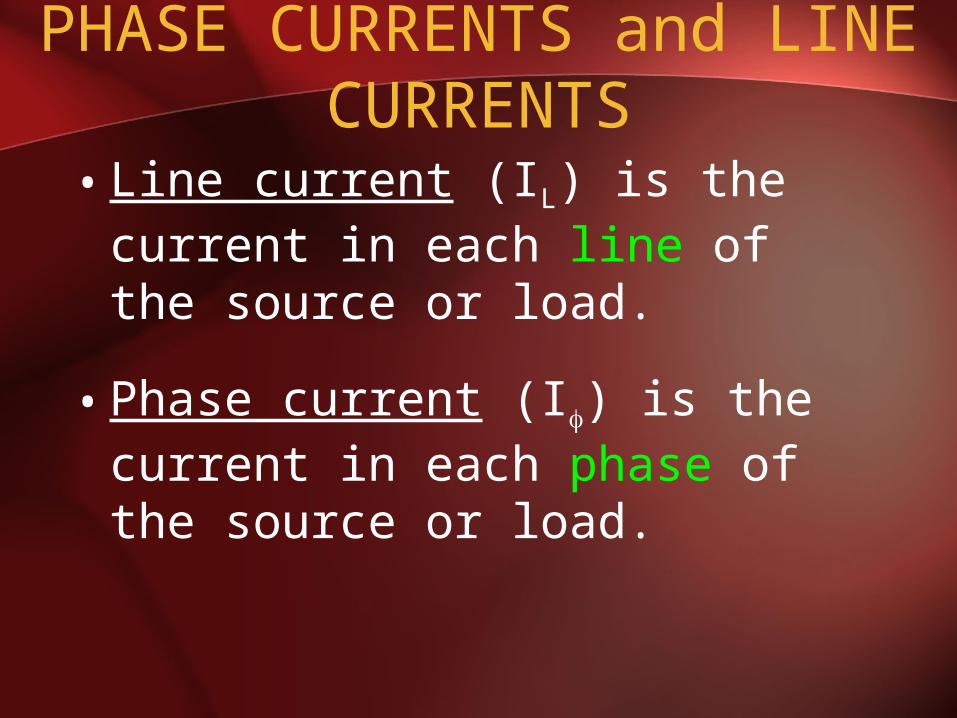
PHASE CURRENTS and LINE CURRENTS
• Line current (IL) is the current in each line of the source or load.
• Phase current (I) is the current in each phase of the source or load.

THREE PHASE CONNECTION
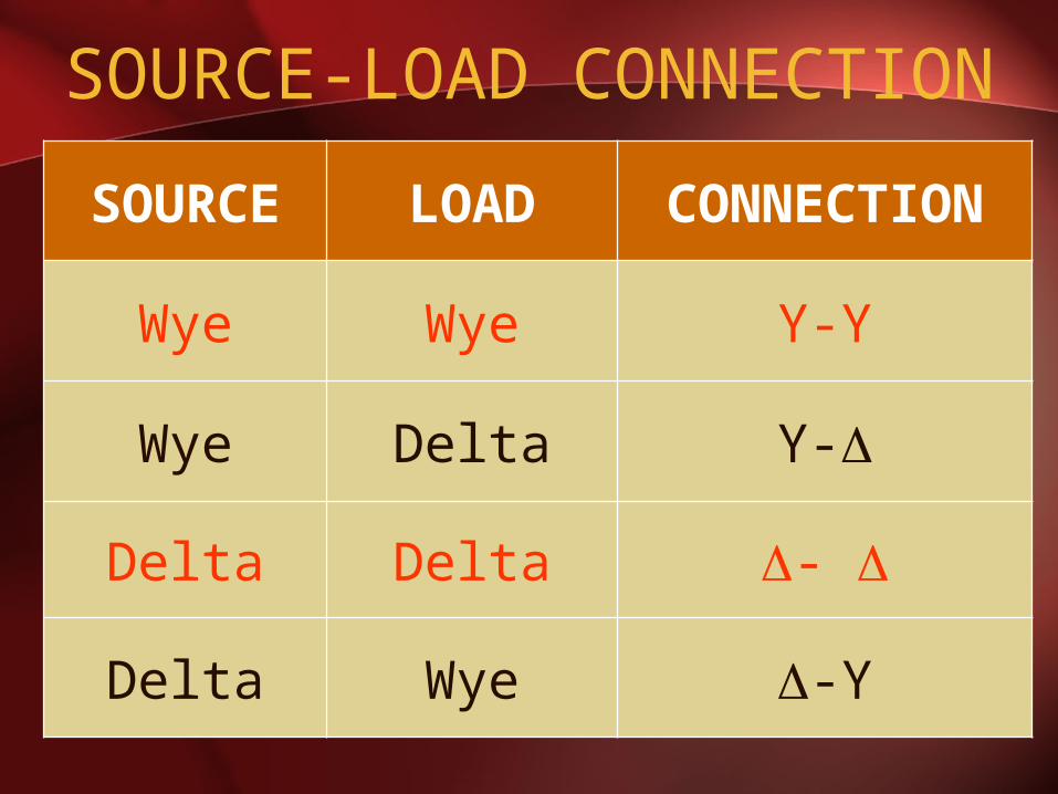
SOURCE-LOAD CONNECTION
SOURCE LOAD CONNECTION
Wye Wye Y-Y
Wye Delta Y-
Delta Delta -
Delta Wye -Y
SOURCE-LOAD CONNECTION
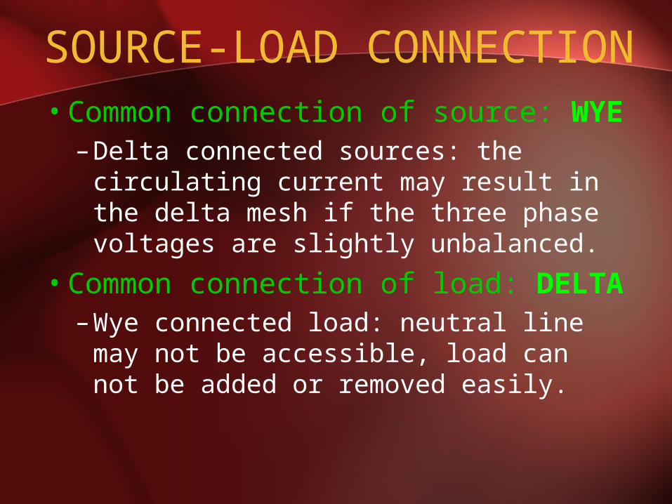
• Common connection of source: WYE– Delta connected sources: the
circulating current may result in the delta mesh if the three phase voltages are slightly unbalanced.
• Common connection of load: DELTA– Wye connected load: neutral line may
not be accessible, load can not be added or removed easily.

WYE CONNECTION
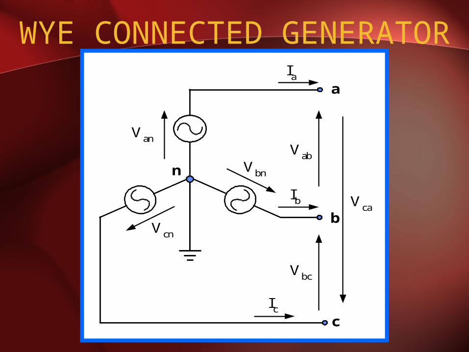
WYE CONNECTED GENERATOR
n
a
b
c
Vab
Vbc
Vca
Vbn
Vcn
Van
Ia
Ib
Ic
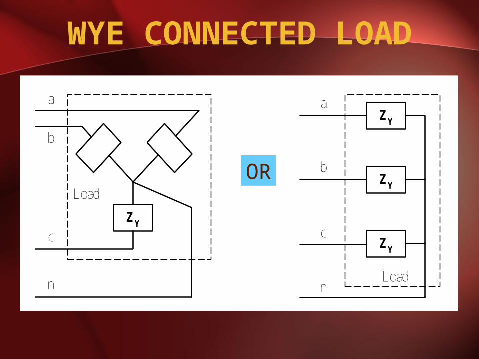
WYE CONNECTED LOAD
ZY
ZY
ZY
a
c
b
nLoad
ZY
a
b
c
Load
n
OR
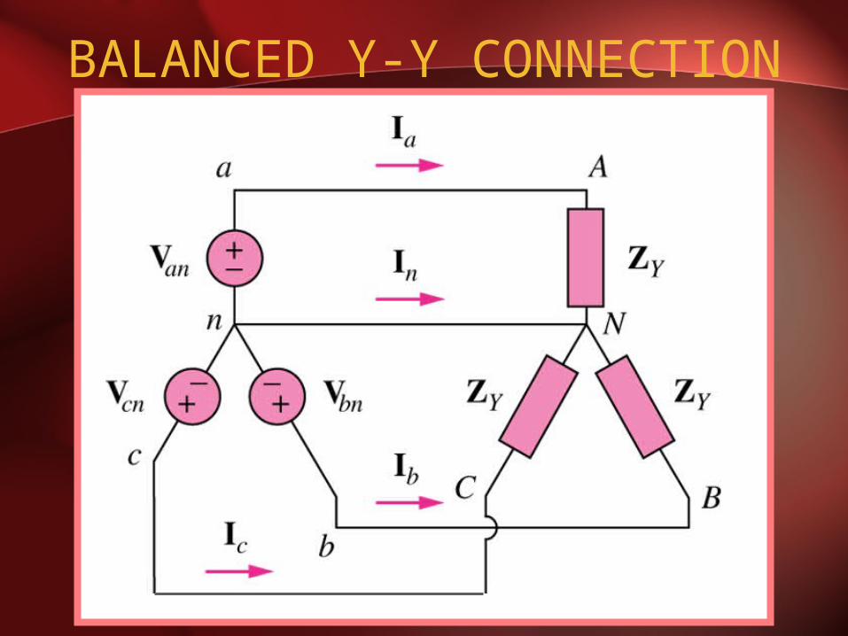
BALANCED Y-Y CONNECTION
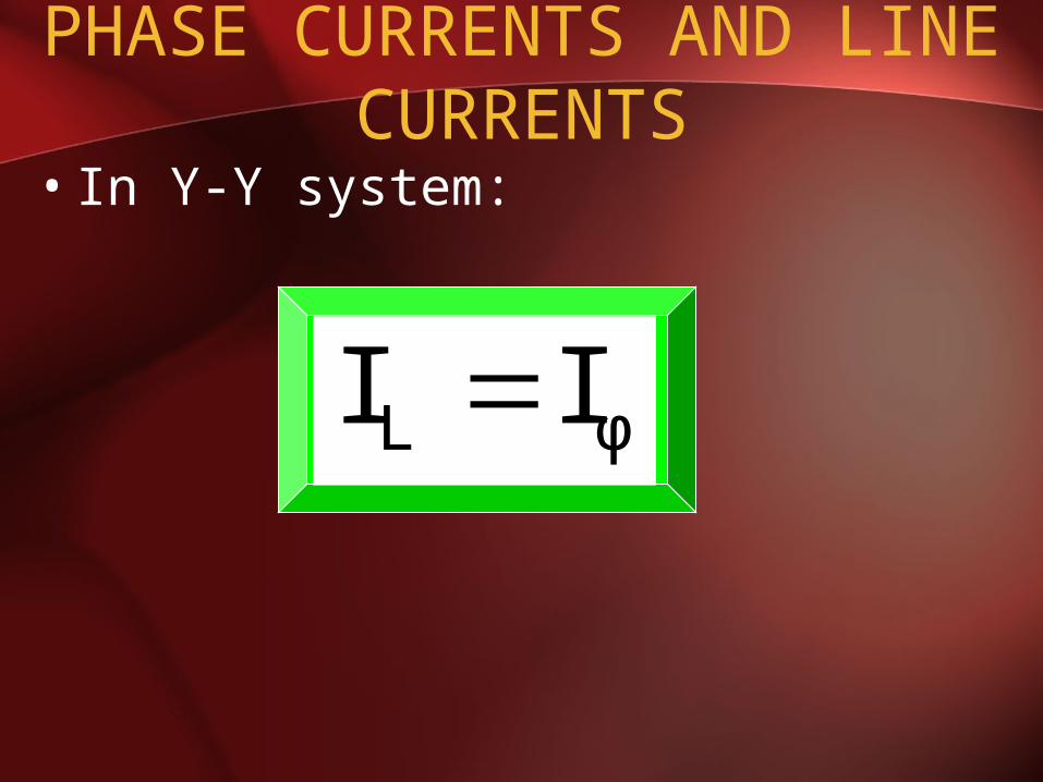
PHASE CURRENTS AND LINE CURRENTS
• In Y-Y system:
φL II
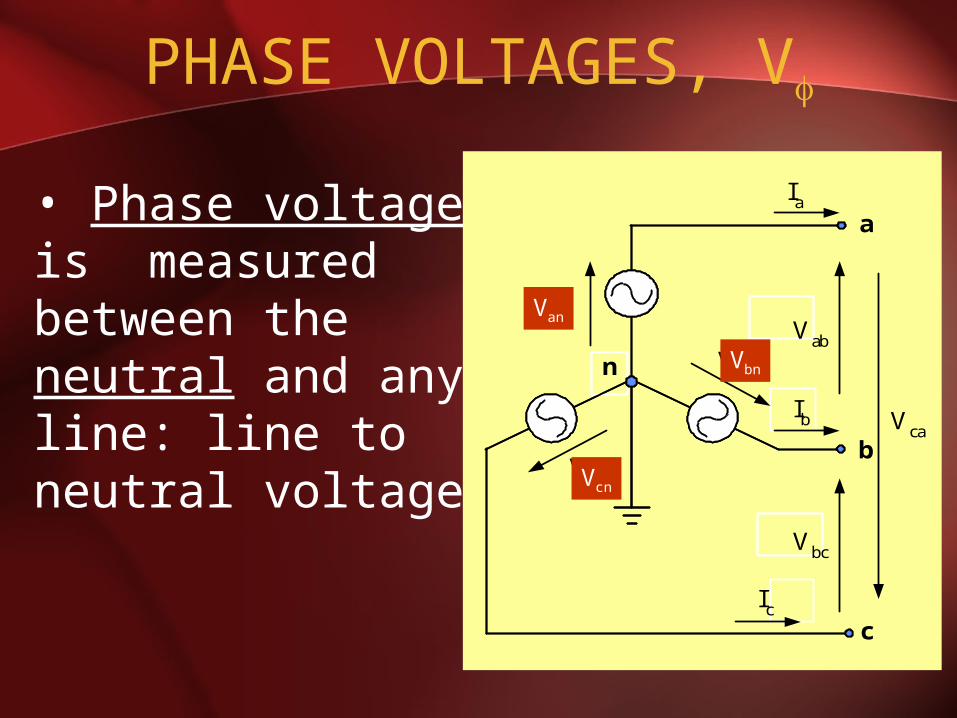
PHASE VOLTAGES, V
• Phase voltage is measured between the neutral and any line: line to neutral voltage
n
a
b
c
Vab
Vbc
Vca
Vbn
Vcn
Van
Ia
Ib
Ic
Van
Vbn
Vcn
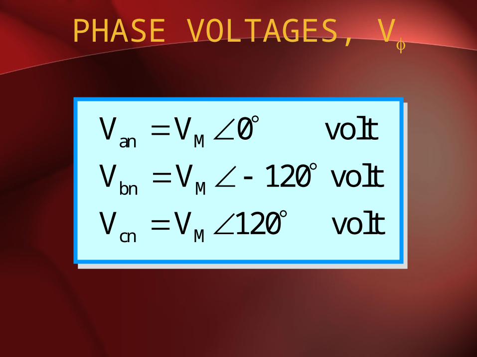
PHASE VOLTAGES, V
an M
bn M
cn M
V V 0 volt
V V 120 volt
V V 120 volt
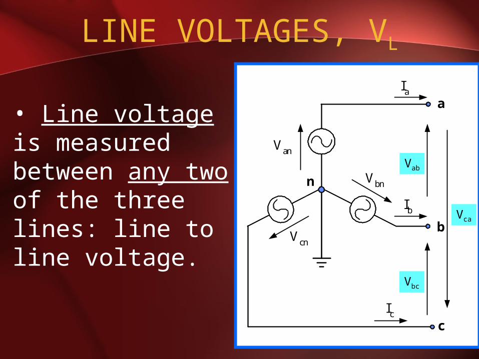
LINE VOLTAGES, VL
• Line voltage is measured between any two of the three lines: line to line voltage.
n
a
b
c
Vab
Vbc
Vca
Vbn
Vcn
Van
Ia
Ib
Ic
Vab
Vbc
Vca
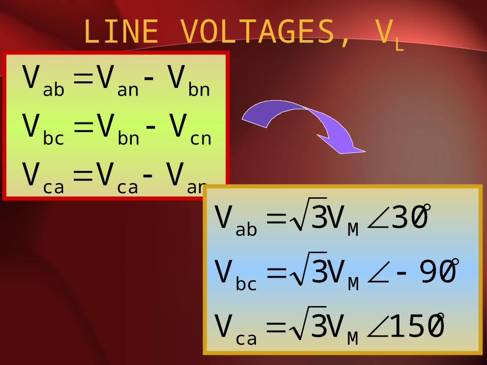
LINE VOLTAGES, VL
ancaca
cnbnbc
bnanab
VVV
VVV
VVV
150V3V
90V3V
30V3V
Mca
Mbc
Mab
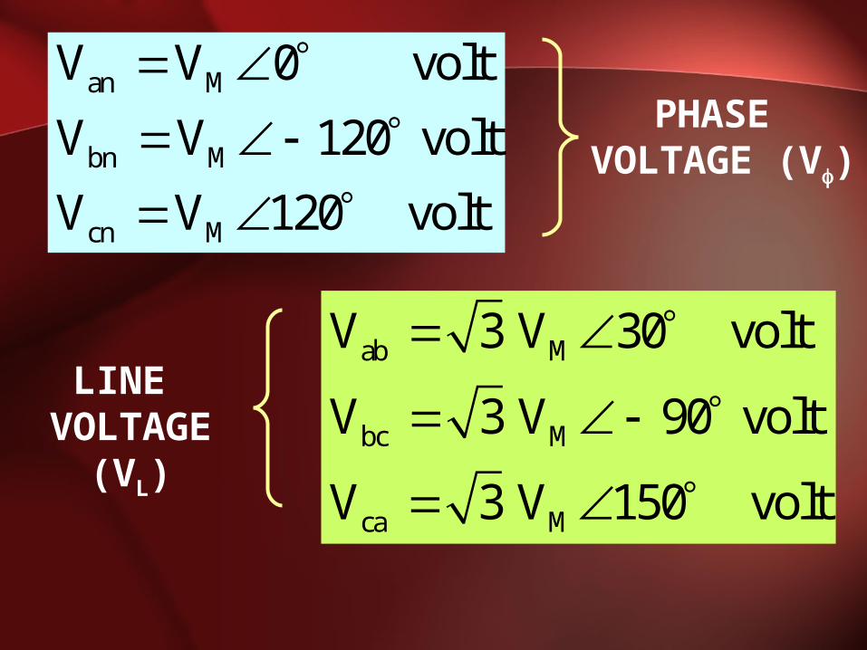
ab M
bc M
ca M
V 3 V 30 volt
V 3 V 90 volt
V 3 V 150 volt
an M
bn M
cn M
V V 0 volt
V V 120 volt
V V 120 volt
PHASE VOLTAGE (V)
LINE VOLTAGE
(VL)

PHASE DIAGRAM OF VL
AND V
30°
120°
Vca Vab
Vbc
Vbn
Van
Vcn
-Vbn
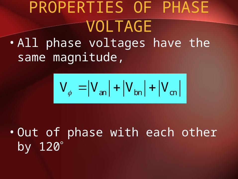
PROPERTIES OF PHASE VOLTAGE
• All phase voltages have the same magnitude,
• Out of phase with each other by 120
an bn cnV V V V

PROPERTIES OF LINE VOLTAGE
• All line voltages have the same magnitude,
• Out of phase with each other by 120
ab bc caV V V VL
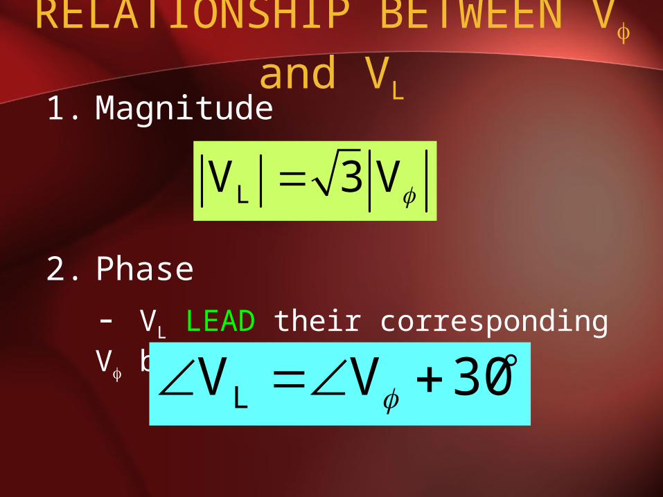
RELATIONSHIP BETWEEN V and VL
1. Magnitude
2. Phase
- VL LEAD their corresponding V by 30
LV 3 V
30VVL
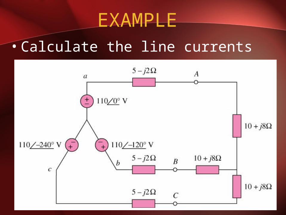
EXAMPLE • Calculate the line currents

Single Phase Equivalent Circuit
• Phase ‘a’ equivalent circuit
5-j2
810 j

21.86.8121.816.155
0110I
Z
VI
a
Y
ana
A2.986.811.8266.81
024II
A141.86.81
120II
ac
ab

DELTA CONNECTION
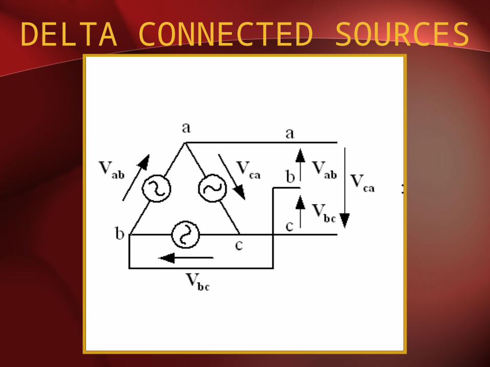
DELTA CONNECTED SOURCES
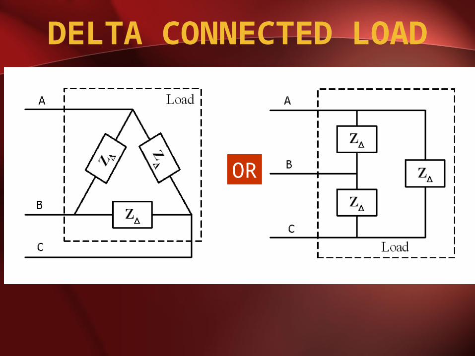
DELTA CONNECTED LOAD
OR
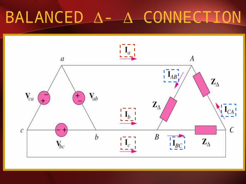
BALANCED - CONNECTION
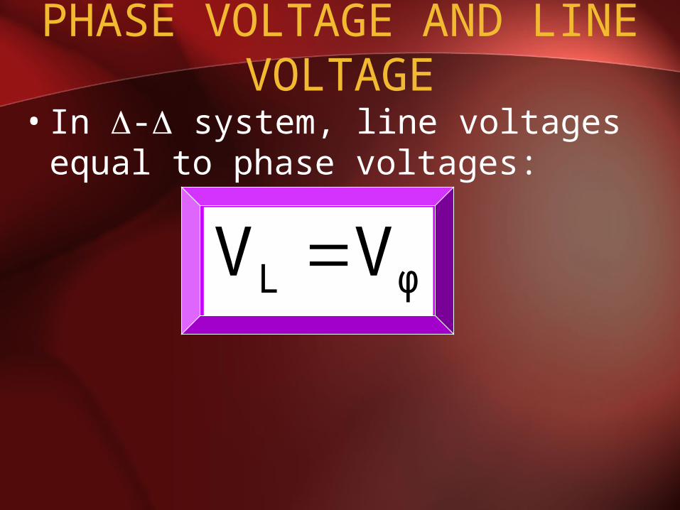
PHASE VOLTAGE AND LINE VOLTAGE
• In - system, line voltages equal to phase voltages:
φL VV

PHASE CURRENTS, I• Line voltages are equal to the
voltages across the load impedances.

PHASE CURRENTS, I• The phase currents are obtained:
Δ
CACA
Δ
BCBC
Δ
ABAB Z
VI,
Z
VI,
Z
VI
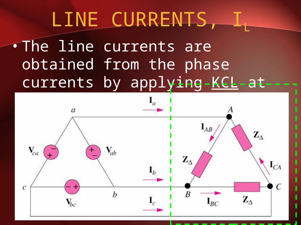
LINE CURRENTS, IL• The line currents are obtained from
the phase currents by applying KCL at nodes A,B, and C.

LINE CURRENTS, IL
BCCAc
ABBCb
CAABa
III
III
III
120I I
120I I
30I 3I
ac
ab
ABa
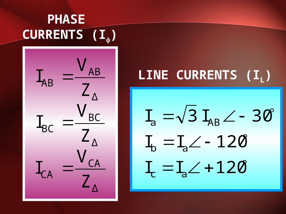
PHASE CURRENTS (I)
LINE CURRENTS (IL)
Δ
CACA
Δ
BCBC
Δ
ABAB
Z
VI
Z
VI
Z
VI
120I I
120I I
30I 3I
ac
ab
ABa
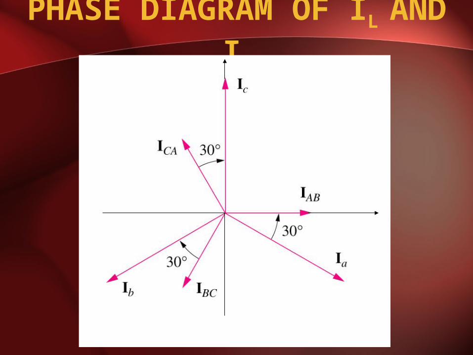
PHASE DIAGRAM OF IL
AND I

PROPERTIES OF PHASE CURRENT
• All phase currents have the same magnitude,
• Out of phase with each other by 120
Δ
φCABCABφ Z
VIIII
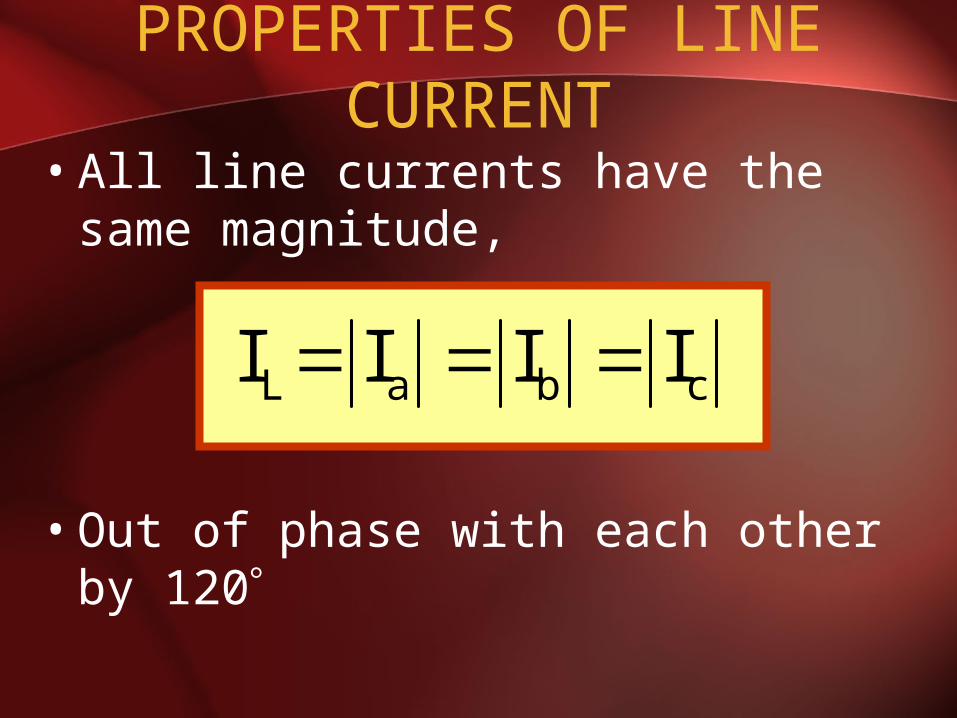
PROPERTIES OF LINE CURRENT
• All line currents have the same magnitude,
• Out of phase with each other by 120
cbaL IIII

1. Magnitude
2. Phase
- VL LAG their corresponding V by 30
FL II 3
RELATIONSHIP BETWEEN I and IL
30II FL

EXAMPLE
A balanced delta connected load having an impedance 20-j15 is connected to a delta connected, positive sequence generator having Vab = 3300 V. Calculate the phase currents of the load and the line currents.
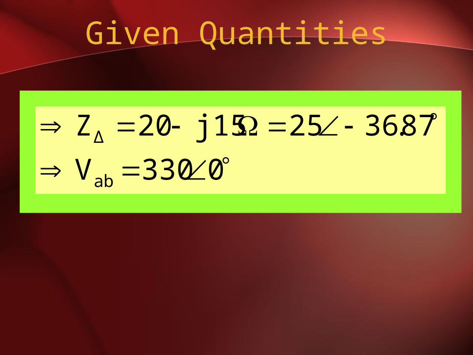
Given Quantities
0330V
87.3625 j1520Z
ab
Δ

Phase Currents
A87.15613.2120II
A13.83-13.2120II
A36.8713.238.8725
0330
Z
VI
ABCA
ABBC
Δ
ABAB

A87.12686.22120II
A13.311-86.22120II
87.686.22
A30336.8713.2
303II
ac
ab
ABa
Line Currents

BALANCED DELTA-WYE SYSTEM
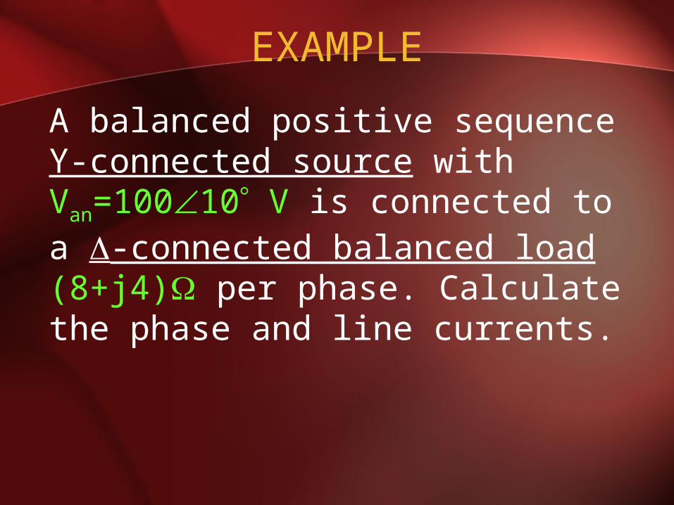
EXAMPLE
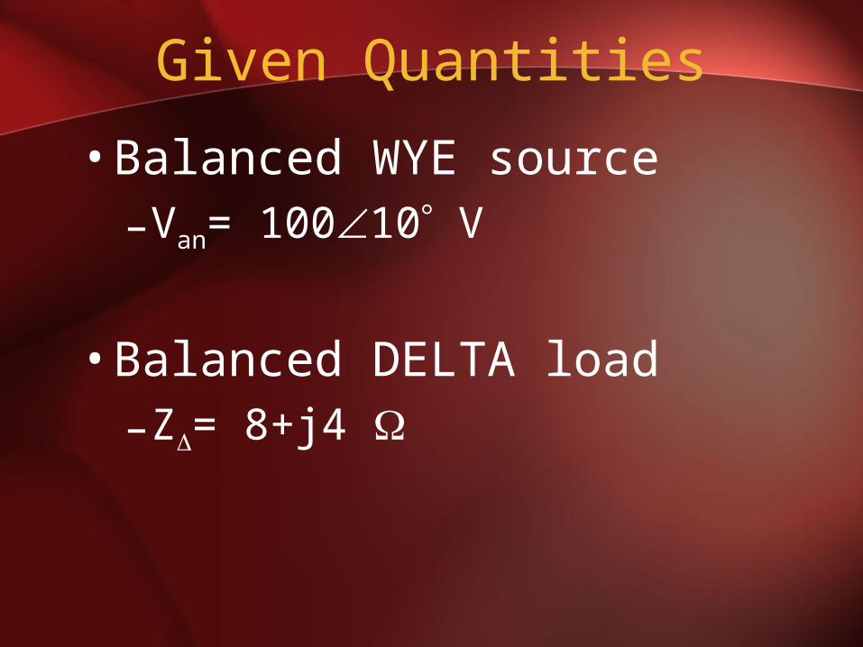
A balanced positive sequence Y-connected source with Van=10010 V is connected to a -connected balanced load (8+j4) per phase. Calculate the phase and line currents.
Given Quantities
•Balanced WYE source–Van= 10010 V
•Balanced DELTA load–Z= 8+j4
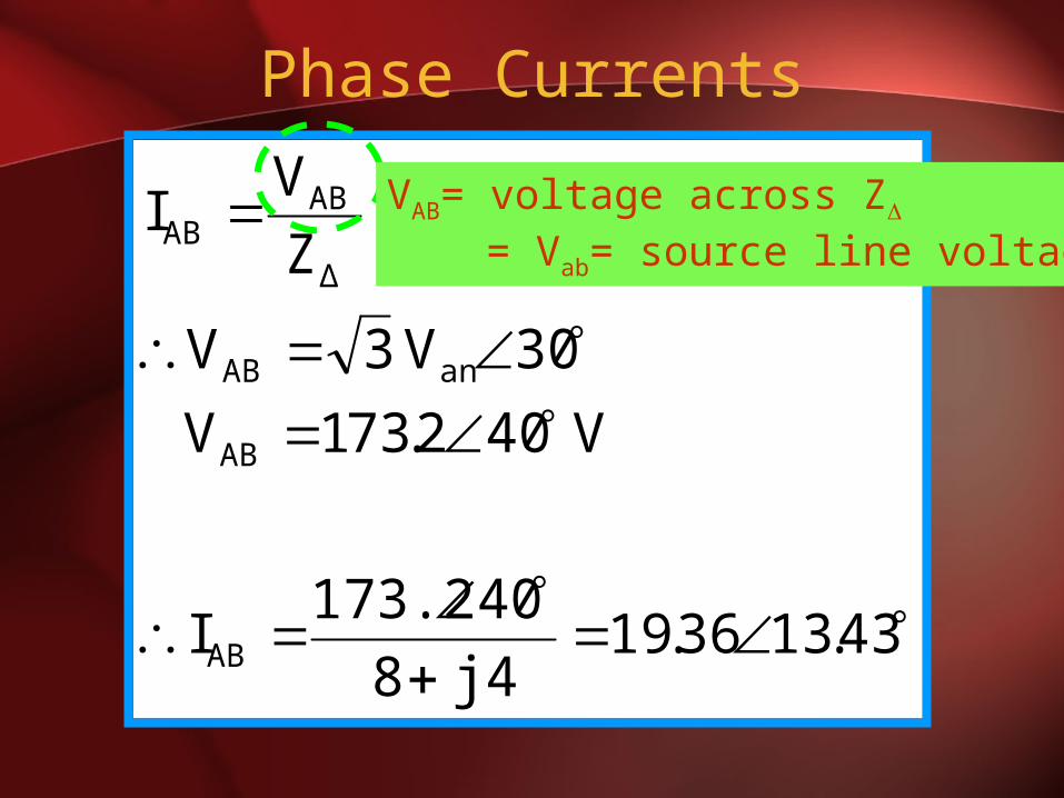
Phase Currents
43.1336.19j48
40173.2I
V 402.731V
30V 3V
Z
VI
AB
AB
anAB
Δ
ABAB
VAB= voltage across Z = Vab= source line voltage
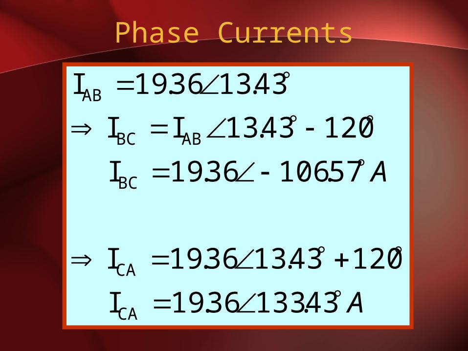
Phase Currents
A
A
43.13336.19I
12043.1336.19I
57.10636.19I
12043.13II
43.1336.19I
CA
CA
BC
ABBC
AB
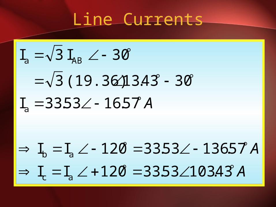
Line Currents
A
A
A
43.103 53.33120 II
57.136 53.33120 II
57.16 53.33I
3043.13 (19.36) 3
30 I 3I
ac
ab
a
ABa
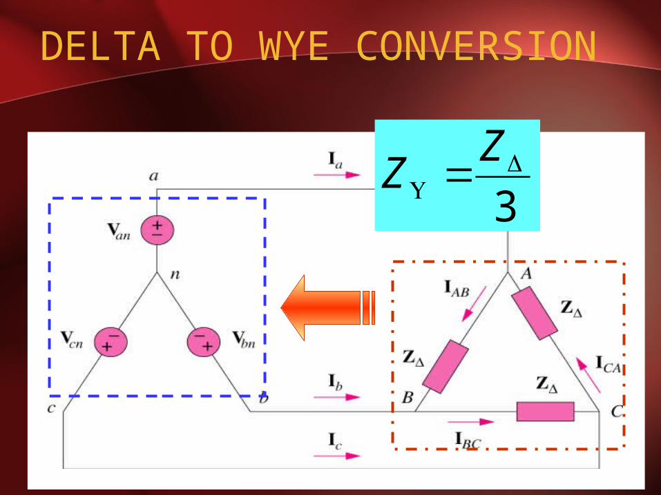
DELTA TO WYE CONVERSION
3
Z
Z

THREE PHASE POWER MEASUREMENT

FOUR WIRE SYSTEM• Each phase measured separately:
A
A
V
W
W
Phase A
Phase B
Phase C
VAN
IA
IC
V
A
V
W
IB
VBN
VCN
Neutral (N)
PA
PB
PC

THREE PHASE THREE WIRE SYSTEM
A
A
V
V
W
W
Phase A
Phase B
Phase C
VAB = VA - VB
VCB = VC - VB
IA
IC
PAB
PCBCBABT PPP
The three phase power is the sum of the two watt-meters reading
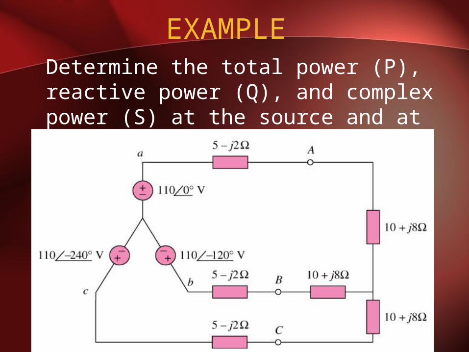
EXAMPLE Determine the total power (P), reactive power (Q), and complex power (S) at the source and at the load

Single Phase Equivalent Circuit
• Phase ‘a’ equivalent circuit
5-j2
810 j
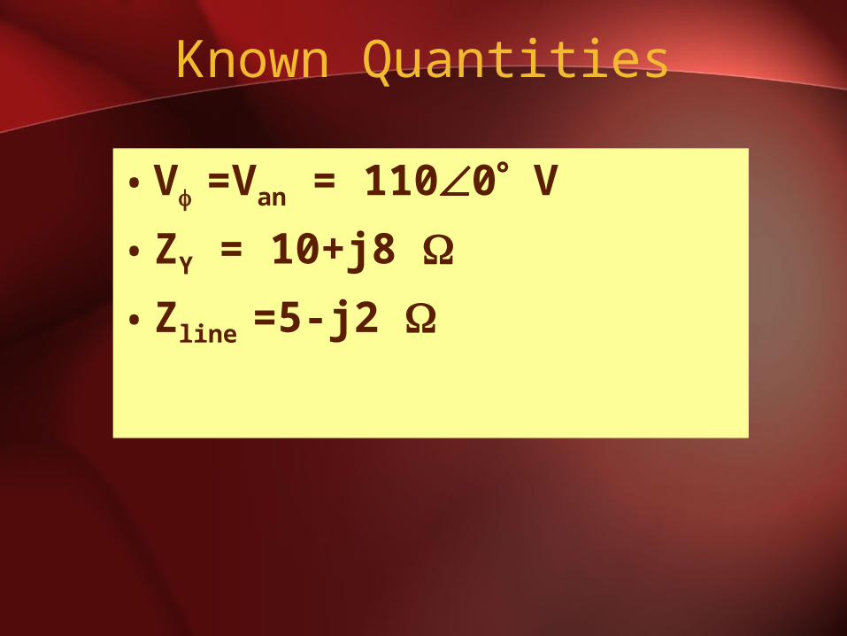
Known Quantities
•V =Van = 1100 V
•ZY = 10+j8
•Zline =5-j2
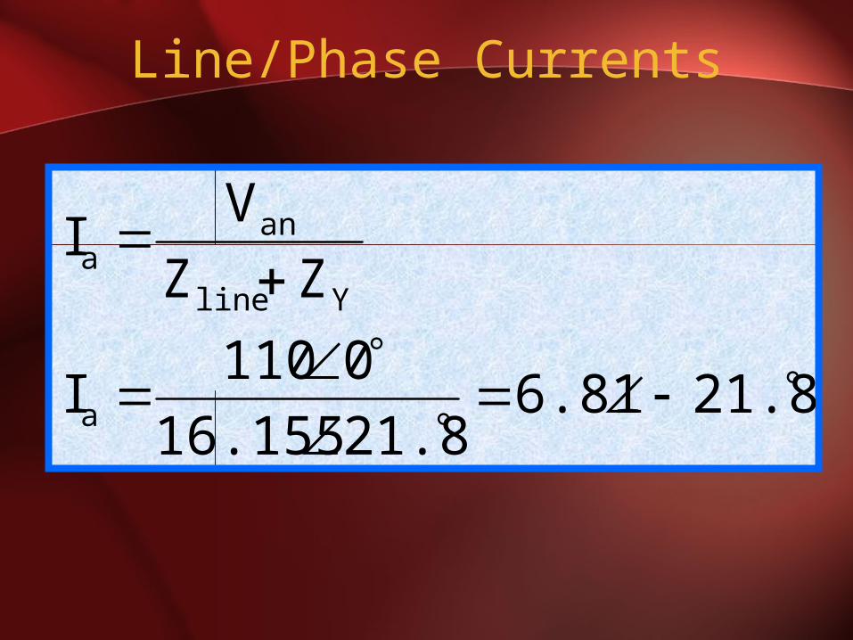
Line/Phase Currents
21.86.8121.816.155
0110I
ZZ
VI
a
Yline
ana
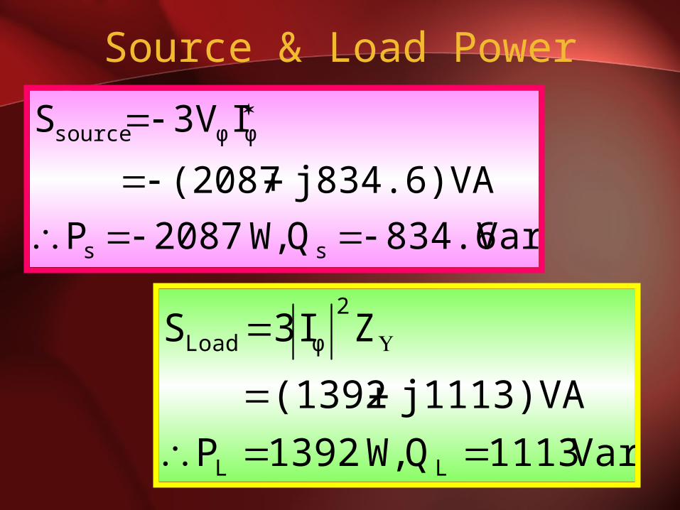
Source & Load Power
Var 834.6Q W,2087P
j834.6)VA(2087
I3VS
ss
φφsource
Var 1113Q W,1392P
j1113)VA(1392
ZI3S
LL
2
φLoad

EXAMPLE
A three phase motor can be regarded as a balanced Y-load. A three phase motor draws 5.6 kW when the line voltage is 220 V and the line current is 18.2 A. Determine the power factor of the motor

Known Quantities
• PLoad =5600 W
• VL = 220 V
• IL = 18.2 A
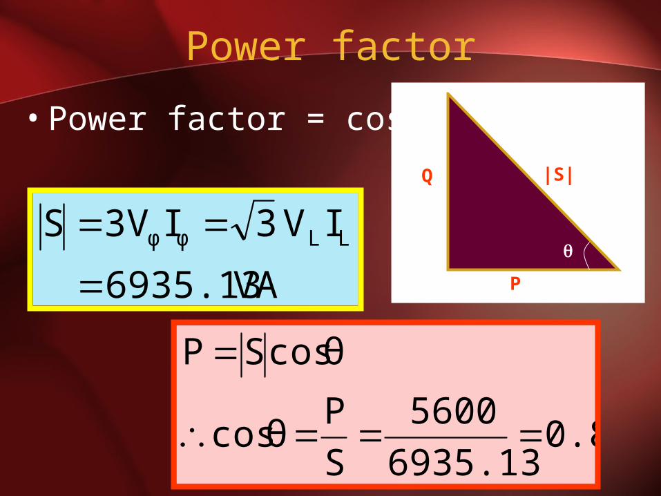
Power factor
• Power factor = cos
VA 6935.13
IV 3I3VS LLφφ
0.86935.13
5600
S
Pθ cos
θ cosSP
|S|Q
P