electrical system event - bangkok, thailand · electrical system event - bangkok, thailand 7...
TRANSCRIPT
ATSB TRANSPORT SAFETY INVESTIGATION REPORT Aviation Occurrence Investigation – AO-2008-003
Preliminary
Electrical system event - Bangkok, Thailand 7 January 2008
VH-OJM Boeing Company 747-438

ATSB TRANSPORT SAFETY INVESTIGATION REPORT Aviation Occurrence Investigation
AO-2008-003 Preliminary
Electrical system event - Bangkok, Thailand 7 January 2008
VH-OJM Boeing Company 747-438
Released in accordance with section 25 of the Transport Safety Investigation Act 2003
- i -

Published by: Australian Transport Safety Bureau Postal address: PO Box 967, Civic Square ACT 2608 Office location: 15 Mort Street, Canberra City, Australian Capital Territory Telephone: 1800 621 372; from overseas + 61 2 6274 6440 Accident and incident notification: 1800 011 034 (24 hours) Facsimile: 02 6247 3117; from overseas + 61 2 6247 3117 E-mail: [email protected] Internet: www.atsb.gov.au
© Commonwealth of Australia 2008.
This work is copyright. In the interests of enhancing the value of the information contained in this publication you may copy, download, display, print, reproduce and distribute this material in unaltered form (retaining this notice). However, copyright in the material obtained from other agencies, private individuals or organisations, belongs to those agencies, individuals or organisations. Where you want to use their material you will need to contact them directly.
Subject to the provisions of the Copyright Act 1968, you must not make any other use of the material in this publication unless you have the permission of the Australian Transport Safety Bureau.
Please direct requests for further information or authorisation to: Commonwealth Copyright Administration, Copyright Law Branch Attorney-General’s Department, Robert Garran Offices, National Circuit, Barton ACT 2600 www.ag.gov.au/cca
ISBN and formal report title: see ‘Document retrieval information’ on page iv.
- ii -
CONTENTS
THE AUSTRALIAN TRANSPORT SAFETY BUREAU .................................. v
GLOSSARY ........................................................................................................... vi
FACTUAL INFORMATION ................................................................................ 1 Initiation of investigation.................................................................................. 1 History of the flight........................................................................................... 1 Recorded aircraft data ....................................................................................... 3 Post flight inspection ........................................................................................ 3
Electrical System.................................................................................. 3 Water drainage system ......................................................................... 3
Other water accumulation events...................................................................... 4 Aircraft information .......................................................................................... 4
Forward galley waste water drainage system ....................................... 4 Aircraft electrical system...................................................................... 7 Main Equipment Centre ....................................................................... 8
Further investigation ......................................................................................... 9
SAFETY ACTIONS ............................................................................................. 11 Aircraft manufacturer...................................................................................... 11 Operator .......................................................................................................... 11
APPENDIX A : MEDIA RELEASE................................................................... 13
- iii -
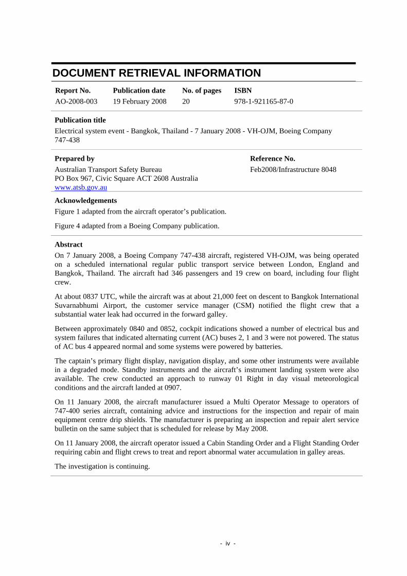
DOCUMENT RETRIEVAL INFORMATION Report No. AO-2008-003
Publication date 19 February 2008
No. of pages 20
ISBN 978-1-921165-87-0
Publication title Electrical system event - Bangkok, Thailand - 7 January 2008 - VH-OJM, Boeing Company 747-438
Prepared by Australian Transport Safety Bureau PO Box 967, Civic Square ACT 2608 Australia www.atsb.gov.au
Reference No. Feb2008/Infrastructure 8048
Acknowledgements Figure 1 adapted from the aircraft operator’s publication.
Figure 4 adapted from a Boeing Company publication.
Abstract On 7 January 2008, a Boeing Company 747-438 aircraft, registered VH-OJM, was being operated on a scheduled international regular public transport service between London, England and Bangkok, Thailand. The aircraft had 346 passengers and 19 crew on board, including four flight crew.
At about 0837 UTC, while the aircraft was at about 21,000 feet on descent to Bangkok International Suvarnabhumi Airport, the customer service manager (CSM) notified the flight crew that a substantial water leak had occurred in the forward galley.
Between approximately 0840 and 0852, cockpit indications showed a number of electrical bus and system failures that indicated alternating current (AC) buses 2, 1 and 3 were not powered. The status of AC bus 4 appeared normal and some systems were powered by batteries.
The captain’s primary flight display, navigation display, and some other instruments were available in a degraded mode. Standby instruments and the aircraft’s instrument landing system were also available. The crew conducted an approach to runway 01 Right in day visual meteorological conditions and the aircraft landed at 0907.
On 11 January 2008, the aircraft manufacturer issued a Multi Operator Message to operators of 747-400 series aircraft, containing advice and instructions for the inspection and repair of main equipment centre drip shields. The manufacturer is preparing an inspection and repair alert service bulletin on the same subject that is scheduled for release by May 2008.
On 11 January 2008, the aircraft operator issued a Cabin Standing Order and a Flight Standing Order requiring cabin and flight crews to treat and report abnormal water accumulation in galley areas.
The investigation is continuing.
- iv -

THE AUSTRALIAN TRANSPORT SAFETY BUREAU
The Australian Transport Safety Bureau (ATSB) is an operationally independent multi-modal bureau within the Australian Government Department of Infrastructure, Transport, Regional Development and Local Government. ATSB investigations are independent of regulatory, operator or other external organisations.
The ATSB is responsible for investigating accidents and other transport safety matters involving civil aviation, marine and rail operations in Australia that fall within Commonwealth jurisdiction, as well as participating in overseas investigations involving Australian registered aircraft and ships. A primary concern is the safety of commercial transport, with particular regard to fare-paying passenger operations.
The ATSB performs its functions in accordance with the provisions of the Transport Safety Investigation Act 2003 and Regulations and, where applicable, relevant international agreements.
Purpose of safety investigations
The object of a safety investigation is to enhance safety. To reduce safety-related risk, ATSB investigations determine and communicate the safety factors related to the transport safety matter being investigated.
It is not the object of an investigation to determine blame or liability. However, an investigation report must include factual material of sufficient weight to support the analysis and findings. At all times the ATSB endeavours to balance the use of material that could imply adverse comment with the need to properly explain what happened, and why, in a fair and unbiased manner.
Developing safety action
Central to the ATSB’s investigation of transport safety matters is the early identification of safety issues in the transport environment. The ATSB prefers to encourage the relevant organisation(s) to proactively initiate safety action rather than release formal recommendations. However, depending on the level of risk associated with a safety issue and the extent of corrective action undertaken by the relevant organisation, a recommendation may be issued either during or at the end of an investigation.
The ATSB has decided that when safety recommendations are issued, they will focus on clearly describing the safety issue of concern, rather than providing instructions or opinions on the method of corrective action. As with equivalent overseas organisations, the ATSB has no power to implement its recommendations. It is a matter for the body to which an ATSB recommendation is directed (for example the relevant regulator in consultation with industry) to assess the costs and benefits of any particular means of addressing a safety issue.
About ATSB investigation reports: How investigation reports are organised and definitions of terms used in ATSB reports, such as safety factor, contributing safety factor and safety issue, are provided on the ATSB web site www.atsb.gov.au.
- v -
GLOSSARY
AC Alternating Current
APB Auxiliary Power Breaker
APU Auxiliary Power Unit
BCU Bus Control Unit
BTB Bus Tie Breaker
CDU Control Display Unit
CSM Cabin Service Manager
DC Direct Current
DCIR Direct Current Isolation Relay
EICAS Engine Indicating and Crew Alerting System
EPR Engine Pressure Ratio
FDR Flight Data Recorder
FO First Officer
GCB Generator Circuit Breaker
GCU Generator Control Unit
ICAO International Civil Aviation Organisation
IDG Integrated Drive Generator
ILS Instrument Landing System
MEC Main Equipment Centre
ND Navigation Display
NNC Non-Normal Checklist
PFD Primary Flight Display
QAR Quick Access Recorder
SSB Split System Breaker
TRU Transformer Rectifier Unit
UTC Coordinated Universal Time
- vi -

FACTUAL INFORMATION The information contained in this preliminary report is derived from initial investigation of the occurrence. Readers are cautioned that there is the possibility that new evidence may come to light that alters the circumstances as depicted in this report.
Initiation of investigation On 7 January 2008, the Australian Transport Safety Bureau (ATSB) received notification that an electrical systems event had occurred on a Boeing Company 747-438 aircraft near Bangkok, Thailand. Initial reports suggested that the aircraft had sustained system failures resulting in the loss of all alternating current (AC) electrical power. On 9 January, the Department of Civil Aviation in Thailand delegated the conduct of the investigation to the ATSB in accordance with International Civil Aviation Organization (ICAO) Annex 13, paragraph 5.1.
History of the flight The Boeing Company 747-438 aircraft, registered VH-OJM, was being operated on a scheduled international regular public transport service between London, England and Bangkok, Thailand. The aircraft had 346 passengers and 19 crew on board, including four flight crew.
At about 0837 Coordinated Universal Time (UTC)1, while the aircraft was at about 21,000 feet on descent to Bangkok International Suvarnabhumi Airport, the customer service manager (CSM) notified the flight crew that a substantial water leak had occurred in the forward galley (Figure 1). The CSM later reported that the water was ‘smelly’ and that the water covered the entire galley floor. The CSM also reported that cabin crew had attempted to soak up the water using blankets, and that about four or five blankets were saturated.
Figure 1: Location of galley and main equipment centre
Forward galley Mid galley
Approximate location of drip shield Main equipment centre
1 All times are approximate and Bangkok local time was UTC +7 hours.
- 1 -
At 0840, the flight crew noticed a bus control unit (BCU) status message on a cockpit display. The message disappeared after a short period of time.
Between 0845 and 0852, cockpit indications showed a number of other electrical bus and system failures, including:
• alternating current (AC) bus 1, 2 and 3 not powered
• autothrottle disconnected automatically
• autopilot disengaged automatically
• right (first officer’s) displays blanked
• several pages of messages on the engine indicating and crew alerting system (EICAS)
• lower EICAS display blanked.
The status of AC bus 4 appeared normal. The flight crew reported main battery and auxiliary power unit (APU) battery discharge messages on the EICAS, indicating that some systems were being powered by batteries.
The flight crew reported that they actioned a number of non-normal checklists. After completion of the checklists, the EICAS and overhead panel annunciations indicated that the three of the four AC buses remained unpowered. The crew reported that they also checked the cockpit circuit breakers, and none of them appeared to be open.
The flight crew reported that the following instruments were available at this time:
• left (captain’s) primary flight display, in a degraded mode, but including attitude, airspeed, altitude, vertical speed and instrument landing system indications
• left navigation display, in a degraded mode
• left control display unit
• upper EICAS display, including landing gear indication
• standby instruments, comprising attitude indicator, airspeed, altitude, and compass
• right flap position indications.
In addition, the flight crew reported that:
• they communicated with air traffic control and noticed that the strength of the radio transmissions was less than normal
• Engine Pressure Ratio (EPR) was available only for the number-4 engine. The probe for the measurement of EPR on the number-4 engine was powered by AC bus 4.
The CSM reported that cabin lights had extinguished during the approach.
The crew conducted an approach to runway 01 Right in day visual meteorological conditions and the aircraft landed at 0907.
- 2 -

Recorded aircraft data The aircraft flight data recorder (FDR) and quick access recorder (QAR) data were obtained after the event. Both of these components were powered by AC Bus 3 and contained information about aircraft system behaviour prior to the loss of power to that bus. Preliminary analysis of the recorded data indicated the sequence of events in Table 1.
Table 1: Recorded sequence of events
Time Events
08:46:26 Bus Tie Breaker (BTB) 2 opened
08:46:29 Generator Circuit Breaker (GCB) 2 opened
AC Bus 2 unpowered
08:51:18 BTB 1 opened
GCB 1 opened
AC Bus 1 unpowered
08:51:26 BTB 3 opened
08:51:32 to 08:51:35
Loss of QAR data:
BTB 3 closed and
GCB 3 opened within this period
0852:33 FDR and QAR ceased operating
Post flight inspection
Electrical System The aircraft’s four generator control units (GCU) and two bus control units (BCU) were removed for testing. Water was reported to be present in the number-3 GCU, which controlled AC bus 3 circuit breakers. No water was reported to be present in any other electrical equipment.
Following the manufacturer’s recommendations, the number-2 engine Integrated Drive Generator (IDG) was also removed for testing.
Water drainage system Post-flight inspections identified a minor water leak in the forward galley sink drain, and that the first class galley ice drawer drain was blocked. Maintenance personnel reported the presence of water on the floor in the galley area after landing.
- 3 -

Maintenance personnel also identified cracks in a fibreglass drip shield2 located above an electrical component rack in the aircraft’s main equipment centre (MEC), as well as evidence of dark liquid stains on the shield.
Subsequent inspections found that a ribbon heater on a drain line leading to the forward grey water drain mast was inoperative, and that a length of drain line at that location was split. The heater and hose were removed for examination and testing.
The water boiler in the forward galley was removed for examination and testing.
Other water accumulation events During the flight preceding the incident flight, there was a water accumulation event on VH-OJM that resulted in maintenance action. The ATSB is seeking more information about this event.
The ATSB has received independent anecdotal reports of other water accumulation events on 747-400 aircraft.
Aircraft information
Forward galley waste water drainage system
The forward galley (Figure 2) drainage system consisted of sink drains and floor drains (Figure 3), each covered by a perforated grate. Waste water from galleys, galley drains, lavatory washbasins, and drinking fountains was directed overboard through drain masts (Figure 4). The drain masts were fitted with electrical ribbon heaters to prevent icing.
2 The drip shield is also known as the moisture shroud or drip tray.
- 4 -

Figure 2: Forward galley (example from VH-OJK)
Ice drawer
Sinks Waste bin lid
Cart bays
Forward
- 5 -

Figure 3: Floor drain in forward galley cart bay (example from VH-OJK)
Bench top
Floor drain
Forward
- 6 -

Figure 4: Forward drain mast and ribbon heater
Aircraft electrical system
The aircraft’s primary electrical system (Figure 5) comprised four AC buses and four associated direct current (DC) buses, each of which powered various items of aircraft electrical equipment.
A single IDG was fitted to each of the four aircraft engines and generated electrical power for the AC buses. Each IDG provided power to a separate AC bus via a generator circuit breaker (GCB). A bus tie breaker (BTB) on each bus enabled the buses to be tied or isolated, and a split system breaker (SSB) enabled the left side (1 and 2) buses to be tied to the right side (3 and 4).
There were four GCUs installed on the aircraft, each of which controlled the GCB and BTB for a particular AC bus. There were also two BCUs installed on the aircraft, which controlled the SSB.
- 7 -

There was an APU installed on the aircraft, which could provide auxiliary electrical power and bleed air to the aircraft systems. Two APU generators were installed, which could power the left and right side AC buses respectively via an APU breaker (APB). Each APU generator could provide the same amount of power as one IDG. The APU could only be started with the aircraft on the ground.
Each DC bus was driven from its respective AC bus via a transformer rectifier unit (TRU). The four DC buses were tied together via DC isolation relays (DCIR).
The aircraft also had a main battery bus and AC standby bus. The aircraft batteries could provide DC power for a limited period of time to the main battery bus depending on the equipment load demand. The main battery bus could also be powered from DC bus 3.
The AC standby bus could either be tied to AC bus 3 or powered by an inverter from the main battery bus, depending on cockpit switch selection.
Figure 5: Simplified electrical system schematic
Main Equipment Centre
The MEC (Figure 6) consisted of equipment racks which contained some of the electrical and avionic equipment on the aircraft, including the GCUs and BCUs. The MEC was located forward of and below, the forward galley (Figure 1). The drip shield was mounted above the MEC, and was designed to collect fluids such as condensation that would otherwise drip into the equipment racks from above, and to divert these fluids to drains on each side of the shield.
- 8 -

Figure 6: Main equipment centre (example from VH-OJK)
Repair
Drip shield
BCU 2
GCU 4 GCU 3 GCU 1 & 2, BCU 1
Forward
Further investigation The investigation is continuing and will include further examination and analysis of:
• FDR and QAR data
• the aircraft electrical generation, control and distribution system, including failure modes that could lead to multiple AC bus failures
• removed components, including four GCUs, two BCUs, number-2 IDG, galley water heater, and the drain mast ribbon heater
• sources of water including water drainage and supply systems during and prior to the incident flight
• water ingress path to the MEC and equipment
• potential water sources and ingress paths, including the incidence of water accumulation
• design and maintenance of water drainage, supply and ingress protection systems
• flight crew actions and operating procedures
• cabin crew operating procedures
• maintenance procedures.
- 9 -

- 10 -

SAFETY ACTIONS
Aircraft manufacturer On 11 January 2008, the aircraft manufacturer issued a Multi Operator Message to operators of 747-400 series aircraft that contained advice and instructions for the inspection and repair of main equipment centre drip shields.
The manufacturer is preparing an inspection and repair alert service bulletin on the same subject that is scheduled for release by May 2008.
Operator In response to the event the operator:
• Carried out a fleet inspection of 747-400 drip shields and made temporary repairs of any cracks found during those inspections. The operator identified cracks in the drip shields of 14 out of 30 aircraft inspected.
• Conducted a fleet inspection of 747-400 galleys to identify potential water leaks and drain blockages.
• Conducted a fleet inspection of 747-400 drain mast heaters, drain line heaters and drain mast hoses, and identified six failed drain ribbon heaters, two of which had associated split drain hoses.
On 11 January 2008, the aircraft operator issued a Cabin Standing Order to all 747-400 cabin crews, requiring them to identify, treat and report abnormal water accumulation in galley areas. On the same date the operator issued a Flight Standing Order advising 747-400 flight crews of this instruction.
- 11 -

- 12 -

APPENDIX A : MEDIA RELEASE ATSB Preliminary factual report on Boeing 747 electrical system event
An ATSB preliminary factual report into an electrical system failure involving a Boeing 747-400 near Bangkok on 7 January 2008 indicates that the event was less serious than first reported.
The aircraft, with 346 passengers and 19 crew on board, was being operated on a scheduled service between London and Bangkok. When the aircraft was at about 21,000 feet on descent to Bangkok Airport, the customer service manager notified the flight crew that a substantial water leak had occurred in the forward galley. Over the following 12 to 13 minutes, cockpit indications showed a number of electrical bus and system failures that indicated alternating current (AC) buses, 1, 2 and 3 were not powered. The status of AC bus 4 appeared normal and some systems were powered by batteries.
The captain’s primary flight display, navigation display, and some other instruments were available in a degraded mode and the crew conducted an uneventful approach and landing in day visual meteorological conditions.
Post-flight inspections identified a minor water leak in the forward galley sink drain and that an ice drawer drain was blocked. That inspection also found cracks in a fibreglass drip shield located above an electrical component rack in the aircraft’s main equipment centre, as well as evidence of dark liquid stains on the shield. Further inspection found that a ribbon heater on a drain line leading to the forward grey water drain mast was inoperative, and that a length of hose on the drain line at that location was split.
On 11 January 2008, the aircraft manufacturer issued a Multi Operator Message to operators of 747-400 series aircraft, containing advice and instructions for the inspection and repair of main equipment centre drip shields. The manufacturer is preparing an inspection and repair alert service bulletin on the same subject that is scheduled for release by May 2008.
In addition to conducting fleet-wide inspections and, where necessary, repairs to drip shields and drainage systems, the aircraft operator issued a Cabin Standing Order and a Flight Standing Order requiring cabin and flight crews to identify, treat and report abnormal water accumulation in galley areas.
The event involves complex systems and a wide-ranging investigation is continuing with the cooperation and assistance of local and international agencies, the aircraft manufacturer and the operator. Given the complex nature of the investigation, the ATSB is not able to comment further to the text contained in the preliminary report. Provision of analysis and findings in relation to the circumstances of this incident (which may be further revised) will be provided in the final report. In addition, the ATSB will immediately communicate any need for urgent safety action should that become evident during the investigation.
- 13 -