electrical science module 3 dc circuits - ntc sites textbooks/11... · electrical science dc...
TRANSCRIPT

DOE Fundamentals
ELECTRICAL SCIENCE
Module 3
DC Circuits

Electrical Science DC Circuits
i
TABLE OF CONTENTS
Table of Co nte nts TABLE OF CONTENTS ................................................................................................... i
LIST OF FIGURES ...........................................................................................................ii
LIST OF TABLES ............................................................................................................ iii
REFERENCES ................................................................................................................iv
OBJECTIVES .................................................................................................................. v
TERMINAL OBJECTIVE .............................................................................................. v
ENABLING OBJECTIVES ........................................................................................... v
INDUCTANCE ................................................................................................................. 1
Inductors ...................................................................................................................... 1
Summary ..................................................................................................................... 8
CAPACITANCE ............................................................................................................... 9
Capacitor ..................................................................................................................... 9
Capacitance ............................................................................................................... 11
Types of Capacitors ................................................................................................... 12
Capacitors in Series and Parallel ............................................................................... 13
Capacitive Time Constant .......................................................................................... 15
Summary ................................................................................................................... 17

Electrical Science DC Circuits
ii
LIST OF FIGURES
Figure 1 Induced EMF ........................................................................................... 1
Figure 2 Induced EMF in Coils ............................................................................... 2
Figure 3 Self-Induced EMF .................................................................................... 2
Figure 4 Inductors in Series ................................................................................... 3
Figure 5 Inductors in Parallel ................................................................................. 4
Figure 6 DC Current Through an Inductor ............................................................. 4
Figure 7 Time Constant ......................................................................................... 5
Figure 8 Voltage Applied to an Inductor ................................................................. 6
Figure 9 Inductor and Resistor in Parallel .............................................................. 7
Figure 10 Capacitor and Symbols ............................................................................ 9
Figure 11 Charging a Capacitor ............................................................................. 10
Figure 12 Discharging a Capacitor ......................................................................... 10
Figure 13 Capacitors Connected in Series ............................................................ 13
Figure 14 Capacitors Connected in Parallel ........................................................... 14
Figure 15 Example 1 - Capacitors Connected in Series ........................................ 15
Figure 16 Example 2 - Capacitors Connected in Series ........................................ 15
Figure 17 Example 3 - Capacitors Connected in Parallel ....................................... 16
Figure 18 Capacitive Time Constant for Charging Capacitor ................................. 17
Figure 19 Capacitive Time Constant for Discharging Capacitor ............................. 17
Figure 20 Example - Capacitive Time Constant ..................................................... 18
Electrical Science DC Circuits
iii
LIST OF TABLES
Table 1 Types of Capacitors ............................................................................... 13

Electrical Science DC Circuits
iv
REFERENCES
Gussow, Milton, Schaum's Outline of Basic Electricity, 2nd Edition, McGraw-Hill.
Academic Program for Nuclear Power Plant Personnel, Volume I & II, Columbia,
MD: General Physics Corporation, Library of Congress Card #A 326517, 1982.
Nasar and Unnewehr, Electromechanics and Electric Machines, 2nd Edition, John
Wiley and Sons.
Nooger and Neville Inc., Van Valkenburgh, Basic Electricity, Vol. 5, Hayden Book
Company.
Lister, Eugene C., Electric Circuits and Machines, 5th Edition, McGraw-Hill.
Croft, Hartwell, and Summers, American Electricians’ Handbook, 16th Edition,
McGraw-Hill.
Mileaf, Harry, Electricity One - Seven, Revised 2nd Edition, Prentice Hall.
Buban and Schmitt, Understanding Electricity and Electronics, 3rd Edition,
McGraw-Hill
Kidwell, Walter, Electrical Instruments and Measurements, McGraw-Hill.

Electrical Science DC Circuits
v
OBJECTIVES
TERMINAL OBJECTIVE
1.0 Using the rules associated with inductors and capacitors, DESCRIBE the
characteristics of these elements when they are placed in a DC circuit.
ENABLING OBJECTIVES
1.1 DESCRIBE how current flow, magnetic field, and stored energy in an inductor
relate to one another.
1.2 DESCRIBE how an inductor opposes a change in current flow.
1.3 Given a circuit containing inductors, CALCULATE total inductance for series and
parallel circuits.
1.4 Given an inductive resistive circuit, CALCULATE the time constant for the circuit.
1.5 DESCRIBE the construction of a capacitor.
1.6 DESCRIBE how a capacitor stores energy.
1.7 DESCRIBE how a capacitor opposes a change in voltage.
1.8 Given a circuit containing capacitors, CALCULATE total capacitance for series
and parallel circuits.
1.9 Given a circuit containing capacitors and resistors, CALCULATE the time
constant of the circuit.
Electrical Science Inductance
1
INDUCTANCE
Experiments investigating the unique behavioral characteristics of
inductance led to the invention of the transformer.
EO 1.1 DESCRIBE how current flow, magnetic field, and stored
energy in an inductor relate to one another.
EO 1.2 DESCRIBE how an inductor opposes a change in current
flow.
EO 1.3 Given a circuit containing inductors, CALCULATE total
inductance for series and parallel circuits.
EO 1.4 Given an inductive resistive circuit, CALCULATE the time
constant for the circuit.
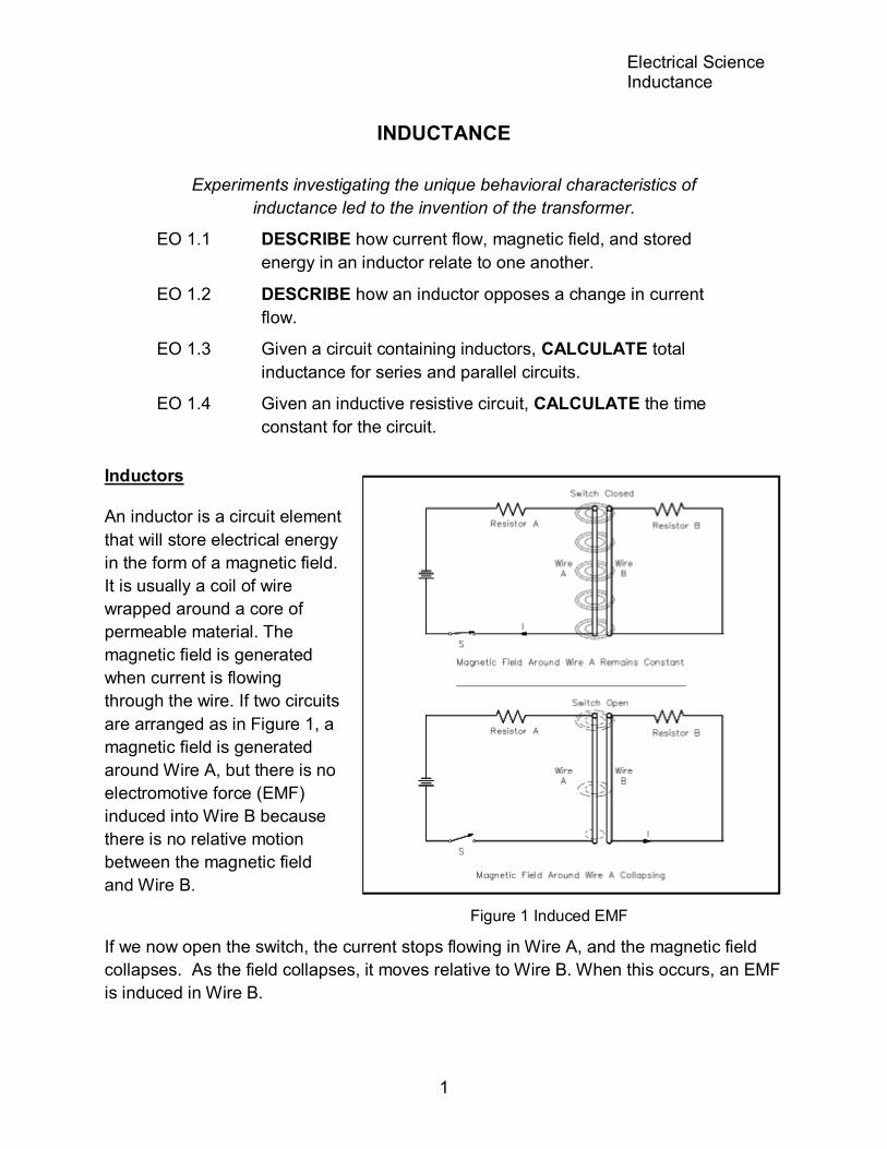
Inductors
An inductor is a circuit element
that will store electrical energy
in the form of a magnetic field.
It is usually a coil of wire
wrapped around a core of
permeable material. The
magnetic field is generated
when current is flowing
through the wire. If two circuits
are arranged as in Figure 1, a
magnetic field is generated
around Wire A, but there is no
electromotive force (EMF)
induced into Wire B because
there is no relative motion
between the magnetic field
and Wire B.
Figure 1 Induced EMF
If we now open the switch, the current stops flowing in Wire A, and the magnetic field
collapses. As the field collapses, it moves relative to Wire B. When this occurs, an EMF
is induced in Wire B.

Electrical Science Inductance
2
This is an example of Faraday's Law, which states that a voltage is induced in a
conductor when that conductor is moved through a magnetic field, or when the
magnetic field moves past the conductor. When the EMF is induced in Wire B, a current
will flow whose magnetic field opposes the change in the magnetic field that produced it.
For this reason, an induced EMF is sometimes called counter EMF or CEMF. This is an
example of Lenz's Law, which states that the induced EMF opposes the EMF that
caused it.
The three requirements for
inducing an EMF are:
1. a conductor,
2. a magnetic field, and
3. relative motion between the
two.
The faster the conductor moves,
or the faster the magnetic field
collapses or expands, the greater
the induced EMF. The induction
can also be increased by coiling the
wire in either Circuit A or Circuit B,
or both, as shown in Figure 2.
Self-induced EMF is another
phenomenon of induction. The
circuit shown in Figure 3 contains a
coil of wire called an inductor (L).
As current flows through the circuit,
a large magnetic field is set up
around the coil. Since the current is
not changing, there is no EMF
produced. If we open the switch,
the field around the inductor
collapses. This collapsing magnetic field produces a voltage in the coil. This is called
self-induced EMF.
The polarity of self-induced EMF is given to us by Lenz's Law. The polarity is in the
direction that opposes the change in the magnetic field that induced the EMF. The result
is that the current caused by the induced EMF tends to maintain the same current that
existed in the circuit before the switch was opened. It is commonly said that an inductor
tends to oppose a change in current flow.

Electrical Science Inductance
3
The induced EMF, or counter EMF, is proportional to the time rate of change of the
current. The proportionality constant is called the "inductance" (L). Inductance is a
measure of an inductor's ability to induce CEMF. It is measured in henries (H). An
inductor has an inductance of one henry if one amp per second change in current
produces one volt of CEMF, as shown in Equation (3-1).
CEMF = -L ΔI Δt
(3-1)
where
CEMF = induced voltage (volts)
L = inductance (henries)
ΔI / Δt = time rate of change of current (amp/sec)
The minus sign shows that the CEMF is opposite in polarity to the applied voltage.
Example: A 4-henry inductor is in series with a variable resistor. The resistance is
increased so that the current drops from 6 amps to 2 amps in 2 seconds. What is the
CEMF induced?
CEMF = -L ΔI Δt
= -4 2A - 6A 2
= -4 (-2)
CMEF =+8 volts
Inductors in series are combined
like resistors in series.
Equivalent inductance (Leq) of
two inductors in series (Figure 4)
is given by Equation (3-2).
Figure 4 Inductors in Series Leq = L1 + L2 + ... Ln (3-2)
Electrical Science Inductance
4
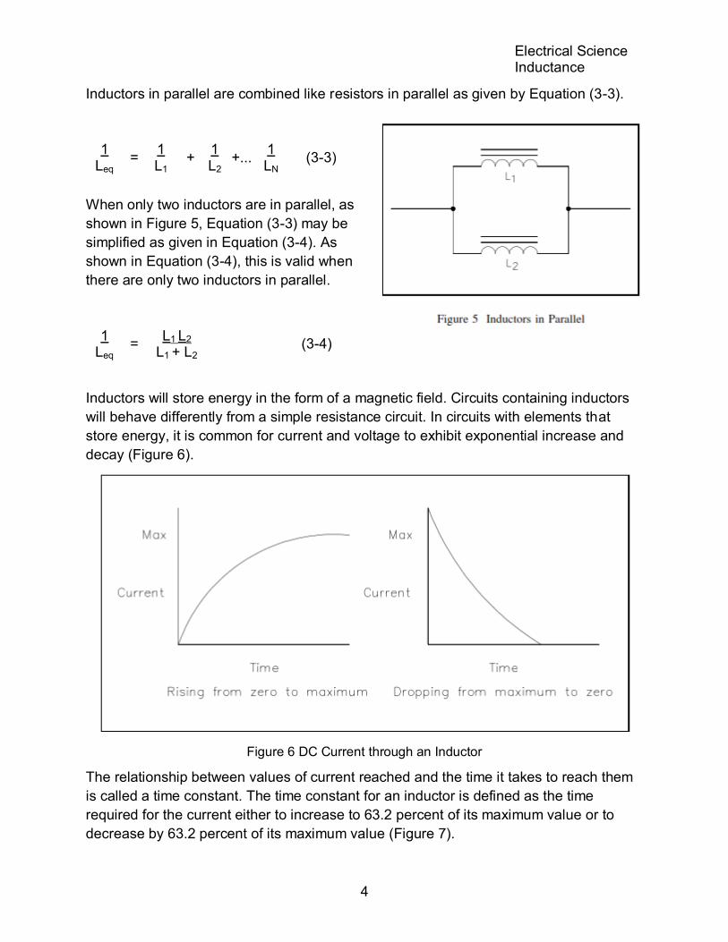
Inductors in parallel are combined like resistors in parallel as given by Equation (3-3).
1 Leq
= 1 L1
+ 1 L2
+... 1 LN
(3-3)
When only two inductors are in parallel, as
shown in Figure 5, Equation (3-3) may be
simplified as given in Equation (3-4). As
shown in Equation (3-4), this is valid when
there are only two inductors in parallel.
1 Leq
= L1 L2
L1 + L2 (3-4)
Inductors will store energy in the form of a magnetic field. Circuits containing inductors
will behave differently from a simple resistance circuit. In circuits with elements that
store energy, it is common for current and voltage to exhibit exponential increase and
decay (Figure 6).
Figure 6 DC Current through an Inductor
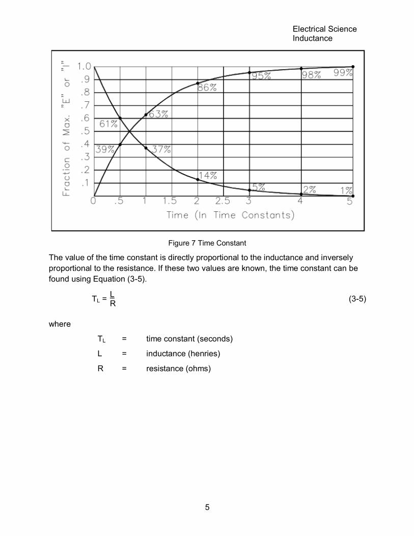
The relationship between values of current reached and the time it takes to reach them
is called a time constant. The time constant for an inductor is defined as the time
required for the current either to increase to 63.2 percent of its maximum value or to
decrease by 63.2 percent of its maximum value (Figure 7).
Electrical Science Inductance
5
Figure 7 Time Constant
The value of the time constant is directly proportional to the inductance and inversely
proportional to the resistance. If these two values are known, the time constant can be
found using Equation (3-5).
TL = L R
(3-5)
where
TL = time constant (seconds)
L = inductance (henries)
R = resistance (ohms)

Electrical Science Inductance
6
The voltage drop across an inductor is directly proportional to the product of the
inductance and the time rate of change of current through the inductor, as shown in
Equation (3-6).
VL = L ΔI Δt
(3-6)
where
VL = voltage drop across the inductor (volts)
L = inductance (henries)
ΔI / Δt = time rate of change of current (amp/sec)
After five time constants, circuit parameters normally reach their final value. Circuits that
contain both inductors and resistors are called RL circuits. The following example will
illustrate how an RL circuit reacts to changes in the circuit (Figure 8).
1. Initially, the switch is in Position 1,
and no current flows through the
inductor.
2. When we move the switch to
Position 2, the battery attempts to
force a current of 10v/100n = 0.1A
through the inductor. But as current
begins to flow, the inductor
generates a magnetic field. As the
field increases, a counter EMF is
induced that opposes the battery
voltage. As a steady state is
reached, the counter EMF goes to
zero exponentially.
3. When the switch is returned to
Position 1, the magnetic field
collapses, inducing an EMF that
tends to maintain current flow in the
same direction through the inductor.
Its polarity will be opposite to that
induced when the switch was placed
in Position 2.
Figure 8 Voltage Applied to an Inductor
Electrical Science Inductance
7
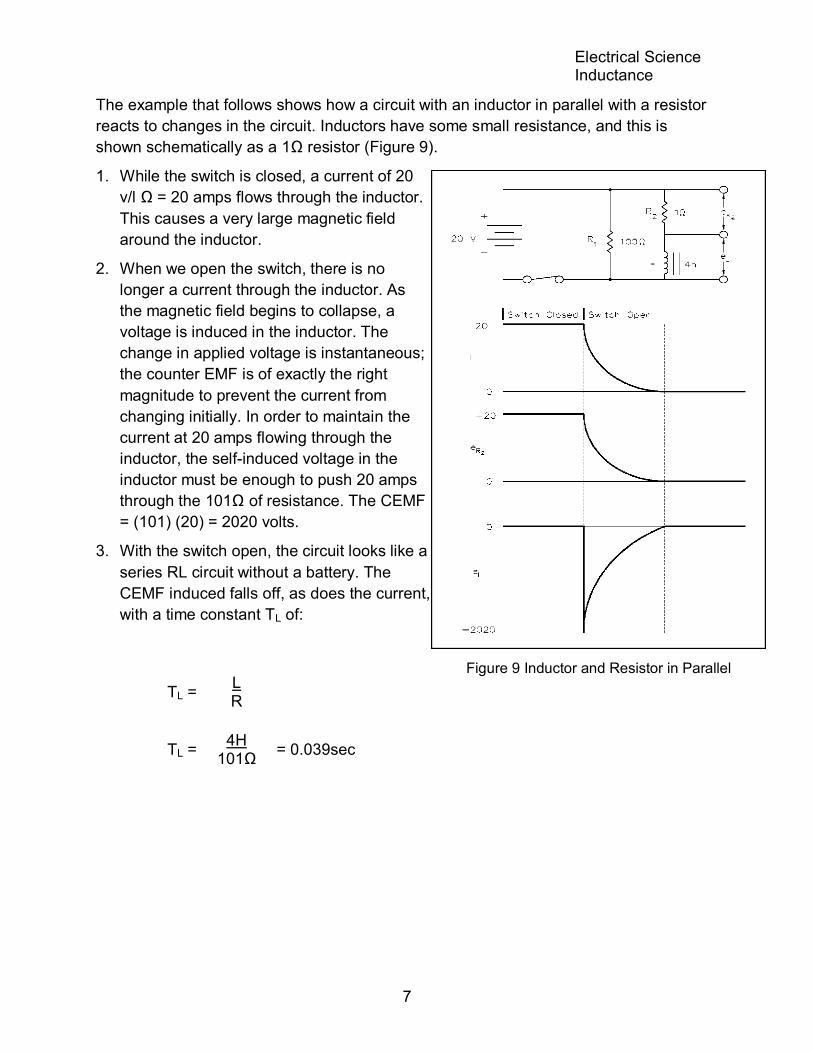
Figure 9 Inductor and Resistor in Parallel
The example that follows shows how a circuit with an inductor in parallel with a resistor
reacts to changes in the circuit. Inductors have some small resistance, and this is
shown schematically as a 1Ω resistor (Figure 9).
1. While the switch is closed, a current of 20
v/l Ω = 20 amps flows through the inductor.
This causes a very large magnetic field
around the inductor.
2. When we open the switch, there is no
longer a current through the inductor. As
the magnetic field begins to collapse, a
voltage is induced in the inductor. The
change in applied voltage is instantaneous;
the counter EMF is of exactly the right
magnitude to prevent the current from
changing initially. In order to maintain the
current at 20 amps flowing through the
inductor, the self-induced voltage in the
inductor must be enough to push 20 amps
through the 101Ω of resistance. The CEMF
= (101) (20) = 2020 volts.
3. With the switch open, the circuit looks like a
series RL circuit without a battery. The
CEMF induced falls off, as does the current,
with a time constant TL of:
TL = L R
TL = 4H
101Ω = 0.039sec
Electrical Science Inductance
8
Summary
The important information on inductors is summarized below.
Inductance Summary
When an inductor has a DC current flowing through it, the inductor will store
energy in the form of a magnetic field.
An inductor will oppose a change in current flow by the CEMF induced when
the field collapses or expands.
Inductors in series are combined like resistors in series.
Inductors in parallel are combined like resistors in parallel.
The time constant for an inductor is defined as the required time for the current
either to increase to 63.2 percent of its maximum value or to decrease by 63.2
percent of its maximum value.
Electrical Science Capacitance
9
CAPACITANCE
Because of the effect of capacitance, an electrical circuit can store energy,
even after being de-energized.
EO 1.5 DESCRIBE the construction of a capacitor.
EO 1.6 DESCRIBE how a capacitor stores energy.
EO 1.7 DESCRIBE how a capacitor opposes a change in voltage.
EO 1.8 Given a circuit containing capacitors, CALCULATE total capacitance for
series and parallel circuits.
EO 1.9 Given a circuit containing capacitors and resistors, CALCULATE the time
constant of the circuit.
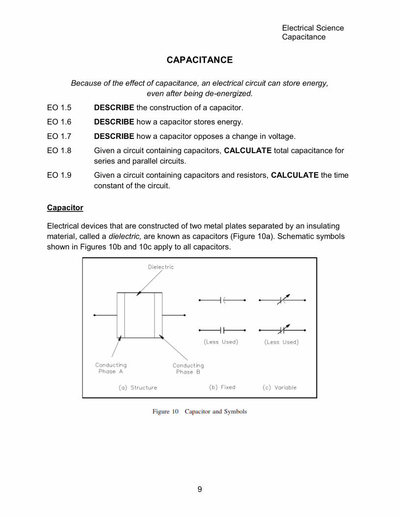
Capacitor
Electrical devices that are constructed of two metal plates separated by an insulating
material, called a dielectric, are known as capacitors (Figure 10a). Schematic symbols
shown in Figures 10b and 10c apply to all capacitors.

Electrical Science Capacitance
10
Figure 12 Discharging a Capacitor
The two conductor plates of the capacitor, shown in Figure 11 a, are electrically neutral,
because there are as many positive as negative charges on each plate. The capacitor,
therefore, has no charge.
Now, we connect a
battery across the plates
(Figure 11b). When the
switch is closed (Figure
11c), the negative
charges on Plate
A are attracted to the
positive side of the
battery, while the positive
charges on Plate B are
attracted to the negative
side of the battery. This
movement of charges will
continue until the difference in charge between Plate A and Plate B is equal to the
voltage of the battery. This is now a "charged capacitor." Capacitors store energy as an
electric field between the two plates.
Because very few of the charges
can cross between the plates, the
capacitor will remain in the charged
state even if the battery is
removed. Because the charges on
the opposing plates are attracted
by one another, they will tend to
oppose any changes in charge. In
this manner, a capacitor will
oppose any change in voltage felt
across it.
If we place a conductor across the
plates, electrons will find a path
back to Plate A, and the charges
will be neutralized again. This is
now a "discharged" capacitor
(Figure 12).

Electrical Science Capacitance
11
Capacitance
Capacitance is the ability to store an electrical charge. Capacitance is equal to the
amount of charge that can be stored divided by the applied voltage, as shown in
Equation (3-7).
C = Q / V (3-7)
where
C = capacitance (F)
Q = amount of charge (C)
V = voltage (V)
The unit of capacitance is the farad (F). A farad is the capacitance that will store one
coulomb of charge when one volt is applied across the plates of the capacitor.
The dielectric constant (K) describes the ability of the dielectric to store electrical
energy. Air is used as a reference and is given a dielectric constant of 1. Therefore, the
dielectric constant is unitless. Some other dielectric materials are paper, teflon, bakelite,
mica, and ceramic.
The capacitance of a capacitor depends on three things.
1. Area of conductor plates
2. Separation between the plates
3. Dielectric constant of insulation material
Equation (3-8) illustrates the formula to find the capacitance of a capacitor with two
parallel plates.
C = K A d
(8.85x10⁻¹²) (3-8)
where
C = capacitance
K = dielectric constant
A = area
d = distance between the plates
8.85 x 10-12 = constant of proportionality

Electrical Science Capacitance
12
Example 1: Find the capacitance of a capacitor that stores 8C of charge at 4V.
C = Q / V
C = 8 / 4
C = 2F
Example 2: What is the charge taken on by a 5F capacitor at 2 volts?
Q = C V
Q = (5F) (2V)
Q= 10C
Example 3: What is the capacitance if the area of a two plate mica capacitor is 0.0050
m2 and the separation between the plates is 0.04 m? The dielectric
constant for mica is 7.
C = K A d
(8.85x10⁻¹²)
C = 7 0.0050
0.04 (8.85x10⁻¹²)
= 7.74x10⁻¹²F
= 7.74ρF
Types of Capacitors
All commercial capacitors are named according to their dielectrics. The most common
are air, mica, paper, and ceramic capacitors, plus the electrolytic type. These types of
capacitors are compared in Table 1.
TABLE 1
Types of Capacitors
Dielectric Construction Capacitance Range
Air Meshed plates 10 - 400ρF
Mica Stacked Sheets 10 - 5000ρF
Paper Rolled foil 0.001 - 1μF
Ceramic Tubular 0.5 - 1600ρF
Disk Tubular 0.002 - 0.1μF
Electrolytic Aluminum 5 - 1000μF
Tantalum Aluminum 0.01 - 300μF
Electrical Science Capacitance
13
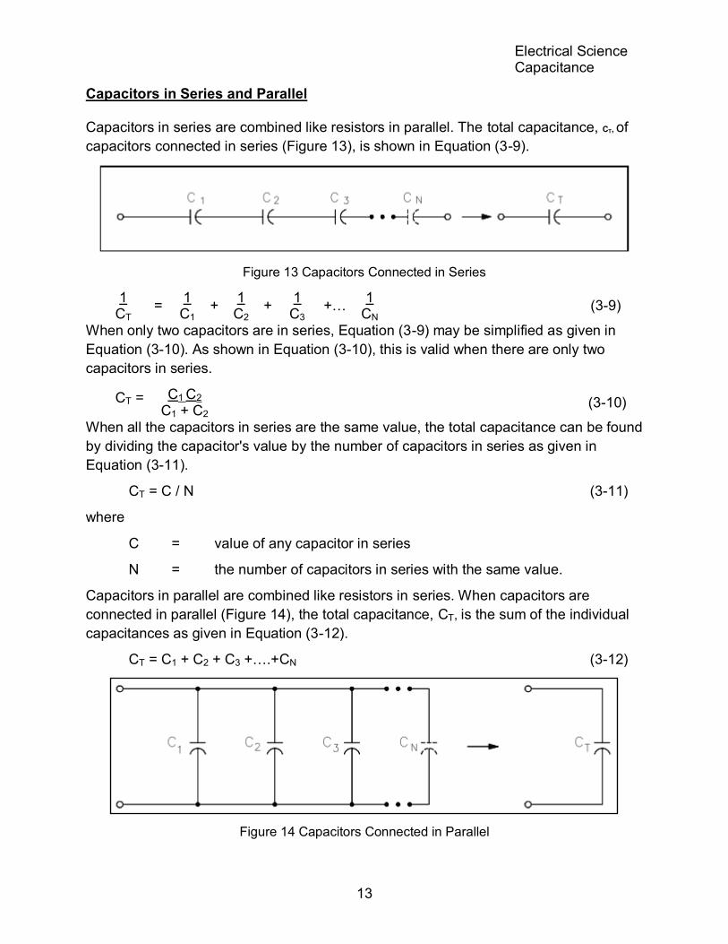
Capacitors in Series and Parallel
Capacitors in series are combined like resistors in parallel. The total capacitance, CT, of
capacitors connected in series (Figure 13), is shown in Equation (3-9).
Figure 13 Capacitors Connected in Series
1 CT
= 1 C1
+ 1 C2
+ 1
C3 +…
1 CN
(3-9)
When only two capacitors are in series, Equation (3-9) may be simplified as given in
Equation (3-10). As shown in Equation (3-10), this is valid when there are only two
capacitors in series.
CT = C1 C2 C1 + C2
(3-10)
When all the capacitors in series are the same value, the total capacitance can be found
by dividing the capacitor's value by the number of capacitors in series as given in
Equation (3-11).
CT = C / N (3-11)
where
C = value of any capacitor in series
N = the number of capacitors in series with the same value.
Capacitors in parallel are combined like resistors in series. When capacitors are
connected in parallel (Figure 14), the total capacitance, CT, is the sum of the individual
capacitances as given in Equation (3-12).
CT = C1 + C2 + C3 +….+CN (3-12)
Figure 14 Capacitors Connected in Parallel

Electrical Science Capacitance
14
Example 1: Find the total capacitance of 3µF, 6µF, and 12µF capacitors connected in
series (Figure 15).
Example 2: Find the total capacitance and working voltage of two capacitors in series,
when both have a value of 150 µF, 120 V (Figure 16).

Electrical Science Capacitance
15
Example 3: Find the total capacitance of three capacitors in parallel, if the values are
15 µF-50 V, 10 µF-100 V, and 3 µF-150 V (Figure 17). What would be the
working voltage?
Capacitive Time Constant
When a capacitor is connected to a DC voltage source, it charges very rapidly. If no
resistance was present in the charging circuit, the capacitor would become charged
almost instantaneously. Resistance in a circuit will cause a delay in the time for
charging a capacitor. The exact time required to charge a capacitor depends on the
resistance (R) and the capacitance (C) in the charging circuit. Equation (3-13) illustrates
this relationship.
Tc = R C (3-13)
where:
Tc = capacitive time constant (sec)
R = resistance (ohms)
C = capacitance (farad)
The capacitive time constant is the time required for the capacitor to charge to 63.2
percent of its fully charged voltage. In the following time constants, the capacitor will
charge an additional 63.2 percent of the remaining voltage. The capacitor is considered
fully charged after a period of five time constants (Figure 18).

Electrical Science Capacitance
16
Figure 18 Capacitive Time Constant for Charging Capacitor
The capacitive time constant also shows that it requires five time constants for the
voltage across a discharging capacitor to drop to its minimum value (Figure 19).
Figure 19 Capacitive Time Constant for Discharging Capacitor

Electrical Science Capacitance
17
Example: Find the time constant of a 100μF capacitor in series with a 100Ω resistor
(Figure 20).
Figure 20 Example - Capacitive Time Constant
Summary
The important information on capacitors is summarized below.
Capacitance Summary
A capacitor is constructed of two conductors (plates) separated by a dielectric.
A capacitor will store energy in the form of an electric field caused by the
attraction of the positively-charged particles in one plate to the negatively-
charged particles in the other plate.
The attraction of charges in the opposite plates of a capacitor opposes a
change in voltage across the capacitor.
Capacitors in series are combined like resistors in parallel.
Capacitors in parallel are combined like resistors in series.
The capacitive time constant is the time required for the capacitor to charge
(or discharge) to 63.2 percent of its fully charged voltage.