electrical & refrigeration engineering foundations building a...electrical & refrigeration...
TRANSCRIPT

Electrical & Refrigeration Engineering Electricity, Electronics, HVAC and Refrigeration
Aberdeen High School Course Syllabus First Year Students
Developed by
Chuck Veloni © 2014 [email protected]
Packet 7 – Building a Refrigeration System
1.) Book Work
a.) HVC3.1 _____/2 b.) HVC3.2 _____/2
c.) HVC3.3 _____/1
2.) Videos
3.) Labs a.) Run Tubing & Evacuation _____/10
b.) Wiring Condenser, Pump Down, Evap _____/5
c.) Charging System _____/3 d.) Setting an LPC _____/4
e.) Reclaim & Recovery _____/2
f.) Reflection _____/1
Total for Packet 7 30 pts _____

Beginning Mechanical
Related Bookwork & Worksheets:
Copland Refrigeration Manual Part 2 Read pages 4-1 through 11-4
Copland Refrigeration Manual Part 4
Read pages 17-1 through 18-2
HVAC Level Three Training Guide (NCCER) ISBN #0-13-614387-3
Read pages 1.1 through 1.29, do questions 1 through 15 on pages 1.30 Read pages 2.1 through 2.41, do questions 1 through 15 on pages 2.42 & 2.43 Read pages 3.1 through 3.22, do questions 1 through 10 on pages 3.23 & 3.24


Industrial Engineering Electricity, Electronics, HVAC and Refrigeration
High School Course Developed by
Chuck Veloni © 2013 [email protected]
Beginning Mechanical
Lab: Building a Refrigeration System – pt. 1
Running Tubing & Evacuation of your System Lab 10 pts
“…Plan your work, work your plan” – Dale Benner Grays Harbor PUD Lineman
Objective: To be able build the refrigeration system as per a set of drawings and to evacuate your system to hold a perfect vacuum. Overview: Students will run the suction and liquid lines for their refrigeration system. The runs will follow the design that the student laid out in the previous lab. Students will also pump down their system to hold a perfect vacuum using their gauges and a vacuum pump.
Tools: Tubing Benders, Tubing Cutters, Torches, Swaging Tools, Flaring Tools & Blocks, Solder, Vacuum Pump, Misc. Tools from your Tools Box, Hammer, Teflon Tape Safety: You will be working with sharp tools. Flying Copper shards also present a hazard. You will be working with explosive gasses. You will also be working with an open flame, be very careful where you are pointing the end of the torch. The torch will create very hot areas so be careful what you touch, you could get burned. REMOVE ANY LIGHTERS FROM YOUR POCKETS, THESE CAN EXPLODE!!!! Make sure that you always light the acetylene first, then temper in the oxygen. When turning off the torch, turn off the oxygen first, then the acetylene. When you are done with the torch you will need to turn off the tanks at the valve and then bleed the lines. Do not work in a confined area, gasses can over-come you. Work in a well ventilated area. When you are finished, make sure the tanks are put away in the fire cabinet. YOU WILL WEAR SAFETY GLASSES AT ALL TIMES!!!
Diagram: Use the diagram provided
Procedures: First you will take your condensing unit and place it on top of the cooler box. Starting with your suction line, lay out your run from the suction service valve all the way to the outlet port of your evaporator. You will use Teflon tape on the suction service valve and where the suction line meets the outlet port of the evaporator. Next you will run your liquid line from your condensing unit to the solenoid valve with the arrow pointing towards the expansion valve. From there you will attach solenoid valve to the expansion valve located at your evaporator. DO NOT FORGET TO INSTALL A SIGHT GLASS AFTER THE FILTER/DRIER AS CLOSE TO THE RECIEVER AS POSSIBLE. These runs must match your drawing. Do not forget to braze/solder heat exchanger. Then you need to mount the thermostat on the side of your cooler box. Finally, attach the bulb from your expansion valve to the suction line that is coming out of your evaporator and going to your compressor. You will attach this with a copper strap. AT

THIS POINT, HAVE THE INSTRUCTOR INSPECT YOUR WORK! Next you will take your gauges and hook up the suction side hose (blue hose) to the suction service valve (located on the back of the condensing unit, larger of the two). Then take the high pressure hose (red hose) and hook it to the liquid line service valve (located towards the front of the condensing unit, on the receiver, the smaller of the two). Then take the charging/evacuation line (yellow line) and hook that up to the vacuum pump. Turn on vacuum pump. Open up the gauges and the service valves. Allow system to pump down to 29.92 inches of vacuum. Close off gauges, then turn off vacuum pump. Allow time for system to hold vacuum (apprx. 10-15 minutes). If the unit does not hold a vacuum then check for leaks starting with your flare connections and then your brazeing/soldering joints. Fix any leaks and re-evacuate. AT THIS POINT, HAVE THE INSTRUCTOR INSPECT YOUR WORK AGAIN!
Restate the procedures in your own words:
__________________________________________________________________________________________________________________________________________________
__________________________________________________________________________________________________________________________________________________
___________________________________________
__________________________________________________________________________________________________________________________________________________
__________________________________________________________________________________________________________________________
Student Notes:
Instructor’s Signature & Date:
Competencies:
H.S Math Standards – A.1.1.A, A1.1.B, A.1.6.B, G.3.C, G.3.D, G.3.E, College Readiness Math Standards – 1.1, 1.2, 1.3, 3.1, 5.4
Science – 9-12 SYSA, 9-12 SYSC, 9-12 SYSD, 9-12 INQB, 9-12 INQC, 9-12 APPD, 9-11 PSIA,
9-11 PSID, 9-11 PSIE, 9-11 PSIG, 9-11 PS2G, 9-11 PS2K, 9-11 PS3A, 9-11 PS3B, 9-11 PS3D, 9-11 PS3E,
Reading – 1.2.2, 1.3.2, 3.3.1
Writing – 1.1.1, 1.3.1, 1.6.3, 2.3.1, 3.3.1, 3.3.3
AHRI – 710 2004, 715 2007, 740 1998, 750 2007, 900 2004
Applicable NEC Codes – 210, 210.52, 210.63, 210.70, 240, 240.4,
440, 440.3, 440.14, 500.5, 500.6, 505.5, 550.12, 626, 626.30, 701, 701.2, 702, 702.2, A, C, O, R

Industrial Engineering Electricity, Electronics, HVAC and Refrigeration
High School Course Developed by
Chuck Veloni © 2013 [email protected]
Beginning Mechanical
Lab: Building a Refrigeration System – pt. 2
Wiring the Condensing Unit, LPC, Pump Down System & Evaporator Lab 5 pts
Objective: To correctly wire up the condensing unit and evaporator for proper operation. Overview: Students, using a 14/3 S/O cord, will wire up their condensing unit and their evaporator. Students will make all connection in a 4X4 junction box. Tools: Screw Drivers, Pliers, VOM Meter, Wire Strippers, Safety: You will work with vessels that may contain high pressure gases. You will be working with live voltage. You can get shocked if you act in a careless manner. Do not put power to your project until the instructor has inspected it first. YOU WILL WEAR SAFETY GLASSES AT ALL TIMES!!!
Procedures: First, you will mount a 4X4 junction box to your condensing unit. Then you will take your cord cap that you made in a previous lab and attach it to the 4X4 junction box. You will then run an S/O cord down from the 4X4 junction box that you just installed to the junction box on the side of the evaporator. You will mount the low pressure control switch to the front of the condensing unit. Next you will run the cap tube of the LPC to the suction-line service valve. You will then run a 14/2 SO cord from the LPC to the junction box on the side of the condensing unit. This will be connected with romex fittings. The power source wire, the evaporator wire and the black wire running to the LPC will be connected together. The white wire coming from the LPC, the condenser fan wire and the wire that goes to the 3-in-1 kit will be connected together. Next you will manually pump your system down into a vacuum. You will then take two short pieces of 14/3 S/O cord and hook one end up to the junction box located on the side of the evaporator. The other side of the short piece will be attached to the thermostat. With the second piece you will attach one end to the junction box and one end to the solenoid valve. You will hook up the black wire going to the thermostat to the hot wire going to the evaporator. At the thermostat you will hook up the black wire to one terminal and the white wire to the other terminal. You will also need to place a black piece of tape around the white wire to indicate that it is a hot wire. Back in the junction box you will place another black piece of tape around the white wire that you just attached in the thermostat. With that wire you will attach it to the black wire that is hooked up to the solenoid valve. The white wire that is coming from the solenoid will need to be attached to the neutral wires going to the evaporator. At the solenoid, hook up the black and white wires to the two wires coming from the coil (it does not matter which one goes where). AT THIS POINT, HAVE THE INSTRUCTOR INSPECT YOUR WORK!
Restate the procedures in your own words: _________________________________________________________________________
_________________________________________________________________________

_________________________________________________________________________
____________________________________________________________________________________________________________________
______________________________________________________________________________________________________________________________________
Diagram:
3-in-1 KitCompressor
Hot/H
Neutral/N
120VAC
Condenser Fan Motor
Evaporator Fan Motor
Red/Run
Black/Common
White/Start
N
H
H
H
N
N
LPC
Thermostat Solenoid
Coil
Student Notes:
Instructor’s Signature & Dates:

Competencies:
H.S Math Standards – A.1.1.A, A1.1.B, A.1.2.A, A.1.2.F, A.1.3.B, A.1.4.A, A.2.1.E,
College Readiness Math Standards – 1.1, 1.2, 1.3, 3.1, 3.2,
Science – 9-12 SYSA, 9-12 SYSC, 9-12 SYSD, 9-12 INQB, 9-12 INQC, 9-12 APPD, 9-11 PSIA,
9-11 PSID, 9-11 PSIE, 9-11 PSIG, 9-11 PS2G, 9-11 PS2K, 9-11 PS3A, 9-11 PS3B, 9-11 PS3D, 9-11 PS3E,
Reading – 1.2.2, 1.3.2, 3.3.1
Writing – 1.1.1, 1.3.1, 1.6.3, 2.3.1, 3.3.1
AHRI – 130 1988, 710 2004, 715 2007, 750 2007, 900 2004
Applicable NEC Codes – 210, 210.52, 210.63, 210.70, 240, 240.4, 440, 440.3, 440.14, 500.5, 500.6, 505.5, 550.12, 626, 626.30, 701, 701.2, 702, 702.2, A, C, O, R

Industrial Engineering Electricity, Electronics, HVAC and Refrigeration
High School Course Developed by
Chuck Veloni © 2013 [email protected]
Beginning Mechanical
Lab: Building a Refrigeration System – pt. 3
Charging (3 pts for charging your system + 2 pts for teaching someone how to charge their system)
Lab 3 pts
Objective: To correctly charge a refrigeration system that has a thermal expansion valve Overview: Students will charge their system with refrigerant to demonstrate. Tools: Screw Drivers, gauges, valve wrenches, VOM Safety: You will work with vessels that may contain high pressure gases. You will be working with live voltage. You can get shocked if you act in a careless manner. Do not put power to your project until the instructor has inspected it first. YOU WILL WEAR SAFETY GLASSES AT ALL TIMES!!!
Procedures: First (assuming that you kept the gauges attached) make sure that the system is still in a vacuum; If not then re-evacuate the system and find the leak. After that you will hook up the charging/evacuation hose (yellow) to the refrigerant tank. You will then turn on the tank and turn it upside-down. You will then “purge” the charging/evacuation hose by loosening the yellow hose to let any air out of the hose. Be sure to do this in a quick manner as not to let any refrigerant out. AT THIS POINT, HAVE THE INSTRUCTOR INSPECT YOUR WORK! You will then open up the high-side gauge valve (red) to allow refrigerant to flow into the system. Watch the suction side gauge, when the pressure reads approximately 20-25 psi. At this point close off your high-side gauge and turn on your system. You will then meter in refrigerant into the suction side (blue) until the sight glass is approximately 85% full.
Restate the procedures in your own words: _________________________________________________________________________
__________________________________________________________________________________________________________________________________________________
_________________________________________________________________________
___________________________________________
Diagram:

Make sure system is in a vacuum. Disconnect Charging/Evacuation hose (yellow) from the
gauges.
Attach Charging/Evacuation hose to the refrigerant tank.

Open up valve on the tank and turn the tank upside down.
Purge the charging hose
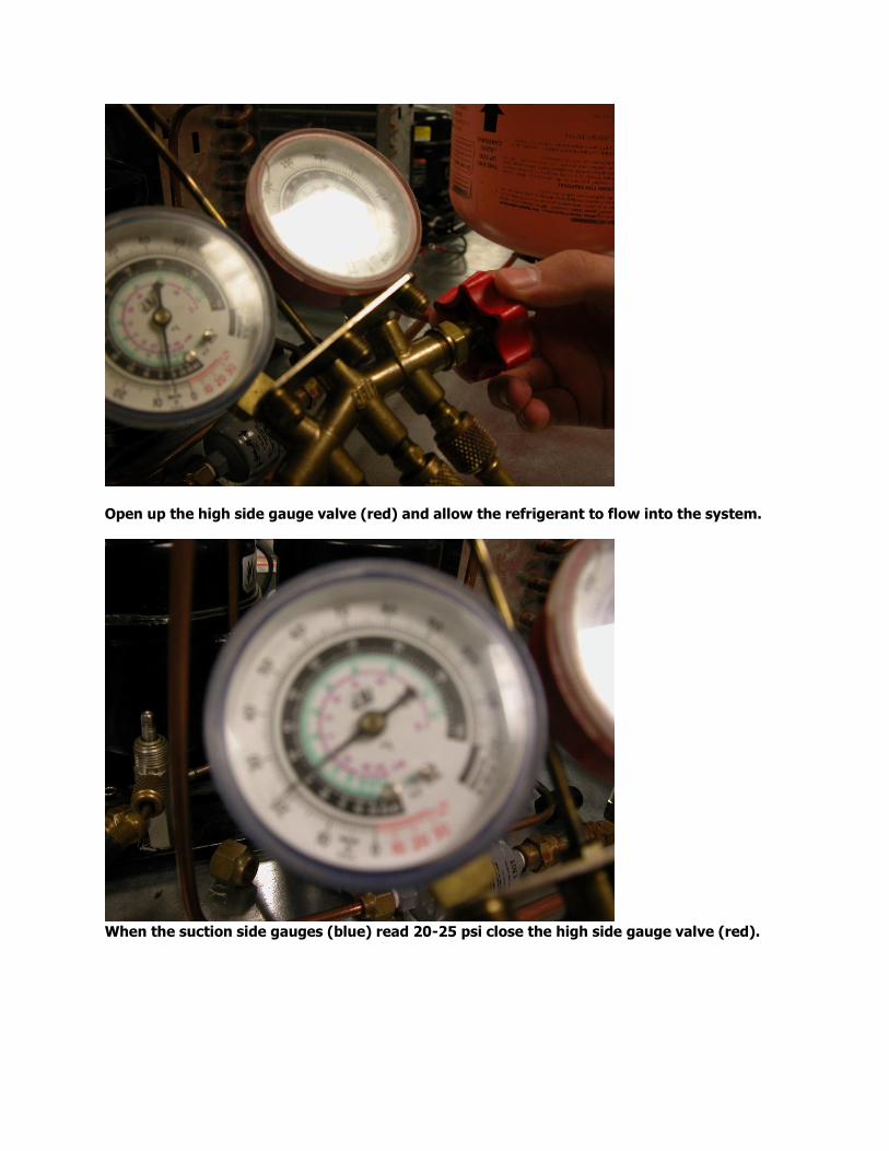
Open up the high side gauge valve (red) and allow the refrigerant to flow into the system.
When the suction side gauges (blue) read 20-25 psi close the high side gauge valve (red).
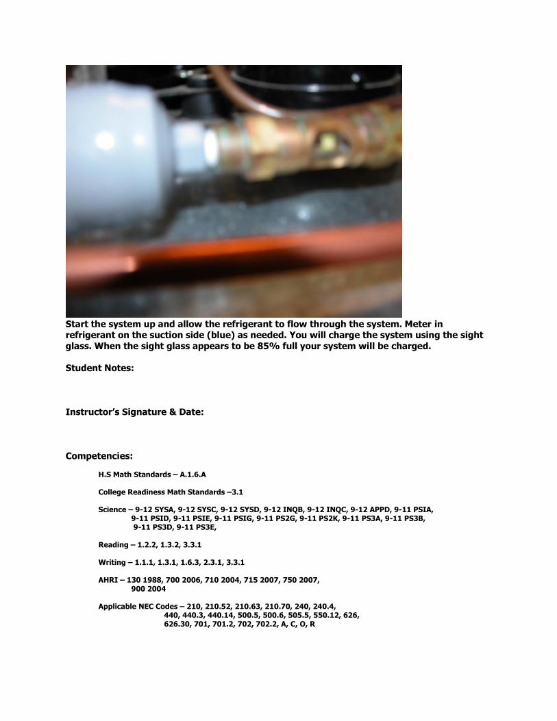
Start the system up and allow the refrigerant to flow through the system. Meter in refrigerant on the suction side (blue) as needed. You will charge the system using the sight
glass. When the sight glass appears to be 85% full your system will be charged.
Student Notes:
Instructor’s Signature & Date:
Competencies:
H.S Math Standards – A.1.6.A College Readiness Math Standards –3.1
Science – 9-12 SYSA, 9-12 SYSC, 9-12 SYSD, 9-12 INQB, 9-12 INQC, 9-12 APPD, 9-11 PSIA,
9-11 PSID, 9-11 PSIE, 9-11 PSIG, 9-11 PS2G, 9-11 PS2K, 9-11 PS3A, 9-11 PS3B, 9-11 PS3D, 9-11 PS3E,
Reading – 1.2.2, 1.3.2, 3.3.1
Writing – 1.1.1, 1.3.1, 1.6.3, 2.3.1, 3.3.1
AHRI – 130 1988, 700 2006, 710 2004, 715 2007, 750 2007, 900 2004
Applicable NEC Codes – 210, 210.52, 210.63, 210.70, 240, 240.4,
440, 440.3, 440.14, 500.5, 500.6, 505.5, 550.12, 626, 626.30, 701, 701.2, 702, 702.2, A, C, O, R

Industrial Engineering Electricity, Electronics, HVAC and Refrigeration
High School Course Developed by
Chuck Veloni © 2013 [email protected]
Beginning Mechanical
Lab: Building a Refrigeration System – pt. 4
Installing a Low-Pressure Control Switch & Calibrating a Low-Pressure Control Switch Lab 4 pts
Objective: To set a Low-Pressure Control Switch and maintain two different temperatures based off of pressure. Overview: Students will maintain different temperatures based off of pressure readings. Tools: Screw Drivers, gauges, valve wrenches, crescent wrenches, Pressure-Temperature chart Safety: You will work with vessels that may contain high pressure gases. You will be working with live voltage. You can get shocked if you act in a careless manner. Do not put power to your project until the instructor has inspected it first. YOU WILL WEAR SAFETY GLASSES AT ALL TIMES!!!
Related Bookwork:
None
Procedures: The main thing that you need to know is that there is a 10 degree temperature differential between the boiling point of the refrigerant in your evaporator and the box temperature of the system. With that in mind, all calibrations need to involve this in part of the equation. The equation is; Cut-Out equals Cut-In minus Differential or C.O. = C.I. – Diff. Example; If you wanted to maintain a 50 degree box using Refrigerant R-416A you will need to know a few things. First, how to read a pressure-temperature chart, the far left column reads Fahrenheit degrees. The rest of the columns are different refrigerants and their corresponding boiling points to the temperature in Fahrenheit degrees in the far left column. For R-416A there are two columns. The first column is the corresponding temperature of R-416A in a liquid state to its pressure. The one that you want to focus in on is the “vapor” column. This is the Pressure/Temperature relation as it’s “boiling off” or “evaporating.” Here’s an example of how to go about setting a LPC; See example on next page EXAMPLE
Desired Box Temp 50 *F

Differential between Boiling point of refrigerant & desired box temperature - 10 *F The temperature that the Refrigerant needs to boils at 40 *F Pressure of R-416A at this temp * This is the pressure that you want To maintain on an average basis 40 *F (R-416A)= 26.8psig The first thing to set on your LPC is the differential. Normally The differential is set between 15 psig & 20 psig. You need to Divide the value of the differential By two and add it to the desired 26.8 psig Pressure. 20 psig / 2 = +10 psig This is where you need to set your Cut-In pressure 36.8 psig The formula C.O. = C.I. – Diff 16.8 psig = 36.8 psig - 20 psig The desired pressure is right in The middle. 26.8 psig After you have figured out the math you will need to identify the two adjusting screws on the LPC. On a Penn LPC, the adjusting screws are located on the top of the control. The differential adjusting screw is setting on the left while the cut-in adjusting screw is setting off to the right. REMEMBER the LPC dial is merely getting you close; you will need to set your LPC based off of your gauge readings.
USE PRESSURE TEMPERATURE CHART PREVIOUSLY HANDED OUT
Restate the procedures in your own words: _________________________________________________________________________
__________________________________________________________________________________________________________________________________________________
____________________________________________________________________________________________________________________
Mount the LPC in front of the Condensing Unit

First adjust the differential screw to your desired setting
After calculating the math, adjust your cut-in screw to your desired setting.
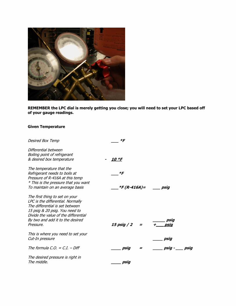
REMEMBER the LPC dial is merely getting you close; you will need to set your LPC based off of your gauge readings.
Given Temperature
Desired Box Temp ___ *F Differential between Boiling point of refrigerant & desired box temperature - 10 *F The temperature that the Refrigerant needs to boils at ___*F Pressure of R-416A at this temp * This is the pressure that you want To maintain on an average basis ___*F (R-416A)= ___ psig The first thing to set on your LPC is the differential. Normally The differential is set between 15 psig & 20 psig. You need to Divide the value of the differential By two and add it to the desired _____ psig Pressure. 15 psig / 2 = +___ psig This is where you need to set your Cut-In pressure ____ psig The formula C.O. = C.I. – Diff ____ psig = ____ psig - ___ psig The desired pressure is right in The middle. ____ psig

Student Notes:
Instructor’s Signature & Date:
Competencies:
H.S Math Standards – A.1.1.A, A1.1.B, A.1.2.A, A.1.2.F, A.1.3.B, A.1.4.A, A.2.1.E
College Readiness Math Standards – 1.1, 1.2, 1.3, 3.1, 3.2,
Science – 9-12 SYSA, 9-12 SYSC, 9-12 SYSD, 9-12 INQB, 9-12 INQC, 9-12 APPD, 9-11 PSIA,
9-11 PSID, 9-11 PSIE, 9-11 PSIG, 9-11 PS2G, 9-11 PS2K, 9-11 PS3A, 9-11 PS3B, 9-11 PS3D, 9-11 PS3E,
Reading – 1.2.2, 1.3.2, 3.3.1
Writing – 1.1.1, 1.3.1, 1.6.3, 2.3.1, 3.3.1
AHRI – 130 1988, 700 2006, 710 2004, 715 2007, 750 2007, 900 2004
Applicable NEC Codes – 210, 210.52, 210.63, 210.70, 240, 240.4,
440, 440.3, 440.14, 500.5, 500.6, 505.5, 550.12, 626, 626.30, 701, 701.2, 702, 702.2, A, C, O, R

Industrial Engineering Electricity, Electronics, HVAC and Refrigeration
High School Course Developed by
Chuck Veloni © 2013 [email protected]
Beginning Mechanical
Lab: Building a Refrigeration System – pt. 5
Reclaim and Recovery of Refrigerant
Labs 2 pts
Objective: To recover/reclaim the refrigerant that is currently in your system via an approved recovery system and placed into authorized recovery tanks. Overview: Students will remove the refrigerant from their system and place it into recovery tanks.
Tools: Screw Drivers, gauges, valve wrenches, crescent wrenches, recovery system, recovery tanks
Safety: You will work with vessels that may contain high pressure gases. You will be working with live voltage. You can get shocked if you act in a careless manner. Do not put power to your project until the instructor has inspected it first. YOU WILL WEAR SAFETY GLASSES AT ALL TIMES!!!
Procedures: First you will disconnect power to your system. Then you will take the charging/evacuation hose (the yellow one) and attach it to inlet port of the recovery system. Make sure that your high side (red) and low side (blue) are properly attached. You will then take another yellow hose and hook it up to the outlet port of the recovery system. The other end of the hose that is attached to the outlet port will then need to be hooked up to a recovery tank that is labeled with the same type of refrigerant as the refrigerant that you are using in your tank (ie:416-A, 134A, etc.) AT THIS POINT, HAVE THE INSTRUCTOR INSPECT YOUR WORK! You will then open both the high side and low side gauge valves. You will purge any aire out of the lines at the following places; 1.) leading into the recovery system and leading into the recovery tank. Only after you have purged the lines of air should you open the valves of the system, then repeat this process for the tank. Once all of the valves have been opened start the recovery system. The recovery system will operate until then system is in a vacuum. The system will shut itself off. Allow a little time for the system pressure to rise up a bit and then restart the recovery system. Close off all valves, turn off the power to the recovery system and disconnect your hoses. AT THIS POINT, HAVE THE INSTRUCTOR RE-INSPECT YOUR WORK!
Restate the procedures in your own words:
__________________________________________________________________________________________________________________________________________________
_________________________________________________________________________

_________________________________________________________________________
___________________________________________
Student Notes:
Instructor’s Signature & Date:
Competencies:
H.S Math Standards – N/A College Readiness Math Standards – N/A
Science – 9-12 SYSA, 9-12 SYSC, 9-12 SYSD, 9-12 INQB, 9-12 INQC, 9-12 APPD, 9-11 PSIA,
9-11 PSID, 9-11 PSIE, 9-11 PSIG, 9-11 PS2G, 9-11 PS2K, 9-11 PS3A, 9-11 PS3B, 9-11 PS3D, 9-11 PS3E,
Reading – 1.2.2, 1.3.2, 3.3.1
Writing – 1.1.1, 1.3.1, 1.6.3, 2.3.1, 3.3.1
AHRI – 130 1988, 700 2006, 710 2004, 715 2007, 740 1998, 750 2007, 900 2004
Applicable NEC Codes – 210, 210.52, 210.63, 210.70, 240, 240.4,
440, 440.3, 440.14, 500.5, 500.6, 505.5, 550.12, 626, 626.30, 701, 701.2, 702, 702.2, A, C, O, R
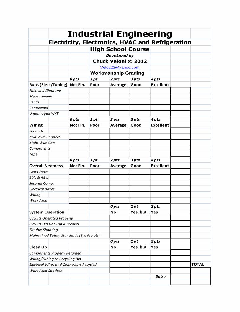
Industrial EngineeringElectricity, Electronics, HVAC and Refrigeration
High School CourseDeveloped by
Chuck Veloni © 2012
Workmanship Grading
0 pts 1 pt 2 pts 3 pts 4 pts
Runs (Elect/Tubing) Not Fin. Poor Average Good Excellent
Followed Diagrams
Measurements
Bends
Connectors
Undamaged W/T
0 pts 1 pt 2 pts 3 pts 4 pts
Wiring Not Fin. Poor Average Good Excellent
Grounds
Two-Wire Connect.
Multi-Wire Con.
Components
Tape
0 pts 1 pt 2 pts 3 pts 4 pts
Overall Neatness Not Fin. Poor Average Good Excellent
First Glance
90's & 45's
Secured Comp.
Electrical Boxes
Wiring
Work Area
0 pts 1 pt 2 pts
System Operation No Yes, but… Yes
Circuits Operated Properly
Circuits Did Not Trip A Breaker
Trouble Shooting
Maintained Safety Standards (Eye Pro etc)
0 pts 1 pt 2 pts
Clean Up No Yes, but… Yes
Components Properly Returned
Wiring/Tubing to Recycling Bin
Electrical Wires and Connectors Recycled TOTAL
Work Area Spotless
Sub >
