electrical optimization and simulation of your pcb...
TRANSCRIPT
© Copyright CADCAM Group 2015
Steve Gascoigne
Senior Consultant at Mentor Graphics
Zagreb, 10. lipnja 2015.
Electrical optimization and simulation of your
PCB design

2 © Copyright CADCAM Group 2015
The Challenge of Validating a Design..

3 © Copyright CADCAM Group 2015
A Complete Analysis Solution
Address multiple design
areas through virtual
prototyping
Integrated technologies
to accelerate adoption
Ease-of-use enables
ALL engineers to
perform analysis
• PCB designers thru
SI/PI specialists

4 © Copyright CADCAM Group 2015
Traditional signal integrity
• Crosstalk
• Overshoot
• Timing
• Impedance
DDRx design
• Timing
• ODT selection
Multi-gigabit SerDes technologies
• Loss management,
• Via design
• Length matching
• Impedance discontinuities
Signal Integrity Concerns

5 © Copyright CADCAM Group 2015
Industry-renowned ease of use
Accurate modeling of trace
loss, impedance & coupling
Terminator wizard
Test SI issues, perform
crosstalk analysis & parametric
sweeps
Stackup planning
Industry-leading for SERDES,
including fast eye diagram
analysis, S-parameter
simulation, and BER prediction
HyperLynx: LineSim SI

6 © Copyright CADCAM Group 2015
Simulate post-routed data
from *any* PCB tool
Interactive simulations
Run batch simulation on
many nets at once
Parametric sweeps
Verify DDR/2/3 Designs
Crosstalk analysis
Advanced Timing Analysis
SERDES Fast-eye analysis
IBIS-AMI channel analysis
HyperLynx: BoardSim SI

7 © Copyright CADCAM Group 2015
Validate LPDDR and DDRx timing and SI designs
• Analyze timing for
both address and
data buses
• Measurements for
clock to strobe skew
• Measure timing and SI
on all signal edges
• Advanced crosstalk
simulation
Analysis created using
an interview process
HyperLynx DDRx Simulation

8 © Copyright CADCAM Group 2015
Fast time domain and statistical analysis
• Simulate millions to billions of bits
for accurate BER prediction
Generate the channels worst case bit sequence
• PRBS or 8B/10B protocol dependant
• Always produces a maximally closed eye
• Bounds Dj (deterministic jitter)
Validate BER
• Eye density plots
• BER plots
Support for IBIS-AMI,
SPICE, S-Parameters
Multi-Gigabit Channel Analysis

9 © Copyright CADCAM Group 2015
Some designs require more
accurate via models
• Can contribute significant loss
at higher frequencies
Need the ability to
accurately tune the via design
• Separation
• Stitching
• Entry angle, etc.
3D simulation provides
highly accurate models up to
100+ Gbps frequencies
Full-Wave 3D Via Modeling

10 © Copyright CADCAM Group 2015
Based on IE3D & Nimbic technology
• Fastest, highest-capacity, full 3D EM
simulation in the market
Creates high-frequency parasitic models
needed for circuit simulation
• Frequency-dependent parasitic
extraction of metallic structures
Respected for EM design & verification
• Over 1600 customers
• History of production proven use
3D Full-Wave EM Modeling
HyperLynx 3D EM
Employs a Unique 3D Integral Equation Method to Solve Maxwell’s Equation
Governing Electrical Behavior of Metallic Structures
11 © Copyright CADCAM Group 2015
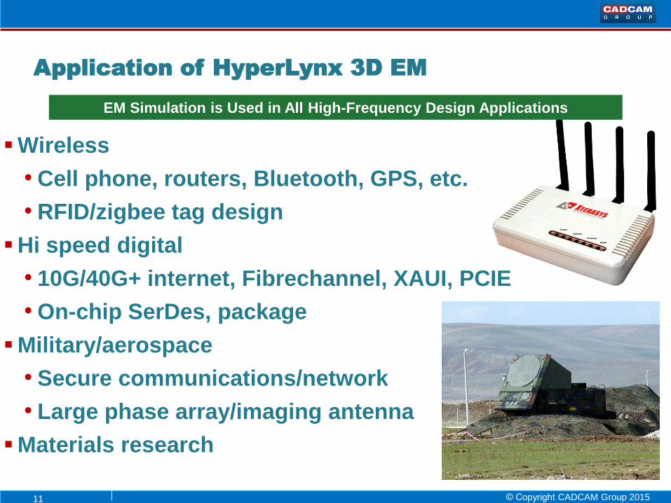
Wireless
• Cell phone, routers, Bluetooth, GPS, etc.
• RFID/zigbee tag design
Hi speed digital
• 10G/40G+ internet, Fibrechannel, XAUI, PCIE
• On-chip SerDes, package
Military/aerospace
• Secure communications/network
• Large phase array/imaging antenna
Materials research
Application of HyperLynx 3D EM
EM Simulation is Used in All High-Frequency Design Applications
12 © Copyright CADCAM Group 2015
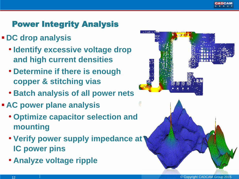
DC drop analysis
• Identify excessive voltage drop
and high current densities
• Determine if there is enough
copper & stitching vias
• Batch analysis of all power nets
AC power plane analysis
• Optimize capacitor selection and
mounting
• Verify power supply impedance at
IC power pins
• Analyze voltage ripple
Power Integrity Analysis
13 © Copyright CADCAM Group 2015
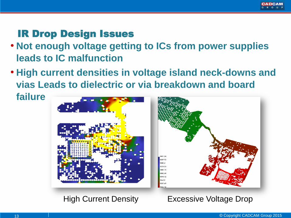
• Not enough voltage getting to ICs from power supplies
leads to IC malfunction
• High current densities in voltage island neck-downs and
vias Leads to dielectric or via breakdown and board
failure
IR Drop Design Issues
High Current Density Excessive Voltage Drop
14 © Copyright CADCAM Group 2015
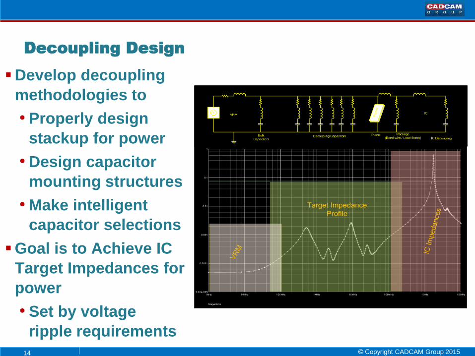
Develop decoupling
methodologies to
• Properly design
stackup for power
• Design capacitor
mounting structures
• Make intelligent
capacitor selections
Goal is to Achieve IC
Target Impedances for
power
• Set by voltage
ripple requirements
Decoupling Design

15 © Copyright CADCAM Group 2015
HyperLynx Plane Noise can help identify voltage ripple
exceeding IC power pin specifications
Plane noise is a result of target impedance and switching
currents
Plane Noise Analysis
16 © Copyright CADCAM Group 2015
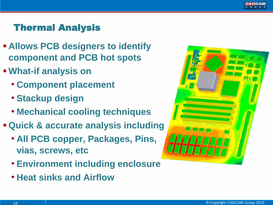
Allows PCB designers to identify
component and PCB hot spots
What-if analysis on
• Component placement
• Stackup design
• Mechanical cooling techniques
Quick & accurate analysis including
• All PCB copper, Packages, Pins,
vias, screws, etc
• Environment including enclosure
• Heat sinks and Airflow
Thermal Analysis

17 © Copyright CADCAM Group 2015
Scalable simulation solution built on xDxDesigner
Analog and full mixed signal simulation capability
• Support for analog and digital primitives
Standard language support
• VHDL, VHDL-AMS, Spice, & Verilog-A
Power ADMS and Eldo
simulation kernels
Full featured waveform
viewing with EZWave
• Including complex
waveform calculations
Analogue Simulation
18 © Copyright CADCAM Group 2015
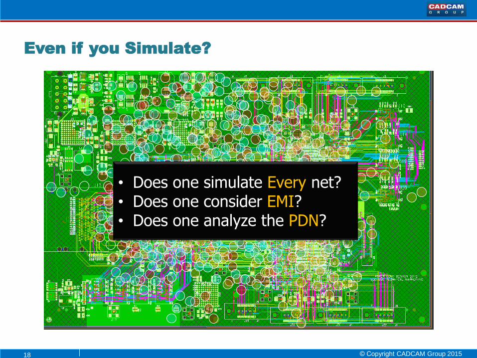
Even if you Simulate?
• Does one simulate Every net? • Does one consider EMI? • Does one analyze the PDN?
19 © Copyright CADCAM Group 2015
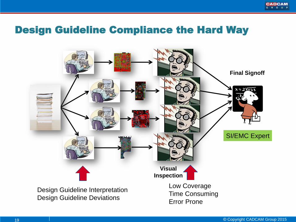
Design Guideline Compliance the Hard Way
Visual
Inspection
Design Guideline Interpretation
Design Guideline Deviations
Low Coverage
Time Consuming
Error Prone
Final Signoff
SI/EMC Expert
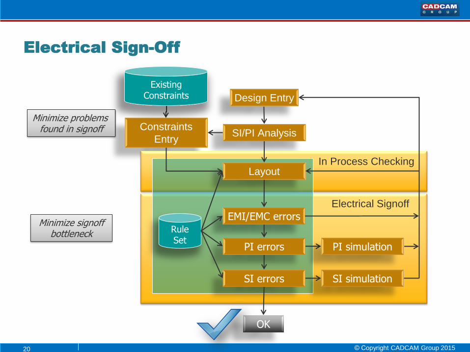
20 © Copyright CADCAM Group 2015
Design Entry
SI/PI Analysis Constraints
Entry
Minimize problems found in signoff
Minimize signoff bottleneck
Layout
EMI/EMC errors
OK
Electrical Signoff
PI errors
SI errors SI simulation
Rule Set
PI simulation
In Process Checking
Existing Constraints
Electrical Sign-Off
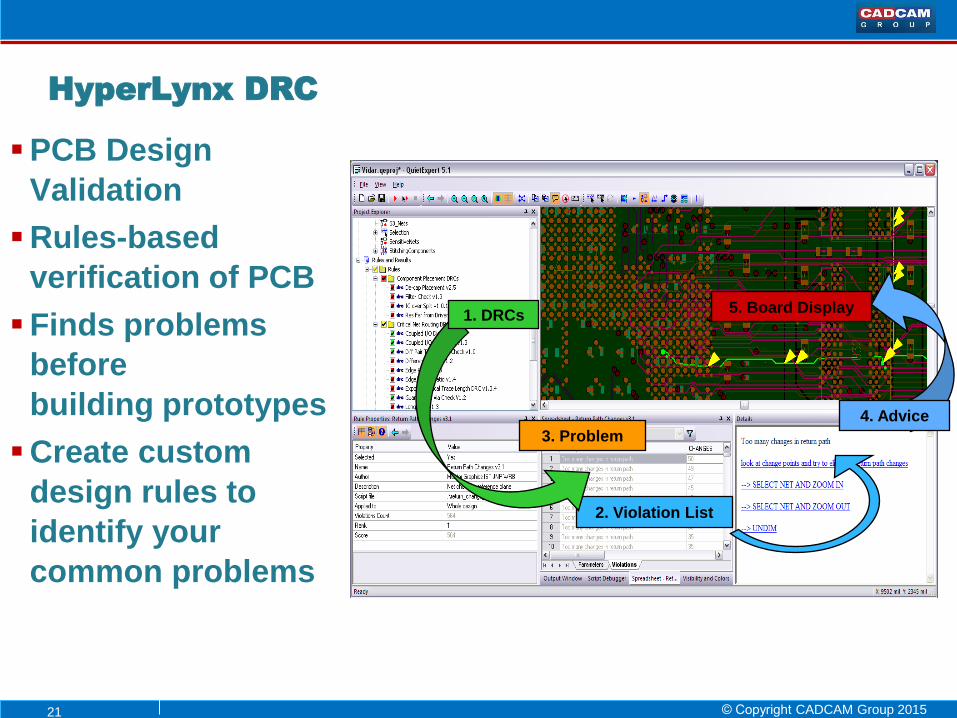
21 © Copyright CADCAM Group 2015
PCB Design
Validation
Rules-based
verification of PCB
Finds problems
before
building prototypes
Create custom
design rules to
identify your
common problems
5. Board Display
2. Violation List
1. DRCs
3. Problem
4. Advice
HyperLynx DRC
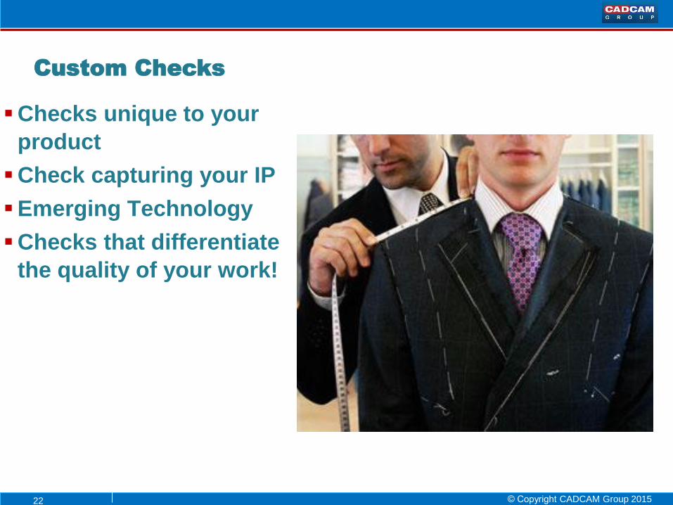
22 © Copyright CADCAM Group 2015
Checks unique to your
product
Check capturing your IP
Emerging Technology
Checks that differentiate
the quality of your work!
Custom Checks

23 © Copyright CADCAM Group 2015
Sometimes independent analysis
addresses only part of the issue
Integrated Analysis flow allows for
simulation across domains
Crossing Domains
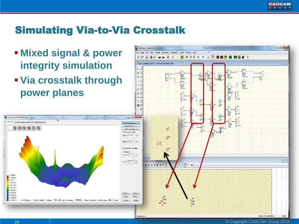
24 © Copyright CADCAM Group 2015
Mixed signal & power
integrity simulation
Via crosstalk through
power planes
Simulating Via-to-Via Crosstalk

25 © Copyright CADCAM Group 2015
Co-Simulation capabilities between PI and Thermal
• Power Integrity engine simulates power nets
provides power density “map” to thermal solver
• Thermal solver runs thermal analysis with component
dissipation & results from PI simulation
PI/Thermal Co-Simulation

26 © Copyright CADCAM Group 2015
PCB design is more than schematic and layout
• We know designs are becoming more complex
To meet reliability and time-to-market
• Project engineers must do PCB Analysis
Analysis is Core to the Design Process
Schematic Constraints Layout Prototype
Test /Bring-up
PCB
Analysis
PCB
Analysis
PCB
Analysis
“HyperLynx is now mandated as part
of our PCB design process.” - SEAKR Engineering

27 © Copyright CADCAM Group 2015
A Complete Analysis Solution
Reduce design cycle time
Develop constraints for
“first time right” design
Improve design reliability
Validate design intent
before prototyping
Verification in multiple domains
Accurate & fast time-to-results
HyperLynx enables ALL
engineers to drive analysis