electrical motor - oryx chapter -...
TRANSCRIPT

FANS FOR FIRE TUNNEL VENTILATION
FAN DESIGN
ELECTRICAL MOTOR
IMPORTANT ITEMS OF THE ELECTRICAL MOTOR
FANS FOR FIRE TUNNEL VENTILATION
• WINDING INSULATION
• WINDING SLOTS
• QUALITY OF THE IMPREGNATING VARNISH
• BEARINGS (C4 CLEARENCE)
• GREASE
• POWER SUPPLY CABLE
• TERMINAL PLATE MATERIAL (IN SURROUNDED BY SMOKE)
• MANUFACTURING PROCESS
FAN DESIGN

FANS FOR FIRE TUNNEL VENTILATION
FAN DESIGN
ELECTRICAL MOTOR

FANS FOR FIRE TUNNEL VENTILATION
FAN DESIGN
ELECTRICAL MOTOR

FANS FOR FIRE TUNNEL VENTILATION
FAN DESIGN
ELECTRICAL MOTOR

FANS FOR FIRE TUNNEL VENTILATION
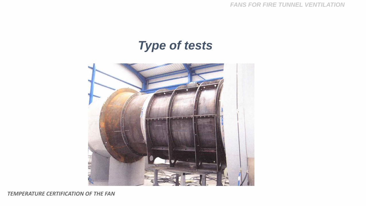
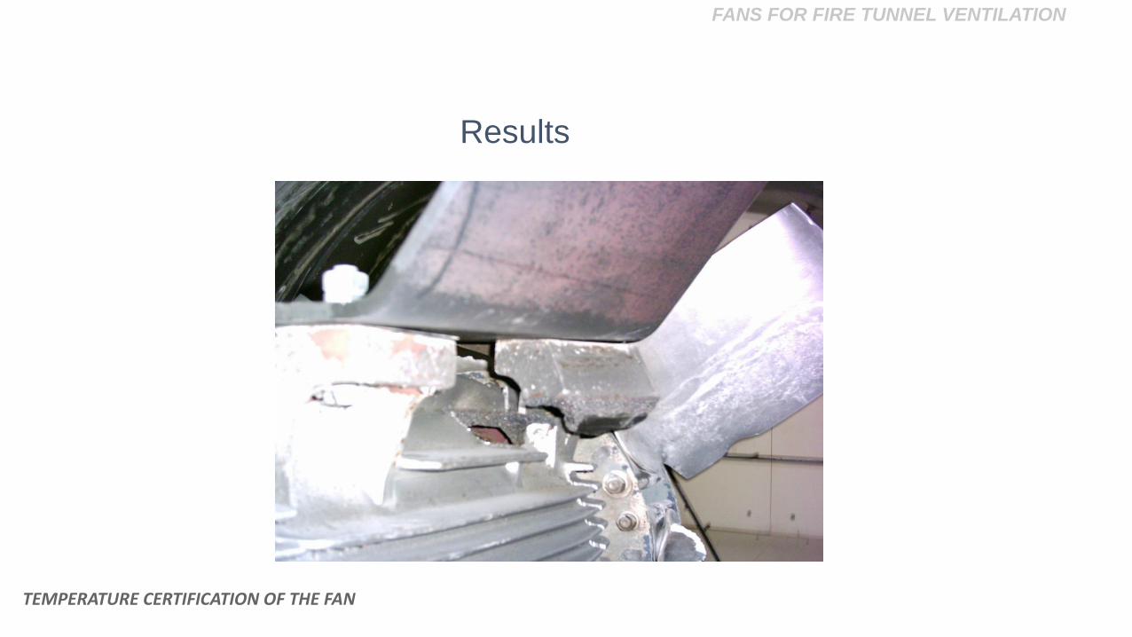
TEMPERATURE CERTIFICATION OF THE FAN
TEMPERATURE CERTIFICATION OF THE FAN

FANS FOR FIRE TUNNEL VENTILATION
TEMPERATURE CERTIFICATION OF THE FAN
European Standard EN 12101-3

FANS FOR FIRE TUNNEL VENTILATION
TEMPERATURE CERTIFICATION OF THE FAN
Classes of fire clasification

FANS FOR FIRE TUNNEL VENTILATION
TEMPERATURE CERTIFICATION OF THE FAN
Type of tests

FANS FOR FIRE TUNNEL VENTILATION
TEMPERATURE CERTIFICATION OF THE FAN
Type of tests
FANS FOR FIRE TUNNEL VENTILATION
TEMPERATURE CERTIFICATION OF THE FAN
Type of tests

FANS FOR FIRE TUNNEL VENTILATION
TEMPERATURE CERTIFICATION OF THE FAN
Type of tests

FANS FOR FIRE TUNNEL VENTILATION
TEMPERATURE CERTIFICATION OF THE FAN
Type of tests

FANS FOR FIRE TUNNEL VENTILATION
• Warm up period (dual purpose fans)
• Heat up period
• High temperature test
TESTING PROCEDURE
TEMPERATURE CERTIFICATION OF THE FAN

FANS FOR FIRE TUNNEL VENTILATION
TEMPERATURE CERTIFICATION OF THE FAN
Results

FANS FOR FIRE TUNNEL VENTILATION
TEMPERATURE CERTIFICATION OF THE FAN
Results

FANS FOR FIRE TUNNEL VENTILATION
TEMPERATURE CERTIFICATION OF THE FAN
Results

FANS FOR FIRE TUNNEL VENTILATION
TEMPERATURE CERTIFICATION OF THE FAN
Results

FANS FOR FIRE TUNNEL VENTILATION
TEMPERATURE CERTIFICATION OF THE FAN
Results
TEMPERATURE CERTIFICATION OF THE FAN
Results
FANS FOR FIRE TUNNEL VENTILATION

FANS FOR FIRE TUNNEL VENTILATION
INSTALLATION IN THE TUNNEL
INSTALLATION IN THE TUNNEL

FANS FOR FIRE TUNNEL VENTILATION
INSTALLATION IN THE TUNNEL
Possible commissioning problems
• Aerodynamic circuit

FANS FOR FIRE TUNNEL VENTILATION
INSTALLATION IN THE TUNNEL
Aerodynamic circuit

FANS FOR FIRE TUNNEL VENTILATION
INSTALLATION IN THE TUNNEL
• Aerodynamic circuit
• Location of the equipment
Possible commissioning problems

FANS FOR FIRE TUNNEL VENTILATION
INSTALLATION IN THE TUNNEL
Location of the equipment

FANS FOR FIRE TUNNEL VENTILATION
Location of the equipment
INSTALLATION IN THE TUNNEL

FANS FOR FIRE TUNNEL VENTILATION
• Aerodynamic circuit
• Location of the equipment
• Electric connection
Possible commissioning problems
INSTALLATION IN THE TUNNEL

FANS FOR FIRE TUNNEL VENTILATION
INSTALLATION IN THE TUNNEL
Electric connection

FANS FOR FIRE TUNNEL VENTILATION
INSTALLATION IN THE TUNNEL
Electric connection

FANS FOR FIRE TUNNEL VENTILATION
INSTALLATION IN THE TUNNEL
Electric connection

FANS FOR FIRE TUNNEL VENTILATION
• Adequate Fan Selection (Aerodynamic Design)
• Mechanical Design Capable of Withstanding the Stresses
to the Temperature of the Hot Fumes
• Adequate Electrical Motor
• Correct Installation in the Tunnel
SUMMARY
SUMMARY

Questions?
Roberto Arias
Technical DirectorZITRON, S.A.
FANS FOR FIRE TUNNEL VENTILATION

©2016 Air Movement and Control Association. All Rights Reserved.
Mark Stevens
Executive DirectorAMCA [email protected]
AVOIDING FAN SYSTEM EFFECT

This educational activity is protected by U.S. and International
copyright laws. Reproduction, distribution, display, and use of the
educational activity without written permission of the presenter is
prohibited.
© AMCA International
Copyright Materials

• Definition of system effect
• How to calculate system effect
• System effect’s effect on power consumption
• The difference between inlet and outlet system effect
• How to avoid system effect
Learning Objectives

Fan Efficiency
Eff
icie
nc
y, η
Airflow, Q

Regulation
Eff
icie
nc
y, η
Airflow, Q

What We Can Do
Eff
icie
nc
y, η
Airflow, Q

What We Can Do
Eff
icie
nc
y, η
Airflow, Q

Fan Testing for Air Performance

AMCA Standard 210
Test Fan
Auxiliary Fan
Nozzles
Fan Airflow
Piezometer Ring
Fan Static Pressure

Nozzle Wall

AMCA 210 Test Results
Airflow, Q

AMCA Standards 500-D & L
Test Damper
Auxiliary
Fan
Nozzles
Damper Airflow
Piezometer Ring
Damper Pressure Drop

Fan Operating Point
Airflow, Q
Operating Point

Speed Change
Airflow, Q

Damper Opening
Airflow, Q

Installed duct configuration does not match tested duct
configuration
System Effect 1st Definition
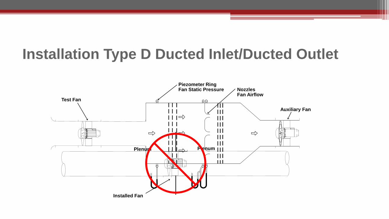
Installation Type D Ducted Inlet/Ducted Outlet
Test Fan
Auxiliary Fan
NozzlesFan Airflow
Piezometer Ring Fan Static Pressure
Installed Fan
PlenumPlenum
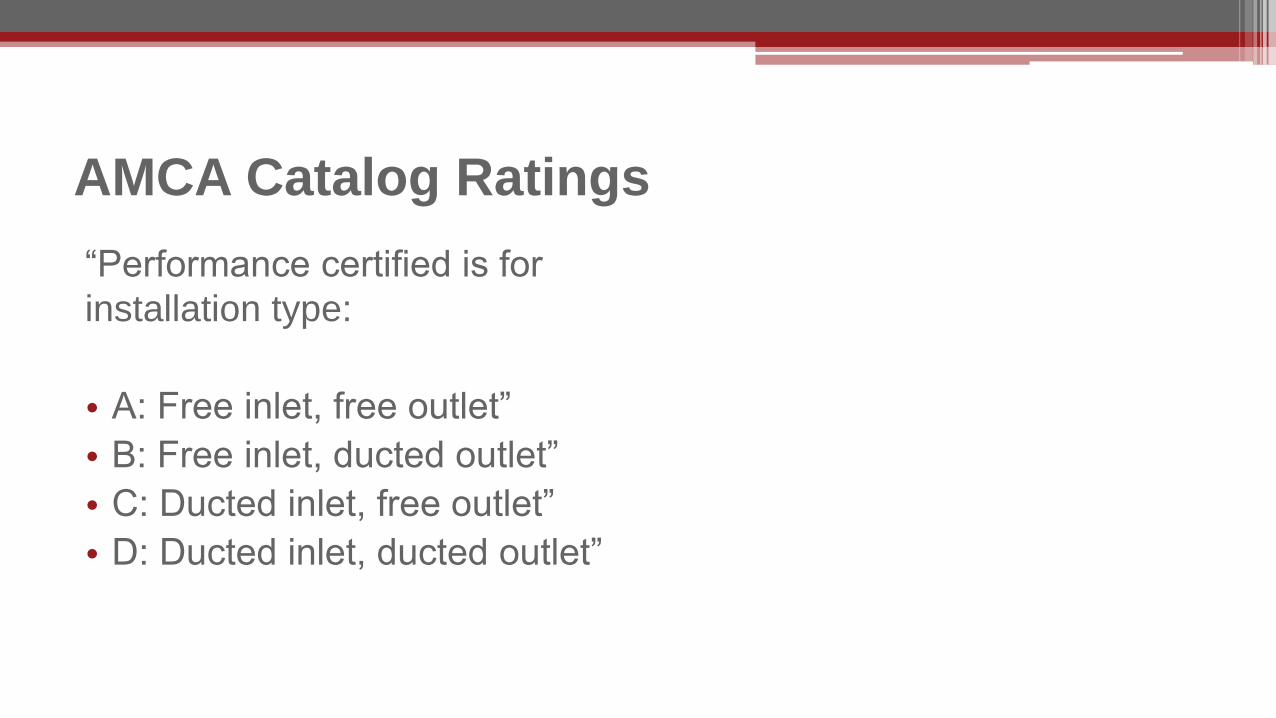
“Performance certified is for
installation type:
• A: Free inlet, free outlet”
• B: Free inlet, ducted outlet”
• C: Ducted inlet, free outlet”
• D: Ducted inlet, ducted outlet”
AMCA Catalog Ratings

Even when the tested duct configuration matches the installed duct
configuration, improper duct design can introduce adverse flow
conditions
System Effect 2nd Definition

Elbow Example


AMCA Publication 201 Plenum Example

E-F duct friction at 5000CMH (Q) 747 Pa (duct design)
E contraction loss-plenum to duct
50 Pa (part of duct system)
E PS energy required to create velocity at E
125 Pa (part of duct system)
D PV loss (also PT loss) at D as result of air velocity decrease, PS does not change from duct to plenum at D
0 Pa
C-D outlet duct on fan as tested 0 Pa
Required Fan Ps 922 Pa
Plenum Example

Plenum Example
Plenum

D-E duct friction at 5000CMH (Q) 747 Pa (duct design)
D contraction loss-plenum to duct
50 Pa (part of duct system)
D PS energy required to create velocity at D
125 Pa (part of duct system)
B-C SEF 149 Pa
B-C PV loss (also PT loss) at C as result of air velocity decrease, PS does not change from duct to plenum at C
0 Pa
Required Fan Ps 1071 Pa
Plenum Example

Assuming:
• Use of the same fan for both systems
• Can attain both operating points with a change in speed
• Speed change ratio; (1071/922)0.5 = 1.08
Plenum Example from AMCA 201
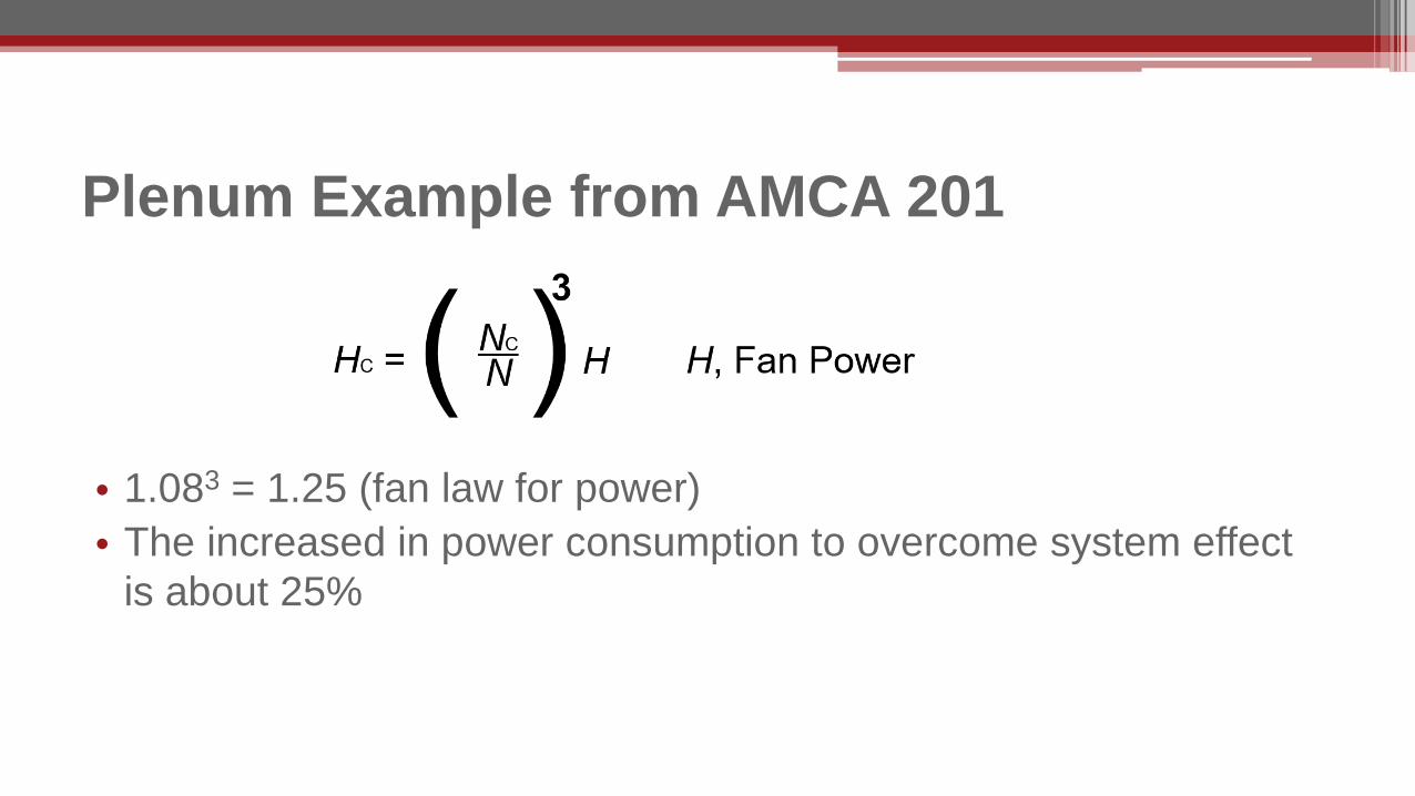
• 1.083 = 1.25 (fan law for power)
• The increased in power consumption to overcome system effect
is about 25%
Plenum Example from AMCA 201

8% Speed Change
25% More H
0
100
200
300
400
500
600
700
800
0 2 4 6 8 10 12 14
Airflow, Q
Pre
ss
ure
,P
0
0.5
1
1.5
2
2.5
Po
we
r,H
8% More Q

Inlet System Effect

Outlet System Effect

Before increasing speed
• Check with the manufacturer for max safe operating speed
• Determine expected power increase
Motor size
Electric service
• Expect more noise
Speed Changes


