electrical model of loudspeaker parameters -...
TRANSCRIPT


Contents0. Introduction 2 ..................................................................................................................................
2 .............................................................................................................................................................. 1. Loudspeaker’s Impedance 2 .......................................................................................................... 2. Why is this useful? 10 ..................................................................................................................... 3. How good is it? 13 ........................................................................................................................... 4. Bibliography 14 ................................................................................................................................

Electrical Model of Loudspeaker Parameters
PROJECT RYU 2/14 Stefan Andrei Chelariu
0. Introduction
In this article I present a way to model a loudspeaker driver’s parameters as an electrical circuitusing lumped elements. While this subject has been thoroughly explored, I will present mycontribution in the form of an online calculator that will easily do the calculations for you. The articlewill show how the model is derived and some of its uses. Loudspeaker enclosure can also be addedin the model and investigate the effects they have on the overall impedance that is present at theloudspeaker terminals.
It should be noted that this entire article refers to dynamic loudspeaker drivers only.
To try out the examples in this article yourselves you will need the following tools:
LTSPICE: http://www.linear.com/designtools/software/Electric Model Calculator: http://projectryu.com/app/electric_model/Some driver datasheet
1. Loudspeaker’s Impedance
In the beginning we should remind ourselves the nature of a driver’s impedance and what are theelements that contribute to this property. This will give us some insights into the advantages andlimitations the model has. In a driver we can clearly identify 3 sections corresponding to electrical,mechanical and acoustical domains and 2 energy conversions, from electrical to mechanical domainand from mechanical to acoustical domain respectively.
Figure 1. shows a representation of a driver’s physical parts and an equivalent electrical circuitusing lumped elements. Breaking the driver into its components allows us to easily identify whatcontributes to the driver’s behavior. On the electrical side we have the driver’s motor comprised ofthe voice coil and the magnetic circuit. The voice coil has a dc resistance property which is givenby wire material, diameter and length. Being a coil it will also have an inductance which isdetermined in part by the voice coil’s physical parameters such as size, number of wire turns, etc.The magnetic circuit has also a contribution on , first by creating a ferrous core and second fromeddy currents that form in the steel around the voice coil.
The effect of the steel creates what is referred to as a semi-inductance and can be observed athigher frequency where the impedance rises at 3db/octave instead of 6db/octave like a normalinductor. This complicates things as the semi-inductance can not be easily modeled using lumpedelements and it is not something that can be derived from fundamental properties of the driver.Some manufacturers do publish parameters that help model this but it is quite rare and manymodels are creating via curve matching technique which requires impedance measuring capabilities.For this reason the semi-inductance is not modeled in this online calculator.

Electrical Model of Loudspeaker Parameters
PROJECT RYU 3/14 Stefan Andrei Chelariu
Figure 1. Loudspeaker driver model
The magnetic circuit creates a static magnetic field in the gap with a flux density . The productbetween magnetic flux density and voice coil wire length is often called the motor forcefactor and it is basically the coupling factor between the electrical side and the mechanical side. Theforce exercised on the voice coil is equal to with being the electrical current through thevoice coil. We can see the coupling between the electrical side and mechanical side is thereforerepresented by a gyrator because we make the analogy that velocity corresponds to electricalcurrent and force corresponds to voltage. This is referred to as impedance analogy.
If we think in terms of efficiency, than we would like to generate as much force from electricalcurrent as possible by having a large coupling factor. is the product of magnetic flux density and voice coil wire length but increasing the later means also increasing which limits thecurrent therefore the best way to increase the coupling factor and efficiency is to increase .

Electrical Model of Loudspeaker Parameters
PROJECT RYU 4/14 Stefan Andrei Chelariu
On the mechanical side, fundamental properties such as mass and compliance are described aslumped electrical components such as resistor, inductor and capacitor. First we have the total massof the moving elements such as the cone, dust cap and voice coil combined with the contribution tothe moving mass by the spider and surround and finally the mass of the air load around thecone. Depending on the spider’s and surround’s geometry a fraction of their mass is added to themoving mass. This mass is represented by inductance .
Some papers treating this subject do not include the air load mass on the mechanical side andsuch they note the total mass as . While this makes sense, it is not often used.
Why is mass an inductance? There are two basic electric elements that can store energy, theinductance and the capacitance. To find out which one mass is, we need to apply Newton’s Law ofMotion stating where is force, is mass and is acceleration. For instantaneousvalues we can say:
Replacing and with their electrical analogues and we get:
which basically describes an inductance with .
The compliance is the inverse of spider’s and surround’s combined stiffness and is shown as acapacitor since the relationship between force, velocity and compliance is identical to that ofvoltage, current and capacitance:
The losses of the suspension system are shown as resistance . This is determined by thematerials and geometry of the voice coil former, spider and surround. On the mechanical side we
can see a resonant circuit being formed by and with and resistance acting as damping. I find it important to mention that above the resonant frequency , for
most of the bandwidth, the output of the driver is controlled by the mass .
Besides the mass contribution, the driver’s cone and it’s surface act as the transformer between themechanical side and the acoustical side. The bigger the cone’s surface the more mechanical energyis transformed into acoustical energy. In terms of efficiency it is desirable to have a large cone aslong as the mass does not increase. Depending on its geometry part of the surround surface alsocontributes to the total area .
On the acoustical side, in figure 1, we have a generic impedance element . This corresponds tothe radiation resistance for both front and back of the cone and the enclosure impedance. If noenclosure is modeled we would only keep the radiation resistance and treating the cone as

Electrical Model of Loudspeaker Parameters
PROJECT RYU 5/14 Stefan Andrei Chelariu
pulsating half sphere, we can define as:
where,
is air density,
is speed of sound in air,
is radius of a half sphere with same surface area as SD.
As can be seen in equation 4, is non-linear and depends on frequency and thus it cannot bemodeled using lumped elements. Let’s assume we have a 12″ driver with . Figure 2plots the value of the radiation resistance on the acoustical side as and after transformation tothe mechanical side as . Values of are quite small and we can neglect its influenceespecially when is much higher.
The transformation from acoustical side to mechanical side is straight forward:
Figure 2. Acoustic Radiation Resistance for a Driver with SD = 0.056 m^2

Electrical Model of Loudspeaker Parameters
PROJECT RYU 6/14 Stefan Andrei Chelariu
Because of it’s relatively low value and the fact that it cannot be modeled as a pure resistance, wewill leave out of the current model so we will only concern ourselves with the enclosure’selements on the acoustical side. If we would use instead of on the mechanical side thenwe should include the air mass around the front and back of the cone as inductors.
Figure 3 shows the electrical circuit equivalents for closed and vented enclosures. With a closedenclosure the air inside acts as a compliance and thus it is modeled as a capacitor and is definedby equation 6. If the enclosure is not air tight some of the air will leak. These losses are modeled asa resistor whose value depends on the parameter . With a vented enclosure we need to addthe mass of air that occupies the port’s volume as inductor . This air acts as a mass because itwill move back and forth as the cone vibrates unlike the air inside the enclosure who is elasticcompressing or rarefying under force and recovering when the force is removed.
Figure 3. Loudspeaker Enclosure Model
with,
is enclosure volume,
is density of air,
is speed of sound,

Electrical Model of Loudspeaker Parameters
PROJECT RYU 7/14 Stefan Andrei Chelariu
is port lenght,
is port area
The circuit in figure 1 while offers an insight into the role each element plays, it’s not in a usefulform due to the BL and SD transformations. To study the electrical impedance it would make senseto move all the elements on the electrical side and then apply circuit theory. The transformationfrom the acoustical side to mechanical side is defined by the following equation:
where,
is the impedance on the mechanical side,
is the impedance on the acoustical side.
Figure 4. Converting components from acoustical side to mechanical side
The transformation from the mechanical side to electrical is a little bit more complicated due to thegyrator. It will convert series circuits to parallel circuits and vice-versa and it will convert inductorsto capacitors and vice-versa. Figure 5 shows the equivalent electrical circuit with all elementstransferred on the electrical side. The formulas for the conversion are listed below:

Electrical Model of Loudspeaker Parameters
PROJECT RYU 8/14 Stefan Andrei Chelariu

Electrical Model of Loudspeaker Parameters
PROJECT RYU 9/14 Stefan Andrei Chelariu
Figure 5. Converting components from mechanical side to electrical side
With no gyrators or transformers in our circuit we can easily calculate the impedance presented atthe generator . Using a tool such as LTSpice we can create the above circuit and define ourdesired simulation. To get the impedance presented at the generator we should define an ac
simulation and plot .
Analytically, we can brake the circuit and deal with groups of parallel or series connections one at atime. Let’s consider the vented enclosure circuit. The impedance of the series elementscorresponding to the enclosure will be treated in parallel with the driver’s components and theresultant impedance will be treated in series with the voice coil components. Expressing the result inCartesian form we get the following:

Electrical Model of Loudspeaker Parameters
PROJECT RYU 10/14 Stefan Andrei Chelariu
where,
is the total equivalent impedance of the parallel circuit to the right of ,
is the real part of ,
is the imaginary part of ,
is the total equivalent impedance of and ,
is the total equivalent impedance presented at the generator ,
is the magnitude of ,
is the phase of .
2. Why is this useful?
For our examples let’s consider the following driver:
Resonance Frequency, Fs [Hz]: 57
DC Resistance, Re[Ω]: 5.5
Inductance, Le[mH]: 0.8
Motor Force Factor, BL[Tm]: 6
Compliance, Cms[mm/N]: 0.29
Mechanical Loses, Rms[kg/s]: 0.65
Moving Mass, Mms[g]: 26.6
Piston Surface, SD[ ]: 0.049
Using the online calculator, let’s build the equivalent circuit model for this loudspeaker. Let say thisloudspeaker will be in a vented box with a volume of 100 liters, a vent of 50 mm in length and 70

Electrical Model of Loudspeaker Parameters
PROJECT RYU 11/14 Stefan Andrei Chelariu
mm in diameter.
Figure 6. Speaker Equivalent Electrical Circuit
The online calculator will provide the values for all the components in the circuit. All we need to donow is to build the circuit in LTSpice and run an ac simulation. To get the impedance curve in figure
7, we will plot . The resultant curve is the familiar vented loudspeaker impedance.

Electrical Model of Loudspeaker Parameters
PROJECT RYU 12/14 Stefan Andrei Chelariu
Figure 7. Loudspeaker LTSpice Simulation
We can continue our analysis for example by stepping any component value from the circuit and seehow the impedance is affected. In this case, let’s vary which corresponds to the enclosure’svolume. This can be achieved by adding a directive in LTSpice and defining the min, max andinterval parameters. The result in figure 8 shows how we can easily check the enclosure volume forour desired LF alignment.
Figure 8. Parameter Step in Loudspeaker Simulation
Electrical Model of Loudspeaker Parameters
PROJECT RYU 13/14 Stefan Andrei Chelariu
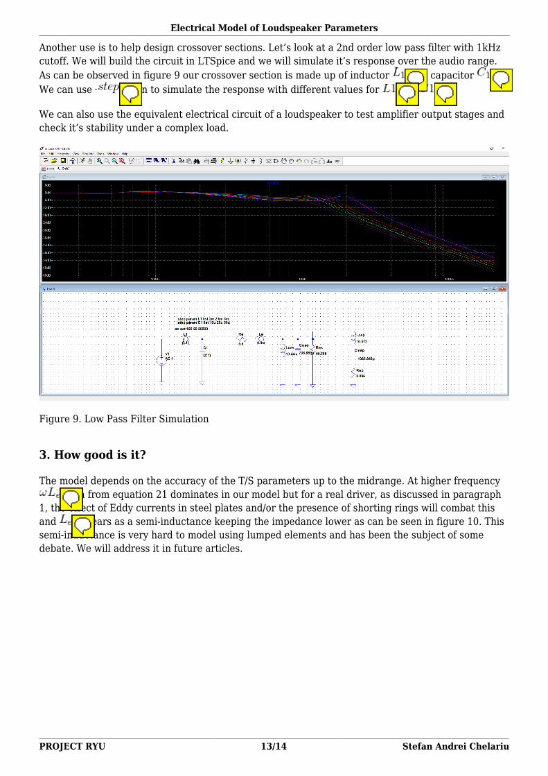
Another use is to help design crossover sections. Let’s look at a 2nd order low pass filter with 1kHzcutoff. We will build the circuit in LTSpice and we will simulate it’s response over the audio range.As can be observed in figure 9 our crossover section is made up of inductor and capacitor .We can use again to simulate the response with different values for and .
We can also use the equivalent electrical circuit of a loudspeaker to test amplifier output stages andcheck it’s stability under a complex load.
Figure 9. Low Pass Filter Simulation
3. How good is it?
The model depends on the accuracy of the T/S parameters up to the midrange. At higher frequency term from equation 21 dominates in our model but for a real driver, as discussed in paragraph
1, the effect of Eddy currents in steel plates and/or the presence of shorting rings will combat thisand appears as a semi-inductance keeping the impedance lower as can be seen in figure 10. Thissemi-inductance is very hard to model using lumped elements and has been the subject of somedebate. We will address it in future articles.

Electrical Model of Loudspeaker Parameters
PROJECT RYU 14/14 Stefan Andrei Chelariu
Figure 10. Simulated vs Real Loudspeaker Impedance
4. Bibliography
Handbook for Sound Engineers, edited by Glen Ballou, Chapter 21 Loudspeakers by TomDanley and Doug Jones
Wikipedia, Impedance Analogy, https://en.wikipedia.org/wiki/Impedance_analogyAcoustics: Sound Fields and Transducers, Leo Beranek, Tim Mellow, Academic Press 2012Impedance Analysis of Subwoofer System, ARTHUR P. BERKHOFF, J.AudioEng.Soc.,Vol.42,No.1/2,1994Loudspeakers’ Electric Models for Study of the Efforts in Audio Power Amplifiers, RosalfonsoBortoni, Homero Sette Silva, AES Convention Paper 5911An empirical model for loudspeaker motor impedance, J R Wright, AES 86th Convention 1989