electrical measuring and test equipment; part 1: …u.dianyuan.com › bbs › u › 58 ›...
TRANSCRIPT
UL 61010B-1
ISBN 0–7629–0839–4
Electrical Measuring and TestEquipment; Part 1: GeneralRequirements


Underwriters Laboratories Inc. (UL)333 Pfingsten RoadNorthbrook, IL 60062-2096
UL Standard for Safety for Electrical Measuring and Test Equipment Part 1: General Requirements, UL61010B-1
First Edition, Dated January 24, 2003
Summary of Topics
These revisions adopt the following changes in requirements:
1. Change in Number and Format of UL 3111–1 (number changed to UL 61010B-1). Inaddition to changing the standard number, UL has editorially reformatted the standard.The reformatting includes, but is not limited to, referring to “deviations” as “nationaldifferences” and incorporating them into the body of the standard.
2. Having the first edition of UL 61010B-1 correlate with the requirements in AmendmentNo. 2 to IEC Publication 61010–1.
UL Standards for Safety are developed and maintained in the Standard Generalized Markup Language(SGML). SGML -- an international standard (ISO 8879-1986) -- is a descriptive markup language thatdescribes a document’s structure and purpose, rather than its physical appearance on a page. Due toformatting differences resulting from the use of UL’s new electronic publishing system, please note thatadditional pages (on which no requirements have been changed) may be included in revision pages dueto relocation of existing text and reformatting of the Standard.
Text that has been changed in any manner is marked with a vertical line in the margin. Changes inrequirements are marked with a vertical line in the margin and are followed by an effective date noteindicating the date of publication or the date on which the changed requirement becomes effective.
The new and/or revised requirements are substantially in accordance with UL’s Bulletin on this subjectdated July 5, 2002. The bulletin is now obsolete and may be discarded.
The master for this Standard at UL’s Northbrook Office is the official document insofar as it relates to aUL service and the compliance of a product with respect to the requirements for that product and service,or if there are questions regarding the accuracy of this Standard.
UL’s Standards for Safety are copyrighted by UL. Neither a printed copy of a Standard, nor the distributiondiskette for a Standard-on-Diskette and the file for the Standard on the distribution diskette should bealtered in any way. All of UL’s Standards and all copyrights, ownerships, and rights regarding thoseStandards shall remain the sole and exclusive property of UL.
All rights reserved. No part of this publication may be reproduced, stored in a retrieval system, ortransmitted in any form by any means, electronic, mechanical photocopying, recording, or otherwisewithout prior permission of UL.
Revisions of UL Standards for Safety are issued from time to time. A UL Standard for Safety is currentonly if it incorporates the most recently adopted revisions.
UL provides this Standard ″as is″ without warranty of any kind, either expressed or implied, including butnot limited to, the implied warranties of merchantability or fitness for any purpose.
JANUARY 24, 2003 − UL 61010B-1 tr1

In no event will UL be liable for any special, incidental, consequential, indirect or similar damages,including loss of profits, lost savings, loss of data, or any other damages arising out of the use of or theinability to use this Standard, even if UL or an authorized UL representative has been advised of thepossibility of such damage. In no event shall UL’s liability for any damage ever exceed the price paid forthis Standard, regardless of the form of the claim.
UL will attempt to answer support requests concerning electronic versions of its Standards. However, thissupport service is offered on a reasonable efforts basis only, and UL may not be able to resolve everysupport request. UL supports the electronic versions of its Standards only if they are used under theconditions and operating systems for which it is intended. UL’s support policies may change fromtime-to-time without notification.
UL reserves the right to change the format, presentation, file types and formats, delivery methods andformats, and the like of both its printed and electronic Standards without prior notice.
Purchasers of the electronic versions of UL’s Standards for Safety agree to defend, indemnify, and holdUL harmless from and against any loss, expense, liability, damage, claim, or judgement (includingreasonable attorney’s fees) resulting from any error or deviation introduced while purchaser is storing anelectronic Standard on the purchaser’s computer system.
If a single-user version electronic Standard was purchased, one copy of this Standard may be stored onthe hard disk of a single personal computer, or on a single LAN file-server or the permanent storagedevice of a multiple-user computer in such a manner that this Standard may only be accessed by one userat a time and for which there is no possibility of multiple concurrent access.
If a multiple-user version electronic Standard was purchased, one copy of the Standard may be stored ona single LAN file-server, or on the permanent storage device of a multiple-user computer, or on an Intranetserver. The number of concurrent users shall not exceed the number of users authorized.
Electronic Standards are intended for on-line use, such as for viewing the requirements of a Standard,conducting a word search, and the like. Only one copy of the Standard may be printed from eachsingle-user version of an electronic Standard. Only one copy of the Standard may be printed for eachauthorized user of a multiple-user version of an electronic Standard. Because of differences in thecomputer/software/printer setup used by UL and those of electronic Standards purchasers, the printedcopy obtained by a purchaser may not look exactly like the on-line screen view or the printed Standard.
An employee of an organization purchasing a UL Standard can make a copy of the page or pages beingviewed for their own fair and/or practical internal use.
The requirements in this Standard are now in effect, except for those paragraphs, sections, tables, figures,and/or other elements of the Standard having future effective dates as indicated in the note following theaffected item. The prior text for requirements that have been revised and that have a future effective dateare located after the Standard, and are preceded by a ″SUPERSEDED REQUIREMENTS″ notice.
New product submittals made prior to a specified future effective date will be judged under all of therequirements in this Standard including those requirements with a specified future effective date, unlessthe applicant specifically requests that the product be judged under the current requirements. However, ifthe applicant elects this option, it should be noted that compliance with all the requirements in thisStandard will be required as a condition of continued Listing and Follow-Up Services after the effectivedate, and understanding of this should be signified in writing.
JANUARY 24, 2003 − UL 61010B-1tr2

It should be noted that in an effort to more closely match the IEC text, information in the following checklistrelated to annexes may not correlate correctly at this time with the annex identification in the annexesthemselves. This information will be correct in future revision cycles.
Copyright © 2003 Underwriters Laboratories Inc.
This Standard consists of pages dated as shown in the following checklist:
Page Date
1-100 . . . . . . . . . . . . . . . . . . . . . . . . . . . . . . . . . . . . . . . . . . . . . . . . . . . . . . . . . . . . . . . . . . . . . . . . January 24, 2003A1-A4 . . . . . . . . . . . . . . . . . . . . . . . . . . . . . . . . . . . . . . . . . . . . . . . . . . . . . . . . . . . . . . . . . . . . . . . . January 24, 2003B1-B2 . . . . . . . . . . . . . . . . . . . . . . . . . . . . . . . . . . . . . . . . . . . . . . . . . . . . . . . . . . . . . . . . . . . . . . . . January 24, 2003C1-C2. . . . . . . . . . . . . . . . . . . . . . . . . . . . . . . . . . . . . . . . . . . . . . . . . . . . . . . . . . . . . . . . . . . . . . . . January 24, 2003D1-D24 . . . . . . . . . . . . . . . . . . . . . . . . . . . . . . . . . . . . . . . . . . . . . . . . . . . . . . . . . . . . . . . . . . . . . . January 24, 2003E1-E8 . . . . . . . . . . . . . . . . . . . . . . . . . . . . . . . . . . . . . . . . . . . . . . . . . . . . . . . . . . . . . . . . . . . . . . . . January 24, 2003F1-F6 . . . . . . . . . . . . . . . . . . . . . . . . . . . . . . . . . . . . . . . . . . . . . . . . . . . . . . . . . . . . . . . . . . . . . . . . January 24, 2003G1-G2 . . . . . . . . . . . . . . . . . . . . . . . . . . . . . . . . . . . . . . . . . . . . . . . . . . . . . . . . . . . . . . . . . . . . . . . January 24, 2003H1-H2. . . . . . . . . . . . . . . . . . . . . . . . . . . . . . . . . . . . . . . . . . . . . . . . . . . . . . . . . . . . . . . . . . . . . . . . January 24, 2003I1-I2 . . . . . . . . . . . . . . . . . . . . . . . . . . . . . . . . . . . . . . . . . . . . . . . . . . . . . . . . . . . . . . . . . . . . . . . . . January 24, 2003J1-J2 . . . . . . . . . . . . . . . . . . . . . . . . . . . . . . . . . . . . . . . . . . . . . . . . . . . . . . . . . . . . . . . . . . . . . . . . January 24, 2003K1-K2 . . . . . . . . . . . . . . . . . . . . . . . . . . . . . . . . . . . . . . . . . . . . . . . . . . . . . . . . . . . . . . . . . . . . . . . . January 24, 2003L1-L2 . . . . . . . . . . . . . . . . . . . . . . . . . . . . . . . . . . . . . . . . . . . . . . . . . . . . . . . . . . . . . . . . . . . . . . . . January 24, 2003M1-M4 . . . . . . . . . . . . . . . . . . . . . . . . . . . . . . . . . . . . . . . . . . . . . . . . . . . . . . . . . . . . . . . . . . . . . . . January 24, 2003
JANUARY 24, 2003 − UL 61010B-1 tr3

JANUARY 24, 2003 − UL 61010B-1tr4
No Text on This Page

JANUARY 24, 2003
1
UL 61010B-1
Electrical Measuring and Test Equipment Part 1: General Requirements
Prior to this first edition numbered UL 61010B-1, the requirements for productscovered by this standard were included in the first edition of UL 3111–1. Thisstandard replaces UL 3111–1.
First Edition
January 24, 2003
An effective date included as a note immediately following certain requirementsis one established by Underwriters Laboratories Inc.
Revisions of this standard will be made by issuing revised or additional pagesbearing their date of issue. A UL Standard is current only if it incorporates themost recently adopted revisions, all of which are itemized on the transmittal noticethat accompanies the latest set of revised requirements.
ISBN 0–7629–0839–4
COPYRIGHT © 2003 UNDERWRITERS LABORATORIES INC.

JANUARY 24, 2003UL 61010B-12
No Text on This Page

CONTENTS
Preface (UL) . . . . . . . . . . . . . . . . . . . . . . . . . . . . . . . . . . . . . . . . . . . . . . . . . . . . . . . . . . . . . . . . . . . . . . . . . . . . . . . .8
FOREWORD . . . . . . . . . . . . . . . . . . . . . . . . . . . . . . . . . . . . . . . . . . . . . . . . . . . . . . . . . . . . . . . . . . . . . . . . . . . . . . .10
NATIONAL DIFFERENCES . . . . . . . . . . . . . . . . . . . . . . . . . . . . . . . . . . . . . . . . . . . . . . . . . . . . . . . . . . . . . . . . . .11
FOREWORD . . . . . . . . . . . . . . . . . . . . . . . . . . . . . . . . . . . . . . . . . . . . . . . . . . . . . . . . . . . . . . . . . . . . . . . . . . . . . . .12
INTRODUCTION . . . . . . . . . . . . . . . . . . . . . . . . . . . . . . . . . . . . . . . . . . . . . . . . . . . . . . . . . . . . . . . . . . . . . . . . . . .14
1 Scope and object . . . . . . . . . . . . . . . . . . . . . . . . . . . . . . . . . . . . . . . . . . . . . . . . . . . . . . . . . . . . . . . . . . . .151.1 Scope . . . . . . . . . . . . . . . . . . . . . . . . . . . . . . . . . . . . . . . . . . . . . . . . . . . . . . . . . . . . . . . . . . . . . . . .151.2 Object . . . . . . . . . . . . . . . . . . . . . . . . . . . . . . . . . . . . . . . . . . . . . . . . . . . . . . . . . . . . . . . . . . . . . . .171.3 Verification . . . . . . . . . . . . . . . . . . . . . . . . . . . . . . . . . . . . . . . . . . . . . . . . . . . . . . . . . . . . . . . . . . .171.4 Environmental conditions . . . . . . . . . . . . . . . . . . . . . . . . . . . . . . . . . . . . . . . . . . . . . . . . . . . . . . .18
2 Normative references . . . . . . . . . . . . . . . . . . . . . . . . . . . . . . . . . . . . . . . . . . . . . . . . . . . . . . . . . . . . . . . . .182.1 IEC standards . . . . . . . . . . . . . . . . . . . . . . . . . . . . . . . . . . . . . . . . . . . . . . . . . . . . . . . . . . . . . . . .182.2 ISO standards . . . . . . . . . . . . . . . . . . . . . . . . . . . . . . . . . . . . . . . . . . . . . . . . . . . . . . . . . . . . . . . .20
3 Definitions . . . . . . . . . . . . . . . . . . . . . . . . . . . . . . . . . . . . . . . . . . . . . . . . . . . . . . . . . . . . . . . . . . . . . . . . . .213.1 Equipment and states of equipment . . . . . . . . . . . . . . . . . . . . . . . . . . . . . . . . . . . . . . . . . . . . .213.2 Parts and accessories . . . . . . . . . . . . . . . . . . . . . . . . . . . . . . . . . . . . . . . . . . . . . . . . . . . . . . . . .213.3 Electrical quantities . . . . . . . . . . . . . . . . . . . . . . . . . . . . . . . . . . . . . . . . . . . . . . . . . . . . . . . . . . . .223.4 Tests . . . . . . . . . . . . . . . . . . . . . . . . . . . . . . . . . . . . . . . . . . . . . . . . . . . . . . . . . . . . . . . . . . . . . . . .223.5 Safety terms . . . . . . . . . . . . . . . . . . . . . . . . . . . . . . . . . . . . . . . . . . . . . . . . . . . . . . . . . . . . . . . . . .223.6 Insulation . . . . . . . . . . . . . . . . . . . . . . . . . . . . . . . . . . . . . . . . . . . . . . . . . . . . . . . . . . . . . . . . . . . . .233.7 Insulation co-ordination . . . . . . . . . . . . . . . . . . . . . . . . . . . . . . . . . . . . . . . . . . . . . . . . . . . . . . . . .233.8 Mains . . . . . . . . . . . . . . . . . . . . . . . . . . . . . . . . . . . . . . . . . . . . . . . . . . . . . . . . . . . . . . . . . . . . . . . .24
4 Tests . . . . . . . . . . . . . . . . . . . . . . . . . . . . . . . . . . . . . . . . . . . . . . . . . . . . . . . . . . . . . . . . . . . . . . . . . . . . . . .244.1 General . . . . . . . . . . . . . . . . . . . . . . . . . . . . . . . . . . . . . . . . . . . . . . . . . . . . . . . . . . . . . . . . . . . . . .244.2 Sequence of tests . . . . . . . . . . . . . . . . . . . . . . . . . . . . . . . . . . . . . . . . . . . . . . . . . . . . . . . . . . . . .254.3 Reference test conditions . . . . . . . . . . . . . . . . . . . . . . . . . . . . . . . . . . . . . . . . . . . . . . . . . . . . . .254.4 Testing in SINGLE FAULT CONDITION . . . . . . . . . . . . . . . . . . . . . . . . . . . . . . . . . . . . . . . . . . . . . . . . . .28
5 Marking and documentation . . . . . . . . . . . . . . . . . . . . . . . . . . . . . . . . . . . . . . . . . . . . . . . . . . . . . . . . . . .325.1 Marking . . . . . . . . . . . . . . . . . . . . . . . . . . . . . . . . . . . . . . . . . . . . . . . . . . . . . . . . . . . . . . . . . . . . . .325.2 Warning markings . . . . . . . . . . . . . . . . . . . . . . . . . . . . . . . . . . . . . . . . . . . . . . . . . . . . . . . . . . . . .395.3 Durability of markings . . . . . . . . . . . . . . . . . . . . . . . . . . . . . . . . . . . . . . . . . . . . . . . . . . . . . . . . . .405.4 Documentation . . . . . . . . . . . . . . . . . . . . . . . . . . . . . . . . . . . . . . . . . . . . . . . . . . . . . . . . . . . . . . . .40
6 Protection against electric shock . . . . . . . . . . . . . . . . . . . . . . . . . . . . . . . . . . . . . . . . . . . . . . . . . . . . . . .426.1 General . . . . . . . . . . . . . . . . . . . . . . . . . . . . . . . . . . . . . . . . . . . . . . . . . . . . . . . . . . . . . . . . . . . . . .426.2 Determination of ACCESSIBLE parts . . . . . . . . . . . . . . . . . . . . . . . . . . . . . . . . . . . . . . . . . . . . . . . .436.3 Permissible limits for ACCESSIBLE parts . . . . . . . . . . . . . . . . . . . . . . . . . . . . . . . . . . . . . . . . . . . .446.4 Protection in NORMAL CONDITION . . . . . . . . . . . . . . . . . . . . . . . . . . . . . . . . . . . . . . . . . . . . . . . . . . .496.5 Protection in SINGLE FAULT CONDITION . . . . . . . . . . . . . . . . . . . . . . . . . . . . . . . . . . . . . . . . . . . . . . .506.6 External circuits . . . . . . . . . . . . . . . . . . . . . . . . . . . . . . . . . . . . . . . . . . . . . . . . . . . . . . . . . . . . . . .536.7 CLEARANCES and CREEPAGE DISTANCES . . . . . . . . . . . . . . . . . . . . . . . . . . . . . . . . . . . . . . . . . . . . . . . .556.8 Dielectric strength tests . . . . . . . . . . . . . . . . . . . . . . . . . . . . . . . . . . . . . . . . . . . . . . . . . . . . . . . .566.9 Constructional requirements for protection against electric shock . . . . . . . . . . . . . . . . . . . .586.10 Connection to mains supply source and connections between parts of equipment . . . .606.10.4DV.1 General . . . . . . . . . . . . . . . . . . . . . . . . . . . . . . . . . . . . . . . . . . . . . . . . . . . . . . . . . . . . . . .656.10.4DV.2 Wiring TERMINALS . . . . . . . . . . . . . . . . . . . . . . . . . . . . . . . . . . . . . . . . . . . . . . . . . . . . . . . .65
JANUARY 24, 2003 UL 61010B-1 3

6.10.4DV.3 Leads . . . . . . . . . . . . . . . . . . . . . . . . . . . . . . . . . . . . . . . . . . . . . . . . . . . . . . . . . . . . . . . . .666.10.4DV.4 TERMINAL and lead identification . . . . . . . . . . . . . . . . . . . . . . . . . . . . . . . . . . . . . . . . . . .666.10.4DV.5 ENCLOSURE requirements for conduit entry . . . . . . . . . . . . . . . . . . . . . . . . . . . . . . . . . .676.10.4DV.6 Conduit ENCLOSURE entry tests . . . . . . . . . . . . . . . . . . . . . . . . . . . . . . . . . . . . . . . . . . . .676.11 TERMINALS . . . . . . . . . . . . . . . . . . . . . . . . . . . . . . . . . . . . . . . . . . . . . . . . . . . . . . . . . . . . . . . . . . . .696.12 Disconnection from supply source . . . . . . . . . . . . . . . . . . . . . . . . . . . . . . . . . . . . . . . . . . . . . .71
7 Protection against mechanical hazards . . . . . . . . . . . . . . . . . . . . . . . . . . . . . . . . . . . . . . . . . . . . . . . . .737.1 General . . . . . . . . . . . . . . . . . . . . . . . . . . . . . . . . . . . . . . . . . . . . . . . . . . . . . . . . . . . . . . . . . . . . . .737.2 Moving parts . . . . . . . . . . . . . . . . . . . . . . . . . . . . . . . . . . . . . . . . . . . . . . . . . . . . . . . . . . . . . . . . . .747.3 Stability . . . . . . . . . . . . . . . . . . . . . . . . . . . . . . . . . . . . . . . . . . . . . . . . . . . . . . . . . . . . . . . . . . . . . .747.4 Provisions for lifting and carrying . . . . . . . . . . . . . . . . . . . . . . . . . . . . . . . . . . . . . . . . . . . . . . . .757.5 Expelled parts . . . . . . . . . . . . . . . . . . . . . . . . . . . . . . . . . . . . . . . . . . . . . . . . . . . . . . . . . . . . . . . .75
8 Mechanical resistance to shock and impact . . . . . . . . . . . . . . . . . . . . . . . . . . . . . . . . . . . . . . . . . . . . .758.1 Rigidity test . . . . . . . . . . . . . . . . . . . . . . . . . . . . . . . . . . . . . . . . . . . . . . . . . . . . . . . . . . . . . . . . . . .768.2 Impact hammer test . . . . . . . . . . . . . . . . . . . . . . . . . . . . . . . . . . . . . . . . . . . . . . . . . . . . . . . . . . .768.3 Not used. . . . . . . . . . . . . . . . . . . . . . . . . . . . . . . . . . . . . . . . . . . . . . . . . . . . . . . . . . . . . . . . . . . . . .778.4 Drop test . . . . . . . . . . . . . . . . . . . . . . . . . . . . . . . . . . . . . . . . . . . . . . . . . . . . . . . . . . . . . . . . . . . . .77
9 Equipment temperature limits and protection against the spread of fire . . . . . . . . . . . . . . . . . . . . .789.1 General . . . . . . . . . . . . . . . . . . . . . . . . . . . . . . . . . . . . . . . . . . . . . . . . . . . . . . . . . . . . . . . . . . . . . .789.2 Temperature tests . . . . . . . . . . . . . . . . . . . . . . . . . . . . . . . . . . . . . . . . . . . . . . . . . . . . . . . . . . . . .799.3 Guards . . . . . . . . . . . . . . . . . . . . . . . . . . . . . . . . . . . . . . . . . . . . . . . . . . . . . . . . . . . . . . . . . . . . . . .809.4 FIELD WIRING TERMINAL boxes . . . . . . . . . . . . . . . . . . . . . . . . . . . . . . . . . . . . . . . . . . . . . . . . . . . . . .809.5 Overtemperature protection devices . . . . . . . . . . . . . . . . . . . . . . . . . . . . . . . . . . . . . . . . . . . . .809.6 Overcurrent protection . . . . . . . . . . . . . . . . . . . . . . . . . . . . . . . . . . . . . . . . . . . . . . . . . . . . . . . . .81
10 Resistance to heat . . . . . . . . . . . . . . . . . . . . . . . . . . . . . . . . . . . . . . . . . . . . . . . . . . . . . . . . . . . . . . . . . .8210.1 Integrity of CLEARANCES and CREEPAGE DISTANCES . . . . . . . . . . . . . . . . . . . . . . . . . . . . . . . . . . . .8210.2 Resistance to heat of non-metallic ENCLOSURES . . . . . . . . . . . . . . . . . . . . . . . . . . . . . . . . . . . .8210.3 Resistance to heat of insulating material . . . . . . . . . . . . . . . . . . . . . . . . . . . . . . . . . . . . . . . .83
11 Protection against hazards from fluids . . . . . . . . . . . . . . . . . . . . . . . . . . . . . . . . . . . . . . . . . . . . . . . . .8311.1 General . . . . . . . . . . . . . . . . . . . . . . . . . . . . . . . . . . . . . . . . . . . . . . . . . . . . . . . . . . . . . . . . . . . . .8311.2 Cleaning . . . . . . . . . . . . . . . . . . . . . . . . . . . . . . . . . . . . . . . . . . . . . . . . . . . . . . . . . . . . . . . . . . . .8311.3 Spillage . . . . . . . . . . . . . . . . . . . . . . . . . . . . . . . . . . . . . . . . . . . . . . . . . . . . . . . . . . . . . . . . . . . . .8411.4 Overflow . . . . . . . . . . . . . . . . . . . . . . . . . . . . . . . . . . . . . . . . . . . . . . . . . . . . . . . . . . . . . . . . . . . .8411.5 Battery electrolyte . . . . . . . . . . . . . . . . . . . . . . . . . . . . . . . . . . . . . . . . . . . . . . . . . . . . . . . . . . . .8411.6 Specially protected equipment . . . . . . . . . . . . . . . . . . . . . . . . . . . . . . . . . . . . . . . . . . . . . . . . .8411.7 Fluid pressure and leakage . . . . . . . . . . . . . . . . . . . . . . . . . . . . . . . . . . . . . . . . . . . . . . . . . . . .85
12 Protection against radiation, including laser sources, and against sonic and ultrasonicpressure . . . . . . . . . . . . . . . . . . . . . . . . . . . . . . . . . . . . . . . . . . . . . . . . . . . . . . . . . . . . . . . . . . . . . . . . . . .87
12.1 General . . . . . . . . . . . . . . . . . . . . . . . . . . . . . . . . . . . . . . . . . . . . . . . . . . . . . . . . . . . . . . . . . . . . .8712.2 Equipment producing ionizing radiation . . . . . . . . . . . . . . . . . . . . . . . . . . . . . . . . . . . . . . . . .8712.3 Ultra-violet radiation . . . . . . . . . . . . . . . . . . . . . . . . . . . . . . . . . . . . . . . . . . . . . . . . . . . . . . . . . .8812.4 Microwave radiation . . . . . . . . . . . . . . . . . . . . . . . . . . . . . . . . . . . . . . . . . . . . . . . . . . . . . . . . . .8812.5 Sonic and ultrasonic pressure . . . . . . . . . . . . . . . . . . . . . . . . . . . . . . . . . . . . . . . . . . . . . . . . . .8912.6 Laser sources . . . . . . . . . . . . . . . . . . . . . . . . . . . . . . . . . . . . . . . . . . . . . . . . . . . . . . . . . . . . . . .90
13 Protection against liberated gases, explosion and implosion . . . . . . . . . . . . . . . . . . . . . . . . . . . . .9013.1 Poisonous and injurious gases . . . . . . . . . . . . . . . . . . . . . . . . . . . . . . . . . . . . . . . . . . . . . . . . .9013.2 Explosion and implosion . . . . . . . . . . . . . . . . . . . . . . . . . . . . . . . . . . . . . . . . . . . . . . . . . . . . . .9013.3 Implosion of high-vacuum devices . . . . . . . . . . . . . . . . . . . . . . . . . . . . . . . . . . . . . . . . . . . . . .91
14 Components . . . . . . . . . . . . . . . . . . . . . . . . . . . . . . . . . . . . . . . . . . . . . . . . . . . . . . . . . . . . . . . . . . . . . . .9114.1 General . . . . . . . . . . . . . . . . . . . . . . . . . . . . . . . . . . . . . . . . . . . . . . . . . . . . . . . . . . . . . . . . . . . . .9114.2 Motors . . . . . . . . . . . . . . . . . . . . . . . . . . . . . . . . . . . . . . . . . . . . . . . . . . . . . . . . . . . . . . . . . . . . . .9414.3 Overtemperature protection devices . . . . . . . . . . . . . . . . . . . . . . . . . . . . . . . . . . . . . . . . . . . .9414.4 Fuse holders . . . . . . . . . . . . . . . . . . . . . . . . . . . . . . . . . . . . . . . . . . . . . . . . . . . . . . . . . . . . . . . .95
JANUARY 24, 2003UL 61010B-14

14.5 Mains voltage selecting devices . . . . . . . . . . . . . . . . . . . . . . . . . . . . . . . . . . . . . . . . . . . . . . . .9514.6 HIGH INTEGRITY components . . . . . . . . . . . . . . . . . . . . . . . . . . . . . . . . . . . . . . . . . . . . . . . . . . . . .9514.7 Mains transformers . . . . . . . . . . . . . . . . . . . . . . . . . . . . . . . . . . . . . . . . . . . . . . . . . . . . . . . . . . .9614.8 Overpressure safety devices . . . . . . . . . . . . . . . . . . . . . . . . . . . . . . . . . . . . . . . . . . . . . . . . . . .9714.9DV.1 Conductive coatings . . . . . . . . . . . . . . . . . . . . . . . . . . . . . . . . . . . . . . . . . . . . . . . . . . . . . .9714.9DV.2 Conductive shield or tape . . . . . . . . . . . . . . . . . . . . . . . . . . . . . . . . . . . . . . . . . . . . . . . . .98
15 Protection by interlocks . . . . . . . . . . . . . . . . . . . . . . . . . . . . . . . . . . . . . . . . . . . . . . . . . . . . . . . . . . . . . .9815.1 General . . . . . . . . . . . . . . . . . . . . . . . . . . . . . . . . . . . . . . . . . . . . . . . . . . . . . . . . . . . . . . . . . . . . .9815.2 Prevention of reactivation . . . . . . . . . . . . . . . . . . . . . . . . . . . . . . . . . . . . . . . . . . . . . . . . . . . . .9815.3 Reliability . . . . . . . . . . . . . . . . . . . . . . . . . . . . . . . . . . . . . . . . . . . . . . . . . . . . . . . . . . . . . . . . . . . .98
16 Measuring circuits . . . . . . . . . . . . . . . . . . . . . . . . . . . . . . . . . . . . . . . . . . . . . . . . . . . . . . . . . . . . . . . . . .9816.1 Current measuring circuits . . . . . . . . . . . . . . . . . . . . . . . . . . . . . . . . . . . . . . . . . . . . . . . . . . . . .98
Annex A (normative) Measuring circuits for ACCESSIBLE current (See 6.3)
A.1 Measuring circuits for d.c. and for a.c. with frequencies up to 1 MHz . . . . . . . . . . . . . . . . . . . . .A1A.2 Measuring circuits for d.c. and for a.c. with sinusoidal frequencies up to 100 Hz . . . . . . . . . . .A2A.3 Current measuring circuit for electrical burns at high frequencies . . . . . . . . . . . . . . . . . . . . . . . .A3
Annex B (normative) Standard test fingers (See 6.2)
Annex C (normative) Impact hammer (See 8.2)
Annex D (normative) Tables for CLEARANCES and CREEPAGE DISTANCES in equipment and on printedwiring boards, and test voltages
D.1 General . . . . . . . . . . . . . . . . . . . . . . . . . . . . . . . . . . . . . . . . . . . . . . . . . . . . . . . . . . . . . . . . . . . . . . . . . .D1D.1.1 Working voltage . . . . . . . . . . . . . . . . . . . . . . . . . . . . . . . . . . . . . . . . . . . . . . . . . . . . . . . . . . . . .D2D.1.2 Notes on tables . . . . . . . . . . . . . . . . . . . . . . . . . . . . . . . . . . . . . . . . . . . . . . . . . . . . . . . . . . . . .D2
D.2 Determination of CLEARANCE and CREEPAGE DISTANCE if the working voltage is up to 1 000 V and ifINSTALLATION CATEGORIES (OVERVOLTAGE CATEGORIES) are applicable . . . . . . . . . . . . . . . . . . . . . . . . . . .D2D.2.1 Applicable table . . . . . . . . . . . . . . . . . . . . . . . . . . . . . . . . . . . . . . . . . . . . . . . . . . . . . . . . . . . . .D2D.2.2 Application of tables D.1 to D.12 . . . . . . . . . . . . . . . . . . . . . . . . . . . . . . . . . . . . . . . . . . . . . .D3
D.3 Determination of CLEARANCE for working voltage above 1 000 V a.c. r.m.s. or d.c. . . . . . . . . . .D9D.3.1 CLEARANCE for BASIC INSULATION or SUPPLEMENTARY INSULATION . . . . . . . . . . . . . . . . . . . . . . . . . .D9D.3.2 CLEARANCE for REINFORCED INSULATION . . . . . . . . . . . . . . . . . . . . . . . . . . . . . . . . . . . . . . . . . . . .D10
D.4 CLEARANCE in the primary of switching power supplies . . . . . . . . . . . . . . . . . . . . . . . . . . . . . . . . . .D10D.5 Determination of CLEARANCE when neither clause D.2 nor table D.13 applies . . . . . . . . . . . . . .D10
D.5.1 General . . . . . . . . . . . . . . . . . . . . . . . . . . . . . . . . . . . . . . . . . . . . . . . . . . . . . . . . . . . . . . . . . . .D10D.5.2 Calculation of CLEARANCE for inhomogeneous construction, for BASIC INSULATION or
SUPPLEMENTARY INSULATION . . . . . . . . . . . . . . . . . . . . . . . . . . . . . . . . . . . . . . . . . . . . . . . . . . . . .D11D.5.3 CLEARANCE for REINFORCED INSULATION . . . . . . . . . . . . . . . . . . . . . . . . . . . . . . . . . . . . . . . . . . . .D15
D.6 Test voltages for insulations where the CLEARANCES are determined according to clause D.3 orD.5. . . . . . . . . . . . . . . . . . . . . . . . . . . . . . . . . . . . . . . . . . . . . . . . . . . . . . . . . . . . . . . . . . . . . . . . . . . . . .D15
D.7 CLEARANCE, when homogeneous construction is employed . . . . . . . . . . . . . . . . . . . . . . . . . . . . . .D16D.7.1 General . . . . . . . . . . . . . . . . . . . . . . . . . . . . . . . . . . . . . . . . . . . . . . . . . . . . . . . . . . . . . . . . . . .D16D.7.2 Testing of BASIC INSULATION or SUPPLEMENTARY INSULATION . . . . . . . . . . . . . . . . . . . . . . . . . . . .D16D.7.3 Testing of REINFORCED INSULATION . . . . . . . . . . . . . . . . . . . . . . . . . . . . . . . . . . . . . . . . . . . . . . .D16D.7.4 Altitude correction of test voltages for testing homogeneous construction . . . . . . . . .D17
JANUARY 24, 2003 UL 61010B-1 5

D.8 Determination of CREEPAGE DISTANCES if clause D.2 does not apply . . . . . . . . . . . . . . . . . . . . . . .D17D.8.1 General . . . . . . . . . . . . . . . . . . . . . . . . . . . . . . . . . . . . . . . . . . . . . . . . . . . . . . . . . . . . . . . . . . .D17D.8.2 CREEPAGE DISTANCE for BASIC INSULATION or SUPPLEMENTARY INSULATION . . . . . . . . . . . . . . . . . . .D17D.8.3 CREEPAGE DISTANCE for REINFORCED INSULATION . . . . . . . . . . . . . . . . . . . . . . . . . . . . . . . . . . . . .D18
D.9 CLEARANCE and CREEPAGE DISTANCE for equipment for use above an altitude of 2 000 m . . . . . .D19D.10 Testing of circuits or components used to control overvoltage (see clause D.4 and D.5.1) .D19D.11 Rationale . . . . . . . . . . . . . . . . . . . . . . . . . . . . . . . . . . . . . . . . . . . . . . . . . . . . . . . . . . . . . . . . . . . . . . .D20
D.11.1 Derivation of table D.13 . . . . . . . . . . . . . . . . . . . . . . . . . . . . . . . . . . . . . . . . . . . . . . . . . . . .D20D.11.2 Method for determination of CLEARANCE according to clause D.5 . . . . . . . . . . . . . . . . .D20D.11.3 CLEARANCE for homogeneous construction (see clause D.7) . . . . . . . . . . . . . . . . . . . . .D23D.11.4 Altitude correction factors (see D.7.4) . . . . . . . . . . . . . . . . . . . . . . . . . . . . . . . . . . . . . . .D23
Annex E (normative) Guidance on parts between which insulation requirements are specified
E.1 Protection between HAZARDOUS LIVE circuits and circuits not exceeding the values of 6.3.2 inNORMAL CONDITION and having external TERMINALS of ACCESSIBLE parts (see figure E.1.1 to E.1.8) .E1
E.2 Protection between HAZARDOUS LIVE internal circuits and circuits not exceeding the values of 6.3.2in NORMAL CONDITIONS and having external TERMINALS or ACCESSIBLE parts (see figures E.2.1 toE.2.4) . . . . . . . . . . . . . . . . . . . . . . . . . . . . . . . . . . . . . . . . . . . . . . . . . . . . . . . . . . . . . . . . . . . . . . . . . . . .E5
E.3 Protection between two or more HAZARDOUS LIVE circuits, having external TERMINALS or ACCESSIBLE
parts (see figure E.3.1) . . . . . . . . . . . . . . . . . . . . . . . . . . . . . . . . . . . . . . . . . . . . . . . . . . . . . . . . . . . . .E7
Annex F (normative) Protection against the spread of fire
F.1 General . . . . . . . . . . . . . . . . . . . . . . . . . . . . . . . . . . . . . . . . . . . . . . . . . . . . . . . . . . . . . . . . . . . . . . . . . . .F1F.2 Circuit classifications . . . . . . . . . . . . . . . . . . . . . . . . . . . . . . . . . . . . . . . . . . . . . . . . . . . . . . . . . . . . . . .F1
F.2.1 Limited circuit . . . . . . . . . . . . . . . . . . . . . . . . . . . . . . . . . . . . . . . . . . . . . . . . . . . . . . . . . . . . . . .F1F.2.2 Unlimited circuit . . . . . . . . . . . . . . . . . . . . . . . . . . . . . . . . . . . . . . . . . . . . . . . . . . . . . . . . . . . . .F2
F.3 Considerations for risk of fire, fire ignition sources . . . . . . . . . . . . . . . . . . . . . . . . . . . . . . . . . . . . .F2F.4 Requirements for unlimited circuits . . . . . . . . . . . . . . . . . . . . . . . . . . . . . . . . . . . . . . . . . . . . . . . . . . .F2
F.4.1 General . . . . . . . . . . . . . . . . . . . . . . . . . . . . . . . . . . . . . . . . . . . . . . . . . . . . . . . . . . . . . . . . . . . .F2F.4.2 Constructional requirements . . . . . . . . . . . . . . . . . . . . . . . . . . . . . . . . . . . . . . . . . . . . . . . . . .F3F.4.3 ENCLOSURES . . . . . . . . . . . . . . . . . . . . . . . . . . . . . . . . . . . . . . . . . . . . . . . . . . . . . . . . . . . . . . . . . .F3
Annex G (normative) Circuits between which the adequacy of insulation shall be tested forprotection against fire (see 9.1)
Annex H (informative) Explanatory remarks on the classification of electrical equipment withregard to protection against electric shock (see clause 6)
H.1 General . . . . . . . . . . . . . . . . . . . . . . . . . . . . . . . . . . . . . . . . . . . . . . . . . . . . . . . . . . . . . . . . . . . . . . . . . .H1H.2 Class I equipment . . . . . . . . . . . . . . . . . . . . . . . . . . . . . . . . . . . . . . . . . . . . . . . . . . . . . . . . . . . . . . . . .H1H.3 Class II equipment . . . . . . . . . . . . . . . . . . . . . . . . . . . . . . . . . . . . . . . . . . . . . . . . . . . . . . . . . . . . . . . . .H1H.4 Class III equipment . . . . . . . . . . . . . . . . . . . . . . . . . . . . . . . . . . . . . . . . . . . . . . . . . . . . . . . . . . . . . . . .H2
JANUARY 24, 2003UL 61010B-16

Annex J (informative) Insulation co-ordination
Annex K (normative) ROUTINE TESTS
K.1 Protective earth . . . . . . . . . . . . . . . . . . . . . . . . . . . . . . . . . . . . . . . . . . . . . . . . . . . . . . . . . . . . . . . . . . . .K1K.2 Mains circuits . . . . . . . . . . . . . . . . . . . . . . . . . . . . . . . . . . . . . . . . . . . . . . . . . . . . . . . . . . . . . . . . . . . . .K1K.3 Other circuits . . . . . . . . . . . . . . . . . . . . . . . . . . . . . . . . . . . . . . . . . . . . . . . . . . . . . . . . . . . . . . . . . . . . . .K1
Annex L (informative) Bibliography
Annex M (informative) Index of defined terms
Annex DVA (informative) Standards for Components
JANUARY 24, 2003 UL 61010B-1 7

Preface (UL)
This UL Standard is based on IEC Publication 1010-1 (1990): First edition – Safety Requirements forElectrical Equipment for Measurement, Control, and Laboratory Use, Part 1: General Requirements, asrevised by Amendment 1 and Amendment 2. IEC publication 1010-1 is copyrighted by the IEC.
This is the UL Standard for Safety for Electrical Measuring and Test Equipment; Part 1: GeneralRequirements. This UL part 1 is to be used in conjunction with the appropriate UL part 2, which containsclauses to supplement or modify the corresponding clauses in part 1, to provide relevant requirements foreach type of product.
The text, figures and tables of IEC Publication Safety Requirements for Electrical Equipment forMeasurement, Control, and Laboratory Use, Part 1: General Requirements, IEC 1010-1 copyright 1990as amended in 1992 and in 1995 are used in this Standard with the consent of the IEC and the AmericanNational Standards Institute (ANSI). The IEC copyrighted material has been reproduced with permissionfrom ANSI. ANSI should be contacted regarding the reproduction of any portion of the IEC material. TheIEC Foreword and Introduction are not a part of the requirements of this Standard but are included forinformation purposes only. Copies of IEC Publication 1010-1 may be purchased from ANSI, 11 West 42ndStreet, New York, New York, 10036, (212) 642-4900.
Also, note that IEC 1010–1 has now been renumbered as IEC 61010–1 in accordance with a renumberingscheme that IEC has enacted for all of its standards.
Note – Although the intended primary application of this Standard is stated in its Scope, it is important to note
that it remains the responsibility of the users of the Standard to judge its suitability for their particular purpose.
JANUARY 24, 2003UL 61010B-18

JANUARY 24, 2003 UL 61010B-1 9
No Text on This Page

FOREWORD
A. This Standard contains basic requirements for products covered by Underwriters Laboratories Inc. (UL)under its Follow-Up Service for this category within the limitations given below and in the Scope sectionof this Standard. These requirements are based upon sound engineering principles, research, records oftests and field experience, and an appreciation of the problems of manufacture, installation, and usederived from consultation with and information obtained from manufacturers, users, inspection authorities,and others having specialized experience. They are subject to revision as further experience andinvestigation may show is necessary or desirable.
B. The observance of the requirements of this Standard by a manufacturer is one of the conditions of thecontinued coverage of the manufacturer’s product.
C. A product which complies with the text of this Standard will not necessarily be judged to comply withthe Standard if, when examined and tested, it is found to have other features which impair the level ofsafety contemplated by these requirements.
D. A product that contains features, characteristics, components, materials, or systems new or differentfrom those covered by the requirements in this standard, and that involves a risk of fire or of electric shockor injury to persons shall be evaluated using appropriate additional component and end-productrequirements to maintain the level of safety as originally anticipated by the intent of this standard. Aproduct whose features, characteristics, components, materials, or systems conflict with specificrequirements or provisions of this standard does not comply with this standard. Revision of requirementsshall be proposed and adopted in conformance with the methods employed for development, revision, andimplementation of this standard.
E. UL, in performing its functions in accordance with its objectives, does not assume or undertake todischarge any responsibility of the manufacturer or any other party. The opinions and findings of ULrepresent its professional judgment given with due consideration to the necessary limitations of practicaloperation and state of the art at the time the Standard is processed. UL shall not be responsible to anyonefor the use of or reliance upon this Standard by anyone. UL shall not incur any obligation or liability fordamages, including consequential damages, arising out of or in connection with the use, interpretation of,or reliance upon this Standard.
F. Many tests required by the Standards of UL are inherently hazardous and adequate safeguards forpersonnel and property shall be employed in conducting such tests.
JANUARY 24, 2003UL 61010B-110

NATIONAL DIFFERENCES
GENERAL
National Differences from the text of International Electrotechnical Commission (IEC) Publication 61010-1,Safety Requirements for Electrical Equipment for Measurement, Control, and Laboratory Use, Part 1:General Requirements copyright 1990 as amended in 1992 and in 1995 are indicated by notations(differences) and are presented in bold text.
There are five types of National Differences as noted below. The difference type is noted on the first lineof the National Difference in the standard. The standard may not include all types of these NationalDifferences.
DR – These are National Differences based on the National Electrical Code (NEC) and other U.S.Regulatory Requirements .
D1 – These are National Differences which are based on basic safety principles and requirements ,elimination of which would compromise safety for U.S. consumers and users of products.
D2 – These are National Differences based on safety practices . These are differences for IECrequirements that may be acceptable, but adopting the IEC requirements would require considerableretesting or redesign on the manufacturer’s part.
DC – These are National Differences based on the component standards and will not be deleted untila particular component standard is harmonized with the IEC component standard.
DE – These are National Differences based on editorial comments or corrections .
JANUARY 24, 2003 UL 61010B-1 11

INTERNATIONAL ELECTROTECHNICAL COMMISSION
SAFETY REQUIREMENTS FOR ELECTRICAL EQUIPMENT FOR MEASUREMENT, CONTROL, ANDLABORATORY USE – Part 1: General requirements
FOREWORD
1) The formal decisions or agreements of the IEC on technical matters, prepared by Technical Committees on which all the National
Committees having a special interest therein are represented, express, as nearly as possible, an international consensus of opinion
on the subjects dealt with.
2) They have the form of recommendations for international use and they are accepted by the National Committees in that sense.
3) In order to promote international unification, the IEC expresses the wish that all National Committees should adopt the text of the
IEC recommendation for their national rules in so far as national conditions will permit. Any divergence between the IEC
recommendation and the corresponding national rules should, as far as possible, be clearly indicated in the latter.
This standard has been prepared by Sub-Committee 66E: Safety of measuring, control and laboratoryequipment of IEC Technical Committee No. 66: Electrical and electronic test measuring instruments,systems and accessories. It constitutes Part 1 of a series of publications dealing with safety requirementsfor electrical equipment for measurement, control, and laboratory use.
It has the status of a group safety publication in accordance with IEC Guide 104.
The text of this standard is based upon the following documents:
Six Months’ Rule Report on Voting Two Months’ Procedure Report on Voting
66E(CO)4 66E(CO)6 66E(CO)7 66E(CO)8
Full information on the voting for the approval of this standard can be found in the Voting Reportsindicated in the above table.
Annexes A, B, C, D, E, F, and G are normative and annexes H, J, K, L, and M are informative.
In this standard, the following print types are used:
– requirements and definitions: in roman type;
– NOTES: in smaller roman type;
– compliance: in italic type;
– terms used throughout this standard which have been defined in clause 3: SMALL ROMAN
CAPITALS.
Amendment 1 has been prepared by Sub-Committee 66E: Safety of measuring, control, and laboratoryequipment, of IEC Technical Committee No. 66: Electrical and electronic test and measuring instruments,systems and accessories.
It has the status of a group safety publication in accordance with IEC Guide 104.
JANUARY 24, 2003UL 61010B-112

The text of this amendment is based on the following documents:
DIS Report on Voting Amendment to DIS Report on Voting
66E(CO)12 66E(CO)14 66E(CO)15 and 15A 66E(CO)19
Full information on the voting for the approval of this amendment can be found in the Voting Reportsindicated in the above table.
With this amendment, IEC 1010-1 supercedes IEC 348 which is withdrawn.
Amendment 2 has been prepared by IEC technical committee 66: Safety of measuring, control, andlaboratory equipment.
It has the status of a group safety publication in accordance with IEC Guide 104.
The text of this amendment is based on the following documents:
DIS Report on Voting
66/110 + 110A/DIS 66/115/RVD
Full information on the voting for the approval of this amendment can be found in the report on votingindicated in the above table.
With this amendment, IEC 1010-1 supercedes IEC 414 which is withdrawn.
Pressures in this standard are quoted in kilopascals (kPa) but may be converted to bars using theconversion factor 100 kPa = 1 bar.
1DV DE Addition:
Add the following to the end of the Foreword:
The numbering system in the standard uses a space instead of a comma to indicatethousands and uses a comma instead of a period to indicate a decimal point. For example,1 000 means 1,000 and 1,01 means 1.01.
JANUARY 24, 2003 UL 61010B-1 13
INTRODUCTION
After many years of discussion and aware of the need for a General Standard for the safety of electricalequipment for measurement, control, and laboratory use, the majority of National Committees voted in1988 in favour of the publication of IEC 1010-1.
This Part 1 specifies the safety requirements that are generally applicable to all equipment within itsscope. For certain types of equipment, these requirements will be supplemented or modified by thespecial requirements of a Particular Standard which must be read in conjunction with Part 1 requirements.
Particular standards are under consideration for the following types of equipment or conditions of use:
– probes;
– laboratory centrifuges;
– laboratory equipment for the heating of materials;
– laboratory flame and arc photometers, and ionizing equipment;
– laboratory sterilisers;
– laboratory mixing, crushing and shaking equipment;
– equipment for use in outdoor and harsh indoor conditions.
JANUARY 24, 2003UL 61010B-114

SAFETY REQUIREMENTS FOR ELECTRICAL EQUIPMENT FOR
MEASUREMENT, CONTROL, AND LABORATORY USE – Part
1: General requirements
1 Scope and object
1.1 Scope
This International Standard specifies general safety requirements for electrical equipment intended forprofessional, industrial process, and educational use, including equipment and computing devices for:
– measurement and test;
– control;
– laboratory use;
– accessories intended for use with the above (e.g. sample handling equipment).
This Part 1 of the standard applies to the equipment defined in a) to c) below, when used under theenvironmental conditions of 1.4.
a) Electrical measurement and test equipment
This is equipment which by electrical means measures, indicates or records one or moreelectrical or non-electrical quantities, also non-measuring equipment such as signal generators,measurement standards, power supplies, transducers, transmitters, etc.
NOTE – All indicating and recording electrical measuring instruments (except those excluded in 1.1.2)
fall within the scope of this standard unless they are panel meters designed only for building-in to other
equipment. Built-in panel meters are considered as components and only need to meet the relevant
requirements of IEC 1010, or other standards, as part of the equipment into which they are built.
b) Electrical control equipment
This is equipment which controls one or more output quantities to specific values, with eachvalue determined by manual setting, by local or remote programming, or by one or more inputvariables.
c) Electrical laboratory equipment
This is equipment which measures, indicates, monitors or analyses substances, or is used toprepare materials.
This equipment may also be used in areas other than laboratories.
1.1DV.1 DE Modification:
Delete ″industrial process ″ and delete the second and third dashes from the first paragraph(UL 61010A-1 and UL 61010C-1 apply).
JANUARY 24, 2003 UL 61010B-1 15

1.1DV.2 DR Addition of the following referencing the National Electrical Code:
This Part 1 of the standard applies to equipment to be employed in accordance with theNational Electrical Code, NFPA 70.
1.1.1 Aspects excluded from scope
This Part 1 of the standard does not cover:
– reliable function, performance or other properties of the equipment;
– effectiveness of transport and packaging;
– servicing (repair);
– protection of servicing (repair) personnel.
NOTE – Servicing personnel are expected to be reasonably careful in dealing with obvious hazards, but the
design should protect against mishap by the use of warning labels, shields for hazardous voltage TERMINALS,
segregation of low-voltage circuits from hazardous voltages, etc. More important, servicing personnel should be
trained against unexpected hazards.
1.1.2 Equipment excluded from scope
This Part 1 does not apply to:
– electric power equipment, for example power electronics;
– machine TOOLS and their controls (see IEC 204);
– Class 0, 5, 1 and 2 alternating current watt-hour meters (see IEC 521);
– medical electrical equipment within the scope of IEC 601;
– biological amplifies which link humans to equipment in research or teaching contexts;
– TYPE-TESTED and partially TYPE-TESTED assemblies of low-voltage switchgear and controlgear (seeIEC 439-1);
– circuits and equipment which are part of the building electrical installation (see IEC 364);
– computers, processors and similar equipment, except as specified in 1.1.3 (see IEC 950);
– transformers separate from the equipment (see IEC 742);
– equipment intended for household use (see IEC 335);
– equipment intended for use in explosive gas atmospheres (see IEC 79).
JANUARY 24, 2003UL 61010B-116

1.1.3 Computing equipment
This Part 1 applies only to computers, processors, etc., which form part of equipment within the scope ofthis standard or are designed for use exclusively with the equipment.
NOTE – Computing devices and similar equipment within the scope of IEC 950 and complying with its
requirements are considered to be suitable for use with equipment within the scope of this Part 1. However, some
of the requirements of IEC 950 for resistance to moisture and liquids are less stringent than those in this
standard. Where hazards from moisture or liquids could affect equipment which complies with IEC 950 and is
used with equipment which complies with this standard, the instructions for use should specify any additional
precautions required.
1.2 Object
The purpose of the requirements of this Part 1 is to ensure that the design and methods of constructionused provide adequate protection for the OPERATOR and the surrounding area against:
– electric shock or burn (see clauses 6, 10 and 11);
– mechanical hazards (see clauses 7, 8 and 11);
– excessive temperature (see clause 9);
– spread of fire from the equipment (see clause 9);
– effects of radiation, including lasers sources, sonic and ultrasonic pressure (see clause 12);
– liberated gases, explosion and implosion (see clause 13).
NOTE – Attention is drawn to the existence of additional requirements which may be specified by national
authorities responsible for health and safety of labor forces.
1.3 Verification
This Part 1 also specifies methods of verifying, through inspection and TYPE TESTING, that the equipmentmeets the requirements of this standard.
NOTE – Requirements for ROUTINE TESTS are given in annex K.
JANUARY 24, 2003 UL 61010B-1 17

1.4 Environmental conditions
This Part 1 applies to equipment designed to be safe at least under the following conditions:
– indoor use;
– altitude up to 2 000 m, or above 2 000 m if specified by the manufacturer (see clause D.9 forfurther information);
– temperature 5°C to 40°C;
– maximum relative humidity 80% for temperatures up to 31°C decreasing linearly to 50%relative humidity at 40°C;
– mains supply voltage fluctuations not to exceed ±10% of the nominal voltage;
– other supply voltage fluctuations as stated by the manufacturer;
– transient overvoltages according to INSTALLATION CATEGORIES (OVERVOLTAGE CATEGORIES) I, II and III(see Annex J). For mains supply the minimum and normal category is II;
– POLLUTION DEGREE 1 or 2 in accordance with IEC 664 (see 3.7.3).
1.4DV DC Addition of the following addressing requirements for extendedenvironments:
Equipment used in extended environments, e.g. outdoors or sheltered locations, shallcomply with additional requirements not found in this standard, such as UL 840.
2 Normative references
The following standards contain provisions which, through reference in this text, constitute provisions ofthis Part 1 of IEC 1010. At the time of publication, the editions indicated were valid. All standards aresubject to revision, and parties to agreements based on this Part 1 of IEC 1010 are encouraged toinvestigate the possibility of applying the most recent editions of the standards indicated below. Membersof IEC and ISO maintain registers of currently valid International Standards.
2.1 IEC standards
50 (151): 1978,International Electrotechnical Vocabulary – Chapter 151: Electrical and magnetic devices.
50 (351): 1975,International Electrotechnical Vocabulary – Chapter 351: Automatic control.
51,Direct acting indicating analogue electrical measuring instruments and their accessories.
60,High-voltage test techniques.
60-2: 1973,High-voltage test techniques – Part 2: Test procedures.
JANUARY 24, 2003UL 61010B-118

65: 1985,Safety requirements for mains operated electronic and related apparatus for household and similargeneral use.
68-2-3: 1969,Environmental testing – Part 2: Tests – Test Ca: Damp heat, steady state.
68-2-31: 1969,Environmental testing – Part 2: Tests – Test Ec: Drop and topple, primarily for equipment-type specimens.
68-2-63: 1991,Environmental testing – Part 2: Tests – Test Eg: Impact, spring hammer.
71,Insulation coordination.
85: 1984,Thermal evaluation and classification of electrical insulation.
227,Polyvinyl chloride insulated cables of rated voltages up to an including 450/750 V.
245,Rubber insulated cables of rated voltages up to and including 450/750 V.
309,Plugs, socket-outlets and couplers for industrial purposes.
335,Safety of household and similar electrical appliances.
359: 1987,Expression of the performance of electrical and electronic measuring equipment.
417: 1973,Graphical symbols for use on equipment. Index, survey and compilation of the single sheets.
529: 1989,Degrees of protection provided by enclosures (IP Code).
617-2: 1983,Graphical symbols – Part 2: Symbol elements, qualifying symbols and other symbols having generalapplications.
651: 1979,Sound level meters.
664,Insulation coordination for equipment within low-voltage systems.
707: 1981,Methods of tests for the determination of the flammability of solid electrical insulating materials whenexposed to an igniting source.
JANUARY 24, 2003 UL 61010B-1 19

799: 1984,Cord sets.
804: 1985,Integrating-averaging sound level meters.
825: 1984,Radiation safety of laser products, equipment classification, requirements and user’s guide.
947-1: 1988,Low-voltage switchgear and controlgear – Part 1: General rules.
947-3: 1990,Low-voltage switchgear and controlgear – Part 3: Switches, disconnectors, switch disconnectors andfuse-combination units.
990: 1990,Methods of measurement of touch-current and protective conductor current.
2.2 ISO standards
306: 1987,Plastics – Thermoplastic materials. Determination of Vicat softening temperature.
3746: 1979,Acoustics – Determination of sound power levels of noise sources - Survey method.
3864: 1984,Safety colours and safety signs.
4126-1: 1991,Safety valves – Part 1: General requirements.
9614-1: 1993,Acoustics – Determination of sound power levels of noise sources using sound intensity – Part 1:Measurement at discrete points.
2.3DV DC Addition of the following:
ANSI/CGA V-1Compressed Gas Cylinder Valve Outlet and Inlet Connections.
ANSI/NFPA 70National Electrical Code.
UL 94Tests for Flammability of Plastic Materials for Parts in Devices and Appliances.
UL 498Attachment Plugs and Receptacles.
UL 746CPolymeric Materials – Use in Electrical Equipment Evaluations.
JANUARY 24, 2003UL 61010B-120

UL 817Cord Sets and Power Supply Cords.
UL 1310Class 2 Power Units.
3 Definitions
For the purpose of this International Standard the following definitions apply.
For the definitions of further terms used in this standard see IEC 50 (351), IEC 51 and IEC 359. Unlessotherwise specified, the terms ″voltage″ and ″current″ mean the r.m.s. values of an alternating, direct orcomposite voltage or current.
3.1 Equipment and states of equipment
3.1.1 FIXED EQUIPMENT: Equipment fastened to a support or otherwise secured in a specific location.
3.1.2 PERMANENTLY CONNECTED EQUIPMENT: Equipment that is electrically connected to a supply by means ofa permanent connection which can be detached only by the use of a TOOL.
3.1.3 PORTABLE EQUIPMENT: Equipment intended to be carried by hand.
3.1.4 HAND-HELD EQUIPMENT: PORTABLE EQUIPMENT intended to be supported by one hand during NORMAL USE.
3.1.5 TOOL: An external device, including keys and coins, used to aid a person to perform a mechanicalfunction.
3.2 Parts and accessories
3.2.1 TERMINAL: A component provided for the connection of a device (equipment) to external conductors[IEV 151-01-03].
NOTE – It may contain one or several TERMINAL contacts.
3.2.2 FUNCTIONAL EARTH TERMINAL: A TERMINAL by which electrical connection is made directly to a point of ameasuring or control circuit or to a screening part and which is intended to be earthed for any functionalpurpose other than safety.
NOTE – For measuring equipment, this TERMINAL is often termed ″measuring earth TERMINAL″.
3.2.3 PROTECTIVE CONDUCTOR TERMINAL: A TERMINAL which is bonded to conductive parts of an equipment forsafety purposes and is intended to be connected to an external protective earthing system.
3.2.4 ENCLOSURE: A part providing protection of equipment against certain external influences and, in anydirection, protection against direct contact.
3.2.5 BARRIER: A part providing protection against direct contact from any usual direction of access.
NOTE – ENCLOSURES and BARRIERS may provide protection against the spread of fire (see 9.1 and annex F).
JANUARY 24, 2003 UL 61010B-1 21

3.2.6DV D2 Addition of a new definition for FIELD WIRING TERMINAL :
FIELD WIRING TERMINAL : Any TERMINAL to which a mains circuit wire is intended to be connectedby an installer in the field.
3.3 Electrical quantities
3.3.1 RATED (VALUE): A quantity value assigned, generally by a manufacturer, for a specified operatingcondition of a component, device or equipment [IEV 151-04-03].
3.3.2 RATING: The set of RATED values and operating conditions [IEV 151-04-04].
3.4 Tests
3.4.1 TYPE TEST: A test of one or more samples of equipment (or parts of equipment) made to aparticular design, to show that the design and construction meet one or more requirements of thisstandard.
NOTE – This is an amplification of the IEV 151-04-15 definition to cover both design and construction
requirements.
3.4.2 ROUTINE TEST: A test to which each individual device (equipment) is subjected during or aftermanufacture to ascertain whether it complies with certain criteria (see annex K [IEV 151-04-16].
3.5 Safety terms
3.5.1 ACCESSIBLE (of a part): Able to be touched with a standard test finger or test pin, when used asspecified in 6.2.
3.5.2 HAZARDOUS LIVE: Capable of rendering an electric shock or electric burn in NORMAL CONDITION or SINGLE
FAULT CONDITION (see 6.3.1 for values applicable to NORMAL CONDITION and 6.3.2 for the higher valuesdeemed to be appropriate in SINGLE FAULT CONDITION).
3.5.3 HIGH INTEGRITY: Not liable to become defective in such a manner as to cause a risk of hazard withinthe sense of this standard; a HIGH INTEGRITY part is considered as not subject to failure when tests underfault conditions are made.
3.5.4 PROTECTIVE IMPEDANCE: A component, assembly of components or the combination of BASIC INSULATION
and a current or voltage limiting device, the impedance, construction and reliability of which are suchthat when connected between parts which are HAZARDOUS LIVE and ACCESSIBLE conductive parts, it providesprotection to the extent required by this standard in NORMAL CONDITION and SINGLE FAULT CONDITION.
3.5.5 PROTECTIVE BONDING: Electrical connection of ACCESSIBLE conductive parts and/or of protectivescreening to provide electrical continuity to the means for connection of an external protectiveconductor.
3.5.6 NORMAL USE: Operation, including stand-by, according to the instructions for use or for the obviousintended purpose.
NOTE – In most cases, NORMAL USE also implies NORMAL CONDITION, because the instructions for use will warn against
using the equipment when it is not in NORMAL CONDITION.
3.5.7 NORMAL CONDITION: Condition in which all means for protection against hazards are intact.
JANUARY 24, 2003UL 61010B-122

3.5.8 SINGLE FAULT CONDITION: Condition in which one means for protection against hazard is defective orone fault is present which could cause a hazard (see 1.2).
NOTE – If a SINGLE FAULT CONDITION results unavoidably in another SINGLE FAULT CONDITION , the two failures are considered
as one SINGLE FAULT CONDITION .
3.5.9 OPERATOR: Person operating equipment for its intended purpose.
NOTE – The OPERATOR should have received training appropriate for this purpose.
3.5.10 RESPONSIBLE BODY: Individual or group responsible for the use and maintenance of equipment, andfor ensuring that OPERATORS are adequately trained.
3.6 Insulation
3.6.1 BASIC INSULATION: Insulation, the failure of which could cause a risk of electric shock.
NOTE – BASIC INSULATION may serve also for functional purposes.
3.6.2 SUPPLEMENTARY INSULATION: Independent insulation applied in addition to BASIC INSULATION in order toprovide protection against electric shock in the event of a failure of BASIC INSULATION.
3.6.3 DOUBLE INSULATION: Insulation comprising both BASIC INSULATION and SUPPLEMENTARY INSULATION.
3.6.4 REINFORCED INSULATION: Insulation which provides protection against electric shock not less than thatprovided by DOUBLE INSULATION. It may comprise several layers which cannot be tested singly asSUPPLEMENTARY INSULATION or BASIC INSULATION.
3.7 Insulation co-ordination
3.7.1 INSTALLATION CATEGORY (OVERVOLTAGE CATEGORY): Classification of parts of installation systems orcircuits with standardized limits for transient overvoltages, dependent on the nominal line voltage toearth (see annex J and IEC 664).
3.7.2 POLLUTION: Any addition of foreign matter, solid, liquid or gaseous (ionized gases), that my producea reduction of dielectric strength or surface resistivity.
3.7.3 POLLUTION DEGREE: For the purpose of evaluating CLEARANCES the following two degrees of POLLUTION inthe micro-environment are recognized for use with this Part 1.
3.7.3.1 POLLUTION DEGREE 1: No POLLUTION or only dry, non-conductive POLLUTION occurs. The POLLUTION hasno influence.
3.7.3.2 POLLUTION DEGREE 2: Normally only non-conductive POLLUTION occurs. Occasionally, however, atemporary conductivity caused by condensation must be expected.
3.7.4 CLEARANCE: The shortest distance in air between two conductive parts.
3.7.5 CREEPAGE DISTANCE: The shortest distance along the surface of the insulating material between twoconductive parts [IEV 151-03-37].
JANUARY 24, 2003 UL 61010B-1 23

3.8 Mains
Where the term ″mains″ is used in this Part 1 it refers to the electricity supply (above the values of 6.3.2.1)which is available to the consumer from the distribution system or systems for which the equipmentconcerned is designed.
4 Tests
4.1 General
Tests in this Part 1 are TYPE TESTS to be carried out on samples of equipment or parts. Their only purposeis to check that the design and construction ensure compliance with this Part 1. In addition, manufacturersshall perform the ROUTINE TESTS of annex K on 100% of equipment produced which has both HAZARDOUS LIVE
parts and ACCESSIBLE conductive parts.
Tests on components or parts of the equipment meeting the requirements of the relevant standardsspecified in this Part 1 and used in accordance with them, need not be repeated during TYPE TESTS of thewhole equipment.
Compliance with the requirements of this Part 1 is checked by carrying out all applicable tests, except thata test my be omitted where examination of the equipment demonstrates conclusively that the equipmentwould pass the test. Tests are carried out under:
– reference test conditions (see 4.3);
– fault conditions (see 4.4).
NOTES
1 If the RATED range of environmental conditions for equipment is wider than that stated in 1.4, themanufacturer should make sure (e.g. by suitable alteration of test requirements or additional tests)that the safety requirements of this Part 1 are still fulfilled.
2 If, when carrying out a compliance test, there is any uncertainty about the exact value of the appliedor measured quantity (e.g. voltage) due to the tolerance:
– the manufacturer should ensure that at least the specified test value is applied;
– the test house should ensure that no more than the specified test value is applied.
3 Equipment which has been TYPE TESTED may no longer be suitable for its intended function becauseof the residual effect of stresses resulting from some of the tests. For this reason TYPE TESTS should notbe carried out (for example by the RESPONSIBLE BODY) after the equipment has left the manufacturer.
JANUARY 24, 2003UL 61010B-124

4.2 Sequence of tests
The sequence of tests is optional unless otherwise specified in the Part 1. The equipment under test shallbe carefully inspected after each test. If the result of a test causes doubt whether any earlier tests wouldhave been passed if the sequence had been reversed, these earlier tests shall be repeated. Where testsunder fault conditions may be destructive, these tests may follow those under reference test conditions.
4.3 Reference test conditions
4.3.1 Environmental conditions
Unless otherwise specified in this Part 1, the following environmental conditions (but not conflicting withthose of 1.4) shall exist in the test location:
– a temperature of 15°C to 35°C;
– a relative humidity of not more than 75%;
– an air pressure of 75 kPa to 106 kPa;
– no hoar-frost, dew, percolating water, rain, solar irradiation, etc.
4.3.2 State of equipment
Unless otherwise specified, tests shall be carried out on the equipment assembled for NORMAL USE andunder the least favourable combination of the conditions given in 4.3.3 to 4.3.16.
When dimensions or mass make it unsuitable to carry out particular tests on a complete equipment, testson sub-assemblies are allowed, provided it is verified that the assembled equipment will be in accordancewith this Part 1.
Equipment intended to be built into a wall, recess, cabinet, etc., shall be installed in accordance with themanufacturer’s instructions.
4.3.3 Position of equipment
The equipment shall be in any position of NORMAL USE and with any ventilation unimpeded.
JANUARY 24, 2003 UL 61010B-1 25

4.3.4 Accessories
Accessories and OPERATOR interchangeable parts available from or recommended by the manufacturer foruse with the equipment under test shall be either connected or not connected.
4.3.5 Covers and removable parts
Covers or parts which can be removed without using a TOOL shall be removed or not removed. Coverswhich do not require the use of a TOOL for removal need not be removed if they have interlock systemsmeeting the requirements of clause 15.
4.3.6 Mains supply
The following requirements apply:
– The supply voltage shall be between 90% and 110% of any RATED supply voltage for which theequipment can be set or, if the equipment is RATED for a greater fluctuation, then any supplyvoltage within the fluctuation range;
– the frequency shall be any RATED frequency;
– equipment for both a.c. and d.c. shall be connected to an a.c. or d.c. supply;
– equipment for d.c. or single-phase supply shall be connected both with normal and reversepolarity;
– unless the equipment is specified for use only on a non-earthed mains supply, one pole of thereference test supply shall be at or near earth potential;
– where the means of connection permits reversal, battery operated equipment shall beconnected with both reverse and normal polarity.
4.3.7 Input and output voltages
Input and output voltages, including floating voltages but excluding the mains supply voltage, shall be setto any voltage within the RATED voltage range.
JANUARY 24, 2003UL 61010B-126

4.3.8 Earth TERMINALS
PROTECTIVE CONDUCTOR TERMINALS, if any, shall be connected to earth. FUNCTIONAL EARTH TERMINALS shall beconnected or not connected to earth.
4.3.9 Controls
Controls which the OPERATOR can adjust by hand shall be set to any position except that:
– mains selection devices shall be set to the correct value;
– combinations of settings shall not be made if they are prohibited by the manufacturer bymarking on the equipment.
4.3.10 Connections
The equipment shall be connected for its intended purpose, or not connected for any use whatsoever.
4.3.11 Load on motors
Load conditions of motor-driven parts of equipment shall be in accordance with the intended purpose.
4.3.12 Output
For equipment giving an electrical output:
– the equipment shall be operated in such a way as to provide the RATED output power to theRATED load;
– the RATED load impedance of any output shall be connected or not connected.
4.3.13 Duty cycle
Equipment for short-term or intermittent operation shall be operated for the longest period and have theshortest recovery period consistent with the manufacturer’s instructions.
JANUARY 24, 2003 UL 61010B-1 27

4.3.14 Loading and filling
Equipment intended to be loaded with specified material in NORMAL USE shall be loaded with the leastfavorable quantity of the materials specified in the instructions for use, including not loaded (empty), if theinstructions for use permit this in NORMAL USE.
NOTES
1 In case of doubt, tests should be performed in more than one loading condition.
2 If the specified material would cause a hazard during test, another material may be used providedthat it can be shown that the result of the test is not affected.
4.3.15 Heating equipment
When measuring temperatures to evaluate the spread of fire, heating equipment shall be tested in a testcorner as required by 9.2.1.
4.3.16 Built-in equipment
When measuring temperatures to evaluate the spread of fire, equipment intended for installation in acabinet or a wall shall be built in as required by 9.2.2.
4.4 Testing in SINGLE FAULT CONDITION
4.4.1 General
The following requirements apply:
– examination of the equipment and its circuit diagram will generally show the fault conditionswhich are liable to result in hazards within the meaning of this Part 1 and which, therefore, shallbe applied;
– fault tests shall be made except where it can be demonstrated that no hazard could arisefrom a particular fault condition;
– the equipment shall be operated under the least favourable combination of reference testconditions (see 4.3). These combinations may be different for different faults and they should berecorded for each test;
– annex F provides an alternative to testing for protection against spread of fire under faultcondition (see 9.1).
JANUARY 24, 2003UL 61010B-128

4.4.2 Application of fault conditions
Fault conditions shall include those specified in 4.4.2.1 to 4.4.2.12. They shall be applied only one at atime and shall be applied in turn in the most convenient order. Multiple simultaneous faults shall not beapplied unless they are a consequence of an applied fault.
After each application of a fault condition, the equipment or part shall pass the applicable tests of 4.4.4.
4.4.2.1 PROTECTIVE IMPEDANCE
The following requirements apply:
– If a PROTECTIVE IMPEDANCE is formed by a combination of components, each component shall beshort-circuited or disconnected, whichever is the less favourable;
– If a PROTECTIVE IMPEDANCE is formed by the combination of BASIC INSULATION and a current orvoltage limiting device, both the BASIC INSULATION and the current or voltage limiting device shallbe subjected to single faults, applied one at a time. BASIC INSULATION shall be short-circuited andthe current or voltage limiting device shall be short-circuited or disconnected, whichever is lessfavourable.
Parts of PROTECTIVE IMPEDANCE which are HIGH INTEGRITY components need not be short-circuited ordisconnected (see 6.5.3 and 14.6).
4.4.2.2 Protective conductor
The protective conductor shall be interrupted, except for PERMANENTLY CONNECTED EQUIPMENT or equipmentutilizing a connector in accordance with IEC 309.
4.4.2.3 Equipment or parts for short-term or intermittent operation
These shall be operated continuously if continuous operation could occur in a SINGLE FAULT CONDITION.Individual parts may include motors, relays, other electromagnetic devices and heaters.
4.4.2.4 Motors
Motors shall be stopped while fully energized or prevented from starting, whichever is less favourable.
JANUARY 24, 2003 UL 61010B-1 29

4.4.2.5 Capacitors
Capacitors (except for self-healing capacitors) in the auxiliary winding circuits of motors shall beshort-circuited.
4.4.2.6 Mains transformers
The secondary windings of mains transformers tested as part of the equipment shall be short-circuited andalso subjected to any overloads arising from any fault condition according to 4.4.
Windings, and sections of tapped windings, which are loaded in NORMAL USE, shall be tested in turn, one ata time, to simulate short circuits in the load. All other windings are loaded or not loaded, whichever loadcondition of NORMAL USE is the least favourable.
Short-circuits shall be made on the load side of any current-limiting impedance or over-current protectivedevice which is connected directly to the winding.
Requirements and tests for mains transformers tested as separate components are specified in 14.7.
4.4.2.7 Outputs
Outputs shall be short-circuited one at a time.
4.4.2.8 Equipment for more than one supply
Equipment which is designed to be operated from more than one type of supply shall be simultaneouslyconnected to these supplies, unless this is prevented by the construction.
4.4.2.9 Cooling
Equipment cooling shall be restricted as follows, one fault at a time:
– air-holes with filters shall be closed;
– forced cooling by motor-driven fans shall be stopped;
– cooling by circulation of water or other coolant shall be stopped.
JANUARY 24, 2003UL 61010B-130

4.4.2.10 Heating devices
In equipment incorporating heating devices, the following faults shall be applied one at a time:
– timers which limit the heating period shall be overridden to energize the heating circuitcontinuously;
– temperature controllers, except for overtemperature protection devices meeting therequirements of 14.3, shall be overridden to energize the heating circuit continuously;
–loss of cooling liquid shall be simulated.
4.4.2.11 Insulation between circuits and parts
The insulation between circuits and parts listed in annex G shall be short-circuited unless it has beenchecked as specified in 9.1.
4.4.2.12 Interlocks
Each part of an interlock system for the protection of OPERATORS shall be short-circuited or open-circuitedin turn if the system prevents access to hazards (see 1.2) when a cover, etc. is removed without the useof a TOOL.
HIGH INTEGRITY components of interlock systems (see 14.6 and 15.3) need not be short-circuited oropen-circuited.
4.4.3 Duration of tests
4.4.3.1 The equipment shall be operated until further change as a result of the applied fault is unlikely.Each test is normally limited to 1 h since any secondary fault arising from a SINGLE FAULT CONDITION willusually manifest itself within that time. If at the end of 1 h there is an indication that a risk of electric shock,spread of fire or injury to persons may eventually occur, the test shall be continued until one of thesehazards does occur or for a maximum period of 4 h.
4.4.3.2 Where a device which interrupts or limits the current during operation is included to limit thetemperature of parts which can easily be touched, the maximum temperature attained by the equipmentshall be measured, whether the device operates or not.
4.4.3.3 If a fault is terminated by the opening of a fuse and if the fuse does not operate withinapproximately 1 s, the current through the fuse under the relevant fault condition shall be measured.Evaluation with the pre-arcing time/current characteristics shall be made to find out whether the minimumoperating current of the fuse is reached or exceeded and what is the maximum time before the fuseoperates. The current through the fuse may vary as a function of time.
If the minimum operating current of the fuse is not reached in the test, the equipment shall be operatedfor a period corresponding to the maximum fusing time or continuously for the duration specified in4.4.3.1.
JANUARY 24, 2003 UL 61010B-1 31

4.4.4 Compliance
4.4.4.1 Compliance with requirements for electric shock protection is checked:
– By making the measurements of 6.3.2;
– by a voltage test as specified in 6.8.4 for DOUBLE INSULATION or REINFORCED INSULATION, but with thetest voltage for BASIC INSULATION only.
NOTE – The test of BASIC INSULATION simulates the SINGLE FAULT CONDITION of failure of one level of DOUBLE INSULATION or
partial failure of REINFORCED INSULATION.
4.4.4.2 Compliance with requirements for temperature protection is checked by determining thetemperature of the outer surface of the ENCLOSURE and of parts which can easily be touched.
Except for heated surfaces of heating equipment, the temperature of these parts shall not exceed 105°Cin an ambient temperature of 40°C (see 1.4).
This temperature is determined by measuring the temperature rise of the surface or part and adding it to40°C.
4.4.4.3 Compliance with requirements for protection against the spread of fire is checked by placing theequipment on white tissue-paper covering a softwood surface and covering the equipment withcheesecloth. No molten metal, burning insulation, flaming particles, etc. shall fall on the surface on whichthe equipment stands and there shall be no charring, glowing, or flaming of the tissue paper orcheesecloth. Melting of insulation material which is not of importance according to the requirements of thisPart 1 shall be ignored.
4.4.4.4 Compliance with the requirements for protection against the hazards listed in 1.2 is checked asspecified in clause 7 to 15.
5 Marking and documentation
5.1 Marking
5.1.1 General
Equipment shall bear markings in accordance with 5.1.2 to 5.2. Except for marking of internal parts, thesemarkings shall be visible from the exterior, or be visible after removing a cover or opening a door withoutthe aid of a TOOL, if the cover or door is intended to be removed or opened by an OPERATOR. Markingsapplying to the equipment as a whole shall not be put on parts which can be removed by an OPERATOR
without the use of a TOOL.
For rack or panel mounted equipment, markings are permitted to be on any surface that becomes visibleafter removal of the equipment from the rack or panel.
Letter symbols for quantities and units shall be in accordance with IEC 27. Graphic symbols shall be inaccordance with table 1.
NOTE – Except on HAND-HELD EQUIPMENT or where space is limited, markings should not be on the bottom of the
equipment.
JANUARY 24, 2003UL 61010B-132

Compliance is checked by inspection.This is generated text for figtxt.
JANUARY 24, 2003 UL 61010B-1 33

Table 1
NOTE 1 – Colour requirements for symbols 12, 13 and 14 do not apply to markings on equipment, provided that
the symbol is moulded or engraved to a depth or raised height of 0,5 mm, or that the symbol and outline are
contrasting in colour with the background.
NOTE 2 – See 5.4.1 relating to the requirement that documentation shall include a statement about the need to
consult documentation.
JANUARY 24, 2003UL 61010B-134

5.1.2 Identification
The equipment shall, as a minimum, be identified by:
– manufacturer’s name or registered trade mark;
– model number, name or other means to identify the equipment.
Compliance is checked by inspection.
5.1.2DV.1 D1 Addition of the following after the last dash in 5.1.2:
– factory identification
If equipment bearing the same distinctive designation (model number) ismanufactured at more than one location, equipment from each manufacturinglocation shall bear an identification of such location. Such identification may bein code and need not be on the equipment exterior.
5.1.2DV.2 DE Addition of the following clarification for the term ″manufacturer ″:
The term ″manufacturer ″ may refer to the distributor or other supplier of the equipment.
5.1.3 Mains supply
The equipment shall be marked with the following information;
a) Nature of supply:
– a.c.: RATED mains frequency or range of frequencies;
– d.c.: with symbol 1 of table 1.
NOTE – The documentation should give the INSTALLATION CATEGORY (OVERVOLTAGE CATEGORY) for which the
equipment is intended (this is related to the ability to withstand transient overvoltages). For information
purposes it may also be useful to mark:
– a.c. equipment with symbol 2 of table 1;
– equipment suitable for both a.c. and d.c. with symbol 3 of table 1;
– equipment for three-phase supply with symbol 4 of table 1.
b) The RATED value(s) of the supply voltage(s) or the RATED range of the supply voltages.
NOTE – the permitted fluctuation from the RATED value(s) may also be marked.
c) The maximum RATED power in watts (active power) or volt-amperes (apparent power), or themaximum RATED input current, with all accessories or plug-in modules connected. If theequipment can be used on more than one voltage range, separate values shall be marked foreach voltage range unless the maximum and minimum values do not differ by more than 20%of the mean value.
JANUARY 24, 2003 UL 61010B-1 35

d) Equipment which the OPERATOR can set for different RATED supply voltages shall be providedwith means for the indication of the voltage for which the equipment is set. For PORTABLE
EQUIPMENT the indication shall be visible from the exterior. If the equipment is so constructed thatthe OPERATOR can alter the supply voltage setting without the use of a TOOL, the action ofchanging the setting shall also change the indication.
e) Accessory mains socket-outlets accepting standard mains plugs shall be marked with thevoltage if it is different from the mains supply voltage. If the outlet is for use only with specificequipment, it shall be marked to identify the equipment for which it is intended. If not, themaximum RATED current or power, and maximum permitted leakage current shall be marked, orsymbol 14 or table 1 placed beside the outlet with the full details included in the documentation.
Compliance is checked by inspection and by measurement of power or input current to check the markingof 5.1.3 c). The measurement is made in such a manner as to exclude the measurement of any initialinrush current and after the current has reached a stationary stage (usually after 1 min). The equipmentshall be in the condition of maximum power consumption. The measured value shall not exceed themarked value by more than 10%.
5.1.4 Fuses
For any fuses which may be replaced by an OPERATOR there shall be a marking beside the fuseholderspecifying the current RATING and type, such as indication of rupturing speed, for example by the codes ofIEC 127 (see note below). For fuses not replaceable by the OPERATOR the same information shall beprovided in the documentation (see 5.4.5).
NOTE – the letter and colour codes of IEC 127 are as follows:
– very quick acting: FF, or black;
– quick acting: F, or red;
– medium time-lag: M, or yellow;
– time-lag: T, or blue;
– long time-lag: TT, or grey.
Compliance is checked by inspection.
JANUARY 24, 2003UL 61010B-136

5.1.5 Measuring circuit TERMINALS
Voltage and current measuring circuit TERMINALS shall be marked with the RATED maximum working voltage(see D.1.1) or current as applicable.
Unless a clear indication is provided on a measuring instrument that it is not intended to be connected tovoltages to earth above 50 V a.c. or 120 V d.c., the measuring input circuit TERMINALS for connection by anOPERATOR and used for voltage or current measurement shall be marked with the maximum RATED voltageto earth. An exception is permitted for circuit TERMINALS (connectors) which are dedicated only forconnection to specific TERMINALS of other equipment if a means for identifying these TERMINALS is provided.
Examples of acceptable indications that the inputs in all cases are intended to be less than 50 V a.c. or120 V d.c. to earth include:
– the full scale deflection marking of a simple range indicating voltmeter or maximum marking ofa multi-range voltmeter;
– the maximum range marking of a voltage selector switch;
– the marked intended function of the instrument (e.g. ″millivoltmeter″).
Marking shall be placed adjacent to the TERMINALS. However, if there is insufficient space (as in multi-inputequipment), it is permissible for the marking to be on the RATING plate or scale plate, or for the TERMINAL tobe marked with symbol 14 of table 1.
Measuring circuit TERMINALS used for voltage or current measurement shall be marked with the INSTALLATION
CATEGORY (OVERVOLTAGE CATEGORY). This marking is done by adding CAT @ to the value of the maximumRATED voltage to earth. A roman I, II or III shall replace @ to indicate the appropriate INSTALLATION CATEGORY
(OVERVOLTAGE CATEGORY) (see table J.1).
Voltage and current measuring circuit TERMINALS that are permanently connected and not ACCESSIBLE neednot be marked. Information regarding the INSTALLATION CATEGORY (OVERVOLTAGE CATEGORY), RATED maximumworking voltage (see D.1.1) or current for such TERMINALS shall be in the equipment installation instructions(see 5.4.3).
Compliance is checked by inspection.
JANUARY 24, 2003 UL 61010B-1 37

5.1.6 TERMINALS and operating devices
Where necessary for safety, an indication shall be given of the purpose of TERMINALS, connectors, controls,and indicators, including any sequence of operations. Where there is insufficient space, symbol 14 of table1 may be used.
NOTE – For additional information see IEC 445 and 447.
TERMINALS for connection to the mains supply shall be identifiable.
If the power supply switch or circuit breaker is used as the disconnecting device, the on-position or theoff-position shall be clearly marked. Symbols 9 and 10 of table 1 can in some cases also be suitable asthe device identification (see 6.12.3.1). A lamp alone is not considered to be a satisfactory marking.Symbols 9 and 10 shall not be used for switches other than the main switch.
If a push-button switch is used as the main switch, symbols 9 and 15 of table 1 can be used to indicatethe on-position, or symbols 10 and 16 to indicate the off-position, with the pair of symbols (9 and 15, or10 and 16) close together.
The following TERMINALS and operating devices shall be marked as follows:
a) FUNCTIONAL EARTH TERMINALS with symbol 5 of table 1.
b) PROTECTIVE CONDUCTOR TERMINALS with symbol 6 of table 1, except when the PROTECTIVE CONDUCTOR
TERMINAL is part of an approved mains appliance inlet. The symbol shall be placed close to or onthe TERMINAL.
c) TERMINALS of measuring and control circuits which are permitted by 6.6.3 to be connected toACCESSIBLE conductive parts with symbol 7 of table 1 if this connection is not self-evident.
NOTE – This symbol may also be considered as a warning symbol in that it indicates that a HAZARDOUS LIVE
voltage must not be connected to the TERMINAL. The symbol should also be used where it is likely that the
OPERATOR could make such a connection inadvertently.
d) TERMINALS supplied from the interior of the equipment and which are HAZARDOUS LIVE, with thevoltage, current, charge or energy value or range, or with symbol 14 of table 1. Thisrequirement does not apply to mains supply outlets where a standard mains socket outlet isused.
e) ACCESSIBLE FUNCTIONAL EARTH TERMINALS connected to ACCESSIBLE conductive parts, with anindication that this is the case, unless it is self-evident. Symbol 8 of table 1 is acceptable for thismarking.
Compliance is checked by inspection.
JANUARY 24, 2003UL 61010B-138

5.1.7 Equipment protected by DOUBLE INSULATION or REINFORCED INSULATION
Equipment protected throughout by DOUBLE INSULATION or REINFORCED INSULATION (see annex H) shall bemarked with symbol 11 of table 1 unless it is provided with a PROTECTIVE CONDUCTOR TERMINAL.
Equipment which is only partially protected by DOUBLE INSULATION or REINFORCED INSULATION shall not bearsymbol 11 of table 1.
Compliance is checked by inspection.
5.1.8 Battery charging
Equipment which has means for charging rechargeable batteries, and where nonrechargeable cells couldbe fitted and connected in the battery compartment, shall be marked in or near the compartment to warnagainst the charging of non-rechargeable batteries and to indicate the type of rechargeable battery thatcan be used with the recharging circuit.
NOTE – An acceptable marking is symbol 14 of table 1.
Compliance is checked by inspection.
5.2 Warning markings
Warning markings shall be visible when the equipment is ready for NORMAL USE.
If it is necessary for the OPERATOR to refer to the instruction manual to preserve the protection afforded bythe equipment, the equipment shall be marked with the symbol 14 of table 1. If a warning applies to aparticular part of the equipment, the marking shall be placed on or near to this part.
If the instructions for use state that an OPERATOR is permitted to gain access, using a TOOL, to any part whichin NORMAL USE may be HAZARDOUS LIVE, there shall be a warning marking which states that the equipmentmust be isolated or disconnected from the HAZARDOUS LIVE voltage before access.
A warning shall advise the OPERATOR of precautions to be taken to avoid contact with HAZARDOUS LIVE partswhich are ACCESSIBLE according to the exceptions of 6.1.1. See also 7.2, relating to access to hazardousmoving parts.
TERMINALS which are supplied from the interior of the equipment at a voltage exceeding 1 kV, or allowconnection to a voltage exceeding 1 kV (see 6.6.2) shall be marked with symbol 12 of table 1. Anadditional marking in certain cases is required by 6.6.2.
Unless their heated state is self-evident or is obvious from the function of the equipment, parts which areeasily touched and are also permitted by 9.1 to exceed the temperature limits of table 3 shall be markedwith symbol 13 of table 1.
NOTE 1 – Warnings necessary for safety should contrast well with the background (see table 1).
NOTE 2 – Warning markings relating to batteries are specified in 5.1.8 and 13.2.2.
Compliance is checked by inspection.
JANUARY 24, 2003 UL 61010B-1 39

5.2DV D1 Addition of the following paragraph to Clause 5.2:
Warning markings shall have lettering in which:
a) the precautionary signal word shall be at least 2,75 mm high;
b) the text shall be at least 1,5 mm high and contrasting in color to thebackground; or
c) if molded or stamped in a material, the text shall be at least 2,0 mm high and,if not contrasting in color, a depth or raised height of at least 0,5 mm.
5.3 Durability of markings
Markings in accordance with 5.1.2 to 5.2 shall remain clear and legible under conditions of NORMAL USE andresist the effects of cleaning agents specified by the manufacturer.
Compliance is checked by inspection and by performing the following test for durability of markings on theoutside of the equipment. The markings are rubbed by hand, without undue pressure, first for 15 s with acloth soaked with the specified cleaning agent (or, if not specified, with water) and then for 15 s with acloth soaked with isopropyl alcohol.
The markings shall be clearly legible after the above treatment, and adhesive labels shall not have workedloose or become curled at the edges.
5.4 Documentation
5.4.1 General
Equipment shall be accompanied by documentation for safety purposes as follows:
– technical specification;
– instructions for use;
– name and address of manufacturer or supplier from whom technical assistance may beobtained;
– the information specified in 5.4.2 to 5.4.5.
– definition of the relevant INSTALLATION CATEGORY (OVERVOLTAGE CATEGORY) when marking ofterminals is required on the equipment (see 5.1.5).
Where applicable, warning statements and a clear explanation of warning symbols marked on theequipment shall be provided in the documentation. In particular, there shall be a statement thatdocumentation needs to be consulted in all cases where symbol 14 is used, in order to find out the natureof any potential hazard and any actions which have to be taken. Alternatively, such information shall bedurably and legibly marked on the equipment.
NOTE – If NORMAL USE involves the handling of hazardous substances, instruction should be given on correct use
and safety provisions. If any hazardous substance is specified or supplied by the equipment manufacturer, the
necessary information on it’s constituents and the correct disposal procedure should also be given.
JANUARY 24, 2003UL 61010B-140

Compliance is checked by inspection.
5.4.2 Equipment RATINGS
Documentation shall include the following:
– the supply voltage or voltage range, frequency or frequency range, and power or currentRATING;
– a description of all input and output connections;
– the RATING of the insulation of external circuits, appropriate for SINGLE FAULT CONDITIONS, whensuch circuits are nowhere ACCESSIBLE (see 6.6).
– a statement of the range of environmental conditions for which the equipment is designed(see 1.4 and note 1 of 4.1).
Compliance is checked by inspection.
5.4.3 Equipment installation
Documentation shall include the following installation and specific commissioning instructions asappropriate:
– assembly, location and mounting requirements;
– instruction for protective earthing;
– connections to the supply;
– ventilation requirements;
– requirements for special services, for example air, cooling liquid.
– the maximum sound power level produced by equipment which emits sound, if measurementis required by 12.5.1;
– instructions relating to sound pressure level (see 12.5.1).
For PERMANENTLY CONNECTED EQUIPMENT, additional information shall include:
– supply wiring requirements;
– requirements for any external switch or circuit-breaker (see 6.12.2.1) and external overcurrentprotection devices (see 9.6) and a recommendation that the switch or circuit-breaker be nearthe equipment.
Compliance is checked by inspection.
JANUARY 24, 2003 UL 61010B-1 41

5.4.4 Equipment operation
Instructions for use shall include:
– identification of operating controls and their use in all operating modes;
– where applicable, an instruction not to position the equipment so that it is difficult to operatethe disconnecting device (see 6.12);
– instructions for interconnection to accessories and other equipment, including indication ofsuitable accessories, detachable parts and any special materials;
– specification of limits for intermittent operation, where applicable;
– an explanation of symbols required by this Part 1 and used on the equipment;
– instructions for replacement of consumable materials;
– instructions for cleaning (see 11.2).
The RESPONSIBLE BODY shall be made aware that, if the equipment is used in a manner not specified by themanufacturer, the protection provided by the equipment may be impaired.
Compliance is checked by inspection.
5.4.5 Equipment maintenance
Instructions for the RESPONSIBLE BODY concerning preventive maintenance and inspection necessary forsafety shall be given in sufficient detail. These shall include the inspection and replacement, wherenecessary, of any hoses or other parts containing liquids, if their failure could cause a hazard (see 1.2).See also 7.2.
For equipment using batteries, the specific battery type shall be stated (see also 5.1.8).
The manufacturer shall specify any parts which are required to be examined or supplied only by themanufacturer or his agent.
The RATING and characteristics of fuses used shall be stated (see 5.1.4).
Compliance is checked by inspection.
6 Protection against electric shock
6.1 General
Protection against electric shock shall be maintained in NORMAL CONDITION (see 6.4) and SINGLE FAULT
CONDITION (see 6.5). ACCESSIBLE parts of equipment shall not be HAZARDOUS LIVE (see 6.3).
NOTE – Annex H relates the safety requirements of this Part 1 to equipment safety classification used in other
standards.
Compliance is checked by the determination of 6.2 and the measurements of 6.3, followed by the tests of6.4 to 6.12.
JANUARY 24, 2003UL 61010B-142

6.1.1 Exceptions
If it is not feasible for operating reasons to prevent the following parts being both ACCESSIBLE and HAZARDOUS
LIVE, they are permitted to be ACCESSIBLE to the OPERATOR during NORMAL USE while they are HAZARDOUS LIVE:
– parts of lamps and lamp sockets after lamp removal;
– parts intended to be replaced by the OPERATOR (e.g. batteries) and which may be HAZARDOUS
LIVE during the replacement or other OPERATOR action, but only if they are ACCESSIBLE only bymeans of a TOOL and have a warning marking in accordance with 5.2;
– TERMINALS and sockets of operating and measuring circuits. (This exception does not apply tothe TERMINALS listed 6.6.2.)
If any of these parts receive a charge from an internal capacitor, they shall not be HAZARDOUS LIVE 10 s afterinterruption of the supply.
NOTES
1 Excepted TERMINALS should be protected as far as possible against unintentional contact, by coveringor recessing, or by position or arrangement.
2 See 5.2 for warning markings for ACCESSIBLE parts which are HAZARDOUS LIVE and 5.4.1 for warningstatements in the documentation.
Where a charge is received from an internal capacitor, compliance is checked by the measurements of6.3 to establish that the levels of 6.3.1.3 are not exceeded.
6.2 Determination of ACCESSIBLE parts
Unless obvious, determination of whether a part is ACCESSIBLE shall be made as specified in 6.2.1 to 6.2.3.Test fingers (annex B) and pins shall be applied without force unless a force is specified. Parts areconsidered to be ACCESSIBLE if they can be touched with a test finger or pin, or if they could be touched inthe absence of any covering which is not considered to provide suitable insulation (see note to 6.4,paragraph 1). For HAZARDOUS LIVE parts at a voltage to earth exceeding 1 kV r.m.s or 1.5 kV dc, a part isconsidered to be ACCESSIBLE if the test finger or pin reaches a point nearer to the HAZARDOUS LIVE part thanthe applicable CLEARANCE of annex D for BASIC INSULATION for the working voltage (see D.1.1).
However, on equipment accepting plug-in modules, parts are not considered to be ACCESSIBLE if they cannotbe touched with the jointed test finger (see 6.2.1) up to a depth of 180 mm from the opening in theequipment, nor if they are at a depth of more than 180 mm from the opening.
If the OPERATOR is intended to perform any actions in NORMAL USE (with or without a TOOL) which will increasethe accessibility of parts, such actions shall be taken before performing the examinations of 6.2.1 to 6.2.3.Examples include:
– removing covers;
– opening doors;
– adjusting controls;
– replacing consumable material;
JANUARY 24, 2003 UL 61010B-1 43

– removing parts.
For rack and panel mounted equipment the equipment shall be installed according to the manufacturer’sinstructions before making the examinations of 6.2.1 to 6.2.3. For such equipment, the OPERATOR isassumed to be in front of the panel.
6.2.1 General examination
The jointed test finger (see annex B, figure B.2) shall be applied in every possible position. Where a partcould become ACCESSIBLE by applying a force, the rigid test finger (see annex B, figure B.1 shall be appliedwith a force of 10 N. The force shall be exerted by the tip of the test finger so as to avoid wedge and leveraction. The test shall be applied to all outer surfaces, including the bottom.
6.2.2 Openings above parts which are HAZARDOUS LIVE
A metal test pin 100 mm long and 4 mm in diameter shall be inserted in any openings above parts whichare HAZARDOUS LIVE. The test pin shall be suspended freely and allowed to penetrate up to 100 mm. Theadditional safety measures of 6.5 for protection in SINGLE FAULT CONDITION are not required solely because apart is ACCESSIBLE by this test only.
6.2.3 Openings for pre-set controls
A metal test pin 3 mm in diameter shall be inserted through holes intended to give access to pre-setcontrols which require the use of a screwdriver or other TOOL. The test pin shall be applied in everypossible direction through the hole. Penetration shall not exceed three times the distance from theENCLOSURE surface to the control shaft or 100 mm, whichever is smaller.
6.3 Permissible limits for ACCESSIBLE parts
To ensure that ACCESSIBLE parts are not HAZARDOUS LIVE, the voltage, current, charge or energy between anACCESSIBLE part and reference test earth, or between any two ACCESSIBLE parts on the same piece ofequipment within a distance of 1,8 m (over a surface or through air), shall not exceed the values of 6.3.1in NORMAL CONDITION nor of 6.3.2 in SINGLE FAULT CONDITION.
The ACCESSIBLE voltage shall be measured. If the voltage is below the limit of 6.3.1 or 6.3.2 as applicable,ACCESSIBLE current and capacitance need not be measured. If the voltage exceeds that value, the currentand capacitance shall be measured.
6.3.1 Values in NORMAL CONDITION
Values above the levels of 6.3.1.1 to 6.3.1.3 in NORMAL CONDITION are deemed to be HAZARDOUS LIVE.
JANUARY 24, 2003UL 61010B-144
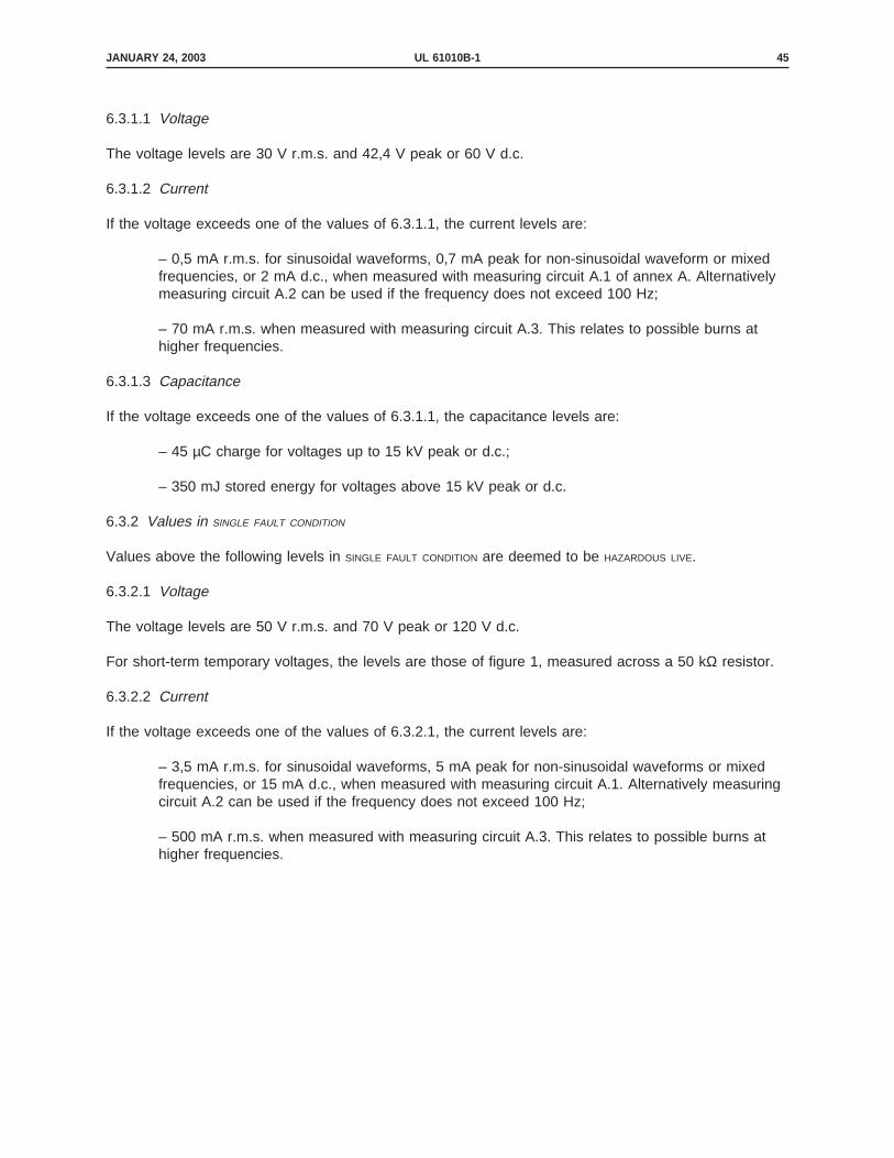
6.3.1.1 Voltage
The voltage levels are 30 V r.m.s. and 42,4 V peak or 60 V d.c.
6.3.1.2 Current
If the voltage exceeds one of the values of 6.3.1.1, the current levels are:
– 0,5 mA r.m.s. for sinusoidal waveforms, 0,7 mA peak for non-sinusoidal waveform or mixedfrequencies, or 2 mA d.c., when measured with measuring circuit A.1 of annex A. Alternativelymeasuring circuit A.2 can be used if the frequency does not exceed 100 Hz;
– 70 mA r.m.s. when measured with measuring circuit A.3. This relates to possible burns athigher frequencies.
6.3.1.3 Capacitance
If the voltage exceeds one of the values of 6.3.1.1, the capacitance levels are:
– 45 µC charge for voltages up to 15 kV peak or d.c.;
– 350 mJ stored energy for voltages above 15 kV peak or d.c.
6.3.2 Values in SINGLE FAULT CONDITION
Values above the following levels in SINGLE FAULT CONDITION are deemed to be HAZARDOUS LIVE.
6.3.2.1 Voltage
The voltage levels are 50 V r.m.s. and 70 V peak or 120 V d.c.
For short-term temporary voltages, the levels are those of figure 1, measured across a 50 kΩ resistor.
6.3.2.2 Current
If the voltage exceeds one of the values of 6.3.2.1, the current levels are:
– 3,5 mA r.m.s. for sinusoidal waveforms, 5 mA peak for non-sinusoidal waveforms or mixedfrequencies, or 15 mA d.c., when measured with measuring circuit A.1. Alternatively measuringcircuit A.2 can be used if the frequency does not exceed 100 Hz;
– 500 mA r.m.s. when measured with measuring circuit A.3. This relates to possible burns athigher frequencies.
JANUARY 24, 2003 UL 61010B-1 45

6.3.2.3 Capacitance
If the voltage exceeds one of the values of 6.3.2.1, the capacitance level is that of figure 2.This is generated text for figtxt.
JANUARY 24, 2003UL 61010B-146

Figur e 1 – Maximum duration of short-term temporary ACCESSIBLE voltages in SINGLE FAULT
CONDITION (see 6.3.2.1)
JANUARY 24, 2003 UL 61010B-1 47

Figur e 2 – Charged capacitance level in SINGLE FAULT CONDITION (see 6.3.2.3)
JANUARY 24, 2003UL 61010B-148

6.4 Protection in NORMAL CONDITION
ACCESSIBLE parts shall be prevented from becoming HAZARDOUS LIVE by one or more of the following means:
– BASIC INSULATION (see annex E);
– ENCLOSURES or BARRIERS;
– PROTECTIVE IMPEDANCE (see 6.5.3).
NOTE – Materials which can easily be damaged are not considered to provide suitable insulation, for example
lacquer, enamel, oxides, and anodic films. Non-impregnated hygroscopic materials such as paper, fibres and
fibrous materials are also not considered to provide suitable insulation.
ENCLOSURES and BARRIERS shall meet the rigidity requirements of 8.1. If ENCLOSURES or BARRIERS provideprotection by insulation, it shall meet the requirements of BASIC INSULATION.
CLEARANCES, CREEPAGE DISTANCES and insulation between ACCESSIBLE parts and HAZARDOUS LIVE parts shall meetthe requirements of 6.7 and the applicable requirements for BASIC INSULATION of annex D.
NOTES
1 CLEARANCES and CREEPAGE DISTANCES necessary for safety can be checked by measurement, except asspecified in D.7.
2 Solid insulation necessary for safety can be checked by applying the test voltage of annex Dappropriate to the working voltage. The thickness required for solid insulation can be determined fromthe test voltage it must withstand. Partial discharge testing may also be appropriate (see IEC 664).
3 Under mechanical or thermal stress conditions, insulation may have to be increased to meet therequirements of clauses 7, 8 and 9.
Compliance is checked:
– by the determination of 6.2;
– by the tests of 6.8 for dielectric strength of BASIC INSULATION;
– by the test of 8.1 for rigidity of ENCLOSURES and BARRIERS.
JANUARY 24, 2003 UL 61010B-1 49

6.5 Protection in SINGLE FAULT CONDITION
Additional protection shall be provided to ensure that ACCESSIBLE parts are prevented from becomingHAZARDOUS LIVE in SINGLE FAULT CONDITION. The protection shall consist of one or more of the protective meansspecified in 6.5.1 to 6.5.3, except as specified in 6.5.4, or by automatic disconnection of the supply in caseof a fault.
NOTES
1 Protective devices which automatically disconnect equipment from its supply source are normallypart of the building installation but can form part of the equipment.
2 Protective earthing (see 6.5.1) requires co-ordination of the type of system earthing, thecharacteristics of protective devices and the impedance of the earth path. For means of systemearthing and for automatic disconnection of the supply, see IEC 364-4-41, 413.1. However, if DOUBLE
INSULATION or REINFORCED INSULATION (see 6.5.2) is used throughout, co-ordination with the system or theinstallation is not required.
Compliance is checked as specified in 6.5.1 to 6.5.3.
6.5.1 Protective earthing
ACCESSIBLE conductive parts shall be bonded to the PROTECTIVE CONDUCTOR TERMINAL if they could becomeHAZARDOUS LIVE in case of a single fault of the primary protective means specified in 6.4. Alternatively, suchACCESSIBLE parts shall be separated from parts which are HAZARDOUS LIVE by a conductive protective screenor BARRIER bonded to the PROTECTIVE CONDUCTOR TERMINAL. For measuring and test equipment, indirect bondingis permitted as an alternative to direct bonding (see 6.5.1.4).
ACCESSIBLE conductive parts need not be bonded to the PROTECTIVE CONDUCTOR TERMINAL if they are separatedfrom all HAZARDOUS LIVE parts by DOUBLE INSULATION or REINFORCED INSULATION.
Compliance is checked by inspection.
6.5.1.1 PROTECTIVE BONDING
PROTECTIVE BONDING shall consist of directly connected structural parts or discrete conductors, or both. It shallwithstand all thermal and dynamic stresses to which it could be subjected before one of the overcurrentprotection means (see 9.6) disconnects the equipment from the supply (see also 6.11.2 h ii).
Compliance is checked by inspection and, when necessary, by measurement of the cross-sectional areaof bonding conductors.
JANUARY 24, 2003UL 61010B-150

6.5.1.2 Bonding impedance of plug-connected equipment
The impedance between the PROTECTIVE CONDUCTOR TERMINAL and each ACCESSIBLE part for which PROTECTIVE
BONDING is specified shall not exceed 0,1 Ω. Mains cord impedance does not form part of the specifiedbonding impedance.
Compliance is checked by applying a test current for 1 min and then calculating impedance. The testcurrent is the greater of:
– 25 A d.c. or a.c. r.m.s. at RATED mains frequency;
– a current equal to twice the RATED current of the equipment.
If the equipment contains overcurrent protection devices for all poles of the mains supply, and if the wiringbetween the supply and the overcurrent protection devices cannot become connected to ACCESSIBLE
conductive parts in the case of a single fault, the current for the bonding impedance measurement shallnot exceed twice the RATED current of the internal overcurrent protection devices.
6.5.1.3 Bonding impedance of PERMANENTLY CONNECTED EQUIPMENT
Bonding of PERMANENTLY CONNECTED EQUIPMENT shall be of low impedance.
Compliance is checked by applying a test current for 1 min between the PROTECTIVE CONDUCTOR TERMINAL andeach ACCESSIBLE conductive part for which PROTECTIVE BONDING is specified. The voltage between them shallnot exceed 10 V d.c. or a.c. r.m.s. The test current is twice the value of the overcurrent protection meansspecified in the installation instructions for the building supply mains circuit.
If the equipment contains overcurrent protection devices for all poles of the mains supply, and if the wiringbetween the supply and the overcurrent protection devices cannot become connected to ACCESSIBLE
conductive parts in the case of a single fault, the current for the bonding impedance measurement shallnot exceed twice the RATED current of the internal overcurrent protection devices.
6.5.1.4 Indirect bonding for measuring and test equipment
Indirect bonding established a connection between the PROTECTIVE CONDUCTOR TERMINAL and ACCESSIBLE
conductive parts when these become HAZARDOUS LIVE as a result of a fault. Devices to establish indirectbonding are:
a) Voltage limiting devices which become conductive when the voltage across them exceeds50 V r.m.s., 70 V peak, or 120 V d.c., with overcurrent protection to prevent breakdown of thedevice.
Compliance is checked by connecting the ACCESSIBLE conductive parts to the mains supplyTERMINALS while the equipment is connected to the mains supply as in NORMAL USE. The voltagebetween the ACCESSIBLE conductive parts and the PROTECTIVE CONDUCTOR TERMINAL shall not exceed50 V r.m.s., 70 V peak, or 120V d.c., for more than 0,2 s.
b) Voltage-sensitive tripping devices which interrupt all poles of the mains supply, and connectthe ACCESSIBLE conductive parts to the PROTECTIVE CONDUCTOR TERMINAL whenever the voltage acrossthem exceeds 50 V r.m.s., 70 V peak, or 120 V d.c.
JANUARY 24, 2003 UL 61010B-1 51

Compliance is checked by applying a voltage of 50 V r.m.s., 70 V peak, or 120 V d.c. betweenthe ACCESSIBLE conductive parts and the PROTECTIVE CONDUCTOR TERMINAL. The tripping action shalltake place within 0,2 s.
6.5.2 DOUBLE INSULATION and REINFORCED INSULATION
CLEARANCES and CREEPAGE DISTANCES forming part of DOUBLE INSULATION or REINFORCED INSULATION shall meet theapplicable requirements of annex D and shall pass the dielectric strength test of 6.8 (see annex E).ENCLOSURES shall meet the requirements of 6.9.2.
NOTES
1 CLEARANCES and CREEPAGE DISTANCES necessary for safety can be checked by measurement, except asspecified in D.7.
2 Solid insulation necessary for safety can be checked by applying the test voltage of annex Dappropriate to the working voltage. The thickness required for solid insulation can be determined fromthe test voltage it must withstand. Partial discharge testing may also be appropriate (see IEC 664).
3 Under mechanical or thermal stress conditions, insulation may have to be increased to meet therequirements of clauses 7, 8 and 9.
Compliance is checked as specified in 6.7, 6.8 and 6.9.2. The parts of DOUBLE INSULATION are testedseparately if this is possible; the tests for REINFORCED INSULATION are otherwise used.
6.5.3 PROTECTIVE IMPEDANCE
A PROTECTIVE IMPEDANCE shall be one or more of the following, so that ACCESSIBLE conductive parts cannotbecome HAZARDOUS LIVE as a result of a SINGLE FAULT CONDITION:
– an appropriate HIGH INTEGRITY single component (see 14.6);
– a combination of components;
– a combination of BASIC INSULATION and a current or voltage limiting device.
Components, wires and connections shall be RATED according to the requirements for both NORMAL CONDITION
and SINGLE FAULT CONDITION.
Compliance is checked by inspection and by the measurements of 6.3 in SINGLE FAULT CONDITION (see4.4.2.1).
JANUARY 24, 2003UL 61010B-152

6.5.4 Built-in panel meters
Panel meters built into equipment are not required to meet the requirements of 6.5.1 to 6.5.3 providedthat:
– the panel meter has no ACCESSIBLE conductive parts after building-in;
– ACCESSIBLE surfaces of the panel meter are separated from HAZARDOUS LIVE parts by at least BASIC
INSULATION;
– ACCESSIBLE surfaces of parts of panel meters intended to be grasped are separated fromHAZARDOUS LIVE parts by DOUBLE INSULATION or REINFORCED INSULATION.
NOTE – Although BASIC INSULATION is accepted for the time being as meeting the requirements of the standard, it is
intended that this relaxation will be withdrawn after a period for manufacturers to alter the design and production
of panel meters.
Compliance is checked by inspection and by dielectric strength test of the insulation.
6.6 External circuits
6.6.1 Separation of internal circuits
If an internal circuit which is not HAZARDOUS LIVE in NORMAL USE is intended for connection to an externalcircuit, separation shall be provided between this externally connected internal circuit and other internalcircuits, to prevent the external circuit from becoming HAZARDOUS LIVE in NORMAL CONDITION or SINGLE FAULT
CONDITION.
Circuits which do not exceed the values of 6.3.2 in NORMAL CONDITION and SINGLE FAULT CONDITION, and whichare ACCESSIBLE at external TERMINALS, shall be separated from other internal circuits having values abovethose of 6.3.1 in NORMAL CONDITION. BASIC INSULATION is sufficient if the other internal circuit does not exceedthe values of 6.3.2 in NORMAL CONDITION. If the values of 6.3.2 are exceeded in NORMAL CONDITION, one of thefollowing means shall be applied:
– DOUBLE INSULATION or REINFORCED INSULATION (see annex E);
– PROTECTIVE IMPEDANCE;
– BASIC INSULATION and protective screening (see annex E);
– BASIC INSULATION and PROTECTIVE BONDING, provided the protected circuit is of such low impedancethat it will not become HAZARDOUS LIVE in a SINGLE FAULT CONDITION of the other internal circuit (seeannex E).
Even if the other internal circuit exceeds the values of 6.3.2 in NORMAL CONDITION, BASIC INSULATION is sufficientif the TERMINAL (socket, connector, etc.) for the external circuit has no live parts which are ACCESSIBLE, andif the manufacturer’s instructions (see 5.4.3 and 5.4.4) include the following:
– a statement that the TERMINAL is for use only with equipment which has no live parts which areACCESSIBLE;
– the RATING of the insulation required for external circuits, making it clear that the insulationmust be suitable for SINGLE FAULT CONDITION;
JANUARY 24, 2003 UL 61010B-1 53

– the connection to be used at the remote end of external circuits;
– the type of equipment which may be connected to the TERMINAL, unless the specifiedconnection complies with or is specified by an IEC standard.
These requirements do not apply if short-circuiting between the two circuits could not cause the externalcircuit to become HAZARDOUS LIVE.
NOTE – Annex E gives the examples of circuits and the separation required between them; 9.1 and annex G give
additional requirements for the separation or circuits to prevent fire.
Compliance is checked by inspection and by the dielectric strength tests of 6.8.
6.6.2 TERMINALS for external circuits
ACCESSIBLE TERMINALS shall not be HAZARDOUS LIVE, except as permitted by 6.1.1.
NOTE – TERMINALS can contain one or several contacts (see 3.2.1) and the term therefore includes sockets,
connectors, etc.
The following TERMINALS shall not be HAZARDOUS LIVE and the exceptions of 6.1.1 do not apply:
– PROTECTIVE CONDUCTOR TERMINALS;
– FUNCTIONAL EARTH TERMINALS (measuring earth TERMINALS);
– TERMINALS for headphones.
TERMINALS which receive a charge from an internal capacitor shall not be HAZARDOUS LIVE 10 s afterinterruption of the supply. (also see 6.10.3)
TERMINALS which are energized from the interior, with HAZARDOUS LIVE VOLTAGE exceeding 1 kV r.m.s. or 1.5 kVd.c., or with floating voltage exceeding 1 kV r.m.s. or 1.5 kV d.c., shall not be ACCESSIBLE and the exceptionsof 6.1.1 shall not apply. Equipment with such TERMINALS shall be designed so that an ACCESSIBLE HAZARDOUS
LIVE voltage is not present when connectors are not mated, or a marking shall warn the OPERATOR of thepossible presence of an ACCESSIBLE HAZARDOUS LIVE voltage (see 5.2).
Compliance is checked by inspection, and by the determination of 6.2 and the measurements of 6.3.
JANUARY 24, 2003UL 61010B-154

6.6.3 Circuits with TERMINALS which are HAZARDOUS LIVE
These circuits shall not be connected to ACCESSIBLE conductive parts, except for circuits which are notmains circuits, and which are designed to be operated with one TERMINAL contact at earth potential. In suchcases the ACCESSIBLE conductive parts shall not be HAZARDOUS LIVE.
If such a circuit is also designed to be operated with one ACCESSIBLE TERMINAL contact (signal low) floatingat a voltage which is not HAZARDOUS LIVE, this TERMINAL contact is permitted to be connected to a commonFUNCTIONAL EARTH TERMINAL or system (for example a coaxial screening system). This common FUNCTIONAL
EARTH TERMINAL or system is also permitted to be connected to other ACCESSIBLE conductive parts.
Compliance is checked by inspection.
6.7 CLEARANCES and CREEPAGE DISTANCES
CLEARANCES and CREEPAGE DISTANCES between circuits and parts shall be at least those specified in annex D.The CLEARANCES and CREEPAGE DISTANCES specified in annex D do not apply to the inner layers of void-freemulti-layer printed circuit boards.
Compliance is checked by inspection and measurement. When determining a CLEARANCE or CREEPAGE
DISTANCE to ACCESSIBLE parts, the ACCESSIBLE surface of an insulating ENCLOSURE is considered to be conductiveas if it was covered by metal foil wherever it can be touched with a standard test finger (see annex B).
To simulate a possible reduction in CLEARANCE or CREEPAGE DISTANCE, the rigid test finger is used duringmeasurement to apply a force of 10 N to any point on bare conductors connected to TERMINALS and a forceof 30 N to the outside of ENCLOSURES.
6.7DV D2 Addition of the following:
6.7DV.1 The CLEARANCES and CREEPAGE DISTANCES between FIELD WIRING TERMINAL parts of oppositepolarity and between FIELD WIRING TERMINAL parts and the ENCLOSURE in PERMANENTLY CONNECTED
EQUIPMENT shall not be less than those specified in table 6.7DV.1.1.
6.7DV.2 Compliance with 6.7DV.1 is to be checked by first applying and removing a forceof 2 N against any wire or uninsulated part followed by measuring the applicable CLEARANCES
or CREEPAGE DISTANCES.
6.7DV.3 The requirement in 6.7DV.1 does not apply if it can be demonstrated that theCLEARANCESS and CREEPAGE DISTANCES of annex D can not be violated when evaluated per thecompliance statement to 6.11.1 (a).
Table 6.7DV.1.1 D2 Addition:
JANUARY 24, 2003 UL 61010B-1 55
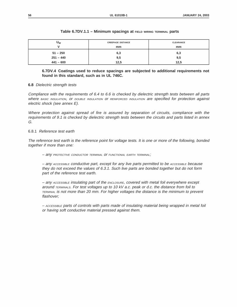
Table 6.7DV.1.1 – Minimum spacings at FIELD WIRING TERMINAL parts
UW CREEPAGE DISTANCE CLEARANCE
V mm mm
51 – 250 6,3 6,3
251 – 440 9,5 9,5
441 – 600 12,5 12,5
6.7DV.4 Coatings used to reduce spacings are subjected to additional requirements notfound in this standard, such as in UL 746C.
6.8 Dielectric strength tests
Compliance with the requirements of 6.4 to 6.6 is checked by dielectric strength tests between all partswhere BASIC INSULATION, or DOUBLE INSULATION or REINFORCED INSULATION are specified for protection againstelectric shock (see annex E).
Where protection against spread of fire is assured by separation of circuits, compliance with therequirements of 9.1 is checked by dielectric strength tests between the circuits and parts listed in annexG.
6.8.1 Reference test earth
The reference test earth is the reference point for voltage tests. It is one or more of the following, bondedtogether if more than one:
– any PROTECTIVE CONDUCTOR TERMINAL or FUNCTIONAL EARTH TERMINAL;
– any ACCESSIBLE conductive part, except for any live parts permitted to be ACCESSIBLE becausethey do not exceed the values of 6.3.1. Such live parts are bonded together but do not formpart of the reference test earth.
– any ACCESSIBLE insulating part of the ENCLOSURE, covered with metal foil everywhere exceptaround TERMINALS. For test voltages up to 10 kV a.c. peak or d.c. the distance from foil toTERMINAL is not more than 20 mm. For higher voltages the distance is the minimum to preventflashover;
– ACCESSIBLE parts of controls with parts made of insulating material being wrapped in metal foilor having soft conductive material pressed against them.
JANUARY 24, 2003UL 61010B-156

6.8.2 Humidity preconditioning
To ensure that equipment will not become hazardous in the humidity conditions of 1.4, it is subjected tohumidity preconditioning before the voltage tests of 6.8.4. The equipment is not operated duringpreconditioning.
If wrapping in foil is required by 6.8.1, the foil is not applied until after humidity preconditioning andrecovery.
Electrical components, covers, and other parts which can be removed by hand are removed andsubjected to the humidity preconditioning together with the main part.
Preconditioning is carried out in a humidity chamber containing air with a humidity of 92,5% r.h. ± 2,5%r.h. The temperature of the air in the chamber is maintained at 40°C ± 2°C.
Before applying humidity, the equipment is brought to a temperature of 42°C ± 2°C, normally by keepingit at this temperature for at least 4 h before the humidity preconditioning.
The air in the chamber is stirred and the chamber is designed so that condensation will not precipitate onthe equipment.
The equipment remains in the chamber for 48 h, after which it is removed and allowed a recovery periodof 2 h under the environmental conditions of 4.3.1, with the covers of non-ventilated equipment removed.
6.8.3 Conduct of tests
The tests specified in 6.8.4 are performed and completed within 1 h of the end of the recovery period afterhumidity preconditioning. The equipment is not operated during the tests.
Voltage tests are not made between two circuits, or between a circuit and an ACCESSIBLE conductive part,if they are connected to each other or not separated from each other.
PROTECTIVE IMPEDANCE in parallel with the insulation to be tested is disconnected.
Where two or more protective means are used in combination (see 6.5 and 6.6.1), the voltages specifiedfor DOUBLE INSULATION and REINFORCED INSULATION could be applied to parts of circuits which are not requiredto withstand these voltages. To avoid this, such parts may be disconnected during the tests, or the partsof circuits where DOUBLE INSULATION or REINFORCED INSULATION is required may be tested separately.
JANUARY 24, 2003 UL 61010B-1 57

6.8.4 Voltage tests
Voltage tests are applied, using the values specified in annex D. No breakdown or repeated flashovershall occur. Corona effects and similar phenomena are disregarded.
The a.c., d.c. and peak impulse tests are alternative test methods. It is sufficient that the equipmentpasses any one of the three. For example, a.c. may be chosen for simplicity, d.c. to avoid capacitivecurrents or the impulse test to reduce power dissipation in components.
Impulse tests are the 1,2/50 µs test specified in IEC 60, conducted for a minimum of 3 pulses of eachpolarity at 1 s minimum intervals.
The a.c. and d.c. tests are conducted with the voltage raised gradually over a period of 10 s or less to thespecified value so that no appreciable transients occur, then maintained for 1 min.
NOTES
1 When testing circuits, it may not be possible to separate tests of CLEARANCE from tests of solidinsulation.
2 The maximum test current of test equipment is usually limited to avoid hazards arising from the testand damage to equipment which fails the test.
3 It may be useful to make partial discharges within the insulation material perceptible (see IEC 270).
4 Care should be taken to discharge stored energy after test.
6.9 Constructional requirements for protection against electric shock
6.9.1 General
In circuits exceeding the values of 6.3.2 in NORMAL CONDITION or SINGLE FAULT CONDITION:
– the security of wiring connections subject to mechanical stresses shall not depend only onsoldering;
– screws securing removable covers shall be captive if their length determines a CLEARANCE orCREEPAGE DISTANCE between ACCESSIBLE conductive parts and HAZARDOUS LIVE parts.
– accidental loosening or freeing of the wiring, screws, etc., shall not cause ACCESSIBLE parts tobecome HAZARDOUS LIVE.
Compliance is checked by inspection.
JANUARY 24, 2003UL 61010B-158

6.9.2 ENCLOSURES of equipment with DOUBLE INSULATION or REINFORCED INSULATION
Equipment which relies on DOUBLE INSULATION or REINFORCED INSULATION for protection against electric shockshall have an ENCLOSURE which surrounds all metal parts. This requirement does not apply to small metalparts such as nameplates, screws or rivets, if they are separated from parts which are HAZARDOUS LIVE byREINFORCED INSULATION or its equivalent.
ENCLOSURES or parts of ENCLOSURES made of insulating material shall meet the requirements for DOUBLE
INSULATION and REINFORCED INSULATION.
Protection for ENCLOSURES or parts of ENCLOSURES made of metal shall be provided by one of the followingmeans, except for parts where PROTECTIVE IMPEDANCE is used:
– provision of an insulating coating or BARRIER on the inside of the ENCLOSURE. This shall surroundall metal parts and all places where loosening of a part which is HAZARDOUS LIVE might cause it totouch a metal part of the ENCLOSURE;
– ensuring that CLEARANCES and CREEPAGE DISTANCES between the ENCLOSURE and parts which areHAZARDOUS LIVE cannot be reduced below the values of tables D.1 to D.6 by loosening of parts orwires.
NOTE – Screws or nuts with lock washers are not regarded as liable to become loose, nor are wires which are
mechanically secured by more than soldering alone.
Compliance is checked by inspection and measurement, and by the tests of 6.8.
6.9.3 Equipment using PROTECTIVE BONDING
a) Where a part of the equipment is removable by the OPERATOR, the PROTECTIVE BONDING (see6.5.1.1) for the remainder of the equipment shall not be interrupted (except when that part alsocarries the mains input connection to the whole equipment).
b) Movable conductive connections, for example, hinges, slides, etc., shall not be the solePROTECTIVE BONDING path unless they are specifically designed for electrical interconnection andmeet the requirements of 6.5.1.
c) The exterior metal braid of cables, even if connected to the PROTECTIVE CONDUCTOR TERMINAL,shall not be regarded as PROTECTIVE BONDING.
d) When power from the mains supply is passed through equipment for use by otherequipment, means shall also be provided for passing the protective conductor through theequipment to protect the other equipment. The impedance of the protective conductor paththrough the equipment shall not exceed that specified in 6.5.1.2.
e) Protective earthing conductors may be bare or insulated. Insulation shall be green/yellow,except in the following cases:
– for earthing braids, either green/yellow or transparent;
– for internal protective conductors in assemblies such as ribbon cables, busbars,flexible printed wiring, etc., any colour may be used provided that no hazard is likely toarise from non-identification of the protective conductor.
JANUARY 24, 2003 UL 61010B-1 59

f) Equipment using PROTECTIVE BONDING shall be provided with a TERMINAL meeting therequirements of 6.11.2 and suitable for connection to a protective conductor.
NOTE – Metal structural parts of the equipment may be used to provide continuity of PROTECTIVE BONDING.
Compliance is checked by inspection.
6.9.3DV DR Modification by adding the following after the last dash in part (e):
– Green insulation without yellow stripes is acceptable.
6.9.4 Over-range indication
If a hazard (see 1.2) could arise from an OPERATOR’S reliance on the value (for example the voltage) of aquantity displayed by the equipment, the display shall give an unambiguous indication whenever the valueis above the maximum positive value or below the minimum negative value of the range to which theinstrument is set.
NOTE - Examples of hazardous indications include any of the following which do not have a separate
unambiguous indication of an over-range value:
a) analogue meters with stops at the exact ends of the range;
b) digital meters which show a low value when the true value is above the range maximum (for example 1 001,5
V displayed as 001,5 V);
c) chart recorders which print a trace at the edge of the chart, thus indicating a value at the range maximum when
the true value is higher.
Compliance is checked by inspection and, in cases of doubt, by provoking an over-range value.
6.10 Connection to mains supply source and connections between parts of equipment
6.10.1 Mains supply cords
The following requirements apply to non-detachable mains supply cords and to detachable mains supplycords supplied with the equipment:
– mains supply cords shall be RATED for the maximum current for the equipment and the cableused shall meet the requirements of IEC 227 or IEC 245. Mains supply cords certified orapproved by any recognized national test house are regarded as meeting this requirement;
– if a cord is likely to contact hot external parts of the equipment, it shall be made of suitablyheat-resistant material (see also 5.4.5);
– when a detachable cords is used, both the cord and the appliance inlet shall have at least thehighest temperature RATING required for either part;
NOTE – The requirement for an equal temperature RATING for both the cord and the appliance inlet
ensures that cord sets of low-temperature RATING cannot be used inadvertently.
– green/yellow covered conductors shall be used only for connection to PROTECTIVE CONDUCTOR
TERMINALS;
JANUARY 24, 2003UL 61010B-160

Detachable mains supply cords with mains connectors according to IEC 320 shall either comply with therequirements of IEC 799, or shall be RATED at least for the current RATING of the mains connector which isfitted to the cord.
The terminology for mains supply cords is given in figure 3.
Compliance is checked by inspection and, where necessary, by measurement.
6.10.1DV DC Addition of the following to identify United States standards for mainscords:
6.10.1DV.1 Requirements for mains cords or cord sets are contained in UL 817.
6.10.1DV.2 Requirements for general use receptacles, attachment plugs, and similar wiringdevices are contained in UL 498.
This is generated text for figtxt.
JANUARY 24, 2003 UL 61010B-1 61

Figur e 3 – Detachable mains supply cords and connections
1 Appliance coupler
2 Appliance inlet
5 Detachable power supply cord
6 Equipment
7 Fixed mains socket-outlet
8 Mains connector
9 Mains plug
JANUARY 24, 2003UL 61010B-162

6.10.2 Fitting of non-detachable mains supply cords
6.10.2.1 Cord entry
Non-detachable mains supply cords shall be protected against abrasion and sharp bends at the pointwhere the cord enters the equipment, by one of the following means:
– an inlet or bushing with a smoothly-rounded bell-mouthed opening with a radius of curvatureat least one and a half times the overall diameter of a cord with the largest cross-sectional areawhich can be fitted;
– a reliably-fixed cord guard made of insulating material protruding beyond the inlet opening byat least five times the overall diameter of a cord with the largest cross-sectional area which canbe fitted. For flat cords the major overall cross-sectional dimension is taken as the overalldiameter.
Compliance is checked by inspection and measurement, and by the dielectric strength test of 6.8.4 (whereapplicable). In case of doubt, cord guards are checked by the following test, which is performed in anambient temperature of 23°C ± 2°C, using the cord fitted by the manufacturer: A mass of 10 D2 g isattached to the free end of the cord, where D is the overall diameter of a round cord or the minor overalldimension of a flat cord. Flat cords are bent in the place of least resistance. Immediately after the masshas been attached, the radius of curvature of the center-line of the cord shall nowhere be less than 1,5D.
Equipment shall be in the position of NORMAL USE, except that for HAND-HELD EQUIPMENT and equipmentintended to be moved while in operation, the test is carried out with axis of the cord guard, where the cordleaves it, at an angle of 45° above the horizontal.
6.10.2.2 Cord anchorage
The cord anchorage shall relieve the conductors of the cord from strain, including twisting, where they areconnected within the equipment, and shall protect the insulation of the conductors from abrasion. Theprotective earth conductor, if any, shall be the last to take the strain if the cord slips in its anchorage.
Cord anchorages shall meet the following requirements:
– the cord shall not be clamped by a screw which bears directly on the cord;
– knots in the cord shall not be used;
– it shall not be possible to push the cord into the equipment to an extent which could cause ahazard;
– failure of the cord insulation in a cord anchorage which has metal parts shall not causeACCESSIBLE conductive parts to become HAZARDOUS LIVE;
– a compression bushing shall not be used as a cord anchorage unless it has provision forclamping all types and sizes of mains supply cords which meet the requirements of 6.10.1 andare suitable for connection to the TERMINALS provided, or the bushing has been designed toterminate a screened mains supply cord;
– the cord anchorage shall be designed so that cord replacement does not cause a hazard andit shall be clear how the relief from strain is provided.
JANUARY 24, 2003 UL 61010B-1 63

Compliance is checked by inspection and the following push-pull test: the cord is pushed into theequipment manually, as far as possible. It is then subjected 25 times to a steady pull of the value shownin table 2, applied for 1 s each time in the least favourable direction. Immediately afterwards it is subjectedfor 1 min to a torque of the value shown in table 2.
Table 2 – Physical test on power supply cords
Mass (M) of equipment Pull Torque
kg N N•m
M ≤ 1 30 0,10
1 < M ≤ 4 60 0,25
4 < M 100 0,35
After the tests:
– the cord shall not have been damaged;
– the cord shall not have been displayed longitudinally by more than 2 mm;
– there shall be no signs of strain at the point where the anchorage clamps the cable;
– CLEARANCES and CREEPAGE DISTANCES shall not have been reduced below the applicable values ofannex D.
6.10.3 Plugs and connectors
a) Plugs and connectors for connecting equipment to the mains supply, including appliancecouplers used to connect detachable mains supply cords to the equipment, shall comply withthe relevant specifications for plugs, socket-outlets and connectors.
b) If the equipment is designed to be supplied only at voltages below the level of 6.3.2.1 inNORMAL CONDITION or SINGLE FAULT CONDITION, or from a source used solely to supply that equipment,the plugs of the mains supply cord shall not fit into the socket-outlets of mains supply systemsat voltages above the RATED supply voltage of the equipment. Mains-type plugs and socketsshall not be used for purposes other than connection of a mains supply.
c) If plug pins of cord-connected equipment receive a charge from an internal capacitor, thepins shall not be HAZARDOUS LIVE 5 s after disconnection of the supply.
d) On equipment with accessory mains socket-outlets:
– if the outlet can accept a standard mains supply plug, there shall be a markingaccording to 5.1.3 e);
– If the outlet has a TERMINAL contact for a protective earth conductor, the input mainssupply connection to the equipment shall include a protective earth conductorconnected to a PROTECTIVE CONDUCTOR TERMINAL.
Compliance is checked by inspection. For plugs receiving a charge from an internal capacitor, themeasurements of 6.3 are made to establish that the levels of 6.3.1.3 are not exceeded.
JANUARY 24, 2003UL 61010B-164

6.10.3DV D2 Addition of the following to identify United States standards for mainsconnectors:
Requirements for plugs of mains cords are contained in UL 498.
6.10.4DV D2 Addition of 6.10.4DV.1 through 6.10.4DV.6.5.1 for PERMANENTLY CONNECTED
EQUIPMENT:
6.10.4DV.1 General
6.10.4DV.1.1 Equipment intended for permanent connection to the mains shall haveprovision for connection of a wiring system in accordance with the National ElectricalCode, NFPA 70.
6.10.4DV.1.2 Compliance with 6.10.4DV.1.1 is to be checked by inspection.
6.10.4DV.1.3 PERMANENTLY CONNECTED EQUIPMENT shall be provided with TERMINALS or leads for theconnection of conductors having an ampacity that, in accordance with the NationalElectrical Code, is acceptable for the equipment.
6.10.4DV.1.4 Compliance with 6.10.4DV.1.3 is to be checked by inspection.
6.10.4DV.2 Wiring TERMINALS
6.10.4DV.2.1 A TERMINAL or splice compartment shall be complete – that is, the top, all sides,and a complete bottom are provided when the equipment is shipped from the factory – andshall enclose all FIELD WIRING TERMINALS and splices intended to be made in the field.
6.10.4DV.2.2 Equipment with an ENCLOSURE that is complete need not be provided with aseparate compartment.
6.10.4DV.2.3 The TERMINAL or splice compartment in which mains connections to PERMANENTLY
CONNECTED EQUIPMENT are made shall be located so that:
– internal wiring and electrical components are not exposed to mechanicaldamage or strain while connections are being made, and
– these connections may be readily inspected after the equipment is installed asintended.
6.10.4DV.2.4 A wiring TERMINAL shall be provided in which connection is made by means ofscrews, nuts or equally effective devices.
6.10.4DV.2.5 Wire binding screws are permitted as follows:
– A No. 6 or M4 screw may be used to connect a 14 AWG (2,1 sq mm) or smallerwire.
– A No. 8 or M4.5 screw may be used to connect a 12 AWG (3,3 sq mm) orsmaller wire.
– A No. 10 or M5 screw may be used to connect a 10 AWG (5,3 sq mm) or smallerwire.
JANUARY 24, 2003 UL 61010B-1 65

6.10.4DV.2.6 Compliance with the requirements in this Clause is checked by inspection.
6.10.4DV.3 Leads
6.10.4DV.3.1 The free length of a lead inside a wiring compartment shall be at least 6inches (150 mm).
6.10.4DV.3.2 Compliance with 6.10.4DV.3.1 is checked by inspection.
6.10.4DV.4 TERMINAL and lead identification
6.10.4DV.4.1 TERMINALS and leads shall be identified in a manner that will permit theequipment to be connected as intended by the manufacturer. Equipment containing eithera mains-connected polarized convenience receptacle or a mains-connected polarized lampsocket must have an identified neutral (grounded) conductor.
6.10.4DV.4.2 A FIELD WIRING TERMINAL that is intended solely for connection of the neutral(grounded) mains conductor shall be readily distinguishable from all other TERMINALS. It shallbe constructed of, or plated with, metal that is substantially white in color.
6.10.4DV.4.3 The neutral (grounded) TERMINAL need not be white in color if it can be clearlyidentified in some other manner – such as on a wiring diagram permanently attached to theequipment.
6.10.4DV.4.4 A lead intended solely for field wiring connection to the neutral (grounded)mains conductor shall be readily distinguishable from all other leads by means of it beingfinished to show a white or natural gray color.
6.10.4DV.4.5 The protective grounding (earthing) TERMINAL shall be marked in accordancewith 5.1.6 (b).
6.10.4DV.4.6 The requirement in 6.10.4DV.4.5 is not required if markings such as ″G,″ ″GR,″″GND,″ ″GRD,″ ″GROUND,″ or ″GROUNDING″ are used.
6.10.4DV.4.7 The requirement in 6.10.4DV.4.5 is not required if a TERMINAL provided with agreen colored screwhead that is hexagonal, slotted, or both is used.
6.10.4DV.4.8 A lead intended for field connection to the protective grounding conductorshall be readily distinguishable from all other leads by being finished to show a greencolor with or without one or more yellow stripes.
6.10.4DV.4.9 Compliance with the requirements in this Clause is checked by inspection.
JANUARY 24, 2003UL 61010B-166
6.10.4DV.5 ENCLOSURE requirements for conduit entry
6.10.4DV.5.1 An ENCLOSURE shall not pull apart or sustain damage such as cracking andbreaking, and knockouts shall remain in place when subjected to pulling, torque, andbending, which are likely to occur.
6.10.4DV.5.2 ENCLOSURES having sheet metal members with a thickness no less than 0,81mm if of uncoated sheet steel, no less than 0,86 mm if of galvanized sheet steel, no lessthan 1,11 mm if of sheet aluminum, and no less than 1,09 mm if of sheet copper or sheetbrass are presumed to pass these tests.
6.10.4DV.5.3 Compliance with the requirements in this Clause is checked by performingthe tests of 6.10.4DV.6.
6.10.4DV.6 Conduit ENCLOSURE entry tests
6.10.4DV.6.1 General
6.10.4DV.6.1.1 After each of the tests in 6.10.4DV.6.2 – 6.10.4DV.6.5, the equipment mustmeet the criteria defined in 6.10.4DV.5.
6.10.4DV.6.2 Conduit pull-out test
6.10.4DV.6.2.1 The ENCLOSURE is to be suspended by a length of rigid conduit installed inone wall of the ENCLOSURE or mounted as intended in service, and a pulling force of 200 lbs(890 N) is to be applied for 5 min to a length of conduit installed in the opposite wall (orwall with conduit entry if ENCLOSURE is mounted rather than suspended).
6.10.4DV.6.3 Conduit torque test
6.10.4DV.6.3.1 The ENCLOSURE is to be securely mounted as intended in service. A torque inaccordance with table 6.10.4DV.6.3.1.1 is to be applied to a length of installed conduit in adirection tending to tighten the connection. The lever arm is to be measured from thecenter of the conduit.
Table 6.10.4DV.6.3.1.1 D2 Addition:
JANUARY 24, 2003 UL 61010B-1 67

Table 6.10.4DV.6.3.1.1 – Tightening torque for conduit
Trade size of conduit, Tightening torque,
in lb-in (N•m)
3/4 and smaller 800 (90,4)
1, 1-1/4, 1-1/2 1000 (113)
2 and larger 1600 (181)
6.10.4DV.6.3.2 An end-of-line ENCLOSURE – an ENCLOSURE that is intended to be connected atthe end of a run of conduit and has only one 3/4-in maximum trade size opening for theconnection of conduit – need only be subjected to a tightening torque of 200 lb-in (22,6N•m).
6.10.4DV.6.4 Bending
6.10.4DV.6.4.1 A length of conduit at least 1 ft (300 mm) long of the intended size is to beinstalled:
1) in the center of the largest unreinforced surface, or
2) in a hub or an opening if provided as part of the ENCLOSURE.
The ENCLOSURE is to be securely mounted as intended in service, but positioned sothat the installed conduit extends in a horizontal plane. A weight is to besuspended from the end of the conduit to produce the bending moment specifiedin Table 6.10.4DV.6.4.1.1. The magnitude of the weight is to be determined fromthe equation:
W = (M-0,5*C*L)/L
In which:
W is the weight, in lb, to be hung at the end of the conduit;
L is the length of the conduit, in inches, from the wall of the ENCLOSURE to the pointat which the weight is suspended;
C is the weight of the conduit, in lb; and
M is the bending moment required in lb-in.
For the SI system of units, the equation is
W = (0,1*M-0,5*C*L)/L
In which:
W and C are measured in kg;
M is measured in N•m; and
JANUARY 24, 2003UL 61010B-168

L is measured in m.
Table 6.10.4DV.6.4.1.1 D2 Addition:
Table 6.10.4DV.6.4.1.1 – Bending moment for conduit openings
Normal mounting planeof ENCLOSURE surface(a)
Conduit size, in Bending moment (b,c) lb-in (N•m)
Metallic conduit Nonmetallic conduit
Horizontal All 300 (34) 300 (34)
Vertical 1/2-3/4 300 (34) 300 (34)
1-up 600 (68) 300 (34)
6.10.4DV.6.4.2 If the ENCLOSURE surface may be installed in either a horizontal or a verticalplane, the vertical bending moment value is to be used.
6.10.4DV.6.4.3 The test procedure may be terminated prior to attaining the values specifiedif the deflection of the conduit exceeds 10 in (250 mm) for a 10 ft (3,05 m) length of conduit.
6.10.4DV.6.4.4 For an end-of-line ENCLOSURE as defined in clause 6.10.4DV.6.3.2, the bendingmoment is to be 150 lb-in (17,0 N•m).
6.10.4DV.6.5 Knockouts
6.10.4DV.6.5.1 A knockout is to be subjected to a force of 20 lb (89 N) applied at rightangles by means of a mandrel with a 1/4-in (6,4-mm) diameter flat end. The mandrel is tobe applied at the point most likely to cause movement of the knockout.
6.11 TERMINALS
6.11.1 ACCESSIBLE TERMINALS
a) ACCESSIBLE TERMINALS for flexible cords shall be located or shielded so that there is no risk ofaccidental contact between HAZARDOUS LIVE parts of different polarity or between such parts andother conductive parts, even if a strand of a conductor escapes from a TERMINAL. Unless it is self-evident (which is preferable) ACCESSIBLE TERMINALS shall be marked to show whether or not theyare connected to ACCESSIBLE conductive parts (see 5.1.6 c).
Compliance is checked by inspection after fully inserting a stranded conductor with an 8 mmlength of insulation removed, with one of the strands free. The stand shall not touch parts ofdifferent polarity or ACCESSIBLE conductive parts, when bent in every possible direction, withouttearing back the insulation or making sharp bends round BARRIERS.
b) ACCESSIBLE TERMINALS of circuits carrying HAZARDOUS LIVE voltage or current shall be anchored,fitted or designed so that they will not work loose when they are tightened, loosened or whenconnections are made.
Compliance is checked by manual test and inspection.
JANUARY 24, 2003 UL 61010B-1 69

6.11.2 PROTECTIVE CONDUCTOR TERMINAL
a) The integral protective conductor connection of an appliance inlet shall be regarded as thePROTECTIVE CONDUCTOR TERMINAL.
b) For equipment provided with a rewireable flexible cord and for PERMANENTLY CONNECTED
EQUIPMENT, the PROTECTIVE CONDUCTOR TERMINAL shall be located close to the mains supply TERMINALS.
c) If the equipment does not require connection to a mains supply, but nevertheless has acircuit or part which is required to be protectively earthed, the PROTECTIVE CONDUCTOR TERMINAL shallbe located near to the TERMINALS of that circuit for which protective earthing is necessary. If thiscircuit has external TERMINALS, the PROTECTIVE CONDUCTOR TERMINAL shall also be external.
d) PROTECTIVE CONDUCTOR TERMINALS for mains circuits shall be a least equivalent in current-carryingcapacity to the mains supply TERMINALS.
e) Soldered connections subject to mechanical stress shall be mechanically securedindependently from the soldering. Such connections shall not be used for other purposes suchas fixing constructional parts. Screw connections shall be secured against loosening.
f) The contact surfaces of PROTECTIVE CONDUCTOR TERMINALS shall be metal.
NOTE – Materials of protective conductor systems should be chosen to minimize the likelihood of
electro-chemical corrosion between the TERMINAL and the copper of the protective conductor, or any other
metal in contact with them.
g) Plug-in type PROTECTIVE CONDUCTOR TERMINALS combined with other TERMINALS and intended to beconnected and disconnected by hand, for example plugs and appliance couplers for mainscords or connector assemblies of plug-in units, shall be designed so that the protectiveconductor connection makes first and breaks last with respect to the other connections.
h) For equipment in which the protective conductor is required for protection against a SINGLE
FAULT CONDITION in a measuring circuit, the following shall apply:
i) the PROTECTIVE CONDUCTOR TERMINAL and protective conductor (including any indirectbonding) shall have at least the current RATING of the measuring TERMINALS;
ii) the PROTECTIVE BONDING shall not be interrupted by the presence of any switching orinterrupting device, except that devices used for indirect bonding in measuring and testequipment (6.5.1.4) are permitted to be part of the PROTECTIVE BONDING.
Compliance is checked by inspection.
JANUARY 24, 2003UL 61010B-170

6.11.3 FUNCTIONAL EARTH TERMINALS
FUNCTIONAL EARTH TERMINALS (measuring earth TERMINALS), if any, shall allow a connection which is independentof the protective conductor.
NOTE – Equipment may be equipped with FUNCTIONAL EARTH TERMINALS , irrespective of the protective means taken.
Compliance is checked by inspection
6.12 Disconnection from supply source
6.12.1 General
Except as specified in 6.12.1.1, equipment shall be provided with a means for disconnecting it from eachoperating energy supply source, whether external or internal to the equipment. The disconnecting meansshall disconnect all current-carrying conductors.
NOTE – Equipment may also be provided with a switch or other disconnecting device for functional purposes.
Compliance is checked as specified in 6.12.1.1 to 6.12.3.
6.12.1DV D2 Addition of requirement for maintaining polarity:
A line-connected single-pole switch, the center contact of a lampholder, and an automaticcontrol with a marked off position shall be connected to a TERMINAL or lead intended forconnection to the ungrounded conductor of the supply circuit.
6.12.1.1 Exceptions
A disconnecting device is not required if a short-circuit or overload cannot cause a hazard in the sense ofthis Part 1. Examples include:
– equipment intended for supply only from a low-energy source such as a small battery;
– equipment intended only for connection to an impedance-protected supply. Such a supply isone having an impedance of such value that, when the equipment is subjected to an overloador short circuit, the RATED supply conditions are not exceeded and no hazard can arise in thesense of this Part 1;
– equipment which constitutes an impedance-protected load. Such a load is a componentwithout discrete over current or thermal protection, and of such impedance that the RATING is notexceeded when the circuit of which the component is a part is subjected to an overload or shortcircuit.
Compliance is checked by inspection. In case of doubt a short circuit or overload is applied to check thatno hazard can arise.
JANUARY 24, 2003 UL 61010B-1 71

6.12.2 Requirements according to type of equipment
6.12.2.1 PERMANENTLY CONNECTED EQUIPMENT
PERMANENTLY CONNECTED EQUIPMENT and multi-phase equipment shall employ a switch or circuit breaker as themeans for disconnection.
Where a switch is not part of the equipment, documentation for equipment installation (see 5.4.3) shallspecify that:
– a switch or circuit-breaker shall be included in the building installation;
– it shall be in close proximity to the equipment and within easy reach of the OPERATOR;
– it shall be marked as the disconnecting device for the equipment.
Compliance is checked by inspection.
6.12.2.2 Single-phase cord-connected equipment
Single-phase cord-connected equipment shall have one of the following as a disconnecting device:
– a switch or circuit breaker;
– an appliance coupler which can be disconnected without the use of a TOOL;
– a separable plug, without a locking device, to mate with a socket-outlet in the building.
Compliance is checked by inspection.
6.12.2.3 Hazards arising from function
Equipment whose function may give rise to a hazard shall have an emergency switch, which need notdisconnect auxiliary circuits (such as cooling) which are necessary for safety.
Equipment having a ACCESSIBLE moving parts which could cause a hazard shall have an emergency switchfor disconnection which shall not be more than 1 m from the moving part.
Compliance is checked by inspection.
JANUARY 24, 2003UL 61010B-172

6.12.3 Disconnecting devices
If a disconnecting device is part of the equipment, it shall be located electrically as close as practicable tothe supply. Power-consuming components shall not be electrically located between the supply source andthe disconnecting device.
Electromagnetic interference suppression circuits are permitted to be located on the supply side of thedisconnecting device.
Compliance is checked by inspection.
6.12.3.1 Switches and circuit-breakers
An equipment switch or circuit-breaker employed as a disconnecting device shall meet the relevantrequirements of IEC 947-1 and IEC 947-3.
The relevant parts of IEC 947-3 include those requirements which relate to contact separation and toensuring that it is always evident whether the contacts are open or closed when the indicator is in the ″off″position.
If a switch or a circuit-breaker is used as a disconnecting device, it shall be marked to indicate thisfunction. If there is only one device – one switch or one circuit-breaker – symbols 9 and 10 of table 1 aresufficient.
A switch shall not be incorporated in a mains supply cord.
A switch or circuit-breaker shall not interrupt any protective earth conductor.
A switch or circuit-breaker with contacts for disconnecting and other contacts for other purposes shallcomply with the requirements of 6.6 and 6.7 for separation between circuits.
Compliance is checked by inspection.
6.12.3.2 Appliance couplers and plugs
If an appliance coupler or separable plug is used as the disconnecting device (see 6.12.2.2), it shall bereadily identifiable and easily reached by the OPERATOR (see 5.4.4, second dash). For single-phasePORTABLE EQUIPMENT, a plug on a cord of length not greater than 3 m is considered to be easily reached.
The protective earth conductor of an appliance coupler shall be connected before than supply conductorsand disconnected after them.
Compliance is checked by inspection.
7 Protection against mechanical hazards
7.1 General
Handling during NORMAL USE shall not lead to a hazard.
Protection against expelled parts shall be provided in SINGLE FAULT CONDITION.
JANUARY 24, 2003 UL 61010B-1 73

NOTE – All easily touched edges, projections, corners, openings, guards, handles and the like of the equipment
ENCLOSURE, should be smooth and rounded so as not to cause injury during NORMAL USE of the equipment.
Compliance is checked as specified in 7.2 to 7.5.
7.2 Moving parts
Moving parts shall not be able to crush, cut or pierce parts of the body of an OPERATOR likely to contactthem, nor severely pinch the OPERATOR’S skin.
This requirement does not apply to easily touched moving parts which are obviously intended to operateon parts or materials external to the equipment, for example drilling and mixing equipment. Suchequipment should be designed to minimize inadvertent touching of such moving parts (e.g. by fitting ofguards, handles, etc.)
If, during routine maintenance outside NORMAL USE, it is unavoidable for technical reasons that an OPERATOR
has to perform a function, such as adjustment, which requires access to hazardous moving parts, accessis permitted if all of the following precautions have been taken:
a) access to moving parts is not possible without the use of a TOOL;
b) the instructions for the RESPONSIBLE BODY include a statement that OPERATORS must be trainedbefore being allowed to perform the hazardous operation;
c) there are warning markings on any covers or parts which have to be removed to obtainaccess, and the warning prohibits access by untrained OPERATORS. As an alternative, symbol 14shall be placed on the covers or parts, with the warnings included in the documentation.
Compliance is checked by inspection.
7.3 Stability
Equipment and assemblies of equipment not secured to the building structure before operation shall bephysically stable in NORMAL USE.
If means are provided to ensure that stability is maintained after the opening of drawers, etc. by anOPERATOR, either these means shall be automatic or there shall be warning marking complying with 5.2.
Compliance is checked by carrying out each of the following tests independently (where relevant), duringwhich the equipment shall not overbalance. Containers contain the RATED amount of substance to providethe least favourable conditions of NORMAL USE. Castors are in their least favourable position of NORMAL USE.Doors, drawers, etc. are closed unless otherwise specified:
– equipment other than HAND-HELD EQUIPMENT, is tilted in each direction to an angle of 10° from itsnormal position;
– equipment which has both a height of 1 m or more and a mass of 25 kg or more, and allfloor-standing equipment, has a force applied at its top, or at a height of 2 m if the equipmenthas a height more than 2 m. The force is 250 N, or 20% of the mass of the equipment,whichever is less, and is applied in all directions except upwards. Jacks used in NORMAL USE, anddoors, drawers, etc., intended to be opened by an OPERATOR, are in their least favourableposition;
JANUARY 24, 2003UL 61010B-174

– floor-standing equipment has a force of 800 N applied downwards at the point of maximummoment to:
• all horizontal working surfaces;
• other surfaces providing an obvious ledge and which are not more than 1 m abovefloor level.
7.4 Provisions for lifting and carrying
Where carrying handles or grips are supplied with the equipment they shall be capable of withstanding aforce of four times the mass of the equipment.
Equipment of parts having a weight of 18 kg or more shall be provided with a means for lifting andcarrying, or directions shall be given in the manufacturer’s documentation.
Compliance is checked by inspection and the following test:
A single handle or grip is subjected to a force corresponding to four times the mass of the equipment. Theforce is applied uniformly over a 7 cm width at the center of the handle or grip, without clamping. The forceis steadily increased so that the test value is attained after 10 s and maintained for a period of 1 min.
If more than one handle or grip is fitted, the force is distributed between the handles or grips in the sameproportion as in NORMAL USE. If the equipment is fitted with more than one handle or grip but so designedthat it may readily be carried by only one handle or grip, each handle or grip shall be capable of sustainingthe total force.
The handles or grips shall not break loose from the equipment and there shall not be any permanentdistortion, cracking or other evidence of failure.
7.5 Expelled parts
Equipment shall contain or limit the energy of parts which might cause a hazard if expelled in the eventof a fault.
The means of protection against expelled parts shall not be removable without the aid of a TOOL.
Compliance is checked by inspection after fault testing as specified in 4.4.4.4.
8 Mechanical resistance to shock and impact
Equipment shall not cause a hazard when subjected to shock, vibration and impact likely to occur inNORMAL USE. To achieve this requirement, equipment shall have adequate mechanical strength,components shall be reliably secured and electrical connections shall be secure.
Compliance is checked by performing the tests of 8.1 to 8.3 and, except for FIXED EQUIPMENT, the appropriatetest of 8.4. The equipment is not operated during the tests. Glass parts which do not form part of anENCLOSURE are not subjected to the tests of 8.1 or 8.2 and are removed before the test of 8.4, if this ispossible.
After the completion of the tests, the equipment shall pass the voltage tests of 6.8.4 and is inspected tocheck that:
JANUARY 24, 2003 UL 61010B-1 75

– parts which are HAZARDOUS LIVE have not become ACCESSIBLE;
– ENCLOSURES show no cracks which could cause a hazard;
– CLEARANCES are not less than their permitted values and the insulation of internal wiringremains undamaged;
– BARRIERS have not been damaged or loosened;
– no moving parts are exposed, except as permitted by 7.2;
– there has been no damage which could cause spread of fire.
Damage to the finish, small dents which do not reduce CREEPAGE DISTANCES or CLEARANCES below the valuesspecified in this Part 1, and small chips which do not adversely affect the protection against electric shockor moisture, are to be ignored. Breakage of glass parts which are not part of the ENCLOSURE is ignored.
8.1 Rigidity test
The equipment is held firmly against a rigid support and subjected to a force of 30 N applied by thehemispherical end of a hard rod of 12 mm diameter. The rod is applied to any part of the ENCLOSURE whichis ACCESSIBLE when the equipment is ready for use, and which could cause a hazard if distorted, includingany part of the bottom of PORTABLE EQUIPMENT.
For equipment with non-metallic ENCLOSURES, this test if performed at an ambient temperature of 40° C (see10.1).
8.2 Impact hammer test
Bases, covers, etc., intended to be removed and replaced by the OPERATOR have their fixing screwstightened with the torque applied in NORMAL USE. The equipment is then held firmly against a rigid supportand tested with the impact hammer specified in IEC 68-2-63 (see annex C). The hammer nose is pressedperpendicularly against the surface of all external parts which are ACCESSIBLE in NORMAL USE and which areACCESSIBLE or NORMAL USE and which would be likely to cause a hazard if broken.
Three blows with an energy of 0,5 J are applied to each part.
Windows of panel-mounted indicating or recording instruments, which are part of a fixed installation, areexcluded from this test.
8.2DV D2 Addition:
Any test apparatus which imparts the same energy levels using the same design at theimpact surface is acceptable. Critical design parameters are the radius and material of theimpact surface and the mass of the body imparting the impact.
JANUARY 24, 2003UL 61010B-176

8.3 Not used.
8.4 Drop test
8.4.1 Equipment other than HAND-HELD EQUIPMENT
The tests shall be carried out as follows:
a) for equipment with a mass up to 20 kg, a corner drop test (see 8.4.1.1 and clause 3.2.2 ofIEC 68-2-31);
b) for equipment with a mass over 20 kg, a face drop test (see 8.4.1.2 and clause 3.2.1 of IEC68-2-31).
NOTE – If the equipment consists of two or more units, the value for the mass refers to the mass of each
individual unit. However, if one or more units are intended to be attached to or supported by another unit, these
units are treated as a single unit.
The method of test employed shall ensure that it is not possible for the equipment to topple on to the nextface instead of falling on to the test face as intended, and shall also prevent it from rolling around the nextedge.
Where the number of bottom edges exceeds four, the number of drops shall be limited to four specifiededges.
8.4.1.1 Corner drop test
The equipment standing in its position of NORMAL USE, on a smooth, hard rigid surface of concrete or steel,is raised above the test surface by placing a wooden stud 10 mm high under one corner, and a 20 mmwooden stud under the other adjacent corner of one of the bottom edges. The equipment is then liftedabove the test surface by rotating it about the edge on the two studs, until the other corner adjacent to the10 mm stud is raised 100 mm ± 10 mm, or so that the angle made by the equipment and the test surfaceis 30°, whichever condition is the less severe. It is then allowed to fall freely on to the test surface. Theequipment shall be subjected to one drop on each of four bottom corners by applying the test along fourbottom edges in turn.
JANUARY 24, 2003 UL 61010B-1 77
8.4.1.2 Face drop test
The equipment standing in its position of NORMAL USE on a smooth, hard, rigid surface of concrete or steel,is tilted about one bottom edge so that the distance between the opposite edge and the test surface is 25mm ± 2,5 mm or so that the angle made by the bottom and the test surface is 30°, whichever conditionis the less severe. It is then allowed to fall freely on to the test surface.
8.4.2 HAND-HELD EQUIPMENT
HAND-HELD EQUIPMENT is dropped once through a distance of 1 m on to a 50 mm thick hardwood board havinga density of more than 700 kg/m3 lying flat on a rigid base such as concrete block. The equipment isdropped so that it lands in the position expected to present the most severe condition.
9 Equipment temperature limits and protection against the spread of fire
9.1 General
Any heating shall not cause a hazard in NORMAL CONDITION or in SINGLE FAULT CONDITION, nor shall it causespread of fire outside the equipment.
If easily touched heated surfaces are necessary for functional reasons, they are permitted to exceed thevalues in table 3, but shall be recognizable as such by appearance or function, or shall be marked (see5.2).
Where protection against fire depends on separation of circuits, they shall be separated at least by BASIC
INSULATION.
NOTE – See also 13.2.2 concerning protection against fire caused by batteries.
Compliance is checked by inspection, by the tests of 9.2 and by tests in the SINGLE FAULT CONDITIONS of 4.4.Alternatively, if protection is assured by separation of circuits, compliance is checked by measurement ofCLEARANCES and CREEPAGE DISTANCES, and by making the voltage tests of 6.8.4 between the circuits and partslisted in annex G.
Annex F describes an alternative method for satisfying the requirements of 9.1 for protection against thespread of fire and for checking compliance.
JANUARY 24, 2003UL 61010B-178

9.2 Temperature tests
Equipment is tested under reference test conditions and in the position of NORMAL USE (see 4.3.2).Temperatures are measured when steady state has been attained. The values of table 3 shall not beexceeded.
NORMAL USE includes compliance with requirements for ventilation and with any specified limits forintermittent operation given in the documentation. If cooling liquid is used during the test, it is at themaximum temperature specified by the manufacturer.
9.2.1 Heating equipment
Equipment intended to produce heat for functional purposes is tested in a test corner.
The test corner consists of two walls at right angles, a floor and, if necessary, a ceiling, all of plywoodapproximately 20 mm thick and painted matt black. The linear dimensions of the test corner should be atleast 15% greater than those of the equipment under test. Equipment is positioned at the distances fromthe walls, ceiling, or floor specified by the manufacturer. If no distances are specified then:
– equipment normally used on a floor or a table is placed as near to the walls as possible;
– equipment normally fixed to a wall is mounted on one of the walls, as near to the other walland to the floor or ceiling as is likely to occur in NORMAL USE;
– equipment normally fixed to a ceiling is fixed to the ceiling as near to the walls as is likely tooccur in NORMAL USE.
9.2.2 Equipment intended for installation in a cabinet or a wall
Such equipment is built-in as specified in the installation instructions, using walls of plywood painted mattblack and approximately 10 mm thick when representing the walls of a cabinet or approximately 20 mmthick when representing the walls of a building.
Table 3 – Maximum temperatures in NORMAL USE and at maximum ambient temperature (see note1)
Outer surface on ENCLOSURE (see note 2)
metal 70°C
non-metallic 80°C
small areas of the ENCLOSURE (e.g. easily discernible heat sinks) not likely to be touched in NORMAL USE 100°C
Knobs and handles
metal 55°C
non-metallic 70°C
non-metallic parts held during NORMAL USE for short periods only 85°C
Surfaces of liquids and parts in contact with such surfaces of liquids having a fire point t°C (see note 3). The measurement ismade just below the liquid surface.
(t − 25) °C
Wood (inside surface closest to the source of heat) 95°C
Insulating material. Windings and core laminations in contact with winding insulation material (see notes 2 and 4) of:
– Class A 105°C
– Class B 130°C
– Class E 120°C
– Class F 155°C
JANUARY 24, 2003 UL 61010B-1 79
Table 3 – Maximum temperatures in NORMAL USE and at maximum ambient temperature (see note 1)Continued on Next Page

Table 3 – Maximum temperatures in NORMAL USE and at maximum ambient temperature (see note1) Continued
– Class H 180°C
NOTES
1 The maximum temperature of a part is in most cases determined by measuring the temperature rise of the part under theconditions of 9.2 and adding it to the maximum ambient temperature (40°C see 1.4).
2 The temperature of a given insulating material is limited to that specified in IEC 85.
3 Fire point is the temperature to which a liquid must be heated (under specified conditions) so that the vapor/air mixture at thesurface will support a flame for at least 5 s when an external flame is applied and withdrawn.
4 The temperature of windings shall be determined by the resistance method or by the use of temperature sensors chosen andpositioned so that they have a negligible effect on the temperature of the part under test. The latter method shall be used if thewindings are non-uniform or if it is difficult to measure the resistance.
9.3 Guards
Surfaces whose temperature is liable to exceed 100° C in an ambient temperature of 40°C shall beprotected by guards unless they are clearly marked as being excessively hot or are intended to be hot aspermitted by 9.1. Where guards are required, they shall be removable only with the use of a TOOL.
Compliance is checked by temperature measurement and by inspection of the fixing of guards (whererequired).
9.4 FIELD WIRING TERMINAL boxes
A FIELD WIRING TERMINAL box or compartment operating at a temperature exceeding 60°C in an ambienttemperature of 40°C shall bear a marking specifying the RATED temperature of the cables to be used in thebox or compartment which shall be not less than the maximum temperature of the box or compartment.The marking shall be adjacent to the FIELD WIRING TERMINALS, or be visible during and after installation.
Compliance is checked by measuring the temperatures attained during the tests of 9.2 and by inspectionof the markings.
9.5 Overtemperature protection devices
Loss of cooling liquid or other failure of a cooling means shall not cause electric shock or the spread offire. Equipment having a heating control system shall not cause electric shock or the spread of fire if thecontrol system fails.
If required, protection shall be by an overtemperature protection device which operates in SINGLE FAULT
CONDITION. Devices, whether actuated by temperature, liquid level, airflow or other means, shall meet therequirements of 14.3.
An overtemperature protection device shall not operate in NORMAL USE. It shall not be possible to set aself-resetting overtemperature device to operate except in SINGLE FAULT CONDITION or as part of a testprocedure of the device itself.
NOTE – Test procedures to check the performance of protective devices may be appropriate. Such procedures
should be described in the documentation (see 5.4.5).
Compliance is checked by inspection and during fault tests according to 4.4.2.9 and 4.4.2.10.
JANUARY 24, 2003UL 61010B-180

9.6 Overcurrent protection
Equipment intended to operate from a mains supply shall be protected by fuses, circuit breakers, thermalcut-outs, impedance limiting circuits or similar means, to provide protection against excessive energybeing drawn from the mains in case of a fault in the equipment. This limits the development of a fault andthe probability of the start and spread of fire. Overcurrent protection devices may also provide protectionagainst electric shock in case of fault (see 6.5).
NOTES
1 Overcurrent protection devices (e.g. fuses) should preferably be fitted in all supply conductors.Where fuses are used as overcurrent protection devices, the fuse holders should be mountedadjacent to each other. The fuses should be of the same RATING and characteristic. Overcurrentprotection devices should preferably be located on the supply side of the mains circuits in theequipment, including any mains switch. It is recognized that, in equipment generating highfrequencies, it is essential for the interference suppression components to be located between themains supply and the overcurrent protection devices.
2 In some equipment the operation of the overcurrent protection device(s) may need to be detectedand indicated.
9.6DV D2 Addition of the following for connections to overcurrent devices:
9.6DV.1 An overcurrent protective device shall be connected in the ungrounded supplyconductor unless the overcurrent protective device or devices are so constructed as tointerrupt both the neutral (grounded) and ungrounded conductors of the mains supplysimultaneously. Where fuses are used as overcurrent protective devices in both theneutral (grounded) and ungrounded supply conductors, the fuseholders should bemounted adjacent to each other and the fuses shall be of the same RATING andcharacteristics.
9.6DV.2 The screwshell of a plug fuseholder and the ACCESSIBLE contact of an extractorfuseholder connected to the ungrounded supply conductor shall be connected towards theload. The ACCESSIBLE contact or screw shell of fuseholders connected in the neutral(grounded) conductor shall be located towards the grounded supply line.
9.6.1 PERMANENTLY CONNECTED EQUIPMENT
Overcurrent protection devices in the equipment are optional. If none is fitted, the manufacturer’sinstructions shall specify the overcurrent protection devices required in the building installation.
Compliance is checked by inspection.
JANUARY 24, 2003 UL 61010B-1 81

9.6.2 Other equipment
Protection shall be within the equipment by fuses, circuit-breakers, thermal cut-outs, impedance limitingdevices, etc.
Overcurrent protection devices shall not be used in the protective conductor. Fuses or single pole circuit-breakers shall not be fitted in the neutral conductor of multi-phase equipment.
Compliance is checked by inspection.
10 Resistance to heat
10.1 Integrity of CLEARANCES and CREEPAGE DISTANCES
CLEARANCES and CREEPAGE DISTANCES shall meet the requirements of 6.7 and annex D when the equipment isoperated at an ambient temperature of 40°C (the maximum ambient temperature specified in 1.4).
Compliance in cases of doubt, where the equipment produces an appreciable amount of heat, is checkedby operating the equipment under the reference test conditions of 4.3, except that the ambienttemperature shall be 40°C. After this test, CLEARANCES and CREEPAGE DISTANCES shall not have been reducedbelow the requirements of 6.7 and annex D.
If the equipment has an ENCLOSURE which is non-metallic, the temperature of parts of the ENCLOSURE ismeasured for the purpose of 10.2.
NOTE – This test also provides the conditions required for the test of 8.1 for non-metallic ENCLOSURES.
10.2 Resistance to heat of non-metallic ENCLOSURES
ENCLOSURES of non-metallic material shall be resistant to elevated temperatures.
Compliance is checked by one of the following treatments:
– a non-operative treatment, in which the equipment, not energized, is stored for 7 h at atemperature of 70°C. However, if during the test of 10.1 a higher temperature is measured, thestorage temperature is to be 10°C above that measured temperature. If the equipment containscomponents which might be damaged by this treatment, an empty ENCLOSURE may be treated,followed by assembly of the equipment at the end of the treatment.
– an operative treatment, in which the equipment is operated under the reference testconditions of 4.3 and in an ambient temperature of 60° C.
After the treatment the equipment shall cause no hazard in the sense of this Part 1, and shall pass thetests of 6.8.
JANUARY 24, 2003UL 61010B-182

10.3 Resistance to heat of insulating material
Parts made of insulating material which are used to support parts which are connected to the mainssupply shall be made of insulating materials which will not cause a safety hazard if short-circuits occurinside the equipment.
Insulation which supports TERMINALS shall be made of material resistance to heat if, under reference testconditions, these TERMINALS carry a current exceeding 0,5 A and substantial heat could be dissipated incase of poor contact. The selected materials shall not soften to such an extent as to cause a hazard orfurther short-circuits.
Compliance is checked by subjecting the insulating material to the Vicat softening test according to ISO306 method A or by the inspection of appropriate documentary evidence that the material complies withthis test. The Vicat softening temperature shall be at least 130°C.
11 Protection against hazards from fluids
11.1 General
Equipment containing fluids, or to be used in measurements or processes on fluids, shall be designed togive protection to the OPERATOR and surrounding area against hazards from fluids encountered in NORMAL
USE.
NOTE – Fluids likely to be encountered fall into three categories:
– having continuous contact, for example in vessels intended to contain them;
– having occasional contact, for example cleaning fluids;
– having accidental (unexpected) contact. The manufacturer cannot safeguard against such cases.
Fluids such as cleaning fluids, except those specified by the manufacturer, and beverages are not considered.
Compliance is checked by the treatment and tests of 11.2 to 11.5.
11.2 Cleaning
Where a cleaning or decontamination process is specified by the manufacturer, this shall not cause adirect safety hazard, nor an electrical hazard, or a hazard resulting from corrosion or other weakening ofstructural parts associated with safety.
The cleaning method and any decontamination method shall be described in the documentation.
Compliance is checked by cleaning the equipment three times. If, immediately after this treatment, thereare any signs of wetting of parts likely to cause a hazard, the equipment shall pass the voltage test of6.8.4 and ACCESSIBLE parts shall not exceed the limits of 6.3.1. If a decontamination method is specified,this method is applied once.
JANUARY 24, 2003 UL 61010B-1 83

11.3 Spillage
If in NORMAL USE liquid is likely to be spilt into the equipment, the equipment shall be designed so that nohazard will occur, for example as a result of the wetting of insulation or of internal uninsulated parts whichare HAZARDOUS LIVE.
Compliance shall be checked by inspection. In case of doubt, 0,2 l of water is poured steadily from aheight of 0,1 m over a period of 15 s onto each point in turn where liquid might gain access to electricalparts. Immediately after this treatment, the equipment shall pass the voltage test of 6.8.4 and ACCESSIBLE
parts shall not exceed the limits of 6.3.1.
11.4 Overflow
Liquid overflowing from containers in the equipment which can be overfilled shall not cause a hazardduring NORMAL USE, for example as a result of the wetting of insulation or uninsulated live parts.
Equipment likely to be moved while a container is full of liquid shall be protected against liquid surging outfrom the container.
Compliance is checked by the following treatment and tests. The liquid container is completely filled. Afurther quantity of liquid equal to 15% of the capacity of the container or 0,25 l, whichever is the greater,is then poured in steadily over a period of 60 s. The equipment which is likely to be moved while acontainer is full of liquid is then tilted 0,26 rad (15°) in the most unfavourable direction(s) from the positionof NORMAL USE, containers being refilled if it is necessary to do this in more than one direction. Immediatelyafter this treatment, the equipment shall pass the voltage test of 6.8.4 and ACCESSIBLE parts shall notexceed the limits of 6.3.1.
11.5 Battery electrolyte
Batteries shall be so mounted that safety cannot be impaired by leakage of their electrolyte.
Compliance is checked by inspection.
11.6 Specially protected equipment
Where the equipment is RATED and marked by the manufacturer as complying with one of the stateddegrees of protection of IEC 529, it shall resist the entry of water to the extent specified.
Compliance is checked by inspection and by subjecting the equipment to the appropriate treatment of IEC529, after which the equipment shall pass the voltage test of 6.8.4 and ACCESSIBLE parts shall not exceedthe limits of 6.3.1.
JANUARY 24, 2003UL 61010B-184

11.7 Fluid pressure and leakage
11.7.1 Maximum pressure
The maximum pressure to which a part of the equipment can be subjected in NORMAL USE or SINGLE FAULT
CONDITION shall not exceed the RATED maximum voltage pressure (PRATED) for the part.
The maximum pressure shall be considered to be the highest of the following:
– the RATED maximum supply pressure specified for an external source;
– the pressure setting of an overpressure safety device provided as part of the assembly;
– the maximum pressure that can be developed by an air compressor that is part of theassembly, unless the pressure is limited by an overpressure safety device.
Compliance is checked by inspection of the RATINGS of parts and, where necessary, by measuringpressures.
11.7.2 Leakage and rupture at high pressure
Fluid-containing parts of equipment which in NORMAL USE have both of the following characteristics shall notcause a hazard (see 1.2) through rupture or leakage:
a) a product of pressure and volume greater than 200 kPa-l;
b) a pressure greater than 50 kPa.
Compliance is checked by the following hydraulic test:
The test pressure is the maximum permissible working pressure multiplied by a factor obtained from figure4. Any overpressure safety device which is used to limit the maximum working pressure is to beinactivated during the test.
The pressure is raised gradually to the specified test value and is held at that value for 1 min. The sampleis not to burst, suffer from permanent (plastic) deformation, or leak. Leakage at a gasket during this testis not considered to constitute failure unless it occurs at a pressure below 40% of the required test value,or below the maximum permissible working pressure, whichever is greater.
No leakage is allowed from fluid-containing parts intended for toxic, flammable, or otherwise hazardoussubstances.
Where unmarked fluid-containing parts and pipes cannot be hydraulically tested, integrity is to be verifiedby other suitable tests, for example pneumatic tests using suitable media, at the same test pressure asfor the hydraulic test.
As an exception to the above requirements, fluid-containing parts of refrigeration systems are to meet therelevant requirements of IEC 335.
JANUARY 24, 2003 UL 61010B-1 85

11.7.3 Leakage from low-pressure parts
Leakage from fluid-containing parts at lower pressure shall not cause a hazard (see 1.2). See also 5.4.5.
Compliance is checked by inspection of the RATINGS of parts and, where necessary, by subjecting the partsto a fluid pressure of two times the maximum pressure in NORMAL USE. No leakage is to occur which couldcause a hazard (see 1.2).This is generated text for figtxt.
11.7.4 Overpressure safety device
An overpressure safety device (see also 14.8) shall not operate in NORMAL USE and shall comply with all ofthe following requirements:
– it shall be connected as close as possible to the fluid-containing parts of the system that it isintended to protect;
– it shall be installed so as to provide easy access for inspection, maintenance and repair;
– it shall not be capable of being adjusted without the use of a TOOL;
– it shall have its discharge opening so located and directed, that the released material is notdirected towards any person;
– it shall have its discharge opening so located and directed, that operation of the device willnot deposit material on parts that may cause a safety hazard (see 1.2);
Figur e 4 – Ratio between hydraulic test pressure and RATED maximum working pressure
JANUARY 24, 2003UL 61010B-186

– it shall have adequate discharge capacity to ensure that, in the event of a failure of the supplypressure control, the pressure does not exceed the RATED maximum working pressure of thesystem;
– there shall be no shut-off valve between an overpressure safety device and the parts that it isintended to protect.
Compliance is checked by inspection and test.
12 Protection against radiation, including laser sources, and against sonic and ultrasonicpressure
12.1 General
The equipment shall provide protection against the effects of internally generated ultraviolet, ionizing andmicrowave radiation including laser sources, and against sonic and ultrasonic pressure.
Compliance tests are carried out if the equipment is likely to cause such hazards.
12.2 Equipment producing ionizing radiation
12.2.1 Ionizing radiation
The equivalent dose rate of unintended and stray radiation at any easily-reached point 50 mm from theouter surface of the equipment shall not exceed 5 µSv/h. This includes radiation from equipment in whichelectrons are accelerated by voltages exceeding 5 kV.
NOTE – Protection against intended radiation may be dealt with in other parts of this standard. For further
information on the requirements for equipment which utilizes ionizing radiation, see IEC 405.
Compliance is checked by measuring the amount of radiation under reference test conditions in such away as to produce maximum radiation. The method of determining the amount of radiation shall beeffective over the range of possible radiation energies.
Cathode-ray equipment shall display a pattern from each beam not exceeding 30 mm x 30 mm or thesmallest possible display, whichever is smaller. The display(s) shall be positioned so as to producemaximum radiation.
JANUARY 24, 2003 UL 61010B-1 87

12.2.2 Accelerated electrons
The equipment shall be so constructed that compartments in which electrons are accelerated by voltagesexceeding 5 kV cannot be opened without the use of a TOOL.
Compliance is checked by inspection.
12.3 Ultra-violet radiation
The equipment containing a UV light source not designed to provide external UV illumination, shall notpermit unintentional escape of UV radiation that would be harmful to the OPERATOR.
Compliance is under consideration.
12.3DV D1 Addition of the following for devices that are designed to provide externalUV illumination.
Equipment that may expose the user to doses of UV radiation exceeding the eight-hourlimit at a distance of 10 cm from the outer enclosure as defined by the Threshold LimitValues and Biological Exposure Indices issued by the American Conference ofGovernmental Industrial Hygienists (ACGIH), shall be marked:
″DANGER – Ultraviolet radiation emitted from this product. Avoid exposure. ALWAYSWEAR PROTECTIVE CLOTHING. EXPOSURE MAY CAUSE PREMATURE AGING OF THESKIN AND CANCER. ALWAYS WEAR PROTECTIVE EYEWEAR; FAILURE TO DO SO MAYRESULT IN SEVERE BURNS OR LONG TERM INJURY TO EYE. Never look directly into thelamp. Exposure can cause eye and skin allergy and allergic reactions. Medications orcosmetics may increase your sensitivity to ultraviolet radiation. Consult physician beforeoperating this product if you are using medications or have a history of skin problems orbelieve yourself especially sensitive to sunlight. ″
and
″For Professional Use Only ″
12.4 Microwave radiation
The power density of microwave radiation at all points in the vicinity of the apparatus shall not exceed 10W/m2 under reference test conditions. This requirement applies to spurious radiation at frequenciesbetween 1 GHz and 100 GHz. It does not apply to parts of the apparatus where microwave radiation ispropagated intentionally, for example at waveguide output ports.
The compliance test and limit of 10 W/m2 are under consideration.
JANUARY 24, 2003UL 61010B-188

12.5 Sonic and ultrasonic pressure
12.5.1 Sound level
If equipment produces noise at a level which could cause a hazard (see 1.2), the manufacturer shallmeasure the maximum sound pressure level which the equipment can produce (see also 5.4.3), exceptthat noise from alarms is not included, and calculate the maximum sound power level in accordance withISO 3746 or ISO 9614-1.
The manufacturer shall specify, in the installation instructions, that the RESPONSIBLE BODY must ensure thatthe sound pressure level from equipment, at its point of use after installation (including the fitting of anynoise-reducing baffles or hoods specified by the manufacturer), will not exceed a limit at which a hazard(see 1.2) may be caused. This can be done by calculation after measurement of the acoustic propertiesof the installation site, taking into account the maximum sound power level of the equipment.
NOTES
1 A sound pressure level of 85 dBA above a reference sound pressure of 20 µPa is at presentregarded by many authorities as the limit at which a hazard (see 1.2) may be caused. Special means,such as the use of protective earpieces, can make a higher level non-hazardous to the OPERATOR
2 Measurement of the sound pressure level should be made by the RESPONSIBLE BODY both at theOPERATOR’S position in NORMAL USE and at whichever poin t 1 m from the ENCLOSURE of the equipment has thehighest sound pressure level.
Compliance is checked by measuring the maximum A-weighted sound pressure level at the OPERATOR’Sposition and at bystander positions, and if necessary, calculating the maximum A-weighted sound powerlevel produced by the equipment, in accordance with either ISO 3746 or ISO 9614-1. The followingconditions apply:
a) during measurement, any part necessary for the correct operation of the equipment andsupplied by the manufacturer as an integral part of such equipment, for example a pump, isfitted and operated as in NORMAL USE;
b) noise emitted by alarms or parts located remotely from the equipment is not included in thesound pressure measurement;
c) sound level meters used in the measurement conform either to type 1 of IEC 651 or, if anintegrated sound level meter, to type 1 of IEC 804;
d) the test room is semi-reverberant, with a hard reflecting floor. The distance between any wallor any other object and the surface of the equipment is not less than 3 m;
e) the equipment is tested with the combination of LOAD and other operating conditions (forexample pressure, flow, temperature) which creates the maximum sound pressure level.
JANUARY 24, 2003 UL 61010B-1 89

12.5.2 Ultrasonic pressure
Ultrasonic pressure shall not exceed specified limits when measured both at the OPERATOR’S normalposition and at 1 m from the position on the equipment with the highest pressure level.
NOTE – A limit of 110 dB above the reference pressure value of 20 µPa, applicable to frequencies between 20 kHz
and 100 kHz, is under consideration.
Compliance is checked by measuring the pressure under reference test conditions.
12.6 Laser sources
Requirements for equipment employing laser sources are specified in IEC 825.
13 Protection against liberated gases, explosion and implosion
13.1 Poisonous and injurious gases
Equipment shall not liberate dangerous amounts of poisonous or injurious gases in NORMAL CONDITION orSINGLE FAULT CONDITION.
Compliance: the wide variety of gases makes it impossible to specify compliance tests based on limitvalues, so reference should be made to tables of occupational threshold limit values.
13.2 Explosion and implosion
13.2.1 Components
When components liable to explode if overheated or overcharged are not provided with a pressure releasedevice, protection for the OPERATOR shall be incorporated in the apparatus (see also 7.5).
Pressure release devices shall be located so that a discharge will not cause danger to the OPERATOR. Theconstruction shall be such that any pressure release device shall not be obstructed.
Compliance is checked by inspection.
JANUARY 24, 2003UL 61010B-190

13.2.2 Batteries
Batteries shall not cause explosion or produce a fire hazard as a result of excessive charge or discharge,or if a battery is installed with incorrect polarity. Where necessary, protection shall be incorporated in theequipment, unless the manufacturer’s instructions specify that it is for use only with batteries which havebuilt-in protection.
If an explosion or fire hazard could occur through fitting a battery of the wrong type (e.g. where a batterywith built-in protection is specified) there shall be a warning marking on or near the battery compartmentor mounting and a warning in the manufacturer’s instructions. An acceptable marking is symbol No. 14 oftable 1.
The battery compartment shall be designed so that there is no possibility of explosion or fire caused bybuild-up of flammable gases. (See also 5.1.8 concerning warning against attempting to chargenon-rechargeable batteries).
Compliance is checked by inspection, including inspection of battery data, to establish that failure of anysingle component cannot lead to an explosion or fire hazard. Where necessary, a short circuit and opencircuit is made on any single component (except the battery itself) whose failure could lead to such ahazard.
For batteries intended to be replaced by the OPERATOR, an attempt is made to install a battery with itspolarity reversed. No hazard (see 1.2) shall arise.
13.3 Implosion of high-vacuum devices
High-vacuum devices, including a cathode-ray tube with a maximum face dimension exceeding 160 mm,either shall be intrinsically protected with respect to the effects of implosion and to mechanical impact, orthe ENCLOSURE of the equipment shall provide adequate protection against the effects of implosion.
A non-intrinsically protected tube or high-vacuum device shall be provided with an effective protectivescreen which cannot be removed without the use of a TOOL. If a separate screen of glass is used, it shallnot be in contact with the surface of the tube or of the high-vacuum device.
A cathode-ray tube or other high-vacuum device is considered to be intrinsically protected with respect tothe effects of implosion if no additional protection is necessary when it is correctly mounted.
Compliance for cathode-ray tubes is checked as specified in IEC 65. Compliance tests for otherhigh-vacuum devices are not yet under consideration.
14 Components
14.1 General
Where safety is involved, components shall be used in accordance with their specified ratings unless aspecific exception is made. They shall comply with one of the following:
a) the applicable safety requirements of a relevant IEC standard. Compliance with otherrequirements of the component standard is not required. Where necessary for the application,they shall be subjected to the tests of IEC 1010, except that it is not necessary to carry outidentical or equivalent tests already performed to check compliance with the componentstandard;
JANUARY 24, 2003 UL 61010B-1 91

b) the requirements and tests of IEC 1010 and, where necessary for the application, anyadditional applicable safety requirements of the relevant IEC component standard;
c) where there is no relevant IEC standard, the requirements of IEC 1010.
Components approved by a recognized testing authority, for compliance with applicable safetyrequirements, need not be retested. See figure 5 for a schematic flow chart for a), b) and c).
Compliance is checked by inspection and, where necessary, by test. The tests of IEC 1010-1 for motorsand transformers (see 4.4.2.4, 4.4.2.6, 14.2 and 14.7) are considered to be comprehensive and no othertests are required.
14.1DV D2 Addition of the following:
Where compliance with requirements contained in this standard is accomplished throughthe use of components, the components shall comply with the applicable requirementsreferenced in this standard and the Standards for Components list, located in annex DVA.
This is generated text for figtxt.
JANUARY 24, 2003UL 61010B-192

Figur e 5 - Flow chart for compliance options a), b) and c)
JANUARY 24, 2003 UL 61010B-1 93

14.2 Motors
14.2.1 Motor temperatures
Motors which, when stopped or prevented from starting (see 4.4.2.4), would present an electric shockhazard, a temperature hazard or a fire hazard shall be protected by an overtemperature or thermalprotection device (see 14.3).
Compliance is checked in the fault condition of 4.4.2.4 by measurement of the temperature, which shallnot exceed the values specified in table 4.
Table 4 – Motor temperatures
Material classification Maximum temperature of windings and core laminations incontact therewith at the maximum ambient temperature of
40 °C specified in 1.4, (in°C)
A 150
B 175
E 165
F 190
H 210
NOTES
1 The values in this table are derived from table CI of IEC 950.
2 This temperature is determined by measuring the temperature rise(K) of the winding and adding it to 40 °C.
14.2.2 Series excitation motors
Series excitation motors shall be directly connected to the devices driven by them if an overspeedingmotor could cause a safety hazard.
Compliance is checked by inspection.
14.3 Overtemperature protection devices
Overtemperature protection devices are devices operating in SINGLE FAULT CONDITION and shall:
– be constructed and tested so that reliable function is ensured;
– be RATED to interrupt the maximum voltage and current of the circuit in which they areemployed;
– be RATED so that:
a) maximum surface temperatures comply with 4.4.4.2;
b) the temperature of parts in contact with flammable liquids complies with table 3 of9.2.
– meet the requirements of 9.5 for prevention of operation in NORMAL USE.
Overtemperature protection devices which operate in case of failure of a temperature control system shallonly be self-resetting if the protected part of the equipment cannot continue to function.
JANUARY 24, 2003UL 61010B-194

Compliance is checked by studying the operating principle of the device and by performing adequatereliability tests with the equipment operated in SINGLE FAULT CONDITION (see 4.4). The number of operationsis as follows:
– self resetting overtemperature protection devices are caused to operate 200 times;
– non-self-resetting overtemperature protection devices, except thermal fuses, are reset aftereach operation and thus caused to operate 10 times;
– non-resetting overtemperature protective devices are caused to operate once.
NOTE – Forced cooling and resting periods may be introduced to prevent damage to the equipment.
During the test, resetting devices shall operate each time the SINGLE FAULT CONDITION is applied andnon-resetting devices shall operate once. After the test, resetting devices shall show no sign of damagewhich could prevent their operation in a further SINGLE FAULT CONDITION.
14.4 Fuse holders
Fuse holders with fuses intended to be replaceable by an OPERATOR shall not permit access during fusereplacement to parts which are HAZARDOUS LIVE.
Compliance is checked by testing with the jointed test finger (see annex B, figure B.2) applied withoutforce.
14.5 Mains voltage selecting devices
Devices shall be constructed so that a change from one voltage or one type of supply to another cannotoccur accidentally. The marking of voltage selecting devices is specified in 5.1.3 d).
Compliance is checked by inspection and manual test.
14.6 HIGH INTEGRITY components
HIGH INTEGRITY components shall be used in positions (e.g. 6.5.3, PROTECTIVE IMPEDANCE) where, ifshort-circuiting or disconnection occurred, an infringement of the requirements in SINGLE FAULT CONDITION
would be caused. HIGH INTEGRITY components shall be constructed, dimensioned and tested to IECpublications (where applicable) so that safety and reliability for the expected application is assured. Theymay be regarded as fault-free in relation to the safety requirements of this Part 1.
NOTE – Examples for such requirements and tests are:
– dielectric strength tests appropriate for DOUBLE INSULATION or REINFORCED INSULATION;
– dimensioning for at least twice the dissipation (resistor);
– climatic tests and endurance tests to ensure reliability for the expected life of the equipment;
– surge tests for resistors, see IEC 65.
A single electronic device which employs electron conduction in a vacuum, gas or semi-conductor is notregarded as a HIGH INTEGRITY component.
JANUARY 24, 2003 UL 61010B-1 95

Compliance is checked by performing the relevant tests.
NOTE – Requirements and test methods are under consideration for evaluating whether a single component can
be considered to be a HIGH INTEGRITY component.
14.7 Mains transformers
Mains transformers not tested as part of the equipment according to 4.4.2.6 shall comply with the followingrequirements and tests:
– tests shall be conducted with the transformer either installed in the equipment or outside theequipment;
– tests outside the equipment shall be carried out in the same conditions as exist inside theequipment where these could affect the test results;
– a transformer damaged during one test may be repaired or replaced before the next test;
– devices protecting the transformer shall be included during the short-circuit and overloadtests. For example, short-circuit and overload tests of an output winding are performed on theload side of any current limiting impedance or overcurrent protection device for the outputwinding.
Compliance is checked by the short-circuit and overload tests specified in 14.7.1 and 14.7.2 and the testsspecified in 4.4.4.1 to 4.4.4.3.
14.7DV D2 Addition of direct plug-in transformer unit requirements:
Direct plug-in transformer units may be subjected to additional requirements not found inthis standard, for example UL 1310.
14.7.1 Short-circuit tests
Windings, and sections of taped windings which are loaded in NORMAL USE, are tested in turn, one at a time,to simulate short-circuits in the load. All other windings are loaded or not loaded, whichever load conditionof NORMAL USE is the least favourable.
JANUARY 24, 2003UL 61010B-196

14.7.2 Overload tests
Each output winding, or section of a tapped winding, is overloaded in turn, one at a time, for the durationspecified in 4.4.3.1, with the other windings loaded or not loaded, whichever load condition of NORMAL USE
is the least favourable.
Overloading is carried out by connecting a variable resistor across the winding. The resistor is adjustedas quickly as possible and readjusted, if necessary, after 1 min to maintain the applicable overload. Nofurther readjustments are then permitted.
If overcurrent protection is provided by a current-breaking device, the overload test current is themaximum current which the overcurrent protection device is just capable of passing for 1 h. If this valuecannot be derived from the specification, it is to be established by test.
In the case of equipment in which the output voltage is designed to collapse when a specified overloadcurrent is reached, the overload is slowly increased to the point which causes the output voltage tocollapse.
In all other cases, the loading is the maximum power output obtainable from the transformer.
Transformers with overtemperature protection which meets the requirements of 14.3 during theshort-circuit tests of 14.7.1, need not be subjected to overload tests.
14.8 Overpressure safety devices
Overpressure safety devices shall meet the requirements of ISO 4126.
Compliance is checked by the inspection of test data.
14.9DV D2 Addition of 14.9DV.1 through 14.9DV.2.3 for Electromagnetic Compatibility(EMC) materials:
14.9DV.1 Conductive coatings
14.9DV.1.1 The bond of a conductive (metallic) coating applied to a polymeric part shall beevaluated.
14.9DV.1.2 Evaluation of the bond is not required when it has been determined that flakingor peeling of the coating does not introduce the risk of fire or electric shock.
14.9DV.1.3 Compliance with the requirements in 14.9DV.1 is checked by:
a) evaluating the bond in accordance with the requirements for ″Adhesives ″ inUL 746C, or
b) examination of the product to determine that peeling or flaking of the coatingwould not reduce spacings or bridge live parts so as to introduce a risk of fire orelectric shock.
JANUARY 24, 2003 UL 61010B-1 97

14.9DV.2 Conductive shield or tape
14.9DV.2.1 The bond between a conductive shield or tape and any other surface shall beinvestigated.
14.9DV.2.2 Evaluation of the bond is not required when it has been determined thatpeeling of the conductive shield or tape does not introduce a risk of fire or electric shock.
14.9DV.2.3 Compliance with the requirements in this Clause is checked by inspection.
15 Protection by interlocks
If interlocks are used to protect OPERATORS from any of the hazards specified in 1.2, they shall meet therequirements of 15.1 to 15.3.
15.1 General
Except as permitted by 6.1.1, 6.6.2, 7.2 and 9.1, interlocks shall be designed to remove a hazard (see1.2) before the OPERATOR is exposed to it.
Compliance is checked by inspection and by performing all relevant tests of this standard.
15.2 Prevention of reactivation
Any interlock for the protection of an OPERATOR shall be designed so that the hazard (see 1.2) cannot bere-established by reactivation by hand until the action which caused the interlock to operate has beenreversed or cancelled.
Compliance is checked by inspection and where necessary by operation by hand of the interlock partswhich can be touched by the jointed test finger (see figure B.2).
15.3 Reliability
Any interlock system for the protection of OPERATORS shall be designed so that a single fault is eitherunlikely to occur during the expected life of the equipment, or cannot cause a hazard (see 1.2).
Compliance is checked by assessment of the system. In case of doubt, the interlock system or relevantparts of the system, are cycled to switch the least favourable load in NORMAL USE. The number of cycles istwice the maximum number likely to occur during the expected life of the equipment. Switches are testedfor not less than 10 000 cycles of operation. Parts passing this test are considered to be HIGH INTEGRITY
components (see 4.4.2.12).
16 Measuring circuits
16.1 Current measuring circuits
Instruments with current measuring circuits, intended for connection to current transformers withoutinternal protection, shall be adequately protected to prevent any hazard (see 1.2) arising from interruptionof these circuits during operation. Current measuring circuits shall be so designed that, when rangechanging takes place, there shall be no interruption which could cause a hazard (see 1.2).
Compliance is checked by inspection and overload tests based on 30 times the maximum RATED currentduring a full period of 2 s. No interruption which could cause a hazard (see 1.2) is to occur during the test.
JANUARY 24, 2003UL 61010B-198

A range changing switch or similar control device in a current measuring circuit is checked by inspection,and by causing the device to switch the maximum RATED current 6 000 times. Upon completion of the6 000 cycles of operation, there is to be no electrical or mechanical breakdown of the switching device orany undue or burning of the contacts.
JANUARY 24, 2003 UL 61010B-1 99

JANUARY 24, 2003UL 61010B-1100
No Text on This Page

Annex A(normative)
Measuring circuits for ACCESSIBLE current (See 6.3)
For procedures for measuring ACCESSIBLE current, see IEC 990, which also specifies the characteristics oftest voltmeters.
A.1 Measuring circuits for d.c. and for a.c. with frequencies up to 1 MHz
The current shall be measured with the circuit of figure A.1. The current shall be calculated from:
where:
I is the current, in amperes
U is the voltage indicated by the voltmeter
This circuit represents the impedance of the body and compensates for the change of physiologicalresponse of the body with frequency.
This is generated text for figtxt.
JANUARY 24, 2003 UL 61010B-1 A1

A.2 Measuring circuits for d.c. and for a.c. with sinusoidal frequencies up to 100 Hz
Where the frequency does not exceed 100 Hz, the current may be measured with the alternative circuitof figure A.2. When using the voltmeter, the current shall be calculated from:
where:
I is the current in amperes
U is the voltage indicated by the voltmeter
The circuit represents the impedance of the body for frequencies not exceeding 100 Hz.
This is generated text for figtxt.
Figure A.1 – Measuring circuit for d.c. and for a.c. with frequencies up to 1 MHz
JANUARY 24, 2003UL 61010B-1A2

A.3 Current measuring circuit for electrical burns at high frequencies
The current shall be measured with the circuit of figure A.3. The current shall be calculated from:
where:
I is the current in amperes
U is the voltage indicated by the voltmeter
This circuit compensates for the change of physiological response to the body with frequency.This is generated text for figtxt.
Figure A.2 – Measuring circuits for d.c. and for a.c. with sinusoidal frequencies up to 100 Hz
NOTE: The value 2 000 Ω includes the impedance of the measuring instrument.
JANUARY 24, 2003 UL 61010B-1 A3

Figure A.3 – Current measuring circuit for electrical burns
JANUARY 24, 2003UL 61010B-1A4
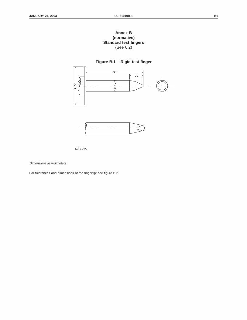
Annex B(normative)
Standard test fingers(See 6.2)
This is generated text for figtxt.
Figure B.1 – Rigid test finger
Dimensions in millimeters
For tolerances and dimensions of the fingertip: see figure B.2.
JANUARY 24, 2003 UL 61010B-1 B1

Figure B.2 – Jointed test finger
JANUARY 24, 2003UL 61010B-1B2

Annex C(normative)
Impact hammer(See 8.2)
IEC 68-2-63 describes the construction, the application and the calibration of the impact-test apparatus.The following brief description is not intended to give full details of how to make or calibrate the apparatus.
The test apparatus (see figure below) consists of three main parts: the body, the striking element and thespring-loaded release cone.
The body comprises the housing, the striking element guide, the release mechanism and all parts rigidlyfixed thereto.
The striking element comprises the hammer head, the hammer shaft and the cocking knob. The hammerhead has a hemispherical face of polyamide having a Rockwell hardness of HR 100, with a radius of 10mm; it is so fixed to the hammer shaft that the distance from its tip to the plane of the front of the conewhen the striking element is on the point of release is 20 mm.
The cone has a mass of 60 g and the cone spring is such that it exerts a force of 20 N when the releasejaws are on the point of releasing the striking element.
The apparatus is cocked by pulling the cocking knob until the release jaws engage in the hammer shaft.
For an impact energy of 0,5 J ± 0,05 J, the hammer spring is adjusted so that the product of thecompression, in millimeters, and the force exerted, in newtons, equals 1 000, the compression beingapproximately 20 mm.
For other energy levels, adjust as described in IEC 68-2-63 or according to the instructions supplied withthe apparatus.
This is generated text for figtxt.
JANUARY 24, 2003 UL 61010B-1 C1

JANUARY 24, 2003UL 61010B-1C2

Annex D(normative)
Tables for CLEARANCES and CREEPAGE DISTANCES in equipment and on printed wiring boards, and testvoltages
Contents
D.1 General
D.1.1 Working voltage
D.1.2 Notes on tables
D.2 Determination of CLEARANCE and CREEPAGE DISTANCE if the working voltage is up to 1 000 V and if INSTALLATION CATEGORIES (OVERVOLTAGE
CATEGORIES) are applicable
D.2.1 Applicable table
D.2.2 Application of tables D.1 to D.12
D.3 Determination of CLEARANCE for working voltage above 1 000 V r.m.s. or d.c.
D.3.1 CLEARANCE for BASIC INSULATION or SUPPLEMENTARY INSULATION
D.3.2 CLEARANCE for REINFORCED INSULATION
D.4 CLEARANCE in the primary of switching power supplies
D.5 Determination of CLEARANCE when neither clause D.2 nor table D.13 applies
D.5.1 General
D.5.2 Calculation of CLEARANCE for BASIC INSULATION or SUPPLEMENTARY INSULATION
D.5.3 CLEARANCE for REINFORCED INSULATION
D.6 Test voltages for insulations where the CLEARANCES are determined according to clause D.3 or D.5.
D.7 CLEARANCE, when homogeneous construction is employed
D.7.1 General
D.7.2 Testing of BASIC INSULATION or SUPPLEMENTARY INSULATION
D.7.3 Testing of REINFORCED INSULATION
D.7.4 Altitude correction of test voltages for testing homogeneous construction
D.8 Determination of CREEPAGE DISTANCES if clause D.2 does not apply
D.8.1 General
D.8.2 CREEPAGE DISTANCE for BASIC INSULATION or SUPPLEMENTARY INSULATION
D.8.3 CREEPAGE DISTANCE for REINFORCED INSULATION
D.9 CLEARANCE and CREEPAGE DISTANCE for equipment for use above an altitude of 2 000 m
D.10 Testing of circuits of components used to control overvoltage (see clause D.4 and D.5.1)
D.11 Rationale
D.11.1 Derivation of table D.13
D.11.2 Method for determination of CLEARANCE according to clause D.5
D.11.3 CLEARANCES for homogeneous construction (see clause D.7)
D.11.4 Altitude correction factors (see D.7.4)
D.1 General
This annex specifies CLEARANCES, CREEPAGE DISTANCES and overvoltages for dielectric strength tests, derivedfrom IEC 664.
CLEARANCE and CREEPAGE DISTANCES shall be measured according to IEC 664.
Circuits, other than mains circuits, that fail to comply with the requirements of this annex for CLEARANCE andCREEPAGE DISTANCE may be accepted, if compliance is achieved under the fault conditions described in 4.4,and if HAZARDOUS LIVE parts are not ACCESSIBLE after a fault.
JANUARY 24, 2003 UL 61010B-1 D1

D.1.1 Working voltage
The tables specify values in relation to working voltage, which is defined in IEC 664 as ″the highest r.m.s.value of the a.c. or d.c. voltage which may occur (locally) across any insulation at RATED supply voltage,transients being disregarded″, in open circuit conditions or in NORMAL USE. The tables for test voltages andCLEARANCES take into account the effect of transients (transient over-voltages) as determined for insulationcoordination in IEC 664.
D.1.2 Notes on tables
In IEC 664 insulating materials are separated into four groups by their Comparative Tracking Index (CTI)values as specified in IEC 112. For more information see IEC 664.
Material Group I 600 ≤ CTI
Material Group II 400 ≤ CTI< 600
Material Group IIIa 175 ≤ CTI < 400
Material Group IIIb 100 ≤ CTI< 175
Values of CREEPAGE DISTANCES for coated printed wiring boards apply to boards whose coatings meet therequirements for type A coatings given in IEC 664-3.
The peak impulse voltage test prescribed in tables D.1 to D.12 is the ″standard lightning impulse″ test asspecified in IEC 60-2. This is defined as a full lightning impulse having a virtual front time of 1,2 µs and avirtual time to half-value of 50 µs.
Information on the details of measurement, assessment of errors, etc. is given in IEC 60.
D.2 Determination of CLEARANCE and CREEPAGE DISTANCE if the working voltage is up to 1 000 V and ifINSTALLATION CATEGORIES (OVERVOLTAGE CATEGORIES) are applicable
D.2.1 Applicable table
The applicable table depends on:
– type of insulation. Tables D.1 to D.6 apply to BASIC INSULATION or SUPPLEMENTARY INSULATION, tablesD.7 to D.12 to DOUBLE INSULATION or REINFORCED INSULATION (see 6.4 to 6.6);
– INSTALLATION CATEGORIES (OVERVOLTAGE CATEGORIES) (see annex J);
– POLLUTION DEGREE (see 3.7.2 and 3.7.3). This is the POLLUTION DEGREE of the micro-environment ofthe CLEARANCE or CREEPAGE DISTANCE under consideration.
NOTES
1 It is the micro-environment of the CLEARANCE or CREEPAGE DISTANCE which determines the effect oninsulation, not the environment of the equipment as a whole. Micro-environment includes all factorsaffecting insulation, including climatic, electromagnetic, generation of POLLUTION, etc.
2 No CLEARANCES nor CREEPAGE DISTANCES can exist inside void-free moulded parts (see definitions 3.7.4and 3.7.5). The environment within sealed components is deemed to be POLLUTION DEGREE 1.
3 Values in tables D.1 to D.12 are valid up to an altitude of 2 000 m above sea level, CLEARANCE forhigher altitudes must be corrected to Paschen’s Law (see D.9).
JANUARY 24, 2003UL 61010B-1D2

4 The values given in annex D are minimum values. The manufacturer should make sure that thevalues will be maintained, taking account of production tolerances and other foreseeable influences.
5 Relative phasing between circuits or parts of circuits (e.g. transformers) may affect the actualworking voltage between them.
D.2.2 Application of tables D.1 to D.12
Interpolation of CREEPAGE DISTANCE is permissible. Interpolation of CLEARANCE is only permissible for a circuitor part which has no direct connection to the mains supply, but is powered from a transformer, converteror equivalent isolation device within the equipment (see also the notes to tables D.13, D.15 and D.16).For CLEARANCES in the primaries of switching power supplies, see clause D.4.
CREEPAGE DISTANCE shall always be at least as large as the value specified for CLEARANCE.
For CREEPAGE DISTANCE between two circuits, the actual working voltage which stresses the insulationbetween the circuits shall be used.
For test voltage and CLEARANCE between two circuits, the values for each circuit are obtained separatelyfrom the appropriate table, using the working voltage of each circuit. The higher values of test voltage andCLEARANCE shall then be used.
Table D.1 – BASIC INSULATION or SUPPLEMENTARY INSULATION
Workingvoltage (r.m.s.or d.c.) up to
POLLUTION DEGREE 1
INSTALLATION CATEGORY (OVERVOLTAGE CATEGORY) I
CLEARANCE CREEPAGE DISTANCE Test voltage
mm V
In equipment On printedwiring board
Peak impulse r.m.s. 50/60 Hz d.c. or 50/60 Hzpeak
V mm CTI > 100 CTI > 100 1,2/50µs 1 min 1 min
50 0,1 0,18 0,10 330 230 330
100 0,1 0,25 0,10 500 350 500
150 0,1 0,30 0,22 800 490 700
300 0,5 0,70 0,70 1 500 820 1 150
600 1,5 1,70 1,70 2 500 1 350 1 900
1 000 3,0 3,20 3,20 4 000 2 200 3 100
1 500 5,5 5,50 6 000 3 250 4 600
2 000 8,0 8,00 8 000 4 350 6 150
2 500 11,0 11,00 10 000 5 450 7 700
JANUARY 24, 2003 UL 61010B-1 D3

Table D.2 – BASIC INSULATION or SUPPLEMENTARY INSULATION
Working voltage(r.m.s. or d.c.) up
to
POLLUTION DEGREE 2
INSTALLATION CATEGORY (OVERVOLTAGE CATEGORY) I
CLEARANCE CREEPAGE DISTANCE Test voltage
mm V
In equipment On printed wiringboard
Peakimpulse
r.m.s.50/60 Hz
d.c. or50/60 Hz
peakMaterial group NotCoated
Coated
I II III
V mm CTI > 600 CTI > 400 CTI > 100 CTI > 175 CTI > 100 1,2/50 µs 1 min 1 min
50 0,2 0,6 0,85 1,2 0,20 0,10 330 230 330
100 0,2 0,7 1,00 1,4 0,20 0,10 500 350 500
150 0,2 0,8 1,10 1,6 0,35 0,22 800 490 700
300 0,5 1,5 2,10 3,0 1,40 0,70 1 500 820 1 150
600 1,5 3,0 4,30 6,0 3,00 1,70 2 500 1 350 1 900
1 000 3,0 5,0 7,00 10,0 5,00 3,20 4 000 2 200 3 100
1 500 5,5 7,5 10,50 15,0 6 000 3 250 4 600
2 000 8,0 10,0 14,00 20,0 8 000 4 350 6 150
2 500 11,0 12,5 18,00 25,0 10 000 5 450 7 700
Table D.3 – BASIC INSULATION or SUPPLEMENTARY INSULATION
Workingvoltage (r.m.s.or d.c.) up to
POLLUTION DEGREE 1
INSTALLATION CATEGORY (OVERVOLTAGE CATEGORY) II
CLEARANCE CREEPAGE DISTANCE Test voltage
mm V
In equipment On printedwiring board
Peak impulse r.m.s. 50/60 Hz d.c. or 50/60 Hzpeak
V mm CTI > 100 CTI > 100 1,2/50µs 1 min 1 min
50 0,1 0,18 0,1 500 350 500
100 0,1 0,25 0,1 800 490 700
150 0,5 0,50 0,5 1 500 820 1 150
300 1,5 1,50 1,5 2 500 1 350 1 900
600 3,0 3,00 3,0 4 000 2 200 3 100
1 000 5,5 5,50 5,5 6 000 3 250 4 600
1 500 8,0 8,00 8 000 4 350 6 150
2 000 11,0 11,00 10 000 5 450 7 700
2 500 14,0 14,00 12 000 6 500 9 200
JANUARY 24, 2003UL 61010B-1D4

Table D.4 – BASIC INSULATION or SUPPLEMENTARY INSULATION
Workingvoltage
(r.m.s. ord.c.) up to
POLLUTION DEGREE 2
INSTALLATION CATEGORY (OVERVOLTAGE CATEGORY) II
CLEARANCE CREEPAGE DISTANCE Test voltage
mm V
In equipment On printed wiringboard
Peakimpulse
r.m.s.50/60 Hz
d.c. or50/60 Hz
peakMaterial group NotCoated
Coated
I II III
V mm CTI > 600 CTI > 400 CTI > 100 CTI > 175 CTI > 100 1,2/50 µs 1 min 1 min
50 0,2 0,6 0,85 1,2 0,2 0,1 500 350 500
100 0,2 0,7 1,00 1,4 0,2 0,1 800 490 700
150 0,5 0,8 1,10 1,6 0,5 0,5 1 500 820 1 150
300 1,5 1,5 2,10 3,0 1,5 1,5 2 500 1 350 1 900
600 3,0 3,0 4,30 6,0 3,0 3,0 4 000 2 200 3 100
1 000 5,5 5,5 7,00 10,0 5,5 5,5 6 000 3 250 4 600
1 500 8,0 8,0 10,50 15,0 8 000 4 350 6 150
2 000 11,0 11,0 14,00 20,0 10 000 5 450 7 700
2 500 14,0 14,0 18,00 25,0 12 000 6 500 9 200
Table D.5 – BASIC INSULATION or SUPPLEMENTARY INSULATION
Workingvoltage (r.m.s.or d.c.) up to
POLLUTION DEGREE 1
INSTALLATION CATEGORY (OVERVOLTAGE CATEGORY) III
CLEARANCE CREEPAGE DISTANCE Test voltage
mm V
In equipment On printedwiring board
Peak impulse r.m.s. 50/60 Hz d.c. or 50/60 Hzpeak
V mm CTI > 100 CTI > 100 1,2/50 µs 1 min 1 min
50 0,1 0,18 0,1 800 490 700
100 0,5 0,50 0,50 1 500 820 1 150
150 1,5 1,50 1,5 2 500 1 350 1 900
300 3,0 3,00 3,0 4 000 2 200 3 100
600 5,5 5,50 5,5 6 000 3 250 4 600
1 000 8,0 8,00 8,0 8 000 4 350 6 150
JANUARY 24, 2003 UL 61010B-1 D5

Table D.6 – BASIC INSULATION or SUPPLEMENTARY INSULATION
Workingvoltage
(r.m.s. ord.c.) up to
POLLUTION DEGREE 2
INSTALLATION CATEGORY (OVERVOLTAGE CATEGORY) III
CLEARANCE CREEPAGE DISTANCE Test voltage
mm V
In equipment On printed wiringboard
Peakimpulse
r.m.s.50/60 Hz
d.c. or50/60 Hz
peakMaterial group Notcoated
Coated
I II III
V mm CTI > 600 CTI > 400 CTI > 100 CTI > 175 CTI > 100 1,2/50 µs 1 min 1 min
50 0,2 0,6 0,85 1,2 0,2 0,1 800 490 700
100 0,5 0,7 1,00 1,4 0,5 0,5 1 500 820 1 150
150 1,5 1,5 1,50 1,6 1,5 1,5 2 500 1 350 1 900
300 3,0 3,0 3,00 3,0 3,0 3,0 4 000 2 200 3 100
600 5,5 5,5 5,50 6,0 5,5 5,5 6 000 3 250 46 000
1 000 8,0 8,0 8,00 10,0 8,0 8,0 8 000 4 350 6 150
Table D.7 – DOUBLE INSULATION or REINFORCED INSULATION
Workingvoltage (r.m.s.or d.c.) up to
POLLUTION DEGREE 1
INSTALLATION CATEGORY (OVERVOLTAGE CATEGORY) I
CLEARANCE CREEPAGE DISTANCE Test voltage
mm V
In equipment On printedwiring board
Peak impulse r.m.s. 50/60 Hz d.c. or 50/60 Hzpeak
V mm CTI > 100 CTI > 100 1,2/50µs 1 min 1 min
50 0,10 0,35 0,10 560 400 560
100 0,12 0,50 0,20 850 510 720
150 0,40 0,60 0,45 1 360 740 1 050
300 1,60 1,60 1,60 2 550 1 400 1 950
600 3,30 3,40 3,40 4 250 2 300 3 250
1 000 6,50 6,50 6,50 6 800 3 700 5 250
1 500 11,50 11,50 10 200 5 550 7 850
2 000 16,00 16,00 13 600 7 400 10 450
2 500 21,00 22,00 17 000 9 300 13 150
JANUARY 24, 2003UL 61010B-1D6

Table D.8 – DOUBLE INSULATION or REINFORCED INSULATION
Workingvoltage
(r.m.s. ord.c.) up to
POLLUTION DEGREE 2
INSTALLATION CATEGORY (OVERVOLTAGE CATEGORY) I
CLEARANCE CREEPAGE DISTANCE Test voltage
mm V
In equipment On printed wiringboard
Peakimpulse
r.m.s.50/60 Hz
d.c. or50/60 Hz
peakMaterial group Notcoated
Coated
I II III
V mm CTI > 600 CTI > 400 CTI > 100 CTI > 175 CTI > 100 1,2/50 µs 1 min 1 min
50 0,2 1,2 1,7 2,4 0,4 0,10 560 400 560
100 0,2 1,4 2,0 2,8 0,4 0,20 850 510 720
150 0,4 1,6 2,2 3,2 0,7 0,45 1 360 740 1 050
300 1,6 3,0 4,2 6,0 2,8 1,60 2 550 1 400 1 950
600 3,3 6,0 8,5 12,0 6,0 3,40 4 250 2 300 3 250
1 000 6,5 10,0 14,0 20,0 10,0 6,50 6 800 3 700 5 250
1 500 11,5 15,0 21,0 30,0 10 200 5 550 7 850
2 000 16,0 20,0 28,0 40,0 13 600 7 400 10 450
2 500 21,0 25,0 36,0 50,0 17 000 9 300 13 150
Table D.9 – DOUBLE INSULATION or REINFORCED INSULATION
Workingvoltage (r.m.s.or d.c.) up to
POLLUTION DEGREE 1
INSTALLATION CATEGORY (OVERVOLTAGE CATEGORY) II
CLEARANCE CREEPAGE DISTANCE Test voltage
mm V
In equipment On printedwiring board
Peak impulse r.m.s. 50/60 Hz d.c. or 50/60 Hzpeak
V mm CTI > 100 CTI > 100 1,2/50 µs 1 min 1 min
50 0,12 0,35 0,12 850 510 720
100 0,40 0,50 0,40 1 360 740 1 050
150 1,60 1,60 1,60 2 550 1 400 1 950
300 3,30 3,30 3,30 4 250 2 300 3 250
600 6,50 6,50 6,50 6 800 3 700 5 250
1 000 11,50 11,50 11,50 10 200 5 550 7 850
1 500 16,00 16,00 13 600 7 400 10 450
2 000 21,00 22,00 17 000 9 300 13 150
2 500 26,00 28,00 20 400 11 100 15 700
JANUARY 24, 2003 UL 61010B-1 D7

Table D.10 – DOUBLE INSULATION or REINFORCED INSULATION
Workingvoltage
(r.m.s. ord.c.) up to
POLLUTION DEGREE 2
INSTALLATION CATEGORY (OVERVOLTAGE CATEGORY) II
CLEARANCE CREEPAGE DISTANCE Test voltage
mm V
In equipment On printed wiringboard
Peakimpulse
r.m.s.50/60 Hz
d.c. or50/60 Hz
peakMaterial group Notcoated
Coated
I II III
V mm CTI > 600 CTI > 400 CTI > 100 CTI > 175 CTI > 100 1,2/50 µs 1 min 1 min
50 0,2 1,2 1,7 2,4 0,4 0,12 850 510 720
100 0,4 1,4 2,0 2,8 0,4 0,40 1 360 740 1 050
150 1,6 1,6 2,2 3,2 1,6 1,60 2 550 1 400 1 950
300 3,3 3,3 4,2 6,0 3,3 3,30 4 250 2 300 3 250
600 6,5 6,5 8,5 12,0 6,5 6,50 6 800 3 700 5 250
1 000 11,5 11,5 14,0 20,0 11,5 11,50 10 200 5 550 7 850
1 500 16,0 16,0 21,0 30,0 13 600 7 400 10 450
2 000 21,0 22,0 28,0 40,0 17 000 9 300 13 150
2 500 26,0 28,0 36,0 50,0 20 400 11 100 15 700
Table D.11 – DOUBLE INSULATION or REINFORCED INSULATION
Workingvoltage (r.m.s.or d.c.) up to
POLLUTION DEGREE 1
INSTALLATION CATEGORY (OVERVOLTAGE CATEGORY) III
CLEARANCE CREEPAGE DISTANCE Test voltage
mm V
In equipment On printedwiring board
Peak impulse r.m.s. 50/60 Hz d.c. or 50/60 Hzpeak
V mm CTI > 100 CTI > 100 1,2/50 µs 1 min 1 min
50 0,4 0,4 0,4 1 360 740 1 050
100 1,6 1,6 1,6 2 550 1 400 1 950
150 3,3 3,3 3,3 4 250 2 300 3 250
300 6,5 6,5 6,5 6 800 3 700 5 250
600 11,5 11,5 11,5 10 200 5 550 7 850
1 000 16,0 16,0 16,0 13 600 7 400 10 450
JANUARY 24, 2003UL 61010B-1D8

Table D.12 – DOUBLE INSULATION or REINFORCED INSULATION
Workingvoltage
(r.m.s. ord.c.) up to
POLLUTION DEGREE 2
INSTALLATION CATEGORY (OVERVOLTAGE CATEGORY) III
CLEARANCE CREEPAGE DISTANCE Test voltage
mm V
In equipment On printed wiringboard
Peakimpulse
r.m.s.50/60 Hz
d.c. or50/60 Hz
peakMaterial group Notcoated
Coated
I II III
V mm CTI > 600 CTI > 400 CTI > 100 CTI > 175 CTI > 100 1,2/50 µs 1 min 1 min
50 0,4 1,2 1,7 2,4 0,4 0,4 1 360 740 1 050
100 1,6 1,6 2,0 2,8 1,6 1,6 2 550 1 400 1 950
150 3,3 3,3 3,3 3,3 3,3 3,3 4 250 2 300 3 250
300 6,5 6,5 6,5 6,5 6,5 6,5 6 800 3 700 5 250
600 11,5 11,5 11,5 12,0 11,5 11,5 10 200 5 550 7 850
1 000 16,0 16,0 16,0 20,0 16,0 16,0 13 600 7 400 10 450
D.3 Determination of CLEARANCE for working voltage above 1 000 V a.c. r.m.s. or d.c.
D.3.1 CLEARANCE for BASIC INSULATION or SUPPLEMENTARY INSULATION
a) For working voltages above 1 000 V a.c. r.m.s. or d.c., where neither overvoltage control norhomogeneous construction is employed within the equipment, the CLEARANCE of the table D.13applies.
CLEARANCE values in table D.13 are for high-voltage secondary circuits where the primary circuitsare low-voltage systems as described in IEC 664. The values for type 1 circuits apply when theprimary is INSTALLATION CATEGORY II (OVERVOLTAGE CATEGORY II) and the values for type 2 circuitsapply when the primary is INSTALLATION CATEGORY III (OVERVOLTAGE CATEGORY III).
NOTE – See also D.11.1 for rationale.
b) Acceptable CLEARANCES alternative to those of table D.13 may be calculated according toclause D.5, if applicable.
JANUARY 24, 2003 UL 61010B-1 D9

Table D.13 – CLEARANCE for BASIC INSULATION or SUPPLEMENTARY INSULATION for circuits with workingvoltage above 1 000 V a.c. r.m.s. or d.c.
Working voltage ( Uw) CLEARANCE
V mm
a.c. r.m.s. sinusoidal d.c., or peak if mixed or a.c.non-sinusoidal
Type 1 circuit Type 2 circuit
1 060 1 000 to 1 500 3,71 5,82
1 250 1 770 4,25 6,42
1 600 2 260 5,31 7,55
2 000 2 830 6,60 8,86
2 500 3 540 8,17 10,5
3 200 4 530 10,4 12,9
4 000 5 660 13,0 15,4
5 000 7 070 16,2 18,6
6 300 8 910 20,4 22,9
8 000 11 300 26,1 28,7
10 000 14 100 33,0 35,7
12 500 17 700 42,0 44,7
16 000 22 600 55,0 57,9
20 000 28 300 70,5 73,5
25 000 35 400 90,6 93,6
32 000 45 200 120 123
40 000 56 600 154 158
50 000 70 700 199 203
63 000 89 100 260 264
NOTE – Linear interpolation is permitted.
D.3.2 CLEARANCE for REINFORCED INSULATION
CLEARANCE for REINFORCED INSULATION shall be twice the CLEARANCE value determined for BASIC INSULATION orSUPPLEMENTARY INSULATION.
D.4 CLEARANCE in the primary of switching power supplies
The CLEARANCE between circuits connected to the mains and other circuits or ACCESSIBLE parts shall be notless than the CLEARANCE given in the appropriate table of D.1 to D.12. However, if a repetitive workingvoltage exists, whose peak value exceed the appropriate phase-to-earth voltage of table D.14 (caused forexample by voltage doubling). The CLEARANCE shall be calculated according to clause D.5.
CLEARANCE for circuits in which controlled overvoltage is employed (see D.5.1 and clause D.10) and whichare between poles of the mains, can be calculated according to clause D.5.
D.5 Determination of CLEARANCE when neither clause D.2 nor table D.13 applies
D.5.1 General
Clause D.5 enables CLEARANCES to be calculated if the maximum voltage Ûm (peak value of working voltageplus transient overvoltage) meets one of the following criteria:
JANUARY 24, 2003UL 61010B-1D10

a) It is controlled within the equipment to levels below the impulse withstand voltages of tableD.14; In circuits other than mains circuits, lower values than those of clause D.2 can be used.For a mains circuit, lower values are only permitted within parts of the circuit where controlledovervoltage is employed.
b) It is above the impulse withstand voltages of table D.14;
c) It includes a working voltage as described in clause D.4;
d) It includes a working voltage which is the sum of voltages from more than one circuit or amixed voltage.
NOTE – The term ″controlled overvoltage ″ refers to the condition in which means have been taken within
the equipment to limit the peak level of transient overvoltage (see also clause D.10).
The transient overvoltage which is caused by phenomenon such as lightning or load switching, adds to
the peak value of working voltage raising the level to the maximum voltage.
Table D.14 – Impulse withstand voltage (derived from table J.1 of annex J)
Voltage phase-to-earth
Preferred series of impulse withstand voltages for
INSTALLATION CATEGORY I to III
(OVERVOLTAGE CATEGORY I to III)
V
V r.m.s. I II III
50 330 500 800
100 500 800 1 500
150 800 1 500 2 500
300 1 500 2 500 4 000
600 2 500 4 000 6 000
1000 4 000 6 000 8 000
D.5.2 Calculation of CLEARANCE for inhomogeneous construction, for BASIC INSULATION or SUPPLEMENTARY
INSULATION
For calculation of CLEARANCE table D.15 applies (see also D.11.2). Two values of CLEARANCE are given intable D.15. CLEARANCE D1 is the CLEARANCE for a 1,2 x 50 µs impulse of the maximum voltage Ûm.
CLEARANCE D2 is for a working voltage (d.c., a.c. or mixed) without transient overvoltages. In this case, Ûmand the peak value of the working voltage are the same.
The calculation is made in the following order:
JANUARY 24, 2003 UL 61010B-1 D11

a) Determine peak value of the working voltage at the highest level, according to the reference test conditions of 4.3 Ûw = ____V peak
b) Determine maximum voltage Ûm = ____V peak
NOTE – The term ″maximum voltage″ (Ûm ) is the peaklevel resulting from the addition of a transient overvoltage(Ûi) to the peak value of the working voltage (Ûw): Ûm = Ûw+ Ûi
c) Determine CLEARANCES D1 and D2 from table D.15, both relating to maximum voltage D1 = ____mm
D2 = ____mm
d) Interpolation between CLEARANCES D1 and D2 is based on the ratio of peak value of working voltage divided by maximumvoltage
Calculate ratio Ûw /Ûm Ratio = ____
The interpolation factor F is taken from figure D.1 F = ____
Calculate: CLEARANCE = D1 + F (D2 - D1) = ____
After the calculation of CLEARANCE, correction for altitude above 2 000 m (see clause D.9) is considered ifappropriate. If the final CLEARANCE is below the minimum, the CLEARANCE is raised to the minimum (minimumCLEARANCE is 0,01 mm for POLLUTION DEGREE 1 and 0,2 mm for POLLUTION DEGREE 2) (see table II of IEC 664).
This is generated text for figtxt.
JANUARY 24, 2003UL 61010B-1D12

Figure D.1 – Interpolation factor (F) for CLEARANCE
JANUARY 24, 2003 UL 61010B-1 D13

Table D.15 – Range of CLEARANCE related to maximum voltage for BASIC INSULATION or SUPPLEMENTARY
INSULATION
CLEARANCE
mm
When Ûm is mainly impulse When Û m is working voltage with noimpulse
Ûm in V D1 (see note 2) D2 (see note 2)
14,1 to 266 0,010 0,010
283 0,010 0,013
330 0,010 0,020
354 0,013 0,025
453 0,027 0,052
500 0,036 0,071
566 0,052 0,10
707 0,081 0,20
800 0,099 0,29
891 0,12 0,41
1 130 0,19 0,83
1 410 0,38 1,27
1 500 0,45 1,40
1 770 0,75 1,79
2 260 1,25 2,58
2 500 1,45 3,00
2 830 1,74 3,61
3 540 2,44 5,04
4 000 2,93 6,05
4 530 3,53 7,29
5 660 4,92 10,1
6 000 5,37 10,8
7 070 6,86 13,1
8 000 8,25 15,2
8 910 9,69 17,2
11 300 12,9 22,8
14 100 16,7 29,5
17 700 21,8 38,5
22 600 29,0 51,2
28 300 37,8 66,7
35 400 49,1 86,7
45 300 65,5 116
56 600 85,0 150
70 700 110 195
89 100 145 255
NOTES
1 Linear interpolation is permitted.
2 CLEARANCE values are to two significant figures for CLEARANCE below 1 mm and three significant figures for CLEARANCES ≥ 1 mm.
JANUARY 24, 2003UL 61010B-1D14

D.5.3 CLEARANCE for REINFORCED INSULATION
CLEARANCE for REINFORCED INSULATION shall be twice the CLEARANCE values determined for BASIC INSULATION orSUPPLEMENTARY INSULATION.
D.6 Test voltages for insulations where the CLEARANCES are determined according to clause D.3 orD.5.
Test voltages are based on CLEARANCE and are given in table D.16 (minimum CLEARANCE is 0,01 mm forPOLLUTION DEGREE 1 and 0,2 mm for POLLUTION DEGREE 2).
Table D.16 – Test voltage related to CLEARANCE
Test voltage Test voltage
V V
CLEARANCE r.m.s. d.c. or a.c. Peak impulse CLEARANCE r.m.s. d.c. or a.c. Peak impulse
mm 50 Hz - 60 Hz peak 1,2x50 µs mm 50 Hz - 60 Hz peak 1,2x50 µs
0,010 231 327 327 8,3 4 370 6 180 8 040
0,015 265 374 374 10 4 950 7 000 9 100
0,022 300 425 425 12 5 790 8 180 10 600
0,032 340 481 481 15 7 000 9 900 12 900
0,046 383 542 542 18 8 180 11 600 15 000
0,0625 424 600 600 22 9 710 13 700 17 800
0,068 436 617 633 26 11 200 15 800 20 600
0,10 495 700 806 32 13 400 18 900 24 600
0,15 566 801 1 040 38 15 500 21 900 28 500
0,22 643 909 1 180 46 18 200 25 800 33 500
0,32 727 1 030 1 340 56 21 600 30 500 39 600
0,46 820 1 160 1 510 68 25 400 36 000 46 800
0,68 933 1 320 1 720 83 15 500 42 700 55 500
1,0 1 060 1 500 1 950 100 35 400 50 000 65 000
1,2 1 200 1 700 2 200 120 41 300 58 500 76 000
1,5 1 390 1 970 2 560 150 50 000 70 700 92 000
1,8 1 570 2 220 2 890 180 58 400 82 600 107 000
2,2 1 800 2 540 3 310 220 69 400 98 100 128 000
2,6 2 010 2 840 3 700 260 80 000 113 000 147 000
3,2 2 310 3 270 4 250 264 81 100 115 000 149 000
3,8 2 590 3 670 4 770
4,6 2 950 4 170 5 410
5,6 3 360 4 750 6 180
6,8 3 830 5 410 7 030
NOTES
1 Linear interpolation is permitted.
2 See D.11.3 for rationale.
JANUARY 24, 2003 UL 61010B-1 D15

D.7 CLEARANCE, when homogeneous construction is employed
D.7.1 General
In circuits other than mains circuits, reduced CLEARANCES can be accepted if the construction ishomogeneous or nearly homogeneous and if they pass the appropriate test specified in D.7.2 or D.7.3(see also D.11.4 for rationale). For mains circuits, lower values are permitted only for those parts of a highvoltage circuit exceeding 1 000 V.
NOTE – The term ″homogeneous construction ″ refers to construction in which the shape and arrangement of
conductive parts, between which a CLEARANCE exists, are such that homogeneous or near homogeneous electric
field conditions exist in the CLEARANCE.
The test voltages specified in D.7.2 and D.7.3 are based on an altitude of 2 000 m. If the test site is atanother altitude the voltage shall be corrected according to table D.17 when verifying CLEARANCE withhomogeneous construction.
D.7.2 Testing of BASIC INSULATION or SUPPLEMENTARY INSULATION
The test voltage is d.c., or a.c. 50 Hz/60 Hz.
For CLEARANCES below the value of the appropriate table of D.1 to D.6 the test voltage shall have the samepeak value as the appropriate impulse withstand voltage from table D.14.
For CLEARANCES below the values of table D.13 or below the calculated values of D.5.1 or D.5.2, the testvoltage is based on the CLEARANCE value specified in table D.13 or on the calculated value according toD.5.2. The test voltage shall have the same peak value as the impulse test voltage given in table D.16.
NOTE – Minimum CLEARANCE is 0,01 mm for POLLUTION DEGREE 1 and 0,2 mm for POLLUTION DEGREE 2.
D.7.3 Testing of REINFORCED INSULATION
For CLEARANCES below the value of the appropriate table of clauses D.7 to D.12 the test voltage shall havethe same peak value as the appropriate impulse withstand voltage from table D.14 multiplied by the factor1,6.
For CLEARANCES below the calculated values of D.3.2 and D.5.3, the test voltage is based on the calculatedCLEARANCE. The test voltage shall have the same peak value as the impulse test voltage given in table D.16.
NOTE – Minimum CLEARANCE is 0,01 mm for POLLUTION DEGREE 1 and 0,2 mm for POLLUTION DEGREE 2.
JANUARY 24, 2003UL 61010B-1D16

D.7.4 Altitude correction of test voltages for testing homogeneous construction
Factors for correction of test voltage, when the test site is at an altitude different from 2 000 m, are givenin table D.17. The factors are to be used only when using a voltage test to qualify a CLEARANCE ofhomogeneous construction. When applicable, the test voltage for 2 000 m is to be multiplied by theappropriate factor. The new test voltage will provide the same voltage stress relative to breakdown of aCLEARANCE at the test site altitude as would the original test voltage at 2 000 m.
Table D.17 – Correction factors for test voltage according to test site altitude
Test site altitude Altitude correction factors for ranges of test voltage
327 Vpeak < Ûtest 600 Vpeak < Ûtest 3 500 Vpeak < Ûtest 25 kVpeak < Ûtest
< 600 Vpeak < 3 500 Vpeak < 25 kVpeak
231 Vr.m.s. < Utest 424 Vr.m.s. < Utest 2 475 Vr.m.s. < Utest 17,7 kVr.m.s. < Utest
m < 424 Vr.m.s. < 2 475 Vr.m.s. < 17,7 kVr.m.s.
Sea level 1,08 1,16 1,22 1,24
500 1,06 1,12 1,16 1,17
1 000 1,04 1,08 1,11 1,12
2 000 1,00 1,00 1,00 1,00
3 000 0,96 0,92 0,89 0,88
4 000 0,92 0,85 0,80 0,79
5 000 0,88 0,78 0,71 0,70
D.8 Determination of CREEPAGE DISTANCES if clause D.2 does not apply
D.8.1 General
CREEPAGE DISTANCES are determined according to D.8.2 or D.8.3, if clause D.2 does not apply or whenalternatives to tables D.1 to D.12 are needed in those cases where the CLEARANCES are determinedaccording to clauses D.3, D.4, D.5 and D.7.
D.8.2 CREEPAGE DISTANCE for BASIC INSULATION or SUPPLEMENTARY INSULATION
CREEPAGE DISTANCE is obtained from table D.18 for the working voltage.
If this CREEPAGE DISTANCE is below the calculated CLEARANCE, the CREEPAGE DISTANCE shall be equal to thecalculated value of CLEARANCE.
JANUARY 24, 2003 UL 61010B-1 D17

D.8.3 CREEPAGE DISTANCE for REINFORCED INSULATION
The CREEPAGE DISTANCE for REINFORCED INSULATION shall be twice the value of that for BASIC INSULATION.
Table D.18 – CREEPAGE DISTANCE
Workingvoltage r.m.s.or d.c. up to
CREEPAGE DISTANCE
mm
POLLUTION DEGREE POLLUTION DEGREE
1 2 1 2
On printed wiring board Other material Material group
I II IIIa/IIIb
V CTI > 600 CTI > 400 CTI > 100
10 0,025 0,040 0,080 0,40 0,40 0,40
12,5 0,025 0,040 0,090 0,42 0,42 0,42
16 0,025 0,040 0,10 0,45 0,45 0,45
20 0,025 0,040 0,11 0,48 0,48 0,48
25 0,025 0,040 0,125 0,50 0,50 0,50
32 0,025 0,040 0,14 0,53 0,53 0,53
40 0,025 0,040 0,16 0,56 0,80 1,1
50 0,025 0,040 0,18 0,60 0,85 1,2
63 0,040 0,063 0,20 0,63 0,90 1,25
80 0,063 0,10 0,22 0,67 0,95 1,3
100 0,10 0,16 0,25 0,71 1,0 1,4
125 0,16 0,25 0,28 0,75 1,05 1,5
160 0,25 0,40 0,32 0,80 1,1 1,6
200 0,40 0,63 0,42 1,0 1,4 2,0
250 0,56 1,0 0,56 1,25 1,8 2,5
320 0,75 1,6 0,75 1,6 2,2 3,2
400 1,0 2,0 1,0 2,0 2,8 4,0
500 1,3 2,5 1,3 2,5 3,6 5,0
630 1,8 3,2 1,8 3,2 4,5 6,3
800 2,4 4,0 2,4 4,0 5,6 8,0
1 000 3,2 5,0 3,2 5,0 7,1 10
1 250 4,2 6,3 9,0 12,5
1 600 5,6 8,0 11 16
2 000 7,5 10 14 20
2 500 10 12,5 18 25
3 200 12,5 16 22 32
4 000 16 20 28 40
5 000 20 25 36 50
6 300 25 32 45 63
8 000 32 40 56 80
10 000 40 50 71 100
12 500 50 63 90 125
16 000 63 80 110 160
20 000 80 100 140 200
25 000 100 125 180 250
32 000 125 160 220 320
JANUARY 24, 2003UL 61010B-1D18
Table D.18 – CREEPAGE DISTANCE Continued on Next Page

Table D.18 – CREEPAGE DISTANCE Continued
Workingvoltage r.m.s.or d.c. up to
CREEPAGE DISTANCE
mm
POLLUTION DEGREE POLLUTION DEGREE
1 2 1 2
On printed wiring board Other material Material group
I II IIIa/IIIb
V CTI > 600 CTI > 400 CTI > 100
40 000 160 200 280 400
50 000 200 250 360 500
63 000 250 320 450 630
D.9 CLEARANCE and CREEPAGE DISTANCE for equipment for use above an altitude of 2 000 m
CLEARANCE and CREEPAGE DISTANCE and test voltages given in annex D are calculated for an altitude of 2 000m.
Table D.19, derived from IEC 664, gives factors for CLEARANCE for altitudes above 2 000 m. The factors arenot applied to CREEPAGE DISTANCE. CREEPAGE DISTANCE shall always be at least as large as the value specifiedfor CLEARANCE.
Table D.19 – Multiplication factors for CLEARANCE for altitudes up to 5 000 m
Altitude Multiplication factor
m
2 000 1,00
3 000 1,14
4 000 1,29
5 000 1,48
D.10 Testing of circuits or components used to control overvoltage (see clause D.4 and D.5.1)
Where controlled overvoltage is employed in the equipment, any overvoltage limiting component or circuitshall withstand 10 positive and 10 negative impulses with the appropriate voltage of table D.14, spacedup to 1 min apart, from a 1,2 x 50 µs impulse generator. The maximum generator impedance shall be thatgiven for the INSTALLATION CATEGORY (OVERVOLTAGE CATEGORY) of the circuit in which the limiting component isapplied.
The generator shall produce an open circuit voltage waveform of 1,2 x 50 µs and a short circuit currentwaveform of 8 x 20 µs. The output impedance is defined as the peak open circuit voltage divided by thepeak short-circuit current and values are given in table D.20.
JANUARY 24, 2003 UL 61010B-1 D19

Table D.20 – Output impedance for impulse generators
INSTALLATION CATEGORY Output impedance
(OVERVOLTAGE CATEGORY) ΩIII 2
II 12 (see note)
I 30 (see note)
NOTE – Resistance can be added in series with a lower impedance generator to raise the impedance to the appropriate value.
Compliance is checked by the above test. After the test there shall be no sign of overload, nor degradationof performance of a component.
D.11 Rationale
D.11.1 Derivation of table D.13
CLEARANCE values for table D.13 were calculated by the method of clause D.5. The peak value of theworking voltage for the calculation was the peak voltage shown in table D.13. The maximum level ofimpulse overvoltage was the sum of the peak value of the working voltage and the maximum expectedimpulses of 2 600 V for type 1 or 4 600 V for type 2 high-voltage circuits.
These maximum expected levels were derived, according to the intent if IEC 664 by first reducing thewithstand voltages by one INSTALLATION CATEGORY (OVERVOLTAGE CATEGORY) to account for the impulse loss inthe primary-to-secondary transfer. The 1 000 V phase-to-earth condition (see table D.14) was chosen toinclude the worst case impulse level that is expected. This leads to withstand voltages of 4 000 V ifderived from a primary circuit of INSTALLATION CATEGORY (OVERVOLTAGE CATEGORY) II or 6 000 V if derived fromINSTALLATION CATEGORY (OVERVOLTAGE CATEGORY) III. Secondly, the rounded peak phase-to-earth voltage of 1400 V was subtracted from the 4 000 V or 6 000 V withstand voltage to extract the maximum expectedimpulse level of 2 600 V or 4 600 V.
D.11.2 Method for determination of CLEARANCE according to clause D.5
The method for determination of CLEARANCE involves calculation based on the peak working voltage (Ûw)and the maximum voltage (Ûm) which is the sum of peak working voltage and impulse overvoltage. Themethod is illustrated in figure D.2 which is figure A1 of IEC 664. The figure shows three possibilities forCLEARANCE at a specified value of Ûm. The CLEARANCE for 2 500 V peak are illustrated:
– line (1) shows that a CLEARANCE of 0,6 mm is the minimum to withstand 2 500 V peak whenhomogeneous construction is employed (point k);
– line (2) shows that a CLEARANCE of 1,5 mm will withstand 2 500 V peak if the voltage is a pureimpulse and the construction is inhomogeneous. This relates to impulse overvoltage (point l);
– line (3) indicates that a CLEARANCE of 2,15 mm is required to withstand 2 500 V peak if thevoltage is 50 Hz/60 Hz and the construction is inhomogeneous. This relates to working voltagewithout impulse overvoltage (point m).
In practice, the CLEARANCE, for inhomogeneous construction, which is normal, will be a minimum of line (2)up to line (3) depending on the ratio of Ûw/Ûm. The method for CLEARANCE in controlled overvoltageconditions provided in table D.15 gives the two CLEARANCES and a method of interpolation based on the ratioof Ûw/Ûm (see figure D.1).
JANUARY 24, 2003UL 61010B-1D20

When determining the CLEARANCE values when Ûm is working voltage with no impulse (column D2 of tableD.15), a margin has been provided to ensure that the test voltage and the breakdown voltage will alwaysbe above the working voltage. The CLEARANCE values in column D2 of table D.15 are those for voltagevalues which are multiplied by a factor of 1,25, using line (3) of figure D.2. For example, the CLEARANCE
value for 2 500 V peak shown in table D.15 is 3,0 mm which is the CLEARANCE for 1,25 x 2 500 V = 3 125V peak on line (3) (point n).This is generated text for figtxt.
JANUARY 24, 2003 UL 61010B-1 D21

Figure D.2 – Withstand voltage for an altitude of 2 000 m above sea level
JANUARY 24, 2003UL 61010B-1D22

Example for calculation of CLEARANCE (see D.5.2):
a) Determine peak value of the working voltage at the highest level, according to the reference testconditions of 4.3
Ûw = 5 000 Vpeak
b) Determine maximum voltage Ûm = 7 500 Vpeak
c) Determine CLEARANCES D1 and D2 from table D.15, both relating to maximum voltage D1 = 7,55 mm
D2 = 14,07 mm
d) Interpolation between CLEARANCE D1 and D2 is based on the ratio of peak value of working voltagedivided by maximum voltage
Calculate ratio Ûw/Ûm Ratio = 0,666
The interpolation factor F is taken from figure D.1 F = 0,58
Calculate: CLEARANCE = D1 + F(D2 - D1) = 7,55 + 0,58 x 6,52
= 11,3 mm
D.11.3 CLEARANCE for homogeneous construction (see clause D.7)
A method is also provided for CLEARANCES when the construction is homogeneous. While all tables forCLEARANCES in this standard are valid for inhomogeneous construction and need no verification by a voltagetest, the validity of CLEARANCES with homogeneous construction requires testing for voltage withstand andif the altitude is other than 2 000 m, adjustment of the test voltage for the test site altitude.
For further information on this context see IEC 664.
D.11.4 Altitude correction factors (see D.7.4)
Table D.17 provides test voltage correction factors for test site altitudes different from 2 000 m. Thesefactors were calculated from equations which define the withstand voltage under homogeneous fieldconditions shown in curve (1) of figure D.2. The equations are given in four segments as follows:
Û1 = 1 500 D 0,3305 0,01 mm < D < 0,0625 mm
327 V < Û < 600 V
Û2 = 3 500 D 0,6361 0,0625 mm < D < 1 mm
600 V < Û < 3 500 V
Û3 = 3 500 D 0,8539 1 mm < D < 10 mm
3 500 V < Û < 25 kV
Û4 = 2 976 D 0,9243 10 mm < D
25 kV < Û < 210 kV
A test voltage is corrected to test site attitude by a factor which is the ratio of withstand voltage at the testsite pressure to the withstand voltage at a pressure for 2 000 m. For example, a sea level correction factorfor voltages between 600 V and 3 500 V is calculated using equation Û2 as follows
JANUARY 24, 2003 UL 61010B-1 D23

See appendix A of IEC 664:
Pressure at sea level = 101,3 kPa
Pressure at 2 000 m = 80 kPa
JANUARY 24, 2003UL 61010B-1D24

Annex E(normative)
Guidance on parts between which insulation requirements are specified
The following symbols are used for the figures indicate:
B A test for BASIC INSULATION is required.
D A test for DOUBLE INSULATION or REINFORCED INSULATION is required.
The secondary circuits shown may also be regarded merely as a part.
In the diagrams of this annex, HAZARDOUS LIVE means HAZARDOUS LIVE in NORMAL CONDITION.
E.1 Protection between HAZARDOUS LIVE circuits and circuits not exceeding the values of 6.3.2 inNORMAL CONDITION and having external TERMINALS of ACCESSIBLE parts (see figure E.1.1 to E.1.8)
This is generated text for figtxt.
Figure E.1.1
JANUARY 24, 2003 UL 61010B-1 E1

Figure E.1.2
Figure E.1.3
JANUARY 24, 2003UL 61010B-1E2

Figures E.1.4 and E.1.5
Figure E.1.6
JANUARY 24, 2003 UL 61010B-1 E3

Figure E.1.7
Figure E.1.8
*May be B, if Z is sufficiently low (see 6.6.1).
JANUARY 24, 2003UL 61010B-1E4

E.2 Protection between HAZARDOUS LIVE internal circuits and circuits not exceeding the values of6.3.2 in NORMAL CONDITIONS and having external TERMINALS or ACCESSIBLE parts (see figures E.2.1 toE.2.4)
NOTE – Other means of protection are also possible for circuits E.2.3 and E.2.4, such as protective screening,
PROTECTIVE BONDING or circuits (see 6.6.1) and PROTECTIVE IMPEDANCE.
This is generated text for figtxt.
Figure E.2.1
JANUARY 24, 2003 UL 61010B-1 E5

Figure E.2.2
Figure E.2.3
JANUARY 24, 2003UL 61010B-1E6

E.3 Protection between two or more HAZARDOUS LIVE circuits, having external TERMINALS or ACCESSIBLE
parts (see figure E.3.1)
This is generated text for figtxt.
Figure E.2.4
JANUARY 24, 2003 UL 61010B-1 E7

The insulation between each circuit and the exterior or ACCESSIBLE parts shall be in accordance with therequirements for HAZARDOUS LIVE of E.1 and E.2.
The test requirements for X shall be determined from the most severe of the following applicableconditions:
B(basic) – where HAZARDOUS LIVE 1 and HAZARDOUS LIVE 2 are both connected and based on the highest RATED
working voltage that stresses the insulation between the circuits in accordance with Annex D;
D(double) – where HAZARDOUS LIVE 1 is connected and the TERMINALS for HAZARDOUS LIVE 2 are ACCESSIBLE forconnection purposes, based on the highest RATED working voltage that stresses the insulation forHAZARDOUS LIVE 1 in accordance with annex D;
D(double) – where HAZARDOUS LIVE 2 is connected and the TERMINALS for HAZARDOUS LIVE 1 are ACCESSIBLE forconnection purposes, based on the highest RATED working voltage that stresses the insulation forHAZARDOUS LIVE 2 in accordance with annex D.
Figure E.3.1
JANUARY 24, 2003UL 61010B-1E8

Annex F(normative)
Protection against the spread of fire
F.1 General
This annex provides an alternative means of satisfying the requirements of 9.1 for protection against thespread of fire.
This annex explains methods and procedures to reduce to a safe level by one of the following means therisk of fire associated with equipment:
– eliminating or reducing the sources of ignition within the equipment;
– reducing the fuels provided;
– containment of a fire within the equipment, should it occur.
Rationale
Equipment or parts of equipment might cause, due to normal or abnormal operation, excessivetemperatures which could lead to a risk of fire within the equipment or to the surroundings.
In order for a risk of fire within the equipment to exist, all three of the basic elements below must exist:
– the equipment circuits must have sufficient power or energy to be an ignition source;
– there must be oxygen present (ambient air is about 21% oxygen);
– there must be a fuel present to support the combustion process.
The use of the methods and procedures of this annex offers the following benefits:
– compliance with fire protection requirements without tests;
– reduction of fault condition testing according to 4.4;
– specification of construction methods which allow verification of fire protection by inspection;
– reduction of interpretation differences and testing variables between inspection authorities.
F.2 Circuit classifications
F.2.1 Limited circuit
A limited circuit is a circuit supplied by sources such as a battery or a transformer winding where theopen-circuit potential is not more than 30 V r.m.s or 42,4 V d.c., and the energy available to the circuit islimited according to one of the following means:
– the current under any condition of load, including short circuit, is not more than 8 A measuredafter 1 min of operation;
JANUARY 24, 2003 UL 61010B-1 F1

– the source is RATED or set to limit its power output to 150 VA under any condition of loadincluding short circuit;
– an overload protector or circuit component opens to interrupt the power output at a lowervalue then 150 VA under any condition of load including short circuit.
There are no requirements for protection against the spread of fire from limited circuits.
F.2.2 Unlimited circuit
An unlimited circuit is a circuit other than a limited circuit (see F.2.1).
NOTE – Examples of unlimited circuits include:
– mains circuits;
– some measuring circuits;
– some circuits supplied by a transformer winding or battery.
F.3 Considerations for risk of fire, fire ignition sources
All circuits of equipment which can be classified as including an unlimited circuit (see F.2.2) shall beconsidered to be an ignition source of fire.
All electrical components of unlimited circuits are considered likely to be an ignition source of fire.
F.4 Requirements for unlimited circuits
F.4.1 General
The risk of fire in unlimited circuits shall be considered to have been reduced to a safe level if at least oneof the following conditions is present:
– energizing of the equipment is controlled by a switch that is held closed by the OPERATOR, andunlimited circuits of the equipment and the equipment ENCLOSURE, comply with the constructionalrequirements of F.4.2.1 to F.4.2.3;
– the unlimited circuits of the equipment and the equipment ENCLOSURE comply with theconstructional requirements of F.4.2 and use only motors, transformers, etc., with provisions forovercurrent protection or overtemperature protection, and which comply with the relevant IECstandard or with 14.2 (motors) and 14.7 (transformers).
Compliance is checked by inspection. If these requirements are not fulfilled, the tests of 4.4.4.3 shall beperformed, together with any other relevant fault condition tests of 4.4.
JANUARY 24, 2003UL 61010B-1F2

F.4.2 Constructional requirements
F.4.2.1 Connectors, wiring and other current-carrying parts of unlimited circuits shall be types meeting therelevant IEC standard.
Compliance is checked by inspection.
F.4.2.2 Printed boards of unlimited circuits shall be RATED to have a flammability classification of FV 0, FV1, or FV 2 in accordance with IEC 707.
Compliance is checked by inspection.
F.4.2.2DV D2 Addition:
UL 94 flame RATINGS V-0, V-1, and V-2 are equivalent to the designations of IEC 707 FV0, FV1,and FV2 respectively.
F.4.2.3 The equipment ENCLOSURE containing unlimited circuits, or part of an equipment ENCLOSURE
surrounding unlimited circuits, shall comply with the requirements of 6.2 and F.4.3.
Compliance is checked by inspection.
F.4.2.4 The insulation of wire used for unlimited circuits shall have flame retardant properties inaccordance with the relevant IEC standard.
Compliance is checked by inspection.
F.4.3 ENCLOSURES
In addition to the rigidity requirements for flame BARRIERS and ENCLOSURES of 6.4 for basic protection againstelectric shock, the flame BARRIERS and ENCLOSURES shall meet the requirements of F.4.3.1 to F.4.3.3.
F.4.3.1 High-current devices such as fuse holders and circuit breakers designed for use only with asupplementary ENCLOSURE shall be covered by a door or cover, which is hinged or otherwise permanentlyattached and meets the following requirements:
– means shall be provided to hold the door in a closed position;
– the door or cover shall fit in such a manner that the gap between the door or cover and theENCLOSURE shall not exceed 1,6 mm.
Compliance is checked by inspection.
F.4.3.2 The bottom of an ENCLOSURE containing unlimited circuits, or the part of an ENCLOSURE surroundingunlimited circuits, shall have no openings or shall be constructed in accordance with one of the following:
– figure F.1 and table F.1;
– figure F.2 for components of unlimited circuits.
Compliance is checked by inspection.
JANUARY 24, 2003 UL 61010B-1 F3

F.4.3.3 The ENCLOSURE, baffle, or flame BARRIER shall be made of metal (except magnesium) or ofnon-metallic materials having a flammability classification of FV 0, FV 1, or FV 2 in accordance with IEC707.
Compliance is checked by inspection of data on the materials used for ENCLOSURES, baffles or flameBARRIERS. Alternatively, compliance is checked by performing the FV test of IEC 707 on three samples ofthe relevant parts. The samples may be any of the following:
– complete parts;
– sections of the part, including the area with the least wall thickness and any vent openings;
– specimens in accordance with IEC 707.
F.4.3.3DV D2 Addition:
UL 94 flame RATINGS of UL V-0, V-1, and V-2 are equivalent to the designations of IEC 707FV0, FV1, and FV2 respectively.
This is generated text for figtxt.
Figure F.1 – Baffle (see F.4.3.2 and F.4.3.3)
JANUARY 24, 2003UL 61010B-1F4

Table F.1 – Acceptable perforated metal plates
Minimum thickness Maximum diameter of holes Minimum spacing of holes, centre tocentre
mm mm mm
0,76 1,1 1,7 (35 holes/100 mm2)
0,76 1,2 2,4
0,89 1,9 3,2 (10 holes/100 mm2)
0,99 1,6 2,7This is generated text for figtxt.
JANUARY 24, 2003 UL 61010B-1 F5

Figure F.2 – Location and extent of a non-combustible flame BARRIER
(see F.4.3.2 and F.4.3.3)
A – Region to be shielded by the flame BARRIER. This consists of the entire component if it is not otherwise shielded, orthe unshielded portion of a component that is partially shielded by its casing.
B – Projection of the outline of the component on the horizontal plane.
C Inclined line that traces out the minimum area of the flame BARRIER. This line projects at a 5° angle from the verticalat every point around the perimeter of the component and is oriented so as to trace out the maximum area.
D – Minimum area for the flame BARRIER.
JANUARY 24, 2003UL 61010B-1F6

Annex G(normative)
Circuits between which the adequacy of insulation shall be tested for protection against fire(see 9.1)
Tests shall be made between the following circuits:
Table G.1
1–2 2–2 3–3 4–4 5–5
1–3 2–3 3–4 4–5 5–6
1–4 2–4 3–5 4–6
1–5 2–5 3–6
1–6 2–6
1) Mains circuits (including measuring and control circuits connected to the mains supply).
2) Circuits with external TERMINALS which carry or are intended for connection to HAZARDOUS LIVE voltage or current exceeding thevalues of 6.3.2 in NORMAL CONDITION (other than mains, e.g. measuring or control circuits).
3) Circuits connected to ACCESSIBLE parts, but without external TERMINALS, which carry HAZARDOUS LIVE voltage or current exceedingthe values of 6.3.2 in NORMAL CONDITION (internal circuits).
4) Circuits without external TERMINALS which carry voltage or current not exceeding the values of 6.3.2 in NORMAL CONDITION (internalcircuits).
5) Circuits with external TERMINALS which carry or are intended for connection to voltage or current not exceeding the values of6.3.2 in NORMAL CONDITION (for example TERMINALS of measuring, control, data and supply circuits).
6) The PROTECTIVE CONDUCTOR TERMINAL and ACCESSIBLE conductive parts connected to it.
Note – For testing protection against fire, no tests are required between the following parts and any other parts:
– floating internal circuits without external TERMINALS, even if they carry HAZARDOUS LIVE voltage or current exceeding thevalues of 6.3.2 in NORMAL CONDITION.
– ACCESSIBLE conductive parts which are not connected to other ACCESSIBLE conductive parts or to the PROTECTIVE
CONDUCTOR TERMINAL.
JANUARY 24, 2003 UL 61010B-1 G1

JANUARY 24, 2003UL 61010B-1G2
No Text on This Page

Annex H(informative)
Explanatory remarks on the classification of electrical equipment with regard to protectionagainst electric shock
(see clause 6)
H.1 General
The principal of protection against electric shock is the provision of two separate and independentprotective means:
– a basic protection which safeguards against electric shock in normal service;
– a supplemental protection which maintains protection against electric shock in case of failureof the basic protection.
These two protections are achieved by the appropriate protective means specified in clause 6.
The particular combination of protective provisions employed in equipment determines the equipmentclass as defined in IEC 536.
In this Part 1, protective provisions do not apply to live parts but rather to parts which are HAZARDOUS LIVE.
For this annex H:
– an ″exposed conductive part″ is a part which can readily be touched and which is not a livepart, but may become live in the case of a fault. It corresponds to an ACCESSIBLE conductive partwhich could become HAZARDOUS LIVE in SINGLE FAULT CONDITION;
– ″indirect contact″ is the prevention of dangerous contact of persons with exposed conductiveparts or with extraneous conductive parts which may become live in the case of a fault. Itcorresponds to an ACCESSIBLE part which could become HAZARDOUS LIVE in SINGLE FAULT CONDITION;
– an ″extraneous conductive part″ is a part not forming a part of the electrical installation. Itcorresponds to an ACCESSIBLE conductive part which could become HAZARDOUS LIVE in SINGLE FAULT
CONDITION.
H.2 Class I equipment
Class I equipment is equipment with BASIC INSULATION between live parts and exposed conductive parts, andin which exposed conductive parts are bonded to a connecting means for a protective conductor (see6.5.1). In this context, bonding is the joining of exposed conductive parts and screens to form a path forelectrical continuity on the connecting means for a protective conductor.
Equipment partly protected according to class I but also partly according to class II is classified as classI.
H.3 Class II equipment
Class II equipment is equipment in which protection against indirect contact does not depend on BASIC
INSULATION only, but where additional constructional dispositions are provided to avoid a fault between liveparts or REINFORCED INSULATION throughout.
JANUARY 24, 2003 UL 61010B-1 H1

For class II equipment, additional constructional requirements are given in 6.5 and 6.9.2. PROTECTIVE
IMPEDANCES are also included in this concept (see 6.5).
Equipment partly protected according to class II but also partly according to class I is classified as classI.
H.4 Class III equipment
Class III equipment is equipment for connection to SELV or SELV-E circuits only or with internal SELV orSELV-E supply only and in which voltages higher than those of SELV are not generated.
SELV (separated extra-low voltage) is a measure of protection against electric shock by limiting voltagevalues in a circuit and by separating this circuit from other circuits and from earth. In this Part 1, SELVcorresponds to ACCESSIBLE voltage (SELV was originally known as ″safety extra-low voltage″ in the firsteditions of IEC 364-1 and IEC 536).
SELV-E (separated extra-low voltage earthed) is any circuit which has one point connected to earth butwhich satisfies all other requirements for a SELV circuit. In this Part 1, SELV-E corresponds to ACCESSIBLE
voltage.
JANUARY 24, 2003UL 61010B-1H2

Annex J(informative)
Insulation co-ordination
Insulation co-ordination can only be achieved if transient overvoltages are controlled to specified levels.Subclause 5.6 of IEC 664 establishes standardized impulse voltage levels. These levels are assigned tofour different INSTALLATION CATEGORIES (OVERVOLTAGE CATEGORIES). They cover decreasing levels in the impulsevoltage, since a natural damping normally occurs in an electrical distribution system.
IEC 664 gives the following examples:
INSTALLATION CATEGORY (OVERVOLTAGE CATEGORY) I: Signal level, special equipment or parts of equipment,telecommunication, electronic etc., with smaller transient overvoltages than INSTALLATION CATEGORY
(OVERVOLTAGE CATEGORY) II.
INSTALLATION CATEGORY (OVERVOLTAGE CATEGORY) II: Local level, appliances, PORTABLE EQUIPMENT etc., with smallertransient overvoltages than INSTALLATION CATEGORY (OVERVOLTAGE CATEGORY) III.
INSTALLATION CATEGORY (OVERVOLTAGE CATEGORY) III: Distribution level, fixed installation, with smaller transientovervoltages than INSTALLATION CATEGORY (OVERVOLTAGE CATEGORY) IV.
INSTALLATION CATEGORY (OVERVOLTAGE CATEGORY) IV: Primary supply level, overhead lines, cable systems etc.This category is not relevant to this standard.
The correlation between nominal system voltage, overvoltage level (impulse withstand voltage) andINSTALLATION CATEGORY (OVERVOLTAGE CATEGORY) is given by table J.1 (based on table J.1 of IEC 664).
Table J.1 – Impulse withstand voltages
Voltage 3-phase4-wire systems
Voltage 3-phase3-wire systems
Voltage phase-to-earth
Preferred series of impulse withstand voltages forINSTALLATION CATEGORY (OVERVOLTAGE CATEGORY) I to III
V
V V V I II III
50 330 500 800
66/115 120 100 500 800 1 500
120/208 120/240 240 150 800 1 500 2 500
230/400 277/480 500 300 1 500 2 500 4 000
400/690 1 000 600 2 500 4 000 6 000
1 000 4 000 6 000 8 000
Most equipment covered by this Part 1 is connected to the supply mains and is, therefore, in INSTALLATION
CATEGORY (OVERVOLTAGE CATEGORY) II, but PERMANENTLY CONNECTED EQUIPMENT may belong to INSTALLATION CATEGORY
(OVERVOLTAGE CATEGORY) II or III. Dimensioning of insulation according to INSTALLATION CATEGORY (OVERVOLTAGE
CATEGORY) III is necessary when equipment is intended to be connected closer to the power supply than theloads to be connected to the power supply system and where overvoltages of INSTALLATION CATEGORY
(OVERVOLTAGE CATEGORY) III may occur. In this case no significant diversion, absorption or dissipation of thetransient energy occurs.
Overvoltages within one of the INSTALLATION CATEGORIES (OVERVOLTAGE CATEGORIES) of a distribution system maybe caused either by events in the higher categories or by events within the same category. Equipment canonly be considered as belonging to a particular INSTALLATION CATEGORY (OVERVOLTAGE CATEGORY) if it does notcause overvoltages increasing the level specified for that category.
JANUARY 24, 2003 UL 61010B-1 J1

It is only the overvoltage which determines the INSTALLATION CATEGORY (OVERVOLTAGE CATEGORY) and thusinfluences the CLEARANCE dimensions. There are several alternatives for guarding against overvoltages. IEC664 describes interface requirements for the transition from one INSTALLATION CATEGORY (OVERVOLTAGE
CATEGORY) to the next lower category.
Interface elements for the transition can be placed within an equipment, which means that differentINSTALLATION CATEGORIES (OVERVOLTAGE CATEGORIES) may exist within the same equipment.
For further explanation see IEC 664.
JDV D2 Modification of annex J by adding an explanatory note regarding table J.1:
NOTE – In table J.1, the 120/240V system refers to a four wire, three-phase, delta system with center
point grounding on one phase.
JANUARY 24, 2003UL 61010B-1J2

Annex K(normative)ROUTINE TESTS
The manufacturer shall perform the tests of K.1 to K.3 on 100% of equipment produced which has bothHAZARDOUS LIVE parts and ACCESSIBLE conductive parts.
Unless it can be clearly shown that the result of tests cannot be invalidated by subsequent manufacturingstages, tests shall be made with equipment fully assembled.
The equipment shall not be unwired, modified or disassembled for the test, but snap-on covers andfriction-fit knobs can be removed if they would interfere with the tests. The equipment shall not beenergized during the tests, but the mains switch shall be in the on-position.
Wrapping the equipment in foil is not required, nor is humidity preconditioning necessary.
K.1 Protective earth
A continuity test is made between the earth pin of the appliance inlet or the mains plug of plug-connectedequipment, or the PROTECTIVE CONDUCTOR TERMINAL of PERMANENTLY CONNECTED EQUIPMENT on the one side, and allACCESSIBLE conductive parts which are required by 6.5.1 to be connected to the PROTECTIVE CONDUCTOR
TERMINAL on the other side.
K.2 Mains circuits
A test voltage as specified in Annex D for BASIC INSULATION is applied between the mains TERMINALS connectedtogether on the one side, and all ACCESSIBLE conductive parts connected together on the other. For this test,the contacts of any output TERMINAL intended to be connected to circuits of other equipment which are notHAZARDOUS LIVE are considered to be ACCESSIBLE conductive parts.
The test voltage is raised to its specified value within 2 s and maintained for at least 2 s.
No breakdown or repeated flashover shall occur. Corona effects and similar phenomena are disregarded.
K.3 Other circuits
A test voltage is applied between the TERMINALS of floating input circuits, which can be HAZARDOUS LIVE inNORMAL USE, connected together on the one side, and ACCESSIBLE conductive parts connected on the other.
A test voltage is also applied between the TERMINALS of floating output circuits, which can be HAZARDOUS LIVE
in NORMAL USE connected together on the one side, and ACCESSIBLE conductive parts on the other.
The value of the applied voltage in each case is 1,5 times the working voltage (see D.1.1), if voltagelimiting (clamping) devices operate below 1,5 times the working voltage, the value of the applied voltageis 0,9 times the clamping voltage, but not less than that of the working voltage.
NOTE – In equipment which has ACCESSIBLE conductive parts connected to the PROTECTIVE CONDUCTOR TERMINAL, a
connection can be made to the earth pin of the appliance inlet or mains plug. During this test, the equipment
should be electrically isolated from any external earthing means.
The test voltage is raised to its specified value within 2 s and maintained for at least 2 s.
No breakdown or repeated flashover shall occur. Corona effects and similar phenomena are disregarded.
JANUARY 24, 2003 UL 61010B-1 K1
Annex KDV D2 Addition of a required ROUTINE TEST to annex K:
KDV.1 The ROUTINE TESTS of annex K are required between supply mains, connectedtogether, and ACCESSIBLE conductive parts likely to become energized, including theprotective grounding conductor.
KDV.2 The tests shall be conducted when the equipment is complete (fully assembled)and with the supply mains switch in the ″on″ position. It is not intended that the equipmentbe unwired, modified, or disassembled for the test.
KDV.3 Parts such as snap covers or friction-fit knobs that would interfere with performingthe tests need not be in place.
KDV.4 The tests may be performed before final assembly if the test represents that for thecompleted equipment.
Note: Use the test potentials specified in annex D for Basic Insulation (table D.4).
JANUARY 24, 2003UL 61010B-1K2

Annex L(informative)
Bibliography
IEC Standards
79, Electrical apparatus for explosive gas atmospheres.
112: 1979, Method for determining the comparative and the proof tracking indices of solid insulatingmaterials under moist conditions.
127: 1974, Cartridge fuse-links for miniature fuses.
204, Electrical equipment of industrial machines.
270: 1981, Partial discharge measurements.
320: 1981, Appliance couples for household and similar general purposes.
335, Safety of household and similar electrical appliances.
364-1: 1972, Electrical installations of buildings – Part 1: Scope, object and definitions.
364-4-41: 1982, Electrical installations of buildings – Part 4: Protection for safety – Chapter 41: Protectionagainst electric shock.
405: 1972, Nuclear instruments – Constructional requirements to afford personal protection againstionizing radiation.
414: 1973, Safety requirements for indicating and recording electrical measuring instruments and theiraccessories.
439-1: 1985, Low-voltage switchgear and controlgear assemblies – Part 1: Requirements for type-testedand partially type-tested assemblies.
445: 1988, Identification of equipment terminals and of terminations of certain designated conductors,including general rules of an alphanumeric system.
447: 1974, Standard directions of movement for actuators which control the operation of electricalapparatus.
521: 1988, Class 0, 5, 1 and 2 alternating-current watt-hour meters.
536: 1976, Classification of electrical and electronic equipment with regard to protection against electricshock.
601, Medical electrical equipment.
742: 1983, Isolating transformers and safety isolating transformers – Requirements.
950: 1986, Safety of information technology equipment including electrical business equipment.
JANUARY 24, 2003 UL 61010B-1 L1

JANUARY 24, 2003UL 61010B-1L2
No Text on This Page
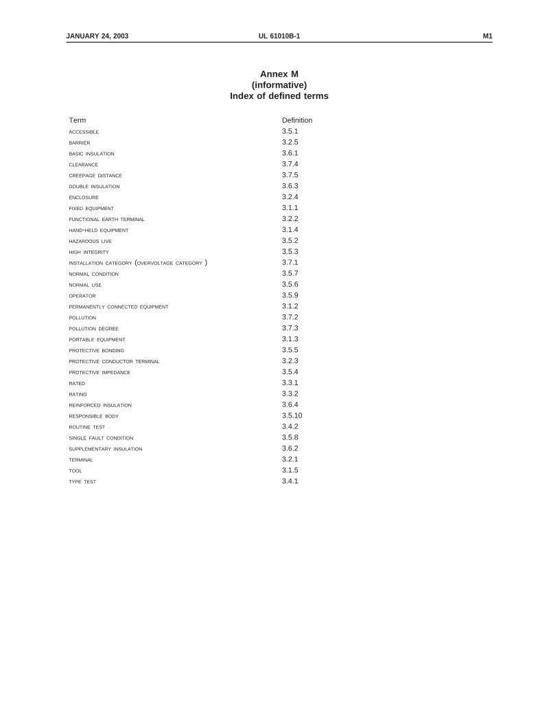
Annex M(informative)
Index of defined terms
Term Definition
ACCESSIBLE 3.5.1
BARRIER 3.2.5
BASIC INSULATION 3.6.1
CLEARANCE 3.7.4
CREEPAGE DISTANCE 3.7.5
DOUBLE INSULATION 3.6.3
ENCLOSURE 3.2.4
FIXED EQUIPMENT 3.1.1
FUNCTIONAL EARTH TERMINAL 3.2.2
HAND-HELD EQUIPMENT 3.1.4
HAZARDOUS LIVE 3.5.2
HIGH INTEGRITY 3.5.3
INSTALLATION CATEGORY (OVERVOLTAGE CATEGORY ) 3.7.1
NORMAL CONDITION 3.5.7
NORMAL USE 3.5.6
OPERATOR 3.5.9
PERMANENTLY CONNECTED EQUIPMENT 3.1.2
POLLUTION 3.7.2
POLLUTION DEGREE 3.7.3
PORTABLE EQUIPMENT 3.1.3
PROTECTIVE BONDING 3.5.5
PROTECTIVE CONDUCTOR TERMINAL 3.2.3
PROTECTIVE IMPEDANCE 3.5.4
RATED 3.3.1
RATING 3.3.2
REINFORCED INSULATION 3.6.4
RESPONSIBLE BODY 3.5.10
ROUTINE TEST 3.4.2
SINGLE FAULT CONDITION 3.5.8
SUPPLEMENTARY INSULATION 3.6.2
TERMINAL 3.2.1
TOOL 3.1.5
TYPE TEST 3.4.1
JANUARY 24, 2003 UL 61010B-1 M1

JANUARY 24, 2003UL 61010B-1M2
No Text on This Page

Annex DVA(informative)
Standards for Components
DVA D2 Addition of a new annex DVA as follows:
Standards under which components of the products covered by this standard are judgedinclude the following:
Title of Standard – UL Standard Designation
Air Filter Units –UL 900
Attachment Plugs and Receptacles –UL 498
Capacitors –UL 810
Double Insulation Systems for Use in Electrical Equipment –UL 1097
Enclosures for Electrical Equipment –UL 50
Flexible Cord and Fixture Wire –UL 62
Fuseholders –UL 512
Fuses, Low-Voltage - Part 1: General Requirements –UL 248-1
Fuses, Low-Voltage - Part 11: Plug Fuses –UL 248-11
Information Technology Equipment –UL 1950
Lampholders, Edison-Base –UL 496
Marking and Labeling Systems –UL 969
Molded-Case Circuit Breakers, Molded-Case Switches, and Circuit-Breaker Enclosures –UL 489
Motors, Electric –UL 1004
JANUARY 24, 2003 UL 61010B-1 DVA1

Motors, Overheating Protection for –UL 2111
Polymeric Materials – Use in Electrical Equipment Evaluations –UL 746C
Printed-Wiring Boards –UL 796
Sharpness of Edges on Equipment, Test for –UL 1439
Switches, Clock-Operated –UL 917
Switches, Enclosed and Dead-Front –UL 98
Switches, General-Use Snap –UL 20
Switches, Special-Use –UL 1054
Systems of Insulating Materials - General –UL 1446
Tape, Polyvinyl Chloride, Polyethylene, and Rubber Insulating –UL 510
Temperature-Indicating and -Regulating Equipment –UL 873
Terminal Blocks –UL 1059
Terminals, Electrical Quick-Connect –UL 310
Thermal Cutoffs –UL 1020
Tubing, Extruded Insulating –UL 224
Wire Connectors and Soldering Lugs for Use with Copper Conductors –UL 486A
Wire Connectors for Use With Aluminum Conductors –UL 486B
Wires and Cables, Thermoset-Insulated –UL 44
JANUARY 24, 2003UL 61010B-1DVA2

Wires and Cables, Thermoplastic-Insulated –UL 83
JANUARY 24, 2003 UL 61010B-1 DVA3

JANUARY 24, 2003UL 61010B-1DVA4
No Text on This Page