electrical measurements
TRANSCRIPT
ADMA-OPCO, Basic Training Measurements E-10 Electrical
VOCATIONAL TRAINING CENTREVOCATIONAL TRAINING CENTRE
BASIC TRAINING PROGRAMBASIC TRAINING PROGRAMElectricalElectrical
MODULE E-10
ELECTRICAL MEASUREMENTS
VTC Rev:2003 1

ADMA-OPCO, Basic Training Measurements E-10 Electrical
Electrical Instruments
While studying Electricity we come across number of quantities such as Current, E.M.F., Resistance, Power, Energy etc. Each quantity has its own unit and there should be an instrument to measure that quantity. It is clear that there are separate meters for different quantities. The entire electrical instrument is classified into 3 main types. They are :
(1) Deflecting type . These will measure the quantity and indicate the quantity on a divided scale by its pointer movement. This movement of the pointer or the detection is not constant but depends on the quantity it measures. As the needle deflects and indicates the amount of current or voltage or any quantity, these are called deflecting type of instruments.
(2) Recording type , these instruments will go on recording on a graph sheet fixed on the instrument all the variations of the quantity in the time for which it is connected in the circuit. Normally three recordings will be for one day and the recorded sheets will be kept as a record of variations of the quantity for long time.
(3) Integrating type : These are the instruments which will add up the quantity as the time passes or in other words will give a total account of the quantity spent in a given time for which it is connected in the circuit. The common example is the house service meter
(Electric meter) which will see in all the electrified houses.
The generally used deflecting type instruments in laboratories are again classified as follows:
(a) Depending on its working principle.
(b) Depending on the quantity it measures; and
(c) Depending on the Shap of the instruments.
Working principle.
Different meters will make use of different principles or effects and they are divided as normally.
(1) Moving coil,
(2) Moving iron, a- Attraction b- Repulsion
(3) Dynamo meter
(4) Hot wire
(5) Electrostatic type
(6) Induction type
VTC Rev:2003 2
ADMA-OPCO, Basic Training Measurements E-10 Electrical
Quantity. According to the quantity they measure, the meters are of the types as,
(1) Voltmeter.
(2) Ammeter.
(3) Ohmmeter.
(4) Wattmeter.
(5) Power Factor meter.
(6) Energy meter (integrating type), etc.
Shape.
Depending on the use of instruments they differ in shape. Normally, the different types are.
(1) Portable type
(2) Panel Board type:
(a) Flush mounting type
(b) Surface mounting type.
In addition to the above, while specifying an instrument there are some factors to be considered:
1. Scale (normally mentioned as 50 mm, 100 mm, 150 mm scale etc.)
2. Deflection (normally within 900 but circular scale instruments are also available which give about 2500 deflection).
3. Range of instrument – whether single range, or multirange, or center zero etc.
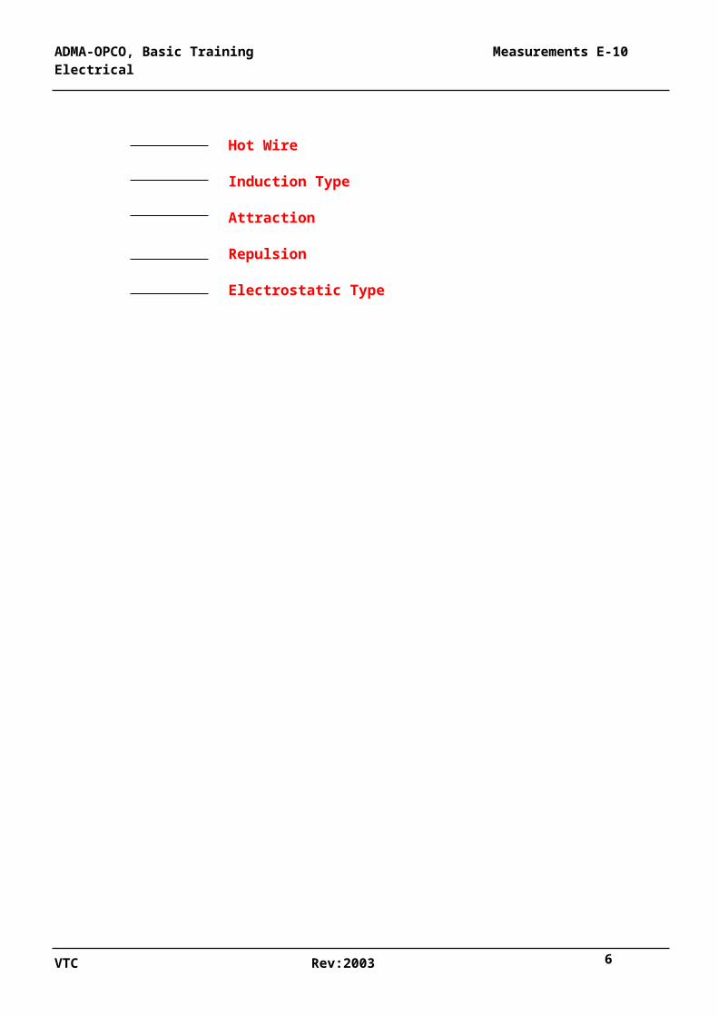
4. In case of multi-range with external resistance or internal fixing. All the deflecting instruments are marked on the scale to indicate its working principle by symbols.
VTC Rev:2003 3
ADMA-OPCO, Basic Training Measurements E-10 Electrical
ELECTRICAL INSTRUMENT
Deflecting type Recording type integrating type
Depending on it’s Depending on the Depending on working Principle quantity it measures the shape
Voltmeter Wattmeter
Ammeter Power factor meter
Ohmmeter Energy meter ( integrating type )Portable Type Panel Board Type
Flush Surface Mounting Mounting
Moving Coil
Moving Iron
Dynamo Meter
Hot Wire
Induction Type
Attraction
VTC Rev:2003 4

ADMA-OPCO, Basic Training Measurements E-10 Electrical
Repulsion
Electrostatic Type
VTC Rev:2003 5
ADMA-OPCO, Basic Training Measurements E-10 Electrical
CHAPTER 1
PRINCIPLES OF D.C. MEASUREMENT
1.1 HOT-WIRE INSTRUMENTS
Electrical quantities such as pressure (voltage) and flow (current), being invisible to the eye, can only be measured indirectly by observing their effect on other things such as a mechanical indicating system. Even in the mechanical field steam or hydraulic pressure is indicated on a pressure gauge, and flow rate or flow volume on a flowmeter.
In the electrical world the first 'indirect' means of measurement used the heating effect of a current passing through a wire. In Chapter 4 it was shown that, if a current I amperes flows through a conductor having a resistance of R ohms, then heat is generated in that conductor at the rate of I2 R watts.
This heat in the wire raises its temperature until the rate of radiation away of the heat just balances the rate of heat generation. At that point the temperature will stabilize, and it will then be a measure of the current (strictly, the square of the current) which was causing the heating.
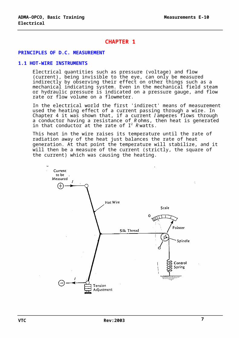
FIGURE 1.1HOT-WIRE AMMETER.
Use of this is made in the 'hot-wire ammeter' shown In Figure 1.1. A short length of platinum-iridium wire is connected electrically in series with the circuit whose current flow is to be measured. The wire is tensioned until it is fairly taut, and from its centre is taken
VTC Rev:2003 6
ADMA-OPCO, Basic Training Measurements E-10 Electrical
a silk thread tensioned by a spring and whose movement actuates a spindle to which a pointer' is fixed.
When no current flows through the main wire its tautness keeps it almost straight, and the centre thread is at its left-most position. When current flows, the temperature of the wire rises, and the wire becomes longer and slacker. The slack is taken up by the spring pulling on the centre thread and moving it to the right. In doing so the spindle is rotated clockwise, and the pointer moves over a scale.
Since any given current causes a given I2 R heating rate and therefore a given elongation of the wire and a given deflection of the pointer, for each current there is a definite position of the pointer, which depends on the square of the current. The scale can be calibrated in current units (amperes), though it will not be an even scale, being crowded at the lower end.
The instrument described is the original 'hot-wire ampere-meter' (or ammeter) and was used generally until about the turn of the century. (It is of interest that it will also indicate alternating currents
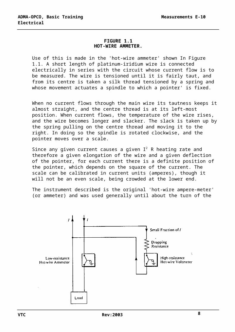
FIGURE: 1.2HOT-WIRE AMMETER AND VOLTMETER.
A similar instrument is used for indicating voltage, since, by Ohm's Law V = IR or I = V/R. If R is the resistance of the hot wire (considered fixed), then the current indicated by it will be proportional to V. In Figure 1.2 a hot-wire ammeter in series with the circuit to be measured is shown on the left, and on the right is a parallel circuit operating at the same voltage. A second hot-wire instrument is connected across this parallel circuit, but one with a high resistance in series with it. As explained above, the current, small because of the series resistance, drawn by this second instrument will still be proportional to V, and
VTC Rev:2003 7
ADMA-OPCO, Basic Training Measurements E-10 Electrical
so the instrument acts as a voltmeter and can be scaled directly in volts. It too will have an uneven scale.
1.2 MOVING-IRON INSTRUMENTS
Whereas the hot-wire instruments described above depend on the heating effect of a current for its indirect method of indicating, another class of instruments makes use of the magnetic effect of the current discovered by Oersted. Its development was largely due to Lord Kelvin.
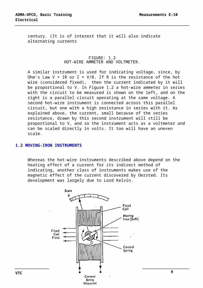
FIGURE 1.3 ..
MOVING-IRON INSTRUMENT.
Figure 1.3 shows a fixed coil through which passes the current to be measured. The coil is wound with wire of sufficient section to carry the current without overheating.
As current flows through the coil it gives rise to a magnetic field along its axis. In one form of the instrument a small piece of soft iron is pivoted so that it lies normally well across the coil's axis and is held there by a spiral control spring.
When current flows through the coil the soft iron is magnetised by induction and tries to align itself along the axis of the coil's magnetic field, but it is restrained from completely doing so by the back-pull of the spring. It takes up a balance position where the magnetic pull of the coil is just counterbalanced by the spring.
VTC Rev:2003 8
ADMA-OPCO, Basic Training Measurements E-10 Electrical
The moving-iron 'armature' is pivoted on a spindle carrying a pointer, which moves over the instrument scale. If the instrument has a low-resistance coil and is used 'in series with the circuit whose current is to be measured, it acts as an ammeter. If however it has a high- resistance coil and is used in parallel with the circuit, it acts as a voltmeter. There is otherwise no basic difference between the movements.
Some such instruments are provided with two fixed coils in parallel planes and arranged to assist each other magnetically. The moving-iron armature is then placed symmetrically on their common axis. In other makes the iron may be pivoted differently, but it always moves towards the coils' magnetic axis against some form of restraint. Various types of damping are usually added.
Because the magnetic pull of a coil on a piece of iron magnetised by induction is proportional to the square of the current, the movement of a moving-iron instrument is proportional to I2 just as was the case with the hot-wire instrument where the heating depended on I2 . The scale of a moving-iron instrument, calibrated in amperes or volts, is therefore uneven and is crowded towards the lower end. Indeed it is the crowding of the scale that makes it possible to tell a moving-iron from a moving-coil instrument at a glance.
1.3 MOVING-COIL INSTRUMENTS
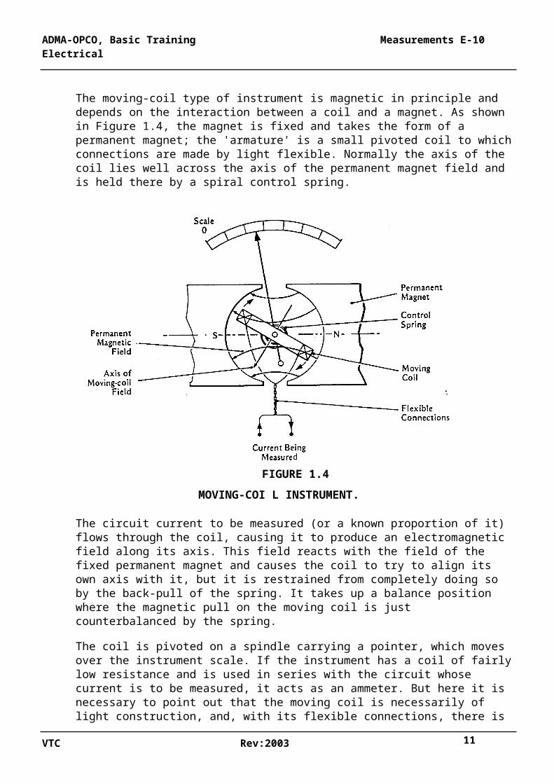
The moving-coil type of instrument is magnetic in principle and depends on the interaction between a coil and a magnet. As shown in Figure 1.4, the magnet is fixed and takes the form of a permanent magnet; the 'armature' is a small pivoted coil to which connections are made by light flexible. Normally the axis of the coil lies well across the axis of the permanent magnet field and is held there by a spiral control spring.
VTC Rev:2003 9
ADMA-OPCO, Basic Training Measurements E-10 Electrical
FIGURE 1.4
MOVING-COI L INSTRUMENT.
The circuit current to be measured (or a known proportion of it) flows through the coil, causing it to produce an electromagnetic field along its axis. This field reacts with the field of the fixed permanent magnet and causes the coil to try to align its own axis with it, but it is restrained from completely doing so by the back-pull of the spring. It takes up a balance position where the magnetic pull on the moving coil is just counterbalanced by the spring.
The coil is pivoted on a spindle carrying a pointer, which moves over the instrument scale. If the instrument has a coil of fairly low resistance and is used in series with the circuit whose current is to be measured, it acts as an ammeter. But here it is necessary to point out that the moving coil is necessarily of light construction, and, with its flexible connections, there is a limit to the size of wire that can be used. For heavier currents therefore such an ammeter would be used with a shunt (see para. 1.5). If the coil has a high resistance and is used in parallel with the circuit, it acts as a voltmeter. There is otherwise no basic difference between' the movements.
In a moving coil operating in a permanent magnet field, the magnetic pull on the coil depends only on the current in that coil, not on the square of the current as in the moving- iron type where the magnetisation is induced. Therefore the movement of the coil is almost linear with the current, and the scale of a moving-coil instrument is fairly even over its whole range, not crowded at its lower end. It is also reversible - that is, negative currents cause negative movement - and, if a 'set-up zero' is used, they can be scaled to show the reverse currents; a centre-zero ammeter is an example.
VTC Rev:2003 10
ADMA-OPCO, Basic Training Measurements E-10 Electrical
In order that a moving-coil instrument shall retain its accuracy, it is important that the permanent magnet retain its original strength and not weaken with the passage of time or with vibration or shock. Therefore the magnets used in. these instruments are made from specially chosen iron of high retentively.
Moving-coil instruments can only be used with d.c., they will not function on a.c.
1.4 DYNAMOMETER INSTRUMENTS
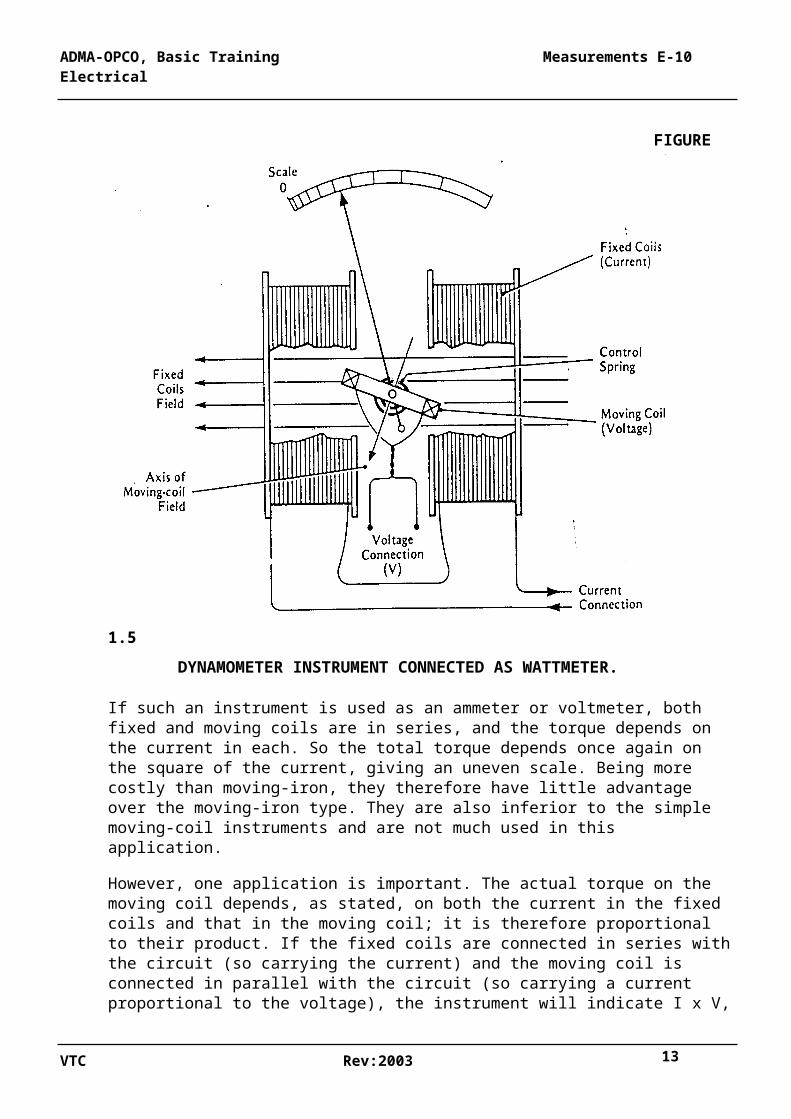
The dynamometer instrument is really a special case of the moving coil. There is a moving coil as already described, but the permanent magnet is replaced by a fixed coil (usually a pair, for reasons of symmetry, since they produce a nearly uniform field). (Figure 11.5.)
FIGURE 1.5
DYNAMOMETER INSTRUMENT CONNECTED AS WATTMETER.
VTC Rev:2003 11
ADMA-OPCO, Basic Training Measurements E-10 Electrical
If such an instrument is used as an ammeter or voltmeter, both fixed and moving coils are in series, and the torque depends on the current in each. So the total torque depends once again on the square of the current, giving an uneven scale. Being more costly than moving-iron, they therefore have little advantage over the moving-iron type. They are also inferior to the simple moving-coil instruments and are not much used in this application.
However, one application is important. The actual torque on the moving coil depends, as stated, on both the current in the fixed coils and that in the moving coil; it is therefore proportional to their product. If the fixed coils are connected in series with the circuit (so carrying the current) and the moving coil is connected in parallel with the circuit (so carrying a current proportional to the voltage), the instrument will indicate I x V, or d.c. watts. This dynamometer instrument, so connected, then becomes a wattmeter. (It is of interest that this instrument will also register a.c. watts
Since the dynamometer instrument indicates the product of V and I, then if I reverses, the torque also reverses and the instrument indicates backwards. If its zero is 'set up', it can be scaled to indicate both normal (forward) and reverse power - that is to say, it is directional.
Whenever it is desired to take direction into account (such as for some relays in protective schemes), a dynamometer or 'wattmetric' type of movement is always used.
If the currents to be measured are too high for the coils of the instrument, the series (fixed coil) current can be taken through a shunt (see para. 1.5 ), thereby using only a known proportion of the circuit current. Similarly the voltage coil (moving coil) can be fed through a 'dropping' resistance of known value, so that only a known fraction of the circuit voltage is applied.
1.5 SHUNT-CONNECTED INSTRUMENTS
Most instruments receive input from the circuit whose current is to be measured, but, due to their construction, they can in most cases accept only a small, but accurately known, proportion of that current. It is therefore necessary to divide the circuit current into two parts: the main part carrying the majority of the current, and the other part a known fraction of it - in many cases only an infinitesimal fraction, perhaps one-thousandth part.
VTC Rev:2003 12
ADMA-OPCO, Basic Training Measurements E-10 Electrical
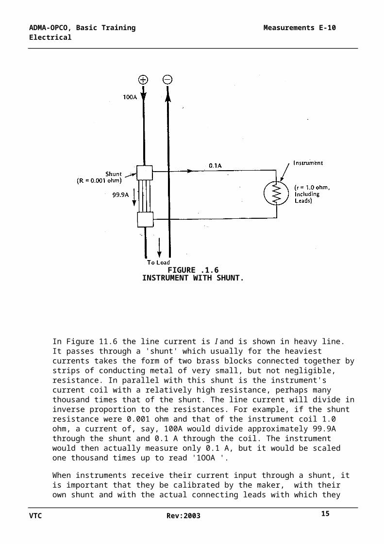
FIGURE .1.6INSTRUMENT WITH SHUNT.
In Figure 11.6 the line current is I and is shown in heavy line. It passes through a 'shunt' which usually for the heaviest currents takes the form of two brass blocks connected together by strips of conducting metal of very small, but not negligible, resistance. In parallel with this shunt is the instrument's current coil with a relatively high resistance, perhaps many thousand times that of the shunt. The line current will divide in inverse proportion to the resistances. For example, if the shunt resistance were 0.001 ohm and that of the instrument coil 1.0 ohm, a current of, say, 100A would divide approximately 99.9A through the shunt and 0.1 A through the coil. The instrument would then actually measure only 0.1 A, but it would be scaled one thousand times up to read '1OOA '.
When instruments receive their current input through a shunt, it is important that they be calibrated by the maker, with their own shunt and with the actual connecting leads with which they will eventually be installed. Because of the great disparity between the resistance of the shunt itself and of the parallel instrument circuit, small errors in the latter could cause considerable errors in the instrument reading; hence the need to calibrate all together.
When an instrument is being installed with its shunt, the leads must never be altered or shortened; any extra length must be left in and flaked out. Shunt-operated instruments
VTC Rev:2003 13
ADMA-OPCO, Basic Training Measurements E-10 Electrical
should all be marked with their associated shunt serial number and used with no other. For example, in the case quoted, one-tenth of an ohm cut out of the shunt leads would lead to a 10% error in the instrument's reading.
1.6 TERMINOLOGY
The words used with indicating instruments and similar devices are often misused, and below is a summary of the terms and their correct usage:
'Indicating Instrument' or simply 'Instrument'. An indicating device to show the instantaneous value of the quantity being measured. Note that, although the terms 'voltmeter', 'ammeter', 'wattmeter' etc. are generally used, the generic term 'meters' should never be used for indicating instruments.
'Integrating Meter'. A device for integrating a quantity over a period of time, Usually associated with watts and vars, the total quantity shown by dial or digital,' as watt-hours (Wh) or var-hours (varh). Such integrating device are known collectively as 'meters' (as distinct from 'instruments' above). :
'Recording Instrument'" or 'Recorder'. A device for continuously recording the instantaneous value of a quantity, the record being made by pen-on-paper or similar device, or digitally on paper or tape.
'Set-up Zero'. When an instrument is carrying no current, the position taken up by its pointer under the influence of the control spring is its 'zero'"and it is usually at the ex treme left-end of the scale. However, instruments can be arranged so that the zero is not at the extreme end but at some distance to the right; it is then said to have a 'set-up zero', This allows the instrument to register, in part at least, in the negative or reverse direction. It can only be applied to moving-coil or dynamometer instruments, A center-zero ammeter showing battery charge and discharge is an example of a setup zero.
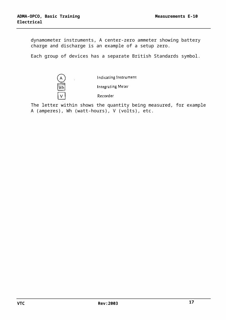
Each group of devices has a separate British Standards symbol.
The letter within shows the quantity being measured, for example A (amperes), Wh (watt-hours), V (volts), etc.
VTC Rev:2003 14
ADMA-OPCO, Basic Training Measurements E-10 Electrical
CHAPTER 2-
PRINCIPLES OF A.C. MEASUREMENT
2.1 USE OF D.C. INSTRUMENTS FOR A.C.
Different types of instrument used for d.c. measurements. They are the hot-wire, moving- iron, moving-coil and dynamometer types and are there described and illustrated in detail.
Some of them may also be used for a.c. measurements, and each is considered below in that application.
2.2 HOT-WIRE INSTRUMENTS
This instrument depends for its action on the heating and stretching of a wire due to the passing of current through it. The heating with a D.C. current is at the rate I2 R, where R is the resistance of the internal hot wire. But with a.c. the heating is also at the rate I2 R provided that I is the rms current - indeed, it has been shown that rms current is defined as that a.c. current which produces the same heating as a d.c. current, of the same numerical value.
Consequently a hot-wire instrument to which a.c. is applied will correctly indicate the rms value of the applied quantity.
FIGURE2.1
VTC Rev:2003 15
ADMA-OPCO, Basic Training Measurements E-10 Electrical
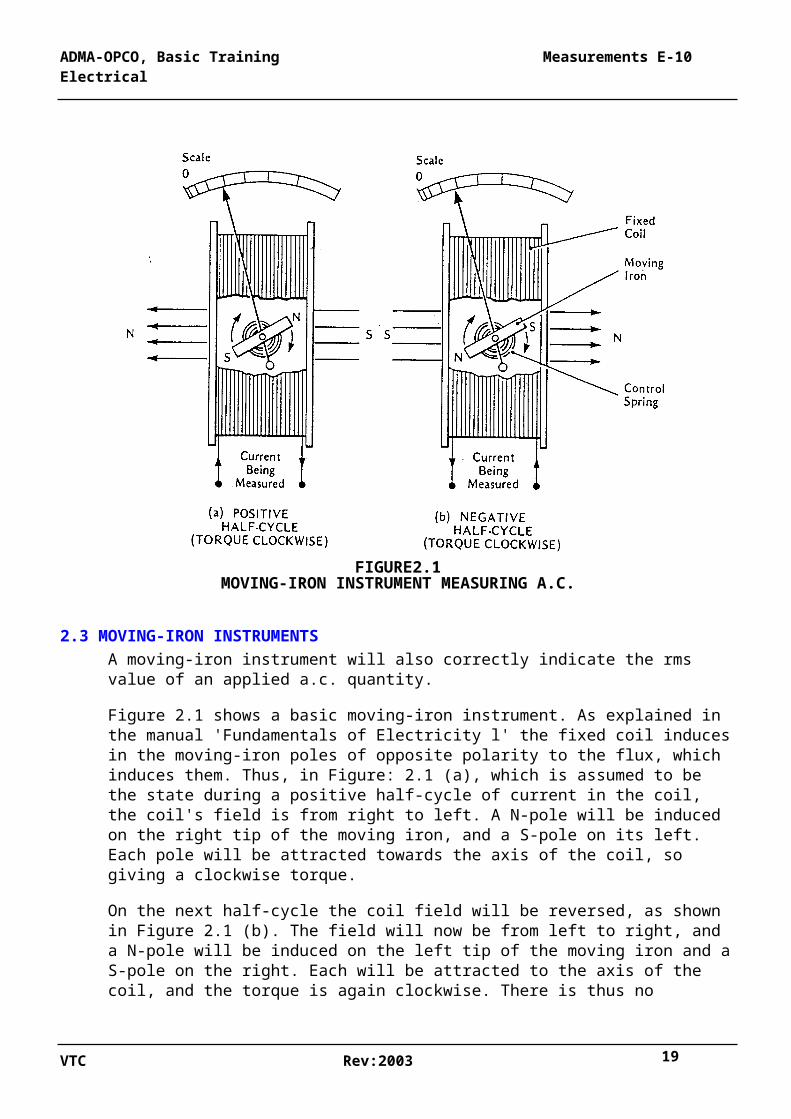
MOVING-IRON INSTRUMENT MEASURING A.C.
2.3 MOVING-IRON INSTRUMENTS
A moving-iron instrument will also correctly indicate the rms value of an applied a.c. quantity.
Figure 2.1 shows a basic moving-iron instrument. As explained in the manual 'Fundamentals of Electricity l' the fixed coil induces in the moving-iron poles of opposite polarity to the flux, which induces them. Thus, in Figure: 2.1 (a), which is assumed to be the state during a positive half-cycle of current in the coil, the coil's field is from right to left. A N-pole will be induced on the right tip of the moving iron, and a S-pole on its left. Each pole will be attracted towards the axis of the coil, so giving a clockwise torque.
On the next half-cycle the coil field will be reversed, as shown in Figure 2.1 (b). The field will now be from left to right, and a N-pole will be induced on the left tip of the moving iron and a S-pole on the right. Each will be attracted to the axis of the coil, and the torque is again clockwise. There is thus no reversal of torque as between positive and negative half-cycles, and the pull will be always in the same direction.
The magnitude of the magnetic pull between a coil and its induced magnetic pole is proportional to the product of the coil's flux (and so the current in it) and of the strength of the induced pole. But that strength is itself proportional to the flux causing it, so the total pull - and hence the torque on the moving iron - is proportional to the square of the coil current.
Therefore, like the hot-wire type, the moving-iron instrument responds not simply to the current but to the square of the current. Its scale will be uneven and crowded towards the lower end, and it will indicate the rms value of the current being measured. Moving-iron instruments are relatively cheap and are widely used ashore and in platforms on a.c. switch- boards. They can be instantly recognized by their scales.
1.4 MOVING.COIL INSTRUMENTS.
Moving-coil instruments cannot be used with a.c. for the following reason:
Figure 2.2 is a reproduction of the corresponding moving-coil figure in the DC As explained there, a permanent magnet provides a constant field in which a moving coil rotates. In the figure the N-pole is assumed to be on the right, and the field in the gap is therefore from right to left.
VTC Rev:2003 16
ADMA-OPCO, Basic Training Measurements E-10 Electrical
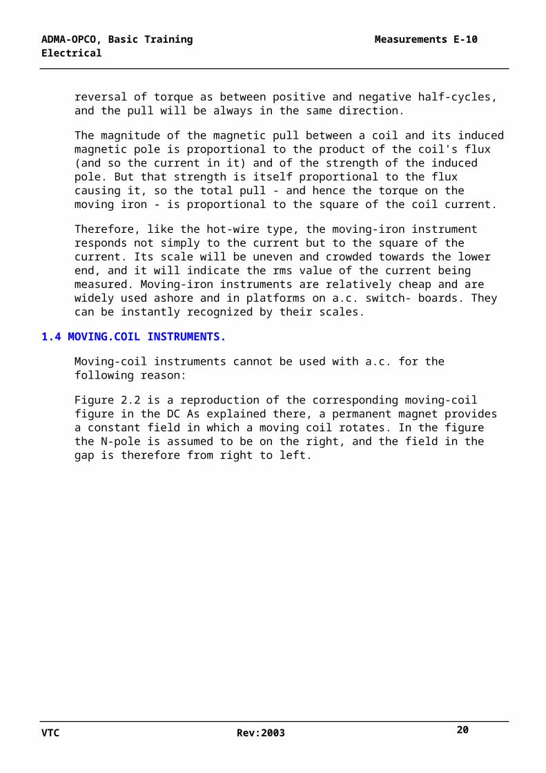
FIGURE2.2MOVING-COIL INSTRUMENT ATTEMPTING TO MEASURE A.C.
The current to be measured flows through the moving coil and gives rise to its own flux. This flux reacts with the permanent field and causes a torque on the moving coil. The coil turns against a control spring so as to try to align its own axis with that of the permanent magnet. This is shown in Figure 2 .2(a), which is assumed to be the state during a positive half-cycle of current .in the moving coil. The coil's 'S' side is attracted towards the magnet's N-pole, and its 'N' side to the magnet's S-pole, so producing a clockwise torque.
Half a cycle later the coil current is reversed, as shown in Figure 2.2(b), but the direction of the permanent magnet field is unchanged. The coil's "N' side is now on top and is repelled by the magnet's N-pole, just as its 'S' side is repelled by the magnet S pole. The two combine to produce an anti-clockwise torque.
The direction of torque thus reverses with every half-cycle, and, because of the inertia of the movement, no motion whatever takes place (though there might be a buzz). For this reason moving-coil instruments cannot be used directly on a.c., although they can be used with transducers (see para. 2.6).
VTC Rev:2003 17
ADMA-OPCO, Basic Training Measurements E-10 Electrical
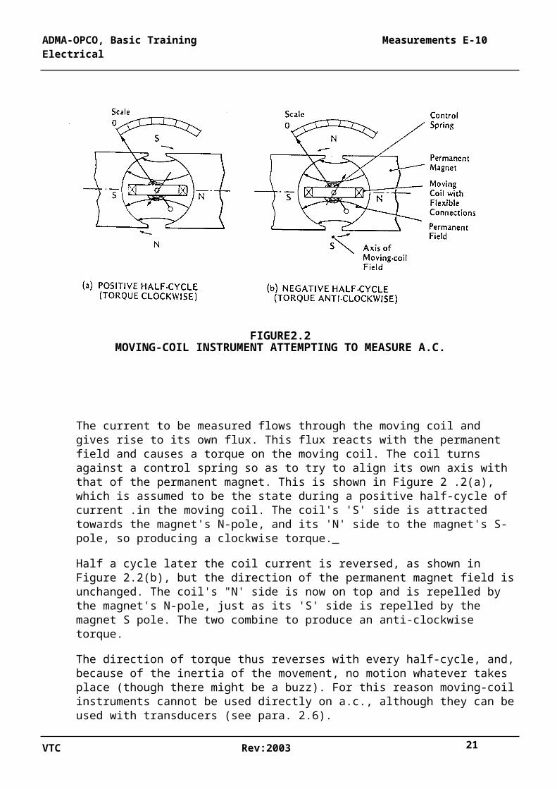
2.5 DYNAMOMETER INSTRUMENTS
A dynamometer instrument consists of fixed coils and a moving coil.
When used as an ammeter or voltmeter (rarely done), the fixed and moving coils are in series or parallel respectively, and therefore both fixed and moving fluxes reverse together with each half-cycle. Therefore there is no change in the direction of torque, and the pull is always one way, as shown in Figure.3.
FIGURE 2.3DYNAMOMETER INSTRUMENT USED AS AN A.C. WATTMETER.
Moreover, since the torque depends on the product of the currents in both the fixed and moving coils, and since these are either equal (in an ammeter, where they are in series) or proportional (in a voltmeter, where they are in parallel, the torque proportional to the square the coil current. The instrument will therefore have an uneven scale and will indicate rms current or voltage. Dynamometer instruments can consequently be used as ammeters or voltmeters on an a.c. system, where they will indicate rms values, although, as already said, this is not often done' because of cost. The dynamometer instrument is however principally used as a wattmeter, where the fixed coils carry the line current and the moving coil the line voltage. Here again when
VTC Rev:2003 18
ADMA-OPCO, Basic Training Measurements E-10 Electrical
going from a positive to negative half-cycle, both change sign together, so that there is no reversal of torque. The magnitude of the torque depends on the product of the voltage (moving) field strength, of the current (fixed) field strength and of the cosine of the phase angle between them. The torque therefore is proportional to VI cos Ø. But cos Ø is the power factor, so the torque is proportional to the active power in watts. The dynamometer instrument can consequently be used as an a.c. wattmeter. This instrument can also be adapted for 3-phase working, where, by suitable connections between the phases, it can be made to indicate the total watts in a balanced or an unbalanced 3-phase system. By suitable reconnections between the phases the same instrument can be made to indicate VI sin Ø - that is, reactive power, and so is used as a varmeter.
2.6 TRANSDUCER-OPERATED INSTRUMENTS
There are in big installations many disadvantages in carrying the signals (especially currents) from the sensing devices over long distances to a control centre. Also wattmeters and similar instruments of the dynamometer type are expensive, Much cost can be saved and the instrumentation simplified if all a.c. measurements could be converted to simple equivalent d.c. voltages proportional to the quantities sensed, and the d.c. Signals so derived distributed to all control points in parallel and displayed on simple D.C. moving-coil voltmeters. The scale would of course not be in d.c. volts, but it would be calibrated in whatever unit the original sensing device was measuring. This may be volts, amperes, watts, hertz (frequency), power factor or any other quantity. The, sensing device, most usually a current transformer or voltage transformer (see para. 2.8), feeds its signal into a solid-state electronic circuit where the signals are processed, converted to d.c. exactly proportional to the quantity sensed and passed out as a variable- voltage d.c. signal to be displayed on voltmeters wherever desired. Such an electronic device is called a 'transducer'; it is relatively cheap and may be incorporated inside the instrument, or it may be in a separate box near to the sensing point when remote instruments need to be connected to the d.c. side.
2.7 INDUCTION (EDDY-CURRENT) INSTRUMENTS
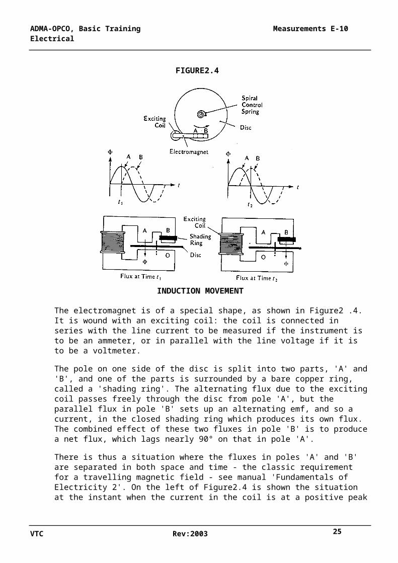
There is another class of instrument which works on a totally different principle and which operates only with alternating current. They are 'induction' instruments, also called 'eddy- current' type, as shown in Figure2.4. The movement consists of a thin copper or aluminium disc which is caused to rotate between the poles of a special electromagnet. As it rotates it winds up a spiral control spring, which opposes the rotation increasingly as the disc moves.
VTC Rev:2003 19
ADMA-OPCO, Basic Training Measurements E-10 Electrical
FIGURE2.4
INDUCTION MOVEMENT
The electromagnet is of a special shape, as shown in Figure2 .4. It is wound with an exciting coil: the coil is connected in series with the line current to be measured if the instrument is to be an ammeter, or in parallel with the line voltage if it is to be a voltmeter.
The pole on one side of the disc is split into two parts, 'A' and 'B', and one of the parts is surrounded by a bare copper ring, called a 'shading ring'. The alternating flux due to the exciting coil passes freely through the disc from pole 'A', but the parallel flux in pole 'B' sets up an alternating emf, and so a current, in the closed shading ring which produces its own flux. The combined effect of these two fluxes in pole 'B' is to produce a net flux, which lags nearly 90° on that in pole 'A'.
There is thus a situation where the fluxes in poles 'A' and 'B' are separated in both space and time - the classic requirement for a travelling magnetic field - see manual 'Fundamentals of Electricity 2'. On the left of Figure2.4 is shown the situation at the instant when the current in the coil is at a positive peak (time t1). The flux in pole 'A' is maximum (downwards, say), and the flux in pole 'B' is zero.
One-quarter of a cycle later (time t2, right-hand side of Figure2.4) the flux in pole' A' is zero and the flux in pole 'B', which lags 90° on that in pole 'A', is now maximum positive. So the peak flux has moved from 'A' to 'B' in one-quarter of a cycle - it has, in fact, traveled from 'A' to 'B'.
VTC Rev:2003 20
ADMA-OPCO, Basic Training Measurements E-10 Electrical
As a flux wave travels, it induces in the metal disc a mass of so-called 'eddy currents' - local whirls of current within the disc which react with the travelling field and, as explained in the manual 'Fundamentals of Electricity l' for the interaction of currents in a magnetic field, produce a mechanical force on the outside of the disc, causing it to try to follow the travelling field. The disc therefore undergoes a torque, which is proportional to the travelling flux and so to the square of the current in the coil.
Under this torque the disc starts to rotate, and as it does so it begins to wind up the spiral spring. This continues until the torque exerted by the spring exactly balances the driving torque due to the travelling field of the magnet; the disc then comes to rest.
The rest position is thus an indication of the current in the coil, and the disc actuates a pointer, which moves over a scale, which is calibrated in amperes or volts. Since the torque is proportional to the square of the current, this type of instrument, like the moving-iron type, has a non-linear scale and is calibrated to read rms values.
One distinguishing feature of the induction-type instrument is that the disc has a far greater range of movement than is possible in the moving-iron type, and the scale is therefore very long, or open, covering almost the whole of the face of the instrument.
Induction instruments are now not much used as ammeters or voltmeters, as the moving- iron type is much cheaper, but the method is used with integrating meters such as .the kWh meter found in domestic and other installations. In that application there are two coils, one voltage and one current, on either side of the disc. There is no spiral spring but instead a brake magnet, which controls the disc speed. The torque is then proportional to the product of the voltage flux, of the current flux and of the cosine of the phase angle between them, namely:
This instrument's disc therefore moves, controlled by the brake magnet, at a speed proportional to the active power, watts. Having no control spring it does not stop but continues to rotate, operating a counter as it does so; this indicates the watt-hours (or kWh) which have been consumed by the circuit over any period of time. I t is thus an integrating meter, in that it continuously adds up the energy consumed.
The induction, or eddy-current, movement is also widely used in overcurrent relays (see manual 'Electrical Control Devices'), where the method is the same as for the watt-hour meter as described, but the disc, after rotating through a preset angle, strikes an adjustable contact. The time, which elapses before this happens depends on the speed of the disc, and so on the line current causes it. A variable time delay can therefore be set on this relay, depending on the current being measured and by varying the distance to be traveled by the disc before striking the contact.
VTC Rev:2003 21
ADMA-OPCO, Basic Training Measurements E-10 Electrical
2.8 INSTRUMENT TRANSFORMERS
The current, or voltage, in the operating coil of any type of a.c. instrument could be the actual line current or voltage of the system. However, in most a.c. systems the operating voltages are very high and the currents are large. Severe practical difficulties would arise if such voltages were applied to these small instruments or switchboards, or if they had to be designed to carry such heavy currents.
It is therefore universal practice to apply the operating voltage through a step-down 'voltage transformer' or to apply the operating current through a step-down 'current transformer'. In either case a much lower voltage or current, which is an exact proportion of the line voltage or current, is applied to the instrument. The scale however is calibrated to read the actual line values, not the ones actually applied.
These 'instrument transformers' are described more fully in the manual 'Electrical Protection.
VTC Rev:2003 22
ADMA-OPCO, Basic Training Measurements E-10 Electrical
CHAPTER 3
A.C. MEASUREMENTS
4.1 GENERAL
In a.c. power systems it is necessary continually to monitor the voltage, currents, power and similar quantities in the various parts of the system. This is done by the use of instruments - that is by indicating voltmeters, ammeters, wattmeters etc. The same measured quantities are also used to protect the system by means of relays, which are devices to detect when any of the quantities is going outside the predetermined limit. They initiate whatever automatic action is necessary to restore the situation or disconnect faulty or overloaded apparatus.
Almost all electrical instruments and relays depend for their action on measurements of voltage or current or combinations of the two. Measurements of frequency are obtained from analyzing a voltage measurement.
The manner in which the various types of a.c. measuring instruments work is described in Chapter 8 of the manual 'Fundamentals of Electricity 3'. These include moving-iron, dynamometer and eddy-current types and also transducer-operated instruments. In the following paragraphs it will be assumed that the appropriate type of instrument is used.
VTC Rev:2003 23
ADMA-OPCO, Basic Training Measurements E-10 Electrical
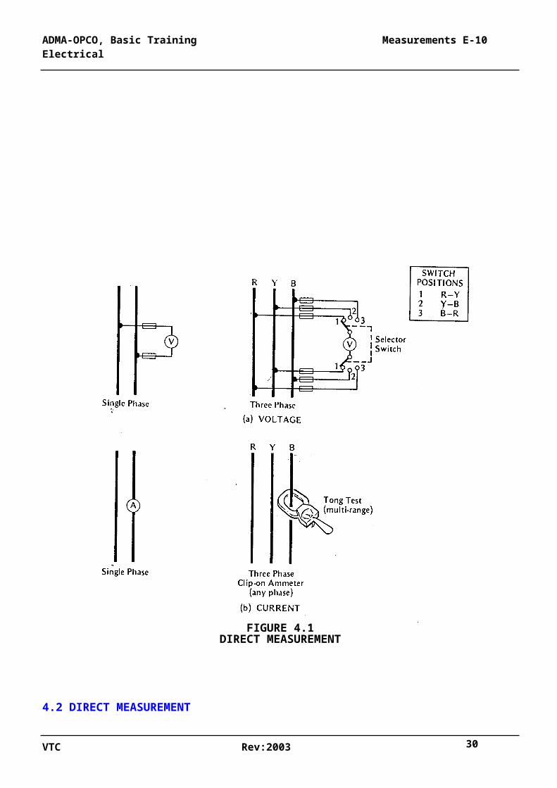
FIGURE 4.1DIRECT MEASUREMENT
4.2 DIRECT MEASUREMENT
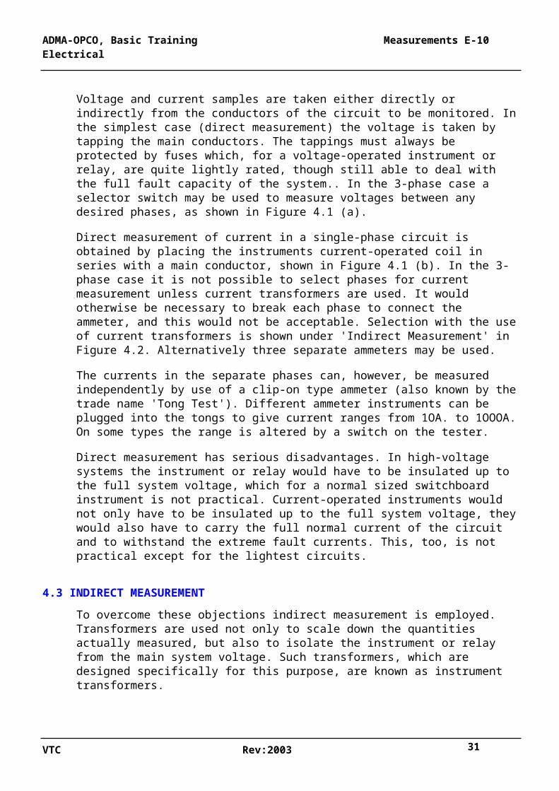
Voltage and current samples are taken either directly or indirectly from the conductors of the circuit to be monitored. In the simplest case (direct measurement) the voltage is taken by tapping the main conductors. The tappings must always be protected by fuses which, for a voltage-operated instrument or relay, are quite lightly rated, though still able to deal with the full fault capacity of the system.. In the 3-phase case a selector switch may be used to measure voltages between any desired phases, as shown in Figure 4.1 (a).
VTC Rev:2003 24
ADMA-OPCO, Basic Training Measurements E-10 Electrical
Direct measurement of current in a single-phase circuit is obtained by placing the instruments current-operated coil in series with a main conductor, shown in Figure 4.1 (b). In the 3-phase case it is not possible to select phases for current measurement unless current transformers are used. It would otherwise be necessary to break each phase to connect the ammeter, and this would not be acceptable. Selection with the use of current transformers is shown under 'Indirect Measurement' in Figure 4.2. Alternatively three separate ammeters may be used.
The currents in the separate phases can, however, be measured independently by use of a clip-on type ammeter (also known by the trade name 'Tong Test'). Different ammeter instruments can be plugged into the tongs to give current ranges from 1OA. to 1OOOA. On some types the range is altered by a switch on the tester.
Direct measurement has serious disadvantages. In high-voltage systems the instrument or relay would have to be insulated up to the full system voltage, which for a normal sized switchboard instrument is not practical. Current-operated instruments would not only have to be insulated up to the full system voltage, they would also have to carry the full normal current of the circuit and to withstand the extreme fault currents. This, too, is not practical except for the lightest circuits.
4.3 INDIRECT MEASUREMENT
To overcome these objections indirect measurement is employed. Transformers are used not only to scale down the quantities actually measured, but also to isolate the instrument or relay from the main system voltage. Such transformers, which are designed specifically for this purpose, are known as instrument transformers.
Instrument transformers are of two types - 'voltage transformers' (VT) and 'current transformers' (CT). They are shown diagrammatically in figure 4.2 for both single-phase and 3-phase systems. For 3-phase there may be either three separate single-phase VTs (with their ratios adjusted for the star connection) as shown in the inset to the figure, or else a 3-phase unit, which is more usual. Current transformers are always provided as separate single-phase units.
The secondary voltages and currents may be chosen as desired, but in practice the VT secondary voltage is usually 11OV line-to-line, and the CT secondary Current 5A or 1 A (see para. 4.7 for special caution when dealing with CT secondaries).
To select the phases between which voltages are measured, a 3-position selector switch is used, as in Figure 4.1, but connected to the VT secondaries. Further positions may be provided to measure voltages between each phase and neutral.
To select the phases in which currents are measured, a special selector switch is used which inserts the ammeter into the CT secondary of the desired phase and at the same time allows the secondary currents of the other two phases to pass. To avoid open-circuiting the CT secondaries, all contacts are of the make-before-break type. This is shown in Figure 4.2(b), bottom right.
VTC Rev:2003 25
ADMA-OPCO, Basic Training Measurements E-10 Electrical
FIGURE 4.2INDIRECT MEASUREMENT WITH INSTRUMENT TRANSFORMERS
A VT feeds, through secondary fuses (except in the earthed line), all voltage-operated instruments and relays in parallel, single- or 3-phase as required. Current-operated instruments and relays are connected in series with the CT secondary whose phase is being used. Fuses must never be used in a CT secondary circuit, for the reason stated in par 4.7.
Instrument transformer secondaries must always be earthed. With star-connected VT secondaries it is normal practice to earth one phase (usually the yellow) and not the star-point. CT secondaries are normally commoned at some point, and it is usual to earth this common line, as shown in Figure 4.2(b).
VTC Rev:2003 26
ADMA-OPCO, Basic Training Measurements E-10 Electrical
4.4 INSTRUMENT ACCURACY
Since the purpose of instruments and relays is to monitor the actual conditions in the main power line, it is necessary that VTs and CTs reproduce those conditions, to a stepped-down scale, as accurately as possible. That is to say their voltage ratio or current ratio must be correct and constant over their whole range of operation; they must not introduce undue phase shift while doing so (important for wattmeters); and they must reproduce unbalance conditions exactly.
The extent to which these conditions are met determines the accuracy class of the instrument transformer. A distinction is drawn between 'measuring' and 'protective' types. For measurements, the accuracy within, and a little above, the normal working range is important, but accuracy in the overcurrent and fault ranges of current does not matter. On the other hand, a protective CT must deliver accurate currents in the fault range, whereas accuracy in the working range is unimportant. This gives rise to two different design concepts.
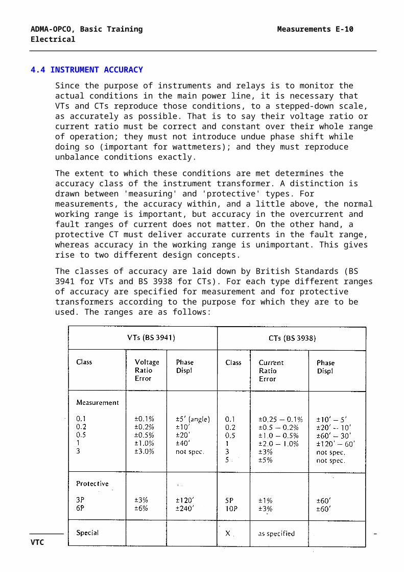
The classes of accuracy are laid down by British Standards (BS 3941 for VTs and BS 3938 for CTs). For each type different ranges of accuracy are specified for measurement and for protective transformers according to the purpose for which they are to be used. The ranges are as follows:
(Note: These classifications replace the former A-B-C series which is, however, still found on equipment installed before the change.)
VTC Rev:2003 27
ADMA-OPCO, Basic Training Measurements E-10 Electrical
Most indicating instruments on onshore and offshore switchboards are fed from VTs and CTs of Class 0.5, and most protective relays from VTs Class 3P and CTs Class 5P. There are, however, exceptions (for example differential relays are fed from Class X CTs), and it is necessary to refer to drawings for particular cases.
If it is ever necessary to check or recalibrate a switchboard instrument or relay, it must always be done with instrument transformers of a class higher than those with which it normally runs.
4.5 VOLTAGE TRANSFORMER DESIGN
A voltage transformer is made basically like an ordinary open-type power transformer, with separate HV and LV windings. It is, of course, much smaller, having ratings in the range 15 to 200VA per phase. The loading on a VT (or CT) is termed 'burden', not 'load'; an instrument transformer burden is always measured in volt-amperes, never in watts. At voltages up to those found in Shell installations, VTs are always dry-type, often embedded in synthetic resin. They are usually located inside the switchboards. On shore equipments, especially when associated with high-voltage oil circuit-breakers, VTs are often in oil-filled tanks (see Figure 2.1 of Part A of this manual.
The high-voltage VT primary fuses are of the HRC type. They have a low current rating but are capable of breaking the full busbar fault current of the HV system. They are located in the VT compartment and with some types are embodied in the VT itself.
Access to the high-voltage VT and its fuses is through the VT compartment door. This cannot be opened until the VT has been isolated. The manner of isolation varies with different manufacturers.
4.6 CURRENT TRANSFORMER DESIGN
A current transformer can take one of two forms. One type is wound like an ordinary transformer, with primary and secondary windings round a common core. As a CT steps current down, it steps voltage up. The primary winding, though connected in the system's high-voltage system, is in. fact the LV (high current) winding as far as the transformer is concerned, and the secondary is the HV (low current) winding. Wound-primary CTs are used where the primary current is low and where it is necessary to have several primary turns to achieve enough ampere-turns in the CT. The examples shown in Figure 4.3(a) and (b) are typical; burdens are in the range 5 to 30V A per phase. Wound-primary CTs must be able to withstand the full voltage and fault current of the main system on their primary windings.
VTC Rev:2003 28
ADMA-OPCO, Basic Training Measurements E-10 Electrical
FIGURE 4.3
TYPICAL CURRENT TRANSFORMERS
An alternative form of CT is known as the 'bar' or 'ring' type. It has no primary 'winding' as such but uses the main conductor itself as a 'one-turn' primary. The flux surrounding the conductor, due to the current it is carrying, links the closed iron core of the CT and induces voltage in the secondary winding, which is wound as a toroid around the circular core. The secondary circuit is closed through its burden, and the current, which flows in it is an exact scaled-down replica of the primary current in the conductor.
Bar-type CT is generally used whenever the current ratio (e.g. 1500/1 A) is large enough. They are also convenient in that several can easily be stacked over a single existing conductor. It is very important that they are placed the right way up, otherwise the secondary terminal voltages and current flow will be reversed. By convention the secondary terminal S1 always has the same polarity as primary terminal P1, or as that of the end of the bar emerging from the face marked P1. This type of CT is shown in Figure 4.3(c). Its construction is not limited by the fault current of the main system.
Another important difference between a CT and other types of transformer lies in its magnetisation. The magnetising current, and therefore the flux, of a power transformer or a VT is constant and depends only on the applied voltage. However a CT when it has no burden is effectively short-circuited, and no voltage is present, whatever the primary current; there- fore there is no core flux. If the burden is increased, so also is the voltage
VTC Rev:2003 29
ADMA-OPCO, Basic Training Measurements E-10 Electrical
for a given current, as explained in para. 4.7, and this causes the magnetisation to increase. Thus with a current transformer the magnetisation is variable not only with the current, but it also is increased depending on the burden connected. -.
In the limit, if the burden is increased beyond the rating of the CT, the core will saturate, and the current ratio of the CT will no longer hold; it will become inaccurate. Moreover the iron losses will rise sharply and may cause severe overheating of the CT and possibly damage to it.
4.7 SPECIAL DANGERS WITH CURRENT TRANSFORMERS
When a CT secondary circuit is closed, current flows through it, which is an exact proportion of the primary current, regardless of the resistance of the burden. In Figure 4.4(a) the secondary of the CT (assumed to have a ratio of 1OOO/5A and to have 1OOOA flowing in the primary) is carrying exactly 5A, and, since the secondary terminals S1 and S2 are short- circuited, there is no voltage between them.
If now the short-circuit be replaced by a resistance of, say, 0.5 ohm (as in Figure 4.4(b)), the same 5A will flow through, causing a volt-drop of 2.5V and a burden of 5 x 2.5 = 12.5V A. If the resistance were increased to 5 ohms (as in Figure 4.4(c)), the terminal voltage with 5A flowing would rise to 25V and the burden to 125V A. The greater the resistance, the greater would be the voltage and burden until, as it approached infinity (the open-circuit condition), so also in theory would the voltage (and burden) become infinite. This cannot of course happen in practice because the CT would saturate or the terminals flash over due to the very high secondary voltage between them. But it does show the danger of open-circuiting the secondary of a running CT. lethal voltages can be produced at the point of opening. This is why CT secondaries are never fused.
The danger from an open-circuited CT is twofold. It can produce lethal voltages and so is a very real danger to personnel. The high voltage across the secondary winding could also cause insulation failure in that winding, leading at best to inaccuracy and at worst to burn- out or fire.
Before ever an instrument or relay is removed from the secondary loop of a running CT (if such a thing had to be done), the wires feeding that instrument must first be securely short- circuited at a suitable terminal box or, better, at the CT itself. Similarly, if a running CT is ever to be taken out of circuit, it must first be firmly shorted. CTs with 1 A secondaries are more dangerous than those with 5A, as the induced voltages are higher.
VTC Rev:2003 30
ADMA-OPCO, Basic Training Measurements E-10 Electrical
FIGURE 4.4VOLTAGE AND BURDEN OF A CURRENT TRANSFORMER
To prevent this danger many CT secondaries are permanently short-circuited by a 'metrosil', which is a. non-linear element with a high resistance at low voltages but which breaks down to almost' a short-circuit at the higher and dangerous voltages. It does, however, somewhat reduce the accuracy of the CT and is not always acceptable for this reason.
There is also a range of CTs designed to saturate if their burden becomes excessive, so that even on open-circuit their secondary voltage will not exceed about 100V. It is not safe, however, to assume that such CTs are fitted in any particular case.
VTC Rev:2003 31

ADMA-OPCO, Basic Training Measurements E-10 Electrical
WARNING
WHENEVER POSSIBLE THE MAIN CIRCUIT SHOULD BE MADE DEAD BEFORE INTERFERING WITH CT SECONDARIES OR THEIR INSTRUMENTS OR RELAYS
4.8 CALCULATION OF AN INSTRUMENT TRANSFORMER BURDEN
Instrument transformers are rated according to the burden that they can carry and still remain within their specified accuracy. The burdens are always given in VA units (i.e. power factor is ignored), and all burdens are simply added together. Manufacturers of instruments and relays similarly state the burdens of these devices in VA. Thus, if a CT operates an ammeter (2VA). a current relay (3VA) and, say, the current coil of a kWh meter (4VA), the total burden on the CT of these three devices will be 9VA.
The burden imposed by long secondary pilot leads, however, cannot be ignored. If, for example, the total resistance of a CT secondary run were 0.5 ohms (go and return) and the CT had a 5A secondary, the total volt-drop across the pilots would be 0.5 x 5 = 2.5V. With 5A current flowing in them, the burden of the pilot leads would be 2.5V x 5A = 12.5V A, and this would need to be added to that of the instruments (9VA above) to give a total burden on the CT of 12.5 + 9 = 21.5VA. It must therefore have a rating sufficient to meet this total burden. In general, pilot leads impose far less VA burden on a 1 A current transformer than on a 5A.
FIGURE 4.5CALCULATION OF CT BURDEN
In Figure 4.5 a 20VA CT with full-load secondary current of 5A supplies two ammeters, a current relay, a wattmeter and a kWh meter with VA burdens as shown. The pilot leads have a resistance of 0.1 ohm per core. Is the 20VA rating of the CT sufficient?
Total instrument burden = 2 + 2 + 3 + 2 + 4 = 13V A. Total pilot load resistance = 2 x 0.1 = 0.2 ohm. With 5A secondary current, volt-drop in leads is 5 x 0.2 = 1 V.
VTC Rev:2003 32

ADMA-OPCO, Basic Training Measurements E-10 Electrical
Burden imposed by both leads = 5A x 1 V = 5V A. Total burden on CT = 13 + 5 = 18V A.
As the CT is rated 20V A, it has sufficient margin.
The reader should work out for himself what would be the total burden if the CT had a 1 A secondary.
4.9 LOCATION OF CTs AND VTs
Current and voltage transformers can be located anywhere desired where the primary conductors are available, but in HV switchgear they are usually incorporated in special chambers in the switchgear unit itself. Figures 3.1 and 3.3 in Part A of this manual show views of typical HV circuit-breaker units, where the VT and CT chambers can be clearly seen. The VT can be drawn forward to isolate it from the busbars. Other manufacturers' arrangements differ in detail, especially in the front or back access to the VT chamber.
4.10 INSTRUMENTS
A.C. instruments include voltmeters, ammeters, wattmeters, varmeters, power factor meters, frequency meters and synchroscopes. Voltmeters, ammeters and frequency meters are almost all of the moving-iron or transducer-operated type, with an accuracy of 2% full-scale deflection. Wattmeters and varmeters are of the dynamometer type, and power factor meters and synchroscopes have two sets of fixed coils and a moving-iron armature. All voltage-operated coils (except those for 415V or 440V or less which may be direct-fed) are fed through VTs, and all current-operated coils through CTs at all voltages.
4.11 EXAMPLE - INSTRUMENTATION FOR A GENERATOR
Figure 4.6 shows a typical set of instrumentation for an offshore high-voltage generator. One complete set of indicating instruments is normally located on the electrical control panel in the Electrical Control Room; a second set is mounted on the generator local control panel. A megawatt meter for each generator may also be mounted on the main control panel in the Platform Control Room if this is separate from the Electrical Control Room. The generator circuit-breaker panel usually carries one ammeter and a voltmeter.
VTC Rev:2003 33
ADMA-OPCO, Basic Training Measurements E-10 Electrical
FIGURE 4.6TYPICAL INSTRUMENTATION FOR A MAIN GENERATOR
Since wattmeter, varmeter, power factor meter and frequency meter movements tend to be expensive, an alternative which is being increasingly used is the transducer-operated instrument. Here the VT and CT signals are fed into static electronic a.c./d.c. transducers, and a d.c. voltage signal is produced from each which faithfully represents the a.c. watts., vars, power factor or frequency. These are led to simple d.c. voltmeter-type moving-coil instruments, but which are scaled in watts, vars, power factor or hertz. Many such instruments can be connected in parallel. Figure 4.7 shows typical connections. They can also be seen in Figure 4.6 where the transducers for wattmeters, power factor meters and frequency meters are indicated by the blocks with diagonal line.
VTC Rev:2003 34
ADMA-OPCO, Basic Training Measurements E-10 Electrical
FIGURE 4.7TRANSDUCER OPERATED INSTRUMENTS
Where two or more such instruments are used from the same transducer, they are connected in parallel. Some instruments have their transducer in the instrument case; others have the transducer in a separate box, especially if it operates more than one instrument.
Kilowatt-hour or megawatt-hour meters are fed through VTs and CTs whose connections are the same as for a wattmeter. As kWh meters are often used onshore as a basis for financial charging, they sometimes operate through VTs and CTs of a higher standard of accuracy:
VTC Rev:2003 35