electrical experiment.pdf
TRANSCRIPT
8/20/2019 electrical experiment.pdf
http://slidepdf.com/reader/full/electrical-experimentpdf 1/325

8/20/2019 electrical experiment.pdf
http://slidepdf.com/reader/full/electrical-experimentpdf 2/325
8/20/2019 electrical experiment.pdf
http://slidepdf.com/reader/full/electrical-experimentpdf 3/325

8/20/2019 electrical experiment.pdf
http://slidepdf.com/reader/full/electrical-experimentpdf 4/325

8/20/2019 electrical experiment.pdf
http://slidepdf.com/reader/full/electrical-experimentpdf 5/325
ELECTBICAL
EXPEBIMENTS.
BONNEY.

8/20/2019 electrical experiment.pdf
http://slidepdf.com/reader/full/electrical-experimentpdf 6/325
INDUCTION
COILS.
A
Practical
Manual
for
Amateur
Coil
Makers.
By
G. E.
Bonney.
101
Illustrations.
Square
crown
8vo,
3s.
With a
New
Chapter
on
Coils,
specially
con-
structed
for
Radiography.
In Mr.
Bonney's
useful
book,
every
part
of the
coil
is
described
minutely
in
detail,
and
the
methods
and
materials
required
in
insulating
and
winding
the
wire
are
fully
con-
sidered.
—
Electrical Review.
Written
in
a clear
and
attractive
style,
the
book
may
be
understood
by
the
veriest
tyro
in
electrical
matters.
—
Electrician.
An
excellently
illustrated
volume,
written
in
clear and
concise
language.
—
Science
and
Art.
We
heartily
commend
the
book.
—
Electricity.
The instructions
are
very
clearly
written.
—
Star.
Mr.
Bonney
has
done his
work
well
and
fully.
—
Echo.
A
thoroughly
reliable
and scientific
treatise.
—
Speaker.
THE ELECTRO-PLATER'S
HANDBOOK.
APraetical
Manual
for
Amateurs and
Young
Stu-
dents
in
Electro-Metallurgy.
By
G.
E.
Bonney.
Second
Edition, Enlarged
by
an
Appendix
on
Electrotyping,
etc.
With
Full
Index
and 61
Illustrations.
3s.
Contents:—
I.
Electro-Deposition
of
Metal.
—
II.
Electro-
Deposition
by
Current
from
Batteries.
—
III.
Dynamo-
Electric
Plating
Machines.—
IV.
Electro-Platers' Materials.
—
V.
Preparing
the
Work.
—
VI.
Electro-Plating
with
Silver.
—VII.
Gold.—
VIII.
Nickel.—
IX.
Copper.—
X.
Alloys.—
XI.
Zinc,
Tin,
Iron,
etc.
An
amateur could not
wish for a better
exposition
of
the
elements
of the
subject.
.
.
.
The
work has an
excellent
index
and
sixty-one
illustrations,
and
will
form
a
useful
addition to Messrs.
Whittaker's
valuable
series
of
practical
manuals.
—
Electrical
Review.
The
work is of
evident
utility,
and
has before
it
a
future.
—
Chemical News.
It
contains
a
large
amount
of
sound
information.
—
Nature.
Well
suited
to
the
requirements
of the
class
for which
it
is
written.
—
Daily
Chronicle.
A book
suited
for
any
inquiring
workman
in
the
gild-
ing
and
silvering
trades.
—
Jeweller and
Metal
Worker.
A
handy
little book—valuable
to the
amateur electro-
plater
and
to
many
in
business
also.
—
Engineer.
8/20/2019 electrical experiment.pdf
http://slidepdf.com/reader/full/electrical-experimentpdf 7/325
ELECTRICAL
EXPERIMENTS.
a flDanual
of
instructive
amusement
.«a
}
and
tVorh.
f1
et
G. E.
BONNEY,
Author
of
The
Electro-plater's
Handbook,
Induction
Coils,
etc.
WITH
144
ILLUSTRATIONS.
SECOND EDITION.
fjf3
V
^-~
~
ft
Ll
}l
I
LONDON
:
/
WHITTAKER
&
CO.,
PATERNOSTER
SQUARE,
E.G.
And
66,
Fifth
Avenue,
New
York.
1897

8/20/2019 electrical experiment.pdf
http://slidepdf.com/reader/full/electrical-experimentpdf 8/325
527
mi
written.
Ml and
fully.
~°atise.
—
Sy
ROOi
Butler
&
Tanner,
The
Selwood
Printing
Works,
Frome,
and
London.

8/20/2019 electrical experiment.pdf
http://slidepdf.com/reader/full/electrical-experimentpdf 9/325
PREFACE.
This book
is written
in
response
to
suggestions
received
from
correspondents,
and hints
given
in
letters
sent
to
the
Editor of
Work,
that
I should
write
a
book
showing
how
Induction
Coils
and
other
electrical
apparatus
can
be used
for
instructive
amusement.
My
correspondents
state
that a
large
number of idle hours
hang
wearily
on
the
hands of
youths
during
the
long
winter
evenings
in
country
villages,
which could be
spent
in
pi'ofitable
amusement
if
they only
knew how
to
use
easily-made
electrical
apparatus.
In
the
following pages
I
have
shown how
to
derive amusement
from instruments
made
at
home
from materials obtained at
little
cost,
com-
mencing
with the
homely sixpenny
horseshoe
magnet,
the
toy
of
every schoolboy.
As
a
description
in
detail of
every
instrument
would
have
occupied
too
much
space
in
this
book,
and
has
been
fully given
in
other
volumes issued
by
the
pub-
lishers,
I
have referred readers to
those
books,
wherein

8/20/2019 electrical experiment.pdf
http://slidepdf.com/reader/full/electrical-experimentpdf 10/325

8/20/2019 electrical experiment.pdf
http://slidepdf.com/reader/full/electrical-experimentpdf 11/325
PREFACE. vii
tent
to
merely
find
amusement
for leisure hours in
per-
forming
the
experiments
mentioned in this
book,
but
will
go
on
from
this
to
something
higher,
filling
the
mind
as
it
expands
with useful
knowledge,
and
seeking
to
know
the
why
and
the
wherefore of all the
observed
results
of those
experiments.
As aids to the
study
of
Magnetism
and
Electricity
as
a
science,
I can
highly
recommend
Maycock's
First
Book on
Electricity
and
Magnetism, price
2s.
6d.,
and
Bottone's
new
book on
the
same
subject,
both
published
by
Messrs.
Whittaker
& Co.

8/20/2019 electrical experiment.pdf
http://slidepdf.com/reader/full/electrical-experimentpdf 12/325

8/20/2019 electrical experiment.pdf
http://slidepdf.com/reader/full/electrical-experimentpdf 13/325
CONTENTS.
CHAPTER
I. Magnetic
Experiments
II.
Experiments
with
Electro-Magnets
III.
Experiments with
Induction
Coils
IV.
Experiments
with
Static
Electricity
V.
Electrolytic
Experiments
VI.
Miscellaneous
Electrical
Experiments
PAGB
1
40
121
107
232
ii
8/20/2019 electrical experiment.pdf
http://slidepdf.com/reader/full/electrical-experimentpdf 14/325

8/20/2019 electrical experiment.pdf
http://slidepdf.com/reader/full/electrical-experimentpdf 15/325
INDEX
TO
SECTIONS.
sscTioir
1.
Magnets
and
Magnetism
2.
Experiments
with
the
Lodestone
.
3.
Permanent
Magnets
.
.
,
4.
Making
Permanent
Magnets
.
5
Magnetizing
by
Single
Touch
6.
Jlagnetizing
by
Double Touch
7.
Magnetizing by
Electric
Induction
8. Lines
of
Magnetic
Force
9.
Magnetic
Repulsion
10.
Mayer's
Magnetic Floating
Needles
11.
Magnetic Boats,
Fishes,
and
Birds
12.
Magnetic Suspension
13.
Magnetic
Induction
14.
Miscellaneous
Magnetic
Experiments
15.
Uses
of Permanent
Magnets
.
16.
Relation of
Magnetism
to
Electricity
17.
Simple
Electro-Magnets
18.
Horse-shoe
Electro
Magnets
.
19.
Electro-Magnetic
Portation .
20.
Electro-Magnetic
Solenoids
.
21.
Magic
Magnetic
Rings
.
22.
•
Magic
Magnetic
Hemispheres
23. Uses
of
Electro-Magnets
24.
Spark
Induction Coils
.
25.
Experiments
with
Spark
Induction
Coils
26.
Experiments
with
Henley's
Discharger
27.
Lighting
Gas
by Electricity
.
28.
Electric Fuses
PAGE
1
o
4
7
9
12
13
17
20
23
24
27
30
32
34
40
51
52
55
58
63
65
66
68
70
70
83
85

8/20/2019 electrical experiment.pdf
http://slidepdf.com/reader/full/electrical-experimentpdf 16/325
xii
INDEX
TO
SECTIONS.
SECTION
PAGE
29.
Decomposition
Experiments
......
87
30.
Charging Leyden
Jars from a
Coil .
.91
31.
Experiments
with
Electric
Sparks
in Vacuo
,
.
93
32.
Vacuum
Tubes
101
33.
Tesla's
Experiments
with
Vacuum
Tubes
.
.
.
108
34.
Rotating
Vacuum
Tubes
110
35. Other
Experiments
with
Vacuum
Tubes
. .
.
115
36.
Physiological
Effects from
Induction
Coils
. . .
117
37. The
Production
of
Static
Electricity
.
.
.
'
.
121
38.
Simple
Producers
of
Electricity
122
39.
Indicators
of
Static Electricity
125
40.
Experiments
with
Electroscopes
131
41. The
Electrophorus
137
42.
How
to
Use
an
Electrophorus
139
43.
Experiments
with
the
Electrophorus
....
141
44.
Leyden
Jars
151
45.
Experiments
with
Leyden
Jars
154
46.
Condensers
of
Electricity
173
47.
Electrical
Machines 175
48.
Working
Electrical
Influence
Machines
.
.
. 178
49.
Charging
Leyden
Jars
from
an
Electrical Machine
.
180
50.
Experiments
with Electrical
Machines
.
.
.
181
51.
Remarks on
Electro-Static
Experiments
.
.
.
195
52.
Electrolysis
197
53.
Electric
Current
reqixired
for
Electrolysis
. .
.
198
54.
Electrolysis
of
Water 199
55.
Electrolysis
of
Coloured Fluids
203
56.
Electrolysis
of
Metallic Salts
207
57.
Simple
Electro-Deposition
of
Metals
....
209
58.
Single
Cell
Electro-Deposition
of
Metals . .
.
215
59.
Electrotype
Experiments
219
60.
Electro-Deposition
of Metals 227
61.
Thermo-Electrical
Experiments
232
62.
Electric
Light
Experiments
235
63. Electric
Amalgams
and
Cements 241
64.
Guides to
Electric
Experiments
242
General
Index
244

8/20/2019 electrical experiment.pdf
http://slidepdf.com/reader/full/electrical-experimentpdf 17/325
LIST
OF
ILLUSTRATIONS.
FIG.
PAGB
1.
Lodestone
2
2.
Iron
Filings
Attracted
to
Magnetized
Steel
...
4
8.
A Horse-shoe
Magnet
and
Keeper
. .
.
'
.
7
4. A
Compound
Horse-shoe
Magnet
7
5.
Bar
Magnets
Arranged
for
Storage
....
7
6.
Magnetizing
Steel
Bar
by
Single
Touch
...
10
1.
Magnetizing
Steel Bar
with
Horse-shoe
Magnet
. .
11
8.
Arrangement
of
Horse-shoe
Magnets
. .
.11
9.
Magnetizing
Steel
by
Double Touch
....
12
10. Duhamel's Method of
Magnetizing
Steel
...
13
11.
Split
Bobbin for Coil
of
Wire
.
...
15
12.
Wire
Coil
for
Magnetizing
Steel
16
13. Lines
of
Magnetic
Force. Bar
Magnet
...
18
14.
,,
„
„
Horse-shoe
Magnet
.
.
18
15.
„
„
„
Over
„ „
.
19
16.
„
„
„
Around
Poles
of
Magnets
. 19
17.
Effects of
Breaking
a
Magnet
20
18.
Wooden Gallows
for
Suspending
Magnets
...
21
19.
Stirrup
to hold
Suspended
Magnets
....
22
20.
Mayer's
Magnetic
Needles
24
21.
Inductive
Action of
Bar
Magnet
31
22.
Magnetized
Needle
Balanced on
a
Pivot
...
36
23.
Section
of
Compass
Box
37
24.
Portable
Boat
Compass
38
25.
The
Dipping
Needle
38
26.
Magnetic
Shell
around an
Electric Conductor
.
.
41
27.
Magnetized
Filings
around
a
Wire
....
41
28.
Magnetized
Filings
over
a
Wire
41

8/20/2019 electrical experiment.pdf
http://slidepdf.com/reader/full/electrical-experimentpdf 18/325
8/20/2019 electrical experiment.pdf
http://slidepdf.com/reader/full/electrical-experimentpdf 19/325
LIST OF
ILLUSTRATIONS,
via.
70. Ornamental
Gassiot
Tubes
on
Stands
71.
Gassiot
Star
Hand Rotator
72.
73. Electric
Ring
Rotators
.
74. Electric
Rotator
with
Crank Motion
75.
Bowron's
Electric
Rotator
76.
King,
Mendham
&
Co.'s
Electric
Fan
77.
Effects
of
Magnets
on
the Striae in a Vacuum
Tube
78.
Professor
Henry's
Induction
Experiment
79.
Mounted
Coils
for
Use
in
Prof.
Henry's
Experiment
80.
An
Electrified Rod of
Sealing-wax
81.
Gold-Leaf
Electroscope
.
82.
Coulomb's
Torsion
Balance
83.
Henley's
Pith-Ball
Quadrant
84.
Pith-Ball
Electroscope
.
85.
Insulating
Stool
86.
Electrophorus
.
87.
Proof
Plane
.
88.
Insulated
Hollow
Sphere
89.
Biot's
Experiment
with
Charged
Hemispheres
90.
Insulated
Butterfly
Net
91. Insulated
Metal
Cup
and
Electroscope
92. Involved
Insulated Metal
Cups
93. Insulated
Ball
and
Cylinder
.
94.
Experiment
with
Insulated
Cylinder
and
Electrophorus
95.
Insulated Cone
....
96.
Lej'den
Jar
97.
Battery
of
Leyden
Jars .
.
.
98.
Spotted Leyden
Jar
99.
High
Insulation
Leyden
Jar .
100.
Leyden
Jar
with
Movable
Coatings
101.
102.
Methods
of
Charging
Leyden
Jars
in Cascade
103.
Lane's
Electrometer
104. Harris'
Unit
Jar
Electrometer
105.
Leyden
Jars
on
a
Tinfoiled Base
106.
Discharging
Tongs
107.
Discharging
a
Leyden
Jar
108.
Discharging
Insulated
Leyden
Jar
xv
PAGB
106
111
112
113
114
115
116
119
120
123
127
129
130
131
137
138
141
142
143
144
145
146
147
148
149
151
152
153
153
154
157
158
159
160
162
164
165
8/20/2019 electrical experiment.pdf
http://slidepdf.com/reader/full/electrical-experimentpdf 20/325
xvi
LIST OF
ILLUSTRATIONS.
FIG.
PAGE
109.
Henley's
Universal
Discharger
165
110.
Electrical
Chimes
166
111.
Electric
Mortar
167
112.
Insulated
Cup
168
113. Glass
or Card Piercer
168
114. Isulated
Table
169
115.
Thunder-House
171
116.
Static
Magnetizer
172
117. Section
of
Fulminating
Pane
174
118.
Discharging
a
Fulminating
Pane
....
174
119.
Wimshurst
Electrical
Influence
Machine . .
.
176
120.
Arrangement
of Tinfoil
Specks
on
a
Spangled
Tube
. 181
121.
Spangled
Tube
181
122.
Luminous Pane
182
123.
Aurora
Flask
186
124.
Clark's
Patent
Statical Electric
Gas-Lighter
.
.
187
125.
Kinnersley's
Electric
Thermometer ...
188
126.
Electric
Whirl
189
127.
The Electric
Orrery
189
128.
Apparatus
for
Electric
Dancers
191
129.
Electric Chimes
192
130.
Dummy
Head
of
Hair
192
131.
TJ-Tube
Voltmeter
200
132.
Voltmeter
on
Stand
200
133.
Section
of
Voltmeter
.
201
134.
Sectional
Elevation
of
a
U-Tube
204
135.
Wine-glass
Experiment
206
136.
Single-Cell
Apparatus
for
Electrotype
. .
.
223
137.
Electrotyping
Apparatus
226
138.
Thermo-Electric
Pair 233
139.
Thermo-Electric
Pair
and
Indicator
....
234
140.
Arc
Light
Eegulator
237
141.
„
„
238
142.
Small
Arc
Lamp
239
143. Bowron's
Semi-Incandescent
Lamp
....
239
144.
Incandescent
Electric
Lamp
239

8/20/2019 electrical experiment.pdf
http://slidepdf.com/reader/full/electrical-experimentpdf 21/325
ELECTRICAL
EXPERIMENTS.
CHAPTER
I.
EXPERIMENTS
WITH
MAGNETS.
§
1.
Magnets
and
Magnetism.
A
magnet
is a
sub-
stance
having
the
power
of
attracting
iron
to itself
through
air-space,
and
adhering
to
iron
by
the
same
power
of
attraction.
This
power
is
named
magnetism.
Its
cause is
not
known
;
its
nature,
so
to
speak
—
that
is,
what its
composition
may
be
—
is
but
faintly
understood
even
by
the
high
priests
of
science
;
but its
mode
of
action
and
the laws
which
govern
this
action,
are
more
clearly
known,
and
the
knowledge
is
widely
distributed.
Magnets
may
be
divided
into
two
classes
:
—
1.
Natu-
ral
magnets.
2.
Artificial
magnets.
The
latter
may
be
subdivided into
two
more
; viz.,
(a)
Permanent
magnets,
and
(6)
Electro-magnets.
Natural
magnets
are masses of
magnetic
iron
ore
found
abundantly
in
Sweden
and
Norway,
and
widely
distributed
through
other
parts
of
the
world
in
the
older geological
for-
mations. Its
chemical
composition
may
be
expressed
by
the
formula
Fe
3 4
,
that
is
to
say,
there
are three
atoms
of
{ferritin)
iron
combined with
four
atoms
of
i

8/20/2019 electrical experiment.pdf
http://slidepdf.com/reader/full/electrical-experimentpdf 22/325
4
ELECTRICAL
EXPERIMENTS.
impart
a
charge
of
magnetism
to
the
steel
bar,
and this
can
be
proved by stirring
a
heap
of
iron
filings
with
the
bar,
or
sprinkling
a
few
iron
filings
on
the
ends.
If the
steel has
been
magnetized,
it will
attract and
hold
the
iron
filings,
as
shown
at
Fig.
2.
If
iron
filings
Fig.
2.
Iron
Filings
Attracted
to
Magnetized
Steel.
are
not
to
hand,
the
experiment may
be
performed
with
iron
brads,
or iron
tacks,
or
bits
of
iron
wire.
§
3.
Permanent
Magnets.
When a
piece
of
steel
is
charged
with
magnetism,
it
does
not
readily
part
with
the
charge,
but retains
the
magnetic
charge
for
an
indefinite
length
of
time.
Hence,
a
bar
of
steel
charged
with
magnetism,
is
named a
permanent
magnet.
This
term is
generally
correct
for
most
practical
pur-
poses
;
but
a
series
of
observations,
extending
over
several
years,
has
conclusively
demonstrated
that
the
very
best
permanent
magnets
gradually
lose
their
strength
and
become
weaker
with
age.
This
leakage

8/20/2019 electrical experiment.pdf
http://slidepdf.com/reader/full/electrical-experimentpdf 23/325
EXPERIMENTS
WITH
MAGNETS.
5
of
magnetism
is
nearly
allied
to
the
leakage
of
a
static
charge
of
electricity,
as
when
a
charged
Leyden
jar
gradually
loses its
charge
by
leakage
into
the
surround-
ing
air.
The
close resemblance
between a
magnetic
charge
and a
static
charge
of
electricity,
as
shown
by
this
tendency
to
leakage,
coupled
with
the
property,
common
to
both,
of
possessing
opposing
polarities,
and
a
capability
of
imparting
a
charge
to
other
bodies,
has
led
some
advanced
thinkers to
associate the
two
forces
of
magnetism
and
electricity
in
one. Mr.
Sprague
says
of
them
:
Electricity
and
magnetism
are
the
same
force,
and
are
two
actions
of
polarized
molecules,
manifested at
right
angles
to
each
other,
and both
developed together.
Electricity
is
the action which
occurs in
the line
of
polarization.
Magnetism
is
the
action which
occurs
at
right
amjles
to
the
line
of 'polariza-
tion,
and
in
all
directions at
right
angles
to
that
line.
But there
are
some
important
distinctions to
be noticed.
Electricity
is
essentially
a
dynamic
force
;
its
nature
consists
in
producing
motion
in,
and
transmitting
energy
along,
the polarized chains
;
its static
actions
are
only
incidents of this
process,
dependent
on
the
resistance
offered to
the
completed
motion.
Magnetism
is,
on
the
other
hand,
purely
static
;
it
consists
in
the
storing
up
of
energyin
the
polarized
molecules.
Another
distinction
exists,
which
must be noticed
here.
Magnetic
charge
can
only
be
taken
up and
retained
by
a
few
substances,
such as
iron, steel, nickel,
and
cobalt;
but electric
charge
is
capable
of
being
received
and
conveyed by
a
larger
number of substances.
Soft
iron
can be
highly

8/20/2019 electrical experiment.pdf
http://slidepdf.com/reader/full/electrical-experimentpdf 24/325
8/20/2019 electrical experiment.pdf
http://slidepdf.com/reader/full/electrical-experimentpdf 25/325
EXPERIMENTS
WITH
MAGNETS.
7
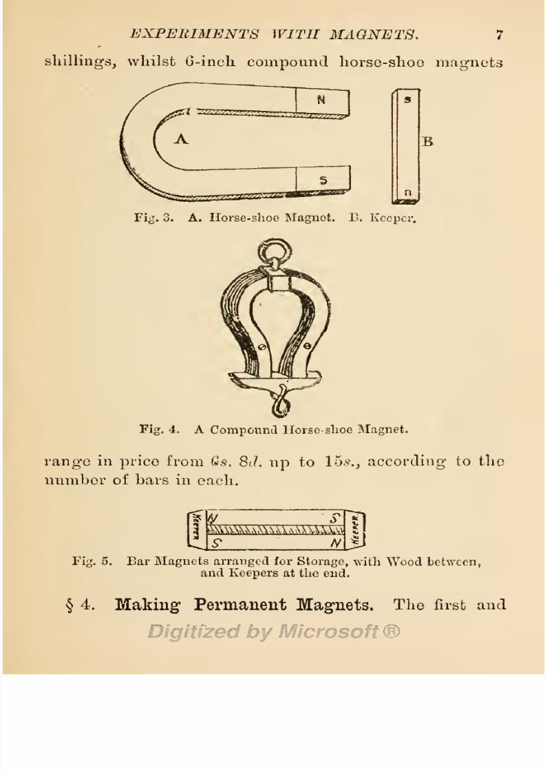
shillings,
whilst
6-inch
compound
horse-shoo
magnets
Fig.
3. A. Horse-shoo
Magnet.
E.
Keeper.
B
Fig.
4.
A
Compound
Horse-
shoe
Magnet.
range
in
price
from
Qs. 8J.
up
to
15s.,
according
to
the
number
of
Lars
in
each.
i^\\\U\,\\U\,vUUS3^
S*
N
Fig.
5.
Bar
Magnets
arranged
for
Storage,
with
Wood
between,
and
Keepers
at
the
end.
§
4.
Making
Permanent
Magnets.
The
first
and

8/20/2019 electrical experiment.pdf
http://slidepdf.com/reader/full/electrical-experimentpdf 26/325
8
ELECTRICAL
EXPERIMENTS.
most
important
experiment
to
be
performed
with, a
per-
manent
magnet,
is,
to
charge
another
bar of
steel
with
magnetism.
It
has
been
shown
in
§
2,
that
a
bar
of
steel
may
be
charged
with
magnetism
by
stroking
it
with
a
natural
lodestone.
This
magnetized
bar
may
be
employed
in
magnetizing
other steel
bars,
and
these
in
turn
may
be
employed
indefinitely
for
the same
purpose,
without
limit as
regards
numbers,
without
weakening
the
charge
in the
originals.
But,
although
the
number
of
magnetized
bars
may
be increased
without
limit
by
stroking
them
in
turn
with
one
permanent
magnet,
there
is
a
limit
to the
strength
of the
magnetic
charge
obtain-
able
from
a
single magnet,
and
this
limit
is
denned
by
the
strength
of the
magnetic
charge
in the
original
inducing
magnet.
Hence
we
cannot
induce
a
higher
charge
of
magnetism
in
a
steel
bar,
than
exists
in the
inducing
magnet
employed
in
stroking
the
bar.
A
weak
magnet
may,
however,
be
made
to
induce
a
higher
charge
of
magnetism
than
its
own
by
the
following
device.
Procure
a
number
of
very
thin
strips
of
hardened
steel,
and
magnetize
them one
by
one with
the
weak
magnet.
This
done,
bind
the
whole
together
to
form
a
compound
magnet,
and
with
this
magnetize
the
larger
bar of
steel,
which can
then be
made
to
receive
a
charge equal
in
strength
to
that of
the
compound
magnet.
Every
bar of
steel varies
in its
capacity
for
receiving a
charge
of
magnetism,
with that
of other
bars
of steel
of
equal
size
and
weight,
this
variation
being
caused
by
the
difference
in
their
quality
and
temper.
The
quality
of
the steel
very
largely
influences
its
capa-

8/20/2019 electrical experiment.pdf
http://slidepdf.com/reader/full/electrical-experimentpdf 27/325
EXPERIMENTS
WITH
MAGNETS.
9
city
for
receiving
a
charge,
but
the
temper
or
hardness
of
the steel influences
its
capacity
still
more.
As
a
rule,
a
soft
mildly-tempered
steel
is
more
readily magnetized
than
a hard
steel,
but the
magnetic
charge
is
not re-
tained
by
the former.
Every
piece
of
steel has its
limit of
capacity,
which is termed
its
saturation
point,
beyond
which it
will
not retain a
magnetic
charge.
We
may
induce
it
to
take
a
higher charge
for
the
moment,
but
the
charge
will
soon
be
dissipated
until
the
point
of
saturation
—
that
is,
its
highest
capacity
—
has
been
reached.
Every piece
of
steel also
manifests
a
reluc-
tance
to
receive
a
charge.
Assuming
that the
magnetic
charge
is
really
an
alteration
in
the
arrangement
of the
molecules
of
iron
and
carbon
in
a
steel
bar,
by
which
they
are
brought
into
a
condition
named
polarization,
then,
it
takes
time,
and a number
of
passes
to
effect
this
alteration.
If the
steel is
soft,
its
molecules
are
more
readily
altered than
those
of a bar
of hard
steel,
the
latter therefore
manifests a
higher
magnetic
reluc-
tance.
On
the
other
hand,
when
the
molecules
have
been
altered
and
brought
into a
state
of
polarization,
they
will
naturally
manifest
a
reluctance
to resume
their
former
condition,
their natural
stiffness
and
un-
yielding
character
favouring
the
retention
of
the
charge.
There
are three
methods
by
which
a
bar
of
steel
may
be
magnetized:
—
1.
Contact
by
single
touch.
2.
Contact
by
double
touch.
3.
Magnetization
by
the
inductive
influence of
electricity.
§
5.
Magnetizing
by
Single
Touch.
Procure
a
bar
of
steel
of
any
size
up
to
6
inches
in
length
by
f-inch

8/20/2019 electrical experiment.pdf
http://slidepdf.com/reader/full/electrical-experimentpdf 28/325
10
ELECTRICAL
EXPERIMENTS.
in
width,
by
j-inck
in
thickness,
and
have
it
made
as
hard
as
fire
and
water
will
harden
it
—
that
is,
let
it
be
heated
to
a
bright
glowing
red
tint and
dipped suddenly
into
very
cold
water.
Place
the
hardened
bar
of
steel
on
a table
or
bench,
and
stroke
it
with
a
permanent
magnet
in
the
following
manner
:
—
Lay
the
north
pole
end
of
the
permanent
magnet
on
the
middle of the
bar
and
draw
the
magnet
slowly
along
to
the
end,
then
lift
the
magnet,
lay
its
end
again
on
the
middle
of
the
bar
and
again
draw it
to
the
end.
This
motion
is
shown
by
the
direction
of
the
arrow
in
Fig.
6.
Repeat
this
Fig.
6.
Magnetizing
Steel
Bar
by
Single
Touch.
some
ten
or
twelve
times.
Then
reverse
the ends of
both
steel
bar
and
magnet,
and
magnetize
the
unmag-
netized
end
in
a
similar
manner
with
the
south
pole
of
the
magnet.
To
make
sure
of
the
poles,
mark
this
last
end
of
the
bar
with
a
file,
this
should
then
be the
north
end
of
the
newly
made
magnet.
This
done,
test
its
strength
on
a
few
iron
nails,
and its
polarity by
its
relation
to
another
magnet,
as shown
in
§
9.
A
horse-
shoe
magnet
maybe
charged
in
a
similar
manner,
taking

8/20/2019 electrical experiment.pdf
http://slidepdf.com/reader/full/electrical-experimentpdf 29/325
EXPERIMENTS
WITH
MAGNETS.
11
care
to have
the north
pole
of
the
inducing magnet
on
the
limb intended
for the
south
pole
of
the
other,
as
shown
at
Fig.
8
;
or
a bar of steel
may
be
magnetized
with
a horse-shoe
magnet,
as shown
in
Fig.
7.
This
Fig.
7.
Magnetizing
Steel
Bar with
Horse-shoe
Magnet.
MS
SW
Fig.
8.
Arrangement
of
Horse-shoe
Magnets
for
Magnetizing
and
Preservation.
method
of
magnetizing,
is
only
suitable
to
small
magnets
below
the
size
given
above,
as it
only produces
a
feeble
magnetic
power.
It
may
be
employed
in
magnetizing
needles,
steel
pens,
and other
light
pieces
of
steel
used
iu
experiments.
If
a
piece
of
unmagnetized
steel
is
bent
in
the
form
of
a
horse-shoe
magnet
and
placed
with
its
two
ends
in contact
with
the
poles
of
a
per-
manent
horse-shoe
magnet
on
a
plane
surface,
it
may
be
strongly
magnetized
in
the
following
manner
:
—
Place
a
keeper
made
of
soft
iron
on
the
bend of
the
unmag-
netized
steel,
across
both
limbs,
and
draw it
along
over
the
limbs
of
this
and the
magnet,
to
the bend
of the
magnet;
then
lift
the
iron,
place
it
again
on
the
bend,

8/20/2019 electrical experiment.pdf
http://slidepdf.com/reader/full/electrical-experimentpdf 30/325
12
ELECTRICAL
EXPERIMENTS.
draw
it
along
as
before,
and
repeat
this
operation
some
twelve
or
fifteen
times.
Turn
over
both
horse-shoes
without
separating
them,
and
repeat the
operation
on
the
other
sides.
By
this
method,
invented
by
Jacobi,
the
steel
may
be
powerfully
magnetized,
it
is
said,
some
fifteen to
twenty per
cent,
higher
than
by
the
single-
touch
method
first described.
§
6.
Magnetizing
by
Double
Touch.
This
method
of
magnetizing
steel,
invented
by
Dr.
Knight
in
1745,
is also named
magnetizing
by separate
touch.
The
bar
to
be
magnetized,
is
laid
on
a
plain
surface
such
as that
of
a
table
or
bench,
and
two
opposite
poles
of
two
equally powerful
magnets
are
placed
on
the
middle
of
the
bar,
as shown
at
Fig.
9.
The
magnets
are
then
Fig.
9.
Magnetizing
Steel
by
Double Touch.
drawn
in
opposite
directions
to the
end
of the
bar,
then
lifted
and
placed
again
in the
centre,
as
shown
by
the
direction
of
the arrows.
This
operation
is
repeated
some
twelve
or
more
times
on
one
face,
then
the
bar
is
turned
over
and
the
operation
is
repeated
on
the other
face
of
the
bar.
This
method
was
improved
by
M.
Duhamel,

8/20/2019 electrical experiment.pdf
http://slidepdf.com/reader/full/electrical-experimentpdf 31/325
EXPERIMENTS WITH
MAGNETS.
13
by
placing
the bar
on the
ends
of
two
fixed
magnets,
as
shown
at
Fig.
10.
Steel
magnetized
by
this method
is
s
h
s
fj
Fig.
10.
Duhamel's
Method of
Magnetizing
Steel
by
Double
Touch.
found
to
be more
permanently magnetic
than
by
any
of
the
other
methods
previously
described.
The bar
to
be
magnetized
forms
a
bridge
across
the two
poles
of
two
permanent
magnets,
and must
be
rubbed
by
another
magnet
with
poles relatively
arranged,
as
shown
in
the
annexed
figure.
It should be
noted
that the
relative
positions
of
the
poles
must
be maintained
as
shown
in
the
figure,
and
the
inducing magnets
be inclined at an
angle
of
from
15°
to
20°
to
produce
best
results.
§
7.
Magnetizing
by
Electric
Induction.
If
we
en-
velop
a bar
of
unmagnetized
hard steel with
a
coil of
insulated
copper
wire,
and
send
a
strong
current
of
electricity
through
the
wire,
the
electric current
will
induce a
magnetic
charge
in
the
steel,
which
will
per-
manently
retain
the
charge
after the
current
has
ceased
to
flow.
By
repeating
this
operation
several
times,
the
steel will
be
charged
up
to
its
full
capacity,
and
may
then
be said
to
be saturated
with
magnetism.
Wire
of

8/20/2019 electrical experiment.pdf
http://slidepdf.com/reader/full/electrical-experimentpdf 32/325
14
ELECTRICAL
EXPERIMENTS.
any
size
may
be
employed
for this
purpose,
and
it
may
be
insulated
with
any
of
the
insulating
substances
in
general
use
for
the
purposes
of
insulation,
but best
results are
obtained when
the
following
conditions
are
fulfilled.
The wire
must
be
large enough
to
carry
an
appreciable
volume of current without
raising
its
tem-
pei'ature
high
enough
to
injure
the insulation.
As
the
strength
of
magnetism
induced
by
such
a
coil
is
pro-
portioned
to the
strength
of
the
electric current
flowing
through
it,
the wire must be cither
large
enough
to
carry
a
strong
current,
or
must
envelop
the
bar
many
times to
multiply
the
effects
of
a weak
current.
The
strength,
of
the
magnetic
charge,
is
proportioned
to
the
volume of
electric current
in
amperes, multiplied by
the
number of
turns
in
the
coil.
Hence,
if
a
current
of
ten
amperes
is
sent
through
one
turn
of
wire
wound
around
a
steel
bar,
and a
current of one
ampere
is sent
through
a
wire
making
10 turns
around
a steel
bar,
the
magnetic
strength
induced
in
both will be the
same. As
the
in-
ductive
influence of increased turns of wire becomes
less
when
they
are
extended
beyond
three
times the
diameter of the core
or
central
opening
of
the
coil,
it
is advisable to have
a thin
insulation so
as
to
have
many
turns
of
wire
lying
close
to
the
bar
to
be
magnetized.
As No.
20
B.W.G.
copper
wire
will
carry
safely
1
ampere
of
current,
and
No.
18
will
carry
1'8
amperes
of
current,
these
sizes
are
to
be
recommended
for
magne-
tizing
coils.
Silk
soaked
in
melted
paraffin
is
the
best
insulator,
but
cotton
insulation
costs
less
than
silk,
and
may
be
employed
where
the
least
cost
is a
consideration.

8/20/2019 electrical experiment.pdf
http://slidepdf.com/reader/full/electrical-experimentpdf 33/325
EXPERIMENTS
WIT
II
MAGNETS.
15
Although
a
magnet
may
be
made
by winding
a
quan-
tity
of
insulated
copper
wire around
a
bar
of
steel,
and
sending
an
electric
current
through
the
coil,
it is
found
more
convenient, when
making
several
magnets,
to
have a
portable
coil,
in
Avhich
the
steel can be
placed,
magnetized,
and
withdrawn
at
will. To make
such
a
coil,
procure
a
strong
reel
or
bobbin of
wood
having
a
body
or
core of a
sufficient
diameter to
exceed
the
full
size
of
the
bars
intended
to
be
magnetized.
Divide this
reel into
two
equal parts by sawing
the
body
in
two
obliquely,
as
shown
at
Fig.
11,
then stick
the
two
parts
n
u
Fig.
11.
Split
Bobbin
for Coil
of
Wire.
together
temporarily
with
pitch
or
shoemaker's
wax,
and fill
the
reel
with
No.
20 silk-covered
wire
wound
on
regularly
in
coils side
by
side.
Before
winding
on
the
wire,
however,
lay
on two or
four
pieces
of
strong
tape
lengthwise
along
the
body
of the
reel,
and when
the
reel is
full,
tie
these
pieces
of
tape
firmly
to
the coil.
This
will
keep
the coils of
wire
in
form,
after
the two
halves of the
reel
have
been
removed,
and
preserve
the
wire
in
the form
of an
open
hank,
as
shown
at
Fig.
12.
The
hank
should
then
be
steeped
in
hot
melted
paraffin,
and laid
aside
to cool.
The
coil of
wire
mav
be con-
solidated
with
an
alcoholic
solution
of
shellac
applied

8/20/2019 electrical experiment.pdf
http://slidepdf.com/reader/full/electrical-experimentpdf 34/325
16
ELECTRICAL
EXPERIMENTS.
to each
layer
whilst
winding
on
the
wire,
or
with
a
solution
of
gum
copal
in
ether,
similarly
applied
; or,
if
cheapness
be
desired,
the reel
or
mandrel
may
be en-
veloped
in
paper
to
prevent
the
wire
sticking
to
it,
and
the
layers
of
wire
may
be basted with
hot
glue.
As
a
Fig.
12.
Wire
Coil
for
Magnetizing
Steel.
finish,
the
whole coil
may
be
painted
with
sealing-wax
varnish.
To
use
this
coil
for
the
purpose
of
making permanent
magnets,
its
two
free ends
must be connected
to a
powerful battery,
such as two
or three
cells
of
a
Grove
or
Bunsen
battery
arranged
in
series,
or connected
with
some
other
generator
of
electricity
having equal power.
The
bar
to
be
magnetized
is
then
placed
in
the
coil,
and
moved
backwards and forwards several times
through
the coil from
end to end of
the
bar,
at
the
same
time
rapping
it
smartly
with
a
rod of iron
or
any
other metal.
The
vibration
of
the
bar under
these
rappings
tends to
hasten
magnetic
saturation,
and
secure
a
higher
mag-
netic
intensity.
Frequent
interruption
of
the
current
flowing
through
the
coil has a similar
effect,
but
the
interruptions
should
take
place
when the
bar is
halfway
into
the
coil,
or,
in
other
words,
when
the
coil is near

8/20/2019 electrical experiment.pdf
http://slidepdf.com/reader/full/electrical-experimentpdf 35/325
EXPERIMENTS WITH
MAGNETS.
17
the middle
of
the
bar,
and this
should
be its
position
when the
magnetizing
process
is
finished.
An
electro-magnet
may
be
employed
in
magnetizing
steel
bars,
the
process
being
the
same
as
that
of
single
or
double touch
with
permanent
magnets.
Contact
with
the
poles
of a
dynamo-electric
machine
will
also
permanently magnetize
steel,
and
even
close
proximity
to such
a
highly
magnetized
field
will
induce a
mag-
netic
charge
in
steel,
—
as
the
wearers
of
watches
too
often
find
to their
cost.
§
8.
Lines of
Magnetic
Force.
Although
a
bar
of
steel
charged
with
magnetism,
has
the
charge
equally
distributed
through
every particle,
or,
in
other
words,
is
quite permeated
with
the
charge,
its
manifestation
is
chiefly
confined to
the
two
ends.
These
are
known
as the
two
poles,
and
towards
these the
lines of
mag-
netic
force
are
determined.
This
may
be
shown
by
placing
a
magnet
under a
sheet
of
smooth
paper,
or
under
a sheet
of
glass,
and
sprinkling
some
iron
filings
over
its
surface. On
lightly
tapping
the
paper
or
the
glass
with
a
quill
or a
straw,
so as to
slightly
shake
it
and
give
movement to
the iron
filings,
these will
be
arranged
by
the
lines of
magnetic
force
as
shown
at
Fig.
13. If
the
paper
be held
over
the
poles
of
a
horse-shoe
magnet,
the
filings
will
be
arranged
as
shown
at
Figs.
14
and
15.
A
close
analogy
is
shown
between
the
lines
of
a
magnetic
charge
and
that
of
a
static
charge
of
electricity,
in
the
tendency
to run
towards
the terminal
ends and
leak off
there,
and
also
to
induce
an
opposite
charged
condition
named
polarity
at
those
c

8/20/2019 electrical experiment.pdf
http://slidepdf.com/reader/full/electrical-experimentpdf 36/325
IS
ELECTRICAL
EXPERIMENTS.
terminals. This
latter
condition
will
be
noted later
on.
The
detrimental
consequences
of
leakage
from a
magnet
may
be
prevented
by
placing
a
piece
of soft iron to
each
pole,
or,
in
the case
of
a
horse-shoe
magnet,
a
piece
of
soft iron aci'oss
the
poles
will suffice.
This
piece
of
iron is
named
the
keeper,
because
it
keeps
the
magnetic
^^ft^>
I,
Fig.
14.
Fig.
13.
Lines
of
Magnetic
Force—
Bar
Magnet.
Lines of
Magnetic
Force—
Horse-shoe
Magnet.
charge
from
leaking
off.
The
experiment
with
iron
filings
should
be varied
by
using
a
bar
magnet,
a
horse-shoe
magnet,
and
two
bar
magnets
pai^allel
to
each
other
with
their
opposite
poles
side
by
side,
and
also
with
like
and
unlike
poles
end
to
end,
as
shown
at
Fig.
16. The
experiment
should also be
tried
with,
and
without
keepers
to the
magnets.
If
we
wish
to
preserve

8/20/2019 electrical experiment.pdf
http://slidepdf.com/reader/full/electrical-experimentpdf 37/325
EXPERIMENTS WITH
MAGNETS.
19
Fig.
15.
Lines
of
Magnetic
Force
over
the
Poles
of
the
Horse-shoe
Magnet.
ATTRACTION.
U8BH
8EPUL5I0N.
Fig.
16.
Lines
of
Magnetic
Force
around
like
and
unlike
Poles
of
Magnets.

8/20/2019 electrical experiment.pdf
http://slidepdf.com/reader/full/electrical-experimentpdf 38/325
20
ELECTRICAL
EXPERIMENTS.
the
arrangement
of
filings,
the
glass
should
have
a
thin
coat
of
wax or of
varnish.
That
the
magnetic
charge
permeates
the
whole
of
the steel
bar,
may
be
proved
by magnetizing
a
thin
piece
of
very
brittle
steel,
such as
a
hard-tempered
piece
of crinoline steel
or
a
knitting
needle,
then
breaking
this
into small
pieces.
Each
piece
will
be
found to be
equally
magnetized,
and
each
will
have
polar
extremities,
as
in
the
whole
magnet.
This
is
shown
at
Fig.
17.
These
fragments
may
be
used
in
further
experiments
to
demonstrate
the
effects
of
heat
-f
g
njsesssss
N
teassBS*
ur^-ns
wn
—
g
—
,js
Fig.
17.
Effects
of
Breaking
a
Magnet.
on
magnets.
As
the
temperature
is
raised,
the
mag-
netic
charge
will
be
dissipated,
until,
when
at
a
red
heat,
no
evidence
of
a
charge
is
perceivable,
and the
piece
of
steel
will
be
found
to
have lost
it
altogether.
A simi-
lar
effect
will
follow
from
repeatedly
jarring
a
magnet.
§
9.
Magnetic
Repulsion.
Although
the
natural
attribute
of
a
magnet
is to
attract,
it
also
possesses
the
power
of
repulsion.
It
has
been
shown
in
the
preceding
section,
that
a
magnet
is
capable
of
attracting
iron
at
both
of
its
poles,
as
the
iron
filings
cluster
around
both
in
equal
quantity.
Its
behaviour
to other
8/20/2019 electrical experiment.pdf
http://slidepdf.com/reader/full/electrical-experimentpdf 39/325
EXPERIMENTS
WITH
MAGNETS.
21
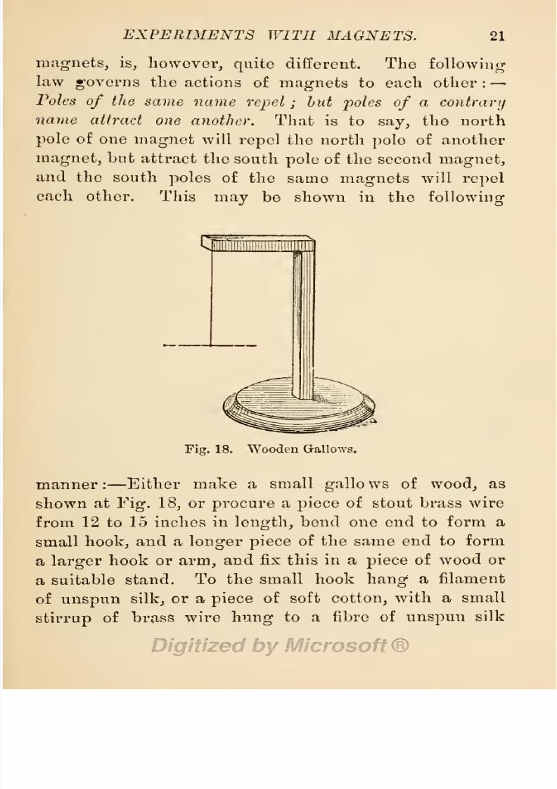
mag-nets,
is,
however,
quite
different.
The
following
law
governs
the
actions
of
magnets
to
each
other
:
—
Poles
of
the
same
name
repel;
but
poles
of
a
contrary
name
attract
one
another.
That is
to
say,
the
north
pole
of
one
magnet
will
repel
the north
pole
of
another
magnet,
but
attract
the south
pole
of the second
magnet,
and
the south
poles
of
the
samo
magnets
will
repel
each
other.
This
may
be shown
in
the
following
Fig.
18. Wooden Gallows.
manner:
—
Either
make
a small
gallows
of
wood,
as
shown
at
Fig.
18,
or
procure
a
piece
of
stout
brass
wire
from
12
to
15
inches
in
length,
bend one end
to
form
a
small
hook,
and a
longer piece
of the same
end
to
form
a
larger
hook
or
arm,
and fix
this
in
a
piece
of
wood
or
a
suitable
stand.
To the
small hook
hang
a
filament
of
unspun
silk,
or a
piece
of soft
cotton,
with
a
small
stirrup
of
brass
wire
hung
to
a
fibre
of
unspun
silk

8/20/2019 electrical experiment.pdf
http://slidepdf.com/reader/full/electrical-experimentpdf 40/325
22
ELECTRICAL
EXPERIMENTS.
attached
to
the
lower
end.
A
magnetized
needle or
a
magnetized
steel
pen
must
be
nicely
balanced
in
this
stirrup. If
a
filament
of
unspun
or
cocoon
silk
is
employed,
the
needle
will
take
np
a
position
when
at
rest,
pointing
due north
and
south.
If
we
bring
the
north
pole
of
another small
magnet
near
the north
pole
of
the
suspended
magnet,
it
will
swing
away
as
if
repelled
by
a breath
of
air.
If,
however,
we
bring
the
Fig.
19.
Stirrup
to
hold
Magnets,
Tubes, etc.,
in Electrical
Experiments.
north
pole
of the
magnet
in
near
proximity
to
the
south
pole
of
the
suspended
magnet,
it
will
be
attracted.
If
a
lai-ge
magnet
is
employed,
the
action
will
be
strong,
and
may
spoil
the
experiment
by
attracting
the
sus-
pended
magnet
instead of
repelling
the
opposite
pole,
and
may
also
reverse
the
poles
of
the smaller
magnet.
It will
be advisable
to
substitute
an
iron
nail
or
a
piece
of
iron
wire
for
the
magnets,
and
note
the
difference.
Both
ends
of the
iron wire
will
be
attracted
equally
to

8/20/2019 electrical experiment.pdf
http://slidepdf.com/reader/full/electrical-experimentpdf 41/325
EXPERIMENTS WITH MAGNETS.
23
either
polo
of tlio
magnet.
If
the
iron
wire
is sus-
pended
in
the
stirrup,
it
will
bo
attracted
to
the
magnet;
but
if
the
magnet
is
in the
stirrup,
it will
appear
to
be
attracted
to the
iron.
This
will
illustrate
the
influences
of
masses of
iron
such
as that of
an
iron
ship
on
the
movements
of
the
mariner's
compass.
If two bits
of
iron
wire
are
suspended
by
two
threads
from the
hook,
they
will
mutually
repel
each
other
when a
magnet
is
brought
near
them.
Magnetic
re-
pulsion
may
also
be illustrated
by hanging
a
piece
of
iron,
such
as
a
key
or
nail,
to one
magnet,
and
then
sliding
the
opposite pole
of
another
magnet along
over
the
first.
When
the
pole
of
the
second
magnet
is near
enough
to the
suspended
article,
it will
drop
as
if
the
magnetism
of
the first bar had
been
lost,
but
this is not
so,
the
apparent
loss
being
due to mutual
repulsion.
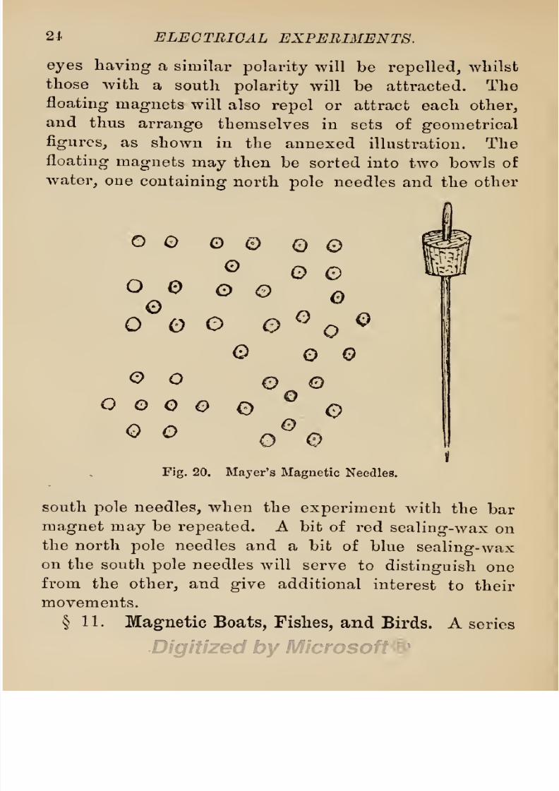
§
10.
Mayer's
Magnetic Floating
Needles.
This
beautiful
experiment
(devised
by
Prof.
A.
M.
Mayer,
of
the
Stevens
Institute,
New
Jersey),
illustrates both
magnetic
repulsion
and
the
reciprocal
action
of
magnets.
Procure
a
number of
stout
sewing
needles,
and
an
equal
number
of
small
corks,
|-inch
in
diameter
by
-g-inch
in
length.
Magnetize
all the
needles,
some with
their
eyes
and
some
with
their
points
north
poles,
and
stick
each
in
a
piece
of
cork,
with
the
eye
of
each needle
just
showing
above
each
piece
of
cork,
as
shown
at
Fig.
20.
Throw them
all into
a
large
bowl
of
water,
and note
their behaviour.
Next
get
a
bar
magnet
and
pass
one
of
its
poles
slowly
over the
floating
magnets.
If
the
north
pole
of
the
magnet
is
presented
to
them,
all those
with
8/20/2019 electrical experiment.pdf
http://slidepdf.com/reader/full/electrical-experimentpdf 42/325
21
ELECTRICAL
EXPERIMENTS.
eyes
having
a
similar
polarity
will
be
repelled,
whilst
those
with
a
south
polarity
will
be
attracted.
The
floating-
magnets
will
also
repel
or
attract each
other,
and
thus
arrange
themselves
in
sets
of
geometrical
figures,
as
shown
in
the
annexed
illustration.
The
floating
magnets
may
then be
sorted
into two bowls
of
water,
one
containing
north
pole
needles
and
the
other
©
°
o
e
O
Q
e
6
o
o
o
o
°
°
OG
O
O
O
O
°
°
0%
Fig.
20.
Mayer's
Magnetic
Needles.
south
pole
needles,
when
the
experiment
with
the bar
magnet
may
be
repeated.
A bit
of
red
sealing-wax
on
the north
pole
needles
and
a
bit
of
blue
sealing-wax
on
the
south
pole
needles will
serve
to
distinguish
one
from
the
other,
and
give
additional
interest
to
their
movements.
§
11.
Magnetic Boats,
Fishes,
and
Birds.
A
series

8/20/2019 electrical experiment.pdf
http://slidepdf.com/reader/full/electrical-experimentpdf 43/325
EXPERIMENTS
WITH
MAGNETS.
25
of
very pretty
parlour
experiments
may
be
performed
with
a
moderately
strong
horse-shoe
permanent
magnet
and
a few
pieces
of iron
wire
properly
arranged
in
ways
now
to
be
described.
1.
With
a
sharp
pocket-knife
as
a
tool,
carve
out
of
cork,
willow,
alder,
sycamore,
or
similar
light
wood,
a
fleet
of
tiny
model
boats,
from
J
to
1 inch
in
length.
Insert
in
each
boat
a keel
of
iron
wire,
and
bring
one end
of
the wire
over
the
bow
to
form
a cut-water.
Paint
each
little
boat or
ship
as
fancy
may
direct,
allow
the
paint
to
dry,
then
float
the
little
fleet
on
a bowl of
water.
This
fleet
will
follow
a
magnet
held
over
it
or
near
it,
and,
if
a
bar
magnet
is
held
in a stick
fashioned
as
a
magician's
wand,
the
movements
of
the
whole fleet
may
be
controlled
by
waving
the
wand over
it
or
pointing
to
any
part
of it.
If
some
larger
models,
shaped
as
ships
and
fitted
with
magnetized
pieces
of
steel,
be introduced
into
the
fleet,
a
still
further
variety
of
movements
may
be
effected,
as
the
magnetic
ships
attract the boats
or
repel
each
other.
2.
Models
of
swans,
ducks,
geese,
and
other
aquatic
fowl
may
also
be made
in
wax,
or
carved
out
of
wood,
each
being
furnished with
a small
magnet,
or with a
piece
of
iron
wire,
or
an iron
brad.
These
flocks
of
aquatic
models
may
be
induced
to follow
a
piece
of
bread
or a
biscuit
in which
a
magnet
has
been
con-
cealed,
whilst
those
furnished
with
small
magnets
may
be
made to
scatter
and
scurry
away
by
pointing
a
magnetized
steel
gun
at
them,
providing
the
barrel of
the
gun
be
pointed
near
a like
pole
of
the
magnet
concealed
in the
bird.
3.
Another
variation
of
the even-

8/20/2019 electrical experiment.pdf
http://slidepdf.com/reader/full/electrical-experimentpdf 44/325
26
ELECTRICAL EXPERIMENTS.
ing's
amusement
may
be
provided by
constructing-
a
few
small
fish
out
of
very
thin
tinned
iron,
such
as
that
used
in
making
condensed
milk
tins,
and
throwing
these in
the
bowl
of
water.
If the
small
pieces
of
tin
are
cut out
with
scissors
or
shears
in
the form of two
halves
of a
fish,
then
bevelled,
and the
two halves
care-
fully
soldered
together
so
as to
make
the fish hollow
and
water-tight,
it
will
float,
whilst
others
may
be
made
not so
buoyant,
and
others
to
lie*
on
the
bottom
of
the
bowl.
The
models should be
lacquered
with
suitable
coloured
lacquers,
and,
if
they
can
be
made
of
stamped
pieces
of
tin
to more
nearly
resemble
fish,
so
much
the
better.
These fish
may
be
caught
with
a
mag-
netized
hook,
or
be made to
follow artificial bait con-
cealing
a
magnet.
4.
A
pleasant
variation
of
the
same
experiment
may
be
performed
with
stuffed
birds,
or
models of the same. Birds
made of
various
tinted
plush
and
feathers,
attached
to
frameworks
of
iron
wire,
and
mounted
on
oscillating
perches
in
various
parts
of the
room,
or
suspended
with
outstretched
wings
from
pendants
or
brackets,
may
be
animated
with a
magnetic
wand
and
induced to
peck
at
biscuits
concealing magnets.
If
ordinary
stuffed
birds
are to
be
utilised
in
this
experiment,
a
small
piece
of
iron
should be
concealed
in
each head or
beak,
and
each
bird
so
poised
as
to fall
back
in
a
position
of
rest
when
the
magnet
has
been
withdrawn.
This
may
be done
by
placing
a small
piece
of
lead
under
the tail
of
each
bird.
Insects
such
as
bees,
butterflies,
and
dragon-
flies,
may
be
made
of
plush
and
rice-paper
artistically

8/20/2019 electrical experiment.pdf
http://slidepdf.com/reader/full/electrical-experimentpdf 45/325
EXPERIMENTS
WITH
MAGNETS.
27
painted,
and
suspended by
cocoon
silk
from stalks of
ferns or
flowers,
and these
may
be
agitated by
passing
the
magnetic
wand over
them,
if
each insect
contains
a
piece
of
iron
wire,
or
has a
framework
of this wire.
With a
strong
short bar
magnet
concealed beneath
the
fore-finger
of the
right
hand,
a
semblance of
magic
may
be
imported
into
the
entertainment.
Magic
Wand.
To
construct
a
magic
wand
for
use
in
these
experiments,
get
an
ebony
ruler or
one of ebonized
wood
(any
other
wood,
or
ivory,
will
serve
the
purpose),
bore
a
hole
through
it,
or
bore
a
hole
in
each
end,
and
either
insert
a
long
thin
rod of
magnetized
steel,
or
two
short
bar
magnets,
one
in
each
end,
with
a
south
pole
at one
end
and
a north
pole
at
the
other.
These
may
be
so
arranged
as to
be
removable
at
will,
if
desired,
by
unscrewing
the
capped
end
of the
ruler.
Otherwise,
the ends of the
magnets
may
be
disguised
with
black
enamel
or black
sealing-wax.
The wand
may
have
ornamental
ends,
and
be
carved or
turned,
or orna-
mented as taste
may
direct.
§
12.
Magnetic
Suspension.
To
some
persons
im-
perfectly
acquainted
with
magnets,
it
may
seem
pos-
sible
to so
arrange
a
magnet
and
a
piece
of
iron and
steel
as
to
keep
the
latter
suspended
in
the
air,
at
a
fixed
distance
from
the
magnet.
As, however,
one
of
the
laws
of
magnetism,
discovered
by
Coulomb,
is
that
magnetic
attractions
and
repulsions
vary
inversely
in
strength
as
the
squares
of
the
distances
from
their
poles,
it
follows that
any
attractive material
brought
within
the
attractive influence of
the
magnet
must
be
drawn
to

8/20/2019 electrical experiment.pdf
http://slidepdf.com/reader/full/electrical-experimentpdf 46/325
28
ELECTRICAL
EXPERIMENTS.
it,
since
when once
within
the
sphere
of
attraction
the
strength
of this
rapidly
increases.
Magnetic suspen-
sion
in
mid-air
can
only
be
effected
by
holding
the
attracted
object
back
from
actual
contact
with
the
magnet by
means
of
a
filament
of
silk
or
similar
fibre,
or
by
nicely
balancing
the iron
or
steel
between
the
attractions
of two
magnets.
Magnetic
repulsion
may
be
illustrated
by
means
of
an
experiment
with
a
magnetized
needle
held
over
a
magnet
by
a
thread
of
cocoon
silk.
If the
point
of
the
needle
is
given
a
north
polarity
and
held over
the
north
pole
of
a
strong
magnet,
the needle
will
be
repelled
upward
and
appear
to
be
floating
in the air
over the
magnet.
This
ex-
periment
has
been
named
Mahomet's
coffin/'
to
com-
memorate
the
erroneous
notion,
once
entertained,
of
Mahomet's
body
being
placed
in
a
steel coffin and
sus-
pended
in
the
air
between
two
magnets
in
a
mosque
at
Medina.
By
attaching
a
thread
of
silk
by
means
of
wax
to
the
underside
of
an
iron
bar
and
holding
a
strong
magnet
over
it,
the
iron
may
be
made
to
appear
as
if
suspended
in
air
by
magnetic
attraction.
Another
interesting
experiment,
illustrative of
mag-
netic
suspension,
may
be
performed
with
a
pendulum
furnished
with
an iron
top
nicely
rounded on
its
upper
end.
This
rounded
part
must be
placed
in
contact
with
a
strong
bar
magnet,
from
which
the
pendulum
may
be
suspended
by
magnetic
attraction,
and
can then
be
swung
to
and
fro
or
made
to
describe
a
circle
without
loosening
its
hold,
providing
the
weight
is
proportioned
to
the
strength
of
the
magnet.

8/20/2019 electrical experiment.pdf
http://slidepdf.com/reader/full/electrical-experimentpdf 47/325
EXPERIMENTS
WITH
MAGNETS.
29
When
iron
is
in
contact
with
a
permanent
magnet,
its
strength
or
power
of
holding
up
a
weight
is
increased.
This is named the
portative
force
of
a
magnet.
It
may-
be tested
by attaching
a
scale-pan
to
the
iron
keeper,
and
adding
weights
or lead
shot
until
the
keeper
parts
from
the
magnet.
The
magnet
must
be
suspended
vertically,
and the
scale-pan
must
be
hung
from
a
point
exactly
in the
ceutre
of
the
magnet
or
midway
between
the
two
poles. Magnets
have
been
made
to
sustain
ten
or
twelve
times their
own
weight,
and
Jamin
con-
structed
compound
magnets
of thin
steel
plates
which
sustained
fifteen
times
their
own
weight.
These com-
pound
magnets
were
constructed
with
five or sis
thin
horse-shoe
magnets
bound
together
with
a
brass
band,
this
arrangement
making
a
stronger
magnet
than
a
solid bar of steel
the
same
thickness. He
found,
how-
ever,
that
the
strength
of
these
magnetic
batteries was
not
proportioned
to
the number
of thin
magnets
thus
bound
together.
For
instance,
taking
a
thin
magnet
capable
of
holding
up
a
three-pound
weight,
—
by
bind-
ing
six such
magnets
together
he
could not
get
the
compound
magnet
to
hold
up
six
times
three
pounds,
but
only
fifteen
pounds,
the
power
to hold
the
remain-
ing
three
pounds
being
lost in
the
repellent
action
of
one
magnet
on
another.
The
strongest
compound
mag-
nets are
those
which
are made
of
five
or
seven
thin
horse-shoe
magnets
of
unequal
length,
bound
together
with
one
long
magnet
in
the
centre,
the
next
two
on
each
side
being
£-inch
shorter,
the next shorter
still,
and
so
on.
By
this
arrangement
the
repellent

8/20/2019 electrical experiment.pdf
http://slidepdf.com/reader/full/electrical-experimentpdf 48/325
30
ELECTRICAL
EXPERIMENTS.
action of like
contiguous poles
on each
other
is
much
reduced.
§
13.
Magnetic
Induction.
That
a
magnet
has the
property
of
inducing
magnetism
in
a
piece
of
steel,
has
been
clearly
shown
in
§ §
2
to
6.
It
also
has
the
property
of
inducing
a
magnetic charge
in
a
piece
of
iron,
and
converting
this
into a
magnet
whilst
within
the
sphere
of
magnetic
influence.
An
interesting
experiment
illustrating
this
property,
may
be
performed
with a
number
of thin
iron
bars,
such
as
strips
of
hoop-
iron,
and
a
moderately
strong
horse-shoe
magnet.
Sus-
pend
the
magnet
with
its
poles
in
a
vertical
position,
and
attach
one
end
of
the
first
strip
to
one
pole
of
the
magnet.
It
will be
seen
that
the
iron
has
become
a
magnet
by
induction,
for
it
will
attract
another
strip
of
iron held
to
its
lower
end.
Add
another
strip
of
iron,
this
also
will
be
attracted
to
the
first
strip by
magnetic
induction.
Add
strip
to
strip
in
a
similar
manner,
as
long
as that
pole
of the
magnet
will
bear
the
weight,
then add
similar
strips
to
the
other
pole.
It
will
be
found
that
a
magnet
can
hold
up
a
greater
weight
of
such
strips
arranged
in
this
way
than it can
of
similar
strips
placed
across
the
poles,
because
each
strip
induces
magnetism
in
its
neighbour,
thus
affording
mutual
support,
and
the
magnetic
influence
is
extended
to
a
greater
distance
from
the
poles.
If
long
intervals of
time
are
allowed
to
intervene
between
each
addition
of
weight
in
both
cases,
the
portative strength
of
the
magnet
itself
will be
increased.
The
experiment
may
be
varied
by
adding
i-inch
lengths
of
|-inch
iron
rod
to
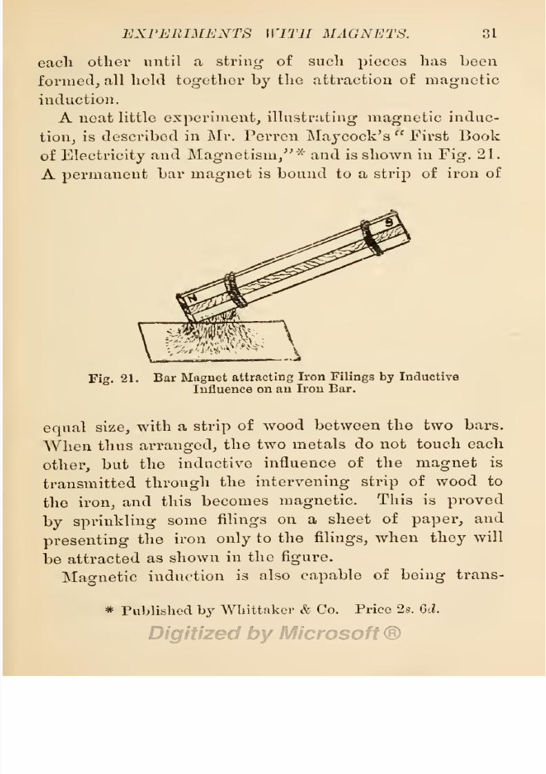
8/20/2019 electrical experiment.pdf
http://slidepdf.com/reader/full/electrical-experimentpdf 49/325
EXPERIMENTS
WITH
MAGNETS.
31
each
other
until
a
string
of
such
pieces
has
been
formed,
all held
together
by
the
attraction
of
magnetic
induction.
A
neat
little
experiment,
illustrating
magnetic
induc-
tion,
is
described
in
Mr.
Perren
Haycock's
First Book
of
Electricity
and
Magnetism,
x
and is shown
in
Fig.
21.
A
permanent
bar
magnet
is bound to
a
strip
of
iron
of
\]
SSfe
\
Fig.
21.
Bar
Magnet
attracting
Iron
Filings by
Inductive
Influence
on
an
Iron
Bar.
equal
size,
with
a
strip
of
wood
between the two
bars.
When
thus
arranged,
the
two
metals
do
not
touch each
other,
but
the
inductive
influence of the
magnet
is
transmitted
through
the
intervening
strip
of
wood
to
the
iron,
and
this
becomes
magnetic.
This is
proved
by
sprinkling
some
filings
on a
sheet
of
paper,
and
presenting
the
iron
only
to the
filings,
when
they
will
be
attracted
as
shown
in
the
figure.
Magnetic
induction
is
also
capable
of
being
trans-
*
Published
by
Whittaker
&
Co.
Price
2s.
6d.

8/20/2019 electrical experiment.pdf
http://slidepdf.com/reader/full/electrical-experimentpdf 50/325
32
ELECTRICAL
EXPERIMENTS.
mitted
to
a
long
distance
through
wires.
This
is shown
in the
magneto
call
bells,
employed
in
telegraph
and
telephone
systems,
and
the
magneto
machines
used
in
working
the
ABC
telegraph
instruments.
Its
action
on a
small scale
may
be
demonstrated
by
a
simple
experiment
made
with a
bar
magnet
and
the
mag-
netizing
coil described
in
§
7. Connect
the
two
ends
of
the coil
to
a
d#licate
galvanometer,
and
plunge
the
magnet
in
the coil.
At
the instant
of
doing
this,
the
needle
of
the
galvanometer
will
be
deflected,
and it
will
be
again
deflected
when
the
magnet
is
removed
from
the
coil,
thus
showing
that the
magnetic
impulses
are
taken
up
by
the
coil
of
wire,
and the
charge
is
trans-
mitted to
the
coil
of
the
galvanometer,
where it
induces
a
magnetic
action
on
the
needle.
In the machines
for
ringing
magneto
call
bells,
and
for
working
ABC
telegraphs,
permanent
magnets
are
swiftly
revolved
near
coils of
wire,
and the
rapid
succession
of
magnetic
impulses
are
transmitted
from
these coils
to similar coils
wound
over
iron
cores
in
the
distant instruments.
This
inductive
action
of
permanent
magnets,
estab-
lishes the relation
of
magnetism
to
electricity,
the
action
of
both
being
reciprocal
;
for,
as
a
current
of
electricity
passing
through
a coil of
wire
wound
over a
steel bar
induces
a
magnetic
charge
in
the
bar, so,
a
magnet
moving
in
a
coil
of wire
sets
up
a
current
of
electricity
in
the
wire.
§
14.
Miscellaneous
Magnetic
Experiments.
Give
a
boy
a
horse-shoe
magnet
and
a
miscellaneous
col-
lection of
metal
scraps,
together
with clear
instructions

8/20/2019 electrical experiment.pdf
http://slidepdf.com/reader/full/electrical-experimentpdf 51/325
EXPERIMENTS
WITH
MAGNETS.
33
in
the
use
of
the
magnet,
and
he
will
amuse
himself
by
the
hour.
The
following
may
he
suggested
among
many
others as most
likely
to
engage
his
attention.
Assorting
Metal.
Put into
a
box,
or a
tray,
a
number
of
brass
buttons,
white metal
buttons,
and iron
buttons,
all
lacquered
or
japanned
to
disguise
them.
Also,
some
iron,
brass,
copper,
and other metal
brads, tacks,
and
nails,
japanned,
lacquered, painted,
or
tinned,
to
give
them
a
uniform
appearance.
These
should
be
assorted
by
the aid
of
a
magnet.
The
magnet
will
pick
out all
the
iron
buttons,
brads,
and
nails.
Common
tinned
iron
pins
may
be
thus detected
when
mixed with
tinned brass
pins.
Jack Straws
. Get
some
iron
wire of
about
No.
1G
gauge,
cut
it
into
various
lengths
of
from 3
to
inches,
and
paint
the
pieces
in
various
colours
and
tints,
or
furnish
each
with
a head of coloured
glass
or
wood. Give
to
each
a
number
or
value,
mix
them
altogether
in a
tray
or
box,
and
proceed
to
pick
them
out as
in
the
game
of Jack
Straws,
using
a
magnet
for
the
purpose.
A
few
blanks
of
brass or
of
copper
wire
introduced
among
the
iron
wires
will
servo
to
increase
the
interest of
the
game.
The
game
may
be
varied
by
placing
a
number
of iron
wires
of
various
lengths
in an
envelope,
with
their
ends
only protrud-
ing,
and
drawing
them one
by
one from
the
envelope
with
the
magnet,
as
in
u
drawing
lots.
Wire
nails
of
various
lengths
may
be
substituted
for
lengths
of iron
wire.
Magnetic
Screens.
A
magnet
will
exert
its
influence
D

8/20/2019 electrical experiment.pdf
http://slidepdf.com/reader/full/electrical-experimentpdf 52/325
34
ELECTRICAL EXPERIMENTS.
on iron
and
steel
through nearly
all
known
substances
except
iron itself.
Get a
compass,
or the small
galvanometer
described
by
Mr. Bottone
in
Electrical
Instrument
Making
for
Amateurs/'
and sold
for
2s.
6cl.
Place
this
on
a
table,
on a
mantelpiece,
on
a
mat or
rug,
on
a slab of
glass,
slate,
marble,
porcelain,
or
similar
stony
substance,
or
over
any
other
metal
except
iron,
then
place
a
strong
magnet
under the
substance
interposing
between
it
and
the
compass.
If
the
sub-
stance
be not
too
thick,
the
needle
of the
compass
will
be
influenced
by
the
magnet
in
a
most
interesting
manner. A
piece
of
sheet
iron
will screen the com-
pass
from
magnetic
influence
and
alter its
behaviour
altogether.
§
15.
Uses
of
Permanent
Magnets.
Permanent
magnets
have
been
and are
employed
in
the
construction
of
magneto-electric
machines,
as
indicated
in the
last
section,
and described
by
Mr. Bottone on
pp.
15
and
175
of his
book
Electric
Bells,
and
All About
Them,
and
also
in
Mr. Poole's
Practical
Telephone
Handbook,
pp.
94-102.
They
are
also
employed
in
the construction
of
magneto-electric
shocking
machines,
as
described
by
Mr.
Bottone
in his
book
Electric
Instrument
Making/'
pp.
90-99.
The
telephone
owes its
origin
to a dis-
covery
of
the
effects
of
magnetic
induction
on
a
diaphragm
of
thin
iron. Permanent
bar
magnets
are
employed
in
the
construction
of Bell
telephone
re-
ceivers,
whilst
horse-shoe
permanent
magnets
are used
in
the
Gower,
Ader,
Siemens,
and
some other
telephone
receivers.
The
single-needle
telegraph
instrument,

8/20/2019 electrical experiment.pdf
http://slidepdf.com/reader/full/electrical-experimentpdf 53/325
EXPERIMENTS WITII
MAGNETS.
35
which has
rendered such
good
service
to
all
the
world
as
a
means
of
intercommunication
between
the
nations,
depends
upon
the
action of
a
small
magnet
for
its
efficiency.
This
action
may
be
thus
explained.
Where
a
small
magnetized
bar
of
steel
is
suspended
or
pivoted
in
a
vertical
position
in a
coil
of
fine
wire,
and
a
current
of
electricity
is
sent
through
the
coil,
its
hollow
core is
magnetized,
and
the
magnetized
air
space
be-
haves
toward
the
magnetized
needle
much
the
same
as
a
permanent
magnet,
repelling
like
poles
and
attracting
unlike
poles
of
the
magnetized
steel.
The
magnetized
steel,
being
free
to
move
in
this
space,
is
attracted
or
repelled
according
to
the
polarity
of
the air
space,
this
being
controlled
by
the
direction
of
the
electric
current
passing
through
the
coil. When
the
current
is
made
to
flow
from
left to
right
in
the
coil,
its
air
core
has a
north
polarity
at
the
right-hand
end
and
a south
polar-
ity
at
the other
end. As
a
consequence,
the
north
pole
of
the vertical
steel
magnet
is
repelled
from
the
right-
hand
end of
the
coil,
and
the
south
pole
is
attracted
to
that
end.
By
reversing
the
direction of
the
current,
the
polarity
of
the coil
is
reversed,
and
the
magnetized
needle made
to
swing
in
the
opposite
direction.
The
electric
current
detectors
employed by
telegraph
lines-
men
and
by
electric
bell-hangers
•
are
similarly
con-
structed.
The
galvanometers, voltmeters,
and
ammeters
described
by
Mr.
Bottone
in
his
book
Electrical
Instru-
ment
Making
for
Amateurs
are
constructed
on
similar
principles,
adapted
to
a
magnetic
needle
poised
hori-
zontally
over
a
coil
of
wire.
Experiments,
illustrating

8/20/2019 electrical experiment.pdf
http://slidepdf.com/reader/full/electrical-experimentpdf 54/325
36
ELECTRICAL
EXPERIMENTS.
these
principles,
will be
given
when
considei'ing
the
effects
of
electro-magnetic
induction. Permanent
mag-
nets
are also
employed
in
electric
indicators,
measuring
instruments,
and other
electric
instruments.
Although
these uses
of the
permanent
magnet
are
of
great importance
to the
civilised
world,
they may
be
said
to
occupy
an inferior
position
to the use
of
it
as
a
guide
to
the
mariner
conducting
the
commerce
of
nations
across
the
trackless
expanse
of
ocean
which
ti
Fig.
22.
Magnetized
Needle
balanced
on a
pointed
Steel
Pivot.
separates
the
continents
and
countries
of
the
earth.
We
have
already
noted
in
§
9,
that
when
a
mag-
netized steel needle
is
suspended
in
mid-air
by
a
filament,
and
free to move
in
any
direction,
it takes
up
a
position
pointing
due north
and
south.
This
action
of
the
magnetized
needle
is
brought
about
by
the
influence
of the
earth's
magnetism,
exercising
a
directive
force
on the
needle under the
well-known
law
of
Wee
poles
repelling
and unlike
poles
attracting
each
other.

8/20/2019 electrical experiment.pdf
http://slidepdf.com/reader/full/electrical-experimentpdf 55/325
EXPERIMENTS
WITH
MAGNETS.
37
The
earth
itself is
a
large magnet,
exerting
its
influence
on
all
magnetized
and
magnetizable
substances. The
poles
of this
magnet
are
situated near the
axis
of
its
diurnal revolution.
When
therefore
a
magnetized
bar
is
suspended
above
the earth's
surface,
one
end
is
attracted to one of
the
earth's
poles,
and
the
other
end
to
the
opposite
pole.
The
same effect
follows
if
the
needle
be
nicely
balanced
horizontally
on an almost
frictionless
pivot,
as
shown
at
Fig.
22.
This is done
in
Fig.
23.
Section
of
Compass
Box.
A.
Compass
Card. B.B.
Gimbals. C. Glass Cover. N.
Needle. P.
Pivot.
the
construction
of
the mariner's
compass.
A
mag-
netized
needle has
a hole
in
its
centre,
bushed
with
an
agate
cap,
having
a conical
interior,
and
this
is
nicely
poised
on
a
steel
point,
as shown in
Fig.
23.
A card
or
a
disc
of
mica
(A), having
a
diameter
a
little
larger
than the
length
of the
needle
(N),
and
lettered
with
letters
indicating
the
various
points
of
the
horizon,
is either
fixed to the
upper
surface
of the
needle,
with
its
north-seeking pole
under
N.
of
the
card,
and
its
south-seeking
pole
under
S.,
or
under the
needle,
with
this free
to
move
about
it as
in
a
small
compass.
The
whole
is enclosed
in
a
brass
box,

8/20/2019 electrical experiment.pdf
http://slidepdf.com/reader/full/electrical-experimentpdf 56/325
33
ELECTRICAL
EXPERIMENTS.
Fig. 24.
Portable
Boat
Compass.
Fig.
25.
The
Dipping
Needle.
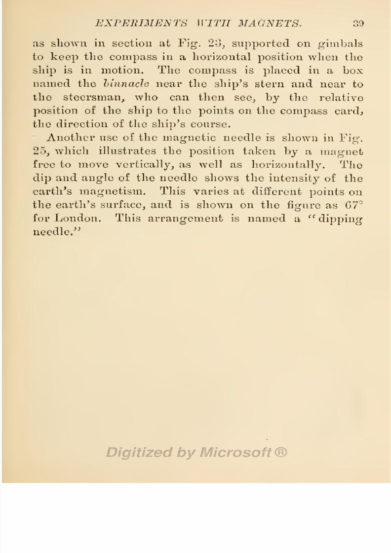
8/20/2019 electrical experiment.pdf
http://slidepdf.com/reader/full/electrical-experimentpdf 57/325
EXPERIMENTS
WITH
MAGNETS. 39
as shown
in
section
at
Fig.
23,
supported
on
gimbals
to
keep
the
compass
in
a
horizontal
position
when
the
ship
is
in
motion.
The
compass
is
placed
in
a
box
named
the binnacle
near
the
ship's
stern and
near to
the
steersman,
who
can
then
see,
by
the
relative
position
of the
ship
to
the
points
on the
compass
card;
the
direction
of
the
ship's
course.
Another
use of
the
magnetic
needle is
shown
in
Fig.
25,
which
illustrates
the
position
taken
by
a
magnet
free
to
move
vertically,
as
well
as
horizontally.
The
dip
and
angle
of
the
needle
shows
the
intensity
of
the
earth's
magnetism.
This
varies at
different
points
on
the
earth's
surface,
and is
shown on
the
figure
as
67°
for
London.
This
arrangement
is
named
a
dipping
needle.
8/20/2019 electrical experiment.pdf
http://slidepdf.com/reader/full/electrical-experimentpdf 58/325
CHAPTER
II.
EXPERIMENTS
WITH
ELECTRO-MAGNETS.
§
16.
Relation
of
Magnetism
to
Electricity.
In
the
preceding
sections
of
this
book,
we
have
been
able
to
show some
of
the
relations
which
exist
between
mag-
netism
and
electricity.
In this
chapter,
we shall
show
by
means
of
simple
experiments,
a
still
closer
relation
between the
two
forces.
To
perform
these,
we
shall
require
a
generator
of
electricity
such as
a
dynamo,
or
a
primary battery,
capable
of
giving
an
electric
current
having
a
volume
of at least
one
ampere through
a
resistance
of
10
ohms. This current
will
be furnished
by
5
or 6
cells
of the
Bunsen, Grove,
Bichromate,
or
Chromic Acid
types,
or
10
cells of
the Daniell
type,
or
one
of the
hand-power
dynamos
built
to
light
a
5
c.p.
incandescent
lamp.
A
generator
of less
power
will
serve
our
purpose
for
some of
the
experiments,
but
all
will
derive
additional
interest
from
using
a
powerful
current.
1.
The
Magnetic
Shell.
Every
conductor
of
electricity
is
surrounded
with a
magnetic
influence
enclosing
it
as
in
a
shell. An
experiment
to
prove
this
may
be
per-
formed
with
one or two cells
of
a
battery.
Get a sheet
of
notepaper,
or
any
other
smooth
paper,
and
support
40

8/20/2019 electrical experiment.pdf
http://slidepdf.com/reader/full/electrical-experimentpdf 59/325
EXPERIMENTS WITH
ELECTRO-MAGNETS.
4L
it
on a
frame or
ring
of
wood
by
glueing, pasting,
or
gumming
it
thereto,
then
pass
a
piece
of
copper
or
brass
wire
(No.
20
gauge)
through
the
centre
vertically,
and
secure the
ends
of
the
wire
to
two
metal
clips
Fig.
2G.
Magnetic
Shell around
an Electric
Conductor.
above
and below
the
paper.
Connect
these
clips
in
circuit
with the
electric
generator
or
battery, sprinkle
a
few
very
fine iron
filings
on
the
paper,
and
gently
rap
it
with
a
quill,
penholder,
or
pencil.
As
the
paper
is thus made
to vibrate
under
repeated slight
raps,
the
Fig.
27.
Magnetized
Filings
around
a
Wire.
Fig.
23.
Magnetized
Filings
over
a
Wire.
filing-s
will
arrange
themselves
around
the
wire
as
around
a
magnet,
thus
showing
that a
magnetic
influ-
ence
pervades
the
air,
and surrounds
the
wire
as
a
shell.
By
the
exercise
of
care,
the
filings
will
show

8/20/2019 electrical experiment.pdf
http://slidepdf.com/reader/full/electrical-experimentpdf 60/325
42
ELECTRICAL
EXPERIMENTS.
the exact form
and thickness of this
shell,
as
at
Figs.
27
and
30.
Fig.
29.
Horizontal
Galvanometer.
This
experiment
may
be varied
by
stretching
the
conducting
wire
horizontally
beneath the
paper,
as
shown at
Fig.
28,
and
arranging
it
to form various
Fig.
30.
Shell
of Iron
Filings
around
the
Line
Wire
of
a Powerful
Electric
Battery.
figures,
all
of
which will be
shown on
the
paper
above,
as
the
filings
arrange
themselves over
the
wire.
The

8/20/2019 electrical experiment.pdf
http://slidepdf.com/reader/full/electrical-experimentpdf 61/325
EXPERIMENTS
WITH
ELECTRO-MAGNETS.
43
wire
may
be
bare,
or
may
be
coated
with
an
insulating
substance,
without
interfering
with
the
experiment.
The
magnetic
shell
surrounding
an electric
conductor
is
also
shown
by
reference
to
Fig.
30,
which
illustrates
how
iron
filings
will
adhere to the
line
wire
of
a
powerful
battery.
If the line
wire
of such
a
battery
is carried
down
through
a
supporting
platform
of
thin
wood
or
of stout
cardboard,
we
may
test
the
extent
of
the
sphere
of
magnetic
influence
by
means of
a
small
/'
•
s
«
A
©
t
\
y
£\
Current
/V
J\
Cu-rrcnl
/„
^^
Comma
up.
^
s
Co\.na
down,*
S^H^M
s
Fig.
31.
Testing
the
Sphere
of
Magnetic
Influence
around
Electric
Conductors.
compass
or a
delicate
horizontal
galvanometer,
Avhen
the results
will
be
as shown
at
Fig.
31.
On
referring
to
this,
it will be seen
that
the
polarity
of
the
current
differs
in
the
down
line from
that of the
up
line,
and
the
compass
needle varies
its
position
as we move
the
compass.
2.
Electro-Magnetic
Induction.
Procure
or
make
a
delicate
horizontal
galvanometer
such
as
that
described
by
Mr.
Bottone
in
his book
Electrical
Instrument
Making
for
Amateurs
(Fig.
29).
Also
procure
a
few

8/20/2019 electrical experiment.pdf
http://slidepdf.com/reader/full/electrical-experimentpdf 62/325
U
ELECTRICAL
EXPERIMENTS.
yards
of
No.
22
or
No.
24
gauge
copper
wire,
and
form
two
model
telegraph
lines
running parallel
to each
other
closely,
side
by
side
without
actually
touching.
Connect
the
two
ends
of
one
line
wire
to
the
galvanometer,
and
the
two
ends
of
the other
line
wire
to
the
battery.
Im-
mediately,
on
connecting
one
line
with
the
battery,
the
galvanometer
needle
will
be
seen
to
move,
and
it will
move
again
at
the
instant
when
the wire
is
disconnected
from
the
battery,
although
the
line
in
connection
with
the
Fig.
32.
Oersted's
Induction
Apparatus.
galvanometer
does
not touch
the
line
connected
to
the
battery.
This
effect
is
produced
by
the
magnetic
shell
or
halo
surrounding
the
battery
line
inducing
a similar
condition
in the
neighbouring
wire,
much
the
same
as
a
permanent
magnet
induces
magnetism
in
iron
or
steel
in
close
proximity
to
it.
Disconnect
the
galvanometer
from
the
separate
line
and
hold
it
close
under
the
battery
line,
or
better
still
(to
prevent
vibration
of
the needle
by
tremors
of
the
hand)
fix
it in
this
position
with
the
needle
as close
as
it
can
be
got
to
the
wire,
and
let
the needle
lie
in
line

8/20/2019 electrical experiment.pdf
http://slidepdf.com/reader/full/electrical-experimentpdf 63/325
EXPERIMENTS
WITH
ELECTRO-MAGNETS.
45
with
the
wire
when
at rest.
To
do this
the
line
wire
must
be
moved
in line
with
the
magnetic
meridian
of
the
earth.
On
connecting
the line
with
the
battery,
a
movement
will be
observed
in
the
needle,
which
will
deviate
to
right
or
left of the
line
according
to
the
direction
of
the
electric
current
passing
through
the
wire.
A
compass
will
serve
this
purpose
as
well
as
a
galvanometer,
or
an
apparatus
to
show
this
ex-
periment
(shown
at
Fig.
32)
maybe
purchased
at
prices
varying
from
3s.
6d.
to 10s.
6d.
As
like
poles
repel
those
of
their
own
character,
it
naturally
follows
that
one
pole
of
the
magnetic
shell
surrounding
the
wire
must
repel
one
end
of
the
magnetic
needle
and
cause
it
to
swerve
aside
from
its
usual
position
of rest.
This
magnetic
property
of the
electric
current,
discovered
by
Oersted,
has been
made
use
of
in
the
construction
of
galvanometers
and
of
telegraph
instruments.
3.
Electro-Magnetic
Attraction
and
Repulsion.
It
has
been
shown
in
§
9
that
the
like
poles
of
permanent
magnets
repel
each
other,
whilst
unlike
poles
have
the
property
of
mutual
attraction.
Herein
was
shown
the
law
of
a
magnetic
circuit,
the
polarized
molecules
of
matter
tending
to
form
a
perfect
endless
chain.
Pre-
cisely
the
same
law
governs
an
electric
circuit.
The
polarized
molecules
of
two electric
conductors
placed
side
by
side,
attract each
other
when both
are
moving
in
the
same
direction,
but
repel
one
another
when
moving
iu
opposite
directions.
This
law,
discovered
by
M.
Ampere,
may
be
illustrated
by
means
of
an
apparatus
so
de-
vised
as
to
have
one
electric
conductor
fixed
and
the

8/20/2019 electrical experiment.pdf
http://slidepdf.com/reader/full/electrical-experimentpdf 64/325
46 ELECTRICAL
EXPERIMENTS.
other
freely
movable.
Sucli
an
appai*atus
is shown
at
Fig.
33,
named
Ampere's
Stand and
Bectangle,
costing
from
30s. to
50.<?.,
according
to
finish.
It con-
sists of a
polished
mahogany
stand,
on which is
fixed,
at one
end,
a
brass
pillar
carrying
a
projecting
arm
on
top,
terminating
in
a
mercury
cup
;
at
the
opposite
end
of
the
stand
another
brass
pillar
is
fitted,
with
a brass
clip
aiTanged
for
adjustment
to
any height,
and
made
Fig.
33.
Ampere's
Stand
and
Rectangle.
to
hold
a
flat
coil of fine insulated
wire
named
a
multiplier,
the
foot
of
the
pillar
being
fixed
to
a
sliding
plate
working
in
grooves,
for
easy
adjustment
to
any
distance
;
between
these
two
pillars
a
shorter
hollow
brass
pillar
is
fixed,
in
which a brass
piston
slides
up
or
down,
as
required,
and
bears
on
the
top
a
mercury
cup.
A
long
piece
of
copper
wire
is
bent to
form
a double
rectangular fio-ure,
as
shown
in the
sketch,
with
its lower
sides
resting
on
a
light
strip
of

8/20/2019 electrical experiment.pdf
http://slidepdf.com/reader/full/electrical-experimentpdf 65/325
EXPERIMENTS
WITH
ELECTRO-MAGNETS.
47
wood,
and ono
end
of
tlio
wire
passing
through
the
centre of
the
wooden
strip
to
the
mercury cup
beneath,
where
it is
connected
to a
suitable
pivot
point.
The
upper
end
of
this
wire
also
ends in
a
steel
needle
point,
which
pierces
a
small
hole
in
the
bottom of
the
upper
mercury cup,
and makes
contact
with
the
mercury.
The
whole
is
nicely
balanced
by
copper
balls
under the
wooden
strip,
and is
free to
move
in
a
circle
with
very
little
friction,
whilst
the
double
rectangle
of
wire
is also
electrically
connected
with the
upper
and lower
mercury
cups.
To
work
this
apparatus
we
shall
require
a
strong
current
from
a
Grove,
Bunsen,
or
Bichromate
battery
of
4
cells
arranged
in
series.
Connect
one
pole
of the
battery
to
the
long
brass
pillar,
and
the
other
pole
to
one of
the
binding
screws on the
multiplier,
then con-
nect the other
screw
of
the
multiplier by
means
of
a
piece
of wire
with
the
foot
of
the
stout
pillar.
If
the
positive
pole
of the
battery
be connected
to the foot
of
the
long
pillar,
the current
will
travei'se
the
right
limb
of
the
rectangle
in
a downward
direction,
and
will
also
traverse
the
multiplying
coil in
the
same
direction,
if
the
battery
has
been
rightly
connected.
The effect
of
this
uniform
direction
of
current
in
both
multiplier
and
wire
will
be
to
draw
the
right-hand
limb of
the
rectangle
toward the
coil,
when
both
are
brought
near
enough by
moving
the
clip
and
pillar
suppoi'ting
the
coil.
If
the
current
is
now sent
in the reverse
direction
through
the
coil,
the
wire will be
repelled.
A
series
of
very
interesting
experiments
with
similar
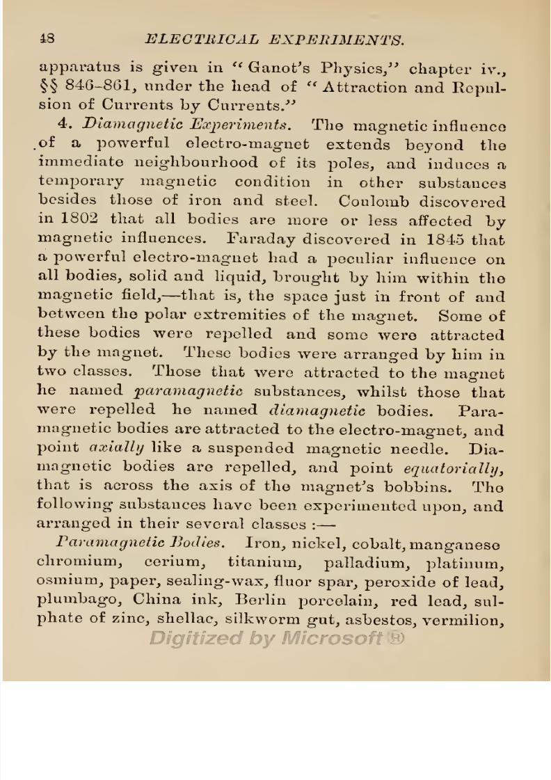
8/20/2019 electrical experiment.pdf
http://slidepdf.com/reader/full/electrical-experimentpdf 66/325
48
ELECTRICAL
EXPERIMENTS.
apparatus
is
given
in
Ganot's
Physics,
chapter
iv.,
§§
846-861,
under
the
head
of
Attraction
and
Repul-
sion of
Currents
by
Currents.
4.
Diamagnetic
Experiments.
The
magnetic
influence
.of
a
powerful
electro-magnet
extends
beyond
the
immediate
neighbourhood
of
its
poles,
and
induces
a
temporary
magnetic
condition
in
other
substances
besides
those
of
iron
and
steel.
Coulomb
discovered
in
1802
that all
bodies
are
more
or
less
affected
by
magnetic
influences.
Faraday
discovered
in 1845
that
a
powerful
electro-magnet
had
a
peculiar
influence
on
all
bodies,
solid
and
liquid,
brought
by
him
within
the
magnetic
field,
—
that
is,
the
space
just
in
front
of and
between
the
polar
extremities
of
the
magnet.
Some
of
these
bodies
were
repelled
and
some
were
attracted
by
the
magnet.
These
bodies
were
arranged
by
him
in
two
classes.
Those
that
were
attracted to
the
mao-net
he
named
'paramagnetic
substances,
whilst
those that
were
repelled
he
named
diamagnetic
bodies.
Para-
magnetic
bodies
are
attracted
to
the
electro-magnet,
and
point
axially
like
a
suspended
magnetic
needle.
Dia-
magnetic
bodies
are
repelled,
and
point
equatorially,
that
is
across
the
axis
of
the
magnet's
bobbins.
The
following
substances
have
been
experimented
upon,
and
arranged
in
their
several
classes :
—
-
Paramagnetic
Bodies.
Iron,
nickel,
cobalt,
manganese
chromium,
cerium,
titanium,
palladium, platinum,
osmium,
paper,
sealing-wax,
fluor
spar,
peroxide
of
lead,
plumbago,
China
ink,
Berlin
porcelain,
red
lead,
sul-
phate
of
zinc,
shellac,
silkworm
gut, asbestos,
vermilion,
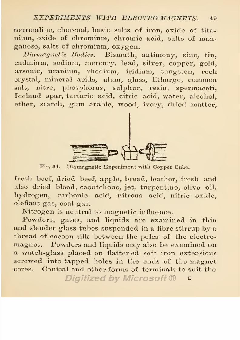
8/20/2019 electrical experiment.pdf
http://slidepdf.com/reader/full/electrical-experimentpdf 67/325
EXPERIMENTS
WITH
ELECTRO-MAGNETS.
49
tourmaline,
charcoal,
basic
salts
of
iron,
oxide
of
tita-
nium,
oxide of
chromium,
chromic
acid,
salts of man-
ganese,
salts of
chromium,
oxygen.
Diamagneiic
Bodies.
Bismuth,
antimony,
zinc,
tin,
cadmium, sodium,
mercury,
lead,
silver,
copper,
gold,
arsenic, uranium,
rhodium,
iridium,
tungsten,
rock
crystal,
mineral
acids,
alum,
glass, litharge,
common
salt,
nitre,
phosphorus,
sulphur,
resin,
spermaceti,
Iceland
spar,
tartaric
acid,
citric
acid,
water,
alcohol,
ether,
starch,
gum
arabic, wood,
ivory,
dried
matter,
Fig.
34.
Diamagnetic
Experiment
with
Copper
Cube.
fresh
beef,
dried
beef,
apple,
bread,
leather,
fresh
and
also
dried
blood,
caoutchouc,
jet, turpentine,
olive
oil,
hydrogen,
carbonic
acid,
nitrous
acid,
nitric
oxide,
olefiant
gas,
coal
gas.
Nitrogen
is
neutral
to
magnetic
influence.
Powders,
gases,
and
liquids
are examined
in
thin
and
slender
glass
tubes
suspended
in
a
fibre
stirrup by
a
thread
of
cocoon
silk between
the
poles
of
the
electro-
magnet.
Powders
and
liquids
may
also
be
examined
on
a
watch-glass
placed
on
flattened soft
iron extensions
screwed
into
tapped
holes in the ends of the
magnet
cores.
Conical and
other
forms
of
terminals
to suit the
E
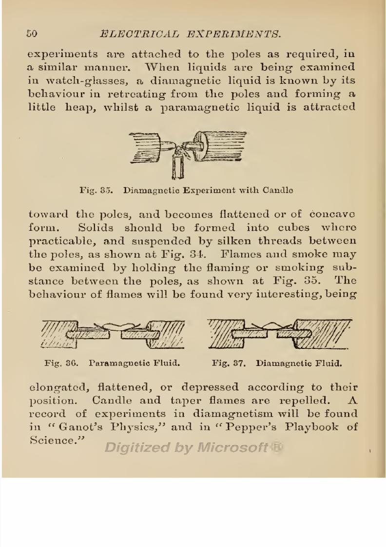
8/20/2019 electrical experiment.pdf
http://slidepdf.com/reader/full/electrical-experimentpdf 68/325
50
ELECTRICAL
EXPERIMENTS.
experiments
are attached
to
the
poles
as
required,
in
a
similar
manner.
When
liquids
are
being
examined
in
watch-glasses,
a
diamagnetic
liquid
is
known
by
its
behaviour
in
retreating
from the
poles
and
forming
a
little
heap,
whilst
a
paramagnetic
liquid
is
attracted
Fig.
35.
Diamagnetic
Experiment
with
Candle
toward the
poles,
and
becomes
flattened or
of
concave
form.
Solids should be formed
into cubes
where
practicable,
and
suspended
by
silken
threads
between
the
poles,
as
shown
at
Fig.
34.
Flames
and
smoke
may
be examined
by
holding
the
flaming
or
smoking
sub-
stance betweeu the
poles,
as
shown
at
Fig.
35.
The
behaviour
of flames
will be
found
very
interesting,
being
Fig.
36.
Paramagnetic
Fluid.
Fig.
37.
Diamagnetic
Fluid.
elongated,
flattened,
or
depressed according
to
their
position.
Candle
and
taper
flames are
repelled. A
record
of
experiments
in
diamagnetism
will be
found
in
Ganot's
Physics/'
and in
Pepper's
Playbook
of
Science.

8/20/2019 electrical experiment.pdf
http://slidepdf.com/reader/full/electrical-experimentpdf 69/325
EXPERIMENTS
WITH
ELEGTUO-MAGNETS. 51
§
17.
Simple
Electro-Magnets.
The
intimate
re-
lation
between
magnetism
and
electricity
is
most
clearly
shown
by
the
inductive
influence of
the
latter
on soft
iron,
converting
it
into
a
magnet
whilst
under
electric
influence.
If
we take a rod of
soft iron and
wind
over
it several turns
of
insulated
copper
wire,
we
may
convert
the
iron into a
magnet
at will
by
sending
a
strong
current of
electricity through
the
wire coil
wound
over
the
iron.
A
simple
electro-magnet
may
be
con-
structed
out
of
an
ordinary
French Avire
nail
and a
yard
or so of No.
24
silk-covered
copper
wire. Wind
the
wire
in
regular
turns
side
by
side around
the
nail,
and
in
regular
layers,
until
only
a
length
of
some 4
or
5
inches
has been left at
the
commencing
and
finish
ends.
Connect
these ends
to
the
battery,
and
note the
mag-
netic
condition of the nail
by
hanging
iron
brads
to its
head
as to the
pole
of
a
permanent magnet.
If
the
wire is
wound
around
a
3-inch
length
of
|-in.
iron
rod,
and about a
foot
or so of
wire
is
left at
each end
for
connection
with
the
battery,
a
number
of
interesting
magnetic
experiments
may
be
performed
(as
with
a
permanent
bar
magnet)
whilst
the
wire
coil is
connected
with the
battery
and
a
current
of
electricity
is
passing
through
the
coil.
In
fact,
all
the
experiments
perform-
able
with
a
permanent
bar
magnet
may
also
be
per-
formed
with
this
simple
electro-magnet.
In
addition to
these,
we
may
illustrate
the
fact that
the
iron
is
only
magnetic
whilst
a
current
of
electricity
is
passing
through
the
coil.
Small
iron articles
picked
up
with this
magnet
will be
dropped
instantly
when
the
electric
circuit is

8/20/2019 electrical experiment.pdf
http://slidepdf.com/reader/full/electrical-experimentpdf 70/325
52
ELECTRICAL EXPERIMENTS.
broken,
as
when the
wire is
disconnected
from the
battery.
By
the
exercise
of
a little
ingenuity
and
skill,
a
magic
wand
may
be
constructed,
with
an electro-
magnet
at
one end and a
spring
switch
at
the
other,
connection
being
made
with the
battery by
means
of
a
flexible
conducting
cord
carrying
two
wires.
The cir-
cuit can
be
completed
and
the
electro-magnet
put
in
action
by
pressing
a
spring
in the
handle.
Magnetized
Steel
Filings.
A
very
interesting experi-
ment can
be
performed
by
substituting
a
glass
tube
filled
with
steel
filings
for the iron
rod last used. Get
a
glass
tube,
stop
one end with
a
cork,
fill
the tube
with
steel
filings,
then
stop
the other end
with
a
cork.
Wind
the
insulated wire around
this
tube,
instead
of the
iron
rod,
and
send
a
strong
current
through
the
coil. The
steel
filings
will
then
exhibit
all the
properties
of
a
permanent
steel
magnet,
even after the
circuit
has
been
broken
and
the
tube
removed
from
the
coil,
if this
is
done
carefully
so
as
to
leave the
filings
undisturbed.
If, however,
we shake
the
tube,
all the
magnetic
pro-
perties
of
the
filings
at once
disappear,
because
then
north
and south
poles
of
the
particles
become
jumbled
indiscriminately
together,
and
these
neutralise
each
other.
This
experiment
has been
employed
by
science teachers
to show
the
bad effects
of
jolting
and
knocking
per-
manent
magnets.
§
18.
Horse-shoe
Electro-Magnets.
If
a
length
of
soft
iron
is
bent
into
the
form
of
a
horse-shoe
and
covered
with
insulated
copper
wire,
as shown
in
Fig.
38,
it will
be
converted
into
a
powerful electro-magnet
when
a

8/20/2019 electrical experiment.pdf
http://slidepdf.com/reader/full/electrical-experimentpdf 71/325
EXPERIMENTS WITH
ELECTRO-MAGNETS.
53
strong
current
of
electricity
is
sent
through
the
coil.
The
usual
method
of
coiling
the
wire on a
horse-shoe
electro-magnet
is
as
shown
in
Fig.
40,
—
that
is
to
say,
part
of
the
wire
is
wound
on one
limb
from left
to
right,
and
the
rest of
the
wire
is
wound on
the
other limb in
the
opposite
direction.
This
insures north
polarity
in
the
magnetism
of
one
limb and
south
polarity
in
the
opposite limb,
and,
as
opposite
poles
attract each
other,
the
magnetic
strength
of
the poles
is
much
increased
Fig.
38.
Simple
Bar and
Horse-shoe
Electro-Magnets.
by
this
arrangement.
The
polarity
of
either
limb
is
determined
by
the
direction
of
the
electric
current
pass-
ing
through
the
coil of
wire
wound
over
the limb.
For
instance,
taking
Fig.
38 as
an
illustration,
if
the
current
enters at
S
and
leaves
at
N,
S will
be
the
south
pole
and
N
the
north
pole
;
but if
the current
eaters
at
N
and
leaves
at
S,
then
N
will
be
the
south
pole
and
S
the
north
pole
of
the
electro-magnet.
The
north
pole
is
always
to
the left
of
the
current
when
flowing
in
a
coil
of wire
wound
over
an
irou
rod. This has been
era-

8/20/2019 electrical experiment.pdf
http://slidepdf.com/reader/full/electrical-experimentpdf 72/325
54 ELECTRICAL EXPERIMENTS.
pliically
represented by
imagining
a
boy lying
on
his
stomach
over
a roller
and
trying
to
move
forward.
His
forward
movement
represents
the
movement
of
the
current,
and
his
left
hand then
points
to
the north
pole
of
the
roller.
If
he turns
round
and rolls
in
the
opposite
direction,
the
poles
are
reversed.
The
polarity
of
an
electro-magnet
may
also
be
determined
by
bringing
a
compass
or
a
suspended
magnetic
needle
near
the
poles,
when
the
north
pole
of
the
needle
will
be
repelled
by
the
north
pole
of
the
magnet,
whilst
its
Figs.
39, 40,
41.
Varieties
in
forms
of
Electro-Magnets.
south
pole
will
attract
the north
pole
of
the
neecllo.
Suspend
two
magnetized
needles with
like
poles
in
front
of
a
horse-shoe
electro-magnet,
and
note
the
behaviour
of
the
two needles. One limb
of
the
magnet
will
attract
one
needle
and the
other
pole
repel
the
other
needle.
Any
of the
experiments
performable
with
a
per-
manent
horse-shoe
magnet
may
also
be
performed
with
a
horse-shoe
electro-magnet,
and
similar
experiments
may
be
performed
with it as
with a
straight
bar
electro-
magnet.
In
addition
to
these,
some
interesting experi-

8/20/2019 electrical experiment.pdf
http://slidepdf.com/reader/full/electrical-experimentpdf 73/325
EXPERIMENTS
WITH ELECTRO-MAGNETS.
55
merits
may
be
performed
in
lifting
heavy
weights
attached
to
its
armature,
attracting
the
armature
through
space,
and
noting
the distance
under
several
variations
of
current
strength.
Variations
may
also
be
made
in
the
shape
and
size
of the
magnets,
and
in the
disposition
of
the
wire coils
wound
over
the
limbs.
It is
not neces-
sary
to have
an
iron rod bent
into
horse-shoe
form
for
double-pole
electro-magnets.
The
two
cores
or limbs
may
be screwed
into
or
rivetted
in
a
heavy
yoke
of soft
iron
with
the
best
results,
—
in
fact,
this
is
the
general
form
given
to
it
in
all
electric
instruments
in
which
it
is
employed,
as
in
electric
bells,
etc.
§
19.
Electro-Magnetic
Portation.
This
term
is
used to
indicate
the
carrying
power
of
an
electro-magnet,
—
that
is,
its
ability
to
pick
up
and
carry
by
its
power
of
attraction
a
weight
attached
to
its
armature.
The
por-
tative
power
of an
electro-magnet
is
limited
by:
—
1.
The
saturation
limit of
magnetism
its cores
are
capable
of
receiving.
2.
The
number
of turns
of
wire
wound
over
the
cores,
o.
The
capacity
of
the
wire for
carry-
ing
currents.
4.
The
strength
of the current
passing
through
the
wire
coils
wound
over
its
cores.
Respecting
these
conditions
we
may
note
that:
—
1.
The
saturation
limit of
magnetism
in
pure
soft iron
is
200
lbs.
per square
inch.
Ordinary
commercial
iron
has
a
saturation
limit
forty per
cent,
below
this,
but
increased
strength
of
current
flowing
through
the coils
will
cause
iron
to
assume
a
higher
limit.
2.
The
porta-
tive
force
of
the
electro-magnet
is
increased
by
an
increased
number
of
wire
convolutions
wound
over
its

8/20/2019 electrical experiment.pdf
http://slidepdf.com/reader/full/electrical-experimentpdf 74/325
56
ELECTRICAL
EXPERIMENTS.
cores,
providing
the
thickness
of these
do
not
exceed
three
times the
diameter of
the
cores,
nor
extend
beyond
four
times
the
diameter
of
the
cores,
from
their
polar
extremities. Short
dumpy
electro-magnets
are
stronger
than
long
thin
ones
of
equal weight.
3.
As the
porta-
tive force
of an
electro-magnet depends upon
the
strength
of
the
current
passing
through
its
coils,
mul-
tiplied by
the number of
coils
themselves,
it follows
that
the
wire must have sufficient
capacity
to
carry
the
current
necessary
to
obtain
complete
saturation
of
the
iron.
The
capacity
of
any given gauge
of
copper
wire
may
be
found
by consulting
the wire
table
published
in
Induction Coils.
*
4.
The
magnetic
force
developed
in
the core of an
electro-magnet
is
governed
by
the
number
of
amperes
of
current
passing
through
its
coils,
multiplied
by
the
number
of
wire convolutions. The
magnetism
set
up
in an
iron core
is,
up
to the saturation
point, equal
to
the
number of
ampere
turns
coiled
around
it.
In
good
soft
iron
it
takes
5,000
amperes
of
electric
current
to
saturate
1
cubic
inch
of iron
with
magnetism.
If
we can
force
1
ampere
of
current
through
a
coil
of
wire
wound
around an
iron
core
5,000
times,
within
the
limits
already prescribed,
the
core will
be
saturated with
magnetism,
since each turn
carrying
1
ampere
of
cur-
rent increases
the
portative
force
of the
magnetized
core.
The
same result is
obtained from
2
amperes
of
current
through
2,500
turas,
or
5
amperes
of current
through
1,000
turns of
wire.
1
Induction
Coils,
by
G. E.
Bonney,
price
3s.,
published by
Whittaker
&
Co.

8/20/2019 electrical experiment.pdf
http://slidepdf.com/reader/full/electrical-experimentpdf 75/325
EXPERIMENTS
WITH
ELECTRO-MAGNETS.
57
Experiments
with
horse-shoe
electro-magnets
wound
with
various
lengths
and
gauges
of
wire,
may
be
tried,
and
their
portative
force ascertained
by
means
of
a
Fig.
42.
Electro-Magnet
with Wire
Leaped
on
the
Poles.
balance
scale attached
to
their
armatures
and
gradually
weighted.
Care
must
be taken
not to
greatly
exceed
the
limit
of the
carrying
capacity
of
the
wire,
or its
insulation will
be
destroyed.
When
it
is
necessary
to
wind
more
than
one
layer
of
wire
on
a
horse-shoo
magnet,
the
wire
is first
wound
on
two
bobbins
and
Fig.
43.
Powerful
Electro-Magnet
on a
Stand.
these
slipped
on
the
poles
of the
bent
iron,
or the wire
may
be
heaped
over
the
poles
of
the
magnet,
as shown
at
Fig.
42. When
the
portative
value of
an
electro-

8/20/2019 electrical experiment.pdf
http://slidepdf.com/reader/full/electrical-experimentpdf 76/325
58
ELECTRIC
A L
EXPERIMENTS.
magnet
is
to be
ascertained,
it will
be
found
convenient
to
suspend,
it
to
a
small
tripod,
as
shown
at
Fig.
44.
For
diamagnetic
experiments,
the
magnet
is fixed to
a
stand,
as
shown
at
Fig.
43.
Fig.
44.
Tiipod
for
suspending Magnets.
§
20.
Electro-Magnetic
Solenoids.
It
has
been
shown
in
previous
sections,
that
a
wire
conducting
a
current
of
electricity
is
surrounded,
by
a
shell of
mag-
netized
air. It has also been
shown
that
iron
and. steel
enveloped
in
wire
carrying
an
electric
current,
both
become
magnetized.
It has
also been
shown
that a
steel
bar
may
be
permanently
magnetized
by
placing
it
in a
coil
of
wire
through
which
an
electric
current
is
passing.
Such
a
coil
of
wire,
when
not
occupied
by
a
core
of iron or other
metal,
contains
a
core
of
air,
and.
this
core
becomes
itself an
electro-magnet,
with
poles
similar
in
every
respect
to
those
of
an
iron core
when
a
current of
electricity
is
sent
through
the
coil.
A hol-
low
coil
of
wire,
such
as
that
shown
at
Fig.
12,
§
7
}

8/20/2019 electrical experiment.pdf
http://slidepdf.com/reader/full/electrical-experimentpdf 77/325
EXPERIMENTS
WITH
ELECTRO-MAGNETS.
59
constitutes
an
electro-magnetic
solenoid.
The coil
may
be
formed
and
bound
in
the
shape
of
a
hank,
as shown
in this
figure,
or
the
wire
may
be
wound over
a
hollow
bobbin,
and
this
fixed
to
a
base.
It
is
necessary
to
thus
construct
a
solenoid
if
it is
to
be used
in
drawing
a
core
of
iron
into
itself.
The
property
of all
solenoids
is
that
of
a
sucking
action
on
cores
of
iron
free
to move
into
them.
That
is to
say,
if
a
core
of iron
is
suspended
in
a
vertical
position
over
or
under
an
open
solenoid,
and
within
the
sphere
of
its
attraction,
the
core
of
iron
will
be
sucked
into
the
coil
when
a
sufficiently
strong-
electric
current
is
sent
through
the
coil.
Experiment
a.
To demonstrate
this
sucking property
of
a
solenoid
by
means
of
an
experiment,
wind
several
turns
of
insulated
wire
(say
No.
24
silk-covered
copper
wire)
over
a
hollow
boxwood
bobbin
with
thin
sides,
and
a
smooth
bore
of
|
or
J-inch
;
fix this solenoid to a
suitable
stand,
and
suspend
close
over
its
mouth
a
short
rod
of
soft
iron
by
means
of
a thin
spiral
spring.
On
sending
a
strong
current
through
the
coil
of the
solenoid,
the
iron
will
be
drawn
into
the
coil
against
the
pull
of
the
spiral
spring.
If
the
short
iron
rod is
suspended
beneath
the
coil
by
a
filament
of silk
or
of cotton
passing
through
its
interior,
so
as
to
have
only
£-inch
of
iron
inside the
lower
mouth
of the
solenoid,
it
will
be
drawn
up
into
the
coil
whenever
a
strong
current
is
sent
through
the
wire.
The
electric
hammer shown at
Fig.
45
(a
popular
toy,
fully
described
and
illustrated
in
Amateur
Work,
Vol.
II.,
New
Series,
and
in
Work),
is
constructed
on
this
principle.
The hammer
is con-

8/20/2019 electrical experiment.pdf
http://slidepdf.com/reader/full/electrical-experimentpdf 78/325
60
ELECTRICAL
EXPERIMENTS.
structed
ou
the
model of
a
Nasmyth
steam
hammer,
with a
soft
iron
piston
working
in
a
brass
cylinder
wound
with
some
three or four
layers
of
silk-covered
wire.
When
a current
from
four
Bunsen
cells
is sent
through
this
coil,
the
piston
is
sucked
up
into
the
solenoid,
and
in so
doing
moves
a
lever
which
discon-
nects
the
current
and
allows
the
hammer
to fall.
In
Bowron's
Electric
Hammer.
falling
it
strikes
the
lever,
and
again
closes
the
circuit,
and
in
this
way
the
up
and down
motion
of
the
piston
is
ensured.
This
model
electric
hammer
is
sold
by
Mr.
G-.
Bowron,
Praed
Street,
London.
The
sucking
action
of
solenoids
has
also
been
utilised
in
regulators
for such
electric
arc
lamps
as
the
Pilsen
lamp,
and
in
the
con-

8/20/2019 electrical experiment.pdf
http://slidepdf.com/reader/full/electrical-experimentpdf 79/325
EXPERIMENTS
WITH ELECTROMAGNETS.
61
struction
of
ammeters
and similar
measuring
instru-
ments.
b.
The solenoid
has also some
other
interesting
pro-
perties.
As
might
be
expected,
from
the
fact
that
its
hollow
core
of air
has
similar
polar
extremities
to those
of
an
electro-magnet
made
of
iron,
these
poles
behave
much
the
same
as those of
a
magnet,
the
north
pole
of
the
solenoid
repelling
the
north
pole
of a
permanent
Fig.
4G.
Apparatus
for
showing
the
Magnetic
Poles
of
a
Solenoid.
magnet,
like
poles
of two
solenoids
repelling
each
other;
and
solenoids,
free
to
move
in
the
magnetic
meridian
of
the
earth,
place
themselves
with their
ends
pointing
due
north
and
south,
thus
showing
that
they
are
subject
to
the
directive
influence
of the
earth's
magnetism.
c.
A
Helix
of
wire
will
serve
the
purpose
in
experi-
ments
with
solenoids
to
demonstrate
their
magnetic

8/20/2019 electrical experiment.pdf
http://slidepdf.com/reader/full/electrical-experimentpdf 80/325
62
ELECTRICAL
EXPERIMENTS.
properties.
A
helix
is
a
hollow
spiral
of
wire,
like a
spiral
spring,
obtained
by
winding
a
smooth
cylinder
(such
as a
pencil
or
ruler)
with
wire,
and
slipping
the
coil
of
wire
off
when
wound.
Silk-covered
copper
wire
of
from
No.
20
to
No.
24
gauge
will be found most con-
venient for this
purpose.
A
helix
of
wire thus
formed,
and
furnished
with
connecting
sockets at
the
ends,
is
shown
at
Fig.
47.
An
interesting
experiment
may
be
performed, according
to
Professor
A.
Bain,
with
a
helix
thus
constructed
and
arranged,
which
will
serve
to
illustrate
magnetic
suspension.
If
a
small
steel
perrna-
Fig.
47.
nent
magnet
is
inserted
in
such a
helix,
and a
strong
current
of
electricity
is
sent
through
the
wire,
the
bar
magnet
will
rise
and
take
up
a
position
in
the
middle
of
the
helix,
as
shown
in
the
figure.
d.
When
such
a helix
is
suspended
to a
frame,
as
shown
at
Fig.
4G,
with the
terminals
of the
solenoid
dipping
into
cups
or
troughs containing
mercury,
a
current
of
electricity
can
be sent
through
the
helix,
converting
it
into
a
magnet,
which
is
then
free
to
move
and
take
up
a
position
pointing
north
and
south,
as an
ordinary
magnet.
e.
A
very
interesting experiment
may
be
easily per-

8/20/2019 electrical experiment.pdf
http://slidepdf.com/reader/full/electrical-experimentpdf 81/325
EXPERIMENTS
WITH
ELECTRO-MAGNETS.
63
formed
with
a
lielix
of
fine
copper
wire
not
insulated.
Connect
one end
of
the
wire
helix
to
a
horizontal
arm
of metal
in
contact
with
one
pole
of
the
battery,
and
allow
the
lower
end
of
the lielix
to
lightly
dip
into
a
metal
cup containing
mercury,
connected
to the
opposite
pole
of
the
battery.
On
sending
a
current
through
the
helix,
its coils
will
be
seen
to
contract,
and the
lower
end
will be drawn
out
of the
mercury,
thus
breaking
the electric
circuit.
When
the
current
ceases
to
pass
through
the
helix,
its
coils
again expand
and
drop
the
Fig.
48.
Divided
Iron
Ring.
lower
end
again
into
the
mercury
cup.
This completes
the
circuit,
and
the
same
movement
is
repeated,
thus
making
and
breaking
the
circuit
by
a
jumping
motion
of the
coils.
This
interesting
movement
of
the
helix
ia
caused
by
the
mutual
attraction
of
the
coils
when
a
current
is
passing
through
them,
and is
utilised
in con-
structing
contact
breakers
for
induction
coils.
§
21.
Magic
Magnetic
Rings.
An
amusing
and
interesting
experiment,
illustrating
the
attractive
influ-
ence
of
solenoids
and their
magnetic
power,
may
be
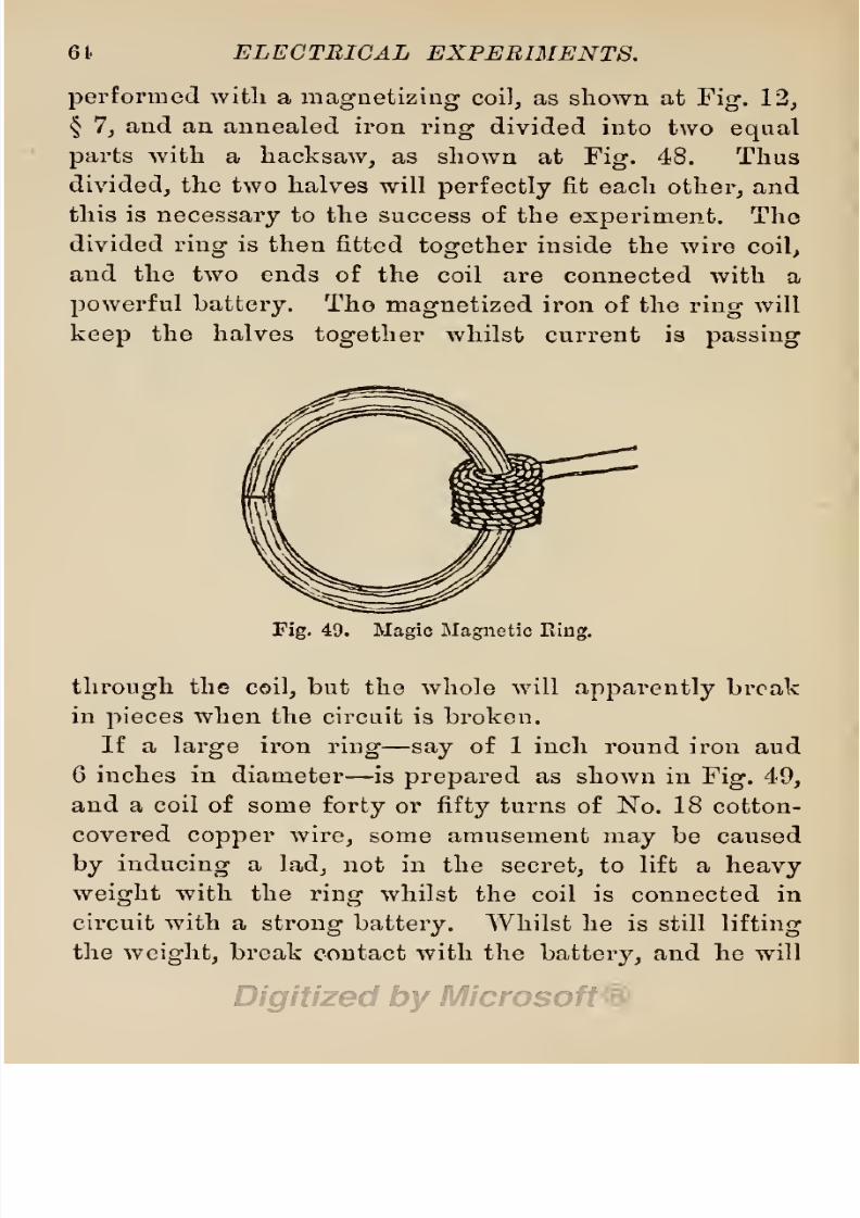
8/20/2019 electrical experiment.pdf
http://slidepdf.com/reader/full/electrical-experimentpdf 82/325
64
ELECTRICAL
EXPERIMENTS.
performed
with
a
magnetizing
coil,
as
shown
at
Fig.
12,
§
7,
and an
annealed
iron
ring
divided
into
two
equal
parts
with
a
hacksaw,
as shown
at
Fig.
48.
Thus
divided,
the
two
halves will
perfectly
fit
each
other,
and
this is
necessary
to
the
success of the
experiment.
The
divided
ring
is then
fitted
together
inside the wire
coil,
and
the
two
ends
of
the coil
are connected with a
powerful
battery.
The
magnetized
iron
of the
ring
will
keep
the
halves
together
whilst current
is
passing
Fig.
49.
Magic
Magnetic
Ring.
through
the
coil,
but
the whole
will
apparently
break
in
pieces
when the
circuit
is
broken.
If a
large
iron
ring
—
say
of
1
inch
round iron aud
6
inches in
diameter
—
is
prepared
as
shown
in
Fig.
49,
and
a
coil
of
some
forty
or
fifty
turns
of
No.
18
cotton-
covered
copper
wire,
some amusement
may
be caused
by
inducing
a
lad,
not
in
the
secret,
to
lift a
heavy
weight
with the
ring
whilst
the
coil is
connected
in
circuit
with a
strong
battery.
Whilst
he
is
still
lifting
the
weight,
break
contact
with
the
battery,
and
he
will

8/20/2019 electrical experiment.pdf
http://slidepdf.com/reader/full/electrical-experimentpdf 83/325
EXPERIMENTS
WITH
ELECTRO-MAGNETS.
65
appear
to have broken the
ring.
Or
get
two
lads
to
each
hold
a
half
of the
ring
and
gently
pull,
then
sud-
denly
break
contact,
and
note
their
consternation
at
the
broken
ring.
§
22.
Magic
Magnetic
Hemispheres.
This
experi-
ment,
together
with
that
mentioned
in
the
last
sec-
Fig.
50.
Magic
Magnetic
Sphere.
tion,
is
a
modified
form
of one
published
in
1847,
and
reproduced
in
Electric
Toy
Making.
The
experi-
ment
is
performed
with
two
hemispheres,
or
cups
of
annealed
iron,
each
fitted
with
an
annealed
soft
iron
core,
one of which is
furnished
with
a coil of
wire,
as
shown
in
section
at
Fig.
51,
thus
forming
an
electro-
p

8/20/2019 electrical experiment.pdf
http://slidepdf.com/reader/full/electrical-experimentpdf 84/325
66
ELECTRICAL
EXPERIMENTS.
magnet.
The ends of
the coil
of wire
may
be
brought
through
holes
drilled
through
the
crown
of
the hemi-
sphere,
as
shown
in
the
sketch,
or
brought
out
through
two
slots
cut
in
the rims.
The two
hemispheres
should
be furnished
with
rings,
as
shown
in
Fig.
50,
and
the
coil
placed
in
circuit with a
powerful
battery.
If
every
part
has
been
well
fitted,
some
amount
of
force
will
have
to
be used
in
pulling
the
two
cups
apart
when
Fig.
51.
Section
of
Magic
Magnetic Hemisphere.
current
is
passing
through
the
coil,
but
they
will
sepa-
rate
easily
when
the
circuit
is
broken.
§
23.
Uses
of
Electro-Magnets.
These
are
nume-
rous,
and would
fill a
long
list,
since
a
large
num-
ber of electrical
instruments owe
their
usefulness
to
electro-magnets.
Horse-shoe
electro-magnets
are em-
ployed
in
the
construction
of
electric
bells.
A
full
description
of
these is
given
in
Electric
Bells
: and
All
About
Them,
a book
published
by
Messrs.
Whittaker
&
Co.
at the
price
of
three
shillings. Electro-magnets

8/20/2019 electrical experiment.pdf
http://slidepdf.com/reader/full/electrical-experimentpdf 85/325
EXPERIMENTS
WITH ELECTRO-MAGNETS.
67
in
several forms are
employed
in
the
construction
of
dynamo-electric
machines. These are
briefly
described
by
Mr. Bottone in
Electrical Instrument
Making
for
Amateurs/'
l
and
more
fully
in
another
book
by
the
same
author,
on
The
Dynamo
:
How
Made
and Used.
Fig.
52.
King,
Mendham
& Co.'s Electro-Motor.
Electro-motors,
are
machines
constructed
with
electro-
magnets.
These
are
described
in a
little volume
by
Mr.
Bottone
on
Electro-Motors
:
How
Made and
Used.
*
The
cores
of
induction
coils
are electro-
magnets,
and
also the
automatic
breaks
of
these
in-
struments,
described
in the
author's
book
on
Induction
Coils.
1
The
Morse
sounder,
which
has
worked
a
complete
revolution
in
telegraphy
since
its
introduction,
is
also
an
electro-magnet.
1
All
these
books
are
published
by
Whittaker
&
Co.

8/20/2019 electrical experiment.pdf
http://slidepdf.com/reader/full/electrical-experimentpdf 86/325
CHAPTER
III.
EXPERIMENTS
WITH
INDUCTION
COILS.
§
24.
Spark
Induction
Coils.
It
lias
been
shown
in
the
previous
chapter,
that
an
electric
current
passing
through
a wire
conductor,
develops
therein a
magnetic
condition
which exerts an
influence on
the
air
surround-
ing
the
wire,
converting
it
into a
magnetic
shell.
It
has
also
been shown
that
this
magnetic
influence is
transmitted
to
another
wire
conductor
running
parallel
to
the
current-
carrying
wire,
if
the
two
wires
are
placed
close
together
without
touching
each
other.
If
the
current-carrying
wire
is
wound
in
the
form
of
a
helix,
each
turn
increases
the
electro-motive
force of
the
current
passing
through
the
wire,
because
each
turn
magnetizes a
core
of
air,
and
the
magnetic
influence
of
this
is transmitted
to the
neighbouring
turn
of
wire. If
an
insulated
wire
is
wound over
the
helix
of
wire
in
the
same
direction,
a much
stronger
magnetic
influence
is
felt,
so to
speak,
in
the second
or
outside helix of
wire
than
would
be
experienced
if
the
two
wires
were
merely
laid
along
parallel in
straight
lines
side
by
side.
If
the
wire helix
is wound
over a
core
and
doubled
on
itself so
as
to
form
a double
helix,
and
many
folds
of a much
finer wire
is
wound
over
this,
a
current of
very high
68

8/20/2019 electrical experiment.pdf
http://slidepdf.com/reader/full/electrical-experimentpdf 87/325
EXPERIMENTS
WITH INDUCTION COILS.
69
tension
is
induced in
the
second
wire,
rind a
coil thus
constructed,
is
named
an
induction
coil.
By
properly
arranging
the
wires
and
adding
an
apparatus
to
auto-
matically
intercept
the even
flow of
the
current
in
the
first
helix,
an
induction
coil
may
be
built
to so
enor-
mously
increase
the
tension
of the induced
current
in
Fig.
53. A
Spark
Induction
Coil.
the
second coil
as
to break
forth from
the ends
of
this
coil
in
the
form
of a
number
of
snapping sparks,
when
the two
ends
are
brought
close
together.
Such
an
apparatus
is
named a
spark
induction
coil. This
has
been
fully
described and
illustrated in
another
book,
Induction
Coils,
published
by
Messrs. Whittaker &
Co.
at
the
price
of
three
shillings.

8/20/2019 electrical experiment.pdf
http://slidepdf.com/reader/full/electrical-experimentpdf 88/325
70
ELECTRICAL EXPERIMENTS.
§
25.
Experiments
with
Spark
Induction Coils.
In
the
book
mentioned in the
preceding
section,
the
author
could
not,
for
want
of
space,
describe
the
many
experiments
which
might
be
performed
with
spark
induction coils.
Some
of
the most
simple
may
be
performed
with
the
coil
alone,
or
with
the
aid
of
simple
home-made
apparatus
;
but
others
can
only
be
per-
formed
by
the aid
of
other
apparatus,
which
must
be
bought
at
a
high
price,
or
made
by
the
amateur
himself.
To do
the
latter,
he must know how
to
work
the
materials,
and
this
knowledge
can
only
be
obtained
from detailed and illustrated instructions. These
are
given
in
succeeding
sections.
Some
of
the most
simple
experiments
with a coil
giving
an inch
spark
through
air,
maybe
performed
by
the
aid
of
a
Henley
discharger,
described
in
the
next
section.
§
26.
Experiments
with
Henley's
Discharger.
In
the
ordinary
form of
spark
induction
coil,
the
ends
of
the
secondary
wire are
attached to
two
binding
screws
on
the cheeks
of the coil
bobbin,
or on the
sup-
porting
base
of
the
coil.
Wires
are led
off
from
these
screws
to
the
apparatus
in
use
with the
coil.
One
such
apparatus
is
a
Henley's
discharger,
so named
after the
name
of
its inventor.
This
apparatus
consists
of
two
vertical
pillars
of
glass
or
ebonite
cemented
into
brass
sockets
fixed
to the base-board of a
coil,
or
to
an
inde-
pendent
base-board,
at
distances
of
6
inches
or
more
apart.
Each
pillar
is
furnished
with a head of
brass or
other
metal,
in
which is
a
hole
holding
a
slide
rod
of
brass
or
German
silver fitted
with
an
insulating
handle

8/20/2019 electrical experiment.pdf
http://slidepdf.com/reader/full/electrical-experimentpdf 89/325
EXPERIMENTS
WITH
INDUCTION
COILS. 71
of
ebonite,
or
(as
in
the
best-made
instruments)
either
a
swivel
joint
or a
ball-and-socket
joint,
holding
a
similar
slide
rod.
The
sliding
rods
must
have
insulating-
handles
to
protect
the
operator
from
violent and
danger-
ous
shocks.
The
tips
of
the
rods
should
be
made like
pencil
holders,
to
hold
small
pencils
of
metal
wire,
and
the
rods
should
be
so
arranged
as to
be
in
contact
at
their
tips
when
thrust
into their
socket
holders,
or
when
Fig.
54.
Henley's
Discharger
for
Spark
Coils.
deflected
at
an
angle
over
the
operating
table
placed
between
them.
Provision
must be
made for
connecting
these
sliding
rods with
the terminals
of
the
secondary
wire of
the
coil,
and
this
is
best
done
in the
ferrules
of
the
handles
or in the heads
through
which
the
rods
slide.
In
best-made
apparatus,
a small
ebonite
table,
8x2
inches,
is
fixed on an
insulating pillar
of
ebonite
or
glass,
midway
between
the
supporting
pillars
of
the
discharger.
If
the
discharger
rods
can
only
slide
to

8/20/2019 electrical experiment.pdf
http://slidepdf.com/reader/full/electrical-experimentpdf 90/325
72
ELECTRICAL
EXPERIMENTS.
and
fro
with
a
horizontal
movement,
this table
should
be
fixed
to a
stem
sliding
in a
hollow
pillar
arranged
for
adjustment
to
any
height,
but
the
table
may
be
fixed
as
shown in
Fig.
54,
if
the rods
are
furnished with
pivoted,
or
ball-and-socket
joints.
This
table
is
used
to hold
substances
whilst
the
spark
is
passed
through
them.
1.
Deflagration
of
Wire.
Deflagration
experiments
are
among
the
most
simple
that can
be
performed
with
a
good
spark
coil and a
Henley's
discharger,
a.
Fix
two
short
pieces
of
iron
wire
in
the
ends of the dis-
charging
rods,
connect
the
dischargers
to
the
secondary
terminals
by
two
lengths
of
copper
wire,
set
the
coil
in
motion,
and
bring
the
ends
of
the
dischargers
together
until
sparks
pass
freely
between
them.
b.
Lessen
the
distance
between the
points
until one
piece
of
iron
wire
becomes
white
hot,
when
it will
burn
vividly
and
emit
bright
sparks
of
burning
metal,
c.
Switch
the coil out
of
action,
remove
the
unburnt iron
wire,
and
substitute
copper
wire,
then
repeat
the
experiment,
and
note the
difference,
d.
Procure specimens
of
other
metal
wires
and
repeat
the
experiments
with
them.
Each
different
metal,
and
some of
the
different
alloys,
will
give
sparks
of a
different
colour.
2.
Deflagration
of
Metal
Filings.
Place a
piece
of
ebonite,
or
of
gutta-percha,
on
the
insulated
table be-
tween
the
dischargers,
and
sprinkle
a
layer
of
finely
sifted
metal
filings
over
the
surface,
switch
the coil
into
action,
and
bring
the
points
of
the
dischargers
to
the
edge
of
the
filings
on
each
side.
Some of
the
filings

8/20/2019 electrical experiment.pdf
http://slidepdf.com/reader/full/electrical-experimentpdf 91/325
EXPERIMENTS
WITH
INDUCTION
COILS.
73
will
be
fired,
and the
zigzag spark
will
receive
a
colouring
characteristic
of
the
metal
being
fired.
Various
metal
filings
should be
tried,
and
mixtures
of
the
several
metals
will
give
a
variety
of
results.
3.
Deflagration
of
Metal
Foil.
Lay
a
smooth
white card
or
a
sheet
of
smooth
white
paper
on
the
ebonite
table,
and
place
on
it
a
scrap
of
silver
foil.
On
bringing
the
points
of the
dischargers
to
the
edges
of
the
foil,
it
will
disappear
with
a flash of
light,
and stain the
paper
or
card.
By
using
a
new
card
with
each,
this
experiment
may
be
repeated
with
gold
leaf,
dutch
metal
foil,
copper
foil,
and other
thin
leaf
metal,
the colour
of
the
flash
varying
with
each
metal.
4.
Electric Stencils.
Place
a sheet of
tinfoil
on
the
table,
and
in connection
with one of the
discharging
points.
Lay
a
sheet of note
paper
on
the
tinfoil,
and
bring
the
other
discharger
point
to bear
on
the
paper.
Spai'ks
will
pass
through
the
paper
and
perforate
it with
cleanly
pierced,
charred
holes.
By
tracing
a
pattern
or
words
on
the
paper
with
a
pencil,
and
moving
the
paper
under
the
discharger
point
to
follow
the
pencil
tracing,
a
stencil
may
be
thus
prepared.
Thin
card
may
be
employed
instead
of
paper,
but
more
time
must
be
allowed
for
the
sparks
to
pierce
the
card.
A
por-
table
insulated
discharger
connected
to
the
secondary
terminal
by
flexible
wire
cord,
may
be
used
as
a
stylus
with
advantage
in this
and similar
experiments.
5.
Electric Stars,
a.
Lay
a sheet
of
glass
on
the
table,
and on
this
a
sheet of
tinfoil
in
contact
with
one
of
the
discharger
points.
Set
the coil
in
action,
and

8/20/2019 electrical experiment.pdf
http://slidepdf.com/reader/full/electrical-experimentpdf 92/325
74
ELECTRICAL
EXPERIMENTS.
bring
the
other
discharger
point
down
to
the
centre
of
the tinfoil
plate
within
striking
distance.
The
stream
of
sparks
will
break
up
into
diverging rays,
and
per-
form
a
sinuous movement
over
the
tinfoil,
b.
Remove
the
tinfoil and
slightly
moisten the
surface
of
the
glass,
then
bring
the
points
to
bear
on
the
moistened
surface
within
striking
distance.
The
sparks
will
ap-
pear
to be
longer,
and
assume a
zigzag
form,
whilst
here and
there
they
will
break
up
into little
points
of
light.
Fig.
55. Bent
Wires
ou
Ends of Fixed
Discharger.
6.
Arborescent
Figures.
Smoke
a
metal
plate
until
its
surface
becomes
dead
black,
then
lay
it
on
the
table
with its
blackened
surface
uppermost,
and its
edge
in
contact
with
one of
the
discharger
points.
Over
the
metal
plate,
place
a
sheet of
clean
glass
or of mica.
Place
a
piece
of
wire
in
the
other
discharger point,
and
bend it so
as to
bring
its end
vertically
on
the
centre
of
the
glass
plate,
then
surround
it
with a
tiny
pool
of
water. When
the coil
is
set
in
action,
this
little
pool
will
appear
to
grow,
shooting
out
branches in all
direc-
tions,
until,
after
some
time,
the
whole
plate
of
glass
or of
mica
appears
covered with
beautiful
arborescent

8/20/2019 electrical experiment.pdf
http://slidepdf.com/reader/full/electrical-experimentpdf 93/325
EXPERIMENTS
WITH
INDUCTION
COILS.
75
figures.
If a
plate
of
glass
and a
plate
of
mica
are
procurable,
they may
be
used
alternately,
different
patterns
being
produced
on
plates
of
different
material.
The
patterns
may
also
be varied
by
employing
various
acid and saline
solutions.
This
experiment
has been
named
Dr.
Wright's
cohesion
experiment,
and has
been
described
as
such
in
Intensity
Coils
by
Dyer.
If
the
discharger
has not been
provided
with
ball-and-socket
joints,
or
pivoted
joints,
this
and
the
preceding
ex-
periments may
be
performed
with
wires
placed
in
the
discharger
points,
and bent
down,
as
shown
at
Fig.
55,
or
one of
the rods
may
be
removed
from its
supporting
pillar,
and
held
in
the
hand,
or
supported
from
a
hori-
zontal
arm
over
the
plate,
or
a
portable
discharger
rod
may
be
used
for
the
purpose.
7.
Fire
from
Water,
a. Connect
a
length
of
soft
No.
24
copper
wire
to
one of the
discharger
rods,
dip
the
other end
into a
glass
of
drinking
water,
and
bring
the
end of the
other
discharging
rod
near
the
surface
of
the water.
Vivid
sparks
will
appear
to rise
from
the
water
when
the
coil
is
in
action.
If
a
special
glass
is
prepared
by
drilling
a
hole
through
the
bottom,
and
cementing
a
piece
of
wire
in
the
hole,
and this
is
secretly
connected
with
the
discharger
point,
the
result
will
appear
magi-
cal,
as
if
fire
was
obtained
from
water,
b.
To sIioav
that
water
is
a
bad
conductor,
and
moist
air
superior
to
either
dry
air
or
water,
make
a
small
pool
of
water
(in
the
shape
of
a
large drop)
on
a
plate
of
glass,
and
bring
the
discharger
points
down
to
the
margin
of
the
pool
on
opposite
sides.
The
sparks
will
pass
over
the
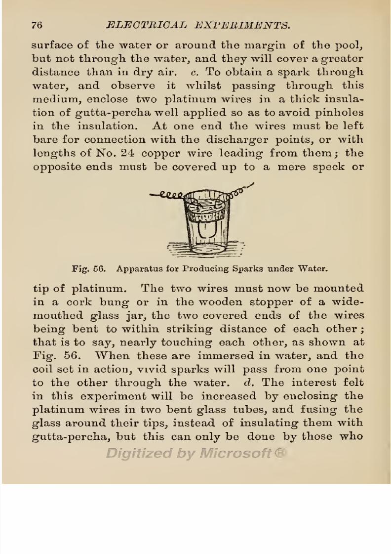
8/20/2019 electrical experiment.pdf
http://slidepdf.com/reader/full/electrical-experimentpdf 94/325
76
ELECTRICAL
EXPERIMENTS.
surface
of the
water or
around the
margin
of
the
pool,
but
not
through
the
water,
and
they
will
cover
a
greater
distance
than
in
dry
air. c. To
obtain
a
spark
through
water,
and
observe
it
whilst
passing
through
this
medium,
enclose
two
platinum
wires
in a thick
insula-
tion of
gutta-percha
well
applied
so
as
to
avoid
pinholes
in
the insulation. At one end
the
wires
must
be left
bare
for
connection with
the
discharger
points,
or
with
lengths
of
No.
24
copper
wire
leading
from
them
;
the
opposite
ends
must
be
covered
up
to
a
mere
speck
or
Fig.
56.
Apparatus
for
Producing
Sparks
under
Water.
tip
of
platinum.
The two
wires must
now be
mounted
in
a
cork
bung
or in
the
wooden
stopper
of
a
wide-
mouthed
glass
jar,
the two
covered ends
of
the
wires
being
bent
to within
striking
distance of
each
other
;
that
is to
say,
nearly
touching
each
other,
as
shown
at
Fig.
56.
When
these are
immersed
in
water,
and the
coil
set
in
action,
vivid
sparks
will
pass
from
one
point
to the
other
through
the
water, d.
The
interest
felt
in
this
experiment
will
be
increased
by
enclosing
the
platinum
wires
in
two bent
glass
tubes,
and
fusing
the
glass
around
their
tips,
instead
of
insulating
them
with
gutta-percha,
but
this
can
only
be
done
by
those
who

8/20/2019 electrical experiment.pdf
http://slidepdf.com/reader/full/electrical-experimentpdf 95/325
EXPERIMENTS
WITH
INDUCTION
COILS. 77
have
had some
experience
in
the
manipulation
of
glass.
Glass
is almost
an
invisible insulator
of
electricity,
con-
sequently
the
insulation of
the
platinum
wires will
not
be
so
apparent
as
when
coated with
gutta-percha.
8.
Oily S^HM'ks.
a.
Put
a
drop
of oil
on
each
dis-
charger
point,
and
bring
them
close
together
without
touching.
The
sparks
will
then
be
intensely
green,
and
their tint be
modified
by
varying
the
distance
be-
tween
the
points,
b.
Oil
may
also
be
employed
instead
of
Avater to
demonstrate
the
comparative
conductivity
of these
mediums.
If
a
drop
or
globule
of
oil
be
placed
on
a
glass
plate,
and
one
of
the
discharger
points
brought
close to
its
margin,
the
static
charge
of
the
coil
will
be
manifested
by
the
troubled
surface of
the
oil,
which
will
appear
as
if
in
a
state
of
effervescence.
On
bringing
down the other
point
to
the
opposite
side
of
the
oil-spot,
this
effervescence
will
be
increased,
and
flashes
of
light
will
appear,
but
no
sparks
will
pass.
After
some
little
time,
one
side
of
the oil
spot
will
become
dry,
and
this
drying process
will
go
on
until
only
a thin
film
is left on
the
plate.
This
superior
re-
sistance
of
oil
has
led
to
its
adoption
as
an
insulator
for
the
coils
of
transformers,
and
also for
large
induction
coils.
9.
Superior
Conductivity
of
Hot
Air. a.
Arrange
the
discharger
points
to
give
the
ordinary
spark
in
air,
set
the
coil
in
action,
and
bring
a
lighted
taper
near
the
line
of
sparks
at one
side.
The stream of
sparks
will
diverge
toward
the
flame,
and
will
lose some
of
their
brilliancy.
b. Hold the
taper
under
the stream
of

8/20/2019 electrical experiment.pdf
http://slidepdf.com/reader/full/electrical-experimentpdf 96/325
78 ELEGTBIGAL
EXPERIMENTS.
sparks,
and
allow
thein to
pass
through
the heated air
whilst
the
points
are
being slowly
drawn farther
apart.
The
superior conductivity
of
the
heated
air
will
be
shown
by
the
increased
length
of
spark.
Its
character
will also
be
changed
from
the
usual
violet hue
and
compact
beady
form,
to
a
loose
flame
of
a
blue
tint,
c.
Bring
the
points
closer
together,
so
as
to
obtain a
fiery
red
spark,
then
hold
the
lighted
taper
in
such
a
position
as
to
pass
the
sparks
through
the
wick,
when
thev
will
become
white,
and
of
an
ovate
form.
d.
Raise
the
taper
a
little,
and
separate
the
points slowly.
The
sparks
will
appear
to
travel
around
the
wick,
and
form a
blue
stripe
in
the flame,
e.
Smoke
the
points
and
bring
them
close
together.
The carbon will
be-
come
incandescent,
and
the two
points glow
like white
stars.
/.
Blow
out
the
taper
and
hold
the
red-hot
wick
in
the
stream
of
sparks.
The
taper
will
be
immediately
relighted,
g.
Connect one
of
the
dischargers
with
a
Bunsen
burner
by
means
of
a fine
wire,
and
hold
the
other over
the
burner,
light
the
burner,
bring
the
point
of
the other
discharger
over
the
flame,
and lower
the
point
until
sparks
are
seen
to
pass
from
it
through
the
flame
to the tube
of
the
burner.
Rub
two
lumps
of
salt
together
near
the
foot of the
burner.
The flame
will
change
from
blue
to
a
brilliant
yellow,
and
will
then conduct
the
sparks
better.
10.
Modified
Forms
of
Sparks.
The
form
of the
sparks
from an
induction coil
may
be modified
in
several
ways.
a. The stream
may
be bent
out
of its
course
by
interposing
a
piece
of thick
gutta-percha,
8/20/2019 electrical experiment.pdf
http://slidepdf.com/reader/full/electrical-experimentpdf 97/325
EXPERIMENTS
WITH
INDUCTION
COILS.
79
when the
sparks
will
be seen
to
travel
around
the
edge
of
the
gutta-percha,
b.
If the
sheet of
gutta-percha
be
thin,
and
the
discharger
points
brought
closer
together,
the
sheet
will
become
softened,
and
the
sparks
assume
a
zigzag
form as
they
pass
through
it.
c.
If
a
piece
of
copper
wire
bent
in
the
form
of
a
T or
L,
is
inserted
in
one
discharger,
and the
point
of
the
other
is
brought
near
the
copper
wire so
as
to
send
the
sparks
against
the
side
of
it,
they
will
assume
a brush-
like
form.
d.
By
substituting
a
wire with
a
metal
bead
or
ball
at
the
end
for
the
ordinary
discharger point,
another form
of
brush
spark
will be
produced,
e.
If
a
small concave
metal
shield
be
soldered
to
a
wire,
and
substituted
for
the
metal
ball,
the
spark
will
be
again
modified
in
form,
and be
accompanied
by
a
loud
snap-
ping
sound.
/.
By
blowing
on
the stream
of
sparks
with
a
mouth
blowpipe,
a
glass
tube,
or a
pair
of
bellows,
a
sheet
of
flame
will
be formed on
the
opposite
side,
and an
appearance
produced
as
of luminous
air.
11.
Ignition
Experiments,
a.
Place a
few
drops
of
sulphuric
ether
on a
tuft of
cotton
wool,
and
put
this
on
the
small
ebonite
table
between
the
points
of the
dischargers.
On
setting
the coil
in
action
and
bringing
the
discharger
points
near
each other
with
the
wool
between,
the
ether
will
be
at
once
ignited,
b.
Some
lycopodium
powder
sprinkled
over
cotton
wool
may
be
ignited
in
a
similar
manner,
and
gunpowder
may
be
thus
exploded
in
small
quantities,
c.
If
a
small
tuft
of
gun-cotton
be
placed
on
a
wire and held
in
the stream
of
sparks,
it
will
explode
with
a feeble
report.
Only

8/20/2019 electrical experiment.pdf
http://slidepdf.com/reader/full/electrical-experimentpdf 98/325
80 ELECTRICAL
EXPERIMENTS.
very
small
quantities
of these
explosives
should be
taken
at
a
time. d.
A
piece
of
phosphorus
the
size
of
a
pea,
placed
on the back
of
a
plate
or
saucer,
may
be
similarly
ignited
by
the stream of
sparks
;
but I
do
not
advise
the
experiment,
since
phosphorus
is
liable to be
inflamed
by
the
hand,
when
it
will
cause
painful
burns
which
heal
slowly,
and,
the
fumes
of
burning
phosphorus
are
poisonous.
12.
Impulsion
Sparks.
The
sparks
which
pass
be-
tween the two
discharger
points
from an
induction
coil,
are
merely
particles
of
air
set
in
rapid
motion
by
the
vibratory
action
of
the
force we are
pleased
to
name
electricity.
The
light
and
heat
obtained
from
these,
is
due
to
the
friction of
the
rapidly
impelled
particles
against
each
other,
and
against
other
substances
placed
in
their line
of
action.
If
little
or
no resistance is
offered
to
their
motion,
little or
no
heating
or
lighting
effects
will be observed. To
illustrate
this
fact,
place
a
small
quantity
of
very
fine boxwood
saw-dust,
lycopo-
dium,
flour
of
sulphur,
or
other
light
non-conducting
powder
on
a
plate
of
opal glass,
and
form
it
into
a
small
heap
or
mound,
the
size of
which must
depend
upon
the
length
of
spark
to be used
on
it,
since the diameter
of the
heap
must
slightly
exceed
the
length
of
the
spai-k.
Place
the
points
of the
dischargers
lightly
in
contact
with
the
margins
of the
heap
on
opposite
sides,
and set
the coil
in action.
The
sparks
will
only
set
the
particles
of
powder
in
motion,
but
will
not
inflame
them.
The
vibratory
action
of
the
current
can be
readily
traced
by
means of
this
experiment,
the
particles

8/20/2019 electrical experiment.pdf
http://slidepdf.com/reader/full/electrical-experimentpdf 99/325
EXPERIMENTS WITH
INDUCTION
COILS. 81
of
powder
moving
as if
shaken
by
the vibrations
of
the
glass.
The
unequal
alternating
character
of
the
current
is
also
clearly
shown
by
the
disposition
of
the dust
particles.
It
will
be
seen that
there
is
a
real
transfer-
ence
of
the
particles
across the
heap
from
one side
to
the
other,
but
the
rate
of
impulsion
is
more deter-
mined to
one
side
and
to
one
discharger point
than
to
the
other.
Hence
a
gap
is
made
in
the
heap
as
if
the
particles
were
gently
blown
away
from
the
line of
Fig.
57.
Mixed
Dust
Figure.
current,
and
these
particles
were
arranged
around
one
point
by
the back
eddy,
whilst
a
clear
space
is left
around the
opposite
point.
Loose
particles
of
gun-
powder
alone
on the
glass
will
be
similarly
blown
aside
by
the
current without
being
ignited,
but
when
placed
on
cotton
wool,
which
offers
a
resistance
to
the
free
movement
of
the
particles,
the
friction causes
heat,
and
this
explodes
the
powder.
a

8/20/2019 electrical experiment.pdf
http://slidepdf.com/reader/full/electrical-experimentpdf 100/325
82
ELECTRICAL
EXPERIMENTS.
13.
Lichtenberg'
s
Electric
Bust
Figures.
The
me-
chanical
effects
of
electric
impulses
may
be illustrated
by means
of
vermilion
and
sulphur
dust,
and
a
cake
of
Fig.
58.
Negative
Dust
Figure.
resin
or
of
wax,
or a
plate
of
ebonite or
of
glass.
An
iron
point
connected
with
one
discharger
of
a
coil
is
held
over
the
cake of
resin
placed
on
the
operating
table
in
connection
with
the
other
discharger,
and the
v
t
t
I
Fig.
59.
Positive Dust
Figure.
cake
is thus
charged
with
electricity.
Some
vermilion
and
flour
sulphur
is then
placed
in
a
musliu
bag,
and
the
mixed
dust
shaken
on
the
electrified
cake.
As
the

8/20/2019 electrical experiment.pdf
http://slidepdf.com/reader/full/electrical-experimentpdf 101/325
EXPERIMENTS
WITH
INDUCTION COILS.
83
dust
becomes
electrified
by
friction when
shaken
from
the
bag
(the
sulphur positively,
and
the vermilion
negatively),
they take
up
separate
positions
on
the
cake,
and
arrange
themselves
in beautiful
figures,
diverse
in
form
as
they
fall
on a
negative
or
a
positive
surface,
and
diverse
in tint
from
the
colours
of
the
mixed
powders.
Positive
spots
on
the
cake will
appear
Fig.
60.
Electric
Gas
Lighter.
yellow,
and
negative
spots appear
red,
whilst
in
some
parts
we
may
observe
a mixed
spot
of red
and
yellow,
with
a centre disc of
red
surrounded
by
rays
of
yellow.
This
experiment
can be
performed
with an
electric
machine,
or the
discharge
from a
Leyden jar,
as
well
as
from
an
induction
coil.
§
27.
Lighting
Gas
by
Electricity.
Place
the
coil
on a
table under
a
gas-burner,
and
convey
two
insulated
wires
(ordinary
electric
bell
wires)
from
the
secondary

8/20/2019 electrical experiment.pdf
http://slidepdf.com/reader/full/electrical-experimentpdf 102/325
84 ELECTRICAL
EXPERIMENTS.
terminals
of the coil
to
the burner.
Lay
bare
about
2
inches
of
the ends
near the burner and
bend
them
in
the
form of two
horns,
with
their
points
within
striking
distance of
each
other,
as shown at
Fig.
60. Test
this
arrangement
before
turning
on the
gas,
and
arrange
the
points
so as to
have
a
good
stream of
sparks passing
be-
tween them.
On
turning
the
gas-tap
the
gas
will
be
lit
by
the
sparks
passing
between
the
two
wire
points
on
each
side of
the
burner.
This
arrangement,
modified
in
some of
its
details,
enters
into
the construction
of
elec-
tric
gas-lighters.
Care
must
be taken
to
keep
the
con-
ductors
insulated
from each
other,
and,
if
the
gas-lighter
is
to
remain
as a
permanency,
the
discharging
points
should
be of
platinum
wire.
Electric
Pistol.
Get
a
6-inch
length
of
f-inch
brass
tube,
nicely
smoothed
and
polished
inside
and
outside.
Mount this
firmly
on
a
pistol
stock,
furnished
with
trigger
and
bow
complete
for
the sake
of
appearance.
Drill a
j-inch
hole
vertically
through
the
brass
barrel
on
top
near
the
stock,
and
bush this with
ivory
fitted
with
a
small
binding
screw
furnished
with
a
platinum
tip.
A
similar
hole must be
drilled
through
the
barrel
beneath
the
stock,
and
this also fitted
with
a
binding
screw
tipped
with
platinum.
The
two
tips
of
platinum
must
come near to each
other
inside the
barrel,
but
must not
touch.
Fit
a
cork to the
mouth
of
the barrel
as in
an
air
toy
pistol.
Hold
the
mouth
over
a
gas-burner,
turn
on the
gas
a
little so as to fill
the
barrel
with
a
mixture
of
gas
and
air,
then
securely
cork
the
mouth.
Connect
two insulated
wires from
the
secondary
of an induction

8/20/2019 electrical experiment.pdf
http://slidepdf.com/reader/full/electrical-experimentpdf 103/325
EXPERIMENTS
WITH
INDUCTION
COILS.
85
coil
to
the
binding
screws
above
and below
the
barrel,
and
set
the
coil
in
action.
A
spark
will
pass
between
the
platiimm-tipped
screws,
fire
the
mixture of
gas
and
air,
and
the
consequent
explosion
will blow
out
the
cork.
A
model
mortar
or
a
model cannon
may
be
similarly
fitted for
this
experiment,
as
shown
at
p.
167.
A
device
based on this
experiment
has been
employed
to fire
the
explosive
mixture
of
gas
and
air
in
gas engines.
Fig.
61.
Electric
Fuse.
§
28.
Electric
Fuses.
In
§
20,
Experiment
11,
we
saw that
the
spark
from an
induction coil could be used
to
fire
gunpowder,
and
the
thought
naturally
occurred,
why
not
employ
a current
of
electricity
to fire
heavy
guns,
and
explode
charges
of
gunpowder,
dynamite,
gun-cotton,
etc.,
in
large
blasting
operations
? This
has
been
done
on
a
large
scale
for
many
years
past,
and
many
devices,
named
electric
fuses,
have
been
invented
and
patented
for
the
purpose.
It
is
not
my
intention,
in
a
work
of
this
kind,
to describe
even
a
small
number

8/20/2019 electrical experiment.pdf
http://slidepdf.com/reader/full/electrical-experimentpdf 104/325
86
ELECTRICAL EXPERIMENTS.
of the
many
electric
fuses that
have
been
invented,
but
I
will
give
some idea of the
principles
of their construc-
tion,
and show how some two
or
three varieties
may
be
made
by
the
amateur
for
purposes
of
experiment.
Electric
Cartridge.
Get
a
3-inch
length
of india-
rubber
or
gutta-percha
tube,
or
make a
strong
paper
tube
and coat
it
with
shellac
varnish,
india-rubber
varnish,
or
some other
water-resisting
compound,
or
in
some
other
way
make
a
water-tight
tube
capable
of
holding
a
charge
of
gunpowder.
Next
get
two 4-inch
lengths
of
guttapercha-covered
No.
18
copper
wire,
twist them
together
to
form
a
cable,
and
fit
this
half-
way
into
a
rubber,
gutta-percha,
or other
water-tight
plug
fitting
into
the end of
the
prepared
cartridge
case.
Separate
and clean
both
ends
of
the wires from
gutta-
percha
and
bend
one end
as
shown
in
Fig.
61,
that
is
in
the
form
of
a
pair
of
horns,
with the
two
ends
nearly
touching.
Place
this
part
of
the cable
in
the
cartridge
case,
fit the
plug
in
tight,
then
make
it
water-tight
with
varnish.
Fill the
case
with
gunpowder,
and
close
the
open
end with
a
water-tight
plug
of
gutta-percha,
coated
with india-rubber
varnish.
When
the
cartridge has
been made
quite
water-tight, spread
the two
free
ends
of
the
wires
outside,
solder them
to two
longer
wires
coated
with
gutta-percha,
and
cover the
joints
with
some
water-
resisting
varnish.
The
cartridge
is
now
ready,
and
may
be
exploded
in a
pond
by
connecting
its
wires with
an
induction
coil,
as
the
high-tension
current
will
cause
sparks
to
pass
between the ends
of the
wires
in
the
cart-
ridge
and
fire
the
powder.

8/20/2019 electrical experiment.pdf
http://slidepdf.com/reader/full/electrical-experimentpdf 105/325
EXPERIMENTS
WITH
INDUCTION
COILS.
87
Statham's
Fuse.
An
imitation
of
this
useful
fuse
may-
be
made
by
constructing
a
cartridge
case
as
for
the
pre-
ceding
experiment,
but with
the
wires
inside
slightly
modified.
Procure
a 6-inch
length
of
No.
20
electric
bell line
wire,
with
an inner
coating
of
vulcanised
rubber,
double
this on
itself,
leaving
a
small
loop
or
eye
at one
end.
Remove
the
outer
coating
from
this
loop,
but be careful
not to
injure
the inner
coating.
Cut
the
wire
clean
in
two
with
a
pair
of
shears
or
scissors,
and
leave
a
gap
of
j-inch.
Fold
a
tuft
of
gun-cotton
over
this
gap,
and
over
the
wire still
retaining
the
inner
coating
of
rubber,
then
enclose
the
whole
in the
case
and
finish
it as
already
directed.
Chatham
Fuse.
An
imitation
of this
fuse
may
be
made
by
soldering
a
very
fine
platinum
wire
across the
gap
made
in the
wire
loop
of
a
Statham
fuse,
all
other
parts
being
the
same
as
previously
described.
This
form
is
more suited
to
the
continuous
current
from
a
battery
than the
intermittent
current
from a
coil,
since
the
platinum
wire
must
be
made
hot
by
the
current,
and
the
hot wire
fires
the
gun-cotton
or
fine
gunpowder.
§
29.
Decomposition
Experiments.
Although
the
induced
current
obtainable
from
the
secondary
of
an
induction
coil
is
intermittent
and
alternating,
or
has
a
backward
and
forward
movement
of
unequal
force
and
duration
when
the
points
of
the
dischargers
are
placed
close
together,
or
little
resistance
is
interposed
between
them,
this
inequality
is
decreased
by
resistance,
and the
two
ends
of
the
dischargers
are
found
to
be
definitely
positive
and
negative.
That
is
to
say,
the
forward

8/20/2019 electrical experiment.pdf
http://slidepdf.com/reader/full/electrical-experimentpdf 106/325
88
ELECTRICAL
EXPERIMENTS.
movement
of
the
undulations
or
vibrations
from
one,
is
stronger
and
more
pronounced
than
from
the
other;
and
the
result
is
a continuous
flow
of
current
in
one
direction.
This
is
illustrated
by
the
power
of
the
in-
duced
current
to
decompose
water,
solutions
of
salts,
and
gases.
If
the
alternating
movements
were
equal,
there
could
be
no
determination
of
the
constituents
of a
solution
in
a
given direction,
and
consequently
no
elec-
trolytic
action
in
the
solution
through
which
the
induced
current is
made
to
pass.
That
the
constituents of
a
solution
are
carried
forward
from
one
element
to
the
other,
and
there
broken
up
by
electrolytic
action,
is
shown in
the
following
experiment.
Decomposition
of
Copper
Solution.
Dissolve a
large
crystal of
copper
sulphate
in
warm
water
—
say
^-oz.
of
the
copper
salt
in
a
teacup
of
water
—
and
add
to it a
quantity
of
sulphuric acid,
equal
to
a
teaspoonful.
Get
two
pieces
of
carbon
—
fragments
of
electric
lamp
carbon
are
suitable
—
and
suspend
them in
the
solution
from
wires
connected
to
the
secondary
of
the
induction
coil.
On
setting
the
coil
in action,
it
will
be seen
that
metallic
copper
has
been
deposited
on
one
piece
of car-
bon,
whilst
the
other
is
unaffected.
This
shows
that
the
copper
salt
has
been
carried
to
one
side
of
the
cup
and
there
decomposed,
or
broken
up
into
its
constituent
parts
of
metallic
copper
and
sulphuric
acid. The
car-
bon
on
which
the
copper
has
been
deposited
is
connected
to
the
negative
pole
of
the
coil,
and
the
opposite
carbon
is
connected
to
the
positive
pole
of
the
coil.
Carbon
has
been
selected
because it
is
unaffected
by
the
solu-

8/20/2019 electrical experiment.pdf
http://slidepdf.com/reader/full/electrical-experimentpdf 107/325
EXPERIMENTS
WITH
INDUCTION
COILS.
89
tion,
and
is
cheap.
Platinum
will
serve
the
purposo
equally
well
;
but
iron,
steel,
and
brass
are
liable to
de-
compose
the
solution,
and
thus
mislead
the
experimenter.
Decomposition
of
Water.
Procure
two
G-inch
lengths
of
guttapercha-covered
No. 18
copper
wire,
bare
1
inch
of
one end
of
each
for
connection
with
the
coil,
and
i-
inch
of
the
other
ends
for
connection to two
platinum
wires 1
inch in
length.
Solder
the
platinum
wires to
the
bared ends
of
the
copper
wires,
and
coat
the
joint
with
gutta-percha,
or a
water
-
resisting
compound.
Fig.
C2.
Apparatus
for
Decomposing
Water.
Bend
both
wires
in
the
form
of
S
hooks
or
hano-ers.
with the
platinum-tipped
turn
squarely
formed,
instead
of
round,
and
suspend
them
in
a
glass
tumbler,
with
the
squarely
formed
hooks
inside,
and
the
platinum
tips
standing
vertical
at
a
distance
of
1
inch
apart.
Now
get
two
glass
tubes with
a
diameter of
\
or
|-inch,
in-
sert
them
in
a
bung
or
a
strip
of
cork,
and
place
them
in
the
tumbler
over
the
platinum
tips,
with
the
tips
stand-
ing
up
in
the
tubes
about
1
inch,
as
shown
in
Fig.
62.
Fill
the
tumbler with
water
strongly
acidulated with
sulphuric
acid
or
with
vinegar,
and
connect the
free
ends
8/20/2019 electrical experiment.pdf
http://slidepdf.com/reader/full/electrical-experimentpdf 108/325
90 ELECTRICAL
EXPERIMENTS.
of the
wires
with
the
terminals
of
the
coil.
On
setting
the
coil
in
action,
bubbles of
gas
will
be
seen
to
rise
from
the
tips
of
each
wire,
and
may
be
collected
in
suitable
receivers
placed
over the
open
ends of the
glass
tubes.
Oxygen
gas
will
be
given
off from
the
positive
pole,
and
hydrogen
gas
from
the
negative pole,
these
two
gases
forming
the
composition
of
water.
The
acid
used in this
experiment
only
performs
the
part
of
a
superior
con-
ductor
to
plain
water,
and
is not in itself
decomposed
by
the
current.
With
this
apparatus
several
interesting
experiments
in
decomposition
may
be
attempted
with
various
acid
and saline
solutions.
Even
with
water
acidulated
with
sulphuric
acid,
the
eff
ects
will
vary
with
the
quantity
of
acid
present
in
the
water,
the
distance
of
the
platinum
points
from
each
other, their
position,
and
also
their
shape.
The
glass
tubes over the
points
may
be closed
on
top
if
desired,
and the
platinum
points
may
be
enclosed
in
glass
tubes if
the
experimenter
is
skilled
in
the
manipulation
of
glass
;
or
a
glass
cylinder
may
be
pierced
near the
bottom on
two
opposite
sides,
and
the
points
fused
in
these
holes.
Decomposition
of
Iodide
of
Potassium.
A
very pretty
experiment
in
decomposition
may
be
performed
on
strips
of
blotting paper
dipped
in
a starch solution
and
then
dried.
These
strips
should
be moistened
with
a
weak
iodide
of
potassium
solution as
required,
and
placed
on
a
plate
of glass
in
contact
with
one
of
the
points
of
a
Henley's
discharger.
The
paper
should
then
be
touched
with the
platinum
point
of the
opposite
discharger
rod,
or
drawn
over
it whilst
in
contact
with
its
surface.
The

8/20/2019 electrical experiment.pdf
http://slidepdf.com/reader/full/electrical-experimentpdf 109/325
EXPERIMENTS
WITH INDUCTION
COILS.
91
iodide of
potassium
will
decompose
under
the
influence
of
the
current,
and the
liberated
iodine
will
unite
with
the
starch
to form
iodide
of
starch,
and
in
doing
so
cause
a
purple
or brown
spot
or
mark on
the
paper.
If
the
point
is
nicely
rounded,
a
pattern
may
be
traced
on
the
paper.
§
30.
Charging
Leyden
Jars
from
a
Coil.
Leyden
jars
may
be
charged
with
a static current
of
electricity
from a
good
induction coil.
The
instruments
are
bottles
similar
to
pickle
bottles,
coated
inside
and
out-
side
with
tinfoil,
and
fitted
with
ball-pointed
rods
to
conduct
the
charge.
Their construction
is
fully
de-
scribed
in
Electrical
Instrument
Making
for
Ama-
teurs,
p.
71.
They
serve
as reservoirs
of
static
or
high-tension
electricity,
and
very
powerful
effects
can
be
obtained
from
their
sudden
discharge
of the
stored-up
electric
force.
To
charge
a
Leyden
jar
from
a
coil,
place
the
jar
on
a
slab'of
glass,
ebonite,
vulcanised
fibre
or
similar
in-
sulating
substance,
connect
one of
the
discharger
points
to the
knob of
the
jar,
and
point
the
other
to
the
outer
coating
of the
jar
at some
little
distance
from it.
On
setting
the
coil
in
action,
the
jar
will receive
a
static
charge,
and
may
be
discharged
in
the usual
manner
with
insulated
discharging
tongs.
A
Battery
of
Leyden
Jars
may
be
charged
by
a
large
coil
in the
following
manner :
—
Connect
the
lining
of
the
battery
tray by
a wire with
the
secondary
terminal
of the
coil,
and
connect
the knob on
top
of the
battery
with
one
of
the
dischargers,
the other
being
connected

8/20/2019 electrical experiment.pdf
http://slidepdf.com/reader/full/electrical-experimentpdf 110/325
92
ELECTRICAL
EXPERIMENTS.
to
the
coil.
Place
the
discharger
1
points
at
striking
distance
from
each
other,
and
set
the
coil
in
action.
Sparks
will
pass
between
the
discharger
points,
and
the
battery
will
receive
a static
charge
from the
coil.
An
interesting
variation
experiment
may
be tried
by
con-
necting
a
Leyden
jar
on
an insulated
stand
as a
loop,
or
in
shunt,
with a
pair
of
dischargers.
That
is
to
say,
the
outer
coating
is connected
by
a
wire
to one
terminal
of
the
coil,
and
the
knob
of
the
jar
to
the other
ter-
minal,
both
discharger points
being
also
connected
to
the
terminals.
The
Leyden
jar
forms
a
supplementary
condenser to
the
coil,
and
receives
a
static
charge
from
the
secondary
coil,
much the
same
as
the
tinfoil
con-
denser
receives
a
similar
chai'ge
from
the
primary.
This
charge
is
discharged
across
the points
in
unison
with
the
ordinary
discharge
from the
secondary
coil,
and thus
increases
the
length
of
spark
and
its
fiery
character.
Having
seen
how
Leyden
jars
may
be
charged
with
electricity
from
a
coil,
we are
now
in a
position
to
multiply
experiments
indefinitely,
using
the
coil
with
this
supplementary
condenser
(or
store)
for
obtaining
stronger
effects
than
could
be
obtained
from
the
coil
alone. With
the increased
power
at
our
command,
sheets
of
glass
may
be
perforated
or
broken,
and the
spark
sent
through
other
insulating
substances.
If
the
coil
is
a
large
one,
giving
sparks
of
over
3
inches
in
length,
this
glass-breaking
experiment
may
be
performed
direct,
with
the
coil
alone,
the
glass-piercing
apparatus
being
connected
in shunt
with
a
pair
of
dis-

8/20/2019 electrical experiment.pdf
http://slidepdf.com/reader/full/electrical-experimentpdf 111/325
EXPERIMENTS
WITH
INDUCTION
COILS.
93
chargers,
in
a
manner
similar
to
that
just
described
for
the
Leyden
jar
experiment.
The
glass-piercer
is simi-
larly
constructed
to
that
in
use with
Leyden
jars,
with
this
difference,
that
the
piercer
should
be
insulated
up
close to
its
point
by
being
enclosed in a
glass
tube
and
fixed
therein
with
shellac.
All
the
experiments
performable
with
Leyden
jars,
detonating
panes,
and
other
apparatus
for
experiment-
ing
with
static
electricity,
as
described
in
Chapter
IV.,
may
now
be
performed
with
an
induction
coil.
§
31.
Experiments
with
Electric
Sparks
in
Vacuo.
In
all
the
previously
mentioned
expei'iments
with
the induction
coil,
the
induced
current
has
been
conveyed
from
one
point
to another
by
a
conducting
medium.
Even
when
the
discharger points
have
been
separated by
air-space,
the
intervening
air
has
con-
ducted
the
current.
In
the
experiments
about
to be
described,
we
shall
see
the
value
of this
conducting
medium.
If
we
take
a
tube or
a
globe
of
glass,
with
platinum
wires
fused
in
the
glass
on
opposite
sides,
and
exhaust
the
globe entirely
of
air
so
as
to
obtain
a
per-
fect
vacuum,
the
induced
current
will
not
pass
between
the
platinum
points,
although
these
may
almost
touch
each other. Some
conducting
medium must be
present
in
the
globe,
but
this
medium
may
be
very
highly
rare-
fied,
and
beautiful
effects
follow each
variation
in
the
rarefication of
the
conducting
medium.
Some
of
these
are
shown
in
the
following experiments
:
—
1.
The
Dark
Tube. Procure
a
tube
of
thin
glass
^-inch
in
diameter
and
3
inches
in
length,
or
an
egg-

8/20/2019 electrical experiment.pdf
http://slidepdf.com/reader/full/electrical-experimentpdf 112/325
94
ELECTRICAL
EXPERIMENTS.
shaped
bulb
of
glass,
the
size
of
a
pigeon's
egg,
closed
at
one
end
and
having
a
long open
stem at
the
other.
Have
two
pieces
of
platinum
wire fused
into
the
sides
of
the
tube or
egg,
with
their
inside
points
only
T
V-inch
apart
and
1
inch
of
each
wire
outside,
then
entirely
exhaust
the
tube
with
a
Sprengel
air-pump,
and
seal
the
open
stem
by
fusing
the
glass
with
a
blow-pipe
flame.
The
entire
operation
should be
conducted
by
a
person
skilled
in
glass-blowing
or
the
manipulation
of
glass
when heated.
On
connecting
the outside
ends
of
the
platinum
wires
with
the
discharger points
of
a
coil
capable
of
giving
an
inch
spark
or
more
in
air,
the
sparks
will
be seen
to
leap
from
one
platinum
wire
to
the
other
outside
the
tube,
but
will not
pass
between the
points
inside,
although
these
are
almost
touching
each
other.
The
inside
of
the
tube
will
therefore
be
per-
fectly
dark :
a
specimen
of
complete
vacuity.
2.
The
Electric
Egg.
Procure
an
egg-shaped
bulb of
thin
glass,
the
size of
a
goose
egg,
or,
in
other
words,
an
elipsoidal
glass
bulb,
4
inches
by
2\
inches,
with
short
open
necks
at
each
end.
One
end,
to
form
the
upper
part
of
the
bulb,
must be
fitted
with
a brass
collar
or
cap
containing
a
leather
stuffing-box,
in which
a
metal
rod
or
piston
(some
4 or
5
inches
in
length)
is
made
to
work
stiffly
so
as
to
form
an
air-tight
joint.
The
upper
end
of
this
piston
should
be
furnished
with
an
ebonite
knob,
and
below
this
there
should
be
a hole
and
binding
screw,
for convenience
in
connecting
the
rod
by
a
wire
with
the
secondary
terminal
of the
coil.
The
lower
end
of
the
bulb
must
be
fitted
with a similar

8/20/2019 electrical experiment.pdf
http://slidepdf.com/reader/full/electrical-experimentpdf 113/325
EXPERIMENTS
WITH
INDUCTION
COILS.
95
cap,
furnished
with a
metal
rod,
terminating
in a smooth
knob
1 inch
inside
the
bulb,
and
furnished
with
a neck
and
stopcock,
screwing
into
a
hollow
foot
for
connection
with
the
metal
phite
of
an
air-pump.
By
making
the
Fig.
63.
Experiments
with
the
Electric
Egg.
Various
Striae.
T
piece
of
the
tap
thick,
and
drilling
suitable
holes
therein,
a
binding
screw
may
be
fitted to
this
part,
as
shown
in
the
sketch.
The
two caps
must
be
secured
to
the
glass
by
shellac
or
some
other
strong
cement,
and
the
joints
made
perfectly
air-tight.
The
general
ap-
8/20/2019 electrical experiment.pdf
http://slidepdf.com/reader/full/electrical-experimentpdf 114/325
96
ELECTRICAL
EXPERIMENTS.
pearance
of
the finished
instrument
is
shown
at
Fig.
63,
and the
price
of one
in
the
shops
is
from
25s. to 35s.
By
the
aid
of
this
instrument
some
beautiful
experi-
ments
may
be
performed
with a
good
induction
coil,
giving
from one to
three inch
sparks
or
more
in
air.
a. Connect
the
egg
with
the
coil,
press
down
the
upper
rod
until the knobs
of
the two
rods
nearly
touch,
then
set
the
coil
in
action
and
withdraw
the
upper
rod
little
by
little so as to
gradually
increase
the
distance
between
the
poles
until
sparks
cease
to
pass.
Make
a
note of
the
distance over which the
sparks
can
pass
in a
non-
exhausted bulb.
Decomposition
of
the
air in
the
egg
takes
place
as
the
sparks
pass
through
it,
and nitrous
acid
is
formed
if
the
egg
is
perfectly
air
tight,
b.
Place
the
instrument on
the
metal
plate
of
an
air-pump,
and
exhaust
the
egg
of
air
to the
fullest
extent,
then
put
it
in
connection
with
the
coil,
adjust
the
rods
to
obtain
best
results,
and note the
effects,
c. Admit
air
again
to
the
bulb,
place
it on
the
plate
of
the
air-pump,
con-
nect
it with
the
coil,
and
proceed
in
the
process
of
exhaustion
by
easy
stages,
noting
the
different
effects
at each
stage
of
exhaustion.
The
length,
appearance,
and
colour
of the
sparks
will
undergo
beautiful
varia-
tions with each withdrawal
of
air,
until
a
certain
stage
of exhaustion has been
reached,
when
the
light
will
fade
altogether,
d.
Whilst
performing
the
preceding
experiments,
we
shall
have
noted
the
spark
having
a
mauve
tint when
a small
quantity
of
ordinary
air
re-
mained in
the
bulb. Other
gases
will
produce
other
tints.
A small
quantity
of
hydrogen
introduced
into
the

8/20/2019 electrical experiment.pdf
http://slidepdf.com/reader/full/electrical-experimentpdf 115/325
EXPERIMENTS
WITH
INDUCTION COILS.
97
bulb
will
give
a
white
light
when
the
sparks
are
passed
through
this
gas.
On
exhausting
the
bulb
after
each
experiment,
and
introducing
other
gases,
we can
obtain
a
rose
or a
deep
orange
tint from
nitrogen,
and a
pale
green
from
carbon
dioxide,
e. Another
variety
of tints
and
forms
may
be
obtained
by
the
admission
of
various
vapours
from
volatile
liquids,
such
as
alcohol,
ether,
turpentine,
etc.,
etc.
The
vapour
may
be introduced
by
placing
a
little of
the
liquid
on
a
piece
of cotton
wool,
and
holding
it
under
the
foot
of
the instrument
when
exhausted,
and
opening
the
stopcock
for
a
moment
to
admit
just
a
whiff
of
the
vapour.
As the
best effects
are
obtained
whenever this
vapour-tainted
atmosphere
is
highly
rarefied,
it
may
be
necessary
to
withdraw
some
of it with
the
air-pump.
The
bulb
must
be
thoroughly
exhausted
of one
vapour
before
intro-
ducing
another.
/.
The
different
vapours
and
gases
will
not
only
show a
different
tint,
but
will
also assume
various stratified
forms
of a
most
interesting
and
beauti-
ful
character.
These
may
be
altered
by placing
the
finger
of
one
hand or
a
piece
of
wire
near the bulb
whilst
the
coil
is in
action.
The
glowing
strias
will
assume
generally
a
pencil
form and
be atti'acted
toward
the
finger, g.
On
approaching
a
strong
permanent
magnet
to
this
pencil
of
light,
its
influence thereon will
be
immediately
apparent,
as the
pencil
will
be bent
aside
by
the
influence
of
the
magnetic
force,
and
the
declination will
vary
with the
pole presented
to
the
light. Experiments
in
great variety
may
be tried
with
different
forms of
permanent
magnets,
and also
with
H

8/20/2019 electrical experiment.pdf
http://slidepdf.com/reader/full/electrical-experimentpdf 116/325
ELECTRICAL
EXPERIMENTS.
per
t
'ectro-magnets
and
the
electric
egg.
h.
If
electrodes
of
iron
are
substituted
for
brass,
the
sparks
will
be
white,
those
from
copper,
green,
from
silver,
blue,
and
other metals will
also
influence
the tint
of
the
light
in
the
electric
egg.
3.
Gassiot's
Cascade.
This
beautiful
experiment,
the
invention
of
M.
Gassiot,
was
first
performed
with
an
Fig.
64.
Gassiot's
Cascade.
induction
coil and
an
ordinary
glass
beaker
placed
under
the
bell-glass
receiver
of
an
air-pump.
It is
now
performed
by
the
aid
of
apparatus specially
constructed
for the
purpose.
In
appearance
this
represents
a
glass
vase
with
a
cover,
as shown
at
Fig.
64,
but is
really
a
thin
glass
bulb
blown
to this
form,
and
enclosing
a
glass

8/20/2019 electrical experiment.pdf
http://slidepdf.com/reader/full/electrical-experimentpdf 117/325
EXPERIMENTS
WITH
INDUCTION
COILS. 99
goblet.
Its
construction is
peculiar,
as
will be
seen on
reference to
the
figure.
The
hollow
knob of
the
cover
has
an
electrode
of
platinum
wire
blown
into
the
glass
and
dipping
down
into
a
funnel-shaped
tube,
which
forms
a
hollow
stem
to
the
knob.
This
stem reaches
down
to
near
the
bottom
of
the
goblet,
which
rests
on
the
shoulders
of
the
inside of
the
vase.
The stem
of
the
vase is
enlarged
to
form
a
bulb,
and
in
this
is
inserted
another
platinum
electrode.
When
the
coil
is
connected
with
these
electrodes,
the
current
seems to
flow,
in
the form
of
a
stream
of
light,
from
the
upper
electrode
down
the
funnel into
the
goblet,
which first
appears
to
fill
with
light,
then
overflow
and
stream
down
the
sides into
the
lower
bulb.
The
principles
of
con-
struction
here
shown
are
adapted
to
other
forms,
and
some
artists in
glass
manipulation
produce
some
beauti-
ful
effects
by
employing
coloured
glass
in
some
parts
of
the
apparatus.
When
the
glass
is
stained
with
uranium,
the
stream
of fire
assumes a
green
tint,
and
the
goblet
appears
to
glow
with
a
self-luminous
green
light,
which
gives
it
a
beautiful
appearance.
Apparatus
thus
pre-
pared
may
be
obtained from
opticians,
at
prices
varying
from
5s.
to
10s.
6d.,
according
to size and
finish.
This
experiment
obtains
additional
interest
if
per-
formed
with
apparatus
constructed
by
the
amateur
on
lines similar
to
those
adopted
by
its
inventor.
To
con-
struct
such
an
apparatus,
we
need
a
good
air-pump
with
an
open
top
receiver,
in
addition to
a
good spark
coil
and
accessories.
The
open
top
of the
receiver
should
be
fitted
with
a
leather
stuffing-box,
through

8/20/2019 electrical experiment.pdf
http://slidepdf.com/reader/full/electrical-experimentpdf 118/325
100
ELECTRICAL
EXPERIMENTS.
which
passes
a brass
rod or
piston,
as
in the
electric
egg previously
described.
As
a
substitute,
a
well-fitting
cork
bung
may
be
used,
with
a
piece
of
soft
leather
glued
to
its
upper
surface
and
pierced
with
a
hole
to
exactly
fit
a
glass
tube
enclosing
the brass
rod,
which
must be
long
enough
to
reach the
bottom of
the
re-
ceiver. A
goblet
must
be
next
secured,
and its
inside
coated
with
tinfoil to within
one inch of the brim.
This
goblet
is
then
placed
on
the
metal
plate
of
the
air-pump
(two
bits
of
wire
being
placed
under the foot of
the
goblet
to
allow
free
play
of
air
whilst
exhausting
the
receiver),
and
the
conducting
wires
from the
secondary
coil
connected
to the metal rod
on
top
of the
receiver
and the
metal
plate
of
the
air-pump.
The metal
rod,
with
its
insulating
tube,
should
be
pressed
down
until
its
rounded
end
nearly
touches
the
bottom of
the
goblet,
and
the receiver be
partly
exhausted,
when
the coil
may
be
set
in
action,
and
the
pump
set
to
work
ex-
hausting
the
receiver. As the
air
becomes
exhausted
and
the
vacuum
improves,
a
variety
of beautiful
surpris-
ing
effects
are
produced.
At
first
a
faint
blue
light
will
appear
around
the foot of
the
goblet,
this will
be-
come
clearer
and
brighter,
and
gradually
rise
upwards,
increasing
in
brilliancy
until
it
reaches
a
line
level
with
the
tinfoil
coating
of
the
goblet,
this will
then
appear
to
fill
from
the
inside,
and
the
discharge
will run
over
the
brim,
forming
a
splendid
cascade
of
fire.
Any
glass
vessel
may
be
substituted for
a
goblet,
but
the
fiery appearance
of
the
cascade is most
effective
when
seen
pouring
over
a
goblet's
brim.
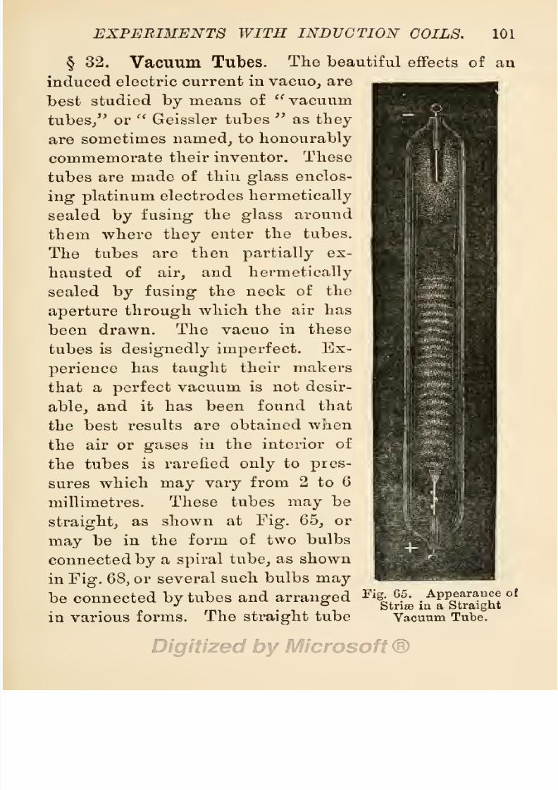
8/20/2019 electrical experiment.pdf
http://slidepdf.com/reader/full/electrical-experimentpdf 119/325
EXPERIMENTS
WITH
INDUCTION
COILS.
101
§
32.
Vacuum
Tubes.
The
beautiful
effects of
an
induced
electric
current
in
vacuo,
are
best
studied
by
means
of
vacuum
tubes,
or
Geissler
tubes
as
they
are
sometimes
named,
to
honourably
commemorate
their
inventor.
These
tubes
are
made of
thin
glass
enclos-
ing platinum
electrodes
hermetically
sealed
by
fusing
the
glass
around
them
where
they
enter
the tubes.
The
tubes
are
then
partially
ex-
hausted
of
air,
and
hermetically
sealed
by
fusing
the
neck
of
the
aperture
through
which
the
air
has
been
drawn.
The vacuo
in
these
tubes
is
designedly
imperfect.
Ex-
perience
has
taught
their
makers
that a
perfect
vacuum
is not desir-
able,
and it has
been found
that
the
best results
are obtained
when
the
air or
gases
in the interior
of
the tubes
is rarefied
only
to
pres-
sures which
may
vary
from
2
to
6
millimetres.
These
tubes
may
be
straight,
as
shown
at
Fig.
65,
or
may
be
in
the
form
of
two bulbs
connected
by
a
spiral
tube,
as shown
in
Fig.
68,
or several
such
bulbs
may
be
connected
by
tubes
and
arranged
F
'%^.^3
of
in various
forms.
The
straight
tube
Strife
in
a
Straight
Vacuum
Tube.

8/20/2019 electrical experiment.pdf
http://slidepdf.com/reader/full/electrical-experimentpdf 120/325
102
ELECTRICAL EXPERIMENTS.
may
also
form an outer
casing
or
protection
to
a
great
variety
of devices
in
bent-glass
tubing,
sucli as
letters,
architectural
designs,
figures
of
men,
animals,
birds, etc.,
some
of
which
are
shown
in
the
annexed
figures.
A
still further
variety
may
be secured
by
employing
stained
glass,
such
as
uranium
glass,
in
making
the
tubes.
Beautiful
effects
may
be obtained
from rarefied
gases,
and
vapours
of
volatile
liquids
hermetically
sealed
Fig.
66.
Various
Forms
of
Vacuum
Tubes.
in
Geissler
tubes.
For
instance,
a
tube
containing
rarefied
nitrogen
will
show
a
brush of
red or
rose-
tinted
light
at the
positive
electrode,
and
a
light-blue
or
violet
halo around
the
negative
electrode.
With
hydrogen
the
brush
is
crimson and
the
halo
blue.
With
carbonic
acid
gas
the
brush
is
green
arranged
in
rings
or
discs,
and
the
glow
a
pretty
lavender
blue in

8/20/2019 electrical experiment.pdf
http://slidepdf.com/reader/full/electrical-experimentpdf 121/325
EXPERIMENTS
WITH
INDUCTION
COILS.
103
bright
layers.
If
a
tube
with
contracted
middle,
as
shown
in
Fig.
G7,
is
employ
ed,
the
colours
will
be
brighter
in
the nar-
row
part
of
the
tube,
and
this
form
may
be
utilised
for
illustrations in
spectrum analysis.
Another
series
of
tubes
may
be
prepared
with
hollow bulbs
connected
by
short
thin
pipes,
the
bulbs
containing
mercury, powdered
calcium,
or
some
other
substances,
which
are
made
phosphorescent
by
the
action
of
the
induced
current
and emit
brilliant
colours
after
the current
has
ceased.
A
full
set
of such
Geissler tubes
would
be
worth
several
pounds,
the
most intricate
costing
as
much
as
two
guineas
each,
but the
simpler
forms
may
be obtained
from
opti-
cians
and
dealers
in
electrical
goods
at
low
prices,
from Is. Qd. each
up-
ward,
according
to
size
and
design.
As a
guide
to
intending
pur-
chasers,
I herewith
append
descrip-
tions of
some
forms
of Gassiot
tubes
and
the
results obtainable
from
them.
Compound
Tabes.
These
are small
vacuum
tubes
enclosed
in
an
outer
Fi
s-
67.
Appearance
of
,
,
.
.
p
,
.
, ,
,
Strire
in a
Contracted
sheathing
or
glass,
the
space
between
Vacuum Tube.

8/20/2019 electrical experiment.pdf
http://slidepdf.com/reader/full/electrical-experimentpdf 122/325
104
ELECTRICAL EXPERIMENTS.
the
two tubes
being
filled with a
fluorescent
solution
such as
sulphate
of
quinine,
which
imparts
a beautiful
coloured
margin
to the stream of
light
passing
through
the
inner
tube.
Convoluted
Tubes.
These
resemble
the
compound
tubes
in
their
construction,
the
sole difference
being
in
the
form of
the
outer
casing,
and
the
convoluted
tube
<£>3^v^^
Fig.
68.
Various
Forms
of Vacuum
Tubes.
enclosed
in
it.
The
convoluted
tube
ends
in
two bulbs
each
fitted
with
platinum
wires,
and the outer
casing
is
shaped
to suit
the
form
of
the
convoluted
tube.
The
space
in
the outer
casing
around
the
inner
tube
and
between
the terminal
bulbs,
is
filled
with
a
fluorescent
solution.
The inner
tube
is
sometimes
made
of
tinted
glass,
and
wrought
into
such
forms
as
that of a
cross,
a
crown,
a star
5
or
figure
of
flower
or
animal.
In
some,
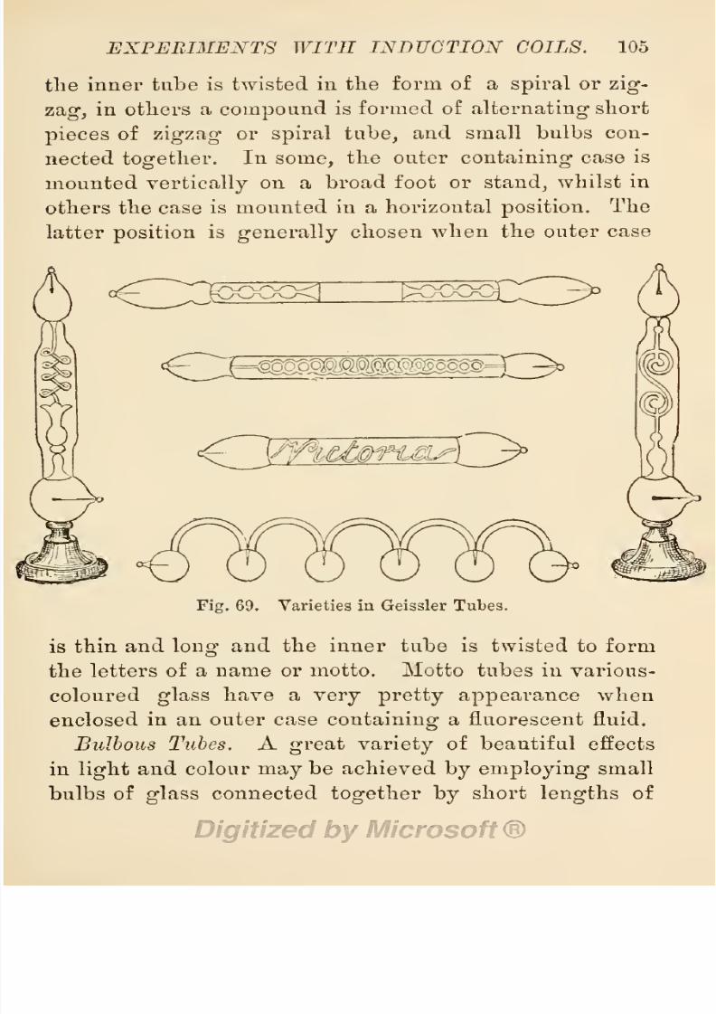
8/20/2019 electrical experiment.pdf
http://slidepdf.com/reader/full/electrical-experimentpdf 123/325
EXPERIMENTS
WIT
II
INDUCTION COILS.
105
the
inner
tube
is
twisted
in
the
form of
a
spiral
or
zig-
zag,
in
others
a
compound
is
formed
of
alternating
short
pieces
of
zigzag
or
spiral
tube,
and
small
bulbs
con-
nected
together.
In
some,
the
outer
containing
case
is
mounted
vertically
on a broad
foot
or
stand,
whilst
in
others
the case
is
mounted
in
a horizontal
position.
The
latter
position
is
generally
chosen
when the
outer
case
OE
^fe
O
Fig.
69.
Varieties in Geissler Tubes.
is thin
and
long
and
the
inner
tube
is twisted
to form
the
letters
of
a
name
or
motto. Motto tubes
in
various-
coloured
glass
have
a
very pretty appearance
when
enclosed
in
an
outer
case
containing
a
fluorescent
fluid.
Bulbous Tubes.
A
great
variety
of beautiful
effects
in
light
and
colour
may
be
achieved
by
employing
small
bulbs
of
glass
connected
together by
short
lengths
of

8/20/2019 electrical experiment.pdf
http://slidepdf.com/reader/full/electrical-experimentpdf 124/325
106
ELECTRICAL EXPERIMENTS.
small
glass
tube,
curved
to
form various
figures
such
as
a
simple
circle,
a
concentric
circle,
a
convolution
of
bulbs,
a
triangle,
a
pagoda,
or
a
helix.
Several
bulbs
may
be
&
D0LL0ND
Fig.
70.
Ornamental
Gassiot
Tubes on
Stands.
connected
in
a
row with
U-tubes,
and
others
with
twisted
tubes,
in fact an
almost
endless
variety
of
shapes
are
brought
into
requisition by
the
artistic
glass-blower.
The Care
of
Gassiot Tubes.
It
will
be
easily
under-

8/20/2019 electrical experiment.pdf
http://slidepdf.com/reader/full/electrical-experimentpdf 125/325
EXPERIMENTS WITH
INDUCTION
COILS.
107
stood
that such
fragile
articles
as
thin
glass
tubes
twisted
into
a
variety
of
forms,
will
need
great
care
to
protect
them
from
injury.
They
are
usually
sold
and
kept
in boxes
packed
with
cotton
wool,
to
which
they
should be
consigned
at
once
after
each
experiment.
A
very
small
coil,
giving
only
|-inch
spark,
will
produce
luminous
effects in
tubes
from
6
inches
to
12
inches
in
length,
but
these
will
not
be
the
best
obtainable from
such
tubes.
Tubes of
3
inches in
length
may
be used
for
coils
giving
£
to
|-mch.
sparks,
but
such small
tubes
should
not
be
put
on
to
large
coils
giving
sparks
of
1 inch and
over
this
length,
unless
the
platinum
wires
are
very
stout.
Tubes
of 6
inches
or
more,
or
long
convoluted tubes
may
be
worked
with
larger
coils
;
but
no
definite
rule
can
be
laid
down
to
guide
us in
adapt-
ing
the
length
of
tube
to
the
size
of
coil,
unless it bo
that
of
the
safe
carrying
capacity
of
the
platinum
wires
at
the
ends
of
the
tubes. If
these
get
hot,
the
tube
should be
at
once
disconnected.
If
this
is
not
done,
a
portion
of
the
wire
will
be
volatilised,
and
the
inside of
the tube
coated
with
deposited platinum,
or
the
wires
may
be
fused.
It
should
be
understood
also
that
the
thin wires
fused
into
those
tubes
will
not stand
a
very
great
strain
upon
them,
and
therefore should
not be
much
bent or
twisted.
Should
the
outside
loop
be
broken
off,
the
tube
is
not
entirely
useless,
although
its
usefulness
is
much
impaired.
It
may
still
be
used
in
experiments
where a
metal
contact can
be
pressed
against
the
ends
of
the
tube,
and
in
experiments
with
a
Winter
or
Wimshurst
electric
machine.
8/20/2019 electrical experiment.pdf
http://slidepdf.com/reader/full/electrical-experimentpdf 126/325
108
E
LEGTRIG
AL
EXPERIMENTS.
§
33.
Tesla's
Experiments
with
Vacuum
Tubes.
During
the winter
of
1891-2,
Mr.
Tesla astonished
a
large
number
of
persons
in
this
aud
other
countries
by
a
series
of
bold
experiments
with
high-tension
currents
of
electricity, among
these
being
one
with a
vacuum
tube
illuminated
by
a
very
high-tension
current
passed
through
his
own
body.
Not
a
few electricians
and
scientists were
betrayed
into
utterances
of
astonishment,
and
some
space
was
taken
up
in
scientific
journals
in
discussing
the wonderful
discovery.
As
the current
experimented
with was obtained
from
an
alternating
dynamo,
it was
argued
that
the
secret
lay
in
the
fre-
quency
of alternations
of
the
current,
and
only
those
with
a
high
frequency
could
be
so
used. The
ordinary
newspapers
and
quasi-scientific
journals
of
the
day,
were,
as
usual,
intoxicated
with
the
apparent
marvellous
discovery,
one
going
so
far
as
to
predict
that
It
seems
that
the
light
of the
future
will
be
a
soft
phosphorescent
glow,
the
colour
of
which
may
be
arranged
to suit
any
taste.
Our rooms
will
be
electrical fields
of
rapidly
alternating
electrical
stress,
in
which,
though
nothing
is
sensible
to the
occupant,
vacuum
tubes
and
phos-
phorescent
globes
will
shed their
light
wherever
they
may
be
placed,
no
connecting
wires or
any
attention
being
necessary.
Without
attempting
to
depreciate
the beautiful
results of
the
experiments
performed by
Mr.
Tesla,
I
must,
however, point
out
that
they
are
not
in
any
way
original,
nor
can
he
claim
to be
their
discoverer.
They
are
as
old
as
the
experiments
per-
formed
by
Gassiot
and
Giessler
with
vacuum
tubes,
and

8/20/2019 electrical experiment.pdf
http://slidepdf.com/reader/full/electrical-experimentpdf 127/325
EXPERIMENTS
WITH
INDUCTION
COILS.
109
may
be
repeated
by
any
person
having
a
spark
coil
and
a
few vacuum tubes.
The
experiment
may
be
per-
formed
easily
with
a
£-inch
spark
coil
and
a
short
vacuum
tube.
Put
the
coil on
a
table,
and set
it in
action
discharging
sparks
in
the
usual manner
by
tho
aid
of
dischargers
across
^-inch
of
space.
Take
the
vacuum
tube
in one
hand and
with it
touch
the
positive
discharger
rod,
then with
the
other
hand
point
to
the
other
discharger.
A
portion
of
the
induced
current
will
pass through
the
tube,
illuminating
it in
the
usual
manner,
and
return
to
the
coil
by
the
finger
of
the
opposite
hand.
That
this
current
passes
through
the
body
of the
operator
can be
easily
demonstrated
by
swaying
the
body
nearer to
the coil
or
farther
away
from
it.
When the
disengaged
hand
is
brought
near
the
negative discharger,
a decided
shock
is felt in
the
arms,
and
the
light
in
the
tube
glows
brighter.
When
the hand
is
drawn
back,
the
light
becomes
fainter
be-
cause
of
the
increased
resistance
of the
circuit
due to
air
space.
From
a
|-inch
spark
coil over
12,000
volts
will
pass through
the
operator's
body,
and with
an
inch
spark
coil
the enormous
tension
of
50,000
volts can
bo
borne
with
ease,
providing,
of
course,
that the
dis-
engaged
hand
is
not
placed
in
contact
with
the
coil
or
any part
of
the
apparatus.
If
the
resistance
of
the
circuit
is
kept high
enough
to
only
allow
2
milliamperes
of
current
to
pass
through
the
body,
most
brilliant
effects
can
be thus obtained
from
vacuum
tubes without
danger
to
the
operator.
It
will
thus
be seen
that the
results
obtained do not
depend
upon
the
frequency
of
8/20/2019 electrical experiment.pdf
http://slidepdf.com/reader/full/electrical-experimentpdf 128/325
110
ELECTRICAL
EXPERIMENTS.
the alternations
in the
current,
since
the
contact
breaker
may
work
fast
or
slow,
and
yet
the
experiment
prove
a
success.
The
experiment
may
also be
tried
with
in-
candescent
electric
lamps.
It is
only
necessary
to
con-
nect one
terminal
of
the
lamp
to the
positive
discharger,
and
hold
the
lamp
in one
hand
whilst
the
other
is
pointed
to the
coil.
Or the
lamp
may
be
suspended
between
the
terminals
of
the
coil,
with
equally
good
results.
Lamps
with
broken
filaments
will
do
as well
as or
better
than
good
lamps.
Beautiful
effects
may
be
produced
by
using
lamps
with
patches
of
tinfoil
pasted
on
their sides.
§
34.
Rotating
Vacuum
Tubes.
A
very
pretty
ex-
periment
with
vacuum
tubes
may
be
performed
by
rotating
one
of
them
at
a
high
rate
of
speed
whilst
the
induced
current
from
a
coil
is
passing
through
the
tube.
The
streak
of
light
is
then
multiplied
into
several
rays,
and takes
the form
of
a
star,
from
which
appearance,
and
the
fact
that
its invention
has
been
credited
to
M.
Gassiot,
it has
been named
a
Gassiot
Star.
It
will
be
readily
understood
that the
rotating
apparatus
must
be
specially
constructed
to
meet the
combined
requirements
of
tube
holder
and
rotator,
and
maintain
electric
connection
with
the
coil.
The
first
may
be
easily
met
by
the
employment
of
suitable
metal
clips
to
clutch and
hold
the
tubes,
and the
second
by
a
wheel
or
vertical
arm
attached
to
a pulley
made
to
revolve
at
a
high
rate
of
speed
by
means of
suitable
wheels
and
bands.
The
third
requirement
is met
by
mounting
two
metal
rings
on the
wooden
hub
of the

8/20/2019 electrical experiment.pdf
http://slidepdf.com/reader/full/electrical-experimentpdf 129/325
EXPERIMENTS
WITH
INDUCTION
COILS.
Ill
rotating
wheel,
and
allowing
two metal
springs
to
press
against
these. The
fixed
springs
are
connected
to
the
coil,
and the
revolving
rings
are connected
by
wires
to
the
clips
which hold
the
ends
of
the tubes.
Thus
the
two
ends
of
the
tubes
are connected
through
the
metal
rings
of the hub
of
the
rotator,
with
the
metal
springs
pressing
against
them,
and these are connected with
the
coil.
Fig.
71.
Gassiot
Star
Hand
Rotator.
The
tubes
may
be
rotated
by
hand
or
by
means
of
a
small
electro-motor. The
latter
method
is
most
popular,
and
to
be
highly
recommended
because
it
calls into
play
an interest
in a
useful
electrical machine.
Almost
any
form of
electro-motor
may
be
employed
for this
purpose.
The
tubes must
be
mounted on
a stand of
sufficient
height
to
allow
of their
free
rotation,
and
this
stand must be
so
constructed as
to
allow
of the tubes
being
rotated
whilst
they
are
in
circuit with
the
coil.
Power
may
be
conveyed
from
the
motor
to
the
rotator,
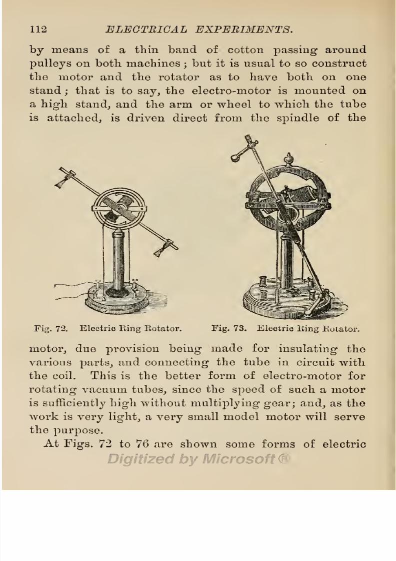
8/20/2019 electrical experiment.pdf
http://slidepdf.com/reader/full/electrical-experimentpdf 130/325
112
ELECTRICAL
EXPERIMENTS.
by
means
of
a tliin
band of cotton
passing
around
pulleys
on both machines
;
but it
is
usual
to
so
construct
the
motor
and
the
rotator
as to
have
both
on one
stand
;
that
is to
say,
the electro-motor is
mounted
on
a
high
stand,
and
the arm
or
wheel
to
which
the
tube
is
attached,
is
driven
direct
from the
spindle
of the
Fig.
72.
Electric
Eing
Kotator.
Fig.
73. Electric
liing
Kulator.
motor,
due
provision
being
made
for
insulating
the
various
parts,
and
connecting
the tube in
circuit with
the
coil. This is
the
better
form
of
electro-motor
for
rotating
vacuum
tubes,
since
the
speed
of
such
a
motor
is
sufficiently
high
without
multiplying
gear;
and,
as
the
work
is
very
light,
a
very
small
model
motor
will
serve
the
purpose.
At
Figs.
72
to
76
are shown some
forms of electric

8/20/2019 electrical experiment.pdf
http://slidepdf.com/reader/full/electrical-experimentpdf 131/325
EXPERIMENTS WITH
INDUCTION
COILS.
113
rotators.
Figs.
72 and
73
show a
form
usually
sold
by
opticians
at
prices
varying-
from £1
Is.
to
25s.
In
this
form
there
are two
bobbins with iron
cores
wound
with
insulated
copper
wire,
mounted
on
a
spindle carrying
the
commutator and
a
pair
of
arms
to hold the vacuum
tube. These bobbins
are free to
revolve inside an iron
ring
cut
into
steps
as shown
in
the
sketch,
the
cores
of
the
bobbins
being
attracted
to
the
steps
when the
Fig.
74.
Electric Eotator
with
Crank
Motion.
circuit
is closed. This
form has
been
improved by
Mr.
H.
Dale,
who
has
arranged
the
working
parts
so as to
have the
electro-magnets
fixed,
and
the
iron
ring
to
move
around
them.
At
Fig.
74
is
shown
an
electric
rotator
with crank
motion
worked
by
a
lever
attached
to
the
movable armature
of
an
electro-magnet.
This is
sold
for
18s.
Qd.
Any
small
two-pole
electro-motor
may
be
employed
for the
purpose
of
rotating
vacuum tubes
if
mounted
i

8/20/2019 electrical experiment.pdf
http://slidepdf.com/reader/full/electrical-experimentpdf 132/325
114
ELECTRICAL
EXPERIMENTS.
on
a
pedestal
high
enough
to
allow
a
free
play
in the
carrying
arms. Mr. G.
Bowron
has
mounted
a small
motor
of
the
type
manufactured
by
him,
on
a
pedestal
in this
way,
as
shown
at
Fig.
75,
and claims
that
it
is
superior
to the
ordinary
forms of
electric
rotation.
It
may
be
employed
to rotate vacuum
tubes,
or
by
un-
screwing
the
carrier
and
substituting
the
arms
of
a
Fig.
75.
Bowron's
Electric
Ilotator.
light
fan,
it
may
be
used
to
promote
the
circulation of
air
in
a
room
on a
hot
day.
The
price
of
this
motor is
£1
Is.
without
the
fan,
or
combined
with
the
fan,
£1
7s.
6d.
Messrs.
King,
Mendham
&
Co.
sell
a
small
motor
of
this
type,
manufactured
by
them
for
a
similar
purpose.
This
can
be altered
to
serve
the
purpose
of
a
vacuum
tube
rotator,
and
may
be
worked
by
current

8/20/2019 electrical experiment.pdf
http://slidepdf.com/reader/full/electrical-experimentpdf 133/325
EXPERIMENTS
WITH
INDUCTION
COILS.
115
from
three cells
of
a
Hellesen
or
other
dry battery.
The
price
is
£1 10s.
Those
of
my
readers
who
may
wish
to
make
a
small
electro-motor
for
themselves
will
find
ample
illustrated
instructions
to
guide
them in
Electro-Motors
: How
Made
and
How
Used,
a
handbook on
the
subject
by
Mr.
S.
R.
Bottone,
published
by
Whittaker
& Co.
Fig.
76.
King,
Mendham
&
Co.'s
Electric
Fan.
§
35.
Other
Experiments
with Vacuum
Tubes.
The few
experiments
described
in
previous
sections
do
not
cover the
whole
ground
of
interesting
experi-
ments
possible
with
the
induction
coil
and
vacuum
tubes. Some
of these
possibilities
are shown
in
a
series
of
three
articles
(profusely
illustrated)
which
appeared
in the
Electrician,
vol.
xxvi.
pp.
323,
354,
389,
under
the
title
of
Electricity
in
Transitu :
From Plenum
to
Vacuum;
being
the
substance of
a
presidential
address

8/20/2019 electrical experiment.pdf
http://slidepdf.com/reader/full/electrical-experimentpdf 134/325
116
ELECTRIC
AL
EXPERIMENTS.
by
Professor
William
Crookes,
F.R.S.,
at
a
meeting
of
the
Institution
of
Electrical
Engineers.
The student
may
also
find
an
illustrated
descrip-
tion of
experiments
with
vacuum tubes
in
Elec-
tricity
in
the Service
of
Man,
pp.
198-212,
a
book
published
by
Messrs.
Cas-
sell &
Co.
A beautiful
experiment
showing
the
effect
of
permanent
mag-
nets on the
striee
in
vacuum
tubes,
taken
from
this
source,
is shown at
Fig.
77.
Prof.
J.
J. Thomson
has
obtained an electric
dis-
charge through
rarefied
gases
without
the
use
of
electrodes.
A
vacuum
tube
containing
a
rarefied
gas
had
a
long
glass
tube
(con-
taining
a
thread
of
mer-
cury)
coiled
four
times
along
it,
and
the
discharge
from
a
number
of
Leyden
jars
was sent
through
this
thread.
An
induced
discharge
was
caused
in
the
vacuum
tube
near
the
line of
the
primary
discharge,
s
H
a
p
o
e3
>
a
-t-3
CD
o
CD
a
to
S3
CD
a
a
a
<D
0<
a
to

8/20/2019 electrical experiment.pdf
http://slidepdf.com/reader/full/electrical-experimentpdf 135/325
EXPERIMENTS
WITH
INDUCTION
COILS.
117
and this
did not
show
strise
as
in
the
ordinary
vacuum
tube
experiments.
§
36.
Physiological
Effects from
Induction
Coils.
The current delivered
from
the
terminals of
a
1-inch
spark
induction
coil has an
E.M.F.
of
50,000
volts.
That
from a
^-inch
spark
coil
will be
25,000
volts;
from
a ^-inch
spark
coil
12,500
volts
;
and
even
from
an
i-inch
spark
coil
over
6,000
volts
pressure
may
be
obtained.
If
this
discharge
of
high-tension
electricity
is
sent
through
living
animal
tissues,
such as
the
muscles
and nerves
of
the human
body,
it
causes
a
violent
and
painful
contraction and relaxation
of
the
tissues.
These
effects
are
very injurious
to
nervously
sensitive
persons,
who
may
be most
seriously
injured
by
shocks from even
a ^-inch
spark
coil. Care must
therefore be taken
to
guard any part
of
the
body
from
such
shocks,
by
avoiding
an inclusion of
the
operator
in
the
secondary
circuit.
It is
best
to
switch
the
coil
out
of action whilst
altering,
adjusting,
or
connecting
any
apparatus
attached
to
the
terminals
of
the
secondary
coil.
If
this
cannot
be
done,
the
alteration
must
be
made with one
hand
only.
Whilst
performing
experi-
ments
with the
coil,
no
second
person
(except
an
assistant)
should
be
allowed to
handle
any
of the
apparatus,
or touch
any
part
of
the
secondary
circuit,
so
as
to
avoid
the risk of
injurious
shocks.
The
practice
of
administering
shocks
from
coils
to
uninitiated
persons
for the
purpose
of
amusement is
strongly
to be
deprecated,
unless
performed
with an
£-inch
spark
coil,
under conditions
made to
prevent
the full

8/20/2019 electrical experiment.pdf
http://slidepdf.com/reader/full/electrical-experimentpdf 136/325
118
ELECTRICAL
EXPERIMENTS.
force
of
the
current
being
sent
through
the
body.
The
baneful
physiological
effects
of
an
electric
current
on
human
beings
depends
entirely
on
the
volume
of
current
sent
through
the
body.
Almost
any
person
can
bear
a
current
volume
of
two
milliamperes,
that
is
a
two-thousandth
part
of
an
ampere
j
and
if
the
re-
sistances
in
circuit
are
sufficient
to
only
allow
this
volume
of
current
to
pass
through
the
body,
no
appre-
hension
or
fear
may
be
entertained
as
to
the
result.
For
instance,
if a
person's
whole
body,
having
a
resist-
ance
of
4,000
ohms,
is
placed
in
the
secondary
circuit
of
an
i-inch
spark
coil,
together
with
a
high-water
resistance
of
say
some
10,000
ohms
or
over,
such as
that
which
obtains
in the coin
and
water
experiment,
little
or
no
bad
effects
may
be
feared,
although
a
smart
shock
may
be
felt
on
touching
the
water.
This
experiment
occasions
not a
little
amusement
in
a
company
of
young
persons.
Place
a
silver
coin
in
a
basin
of
water,
and
dip
a conductor
from
one
of
the
terminals
of
the
secondary
coil
into
the
water.
A
piece
of
brass
clock
chain
or
a metal
Albert
chain,
connected
to
the
end
of
a
long
piece
of
insulated
copper
wire,
will
serve
the
purpose
of
a conductor.
The
other
terminal
of
the
coil
must be
connected
to
a
metal
plate
or
other
conductor,
so
situated
as to be
trod
upon
by
any person
attempting
to
take
the
coin
from
the
basin.
When
the
coil
is
in
action,
a smart
shock
will
be
given
to
the
fingers
of
any
person
attempting
to
take
the
coin
from
the
water.
Some
owners
of
coils
find
a
great
deal of
pleasure
in
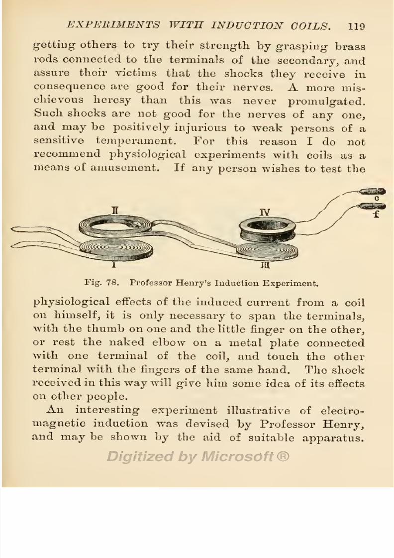
8/20/2019 electrical experiment.pdf
http://slidepdf.com/reader/full/electrical-experimentpdf 137/325
EXPERIMENTS WITH
INDUCTION
COILS. 119
getting
others
to
try
their
strength
by
grasping
brass
rods
connected to
the
terminals
of
the
secondary,
and
assure
their
victims
that
the
shocks
they
receive in
consequence
are
good
for
their
nerves.
A
more
mis-
chievous
heresy
than
this
was
never
promulgated.
Such
shocks
are
not
good
for
the
nerves
of
any
one,
and
may
be
positively
injurious
to
weak
persons
of
a
sensitive
temperament.
For
this
reason I
do
not
recommend
physiological
experiments
with
coils
as
a
means of
amusement.
If
any
person
wishes
to test
the
Fig.
78.
Professor
Henry's
Induction
Experiment.
physiological
effects of
the
induced
current from
a
coil
on
himself,
it
is
only
necessary
to
span
the
terminals,
with
the
thumb
on
one
and
the little
finger
on
the
other,
or
rest
the
naked
elbow
on
a
metal
plate
connected
with
one
terminal of
the
coil,
and
touch
the other
terminal
with the
fingers
of
the
same
hand. The shock
received
in
this
way
will
give
him
some
idea
of
its
effects
on
other
people.
An
interesting
experiment
illustrative of
electro-
magnetic
induction was
devised
by
Professor
Henry,
and
may
be shown
by
the
aid
of
suitable
apparatus.
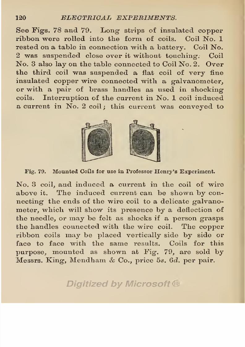
8/20/2019 electrical experiment.pdf
http://slidepdf.com/reader/full/electrical-experimentpdf 138/325
120
ELECTRICAL EXPERIMENTS.
See
Figs.
78
and
79.
Long
strips
of
insulated
copper
ribbon were rolled into
the form
of
coils.
Coil
No.
1
rested
on a
table
in
connection
with
a
battery.
Coil No.
2
was
suspended
close
over
it
without
touching.
Coil
No.
3
also
lay
on
the
table
connected to Coil No. 2.
Over
the
third
coil was
suspended
a flat coil of
very
fine
insulated
copper
wire
connected
with
a
galvanometer,
or
with
a
pair
of
brass
handles as
used
in
shocking
coils.
Interruption
of
the
current
in
No.
1 coil
induced
a
current
in No. 2
coil;
this
current was
conveyed
to
Fig.
79.
Mounted
Coils
for
use
in
Professor
Henry's Experiment.
No.
3
coil,
and
induced
a current in
the coil
of
wire
above
it.
The
induced
current
can be
shown
by
con-
necting
the
ends
of
the
wire
coil
to
a
delicate
galvano-
meter,
which will show
its
presence
by
a deflection
of
the
needle,
or
may
be
felt
as
shocks
if
a
person
grasps
the
handles connected
with
the wire
coil. The
copper
ribbon
coils
may
be
placed
vertically
side
by
side
or
face
to
face with the same
results.
Coils for
this
purpose,
mounted
as
shown
at
Fig.
79,
are sold
by
Messrs.
King,
Mendham
&
Co.,
price
5s.
6d.
per
pair.

8/20/2019 electrical experiment.pdf
http://slidepdf.com/reader/full/electrical-experimentpdf 139/325
CHAPTER
IV.
EXPERIMENTS WITH
STATIC
ELECTRICITY.
§
37.
The
Production
of
Static
Electricity.
Al-
though
very
rapid
strides have
been
made
during
the
last
quarter
of
a
century
in
our
knowledge
of
the
natural
force
known
to
us under
the name
of
electricity,
this
acquisition
of
knowledge
has
only
served to
show
the
best
of its
students
the extent
of their
ignorance
respecting
its
nature.
We
are
still
floundering
in
a
flood
of
unanswered
questions
surrounding
the
central
one
—
Electricity
: What
is
it
?
Hence,
although
ad-
vanced
thinkers
readily
concede
that
the
force,
in
what-
ever
form
it is found
or
however
produced,
is
always
the same
thing,
many
of
them
still
cling
to terms
which
indicate
a
state
of
ignorance
when
men
thought
of
electricity
as a
fluid,
or
several
fluids
of like
character,
to
which
the
names of
positive,
negative,
voltaic,
or
static
were
given.
The
close relation
of
magnetism
to
electricity
has
already
been shown
in
previous
sections
by
means
of
experiments.
It
has
been
shown
that
the
permanent
magnetic
condition
induced
in
a
piece
of
hard steel
by
rubbing
it
with
another
magnet,
or
by
sending
a
current
of
electricity
through
a
wire
wound over
the
steel,
is
121

8/20/2019 electrical experiment.pdf
http://slidepdf.com/reader/full/electrical-experimentpdf 140/325
122
ELECTRICAL
EXPERIMENTS.
identical with an
electric
current
passing
through
a
copper
wire,
both
having polar
extremities
and
behaving
alike
under certain conditions.
In
the
experiments
about
to
be
described,
a
similar
condition
will be
ob-
served
in
the
materials
charged
with
static
electricity,
this term
being
chosen to
indicate
the
magnetic
con-
dition
of
bodies other
than
steel.
It
will
be
seen
that
they
behave much the
same
as
permanent
magnets,
in
that
they
have
polar
extremities,
with
the
known
mag-
netic
properties, answering
to
the
laws
of
like
poles
repelling
and
unlike
poles
attracting
each
other,
but
that
they
differ
from
steel
magnets
in
only
retaining
the
magnetic
condition
for a
short
time,
and
a readiness
to
give
up
their
charge
to other
substances.
Static
electricity
is the
name
given
to
the
magnetic
condition
of
substances
after
they
have
been
rubbed
with
other substances
capable
of
inducing
a
magnetic
charge.
It is
named
static
because
electricity
is
sup-
posed
to
be
at
rest
in
those
charged
bodies,
but
the
term
bound
electricity
is also
applied
to
this
condition.
As
this
condition
is
induced
by
friction,
it
is
named
frictional
electricity.
It
is
produced
by
suitable
machines
and
apparatus
about to be
described.
§
38.
Simple
Producers
of
Electricity.
From
the
time
when
Thales rubbed a
piece
of
amber
with
silk,
and
found
that
it
then
possessed
the
power
of
at-
traction for
such
light
bodies
as feathers,
up
to
the
present
time,
this
attractive force
has been
known
under
the
name of
electricity,
a word
derived
from
electron,
the Greek
word
for
amber.
For
over
2,000

8/20/2019 electrical experiment.pdf
http://slidepdf.com/reader/full/electrical-experimentpdf 141/325
EXPERIMENTS
WITH
STATIC
ELECTRICITY. 123
years,
amber
was the
only
.substance
known
that
could
be used as
a
producer
of
electricity.
Toward
the end
of
the sixteenth
century,
Dr.
Gilbert,
a
physician
to
Queen
Elizabeth,
found
that
all
substances
could be
made
to
assume
an
electric
condition
if
properly
treated,
and
some
bodies,
such
as
sealing-wax,
shellac,
glass,
sulphur,
etc.,
could
be
made
to
easily
assume
a condi-
tion
nearly
resembling
magnetism.
If
a rod
of
sealing-
Fig.
80.
Experiment
to
prove
Attractive
Influence
of
an
Electrified Rod of
Sealing-Wax.
wax
be
briskly
rubbed
for a
few seconds
with
a
piece
of
silk,
or of
cloth,
or
the
sleeve
of
a
coat,
and
then
presented
to small
feathers,
or
small
pieces
of
silk,
wool,
paper,
and
gold
leaf,
or
bran,
or similar
light
sub-
stances,
the small
particles
will
spring
up
and
adhere
to
the
sealing-wax,
until
they
have
received
a
full
charge,
when
(obeying
the
law
of
magnetized
bodies,
of
like
repelling
like)
they
are
thrown off from
the
rod.
A
glass
rod,
a
rod of
ebonite,
a
cake
of
shellac,
a
lump

8/20/2019 electrical experiment.pdf
http://slidepdf.com/reader/full/electrical-experimentpdf 142/325
124
ELECTRICAL
EXPERIMENTS.
of
resin,
a roll
of
sulphur,
or
a
cake
of
wax
will
behave
in
a similar
manner,
when
rubbed with
dry
silk
or
with
dry
flannel,
or
a
piece
of
fur,
or
a
catskin.
Metals
can
be
made
to
receive
a
charge
if
they
are
insulated
from
the
hand
of
the
experimenter
by
glass,
ebonite,
or
a
similar
non-conductor. Substances
that
fail to receive
a
charge
when rubbed
with
one
material,
may
be
charged
when rubbed
by
some other
material.
A
very
interesting
experiment
to
a party
of
young
folks,
may
be
performed
with
a
piece
of
brown
paper,
whilst the
party
are
gathered
around
the
fire on
a
cold
winter's
evening.
On
warming
the
paper
at
the
fire
and
rubbing
it
briskly
for
a few
seconds
with the coat-
sleeve
or
a
piece
of
fur,
it
will
adhere
to
the
wall
paper
of
a
room
for
a
few
moments,
or
until
both
are
charged
alike.
Children will
try
this
with
varying
success,
and
a
corresponding
interest in the
experiment.
Another winter fireside
experiment
in
static
electricity
may
be
performed
on the domestic
cat
as
she
reclines
on
the
hearth-rug
in
front
of
the
fire.
Briskly
rub the
two
hands
together,
then
lightly
touch
the
fur
of
the
cat
with one
finger.
The
fur
will
be
seen
to
start,
and
the
animal's
skin will
twitch
as
if
she received
a
shock,
which is
probably
the
case.
By
stroking
the
finger lightly along
the
cat's
back,
her
fur
will
lie down
close
to the
skin
along
the stroked
line,
and
leave
a
well-defined
depression
in
the
fur.
On
briskly
stroking
the back of the cat
in
frosty
weather,
a
large quantity
of
electricity
may
be
produced,
of
sufficient
high
ten-
sion to cause
crackling
sparks,
which
are
plainly
visible

8/20/2019 electrical experiment.pdf
http://slidepdf.com/reader/full/electrical-experimentpdf 143/325
EXPERIMENTS
WITH
STATIC
ELECTRICITY.
125
in
the
darkened
room.
The
animal
suffers
some
dis-
comfort
on
drawing
sparks
from her
in
this
way,
and
unamiable
cats
are
liable
to
resent
such liberties.
The
same
evidence of
electricity
may
be
produced
on
the
fur
or
coat
of
other
animals,
but
not to the same
ex-
tent.
It
appears
to
be
more
pronounced
on
black
or
dark-coated animals
than
on
light-coated
ones.
A black
horse,
for
instance,
will
show streaks of electric
light
on
its
coat when
groomed
in
a
dark
stable,
or even
when
stroked with
the
fingers.
Animals
with
thick fur
or
hair
give
better
results than
those with short
coats.
§
39.
Indicators
of
Static
Electricity.
As we can-
not
proceed
very
far
in
our
experiments
with static
electricity
without
some means
at
our command
of as-
certaining
its
existence,
it
will
be
advisable
to notice
here
some
simple
apparatus
for
indicating
the
electric
condition of
substances
under
examination.
Instruments
for this
pui'pose
are named
electroscopes,
of
which
there are
several
varieties.
1.
Pith-Ball
Electroscopes.
It will
be seen on refer-
ring
to the
previous
section,
that
a
rod of
sealing-wax,
when
rubbed,
has
an
attractive
condition
imparted
to
it,
which
is
manifested
by
drawing
such
light particles
as
bits of
paper,
feathers,
etc.,
to
itself.
It
has
also
been
seen
that
these
light
particles only
remain
at-
tached
to
the
sealing-wax
for
a
short
time,
after which
they
are
thrown
off.
This
repulsive
action
follows as
a
consequence
of the
light
particles
being
charged
in
a
manner similar
to the
surface
of
the
sealing-wax,
when,
as like
conditions
repel
like,
the
similarly
charged

8/20/2019 electrical experiment.pdf
http://slidepdf.com/reader/full/electrical-experimentpdf 144/325
126
ELECTRICAL
EXPERIMENTS.
particles
are
repelled.
It has
been
found
that
the
dried
pith
of
plants
and
trees
may
be
attracted
or
re-
pelled
in like
manner,
and,
as
this
material
can be
easily
fashioned
into
little
balls,
it
has
been
selected
for
the
purpose
of
making
a
delicate
indicator
of
static
electricity.
As
the
pith
of
young
elder
shoots,
when
dry,
has
a
larger
diameter
than
that
of other
English
trees,
it
is
the
material
usually
selected
for the
purpose
of
making
pith
balls.
A
spherical
shape
is
selected,
because
rounded
surfaces
do
not so
readily
part
with
their
charge
of
electricity
as
angles
and
sharp
points.
Pith
may
be
easily
carved
to
any
shape
with
a
sharp
razor.
The
pith
balls
must be
suspended
by
single
filaments
of
cocoon
silk
to insulated
supports
of
glass
or
of
ebonite,
to
prevent
rapid
dissipation
of
electricity,
silk
and
glass
being
bad
conductors.
The
support
of
an
electroscope
may
be
a curved
piece
of
wire,
bent
to
the
form
of
a
hook
at
one
end,
and
cemented
at
the
other
end
into
a
glass
tube
to
form
a
pillar,
the
lower
end
of
which
is
cemented
into
a foot
or
stand
of
polished
hardwood,
as
shown
at
Fig.
84,
p.
181.
A
very
easy
and
most
inexpensive
method
of
making
these
instru-
ments
is
given
by
Mr.
Bottone
in
his
book
on
Electrical
Instrument
Making.
1
Pith-ball
electroscopes
are
made
in
three
forms.
1.
A
support
with one
pith
ball
only
suspended
to
the
insulated hook.
2.
A
support
with
two
pith
balls
suspended
side
by
side,
or
two
parallel
supports
with two
pith
balls
suspended
to
them.
3.
Two
pith
balls
balanced
on
the ends
of a straw
and
1
Published
by
Whittaker
&
Co.,
at 3s.

8/20/2019 electrical experiment.pdf
http://slidepdf.com/reader/full/electrical-experimentpdf 145/325
EXPERIMENTS
WITH
STATIC
ELECTRICITY,
127
secured to
a
tiny
glass
cup
turning
on
a
glass
pivot.
Directions for
making
these
are
given
in
the
book
above
mentioned.
2.
Gold-Leaf
Electroscopes.
Gold
leaf
is the
thin
material
used
by
sign-painters
and
book-binders
to
gild
letters,
and
is
sold
in
books for
this
purpose.
It is
so
light
and
fragile
as
to
be
easily
blown
away
by
a
light
puff
of
air,
or torn
by
a
stronger
blast,
and
is therefore
Pig.
81.
Goid-Leaf
Electroscope.
kept
between
the
leaves of
books.
This
light
material
will
readily
indicate
the faintest
trace
of
electricity,
if
suitably
disposed
and shielded
from
atmospheric
in-
fluences.
If
two thin
strips
of
gold
leaf are
suspended
inside
a
bottle
from
its
stopper,
and
a
substance
charged
with
electricity
is
brought
near
the
stopper,
the leaves
will
become
charged
and will
then
repel
each other.
A
wide-mouthed thin
glass
bottle
or
jar,
3
inches
in
8/20/2019 electrical experiment.pdf
http://slidepdf.com/reader/full/electrical-experimentpdf 146/325
128
ELECTRICAL
EXPERIMENTS.
diameter,
should
be selected
and
fitted
with
a
paraffined
hardwood
bung
through
which
passes
a brass
rod
termi-
nating
at
the
lower
end
by
a
clip
for
holding
the
gold-
leaf
strips
and at
the
other
end
by
a
brass
knob,
a
sharp
point,
or
a
brass
disc.
Two
strips
of
tinfoil
should
be
pasted
inside
the
jar
from
top
to
bottom,
or
two brass
pillars,
terminating
in
knobs,
be
fixed
in
the
stand at
the
bottom,
and the
jar
should
stand in
a metal
tray
to
facilitate
an
escape
of
the
electric
charge.
When
the
leaves
diverge
wide
enough
to touch
the tinfoil
strips
or the brass
pillars,
they
part
with
their
charge.
A
full
illustrated
description
of this
instrument,
together
with
concise
instructions
for
making
it
from
homely
materials,
is
given
in
Mr.
Bottone's
book,
Electrical
Instrument
Making,
pp.
14-20.
3.
Coulomb's
Torsion Balance.
The
electroscopes
pre-
viously
described
can
only
be
regarded
as indicators
of
the
presence
of
electricity
in
a
substance.
They
do not
show
the
strength
of electric
force.
With
Coulomb's
Torsion
Balance,
Fig.
82,
we
can
accurately
measure
the
strength
of
magnetic
and
electric force,
and demon-
strate the
laws of
electric attraction
and
repulsion.
By
the aid
of
this instrument
we
can
easily prove
that
electric
attractions
and
repulsions
are
inversely
as the
squares
of
the
distances,
and
directly
as the
charges.
The
construction
of
this
instrument is based on
the
well-known
fact
that
when
a
wire
is
twisted,
it
offers
a
resistance
to
the
strain,
and
returns
to
its
normal con-
dition when
the
twisting
or
lateral
strain
is
taken
off,
if
this
has not
been
excessive,
so
as
to
give
a
per-

8/20/2019 electrical experiment.pdf
http://slidepdf.com/reader/full/electrical-experimentpdf 147/325
EXPERIMENTS
WITH
STATIC
ELECTRICITY.
129
manent
twist
to the wire.
The
form
of
this
instrument
is
shown
at
Fig.
82,
from which
it will
be
seen
that
it
consists
of a
glass
case
enclosing
a
pointer
suspended
by
a
wire
from
the
top
of a central
glass
tube,
and an-
other
wire
(with
metal balls at both
ends)
near
the
side
of
the
case.
The
pointer
is
a
slender
rod
of
shellac,
carrying
at
one end
a small ball
of
brass or
of
copper,
«s»
Fig.
82.
Coulomb's
Torsion
Balance.
and
nicely
balanced
in
a
stirrup
at the
end of a
short
length
of
No.
40
German-silver
wire. The
upper
end
of this wire
is
soldered
to
a
brass
rod
terminating
in
a
brass ball
with an
index
pointer,
and
turning
freely
in
a
piece
of
brass
tube
cemented into the
cover
of
the
glass
tube.
The
side
of
the
case
is
graduated
with
E

8/20/2019 electrical experiment.pdf
http://slidepdf.com/reader/full/electrical-experimentpdf 148/325
130
ELEGTBIGAL
EXPERIMENTS.
marks
on
the
glass,
as shown
in
the
figure,
or
a
card-
board
disc
graduated
in
360
divisions
to
the
circle
is
fastened
to
the
base
of
the
instrument
under
the
pointer.
If
the
instrument
is
to
be
used
for
magnetic
experi-
ments,
the
light
shellac
rod is
replaced
by
a
light
steel
magnet.
The
price
of
such an
instrument,
as
given
in
Messrs.
King,
Mendham
&
Co.'s
list,
is
from £3
15s.
to
£5 5s.
Students
desirous
of
making
their
own
balance
from
homely
materials
at
a
low
cost,
will
find
full
illus-
trated
instructions in
Mr.
Bottone's
book,
Electrical
Instrument
Making,
pp.
20-23.
Fig.
83.
Henley's
Pith-Ball
Quadrant.
Among
many
other
forms
of
electroscopes,
I
may
mention Volta's
Condensing Electroscope,
described
and
illustrated
in
Ganot's
Physics,
§
769
;
Henley's
Pith-
ball
Quadrant,
illustrated at
Fig.
83,
and
sold
for
3s. 6d.
;
Cotterell's
Electroscope,
price
4s.
6d.
}
and
Lever's
Paper
Disc
Electroscope, price
10s.
6d.
There
are
also
several
other
forms of
electrometers besides
Coulomb's
Torsion
Balance,
among
the
most
important
being
Sir
Wm.
Thomson's
Electrometer,
and
his
absolute Electro-

8/20/2019 electrical experiment.pdf
http://slidepdf.com/reader/full/electrical-experimentpdf 149/325
EXPERIMENTS
WITH
STATIC
ELECTRICITY.
131
meter,
Lane's
Leyden
Jar
Electrometer,
and
Harris'
Unit Jar
Electrometer,
all
of which are
illustrated and
described
in
Ganot's
Physics/'
§
767
to
§
771.
§
40.
Experiments
with
Electroscopes.
Several
in-
teresting experiments
may
be
performed
with
electro-
scopes.
1.
Rub
a
stick
of
sealing-wax
with a
piece
of
flannel,
a
piece
of
cloth,
or
a
coat-sleeve,
and
present
it to
a
pith-ball
electroscope.
The
pith
ball
will
at
first
be
at-
Fig.
84.
Pith-Ball
Electroscope
and
Excited
Eod
of
Sealing-Wax.
tracted to the
sealing-wax,
when
it will
become
charged,
and will
then
be
at
once
repelled,
as
shown
in
Fig.
84.
Hold
the
opposite
end of the
sealing-wax
to
the
pith
ball.
No
effects
are
observable.
The unexcited
end
is
neutral.
Reasoning
from
an
analogy
between
this sub-
stance
and
a
piece
of
magnetized
steel,
the
opposite
end
should show
a
reverse
elective direction
to
that
which
attracted
the
pith
ball.
The
difference
in behaviour
is
caused
by
the bad
conducting property
of the seal-
8/20/2019 electrical experiment.pdf
http://slidepdf.com/reader/full/electrical-experimentpdf 150/325
132
ELECTRICAL
EXPERIMENTS.
ing-wax
as
compared
with that
of
steel.
Only
the
rubbed end of
the
sealing-wax
is
electrified.
The
experiment
may
be
repeated
on
the
gold-leaf
electro-
scope.
2.
Procure
a
glass
rod of
any
length
and
size,
but
preferentially,
for
convenience
in
handling,
from
5 to
6
inches
in
length,
and
\
to
f-inch
in
diameter.
Rub
this
with
a
piece
of
silk,
and
present
it to the
pith
ball.
The
ball
will
be
attracted
at
first,
and
then
repelled,
much
the
same as
when
presented
to
electi'ified
sealing-wax.
But,
now,
rub the rod of
sealing-wax
as
well as the
glass
rod,
and
present
them
alternately
to the
pith
ball.
The
repellent
action
of
one
will
be
reversed
by
the attractive
action
of
the
other.
That is
to
say,
whilst the
pith
ball
appears
to
swing
away
from
the
excited
glass
rod,
it
will
be
attracted to the
excited
sealing-wax.
This
shows
that
the
dh'ective
motion
of
the excited
particles
of
one
substance
is not the
same
in
both,
one
tending
to
move
in
one
direction,
whilst that
in
the
other
is
opposite.
This
experiment
led
Dufay
to observe
that
there
were two
kinds
of
electricities,
to
which
he
gave
the names
resinous,
when
obtained
from resinous
substances,
such as
sealing-wax,
shellac,
resin,
etc.
;
and
vitreous,
when obtained from
vitreous
substances,
such
as
glass.
Franklin
supposed
that
rubbing
the
substances
with
silk,
etc.,
developed
in
them
a
kind of
fluid,
and
this
became
either
positively
or
negatively
electrified,
the
rubbing
process
either
adding
to
or
taking
from
the fluid
some
of
its
properties.
This
theory
acquired
apparent
support
from the
fact
that

8/20/2019 electrical experiment.pdf
http://slidepdf.com/reader/full/electrical-experimentpdf 151/325
EXPERIMENTS
WITH
STATIC
ELECTRICITY.
133
glass
behaves
differently
when
rubbed
with
a
catskin
than
when
rubbed with
silk.
Symraer
assumed that all
substances
contained
bound
electricity
in
the
form
of
two fluids
united
together.
By
rubbing
the
substances,
these
two
fluids
were
separated,
one into
negative,
the
other
into
positive
electricity.
It
need
scarcely
be said
that
the fluid
theories of
these
respected
investigators,
are no
longer
held
by
electricians of
repute,
as
modern
research
has
failed to
discover
any
trace
of
a
fluid.
The
terms
' '
vitreous
and
'
'
resinous,
as
applied
to
electric
action
by
Dufay,
have
long
since
fallen into
disuse
;
but
the
terms
positive
and
negative,
invented
by
Franklin,
are still
retained
for
the
sake of
convenience
to
describe
two
opposite
conditions of
polarized
mole-
cular
matter,
positive
representing
the
condition
assumed
by
vitreous
substances
when
excited,
and
negative
representing
the
condition
of
the molecules
in
resinous
substances.
For
still
further
convenience,
by
way
of
abbreviation,
the
sign
(
+
)
has been
given
to
positive
conditions,
and
the
sign
(—
)
is
given
to
nega-
tive
conditions.
3.
Procure
a rod of
shellac,
and make for
one
end of
it
a
tiny
cap
of flannel
provided
with
a
thread of
silk.
Fit
the
cap
on
one end of the shellac
rod,
and
rub
it
around
the rod a
few
times,
then withdraw
the
cap
by
the
silken
thread,
and hold
it to
a
pith-ball pendulum.
The
ball
will
be
repelled,
thus
showing
that
it
is
posi-
tively
electrified
;
and,
if
the
shellac
rod is
presented
to
a
pith
ball,
it will
be
attracted,
thus
proving
that
both
conditions
exist,
one
in
the
rubber,
and
the
other
in
the

8/20/2019 electrical experiment.pdf
http://slidepdf.com/reader/full/electrical-experimentpdf 152/325
134
ELECTRICAL
EXPERIMENTS.
rubbed
substance.
A
rod
of
sealing-wax
may
be
used
in this
experiment
instead
of
a shellac
I'od,
if
desired.
The
experiment
should
also
be
tried
on
the
gold-leaf
electroscope.
4.
Procure
several
specimens
of
the
following
sub-
stances,
and
arrange
them
in the
order
given
below
:—
1.
Catskin.
6.
Cotton.
11.
Sealing-
Wax.
2.
Flannel.
7.
Silk.
12.
Resin.
3.
Ivory.
8.
Wood.
13.
Sulphur.
4.
Rock
Crystal.
9.
Copper.
14.
Gutta-Percha.
5.
Glass.
10.
India-Rubber.
15.
Gun-Cotton.
The
wood
(No.
8)
must
be
dry.
Other
metals
beside
copper
(No.
9) may
be
employed.
Ebonite
may
be
used
instead
of
or
with
india-rubber.
Shellac
may
be
used
instead
of
or
with
sealing-wax.
Vulcanite
may
be
used
instead
of or
with
gutta-percha.
Gun-paper
will
be
a
convenient
substitute
for
gun-cotton.
A
piece
of
leather
may
be
added
to
the
list,
and
a
blade of
copper,
or
of
brass
set
in a handle
of
ebonite,
will
be a
useful
acces-
sory.
Rub
the
catskin
and
flannel
together,
then
present
them
both to
separate
electric
pendulums.
One
will
attract
the
pith
ball,
whilst
the
other
will
repel
it.
Next
rub
the
piece
of
ivory
with
the
flannel,
and
present
both
to
the
pith
balls.
It
will
be
found
that
the
flannel
is
oppositely
excited
to
its
former
condition
when
rubbed
with
the
catskin,
and
oppositely
to
the
condition
of
the
ivory.
On
repeating
the
experiment
with
all the
rest
of
these
substances
in
order,
it will
be seen
that
each

8/20/2019 electrical experiment.pdf
http://slidepdf.com/reader/full/electrical-experimentpdf 153/325
EXPERIMENTS
WITH
STATIC
ELECTRICITY.
135
becomes
positively
excited
when
rubbed with
any
of the
substances
following
it in
the
list,
but
they
are
negatively
excited
by
rubbing
with
those
which
precede
it.
On
rubbing
the
naked
dry
hand
with
silk
or
any
of the
sub-
stances
preceding
it,
they
become
positively
excited;
but
if
any
of
the
substances lower
down
in
the
list
be
rubbed
with
the
hand,
they
will become
negatively
excited.
If
ebonite, vulcanite,
or
gun-paper
be
rubbed with leather
smeared with
electric
amalgam,
they
will become
posi-
tively
excited,
although
their
general
condition is
nega-
tive
when
rubbed
with other
substances.
If two
pieces
of
silk are
rubbed
together
across the
grain,
one will
become
positively,
and the
other,
negatively
excited.
If
two
pieces
of
metal,
or
of
wood,
or
of
any
other
sub-
stance,
are
rubbed
together,
the
piece
which
is
most
highly
polished
will
become
positively
excited,
whilst
the
rough specimen
will be
negatively
excited.
A
simi-
lar
effect
will
follow
if
the
substances
are of different
temperatures.
If
a
piece
of
cork and
a
piece
of
india-
rubber
be
pressed
together,
the
cork
will
become
posi-
tively
and
the
rubber
negatively
excited.
If
a
piece
of
metal
be
rubbed
with
any
other
substance,
the
electricity
will
escape by
the
hand and
body
almost as
rapidly
as
it
is
formed,
because
all metals are
good
conductors of
electricity;
but,
if
the
piece
of metal
be
held
in
an
insulating*
handle of
ebonite,
glass,
or
ivory,
so
as
to
prevent
rapid
dissipation
of
the
charge,
its
electrical
properties
may
be
investigated.
An electric condition
may
be
imparted
to the
brass knob of
a
gold-leaf
elec-
troscope
by flapping
it
with a
piece
of
catskin, far,
8/20/2019 electrical experiment.pdf
http://slidepdf.com/reader/full/electrical-experimentpdf 154/325
136
ELECTRICAL
EXPERIMENTS.
flannel,
or
silk,
and this condition
will
be
observed
by
divergence
of the
leaves.
5. With the
gold-leaf
electroscope
furnished
with
a
metal disc instead
of
a
knob on
top,
another series of
experiments
may
be
performed.
Take a
piece
of seal-
ing-wax
and
a rod
of
glass,
and rub both
with
a
silk
handkerchief. On
presenting
the excited
sealing-wax
to
the
disc,
the
leaves
of
the
electroscope
will
diverge,
but
they
will
approach
each
other
again
when
the
glass
rod is
presented,
thus
showing
that two
different
conditions exist
in
the two
materials.
A
similar result
will
follow from the
presentation
of
the
electrified
substances
previously
mentioned. Powder a little
dry
brimstone
in a
dry porcelain
mortar,
and
let
the
powder
fall
on
the
disc of
the
electroscope.
The
leaves
will
be
repelled.
Place
a
little
powdered
chalk
in
the nozzle
of
a
bellows,
and
blow
it
smartly
on
the
disc.
This
also
will
generate
enough electricity
to cause
divergence
of
the leaves.
Comb a bunch of
horse-hair
or
other
dry
hair,
and
present
it to
the
disc. Take
a
strip
of black
ribbon
and
a
strip
of
white
ribbon,
place
them
together,
and
draw
them
smartly
between the
fingers,
then
pre-
sent
them to
the
disc.
If this is
done
in
the
dark,
a
spark
will
pass
as the
ribbons
separate.
Rub
a sheet
of
dry
brown
paper
with
a
piece
of
india-rubber,
then
bring
this
carefully
and
gradually
near
the
disc.
The
leaves
will
be
powerfully
repelled,
and
may
be
ruptured
if
brought
too
near.
If
the
experiment
is
performed
in
a
darkened
room,
flashes
of
light
will be
given
off from
the
paper
as
it is
being
rubbed.
Freshly
ground
coffee,

8/20/2019 electrical experiment.pdf
http://slidepdf.com/reader/full/electrical-experimentpdf 155/325
EXPERIMENTS
WITH STATIC
ELECTRICITY.
137
freshly
cut
chips
of
wood,
and
freshly
torn
bombazine,
will
all excite
the
leaves
of
the
electroscope.
Rub
a
silk
glove
on
the
hand,
then
quickly
take
it
off
and
present
it to
the
electroscope.
On
touching
the
disc
with
the
finger
when the leaves
diverge,
they
will at
once
collapse,
because
they
give
up
their
positive
charge
to
the hand.
Stand
a
boy
on
an
insulating
stool,
Fig.
85,
or
on
a
board
resting
on
four
inverted
glass
tumblers,
and let
him
place
the
fingers
of
one
hand
lightly
on
the
brass
disc or
knob
of
the
electroscope.
No
effect
will be
Fig.
85.
Insulating
Stool.
observed
until he
is
flogged
with
a
silk
handkerchief,
a
piece
of
fur,
or
a
catskin,
when
the
leaves
will
diverge
and
show
that
electricity
has
been
generated
in
his coat
and
conducted
to
the
electroscope.
§
41.
The
Electrophorus.
Although
(as
shown
in
§
38)
charges
of
static
electricity
can be
given
to
simple
substances,
such
as
glass,
wax,
resin, shellac,
etc.,
by
merely
rubbing
them
with
silk
or with
wool,
the
charge
given
to
each
is
very
small,
because
their
capacity
for
charge
is also
small.
To
obtain
larger
charges
of
elec-
tricity
we
must
have
recourse
to some
apparatus
for
its
production.
One
of
the
most
simple
and
least
expensive

8/20/2019 electrical experiment.pdf
http://slidepdf.com/reader/full/electrical-experimentpdf 156/325
138
ELECTRICAL
EXPERIMENTS.
generators
of
static
electricity,
is
the
electrophorus,
an
instrument
invented
by
Volta,
and
shown
in one
of
its
forms
at
Fig.
86.
It
consists
of
a
cake
of
resin,
or
a
cake
of a
mixture
of
beeswax,
resin,
and
shellac
run
into
a
circular
shallow
tin
dish or
tray
having
a
diameter
of
from
12
inches
upward,
and a
thickness
of
from
1 to
2
inches
according
to
the
diameter.
Smaller
discs
may
be
used
if
desired,
down
as low
as
5
inches
in
diameter;
but
the
effects
from
small
discs
are
not
so
good
as
those
from
larger
discs.
A
cake
of
brimstone
in
a
metal
tray,
or a disc of
ebonite,
or of
papyroxyline,
cemented
to
a
Fig.
86.
Electropborua.
metal
disc,
will
serve
equally
as
well
as
a cake
of
resin
;
in
fact,
the
latter
substance
(which
is
made of
mill-
board
immersed
for
a
few
seconds
in
a
mixture
of
nitric
and
sulphuric
acids,
and
then
washed
in an
abundance
of
water)
is
deemed
one
of
the
best
for
this
purpose,
as
it is
practically
indestructible,
and
yields
good
results.
A
metal
disc,
smaller
than
the
lower
one,
or
a wooden
disc coated
with
tinfoil,
either
of
which
must
be
fur-
nished
with
an
insulating
handle
of
glass,
ebonite,
or
baked
wood,
must now
be
provided,
and
furnished
with
a
metal
contact
hook
and
ball,
as
shown
in
Fig.
86.
Detailed
illustrated
instructions
for
making
a
cheap

8/20/2019 electrical experiment.pdf
http://slidepdf.com/reader/full/electrical-experimentpdf 157/325
EXPERIMENTS
WITH
STATIC
ELECTRICITY.
139
form
of
this
instrument
are
given
in
' '
Electrical Instru-
ment
Making, pp.
23-28.
Small
instruments,
from
5
to
10
inches
in
diameter,
are
sold
by
dealers
in
electrical
instruments,
at
a cost of
about
Is.
per
inch.
Larger
ones
may
be
made to
order,
or
may
be made
by
the
student
himself. I
advise the
latter
course,
as
by
doing
this,
much
practical
amusement
may
be
obtained.
§
42.
How
to
Use
an
Electrophorus. Slightly
dif-
ferent
methods of
using
this
generator
of
electricity,
are
adopted
to suit
slight
modifications
in
its
form,
but
all
obey
the
general
electrical
law
that there can be no
electrical action
apart
from
a
closed
circuit
of conduc-
tors. Let
us
take
the
most
simple
form of
electrophorus
first
;
viz.,
one
composed
of
a
cake
of
resin
or
of
sulphur
in
a
wooden
tray,
coated
and
lined
with
tinfoil,
and
fur-
nished
with
a
wooden
cover
coated
with
tinfoil. An
electrified
condition is
imparted
to the
cake
of
resin
by
briskly
flapping
it with a
piece
of
silk
or a
piece
of
fur,
or,
better
still,
a
catskin. If
the
instrument
is
insulated
by
placing
it
on
a
piece
of
ebonite
or a
piece
of
glass,
and
we
touch
its
surface
with
an
insulated
proof
plane,
no
charge
whatever will be
communicated to the
plane.
But
if
the
metal
coating
of the
electrophorus
is
not in-
sulated,
and
the
electric
circuit is
completed by
touching
the
plane
with
the
finger
before
removing
it
from
the
cake
of
resin,
it
will
be
found
to be
charged
with
elec-
tricity.
To
use
this
instrument
properly,
its
outer
coat
must
be
connected
to
its
cover,
and,
in
best-made
instru-
ments,
this
is
provided
by
means of a
metal
hook
on
the
cover,
terminating
in
a
ball,
which
is made
to touch
the
8/20/2019 electrical experiment.pdf
http://slidepdf.com/reader/full/electrical-experimentpdf 158/325
140
ELECTRICAL
EXPERIMENTS.
outer
coating
or
the metal
tray
before the
cover
is
lifted.
The
tray
is also
provided
with
a
metal
hook,
to
which
is
attached a
piece
of
clock-chain
allowed
to
dangle
on
the
floor.
If no
such
provision
is made
in an electro-
phorus,
the surface must first
be
briskly
flapped
with
silk
or with
fur,
the cover
then
put
on
and touched
with
one
finger,
then
raised from the
cake,
when
it
will
be
found
to
have
taken
a
charge
from
the
excited
resin.
This
may
be
discharged
into
a
Leyden
jar,
and
the
pro-
cess
repeated
again
and
again
until
the
jar
has
been
charged,
or
the
charge
of
electricity
exhausted,
without
having
to
flap
the
cake
every
time
the
cover
has
been
removed.
If,
on
lifting
the
cover
from
the cake
with
one
hand,
the
knuckle
of
a
finger
on
the
other
hand
is
presented
to
the
rim,
a
sharp
spark
will
pass
from
the
cover to
the
finger.
If
a
piece
of
clock-chain
is
attached
to
the
metal
tray,
and
the
end
of
the chain
is
held
in
one
hand,
whilst
the face
of
the
instrument
is
flapped
with
a
piece
of
catskin,
fur,
or
silk
held
in
the
other,
a
much
stronger
charge
will
be
imparted
than
when
the
chain
is
allowed
to
dangle
on
the
floor.
Here
again
is
shown the
workings
of the
law of
electric
circuit. When
the
electrophorus
is
flapped
on
an
insulating
stand,
no
charge
whatever
can
be discovered
on
its
surface
by
a
proof plane
;
if
the
instrument is
placed
on an
ordinary
table,
the
circuit
is
completed by imperfect
conductors,
namely,
the
table
legs,
the
floor,
and
the
body
of
the
operator
;
but when the
outer
coating
is
connected
by
a chain
with
the
floor,
the
circuit
is
improved,
and a
still
further
improvement
is
effected
by providing
an

8/20/2019 electrical experiment.pdf
http://slidepdf.com/reader/full/electrical-experimentpdf 159/325
EXPERIMENTS
WITH
STATIC ELECTRICITY.
141
easier
circuit,
as when
the chain
is
held
in
the
operator's
hand.
An
electrophorus
should
be
kept
in
a
dry place,
free
from
dust,
when not
in
use.
It must be
cai-efully wiped
and freed from dust
before
using
it,
and
improved
effects
are obtained
when
the
instrument
is
slightly
warmed before it is used.
§
43.
Experiments
with
the
Electrophorus.
With
a
good
electrophorus,
the
range
of
experiments
is
still
further extended.
We
can
cause
attraction and
Fig.
87.
Proof
Plane.
repulsion
of
electroscopes
by
drawing
off
the
charge
with
a
proof
plane,
or we
can
measure
the
tension
of
electric
force
by
means of
a Coulomb
torsion
balance,
or
we can
charge
Ley
den
jars
and
condensers,
and
per-
form
many
of
the
experiments
in
which
high-tension
sudden
discharges
are
employed.
The
proof
plane
(Fig. 87)
is
merely
a
small
electrophorus
cover,
or
tiny
disc of
sheet
metal
attached
to
an
insulating
rod of
glass,
of
shellac,
or
of ebonite.
It is
used
in
the
same
way
as
the
cover
of
the
electrophorus,
to
draw
off
small
charges

8/20/2019 electrical experiment.pdf
http://slidepdf.com/reader/full/electrical-experimentpdf 160/325
142
ELECTRICAL
EXPERIMENTS.
from
this
instrument,
or to
convey
such
small
chai'ges
from
any
other instrument to
an
electroscope.
In
some
forms,
a
brass ball
is used
instead
of
a brass
disc.
1.
Charged
Hollow
Sphere.
Procure
a
hollow
copper
ball
or
sphere
from 4 to
5
inches
in
diameter,
similar
to
those in use
for
the
ball
taps
of
water
cisterns,
having
an
aperture
of
1
inch
in
diameter on
one
side,
and
a
connecting
socket of brass on
the
opposite
side.
Cement
Fig.
88.
Insulated
Hollow
Sphere.
a
glass
rod
into
this
socket,
and
mount the
sphere
on
the
top
of this in
a
suitable
stand
of
polished
mahogany
(see
Fig.
88).
Place
this
insulated
sphere
under
a
pro-
jecting
arm
of
glass
—
a
horizontal
glass
rod,
for
instance
—
from
which
depends
a piece
of
brass clock-chain
pass-
ing
into
the
interior
of
the
sphere
through
the
hole
in
its
side,
and
touching
the
inside
bottom.
Charge
this
sphere
with
electricity
from
the
electrophorus
by
hold-

8/20/2019 electrical experiment.pdf
http://slidepdf.com/reader/full/electrical-experimentpdf 161/325
EXPERIMENTS
WITH
STATIC
ELECTRICITY.
143
ing
the
charged
cover
to
the
brass chain
several
times,
then
withdraw the
chain,
and
test the interior of
the
sphere
for
electric
charge
by
introducing
a
proof
plane
through
the
opening,
withdrawing
it,
and
presenting
it
to
one
of
the
electroscopes.
No
charge
whatever
can
be
discovered
on
the
inside
of
the
sphere,
although
we
are sure it
has
been
charged.
Touch
the
outside
of the
sphere
with
the
proof
plane,
and
again present
it to
the
electroscope.
Evidence
of
a
charge
will
be
at ouce
Fig.
89.
Biot's
Experiment
with
Charged Hemispheres.
obtained,
thus
proving
that static electric
charges pass
to
the outsides
of
charged
substances.
2.
Biot's
Experiment.
This
may
be further
proved
by
taking
another metal
sphere,
dividing
it into two
equal
parts
attached
to
insulating
handles,
and
holding
the
two
halves
so
as to
envelop
the
insulated
sphere
used
in
the
last
experiment.
On
charging
the
interior
of
the
sphere,
and
holding
the
two
hemispheres
over
it for
a
moment,
then
separating
them,
they
will
both be found

8/20/2019 electrical experiment.pdf
http://slidepdf.com/reader/full/electrical-experimentpdf 162/325
144
ELECTRICAL
EXPERIMENTS.
to
have
received
an electric
charge,
whilst
the
sphere
itself will
be
quite
neutral,
the
charge
having passed
into
the
two
enveloping
hemispheres.
3.
Faraday's
Butterfly
Net.
This
law
may
be
further
illustrated
by
means
of
an
experiment
devised
by
Faraday.
Attach
a conical
gauze
net or
butterfly
net
to
a
metal
ring,
and
mount
this
on
a
glass
rod
or
in-
sulating
stand
(see
Fig.
90),
then
tie
a
silk
thread
to
the
Fig.
90.
Insulated
Butterfly
Net.
point
of the
cone,
and
turn
the
net
so
as
to
have
the
silk
thread
inside,
then
charge
it
with
electricity.
On
testing
the
outside
of
the
net
by
holding
a
proof
plane
to
it,
and
presenting
the
proof
plane
to
an
electroscope,
the
outside
of
the
net
will
be
found
to be
charged
with
electricity,
whilst
the
inside
is
neutral.
But
if
the
cone
is
turned
inside-
out
by
pulling
the
silken
string,
the
charge
will
pass
from
one
side
to the
other,
and
still be
found
outside.
This
may
be
repeated
as
long
as
the

8/20/2019 electrical experiment.pdf
http://slidepdf.com/reader/full/electrical-experimentpdf 163/325
EXPERIMENTS
WITH
STATIC ELECTRICITY.
145
net
remains
charged.
A
bird-cage
may
be electrified
in
like manner without
affecting
an
electroscope placed
inside,
and
may
be made
to
receive
a
sufficiently
strong
charge
to
give
forth
sparks
without
affecting
a bird
occupying
the
cage.
If,
however,
a
cylinder
of metal
be
placed
in
a
cylinder
of
ebonite,
and
this
enclosed
in
an
outer
cylinder
of
metal,
the
inner
cylinder
may
be
charged
without
giving
up
its
charge
to
the outer
cylinder.
a
Fig.
91.
Insulated
Metal
Cup
and
Eleotroscope.
4.
Charged
Metal
Cups.
That an electric
charge
will
pass through
supposed
insulating
substances,
may
be
illustrated
by
the
following
experiment.
Procure
metal
cup
or
mug,
and
place
it
on an
insulating
support,
or
on
a
glass
tumbler
or
goblet,
as
shown
at
Fig.
91.
Solder
a
thin
copper
wire
to
the outside
of the
metal
mug,
and
connect
the
other end
of
this
wire
to
the metal
L
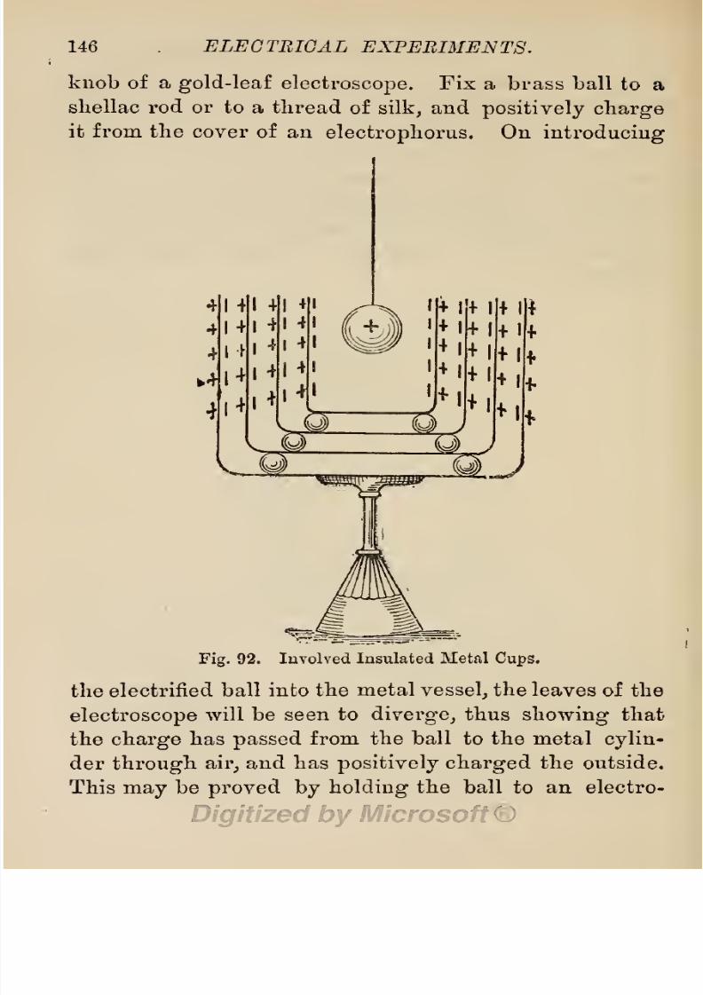
8/20/2019 electrical experiment.pdf
http://slidepdf.com/reader/full/electrical-experimentpdf 164/325
146
ELECTRICAL
EXPERIMENTS.
knob
of
a
gold-leaf
electroscope.
Fix
a
brass
ball
to a
sliellac rod or to a
thread
of
silk,
and
positively charge
it from the
cover of an
electrophorus.
On
introducing
Fig.
92.
Involved
Insulated
Metal
Cups.
the electrified
ball
into
the
metal
vessel,
the
leaves
of
the
electroscope
will
be
seen
to
diverge,
thus
showing
that
the
charge
has
passed
from the
ball
to
the
metal
cylin-
der
through
air,
and
has
positively
charged
the
outside.
This
may
be
proved
by
holding
the
ball
to
an electro-

8/20/2019 electrical experiment.pdf
http://slidepdf.com/reader/full/electrical-experimentpdf 165/325
EXPERIMENTS
WITH
STATIC
ELECTRICITY.
117
scope,
and
testing*
the
interior
of
the
metal
vessel with
a
proof plane.
If
now we
procure
some
three or
four
such
metal
vessels,
each
larger
than
the
other,
and
insulate them
from
each
other
by
cakes of
shellac,
as
slioAvn
in
Fig.
92,
connecting
the
outer
vessel
to
an
electroscope,
as
before,
the same result
will
be
obtained,
and,
if
the inside
vessel
is
connected
to
earth
by
touch-
ing
it
with
a
finger,
the
leaves
of
the
electroscope
will
immediately
collapse.
__J9lS3II 13=:
Fig.
93.
Insulated Ball
and
Cylinder coated
with
Tinfoil.
5.
Procure a
piece
of
well-seasoned
walnut,
mahogany,
or
other
hard
wood
capable
of
furnishing
a
cylinder
10
inches
in
length
by
3
inches
in
diameter,
with
rounded
ends.
Turn
this
quite
smooth,
and
smoothly
coat
it with
tinfoil.
Half-way
along
on one
side,
bore
a
socket
with
a
centre-bit,
to
fit
on
a
glass
rod
destined
to
form
an
insulating
handle or
the
pillar
of
an
insulating*
support
when
the
other end
is
cemented into
a suitable
foot
or
stand. On
the
opposite
side,
drill
five
T
\-inch
holes, to

8/20/2019 electrical experiment.pdf
http://slidepdf.com/reader/full/electrical-experimentpdf 166/325
148
ELECTRICAL EXPERIMENTS.
the
depth
of
^-inch,
one
in the
centre,
one
at
each
end,
^-inch
in
from
the rounded
end,
and
two
midway
be-
tween
the centre
and
ends.
A
polished
brass
cylinder,
similarly shaped
and
mounted,
may
be
used
instead,
if
desired.
The
form is shown
in
Fig.
93,
and
the
prices
are
respectively
4s.
and
13s. 6d. The
first
experiment
with
this
may
be
tried
on a
charged
electrophorus
with-
Fig.
94.
Experiment
with
Insulated
Cylinder
and
Electrophorus.
out
a
cover.
Get
five
pith
balls,
and
glue
them
to
pieces
of
linen
thread
3
inches
in
length,
then
attach these
threads
to
wooden
pegs
fitting
in
the
five
small
holes
on
the
cylinder.
Holding
the
insulating
support
in one
hand,
and
bringing
the
cylinder
in
a vertical
position,
with
its
lower
end
over the
electrophorus,
as
shown
in

8/20/2019 electrical experiment.pdf
http://slidepdf.com/reader/full/electrical-experimentpdf 167/325
EXPERIMENTS
WITH
STATIC
ELECTRICITY.
149
Fig.
94,
the
lower
pith
ball will be
seen to
diverge
at
a
wide
angle,
the
next
at
a
more
acute
angle
;
the middle
ball
will
lie
close to
the
cylinder,
unaffected
by
the
charge
;
the
next will
diverge slightly,
and
the
top
ball
still
wider;
thus
showing
that
the whole
cylinder
is
inductively
charged
with
electricity,
and
the
extremities,
as
well
as
the
central
portion,
exhibit
all
the
peculi-
arities
of
a
charged
steel
magnet
with
opposite
poles
and
a neutral
space
between.
Fig.
%.
Insulated
Cone
coated
with Tinfoil.
In
the
next
experiment
this
property
of
static electric
charge
is
even more
pronounced
and
clearly
illustrated.
It is
performed
with two
spherical
condensers
placed
at
short
distances
from
each
end
of
the
cylinder
used in
the
first
experiment.
These
condensers
may
be
wooden
balls
some
4 or
5
inches
in
diameter,
mounted
on
in-
sulating
pillars,
and coated
smoothly
with
tinfoil,
or
they
may
be made of
metal,
and
similarly
mounted
(see
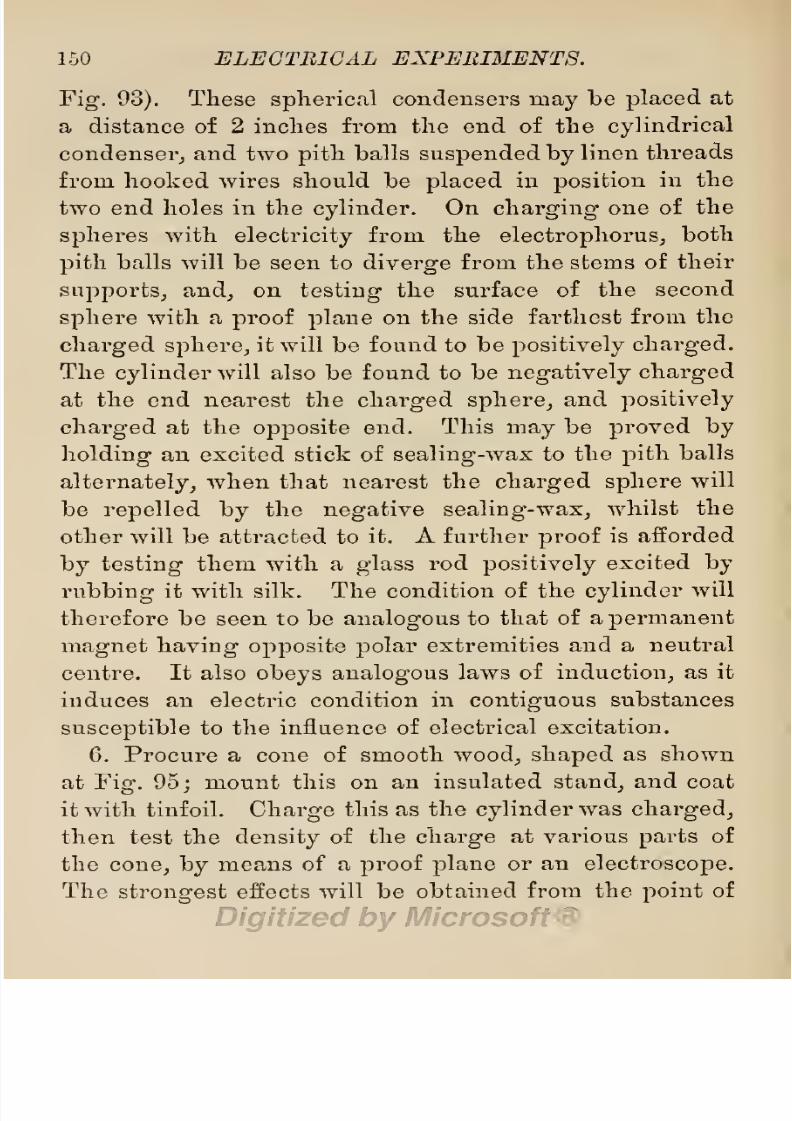
8/20/2019 electrical experiment.pdf
http://slidepdf.com/reader/full/electrical-experimentpdf 168/325
150 ELECTRICAL EXPERIMENTS.
Fig.
93).
These
spherical
condensers
may
be
placed
at
a
distance
of
2
inches from
the end of
the
cylindrical
condenser,
and
two
pith
balls
suspended
by
linen
threads
from
hooked
wires
should be
placed
in
position
in
the
two end
holes
in
the
cylinder.
On
charging
one
of
the
spheres
with
electricity
from
the
electrophorus,
both
pith
balls will
be
seen to
diverge
from
the
stems
of
their
supports,
and,
on
testing
the
surface of
the second
sphere with
a
proof
plane
on
the
side
farthest
from
the
charged sphere,
it will
be found
to
be
positively
charged.
The
cylinder
will also
be found
to
be
negatively
charged
at the end nearest the
charged
sphere,
and
positively
charged
at
the
opposite
end.
This
may
be
proved
by
holding
an
excited
stick
of
sealing-wax
to
the
pith
balls
alternately,
when
that nearest
the
charged
sphere
will
be
repelled
by
the
negative
sealing-wax,
whilst
the
other will
be
attracted to it.
A
further
proof
is
afforded
by testing
them with
a
glass
rod
positively
excited
by
rubbing
it
with silk.
The
condition
of
the
cylinder
will
therefore
be
seen to
be
analogous
to
that of
a
permanent
magnet
having
opposite polar extremities
and
a neutral
centre.
It
also
obeys
analogous
laws of
induction,
as it
induces
an
electric condition
in
contiguous
substances
susceptible
to the influence of
electrical
excitation.
6.
Procure
a
cone
of
smooth
wood,
shaped
as
shown
at
Fig.
95;
mount
this on
an insulated
stand,
and
coat
it
with
tinfoil.
Charge
this
as
the
cylinder
was
charged,
then
test the
density
of the
charge
at
various
parts
of
the
cone,
by
means
of a
proof
plane
or
an
electroscope.
The
strongest
effects
will
be obtained
from
the
point
of

8/20/2019 electrical experiment.pdf
http://slidepdf.com/reader/full/electrical-experimentpdf 169/325
EXPERIMENTS WITH
STATIC
ELECTRICITY.
151
the
cone,
and
the least
effects
from
the
largest
and
most
bulky part.
This shows
the
tendency
of electric
charge
to
concentrate
itself
towards
points
and
edges,
much
the
same
as
magnetic
charges
are most
strongly
observable on
the
edges
of
magnets.
§
44.
Leydeil
Jars.
The
range
of
experiments
with
an
electrophorus
may
be
largely
extended
by
using
it
to
charge
Leyden
jars,
and
then
using
these
in
performing
experiments.
A
Leyden
jar
is a condenser
formed
of
a
Fig.
96.
Leyden
Jar.
glass
jar
or
wide-mouthed
glass
bottle,
coated
inside
and outside with
tinfoil
up
to
within an
inch
or
so
of
the
top.
The
mouth
of
the
jar
is
stoppered
with
a
bung
of
polished
hardwood,
through
which
passes
a brass rod
terminating
on the
top
in a
brass
ball,
and
having
a
piece
of brass chain
depending
from its
inner
end,
or
else
an
extension
to touch the
bottom of
the
jar.
A
Leyden
jar
is
shown at
Fig.
96,
and
its
construction
is
clearly
described
and
illustrated
in
Electrical
Instru-
ment
Making,
pp.
71-75.

8/20/2019 electrical experiment.pdf
http://slidepdf.com/reader/full/electrical-experimentpdf 170/325
152
ELECTRICAL
EXPERIMENTS.
When
the
jar
is
intended to
be
charged
from
an
electrical
machine,
the
brass
rod
is
made
longer
than
usual,
and
is
bent in
the
form
of a
shepherd's
crook,
for
convenience
in
hanging
the instrument on the
prime
conductor
of
the
machine. Two or
more
Leyden jars
placed
in
a wooden
tray
lined with
tinfoil,
and
connected
together
on
top
(as
shown at
Fig.
97),
constitutes
an
electric
battery,
which
is
capable
of
receiving
a
higher
Fig.
97.
Battery
of
Leyden
Jars.
charge than
a
single
jar.
When
a
jar
is
coated
inside
and
out with
diamond-shaped
pieces
of
tinfoil
instead
of
a
continuous sheet
(as
shown
at
Fig.
98),
the
jar
is
named
a
spotted
jar,
and
forms
the means
of
a
very
pretty
experiment,
in
which
the
charge
and
discharge
breaks across the
patches
of
tinfoil
in
the
form
of vivid
sparks.
Messrs.
King,
Mendham
&
Co.
make
a
special
form,
which
they
name a
High
Insulation
Leyden
Jar.
In
the
construction
of this
jar,
advantage
is
taken of
the
known
tendency
to
electrical
leakage
through
the

8/20/2019 electrical experiment.pdf
http://slidepdf.com/reader/full/electrical-experimentpdf 171/325
EXPERIMENTS
WITH
STATIC
ELECTRICITY.
153
wooden
cover of
an
ordinary jar,
to
dispense
with
a
cover
altogether,
and thus attain
a
higher
state
of
insulation.
This
fox*m
is
shown at
Fig.
99.
Leyden
jars
without
covers
are more
easily
made than
those
with
covers.
Open
glass jars,
such as
those
used
by
con-
fectioners,
should be selected.
They
are
easily
coated
inside
and
out
with tinfoil.
The brass stem
of
the
jar
may
be
fixed
into
a
cross-piece
of
sheet lead
or
to
a
Fig.
98.
Spotted
Leyden
Jar.
Fig.
99.
High
Insulation
Leyden
Jar.
cone
of lead,
and
this
may
be
secured
to
the
bottom
of
the
jar
by
a
touch,
here and
there,
of
thick
shellac
varnish,
or
glue,
or
china
cement.
Fig.
100 shows
a
form
of
Leyden jar
with
movable
parts,
destined for
use
in
experiments
to
demonstrate
whether
the static
charge
is retained
in
the
glass
or
in
its
coatings
of
tinfoil.
It
consists
of
a
thin
glass
tumbler,
and
a tin
cup
made to
fit
the
outside
of
the
tumbler,
and
a
cone
of
wood
coated
with
tinfoil
to
fit
the
inside
of the
tumbler,
this
cone
being
furnished
with

8/20/2019 electrical experiment.pdf
http://slidepdf.com/reader/full/electrical-experimentpdf 172/325
154
ELECTRICAL
EXPERIMENTS.
the usual
brass
stem and knob in
use with
ordinary
Leyden
jars.
The
prices
of
ordinary Leyden
jars
run
from
2§.
for
a
^-pint
jar,
measuring
4
in.
x 2
in.,
up
to
8s.
Qd.
for
a
2-quart jar,
measuring
10
in.
x
5
in.
Bat-
teries of
jars
cost 18s.
6c/.
for
4
jars
of
pint
size,
up
Fig.
100.
Leyden
Jar
with
Movable
Coatings.
to
£4
10s. Qd.
for
batteries
of 9
jars
of
2-quart
size.
Diamond
spotted
or
spangled jars
cost
from
Qs. to
8s.
Qd.,
according
to size.
Jars
with
movable
coatings,
cost
from
6s.
Qd. to
8s.
Qd:
each.
High
Insulation
jars,
cost
3s.
Qd.
and 4s.
Qd.
each.
§
45.
Experiments
with
Leyden
Jars.
With a
charged
Leyden jar,
a
large variety
of
experiments

8/20/2019 electrical experiment.pdf
http://slidepdf.com/reader/full/electrical-experimentpdf 173/325
EXPERIMENTS WITH
STATIC
ELECTRICITY.
155
may
be
performed,
and
with a
battery
of
such
jars
the
scope
of the
experiments
may
bo
extended.
Very
many
of
the
experiments performable
with
the
spark
from
an
induction
coil,
detailed
in
§§
26
to
28,
may
also
be
performed
with
the
spark
obtained
from
a
charged
Leyden
jar.
The most
prominent
and
interesting
of
these
are:
—
1.
Deflagration
of
Wire. 2.
Deflagration
of
Metal
Filings.
3.
Deflagration
of
Metal Foil.
4.
Ignition
experiments.
5.
Lighting
Gas.
6.
Exploding
Fuses,
and
Firing
Electric Pistols
or
Mortars.
Besides
these,
the
following
experiments
may
also be
performed.
1.
Charging Leyden
Jars.
Leyden
jars,
as first
seen
by
the amateur
electrician,
student of
electricity,
and
experimenter
in
scientific
subjects,
appear
to be
an
ingenious contrivance
for
bottling
electricity
under
pressure.
It
would
seem
as
if
an
electric
fluid
was
injected
in
small
quantities
from an
electric machine
into
a
jar,
and
held
there
under
pressure,
much
the
same as
mineral
waters,
ginger
beer, lemonade,
etc.,
are held under
pressure
in
glass
bottles.
Such,
how-
ever,
is
not the
case.
Whatever
electricity
may
be,
it
is
not
a fluid
in
itself,
nor
can it
be
said
to
be held
in
a
Leyden
jar
under
pressure,
since the tension
or
pressure
is
the
same
in
jars
of all
sizes,
and no
method
of
pumping,
or
other
method
of
compressing
fluids,
has
yet
been found to
increase the
tension
of
an
electric
charge.
The
volume
or
quantity
of
the
charge
increases
with
the
size of
jar,
but
the tension
remains
the
same.
The condition of
a
charged
Leyden
jar
is
much
the
same
as
that
of
a
magnetized
steel
bar.
One
of
its

8/20/2019 electrical experiment.pdf
http://slidepdf.com/reader/full/electrical-experimentpdf 174/325
156
ELECTRICAL
EXPERIMENTS.
coatings
is
positively
and
the
other
negatively
electri-
fied. All
its
parts
are made
up
of
polarized
molecules
of
matter,
much
the
same
as
those
of
a
bar
of
magnetized
steel.
Its
capacity
for
charge
is
limited
by
the
quality
of
the
material
employed
in its
construction,
and
the
extent of its
polarizable
surface. It
obeys,
however,
the
laws
of
electric
circuit,
and
therefore
cannot
be
fully
charged
if
placed
on
an
insulating support.
There
must
be
a
complete
chain
of
conductors
between
its
outer and inner
coating,
so
as to form
a
complete
circuit,
although,
to
ensure
success,
some of these
must
be such
bad
conductors
as
glass,
and
the
human
body.
To
demonstrate
this,
place
a
Leyden
jar
on an
insulating
support
near the
prime
conductor
of
an
electric
machine.
When
within
striking
distance
of
the
machine,
one
or
two
sparks
will
be seen
to
pass
from
the
conductor
to
the
knob of the
jar,
and
the
inner
coating
will receive
a
faint
charge,
but
the outer
coating
will be unaffected.
Now
grasp
the
jar
with
one
hand,
and
thus
provide
a
circuit
of
better
conductors
than
glass,
or connect the
outer
coating
to
earth
by
means
of
a piece
of
sheet
metal
and
a
piece
of
clock-chain,
and
again
attempt
to
charge
the
jar.
A
series
of
sparks
will
now
pass
to
the
jar,
and it
will
be
fully
charged
inside
and outside.
It
is
therefore
usual
to
place
the
jar
in connection
with
the
earth,
or
to
hold
it
in
one
hand whilst
being
charged.
The
jar
may
then
be
charged
by
holding
it
to the
conductor
of
a
machine,
or
from
an
electrophorus,
or
by being placed
in
connection
with
an
induction
coil,
as
directed
in
§
30,
p.
91.

8/20/2019 electrical experiment.pdf
http://slidepdf.com/reader/full/electrical-experimentpdf 175/325
EXPERIMENTS
WITH
STATIC
ELECTRICITY.
157
If we
wish
to
have
at our
command
a
large
quantity
or
volume
of
electricity,
we
must
employ,
either
large
jars
of
large
capacity,
or connect
several
jars
together
Fig.
101.
for
quantity,
just
the same
as in a
voltaic
battery,
that
is
by
connecting
their
positive
poles
(knobs)
together,
and their
negative
poles
(outer
coatings)
all
together

8/20/2019 electrical experiment.pdf
http://slidepdf.com/reader/full/electrical-experimentpdf 176/325
158
ELECTRICAL
EXPERIMENTS.
(as
shown at
Fig.
97),
the
latter
being easily
achieved
by
placing
the
jars
in
a
tray
lined
with
tinfoil.
When
we
wish
to
have
the
charge
at
a
higher
tension
than
can
be obtained
from
one
jar,
we
must
connect
a number
of
jars
together
in
series,
just
the
same
as
the cells of
a
voltaic
battery
are
connected,
—
that
is,
connect
the
knob
of
one
jar
to the outer
coating
of the
next,
and
the
knob of
this
to
the
next,
and
so
on
through
the
series,
each
jar,
except
the
last
in
the
series,
being
placed
on
an
insulating
support,
as
shown
at
Fig.
101.
Fig.
103.
Lane's
Electrometer.
The
whole series
may
then be
charged
from
one
source
at
the
same
time,
and
this method
of
charging
has been
named
charging
in
cascade.
Other
methods
of
charging
Leyden
jars
in
cascade,
are
shown
in the
annexed
figures,
taken from
Mr.
Bottone's
book
on
Electricity
and
Magnetism.
The
capacity
of a
jar
for
electric
charge
depends
upon
the extent
of its
coated
surface,
and
the
thick-
ness
of
the
glass
employed
in
its
construction.
Thick
glass
offers
too much resistance
to the
charge.
Accord-
ing
to
Wheatstone,
the
quantity
of
electricity
which
can
be
got
into a
jar,
is
proportional
to the
extent

8/20/2019 electrical experiment.pdf
http://slidepdf.com/reader/full/electrical-experimentpdf 177/325
EXPERIMENTS
WITH
STATIC
ELECTRICITY.
159
of
its
coated
surface,
and
inversely
proportional
to
the
square
of
the
thickness of
the
glass.
The
limit of
charge
may
be determined
by
means of a
Henley's
quadrant
electrometer
(Fig.
83,
p.
130),
attached to
the
jar being
charged,
or
a
Lane's electrometer
(Fig.
103),
for
determining
the
striking power
of the
charge
through
air
space,
or
a
Harris'
unit
phial
(Fig.
104),
placed
in
circuit
with
the
jar being
charged.
The
Henley
quadrant
is
merely
a
pith
ball
attached to
Fig.
104.
Harris'
Unit Phial
Electrometer.
the
end of a
shellac
or
whalebone
arm,
and
pivoted
to the
upper
part
of a
graduated
quadrant.
The
pith
ball rises
as
the
charge
increases
in
the
jar.
This
instrument
is sold for
3s. Gel.
Lane's
electrometer is
merely
a
Leyden
jar
placed
near a
metal
arm,
as shown
in the
figure.
The
outer
coating
of the
jar
being
charged,
is
insulated,
and
then connected
by
a
wire to
the
knob
of this
extra
jar,
the outer
coating
of
which
is
connected
with
the
ground.
The
knobbed
arm
is
then
brought
close
to
the
knob of the
jar,
and after-
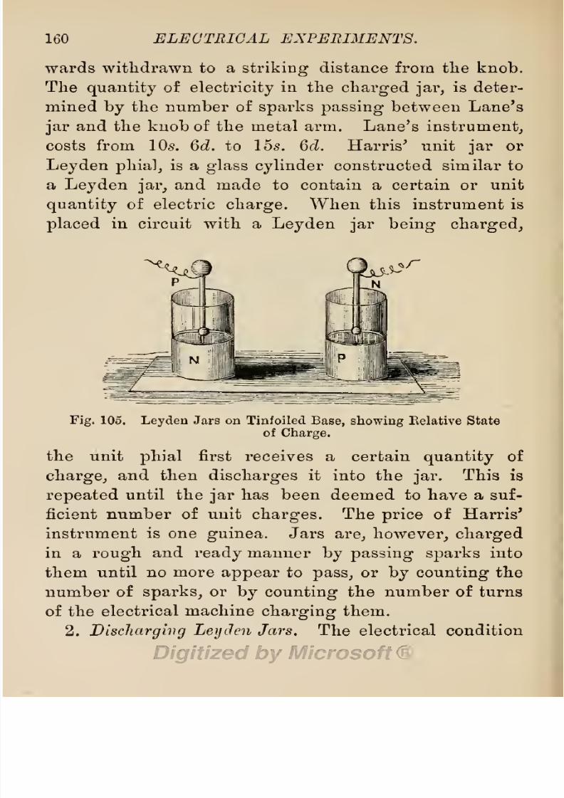
8/20/2019 electrical experiment.pdf
http://slidepdf.com/reader/full/electrical-experimentpdf 178/325
160
ELECTRICAL
EXPERIMENTS.
wards
withdrawn to
a
striking
distance from the
knob.
The
quantity
of
electricity
in
the
charged jar,
is
deter-
mined
by
the
number
of
sparks
passing-
between Lane's
jar
and
the
knob
of
the
metal
arm.
Lane's
instrument,
costs
from 10s. 6d.
to 15s.
Qd.
Harris'
unit
jar
or
Ley
den
phial,
is
a
glass
cylinder
constructed similar to
a
Leyden
jar,
and
made to
contain
a certain
or
unit
quantity
of
electric
charge.
When
this
instrument
is
placed
in
circuit
with a
Leyden
jar
being
charged,
Fig.
105.
Leyden
Jars
on
Tinfoiled
Base,
showing
Relative
State
of
Charge.
the unit
phial
first
receives a certain
quantity
of
charge,
and then
discharges
it
into the
jar.
This
is
repeated
until the
jar
has
been
deemed to
have
a
suf-
ficient number
of
unit
charges.
The
price
of
Harris'
instrument
is
one
guinea.
Jars
are,
however,
charged
in
a
rough
and
ready
manner
by
passing sparks
into
them
until no
more
appear
to
pass,
or
by
counting
the
number
of
sparks,
or
by
counting
the
number of turns
of the electrical
machine
charging
them.
2.
Discharging
Ley
Jen
Jars. The
electrical
condition

8/20/2019 electrical experiment.pdf
http://slidepdf.com/reader/full/electrical-experimentpdf 179/325
EXPERIMENTS WITH STATIG
ELECTRICITY.
161
of
a
Leyden
jar
when
charged,
is
negative
on
one
coat-
ing,
and
positive
on
the
other.
As
ordinarily charged,
the
inner
coating
is
positive,
and
the
charge
has
a
high
potential
or
pressure.
The
outer
coating
is
negative,
and
is
insulated
from the inner
coating
by
the
glass
of
the
jar.
Unless
the
glass
is
defective or
the
jar
too
highly
charged,
this
insulating
medium
is
quite
sufficient
to
prevent
the
two
coatings being
connected
in circuit.
When,
however,
a conductor is
allowed
to touch
the
knob
on
top
of
the
jar
and the
outer
coating,
the
circuit
is
completed,
and
the
electricity
is
said
to
be
discharged.
If, therefore,
we take a
half-pint
Leyden
jar
and
charge
it
with
electricity,
then
grasp
the
jar
with
one
hand,
whilst
we
touch the knob of the
jar
with
the
knuckles
of
the
other
hand,
a
spark
will
pass
from
the
knob
of
the
jar
to
our
knuckles,
because the
body
forms
a
con-
ductor and
completes
the
circuit
of
conductors.
If
the
jar
stands
on an
ordinary
table,
uninsulated
from
the
ground,
and
its
knob
is
touched
in
a
similar
manner,
the
charge
will
also
take
advantage
of this
closing
of
the
circuit
and
discharge
itself
through
the
body,
tho
table,
and
the
floor of the
apartment,
all
of
which
are
conductor's
to
electric
currents of
high
potential.
If
the
charged
jar
is
placed
on an
insulating
block of
glass,
or
an
insulating
stand,
then
touched
with the
knuckles,
only
a
partial
discharge
takes
place
in
the
form of
a faint
spark.
If
now we touch
the
outer
coating,
a
spark may
be
obtained from
it
also,
then
another
may
be
got
from
the
knob,
another
from
the
outer
coating,
and
so
on
until
all
the
charge
has
been
M

8/20/2019 electrical experiment.pdf
http://slidepdf.com/reader/full/electrical-experimentpdf 180/325
162 ELECTRICAL
EXPERIMENTS.
withdrawn
in
small
quantities.
These
experiments
may
only
be
performed
with small
jars.
On
no
account
should
we
attempt
to
take a
charge
from
a
large
jar,
or
a
battery
of
jars,
as the sudden
shock to
the
nerves
by
the
passage
of
a
large
volume
of
current at a
high
tension,
is
likely
to
have
disagreeable
and
injurious
results.
3. The
Use
of
Dischargers,
On account
of this
danger,
it
becomes
necessary
to use
specially
insulated
instru-
ments
in
experiments
with
Ley
den
jars,
and
these
Fig.
106.
Discharging
Tongs.
instruments
are
known
as
dischargers.
The
most
simple
form is
named
a hand
discharger,
and
is
simply
a
pair
of
wires,
terminating
in
brass
balls,
fixed
to
a
compass
adjustment,
and
attached
to
an
insulating
glass
handle.
In
the next
form
(Fig.
106),
two
glass
or
ebonite
handles
are
provided,
and
the
instrument
is
named
discharging
tongs.
To
discharge
the
jar
with the
hand
discharger,
first
adjust
the
two
arms
to
a
distance
apart equal
to
that
between the
outer
coat-
ing
of the
jar
and
its
knob,
then
place
one ball on
the
8/20/2019 electrical experiment.pdf
http://slidepdf.com/reader/full/electrical-experimentpdf 181/325
EXPERIMENTS
WITH
STATIC
ELECTRICITY.
163
outer
coating,
and
bring
the
other
gradually
to
the
knob
of
the
jar.
When
near
to
it,
but
not
quite
touch-
ing,
a
spark
will
flash
from the
knob,
and this
is
an
evidence
of the
jar
being
discharged.
On
bringing
the
ball
nearer,
after
the
first
discharge,
a feeble second
spark
may
be
obtained. With
the
discharging tongs,
both
hands
may
be
employed,
and
the
arms
of
the
instrument
adjusted
to a
nicety
whilst
approaching
them
to
the
knob.
Hand
dischargers
cost
3s.
6d.,
and
discharging
tongs
from 6s.
to
9s.,
according
to
length
and
finished
workmanship
;
but
both
may
be
easily
made,
by
the
amateur
experimentalist,
from a
few
pieces
of wire
and
glass.
Knobs must be used
instead of
points
as
terminals
to
all
electro-static
instru-
ments,
because best
effects are
obtained from
knobs,
the
spark
from
a
point
being
small and of a
feeble
character,
and all
points
and
sharp
angles
draw
off
electric
charge
into
the
air
quietly
and
silently.
Discharging Leyden
Jars
ivith
Movable
Coatings.
The
discharge
of
a
Leyden
jar
furnished
with
movable
coatings,
as
shown at
Fig.
100,
p.
154,
provides
means
for
a
very
interesting
experiment,
showing
that
the
electric
charge
is
taken
up
and
retained
by
the
glass
of
the
jar.
After
the
jar
has been
charged,
it
must
be
placed
on an insulated table
(Fig.
114,
p.
169),
or on a
cake
of
resin.
The
inner
coating
may
be removed
by
placing
a
glass
rod under
the
hook,
and
lifting
it out
of
the
tumbler. Then
the
glass
vessel
is
raised,
and the
metal
cup
removed
and
placed
on
a
table,
leaving
the
glass
tumbler alone on the
insulated
table.
On
testing

8/20/2019 electrical experiment.pdf
http://slidepdf.com/reader/full/electrical-experimentpdf 182/325
164
ELECTRICAL EXPERIMENTS.
both
inner
and
outer
coatings
with the
proof
plane,
little
or
no
charge
will
be
discovered
;
but
on
restoring
them
to their former
positions
and
then
testing
them,
a
sharp
discharge
may
be
obtained
in
the
form
of a
shock
or a
spark.
When
using
charged Leyden jars
in
the form of
a
battery
for
large experiments,
and
also
when
using
condensers
(noted
further
on),
we
must
employ
another
form
of
discharger,
shown
at
Fig.
108,
and
known
as
Fig.
107.
Discharging
a
Lejden
Jar.
Henley's
discharger.
This is similar
to
the
instrument
in
use for
discharges
from induction
coils,
in
fact one
or both
may
be
used
for
the
same
purpose
by
merely
substituting
knobbed
terminals
for
points,
or
the
reverse
as
required.
A
special
form
of
this
instrument,
fur-
nished
with
cup
and
ball
joints
and
a
fixed
insulated
table,
as
shown
in
the
annexed
figure,
costs
25s.
6d.
This is a
superior
and
handy
combination
of
Leyden
jars
and
discharger,
made
by
Messrs.
King,
Mendham
&
Co.
The
insulated
discharger
rods work
in
a
socket

8/20/2019 electrical experiment.pdf
http://slidepdf.com/reader/full/electrical-experimentpdf 183/325
EXPERIMENTS
WITH
STATIO
ELECTRICITY.
165
pierced
through
a
brass
ball,
and this
works
in
a
cup.
The
dischai^gers
can
therefore be
adjusted
to
any
Fig.
108.
Discharging
Insulated
Leyden
Jar.
Fig.
109.
Henley's
Universal
Discharger.
distance
within
their
range,
and
the
discharge
directed
at
any
angle.
The
jars maybe
charged
as
they
stand-

8/20/2019 electrical experiment.pdf
http://slidepdf.com/reader/full/electrical-experimentpdf 184/325
166
ELECTRICAL
EXPERIMENTS.
or
the
instrument
may
be
used
when
connected
to
an
outside
source
such
as
a
battery
of
jars
or
an
electric
machine,
in
which
case
the
jars
are useful
in
taking
up
an
extra
charge.
The
central
table
has its
foot
em-
bedded
in
paraffin
wax
contained
in
a
glass
jar,
and
thus a
high
insulation
is
attained.
The
price
of
this
instrument is
£1
5s. 6d.
A
cheap arrangement
for
this
experiment
(from
Mr.
Bottone's
new
book)
1
is
shown
at
Fig.
108.
Fig.
110.
Electrical Chimes.
4.
Electrical
Chimes.
When
experimenting
with
a
charged
rod of
sealing-wax
and
a
pith-ball
electroscope,
we observed
that
the
pith
ball
was first
attracted
to
the
rod,
then
repelled
as it became
charged.
This
experi-
ment
may
be
repeated
with
a
charged
Leyden
jar
on
a
1
Electricity
and
Magnetism,
Whittaker
&
Co., London,
price
3s. 6d.

8/20/2019 electrical experiment.pdf
http://slidepdf.com/reader/full/electrical-experimentpdf 185/325
EXPERIMENTS
WITH
STATIC
ELECTRICITY.
107
stand,
as
shown
at
Fig.
110,
where
the
jar
is shown
with
a
small
bell
instead
of
a
knob,
and
another bell
mounted
on
a
pillar
near it.
The
projecting
arm
above
this
bell,
carries
a
small
brass
ball
suspended
to
a
fibre of cocoon
silk.
The
pillar
stands on
a
strip
of
tinfoil
in
contact
with the
outer
coating
of
the
jar.
When
the
jar
is
charged,
its
bell will attract the
metal
ball
to
itself,
which
then
becomes
charged
positively,
and,
as
a
con-
sequence,
will
be
repelled against
the
negatively
charged
bell
on
the
pillar
;
this
in
turn
will
give
up
a
part
of
its
negative
charge
to
the
ball and
repel
it
toward
the
jar.
This
to-and-fro
movement
will
be
repeated
until
the
jar
has
been
slowly
discharged.
Fig.
111.
Electric
Mortar.
5.
Electric
Mortar
or
Cannon.
The
charge
from
a
battery
of
Leyden
jars
may
be
utilised to
fire
a
fuse,
or
fire
gunpowder.
This
may
be
illustrated
by
means
of
the
following
experiment.
Procure
a
heavy
block of

8/20/2019 electrical experiment.pdf
http://slidepdf.com/reader/full/electrical-experimentpdf 186/325
168
ELECTRICAL
EXPERIMENTS.
hard
wood,
and
turn
out
(in
a
lathe)
a
model of
a
cannon
or
a
mortar
with
thick sides
and a
f
-inch
bore. Near
the
bottom
of
the
bore,
insert
two brass
wires with
rounded
ends
at a fractional
distance
apart.
The
outside
ends
of these wires
should
terminate
in
a
shepherd's
hook
and
knob,
or
as
shown
in
the annexed
figure
(Fig.
111).
The
cannon
or
mortar
may
be
charged
with
equal
parts
of chloride of
antimony
and
chlorate
of
potash finely
pow-
dered
separately,
then mixed
with a
feather.
Connect
one
of the
hooked ends
by
means
of
a
clock-chain
with
Fig.
112.
Insulated
Cup.
Fig.
113.
Glass
or
Card
Piercer.
a metal
plate
on
which
the
charged
jar
rests,
connect
the
opposite
hooked
end
by
means of
a
piece
of
clock-
chain
to one
limb
of
the
discharging
tongs,
and
then
discharge
the
jar
by
touching
the knob
in
the usual
way
with
the other
limb
of
the
tongs.
If all
has
been
properly
arranged,
the
charge
in
the
mortar
will
explode
with
a
loud
report.
Of
course
the
charge
must
be
small,
and
reasonable
care taken
to
prevent
injurious
results
from
the
explosion.
A
Henley's
discharger may
be
similarly
connected
to
a
jar
or a
battery
of
jars,
and

8/20/2019 electrical experiment.pdf
http://slidepdf.com/reader/full/electrical-experimentpdf 187/325
EXPERIMENTS
WITH
STATIC
ELECTRICITY. 169
various
substances,
such
as
powder, gun-cotton,
lycopo-
dium,
etc.,
as
described
in
the
experiments
with
in-
duction
coils,
may
be
inflamed
by
discharging
the
jars
through
them.
When
it is intended
to
inflame
phos-
phorus
or ether
and
other
inflammable
liquids,
they
are
usually
held
in
an
insulated
cup,
such
as
that
shown
at
Fig.
112,
the
price
of which is 3-s.
6.
Piercing
Cards
or Glass.
The
apparatus
shown at
Fig.
114.
Insulated
Table.
Fig.
113 is
intended
to
facilitate the
experiment
of
piercing
a
card
or
a
piece
of
glass
by
discharging
a
Leyden jar through
a
card
or
glass placed
horizontally
between
the
two
vertical
knobs
shown
in
the
figure.
The
upper
knob is
adjusted
until
the best
effect
is ob-
tained.
The
price
of
this
apparatus
is
9s.
7.
Imitation
Lightning.
A
thunderstorm
is
caused
by
an accumulation
of
electric
charge
in
clouds,
which
form condensers
similar
to
massive
Leyden
jars
;
and

8/20/2019 electrical experiment.pdf
http://slidepdf.com/reader/full/electrical-experimentpdf 188/325
170
ELECTRICAL
EXPERIMENTS.
when
some
of
these
become
positively charged
with
electricity
at
a
high
tension,
whilst
others are
negatively
charged,
the overbalanced
force
naturally
tends to
ob-
tain
a
balance
by
a
discharge
of
the
higher
potential
charge
into
a
lower.
This
discharge
sometimes takes
place
between
neighbouring
clouds,
when
these
are
differently
charged.
This
celestial
discharge may
be
imitated
by enveloping
the
discharger
balls
of
a
Henley's
discharger
with
masses
of cotton
wool
to
resemble
clouds,
connecting
them
in
circuit
with
a
battery
of
Leyden
jars,
and
bringing
the clouds
gradually
toward
each
other
until
the
discharge
takes
place
between
them.
The
loud
crackling
noise
of
the
spark
will
give
some
idea of the
cause
of
thunder,
if
we take
into
con-
sideration
the
enormous
potential
of
a
flash
of
lightning
as
compared
with that
of
a
spark
from
a
Leyden jar,
taking
50,000
volts to
represent
the
tension
of
an
inch
spark
in
air.
Electric
discharge
always
takes
place
from cloud to
earth,
or
from
earth
to
cloud,
over
paths
or
lines
of
least
resistance,
or,
which
means
the
same,
through
a
chain of
best
conductors.
If, therefore,
the line
of least
resistance lies
between
such
a bad conductor
as
air and
a
chain
of alternate
good
and
bad
conductors
such as
masses
of
metal
separated by
wood
or
by
masonry,
the
discharge
will
take
place
in
the
latter,
but
the strain in
the
bad
conducting
portion
of
the
chain
will
be
so
great
as
to
cause
disruption
of the chain.
This
is shown
by
means of model
buildings,
named
in makers'
price
lists,
thunder-houses.
A
model house
is
made
of
wooden
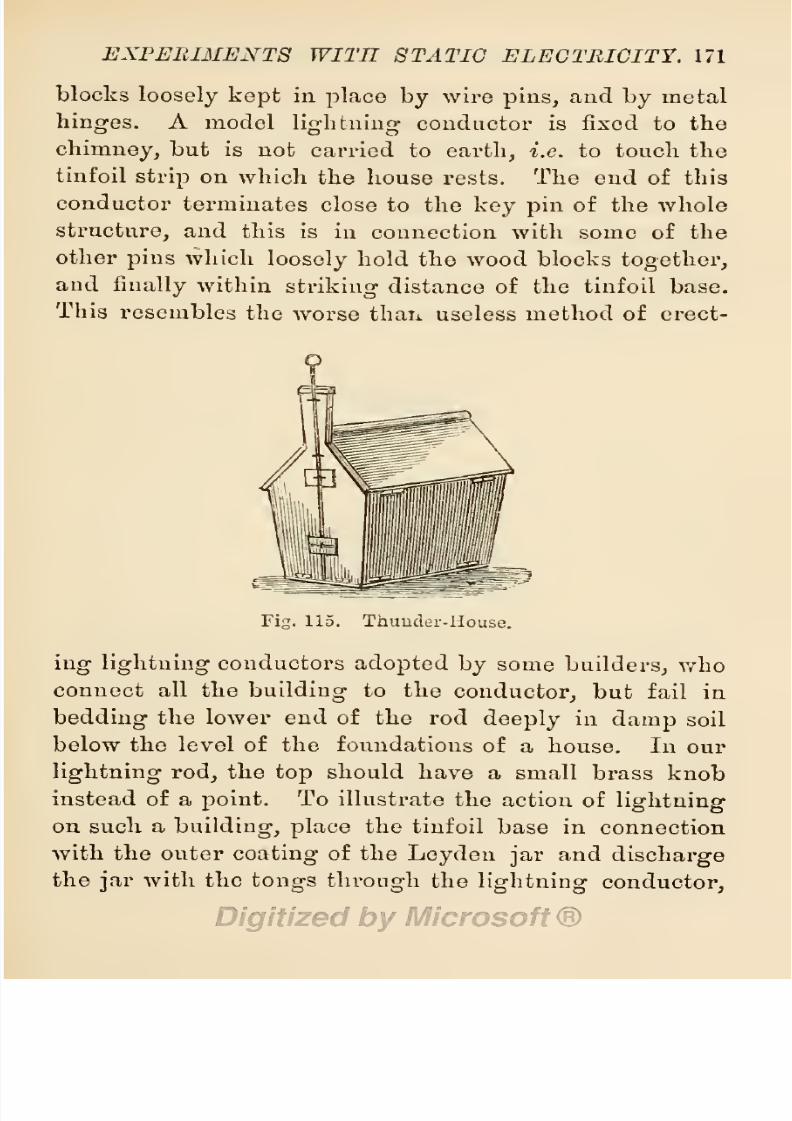
8/20/2019 electrical experiment.pdf
http://slidepdf.com/reader/full/electrical-experimentpdf 189/325
EXPERIMENTS
WITH
STATIC
ELECTRICITY.
171
blocks
loosely
kept
in
place
by
wire
pins,
and
by
metal
hinges.
A
model
lightning
conductor
is fixed
to
the
chimney,
but is
not
carried to
earth,
i.e.
to
touch
the
tinfoil
strip
on
which
the
house rests.
The
end of this
conductor
terminates
close
to
the
key
pin
of
the
whole
structure,
and
this
is
in
connection
with
some of the
other
pins
which
loosely
hold
the
wood
blocks
together,
and
finally
within
striking
distance
of the
tinfoil base.
This
resembles
the
worse
than useless
method of
erect-
Fig.
115.
Thuuder-House.
ing lightning
conductors
adopted
by
some
builders,
who
connect
all
the
building
to
the
conductor,
but
fail
in
bedding
the lower end of
the rod
deeply
in
damp
soil
below
the
level
of
the
foundations of
a
house.
In
our
lightning
rod,
the
top
should
have
a
small
brass
knob
instead
of
a
point.
To
illustrate
the
action
of
lightning
on such
a
building, place
the
tinfoil
base
in
connection
with the
outer
coating
of
the
Leyden
jar
and
discharge
the
jar
with the
tongs through
the
lightning
conductor,

8/20/2019 electrical experiment.pdf
http://slidepdf.com/reader/full/electrical-experimentpdf 190/325
172
ELECTRICAL
EXPERIMENTS.
when
the
charge
will
leap
from the
defective rod to the
key
pin
and
bring
down
the whole structure.
' '
Thunder-
houses
fitted
for
the
purpose,
cost
from
5s. to
16s.
Qd.,
according
to
fittings,
material,
and finish. A
model
of
a
factory
with a
high
stack,
or of
a church with tower
and
steeple,
or
of
an
obelisk,
or
of
the
mast
of a
ship
suitably
jointed
to
easily
fall,
and
provided
with a dis-
jointed
conductor,
may
be
substituted
for
an
ordinary
house,
or
several such
models
may
be
prepared
for
this
Hie^
Fig.
116.
Static
Magnetizer.
purpose.
A
very
striking
effect
may
be
produced
by
having
a
model
ship
furnished with a
prepared
mast,
and
floated
in
a
metal
tray
under
an
insulated thunder
cloud,
connected
to
a
charged
Leyden
jar.
When
the
mast of the
ship
comes
within
striking
distance
of
the
cloud,
the
circuit
is
completed,
there is
a
sharp
crack
and
a
flash,
and
the
stricken ship
is at
once
dismasted.
By
the
exercise
of
a
little
ingenuity,
the
explosive
effects of
the
discharge
may
be
combined with
the
dis-
ruptive
effects,
and
some
ether
fired,
or
the
explosive

8/20/2019 electrical experiment.pdf
http://slidepdf.com/reader/full/electrical-experimentpdf 191/325
EXPERIMENTS
WITH
STATIC
ELECTRICITY.
173
mixture
previously
noted
may
be
exploded
in the
house
or
in
the
ship.
8.
The Static
Magnetizer.
Fig.
116
shows a
Static
Magnetizer
for
magnetizing
a steel rod
by
the
discharge
from
a
Leyden
jar.
It
consists
of a
helix
of
copper
wire
furnished
with
terminal
knobs,
mounted
on
an
in-
sulated
stand.
A
hardened
steel
bar is
placed
in the
helix,
and
a
charged
jar
is
discharged
through
the
helix
by
means
of
the
discharging tongs
in
the
usual
manner.
The
bar
will
be
found
to be
magnetized,
thus
showing
that
electricity,
from whatever
source
obtained,
is
the
same
in
character
and action.
9.
Fulminating
Panes.
Although
the
jar
and
bottle
form of
condenser
is
in
general
use
for
experimental
purposes,
all
the
effects
obtained
from
charged
jars
may
also
be
got
from
single
panes
of
glass
coated
with
tinfoil
on
both
sides to
within one
inch
of
the
edges,
and mounted
on an
insulated stand
of
baked
and
paraffined
wood,
as shown
in
the
annexed
figures.
These
panes
of
glass
can
be
charged
much
the same
as
Leyden
jars,
a
bent
piece
of
wire
being
placed
against
one
side,
as shown
in
Fig.
117,
to
connect
that side
with
earth.
A
pane
so
charged
may
be
discharged
with
a
pair
of
discharging
tongs,
as shown
in
Fig.
118,
and
the
dis-
charge
will
be
accompanied
by
a
smart
report,
which
has
given
this
instrument
the
name
of
a
fulminating pane.
It
may
also
be
charged
with current
from
a
spark
in-
duction
coil.
§
46.
Condensers
of
Electricity.
All
the effects ob-
tained
from
a
Leyden jar,
may
also
be
obtained
from
a

8/20/2019 electrical experiment.pdf
http://slidepdf.com/reader/full/electrical-experimentpdf 192/325
174
ELECTRICAL
EXPERIMENTS.
condenser
such
as
that
employed
in
the
construction
of
induction
coils,
described
in
Induction
Coils/'
§
23,
and
in
Electrical
Instrument
Making,
§
47.
Among
con-
Fig.
117.
Section
of
Fulminating
Pane show-
Fig.
118.
Discharging
ing
Method
of
Charging
it. A.
Positive.
Fulminating
Pane.
B.
Negative.
C.
Connecting
Wire.
densers,
may
be
mentioned
Franklin's
Fulminating
Pane,
which
was
simply
a
pane
of
glass
coated
on
both
sides
with
tinfoil to within
1
inch of
its
edges,
thus
forming,
8/20/2019 electrical experiment.pdf
http://slidepdf.com/reader/full/electrical-experimentpdf 193/325
EXPERIMENTS
WITH STATIC
ELECTRICITY.
175
as
it
were,
a
Leyden
jar
flattened
out;
Fizeau's
Con-
denser,
described
in
the
books above
mentioned;
and
the
Microfarad
Condenser,
which is
simply
a Fizeau
condenser
of
a
definite
size
having
a
capacity
for
a 1
microfarad
charge,
that
is a
charge equalling
voooo
oo
farad,
and
represented
by
about
3,000
square
inches
of tinfoil.
Standard
microfarad
condensers
are
costly
accessories,
their
price
being
as
high
as twelve
guineas;
but
smaller
condensers
are
frequently
used
with
good
effect,
and are
preferred
to
Leyden
jars
on
account
of
compactness,
lightness,
and
portability.
A
very
useful
temporary
condenser
may
be constructed
of
thin
sheet
glass
and
tinfoil
alternately
arranged
as
in
Fizeau's
condenser.
When we
wish
to dissect
the
charge
of
a
condenser,
the
movable
coated
Leyden
jar
must be
employed,
shown
at
Fig.
100
in
§
44. When
this has
been
charged
and
placed
on an
insulating
stand
of
glass,
each
part may
be removed
and
tested
separately
with
a
proof plane,
when
it will be found
that both
inner
and
outer
coating
has
been
charg-ed,
and
also
that
the
glass
itself
takes
and
retains
a
charge
of
electricity.
§
47.
Electrical
Machines.
After
some
practice
with
an
electrophorus
in
charging
Leyden
jars
and
con-
densers,
we
shall
find the
experiment
somewhat
tedious
and
laborious,
because
it
takes a
great
deal
of time
and
labour to
get
even
a
moderate
charge
into
a
Leyden
jar
from
an
electrophorus.
We
shall also
desire
a
more
continuous
current
than
can
be obtained from
jars
and
condensers
with
their
momentary
discharges.
This has
been
the
experience
of
experimenters
who have
passed

8/20/2019 electrical experiment.pdf
http://slidepdf.com/reader/full/electrical-experimentpdf 194/325
176
ELECTRICAL
EXPERIMENTS.
over to
the
great majority,
and
left
to
us
the
fruits
of
their labours.
One
of
these
fruits is
seen
in
the
elec-
trical influence
machine
of
the
present
day,
which
is
a
development
by
evolution
of
Volta's
electrophorus,
Bennet's
doubler,
Nicholson's
revolving
doubler,
Ca-
vallo's
multiplier,
and
the
first
improvements
of
these
Fig.
119.
Wimshurst
Electrical
Influence
Machine.
machines
by
Hachette,
Desormes,
Wilson, Ronald,
Belli,
and
Goodman.
The
time taken
in
this
evolution
ex-
tended
from
1840
to
1875,
at
which
time
only
a
small
advance
had
been
made
in
the
construction
of
generators
of static
electricity.
Faraday's
investigations
during
a
period
extending
from 1831
to
1857,
were conducted
with
rudely
constructed
apparatus
when
compared
with

8/20/2019 electrical experiment.pdf
http://slidepdf.com/reader/full/electrical-experimentpdf 195/325
EXPERIMENTS
WITH
STATIC
ELECTRICITY.
177
the
finished
machines of the
present
day.
Little
pro-
gress
was
made
from
1840
to
18G0,
when Mr.
Varley
brought
out
his
plate
electrical
machine
for
multiplying
and
doubling
the
rapidity
of
electric
charges.
In 1865
the
subject
was
taken
up
by
Toepler
and
Holtz
in
Germany,
and
the
machines
made
by
those
gentlemen
show a distinct advance
in
the
development
of
electrical
influence machines.
The Holtz
machine received
atten-
tion
from
Poggendorf,
Reiss,
Kundt,
Leyser,
Bleekrode,
Ruhmkorff,
Voss,
and
others,
all
of
whom
added
to,
or
improved
the
machine
as
they thought
fit
;
but it was
left
to
Mr.
Wimshurst
to
perfect
the
work
commenced
by
Holtz,
and
bring
out
the now
celebrated
Wimshurst
Electrical
Influence
Machine,
an
illustration
of which
is
given
at
Fig.
119.
It is
not
my
intention to
attempt
a
description
of
even
one
type
of
these
machines,
since
the
subject
has
been
most
fully
dealt
with
in two books of this
series,
viz.,
Electrical
Influence
Machines,
by
J.
Gray,
and
Electrical
Instrument
Making
for
Amateurs,
by
S.
R.
Bottone.
Readers
desirous
of
making
one of these
machines
may
be
glad
to
know that
prepared
material
for
the
purpose,
in
the
form of
glass
plates,
ebonite
discs,
spindles, pillars,
and other
parts
of the
machine
may
be
obtained
from
dealers
at reasonable
rates.
The
prices
of
Wimshurst
machines
vary
from £1
10s.
for
the
smallest
size,
up
to
£24
for
large
machines,
with
six
30-inch
plates,
capable
of
giving
over
12-inch
sparks
in air.
M

8/20/2019 electrical experiment.pdf
http://slidepdf.com/reader/full/electrical-experimentpdf 196/325
178
ELECTRICAL
EXPERIMENTS.
§
48.
Working
Electrical
Influence
Machines.
In
the
ordinary
cylinder
electrical
machines,
and
also
in
those
plate
machines
constructed
after
the inventions
of
Holtz,
Ranisden,
Winter,
and
Cuthbertson,
the
elec-
tricity
is
generated by
friction,
and
it is
necessary
to
keep
every
part
dry
and
warm.
The
least
moisture
on
their
plates
conveys
away
the
charge,
and
it is
there-
fore
necessary
to
well
rub
the
plates
with a
dry
and
warm
silk
handkerchief before
working
the
machine.
The rubbers
must
also
be
kept
well
charged
with
elec-
trical
amalgam,
and
an
initial
charge
given
to
the
plates by
holding
an electrified
piece
of
ebonite
to
them. The
Wimshurst
influence
machines
require
no
such
preparation
or care.
If
the
parts
are
dry
and
free
from
dust,
the machine
will
generate
electincity,
and
discharge
spai-ks
freely
after
a
few turns
of
the
handle.
If
from
any
cause
the
machine
does not
readily
charge
itself,
a
gentle
rub with a silk handker-
chief
on one
or
both
pillars
will
provide
the
necessary
start.
The
following
instructions for
adjusting
and
working
the
Wimshurst
electrical
influence
machine
are
given
in Mr.
Gray's
book,
before mentioned :
It
is
important
that
the
metal
brush
should
be
in
absolute
metallic
contact
with
the
neutralizing
rod. The
brushes
on the
opposite
sides of the
neutralizing
rods
must
touch
the sectors
on
opposite
sides
of
the
centre
of
each
plate
at
the
same
time.
If
the rods
are
not
of
the
proper shape
to
cause
the
brushes to touch
the
sectors
in this
way,
they
should
be
bent
into the
proper
shape.
In the
two-plate
machine
the
neutralizing
rods
8/20/2019 electrical experiment.pdf
http://slidepdf.com/reader/full/electrical-experimentpdf 197/325
EXPERIMENTS
WITH
STATIC
ELECTRICITY.
179
should be
made to turn
on
their
axis,
so that
they
can
be
set to
different
angles.
The
best
position
for
these
rods
can
be
found
by
experiment.
The
rule
given
by
Mr.
Wimshurst is as
follows
:
—
Take
your
watch,
hold
it
by
the
chain,
and
let
its
back come
to
the
spindle
on
which the
discs
revolve :
the
neutralizing
rod
for
the
front
disc should
then be
parallel
with the
line
joining
XI
and
V,
and
the
rod
at
the
back
of
the
machine seen
through
the
glasses
must be
on
the line
joining
I
and
VII
;
that
is,
the
two rods
will
make
an
angle
with
one
another of
60
degrees.
The above
is the best
position,
though,
if
the machine does
not seem
to
pick
up
its
charge
readily,
the rods
may
be
turned into a more
horizontal
position,
say
to
an
angle
of
90
degrees.
This
rule
also
applies
to
multiple
plate
machines.
The
brushes
must
be
kept
in
good
condition and
clean.
If
they
are worn
out
or
are
corroded,
replace
them
with
new
ones. The
bearings
of
the machine
should
be oiled
occasionally
with
a
small
quantity
of
sperm
oil. The
supports
should
be tested
for
insulation
by
trying
to send
a
spai'k
through
them to
earth
from
a
charged
Leyden
jar.
If
the
spark
traverses tlieir
surface,
they
should
be
washed
in
a
solution
of
carbonate of
magnesium,
then
carefully
dried.
Connections should
be
made
between
the machine
and
experimental
apparatus
with
stout
copper
wire,
No.
16,
well coated with
gutta-percha,
all ends
being
bent
round,
and no
points
left
projecting.
It is
very
important
to
keep
the machine free from
dust,
because
all dust causes
points
by
which
the
charge
escapes.

8/20/2019 electrical experiment.pdf
http://slidepdf.com/reader/full/electrical-experimentpdf 198/325
180
ELECTRICAL
EXPERIMENTS.
§
49.
Charging
Ley
den
Jars
from an Electrical
Machine.
To
charge
a
Ley
den
jar
from
the
ordinary
electric
machines,
it
may
be
held
in one hand to the
prime
conductor
of
the
machine as
long
as
sparks
pass
from
the machine
to
the
jar.
If
the
jar
is
held
with
the
fingers
clasping
the
outer
coating
and
the
knob
presented
to
the
machine,
its
inner
coating
will
be
positively
charged,
and
the
outer
coating
receive
a
negative
charge.
If
the
jar
is
held
by
the
knob,
and
its
outer
coating presented
to the
machine,
the outer coat-
ing
will
receive
a
positive,
and
the
inner
a
negative
charge.
The
jar,
or
a
battery
of
jars,
may
be
charged
without
holding
them
in
the
hand,
if
the
opposite
coating
is connected
to
earth
by
a
length
of brass
chain.
Wimshurst machines
are
usually
accompanied by
two
Leyden
jars.
These rest
in
two
tin
cups
on
the stand
of
the
machine,
with
the
rods and
balls of the inner
coating
resting
against
the
prime
conductors
of
the
machine.
When
it
is desired
to
charge
a
Leyden jar
to
obtain
discharges
from
it,
the
jar
must
be
placed
on
an
insulating
stand
coated
with
tinfoil,
and
con-
nected
to one
of
the
conductors
by
a
piece
of brass
chain,
whilst the knob
is
connected
by
a
similar
length
of
brass
chain
to
the
other
conductor.
In
large jars,
when thus
connected,
the
discharges
take
place
with
short,
loud
sparks
of
great
brilliancy.
If
spotted
jars
—
that
is,
those
coated
with
diamond-shaped
patches
of
tinfoil
—
be
charged
in
this
way,
the
effects
of
sparks
passing
between the
patches
are
very
beautiful.

8/20/2019 electrical experiment.pdf
http://slidepdf.com/reader/full/electrical-experimentpdf 199/325
EXPERIMENTS
WITH
STATIC ELECTRICITY. 181
§
50.
Experiments
with
Electrical
Machines.
Although
a wide
range
of
electrical
experiments may
be
performed
with
an
electrophorus,
and
with
charged
Leyden
jars,
and
with
charged
condensers
(a
selection
of
such
experiments
has
already
been
given),
there
are some
experiments requiring
a
steady
stream or
flow
of electrical
effects,
such
as
those obtained
from
an
in-
duction
coil,
and
these
can
only
be obtained
from
an
electric
machine
in action.
Fig.
120.
Arrangement
of
Tinfoil
Specks
on
a
Spangled
Tube.
Fig.
121.
Spangled
Tube.
1.
Luminous
Tube.
Procure
a
glass
tube about
3
feet
in
length,
fit a
brass
cap
at
each
end,
and
in
one of
these
fix
a
bent
piece
of brass
wire
terminating
in a
brass
knob.
This
done,
cut
out
a
number of
lozenge-shaped
pieces
of
tinfoil,
and
paste
them
on the
tube
to
form
a
spiral
chain,
with
short
intervals
between
the
pieces,
as
shown
at
Figs.
120,
121.
When
this tube
is
held
in
one
hand
to
the
prime
conductor of an
electric
machine whilst
in
action,
bright
flashes
of
light

8/20/2019 electrical experiment.pdf
http://slidepdf.com/reader/full/electrical-experimentpdf 200/325
182
ELECTRICAL
EXPERIMENTS.
will
pass
from
one
piece
of
tinfoil
to
another,
and thus
form a
brilliant
spiral
of
light.
2.
Luminous
Pane.
Procure
a
pane
of
glass,
two
lead
balls,
two
glass
rods
half
the
length
of
the
pane,
a
heavy
slab
of
mahogany
to
form
a
support
for
the
pane
in
a
vertical
position,
and
some sheets
of
tinfoil.
Fig.
122.
Luminous
Pane
in
connection
with
Prime
Conductor
of
Electric Machine.
Cut
a
number of
strips
of
tinfoil
^-inch
wide and
1
inch
shorter
than
the
width
of
the
pane,
then
paste
them
in
parallel
lines
across
the
pane,
commencing
^-inch
from
the
top
edge,
and
pasting
the
strips
|-inch
apart.
Connect
the
ends
of
these
strips alternately
with
short
pieces
of
tinfoil,
so as to
form
one continuous
zigzag
line
from

8/20/2019 electrical experiment.pdf
http://slidepdf.com/reader/full/electrical-experimentpdf 201/325
EXPERIMENTS
WITH
STATIC ELECTRICITY. 183
top
to bottom
of
the
pane.
At the
top,
paste
a
piece
of
foil to connect the
upper strip
with a
split
lead bullet
placed
on
the
edge
of
the
pane,
and
at
the
bottom,
paste
a
similar
piece
for
the
same
purpose.
When
the
foil is
dry
and
firmly
adherent to
the
glass,
take
a
sharp
penknife,
and
cut
out
|-inch
gaps
from
the
strips
of tinfoil
to
form
a
design,
such
as
the
figure
of
a
man,
the
outline of
a
flower,
or of
an
animal,
or
of
a
church
window,
or
of
a
portico,
or of a
word.
This
done,
mount
the
pane
in
a
vertical
position
on the
polished
slab of
mahogany
supported
on each
side
by
the two
glass
rods.
The feet of these
rods
must
be
cemented into
sockets
cut
in
the
mahogany
to
fit
them,
and the
pane
of
glass
is to be held in
notches
cut
in
two
polished
hardwood
balls mounted on
the
tops
of the
pillars.
The
experiment
with
this
apparatus
is
performed
in
a
darkened room.
The
top
lead
bullet is
placed
in
connection
with
the
prime
conductor
of the
machine,
and
the
lower lead bullet
by
a
piece
of chain with
the
earth
or
floor of
the
apartment.
When
the
machine is
in
motion,
flashes
of
light
will break
across
the
gaps
cut
in
the
strips
of
tinfoil,
and the
outline
of
the
device
or word
will
appear
in
beautiful
scintillations of
light.
A
number of
such
panes may
be
prepared,
each
with
a
different
device,
and
each
pane
may
be
framed
in
mahogany
well soaked
in
paraffin
wax.
When
con-
structed
in this
form,
the
connections
may
be
made
with
pieces
of
wire
passing
through
the frame
and

8/20/2019 electrical experiment.pdf
http://slidepdf.com/reader/full/electrical-experimentpdf 202/325
181
ELECTRICAL
EXPERIMENTS.
terminating
in
hooks
with,
brass
knobs at
the
ends
of
the
hooks.
The
frames
may
be
mounted on
a suitable
insulating
stand
during
the
experiment,
and
can
thus
be
changed
as
magic-lantern
slides
are
changed.
This
method
of
mounting
is
preferable
to
that
of
a
fixed
pane.
3.
Luminous
Eggs.
The
discharge
from an
electric
machine
may
be
made
to
pass
through
eggs,
which are
thereby
rendered
luminous
in
a
darkened room.
The
apparatus
for
this
purpose
consists
of
two
parallel
pillars
of
turned and
polished
mahogany
standing
on
a
heavy
hardwood
base,
with
rings
of
wood
between
them
to
form
supports
for
the
eggs.
A
short
spiral
of
wire,
terminating
in
a
hook and
knob,
is fixed
to the
slab
between
the
pillars,
and in
this
spiral
rests
one
end
of
the
first
egg,
whilst
its
upper
end
is
supported
in one of
the wooden
rings;
the next
egg
is
supported
in
another
wooden
ring
above
it,
with
its
lower
end
touching
the
top
of
the first
egg;
another
may
be
placed
above
this
in
a
similar
manner,
the
upper
part
of the
top
egg
resting
against
a
spiral
of
wire,
the
stem of
which
passes
through
a
cross
piece
of
wood
connecting
the
tops
of the
pillars,
and
terminates
in
a
hook
and a
knob.
The
lower
hook
is connected
by
a
piece
of chain
with
the
ground
or
floor,
and
the
upper
hook
with
tho
prime
conductor
of the machine.
4.
Luminous
Jar.
A
Leyden
jar
is
prepared
in
the
ordinary way
except
a
coating
of
tinfoil on
the
outside.
A substitute
for
this
is
provided
in
the
form
of
a
narrow
band
of foil
around
the
top,
and
another
narrow
band
8/20/2019 electrical experiment.pdf
http://slidepdf.com/reader/full/electrical-experimentpdf 203/325
EXPERIMENTS
WITH STATIC
ELECTRICITY.
185
around
the
bottom,
the
space
between
being
coated
with
varnish,
then
rolled
in
brass
filings
whilst
the
varnish
is
wet.
The
lower
band of
foil
is
placed
in
connection
with
a
thin
disc of
tin
under
the
jar,
to
which
a wire
hook
is soldered.
The
upper
band has a
strip
of
tinfoil
connecting
it
with
a
small
round disc of
the
same
material
on
the
neck of the
jar.
The
rod
of
the
jar
terminates
in
a
hook,
which
is
bent over
until its
terminal
knob
nearly
touches
the
tinfoil
spot
on
the
neck.
When
this
jar
is
hung
on
the
prime
conductor
of a
machine,
and
a
piece
of
clock-chain
is
fastened
to
the hook
beneath
the
jar
to make
connection
between
it and
the
floor,
the
jar
becomes
charged
on
setting
the
machine
in
action,
and
then
discharged
through
the
knobbed
hook
and outer
coating.
The
discharge
is
very
interesting,
as
the
spark
leaps
from the
knob
of
the
hook
to
the
tinfoil
spot
on the
neck
of the
jar,
then
the
charge
spreads
out
into
a number
of
bright
sparks,
which
traverse
the
filings
on
the
outside,
and
produce
a
very
pretty
effect.
5.
Miscellaneous
Luminous
Effects
of
Electric
Dis-
charges.
With
current from
a
good
Wimshurst
electrical
influence
machine,
some beautiful
effects
may
be
pro-
duced
in
Geissler
and
other so-called
vacuum
tubes,
the
apparatus
being
connected
to the
terminals
of
the
machine
through
lengths
of
guttapercha-
covered
wire.
Tesla's
experiments,
as
detailed
in
§
33,
may
be
easily
imitated
by
holding
vacuum
tubes
in our
hands,
and
pointing
with
them
to the
prime
conductors
of the
machine,
when
they
will
be
splendidly
illuminated,
thus

8/20/2019 electrical experiment.pdf
http://slidepdf.com/reader/full/electrical-experimentpdf 204/325
186
ELECTRICAL EXPERIMENTS.
showing
that
the
high-terisiou
current
is
passing
through
our
bodies
in
a manner
imperceptible
to our
feelings.
A number
of
tubes
held
by
several
persons
at various
points
around
the
machine
whilst
at work
in the
dark,
will reveal
the
fact
that
it
is
surrounded
by
a
halo
of
electric
action,
in fact
that
the
air
of the room
is
charged
with
electricity.
If
gentlemen
with
hair on
their
faces,
stoop
to
the
prime
conductor,
beards
and
moustachios
become
luminous,
and even
the machine
itself
appears
bathed
in
luminous
brush
discharges.
Beautiful
Fig.
123.
Aurora Flask.
aurora
effects
may
be
obtained
by
holding
an
Aurora
Flask
(Fig.
123)
to the machine.
Nearly
all
the
luminous
experiments
performed
with
current
from an
induction
coil
as detailed
in
Chapter
III.,
including
those
with the
electric
egg
and
Gassiot's
cascade,
may
also
be
performed
with current
from
a
good
electrical
influence
machine.
6.
Heating
Effects of
Electric
Discharges.
All
the
heating
effects
of electric
discharges,
as
noticed
in
Chapter
III.,
when
dealing
with
the induced current
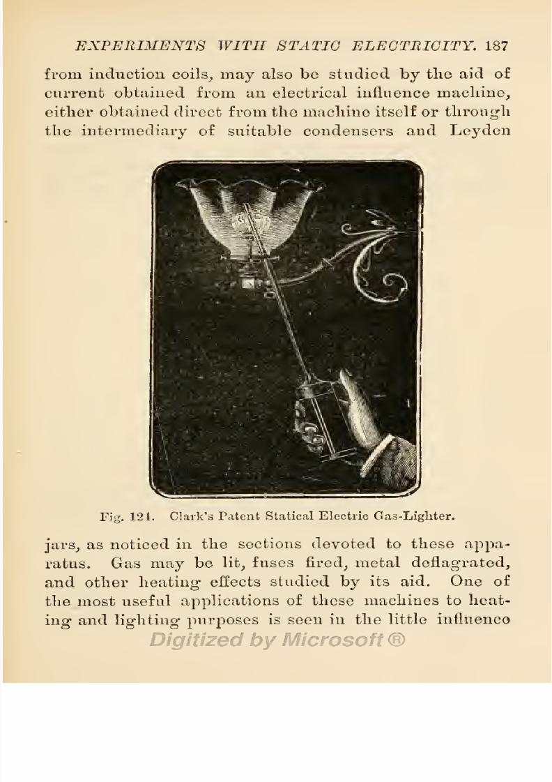
8/20/2019 electrical experiment.pdf
http://slidepdf.com/reader/full/electrical-experimentpdf 205/325

8/20/2019 electrical experiment.pdf
http://slidepdf.com/reader/full/electrical-experimentpdf 206/325
188
ELECTRICAL
EXPERIMENTS.
machines
known
as
Clark's
Patent
Electric
Gas-Lighter,
shown
in
action
at
Fig.
124.
In
this
little
machine,
a
high-tension
current
of
electricity
is
generated
by
the
influence
of
a
revolving
ebonite
cylinder
set
in
motion
by
a
ratchet
arrangement,
actuated
by pressing
a button
with
the
thumb,
as shown
in
the
illustration.
The
current
is
conveyed
to
the
tip
of
the
stem
by
insulated
Fig.
125.
Kinnersley's
Electric
Thermometer.
wires,
and
there
breaks
across
a
short
air
space
in
the
form
of
bright
sparks.
An
illustrated
description
of
the
interior
arrangements
of
this
machine
is
given
in
Gray's
Influence
Machines,
p.
195.
7.
Mechanical
Effects
of
Electric
Discharges.
These
differ
but
very
little
from
the
mechanical
effects
of
other
forces
discharged
at
high
pressure.
In
addition
to
those
already
noted
in
previous
sections
when
dealing

8/20/2019 electrical experiment.pdf
http://slidepdf.com/reader/full/electrical-experimentpdf 207/325
EXPERIMENTS
WITH
STATIC
ELECTRICITY.
189
with
the
discharge
from
Leyden jars,
we
may
now
notice
—
a.
Kinnersleifs
Electric
Thermometer,
which
is
shown
at
Fig. 125,
and was
supposed
to
indicate
a rise
in
tem-
perature
of
the
air in
the
larger
cylinder
by
the
passage
of the
electric
spark.
As a matter of
fact,
the
discharge
of
electricity
displaces
some of
the
air
in
the
inner
tube,
and
the
sudden
jerk
given
to
the surface
of
water
in
it
forces some
of the
water
into
the
outer
tube.
b.
The
Electric
Whirl,
shown
at
Fig. 126,
is
merely
a
pair
of
crossed
wires
with
their
tips
bent
at
nearly
right
Fig.
126. Electric Whirl.
Fig.
127.
The
Electric
Orrery.
angles
and
delicately poised
on
a
pivot.
When
this
is
placed
on the
prime
conductor
of
a
machine,
or
is
connected to
it,
the
positive
charge
is
given
off
to the
surrounding
air from
the
points
of
the
whirl,
and
this
striking
the
air
much the
same
as steam
or
water
issuing
from
a
pipe
at
high
pressure,
forces
the
whirl
around
at a
high
speed,
c.
A similar
result
is
obtained
by
a
different
cause
in
the
Electric
Orrery,
shown
at
Fig.
127,
This
instrument,
as
will
be seen
from
the
figure,
consists
of
an
arm
of
brass wire
with
a
knob
of brass
at
one
end,
and
another
arm
of
brass

8/20/2019 electrical experiment.pdf
http://slidepdf.com/reader/full/electrical-experimentpdf 208/325
190
ELECTRICAL
EXPERIMENTS.
wire
carrying
two
brass
knobs at
the
other
end. The
first
knob is
the
larger
and
heavier of
the
three.
The
main
arm
is bent
to
allow
the second arm free
play
as
it
turns
around
on
the
upturned
end on which
it is
nicely
poised.
The
whole is
delicately
poised
on a
sharp
point
mounted on
an
insulated
stand.
When
this
instrument
is
placed
under the
end
of the
prime
con-
ductor
of
an electrical
machine,
the
large
knob
becomes
positively
charged,
and
is
then
repelled
by
the
prime
conductor.
At
the
same
time the
second
knob
is
charged
similarly
to
the bend of the
arm
near
it,
and
is
also
repelled.
The
outermost
knob
is
at first
in a
negative
condition,
and
is thus attracted to the
prime
conductor,
but
on
approaching
it
the knob becomes
positively
charged,
when
it
is
repelled.
By
a
succession
of such
alternate
attractions
and
repulsions,
answering
to
a
series of
magnetic
reversals,
the
larger
ball
is
caused
to
revolve
on
its
pivot,
and
the other balls
revolve
more
rapidly
on
their
pivot,
thus
resembling
the motion
of
planetary
bodies,
d.
The
Electric
Seesaw
is
another
toy
illustrative
of
the
law
of
attraction
and
repulsion.
The
figures
of
two
boys
or
two
jockeys
are
carved
out
of
pith
and
nicely
painted,
then
glued
to
the ends
of
a
short
and
light
lath.
The centre
of this
is
glued
to
a
piece
of
brass
wire
sharpened
at
both
ends
to
form
pivots,
and
these are
mounted
in
sockets
pierced
in
two
brass
knobs cemented
to
the
tops
of
insulating
glass
pillars
secured
to
a base-board
of
polished
mahogany.
Two
brass
knobs
furnished
with
connecting-hooks
are
mounted
on
short
insulating
pillars
beneath
the
ends
of

8/20/2019 electrical experiment.pdf
http://slidepdf.com/reader/full/electrical-experimentpdf 209/325
EXPERIMENTS
WITH
STATIC
ELECTRICITY.
101
the lath
at both
ends
of
the
base-board. One of
these
must be connected
by
a
piece
of brass
chain
with
the
prime
conductor
of
the
machine,
whilst
the
other is
connected
by
similar
means
to
earth.
As
the
machine
is
worked,
the
pith figures
will
be
alternately
attracted
and
repelled,
and thus
execute
a see-saw
movement.
e.
The
Electrical
Swing
is
similarly
constructed,
only
in
this
the
pith
figure
swings
to
and
fro
between two
insulated
knobs,
on
a silken
swing
suspended
to
glass
pillars,
f.
Electric Dancers.
If
a
number
of
pith
balls
Fig.
128.
Apparatus
for Electric
Dancers.
be
strewn
on
a
metal
plate
and covered
with
a
belt
glass
receiver
having
a
Leyden
jar
knob
fixed
in the
top,
the
balls will
rise
to
the
knob
when
this
is connected
to
the
prime
conductor
of the
machine,
and
will
then
be
repelled
to
fall
on
the metal
plate.
If
this
plate
is
connected
to
earth,
a
brisk
interchange
of
opposite
charges
will
take
place
and
keep
the
pith
balls
in
a
state
of
continuous
commotion.
If,
now,
two
metal
plates
are
provided,
as shown
in
Fig.
128,
and
a
number
of
grotesquely
carved
pith
figures
of men
and
women

8/20/2019 electrical experiment.pdf
http://slidepdf.com/reader/full/electrical-experimentpdf 210/325
192
ELECTRICAL
EXPERIMENTS.
are
placed
on the lower
plate,
they
will
move
about
in a
similar
manner
and resemble
the
motions
of
a
dance.
a. Electrical
Insects.
By
the
exercise
of
a
little
in-
genuity,
figures
of
birds,
and
butterflies,
spiders,
etc.,
may
be carved
out
of
pith,
and
ornamented
by
light
fragments
of
feathers,
then
suspended
to
fibres
of
cocoon
silk
between
insulated
pillars
and
insulated
Fig.
129.
Electric
Chimes.
Pig.
130.
Dummy
Head
of
Hair.
plates,
to
swing,
flit,
and
fly
from
one
to
the other
as
they
become
alternately
charged
positively
and
nega-
tively,
h.
Electric
Chimes.
By
suspending
a
chime
of
small
bells
to
the
prime
conductor
of
a
machine,
as
shown
at
Fig.
129,
a
musical
variation
may
be
intro-
duced
into
the
entertainment,
as
the
little
brass
beads
swing
from
one
bell
to
another
under
the
influence
of
alternate
electric
charges.

8/20/2019 electrical experiment.pdf
http://slidepdf.com/reader/full/electrical-experimentpdf 211/325
EXPERIMENTS
WITH
STATIC ELECTRICITY. 193
There
are
several other
experiments
which
might
be
enumerated
to
illustrate the
mechanical effects
of
electric
discharges
from
an
electric
machine.
One
favourite
method
of
illustrating
electric
repulsion,
is
to
carve
a
figure
resembling
a
human
head,
and
stick
on it
some
real
long
hair.
This
hair
hangs
down
lank and
limp,
as shown
at
Fig.
130,
when the
figure
is un-
charged,
but rises
up
stiff as
if
the head
was
frightened,
when
it
is
charged
by
electricity
from
the
prime
con-
ductor of
the
machine.
That
the
discharge
causes
a
displacement
of
air
around
the
discharging point,
may
be
shown
by
holding
a
lighted
taper
to the
prime
con-
ductor whilst
the
machine is at work. The
flame
will
either
be
drawn
toward the machine
or
blown
violently
from
it,
according
as
the
movement
of
the
discharge
is
negative
or
positive.
8.
Physiological
Effects
of
Electric
Discharges.
The
effects of
discharges
from static electrical
apparatus
on
animal
tissues,
are
precisely
the same
as
those
from
other
generators
of
electricity.
For
instance,
if
we
have
a
Wimshurst
electrical
influence
machine,
and
wish to
test
the
physiological
effects
of its
discharge
on
ourselves,
we
first
withdraw the
wire from
between
the two
terminals
on
the stand between
the
Leyden
jars,
arrange
the
discharging
knobs
to
give
a
spark
of
only
j-inch,
then
connect
two
sponge
electrodes
by
wire
cords
to
the
two
terminals
of
the
machine.
On
holding
the wet
sponges
in the two
hands
whilst
a
friend
turns
the
machine
slowly,
a series
of
gentle
shocks
will
be
felt,
because
the
discharge
is delivered
at
o

8/20/2019 electrical experiment.pdf
http://slidepdf.com/reader/full/electrical-experimentpdf 212/325
194 ELECTRICAL
EXPERIMENTS.
a low
tension and
divided
between
the
body
and
the
discharging
knobs.
Now
increase
the distance between
the
discharging
knobs and turn
the
handle or
the
machine faster. The
intensity
of the shocks
will
be
increased
because
the
increased
speed
of the
machine
increases
the
tension of
the
current,
a
higher
resistance
exists
between
the
discharging
knobs,
and
more current
at
a
higher
tension is sent
through
the
body.
The
severity
of
the shocks
may
thus
be
increased,
much
the
same
as those
from
an
induction
coil,
and
become
in-
creasingly painful
with
each increase
of
tension
in
the
current
when
the
full
volume of this has
to
pass
through
any part
of the
body.
The
current from
static elec-
trical
apparatus may,
however,
be
divided
among
several
conductors,
much the
same as
that
from other
generators
or storers
of
electricity,
or
it
may
be
modi-
fied
by
resistances,
and
thus
the
severity
of
the shocks
be
mitigated.
When
the
body
is
placed
on an
insulated
stool
—
that
is,
a
stool
supported
on
glass
legs
(a
piece
of
wood
supported by
four
reversed
glass
tumblers
will
serve
the
purpose)
—
and
is
connected
with
the
prime
conductor of the
machine,
it
may
be
charged
with
electricity
much the
same as
any
other
condenser,
and
the
hair on it
will
stand
out
in
a state
of
mutual
re-
pulsion,
as
that
on
the
dummy
head
previously
men-
tioned.
When
a
person
is
thus
charged,
sparks
may
be
drawn
from
any
part
of
his
body,
or he
may
light
the
gas
by
pointing
his
finger
to the
burner.
A
very
in-
teresting
experiment
to
young people
may
now
be
per-
formed,
which
may
be named The
Electric
Kiss.
The

8/20/2019 electrical experiment.pdf
http://slidepdf.com/reader/full/electrical-experimentpdf 213/325

8/20/2019 electrical experiment.pdf
http://slidepdf.com/reader/full/electrical-experimentpdf 214/325
196
ELECTRICAL
EXPERIMENTS.
with vacuum tubes
appeared
in
the
Electrician,
vol.
xxvi.
;
and a
long
series of
letters on
Experiments
in
Electro-Statics,
many
of which are
very
interesting
1
,
may
be found
in
the
English
Mechanic,
vols.
lv.
and
Ivi.
Experiments
with electro-static
apparatus,
are
also
described
in
Mr. Perren
Maycock's
First
Book of
Electricity
and
Magnetism,
and
in
Mr.
Bottone's
book
on
the
same
subject,
both
published by
Messrs.
Whit-
taker &
Co.
8/20/2019 electrical experiment.pdf
http://slidepdf.com/reader/full/electrical-experimentpdf 215/325
CHAPTER V.
ELECTROLYTIC
EXPERIMENTS.
§ 52.
Electrolysis.
This
term,
means,
literally,
breaking
up by
electricity/'
and
was
first
employed by
Faraday
to
express
the
effects
of
an
electric current
on
water
when
passing through
it,
tho
effects,
as ob-
served
by
him,
being
a
breaking
up
of
water
into
two
separate
elements. Water is
composed
of the
two elemen-
tary
gases,
oxygen
and
hydrogen,
intimately
united
and
blended
by
chemical
affinity
to form a
liquid.
These
two elements
may
be
separated
by
passing
a
strong
current
of
electricity through
water,
when
this
liquid
is
said
to be
decomposed
by
electrolysis.
Water
is
thei-efore a
compound
body,
made
up
of
two other
bodies.
When
a
body
is
thus
compounded,
its
smallest
portion
—
that
is,
the smallest
part
into which
it
can be
divided
(in
water,
for
instance,
the
very
smallest
drop
or
particle)
—
is named
by
chemists
a
molecule,
and
this
molecule
is made
up
of
atoms,
each
atom
repre-
senting
a
separate
element. As water
is not
the
only
compound
substance
met
with,
the
other
compound
substances
may
be broken
up
by
electrolysis,
just
the
same
as
water is
electrolysed.
Some
compound
sub-
stances
may
be
electrolysed
whilst
in
a
state
of
fusion,
197

8/20/2019 electrical experiment.pdf
http://slidepdf.com/reader/full/electrical-experimentpdf 216/325
198
ELECTRICAL
EXPERIMENTS.
or
in
a
molten
condition at
a
high
temperature
;
but,
as
a
large
number
of
compound
substances
may
be
ren-
dered
soluble
in
water,
it
is
usual
to
employ
a
watery
solution
of them
for
electrolytic
purposes,
and
such
solutions
are
named
electrolytes.
In
the
experiments
about
to be
described,
the
electrolytes
will
be
watery
solutions of
compound
substances.
§
53.
Electric
Current
Required
for
Electrolysis.
Compound
substances
may
be
broken
up
and
their ele-
ments
separated
by
means
other
than
that of
electro-
lysis,
bat
it
is
clear
that
no
electrolytic
effects can
be
produced
without the
use
of an
electric
current.
Although
electric
action
accompanies
chemical
methods
of
decomposing compound
substances,
these methods are
not
generally
termed
electrolytic,
the latter
term
being
reserved
to
express decomposition
by
a
separate
electric
current.
The
electric current
required
to
electrolyse
a
compound
substance,
varies
with
the nature of
the
substance
under
consideration,
and is
determined
by
the
strength
of
the
bonds
of
chemical
affinity
binding
the
atoms
together
in
molecular
form. When
the
atoms
have
not a
very
strong
affinity, they may
be
separated
by
a feeble
electric
current.
Stronger
bonds will need
a
stronger
current to
break
them.
Almost
any
gene-
rator
of
electricity
may
be
employed
to
furnish electric
current
for
electrolytic
purposes,
the
principal
ex-
ception
being
those
machines
which
generate
alternating
currents of
equal
duration
—
that
is,
those
furnishing
a
current
in
one
direction,
and a current in the
opposite
direction
alternately
—
say,
for
illustration,
one
moment
8/20/2019 electrical experiment.pdf
http://slidepdf.com/reader/full/electrical-experimentpdf 217/325
ELECTROLYTIC
EXPERIMENTS.
199
negative
and
the
other
moment
positive.
Snch
currents
may
be
used
in
electric
lighting
and
for
some
other
purposes,
but not
for
electrolysis.
Electrolysis
of
liquids
may
be effected
by
irregular
currents,
such
as
those
from an iuduction
coil.
Although
these
are
somewhat
of
an
alternating
character,
the alternations
are
not
of
equal
duration
and
force,
as
we
have
already
seen in
dealing
with
them
for
experimental purposes.
Electrolysis
may
also
be
effected
by
current
from all
static
electrical machines
except
the
alternating
influence
machines.
The most
convenient
generator
of
current
for
this
purpose
is,
however,
a small
dynamo
electric
machine
driven
by
hand
power.
This,
for
small
and
short
experiments,
is handier
and
cleaner
than a
primary
battery.
If
required
for
longer
experiments,
it
should
be
driven
by
a
belt
from a
gas-engine,
oil-engine,
water-
motor,
model
steam-engine,
or
other
similar
source of
motive
power.
Small
dynamos
suitable
for this
purpose
are
described
and
illustrated
in
Mr.
Bottone's
books,
Electrical
Instrument
Making,
l
and
The
Dynamo
:
How
Made
and How
Used. Next to
dynamo
electric
machines,
may
be
classed
primary
batteries as
generators
of
current,
those
most
suitable
for
working
induction
coils
being
also
best
for this
purpose.
These are
fully
described
in
Induction
Coils/'
l
chapter
vi.
§
54.
Electrolysis
of
Water.
This
has
already
been
described,
under
the
head
of
Decomposition
of
Water,
in
§
29,
where
an
apparatus
for
use
with
induc-
tion
coils
has been noticed.
By
the
use of the
appara-
1
Published
by
Whittaker
&
Co.,
price
3s.

8/20/2019 electrical experiment.pdf
http://slidepdf.com/reader/full/electrical-experimentpdf 218/325
200
ELECTRICAL
EXPERIMENTS.
tus
illustrated
at
Fig.
132,
and a
constant current
having
an
E.M.F.
of
from
2
to
4
volts,
the
quantitative
and
qualitative
analysis
of
water
by
electrolysis
may
be
attempted.
The
apparatus
consists
of
a
mahogany
slab
on
which
rests a
glass
vessel with
two holes drilled
through
the
bottom
for
the
admission of
two
strips
of
platinum
connected to
the
two
binding
screws
seen
on
the
base
of
the
apparatus.
The
glass
vessel,
being
made
water-tight,
is
partly
filled
with
water
acidulated
Fig.
131.
U-Tube
Voltmeter.
Fig.
132.
Voltmeter
on
Stand.
with
a small
quantity
of
sulphuric
acid to
render
it
a
better
conductor,
because
water
itself
is a
bad
conduc-
tor
of
electricity.
Two
glass
test-tubes
partially
filled
with
some
acidulated water
are
now
inverted
over
the
platinum
strips,
as shown in section at
Fig.
133.
When
the
two
binding
screws
are connected
with
the
battery
or
other
source
of
electricity,
bubbles
will
be
seen
to
form
on
the
surfaces
of
both
platinum strips
and
pass
upward
through
the water
to
its
surface.
As the action
is
con-
tinued,
the water
in
both tubes will be
displaced
by
the
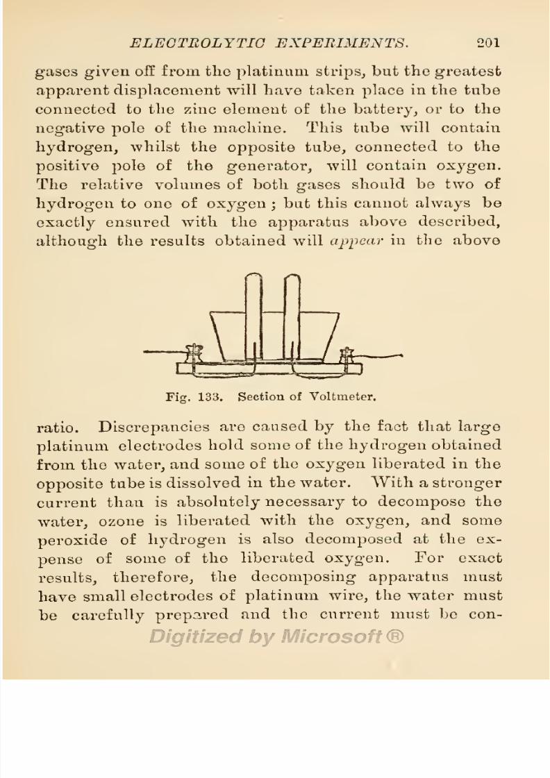
8/20/2019 electrical experiment.pdf
http://slidepdf.com/reader/full/electrical-experimentpdf 219/325
ELECTROLYTIC
EXPERIMENTS.
201
gases
given
off from the
platinum strips,
but the
greatest
apparent
displacement
will
have
taken
place
in
the
tube
connected
to
the
zinc
element
of
the
battery,
or
to
the
negative pole
of
the
machine.
This tube
will contain
hydrogen,
whilst
the
opposite
tube,
connected
to the
positive
pole
of the
generator,
will
contain
oxygen.
The
relative
volumes
of
both
gases
should
be
two of
hydrogen
to one
of
oxygen
;
but this
cannot
always
be
exactly
ensured
with
the
apparatus
above
described,
although
the
results
obtained
will
appear
in the
above
Fig.
133.
Section
of
Voltmeter.
ratio.
Discrepancies
are caused
by
the
fact that
large
platinum
electrodes
hold
some
of the
hydrogen
obtained
from
the
water,
and
some
of
the
oxygen
liberated
in
the
opposite
tube
is
dissolved
in
the water.
With
a
stronger
current
than
is
absolutely
necessary
to
decompose
the
water,
ozone
is
liberated
with the
oxygen,
and
some
peroxide
of
hydrogen
is
also
decomposed
at
the
ex-
pense
of
some
of
the
liberated
oxygen.
For
exact
results,
therefore,
the
decomposing
apparatus
must
have
small
electrodes
of
platinum
wire,
the
water must
be
carefully prepared
and the
current must be con-

8/20/2019 electrical experiment.pdf
http://slidepdf.com/reader/full/electrical-experimentpdf 220/325
202
ELECTRICAL
EXPERIMENTS.
trolled,
to
prevent
an excess of
ozone
being
formed.
The E.M.F.
of the
current
for exact results should
not
greatly
exceed
2
volts.
If the
two
platinum
wires
project
into one
tube,
the
water
in
that
tube
will
be
decomposed,
but
the
separated
gases
will
unite
again, forming
a
mixture
of
hydrogen
and
oxygen.
A
small
apparatus
for thus
decomposing
water,
and
showing
that
an
electric
current
is
gener-
ated
in
a chain
electric
belt,
is used
by
J.
Pulvermacher
& Co.
It
consists
of
a
small
test-tube
with two holes
drilled
through
the
bottom,
through
which two
thin
platinum
wires
are
inserted
at
distances
of
^-inch
apart,
sealed
in
position
by
sealing-wax.
The
interior ends of
these
wires
stand
up
in
the
tube to
the
length
of
i-inch,
and
the exterior ends
are soldered
to two thin
strips
of
brass for connection
with the
belt.
As the
resistance
is
very
small
in
acidulated
water
between
electrodes so
closely placed,
bubbles
of
gas
are
given
off from the
ends
of the
platinum
wires
when the links
of
a
belt
are
connected
to
them,
although
the
current
has.
only
an
E.M.F.
of 1-50 volts.
A
measuring
instrument
used
for
measuring
electric
force,
its construction
based on
the
discovery
by
Faraday
that
water
could bo
decomposed by
an
electric
current,
was invented
by
him,
and
named
(in
honour of
Volta)
the
voltameter,
or measurer
of
voltaic
electricity.
It
has been
found
that
the
quantity
of
hydrogen
given
off
from
the
negative pole
of
a
battery
in
a
given
time
is in
direct
ratio to
the
strength
of
current
passing
through
the acidulated
water
con-

8/20/2019 electrical experiment.pdf
http://slidepdf.com/reader/full/electrical-experimentpdf 221/325
ELECTROLYTIC
EXPERIMENTS.
203
tained
in
the
instrument.
The
equivalent quantity
of
oxygen
given
off from
the
opposite pole
is
also
governed
by
the
same
rule.
Now,
as
the quantity
of
electricity
passing through
a
resistance of one ohm
in one
second,
Avill liberate
'000158
grain
of
hydrogen,
and
one
grain
of
hydrogen
will
occupy
4673
cubic inches of
space,
the
volume of
current can be
easily
ascertained
by
noting
the
displacement
of
water
by
the liberated
hydrogen,
and
calculating
the
weight
of
the
hydrogen
by
the
foregoing
rule.
The
equivalent
weight
of
oxygen
liberated
from
the
opposite
pole
in
the
same
time
will
be
'001264
grain,
and
one
grain
of this
gas, owing
to
its
greater
density,
will
only
occupy
23*36
cubic
inches
of
space.
The voltameter
may
be constructed with
two
tubes
filled
with
acidulated
water,
inverted
over
platinum
electrodes
so
as to collect
and
measure the
gases sepa-
rately,
or
(and
this is the
usual
form)
the
two electrodes
may
be contained
in
one
glass
tube,
and
the
mixed
gases
measured.
The
tube
may
be etched
in
graduated
marks to show at
once
the
volume of
gas
liberated,
or
the
decomposition
may
be
effected in
a
separate glass
bottle
furnished
with an
air-tight
stopper
through
which
passes
a
bent
glass
tube
leading
to
a
glass
collector
in-
verted
in
a
trough
of
mercury,
and
marked
with
etched
graduations
to indicate
the volume
of
mixed
gas
liber-
ated
in
the
larger
vessel.
§
55.
Electrolysis
of
Coloured
Fluids.
Procure
a
glass
tube,
from 12 to
15
inches
in
length,
and
having
a bore of from
-f
to
1
inch.
Carefully
warm
it
in
the

8/20/2019 electrical experiment.pdf
http://slidepdf.com/reader/full/electrical-experimentpdf 222/325
204
ELECTRICAL EXPERIMENTS.
middle
by revolving
it
in
the
flame
of
a
Bunsen
burner,
hold
it
there
until
it
has
become red
hot,
then
bend
it
gradually
to
the
form
of
the
capital
letter
\J,
then
let it
cool
gradually
without
touching
any
cold
sub-
stance. When
cool,
cement the bent
part
in a
groove
cut
in a
heavy
slab of
mahogany
to
form
a
stand for
the
instrument.
This
is named
a
U-^ube,
and is
useful
for
electrolytic
experiments.
Tubes thus
bent,
mounted
and
furnished
with
a
pair
of
platinum
electrodes,
cost from 4s. to
5s. The
following
experiments
will
be
interesting.
r
1
Fig.
134.
Sectional
Elevation of a
U-Tube.
1.
Dissolve
^-oz.
of
sulphate
of
potash
in
clear
water,
and add
enough
tincture
of violets
to
render
the
liquid
a
beautiful
blue
tint.
Place
this
liquid
in
a
U-tube,
immerse
the
platinum
electrodes,
and
connect
them
to
a
source
of
electricity
giving
a
pressure
not
exceeding
2
volts.
The
current
from
a
Smee
cell will
be
most
suitable,
or
a
cell
made
of
a
glass
tumbler,
or
even
a
porcelain
cup
containing
a
copper
and
a
zinc
plate
immersed
in
acidulated
water.
As soon as the elec-
trodes
are connected
to the
battery,
the
liquid
in
the

8/20/2019 electrical experiment.pdf
http://slidepdf.com/reader/full/electrical-experimentpdf 223/325
ELECTROLYTIC
EXPERIMENTS.
205
limb
containing
the
positive
electrode
will
assume
a
red
tint,
whilst that in
the
opposite
limb
will
appear
green.
This
change
of
colour
is due to
decomposition
of
the
liquid
by
the
electric
current,
the
sulphate
of
potash
being
broken
up
into
its constituent
parts
of
sulphuric
acid
and
potassium.
Sulphuric
acid
is liberated
around
the
positive
pole,
and this reddens
the
tincture
of
violets,
whilst
potassium
is
determined
to
the
negative
pole,
and there unites with
hydrogen
to
form
potash,
and
this
gives
a
green
tint
to
the
solution.
If
the
battery
power
is
increased,
oxygen
will
be
given
off
from
the
positive
pole,
and
hydrogen
from
the
negative
pole.
2.
Procure
a
very
thin
and
dilute solution
of
starch
in
water,
and
dissolve
therein
a
few
grains
of
iodide
of
potassium.
Place this
in the
JJ-tube
and
connect the
electrodes
to
a
battery
as before
mentioned. Iodide of
starch
will
be
formed at the
positive
pole,
and
will
give
the solution
a
beautiful
purple
tint,
whilst
potassium
will
be
determined to
the
opposite
pole,
but
will
not affect
the
colour
of
the
solution.
3.
Repeat
the
experiment
with
common salt dissolved
in
water,
and
tinted
with
sulphate
of
indigo.
Chlorine
will
be
liberated
at
the
positive pole,
and this will
bleach
the
indigo
solution,
whilst the solution
in
the
opposite
limb is
unaffected.
4.
Repeat
the
experiment
with
nitrate
of
potash
dis-
solved
in
water and tinted with
tincture
of
litmus.
Nitric
acid
will be liberated at
the
positive
pole
and
tint
the
solution red in
one
limb,
whilst the other re-
mains
unaffected.
All
the
foregoing experiments
may
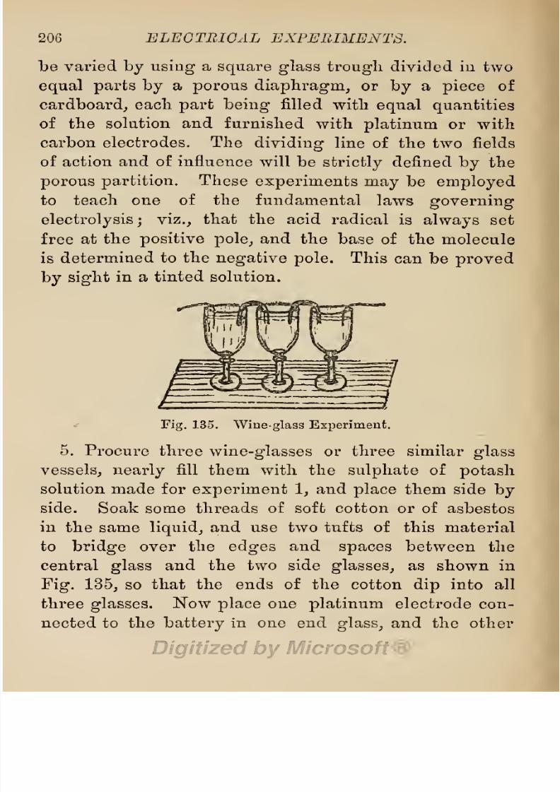
8/20/2019 electrical experiment.pdf
http://slidepdf.com/reader/full/electrical-experimentpdf 224/325
206
ELECTRICAL
EXPERIMENTS.
be varied
by
using
a
square
glass
trough
divided in two
equal
parts by
a
porous
diaphragm,
or
by
a
piece
of
cardboard,
each
part
being
filled
with
equal
quantities
of the solution
and
furnished with
platinum
or
with
carbon
electrodes.
The
dividing
line
of the
two
fields
of
action
and of
influence
will
be
strictly
defined
by
the
porous
partition.
These
experiments
may
be
employed
to
teach
one
of
the
fundamental
laws
governing
electrolysis;
viz.,
that
the acid
radical
is
always
set
free
at
the
positive pole,
and
the
base of
the
molecule
is
determined
to the
negative
pole.
This
can
be
proved
by
sight
in
a
tinted
solution.
Fig.
135.
Wineglass Experiment.
5.
Procure three
wine-glasses
or
three similar
glass
vessels,
nearly
fill them
with
the
sulphate
of
potash
solution
made
for
experiment
1,
and
place
them side
by
side.
Soak
some
threads
of soft
cotton
or
of
asbestos
in
the same
liquid,
and use two tufts of
this
material
to
bridge
over the
edges
and
spaces
between the
central
glass
and the two
side
glasses,
as shown in
Fig.
135,
so
that the
ends
of the
cotton
dip
into
all
three
glasses.
Now
place
one
platinum
electrode
con-
nected
to
the
battery
in one
end
glass,
and
the
other

8/20/2019 electrical experiment.pdf
http://slidepdf.com/reader/full/electrical-experimentpdf 225/325
ELECTROLYTIC
EXPERIMENTS.
207
electrode
in
the
other end
glass.
The current
from
the
Lattery
will
traverse the
whole sei'ies
of
glasses by
the
wet
threads,
and
the
results
shown
in
experiment
1
will
be
repeated,
the
liquid
in
one
glass
turning
red,
that in
the
opposite glass
assuming
a
green
tint,
whilst
that
in
the centre
glass
remains
unaffected. The
central
glass
may
be filled with
dilute
sulphuric
acid
by way
of
varying
the
experiment,
when of
course
it
will
be
colourless,
and
be
unaffected
by
the
action
going
on
in
the other
glasses.
Another
and
more
delicate
variation
may
be
adopted
by charging
the
glass
in which the
negative
electrode
is
immersed with
sulphate
of
soda,
the
centi'al
glass
with
dilute
sulphuric
acid,
and the
positive
end
glass
with
a solution of tincture of
violets,
then connect
the
whole
by
means of cotton
threads
dipped
in
the
sulphate
of soda
solution.
After
being
connected
to the
battery
for
a
short
time,
the
positive
glass
will
assume a
red
tint,
the
negative
a
green
tint,
whilst the
central
glass
remains
unchanged.
This
shows
that
the
moist
threads
of
cotton
act
as
syphons,
and
carry
over into
the
end
glasses
some
of the contents
of
the central
glass
when
an
electric
current
is
passing
through
them.
§
56.
Electrolysis
of
Metallic Salts.
When
an
electric
current
of
sufficient
strength
to
decompose
the
salts in
solution
is sent
through
a solution
of
metallic
salts,
the metal base of
the
molecules
is
deposited
on
the
negative
pole,
and the
acid
or
alkaline
radical is
set free
at the
positive
pole.
Thus,
if
we
make
a
solu-
tion
of
copper
sulphate,
the
metallic
salt
in
solution
is

8/20/2019 electrical experiment.pdf
http://slidepdf.com/reader/full/electrical-experimentpdf 226/325
208
ELECTRICAL
EXPERIMENTS.
composed
of
the
metal
base,
copper,
represented by
the
symbol
Cu,
and
the
radical,
sulphuric
acid,
represented
by
the
symbol
H
2
S
4
.
When
this salt
is
decomposed
by
the electric
current,
copper
is
deposited
on
the
negative
pole,
and
sulphuric
acid is
set free at
the
positive
pole.
If
the
positive pole
is
of
copper,
it
becomes oxidized
by
oxygen
set
free from
the solution
by
electrolysis,
and
the
radical
S
3
at
once
enters
into
combination
with
the
oxidized
copper
to
form
copper
sulphate.
If we
employ
a
solution
of a
metallic
chloride,
the metal is
deposited
on the
negative
pole,
and
chlorine
is
set
free
at
the
positive
pole.
If
we
employ
a
solution
of double
cyanide
of
gold,
silver,
or
copper,
the
radical
cyanogen
is
set
free
at
the
positive
pole
and
the
metal
at
the
negative
pole.
This
order is
always
observed
: the metal
is
always
deposited
on the
negative
pole,
and
that
which
enters into combination
with
the
metal
to
form
a
metallic
salt,
is
set
free
at
the
positive
pole.
The
positive pole
of an
electro-depositing
arrangement
is
named
an
anode,
from
Greek
words
meaning
the
way
into
or
down
into,
because
it
is the
way
by
which the
electric current
passes
from the
generator
doivn into
the solution
to be
electrolysed.
The
negative
pole
is named
a
cathode
or
kathode,
from Greek words
meaning
the
way up
or
the
way
out
of,
because it is
the
way
by
which
the
electric
current
passes
out
of
the
solution
back
to
the
generator.
Anodes
and
cathodes
must be
conductors of
the
electric
current,
and are
usually
in
the form of
plates
or
strips
of metal
suspended
in
the
solution
to
be
electrolysed.
Anodes
may
be

8/20/2019 electrical experiment.pdf
http://slidepdf.com/reader/full/electrical-experimentpdf 227/325
ELECTROLYTIC EXPERIMENTS.
209
insoluble
in
the
electrolyte,
as
when
platinum
is
em-
ployed
in a
solution
of
copper sulphate,
or
they may
be
soluble
in
the
solution,
as when
copper
is
employed
as
the
anode
in
this
solution.
Cathodes
may
be
of
the
same
metal
as
the
anodes,
or
an
entirely
different
metal,
but
they
must
not be
soluble
in the
electro-depositing
solution if
an
adherent
deposit
is
desired.
The
electro-
depositing
solution,
or the
solution
to
be
electrolysed,
is
named
an
electrolyte,
and
the
conducting
constituents
of
this
solution
are
named
ions
;
hence
those
which are
liberated
at
the
anode
are termed
anions,
and
those
at
the
cathode,
cations.
Metallic
salts
in
solution
may
be
decomposed
by
an electric
current,
but the
strength
of current
necessary
to effect
the
decomposition
will
vary
in
proportion
to
the
bond of
affinity
holding
the base to its
radical,
and
the
affinity
of this for
any
other
base introduced
into
the
solution.
When the bond of
affinity
is so
weak
as
to
allow
of
decomposition by
the
immersion of
another
metal
us
the
solution,
the
deposit
of
metal
from
the
solution is
said
to
be
effected
by
simple
immersion,
and is
simply
brought
about
by
chemical
action
in an
interchange
of
elements.
A
list
of
experiments
performed
by
Mr.
George
Gore
with
various
metals
in various
solutions,
to find those effected
by simple
immersion,
have
been
published
in his
book
on
Electro-Metallurgy,
and a
tabular
list
of
similar
experiments
may
be
found
in
the
Electro-plater's
Handbook,
at
p.
9,
§
12.
§
57.
Simple
Electro-Deposition
of
Metals.
When
two
metals
are
immersed
in
a metallic
solution
capable
p

8/20/2019 electrical experiment.pdf
http://slidepdf.com/reader/full/electrical-experimentpdf 228/325
210
ELEGTEIGAL
EXPERIMENTS.
of
dissolving
one
of
the
metals,
and the
two
are
connected
by
a wire above the
solution,
an electric
current is
generated,
and
metal
is
deposited
from
the
solution
on
that metal
which
forms
the
electro-negative
element of
the
pair.
This
is
shown
by
the
following
experiments.
1.
Deposition of Copper.
Crush
|-oz.
of
copper
sul-
phate
(the
bluestone
of
commerce),
and
dissolve
it
in
i-pint
of
hot
water.
Allow
this
to
cool,
then
put
it
in
a
glass
tumbler.
If
we
immerse
a
rod of
iron,
steel,
or
zinc
in this
solution,
either
of
those
metals
will
be
coated
with
copper by simple
deposition
;
but
if
we
place
a
brass
rod
in
connection
with
zinc,
the brass
rod will
receive a
coat
of
copper,
although
brass
by
itself will
not
become
coated
in
this
solution.
If
also
we
employ
rods or
strips
of sheet
silver,
german
silver, tin,
or
platinum
connected to
an
opposite piece
of
iron
or
steel,
these
metals,
being
electro-negative
to iron and
steel
in this
solution,
will
receive a
coat of
copper
by
electro-deposition.
It
may
be noted
here,
however,
that
although
brass
is
electro-positive
to
platinum,
it is
not
sufficiently
so to cause
a
deposit
of
copper
on
platinum
when
both
are
immersed as
a
pair
in
a
sulphate
of
copper
solution.
If
oxide of
copper
is
dissolved in
liquor
ammonia,
zinc
will
deposit
copper
from
this
solution
on
platinum.
A
very
beautiful
experiment
can
be
performed
with
a
solution
of
the
acetate
or
the
sulphate
of
copper,
a
polished
silver
plate,
and a
rod
of
zinc.
If
a
drop
of
the
copper
solution is
placed
on
the
silver
plate
and
then
touched
with
the
point
of
the
zinc

8/20/2019 electrical experiment.pdf
http://slidepdf.com/reader/full/electrical-experimentpdf 229/325
ELECTROLYTIC
EXPERIMENTS.
211
rod,
a series
of
dark
and
light
rings
will
be
formed
around
the
point
of
contact,
and
produce
a
very
pretty
effect
on
the
silver
plate.
2.
Deposition
of
Silver.
Simple
deposition
of
silver
by
chemical
interchange,
occurs
when
copper,
or
zinc,
or
common
brass
is
immersed in
a
solution
of
silver
salts,
the radical
of
which
has
an
affinity
for
the
immersed
metal. For
instance,
as
the
radical
cyanogen
has
an
affinity
for
copper
and
zinc,
these
metals
become
coated
with
silver in
a
solution
of
the
double
cyanide
of
silver
and
potassium
(the
ordinary
plating
solution),
and
as
the
radical
N
3
has
an
affinity
for
copper,
zinc,
and
brass,
these
metals
become
coated
with
silver
in
a
solu-
tion of
silver
nitrate.
Some
very
pretty
experiments
in
silver
deposition
may
be
effected
by
means of
a
solution
of
silver
nitrate,
among
the
most
interesting
being
the
formation of
a
silver
tree
named
Arbor
Diance,OT
Tree
of
Diana.
The
following
methods
may
be
employed,
producing
as
many
variations
of
this
beautiful
experi-
ment, a.
Dissolve
a-oz.
crystallized
nitrate
of
silver in
1
pint
of
distilled
water
contained in
a
glass
globe
or
decanter,
and
suspend
in
it from
the
mouth
by
a
piece
of
copper
wire,
a
small
lump
of
zinc,
with
branches
of
copper
wire. Set
it
aside
in
a
corner
where it
will
be
free
from
disturbance,
as on
a
corner
bracket,
and
in
a
short
time the
wires
will
be
coated
with
beautiful
silver
moss.
b.
Procure
6
dwts. of
mercury
and
2
dwts. of
silver
filings,
and
rub
them
together
in
a
mortar.
Dissolve
5
dwts. of nitrate
of
silver
in
1
pint
of
distilled
water,
and
add
to
it
3
dwts.
of
mercury
dissolved
in
half
a
tea-

8/20/2019 electrical experiment.pdf
http://slidepdf.com/reader/full/electrical-experimentpdf 230/325
212
ELECTRICAL
EXPERIMENTS.
spoonful
of nitric
acid.
Now
add
the
mercury
and
silver
amalgam,
which
will
fall to
the
bottom
of
the
vessel,
and
form
the
basis
of
a
splendid arborescent
growth
of
silver
crystals,
c.
Into
a
dilute
solution of
silver
nitrate
as
prepared
for
experiment
a,
pour
i-oz.
mercury. Crystals
of
pure
silver
will be
precipitated
on
the
globules
of
mercury,
d.
Add
a small
quantity
of
nitrate of
mer-
cury
as
prepared
for
experiment
b
}
to
a
decanter
filled
with
dilute
silver
nitrate
solution,
e.
Immerse
clean
strips
of
copper
foil cut
and
twisted
into
fantastic
forms
of trees
in the nitrate
of
silver
solution.
Silver
crystals
will
rapidly
form
on
the
copper
and
produce
a
magic
arborescent
growth.
/.
Procure
a
plate
of
polished
copper,
and
trace
thereon
with
a
camel-hair
pencil
the
form
of
a
tree.
The
skeleton
will
be
rapidly
clothed
with
silver
leaves,
g.
Dissolve
15
grains
of
silver
nitrate
in
\
a
dram of distilled
water,
and
make
a
small
pool
with
it
on
a
piece
of
clean
window
glass
placed
level
on
a
table
or
shelf,
in
a
secluded
place
free
from
disturbance,
then
put
several
pieces
of
bright
copper
foil
with
their
ends
just
touching
the
pool
at
various
points,
and allow
the
whole to
rest
undisturbed
for
some
three
or
four hours.
At
the
end of
that
time,
the
spots
in contact
with
the
metal will be
coated
with
a
fine white
crystalline precipitate
of
pure
silver.
In all these
experiments,
the radical N
3
of
silver
nitrate
has
a
greater
affinity
for
the
other
metals
than
it
has for
silver,
and
therefore
leaves
it
to
combine
with
these
metals,
thus
setting
the
silver
free.
In
solutions of silver
nitrate,
and also in
cyanide
of

8/20/2019 electrical experiment.pdf
http://slidepdf.com/reader/full/electrical-experimentpdf 231/325
ELECTROLYTIC EXPERIMENTS. 213
silver-plating
solutions,
all
metals
electro-negative
to
copper
and
zinc,
become
coated
with
silver
when con-
nected
together
to
form
electro-negative
and
electro-
positive
pairs
respectively.
3.
Deposition
of
Lead.
With
a
dilute solution
of
lead
acetate
in
distilled
water,
some
beautiful arborescent
growths
(named
lead
trees)
may
be
produced
by
means
similar
to those detailed
at a
in
the
preceding
sub-section,
using
zinc and
brass
wire
only
as the foundation for
the
growth.
Zinc
will also
receive
a
coating
of lead
in
a
solution of
nitrate and
hyponitrate
of lead.
In
these
solutions
also,
metals
electro-negative
to
zinc receive
a
deposit
of lead when
connected
with zinc
to form
a
pair.
A
very
beautiful
experiment
with
a lead
salt,
and
a
special
decomposing apparatus,
may
be
performed
as
follows. Dissolve
2
ozs.
of
caustic
potash
in
1
quart
of
distilled
water,
then add
2
ozs.
of
litharge,
and
keep
the
mixture
at
boiling
point
for
half an
hour.
Allow
it
to
cool,
pour
off the clear
portion,
and make it
up
to
1
quart
with distilled
water.
Pour this
in
a
glass
vessel
and
immerse
in it
a
polished plate
of
german
silver as a
cathode,
and
a
platinum
wire
embedded
in
glass,
all
except
the
tip,
as
an
anode,
connected to
a source of
electricity
having
an
E.M.P
of
15
volts,
which
will
be
represented by eight
Bunsen
cells
in
series.
The
anode
should
be
placed
with
its
point
close to
the
polished
plate,
and
the
beautiful
results
watched.
If
the
ar-
rangement
of
anode
and
current
are
suitable,
the
lead
salt will
be
decomposed
into metallic lead and
the
per-
8/20/2019 electrical experiment.pdf
http://slidepdf.com/reader/full/electrical-experimentpdf 232/325
214
ELECTRICAL
EXPERIMENTS.
oxide
of
lead,
and
both
will be
deposited
in
many-
coloured
iridescent
rings
on
the
polished
plate,
the
richest
colours
of
the
rainbow being
represented.
These
rings
are
known
as
Nobili's
rings,
from
the
name of
their
discoverer.
If the
current
is
too
strong,
only
brown
patches
are
deposited.
4.
Deposition of
Bismuth.
A beautiful
precipitate
of
metallic bismuth
may
be obtained
from
a
solution
of
20
grains
of nitrate
of
bismuth
in
a
wine-glassful
of
dis-
tilled
water,
by immersing
therein
a
strip
or
rod of
bright
copper.
Zinc,
tin, lead,
and iron
will
deposit
bismuth
on themselves
in a solution of chloride
of bismuth
;
and
brass
in contact with
zinc,
copper
in
contact
with
tin,
or
german
silver
in
contact
with
iron,
all receive
a
deposit
of
bismuth
in
this
solution.
5.
Deposition
of
Mercury.
With
a
solution
of
mercury
in
nitric
acid,
and
also with
salts
of
mercury
combined
with
chalk to
form a
paste,
some
experiments
may
be
performed
which savour
of
the
pretensions
of alchemists.
By dipping
an
iron
nail
into
a
solution of
copper sulphate,
it
will
become
coated
with
copper,
and
this
may
be
made
to assume
the
appearance
of
silver
by
dipping
the
copper-coated
nail into
a
solution
of
nitrate
of
mercury.
Unscrupulous
itinerant
vendors
of
cheap
plate
powders,
frequently
deceive
the
uninitiated
and
gullible public,
by
rubbing
a
copper
or
brass
article
with
similar
mer-
cury-charged
powders and
pretending
that
these deposit
a
coat of
pure
silver
on the
article
Mercurous
salts
yield
metallic
mercury
to
antimony,
bismuth,
cadmium,
copper,
iron, lead,
tin,
zinc, brass,
and
alloys
of
silver

8/20/2019 electrical experiment.pdf
http://slidepdf.com/reader/full/electrical-experimentpdf 233/325
ELECTROLYTIC
EXPERIMENTS.
215
with these metals.
Nitrate of
mercury
will
yield
its
metal
to
antimony,
bismuth, brass,
cadmium,
copper,
iron,
lead,
and
zinc.
In
a
solution
of
this
salt,
silver
will
receive
a
deposit
of
mercury
when
connected
to
zinc or
iron,
and
platinum
when connected
to
copper.
6.
Deposition
of
Iron.
In
a
saturated
solution
of the
protosulphate
of
iron,
platinum
will
receive
a
deposit
of
iron when
connected
to
zinc.
7.
Deposition
of
Tin.
In
a
solution of
chloride
of
tin,
zinc and
lead
become
tinned,
and
antimony,
tin,
or
copper,
receive a
coating
of
tin
when
connected
to
zinc.
8.
Deposition
of
Nickel.
In
a
solution
of
the
double
chloride
of
nickel and
ammonium,
copper
connected
to
zinc will
receive
a
coating
of
nickel.
9.
Deposition
of
Platinum.
In a
solution of
tetra-
chloride
of
platinum,
the
metal
is
deposited
on
platinum
connected
to
zinc.
10.
Deposition
of
Gold.
In a solution
of
terchloride of
gold,
all
metals
electro-positive
to
gold deposit
this
metal on themselves.
In
a
solution of double
cyanide
of
gold
and
potassium,
copper,
brass,
german
silver,
and
zinc will
coat
themselves
with
gold,
and
all
metals
elec-
tro-negative
to
zinc
when
connected
to this
metal.
§58.
Single-Cell
Electro-Deposition
of Metals.
When
two
metals are connected
together
in
two
separate
solu-
tions
separated
by
a
porous
division,
and
metal is electro-
deposited
on the
electro-negative
metal of the
pair,
the
process
is named
the
single-cell
process
of
electro-
deposition. By
this
process
some
beautiful works of
art
have
been
produced
in
electro-deposited
copper,
and
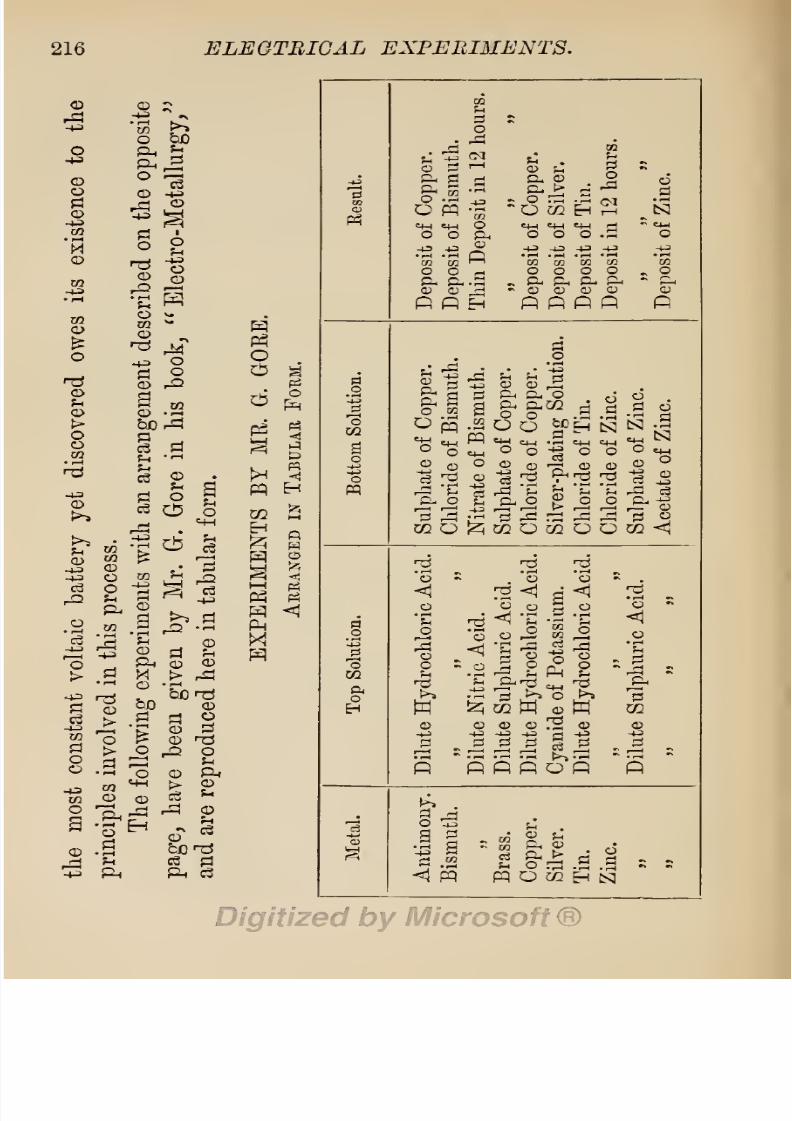
8/20/2019 electrical experiment.pdf
http://slidepdf.com/reader/full/electrical-experimentpdf 234/325
216
ELEGTBIGAL
EXPERIMENTS.
©
8/20/2019 electrical experiment.pdf
http://slidepdf.com/reader/full/electrical-experimentpdf 235/325
ELECTROLYTIC
EXPERIMENTS.
217
It
is
possible
in some
cases
to
dispense
entirely
with
a
porous partition
when
conducting experiments,
the
two
liquids
being
separated
by
the difference
in
their
specific gravity,
the heavier
liquid
being
poured
into
a
tall
glass
first,
and
the
lighter liquid
so
introduced
as
to
float above
the
first.
This
may
be done
by
floating
a cardboard
disc
on
the
first
liquid,
then
pouring
the
second
carefully
on this.
When
thus
arranged,
we
may
witness
the
interesting
experiment
of
one
metal
being
dissolved
by
the
upper layer
of
liquid
whilst
the
lower
part
of
the
same
rod is
receiving
a
deposit.
The
results
of
such
an
arrangement
in some
experiments
performed
by
Mr.
Gore,
are
shown
in
tabular
form on
the
opposite
page.
If
we
employ
a
glass
trough
divided
into
two
equal
compartments
by
a
partition
of
porous
earthenware
cemented
to
the
sides
of the
glass
vessel,
the
range
of
experiments
may
be
extended to
such
metals
as
gold
and
platinum,
on
which
a
deposit
of the
baser
metals
may
be
obtained
when
one
end of a bent rod of
gold
or
of
platinum
is
made
to
dip
into
a
solvent
solution on
one
side and
a
strong
solution
of
the
base
metal
on the
other
side
of the
partition.
Cyanide
of
potassium
is a
solvent
for
gold,
and
aqua
regia
a
solvent
for
platinum.
The
process
of
electro-deposition
known as
the
single-
cell
process,
is,
however,
carried
on
generally
by
means
of
a
compound
cell
consisting
of
a
large
containing
outer
cell
holding
the
solution
of
the
metal
to
be
de-
posited,
and
an
inner
cell
of
porous
earthenware
hold-
ing
the
solvent
solution
and
the
metal
to
be
dissolved

8/20/2019 electrical experiment.pdf
http://slidepdf.com/reader/full/electrical-experimentpdf 236/325
218
ELECTRICAL
EXPERIMENTS.
to
furnish
the
electric
current.
In this
arrangement
the
two
liquids
touch each
other
through
the
pores
of
the
cell,
but
do
not
mix,
and the two
metals
are
con-
nected
by
a
wire above
the
liquid,
and
thus
complete
the circuit.
The
cells of
the
battery
known
as
the
Daniell
battery,
invented
by
Professor
Daniell,
are
thus constructed.
In the
original
arrangement
the outer
cell
was
con-
structed
of
copper,
but
in
the
modern
modifications
of
his
invention,
the
outer
cell
may
be
of
stoneware,
porcelain,
or
glass,
and the
negative
element
(copper)
contained
therein
be of
any
form,
either
a
cylinder
surrounding
the
porous pot,
a
plate,
or
a
rod,
as
may
suit
the
convenience
of
the
maker. It
is
best,
however,
to
have
a
large
negative
surface,
and therefore
a
cylinder
of
copper
makes
the best
negative
element.
This
must be
immersed
in
a
saturated solution
of
copper
sulphate,
and
provision
must be
made to
keep
the
solution
in
a
saturated
condition
by
suspending
therein
a
bag
containing
crystals
of
the
copper
salt,
which
dissolve
gradually
and so
maintain
the
density
of
the
solution.
The
positive
element
(zinc)
is
con-
tained
in
a
cell
of
porous
earthenware
immersed
in
the
copper
solution.
This
cell
is
charged
with dilute sul-
phuric
acid,
which
enters
into combination
with the
zinc, forming
zinc
sulphate,
and
furnishing,
when the
two
elements
are
connected,
a current
of
electricity,
having
a
potential
of
a
trifle over
one volt.
As
this
force
is
quite
enough
to
decompose
a
solution
of
copper
sulphate,
it
not
only
deposits
copper
on
the
negative

8/20/2019 electrical experiment.pdf
http://slidepdf.com/reader/full/electrical-experimentpdf 237/325
ELECTROLYTIC
EXPERIMENTS.
219
element
of the
battery,
but also furnishes
enough
current
to
decompose
a
solution of this
salt
in
a
separate
vessel.
As
this
force
will also
decompose
gold
and
silver
solutions,
and is constant for
long
periods,
the
Dauiell
battery
is esteemed
one of the
best
generators
of
electricity
for the
purposes
of electro-
deposition.
§
59.
Electrotype
Experiments.
If
we
remove
the
copper
plate
or
cylinder
of
a
Dauiell
cell,
and substi-
tute
a
copper
coin,
brass
medal,
or other
metal
article
connected
to
the
zinc,
it
will
(provided
it
is
electro-
negative
to
zinc)
be
coated with a
deposit
of
copper.
If the
coin
is
soiled with
grease,
oil,
or
other animal
substance
before
being placed
in
the
solution,
the
de-
posit
of
copper
will
not
adhere
firmly
to
the
coin,
but
may
be
peeled
off when
it
has
attained the thickness of
paper.
The
inside
portion
of
this
envelope
will
then
be found
to
have
taken
an
exact
impression
in
reverse
of
the
features
of
the coin
which
it
covered. The
dis-
covery
of
this
fact
by
Mr.
Spencer
in
1836
led to the
invention
of
the
electrotype
process
of
duplicating
de-
signs
in
copper.
By
this
process
any
artistic
design
cut,
or
engraved,
or
stamped,
or
cast on
any
metal,
or
other
substance,
may
be
exactly
reproduced
in
the most
minute
detail
in
copper.
It has
received
the
name of
electrotype,
because
a forme of
printing
type may
be
exactly
copied,
and
the
copy
used
instead
of
the
original
for
printing
the
book.
Although
the
process
may
be
put
to
such
uses,
it
is
rarely
if
ever
thus
employed
at
the
present
day,
as
it is more
costly
than
the
equally
8/20/2019 electrical experiment.pdf
http://slidepdf.com/reader/full/electrical-experimentpdf 238/325
220
ELECTRICAL
EXPERIMENTS.
effective
stereotype
process
of
duplicating
formes of
printing type.
The chief
employment
has been
in
the
duplication
of
engravings,
for
which
it is
eminently
suitable.
The
engraved
wood
block,
or
other
design
to
be
copied,
is first
reproduced
in
wax
or
in
gutta-percha,
or
a similar
plastic
material which
will
take the
fine
lines of
the
engraving,
and
this
copy
is
then
carefully
coated
with
blacklead
to
render
its
surface
capable
of
conducting
the electric
current and
receiving
a coat
of
copper.
Copper
is then
electro-deposited
on
this
mould
until
the
film
of
metal
is
deemed
to be
thick
enough,
when it is removed
and
backed
with
type
metal,
and
mounted
on a
type-high
wooden block
for
the
printing-
press.
As
some
experiments
illustrative
of
this
process
will
be found of some
interest,
I
give
a
few
directions for
their
performance.
1.
Electrotype of
a Medal
or
Coin. Valuable
coins,
however
old,
may
be
exactly
duplicated
in
copper
by
the
electrotype process.
For
coin
cabinets,
where
it
is
desirable to
keep
the
valuable
coins under
glass
to
pre-
serve them from the
fingers
of
connoisseurs,
and
yet
show
them both on
the obverse
and
reverse
side,
this
method of
duplication
has
several
advantages.
Copies
of
both
sides
can be
taken
and backed to
the
required
thickness,
then cemented
by
their
backs
to
the
case
under
the
glass,
and thus be shown
to
friends
side
by
side
with
the real
coin.
If
the
coins
are
of silver
or
of
gold,
the
appearance
of
the
original
may
be
reproduced
by
gilding
or
silvering,
directions
for
doing
this
being

8/20/2019 electrical experiment.pdf
http://slidepdf.com/reader/full/electrical-experimentpdf 239/325
ELECTROLYTIC
EXPERIMENTS.
221
given
further
on.
The mould
for
duplicating
coins,
may
be
made
of
wax,
of
gutta-percha,
of
plaster
of
Paris,
or
of
fusible
metal.
a. To make
a
mould
of
gutta-percha,
heat
some of
this
material
in
scalding
hot
water
until
soft,
roll
it
into
a
ball,
press
the
ball
on
the
centre
of
the
coin,
and
work it with the
finger
and
thumb
until
it
forms
a
cake
all
over
the
coin
and down
over
the
edges,
then
put
the
coin
on
a
bench,
and a
piece
of
metal
heavily
weighted
on
the
gutta-percha
at
the
back. Allow
this to
get
quite
cold
and hard
before
removing
the
weights,
b.
To take a mould
in
wax,
get
some
good
beeswax
and
soften
it
by
heat
(and
by
working
in the
warm
hand)
until
it
is
soft
enough
to
be worked over
the
coin,
as
with
the
ball of
gutta-percha,
then
set aside
to cool
and
harden.
It is
advisable
to
lightly
oil the
coin
before
pressing
on
the
gutta-percha
or
wax,
to
prevent
these
substances
from
sticking
to
the coins, c.
To
take
a
mould
in
plaster
of
Paris,
get
a
cardboard
tray
large
enough
to
hold the
coin,
and some
good
plaster
of
Paris. Oil the
coin
and
place
it
in
the
box.
Mix some
plaster
of
Pai'is
with
water
to
the
consistency
of
cream,
and
pour
it in
the
box
on the
coin,
stirring
all
the
time
with
a feather
to
break
up
air-bubbles,
then
set aside
to harden. When
quite
hard,
remove
the
coin
and
gently dry
the
mould
for
several hours.
When
the
mould
is
dry,
bake
it
in
an
oven,
and
dip
it
whilst
hot
in
linseed
oil,
then
set
aside for the oil
to
oxidize
and
harden.
The
mould should be
treated
two
or
three
times
like
this,
so as
to
get
the
oil well
into the
plaster,

8/20/2019 electrical experiment.pdf
http://slidepdf.com/reader/full/electrical-experimentpdf 240/325
222
ELECTRICAL
EXPERIMENTS.
and thus
prevent
it
from
absorbing
water,
d.
Fusible
alloy,
fusible
metal,
or
clichee
;
'
as it
is
sometimes
named,
is
an
alloy
of
tin,
lead,
and
bismuth
in
the
following proportions
:
—
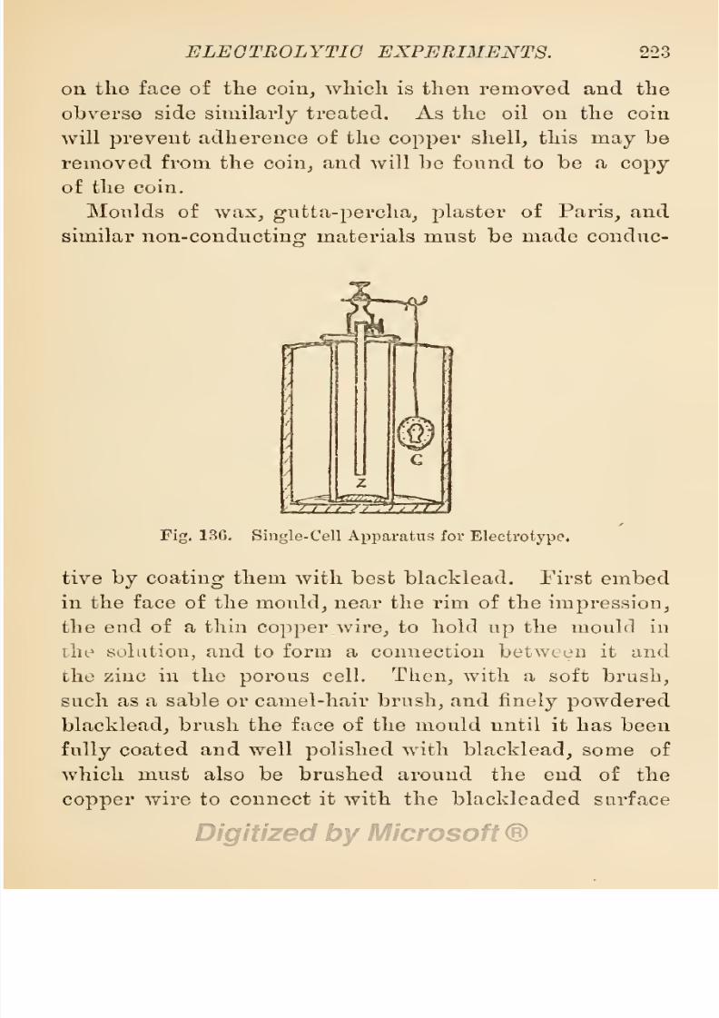
8/20/2019 electrical experiment.pdf
http://slidepdf.com/reader/full/electrical-experimentpdf 241/325
ELECTROLYTIC
EXPERIMENTS.
223
on
the
face
of
the
coin,
which is
then removed
and
the
obverse
side
similarly
treated.
As the oil on the coin
will
prevent
adherence of
the
copper
shell,
this
may
be
removed
from the
coin,
and
will
be found
to
be
a
copy
of
the
coin.
Moulds of
wax,
gutta-percha, plaster
of
Paris,
and
similar
non-conducting
materials must
be
made
conduc-
Fig.
13G.
Single-Cell
Apparatus
for
Electrotype.
tive
by
coating
them
with
best blacklead. First
embed
in the face of
the
mould,
near
the rim of the
impression,
the end
of
a thin
copper
wire,
to hold
up
the
mould
in
be
solution,
and
to
form
a
connection between it and
the
zinc in the
porous
cell.
Then,
with
a
soft
brush,
such
as
a
sable or camel-hair
brush,
and
finely powdered
blacklead,
brush
the
face
of the
mould
until
it
has
been
fully
coated
and
well
polished
with
blacklead,
some
of
which
must
also be
brushed
around the end
of
the
copper
wire to
connect it
with
the
blackleaded surface

8/20/2019 electrical experiment.pdf
http://slidepdf.com/reader/full/electrical-experimentpdf 242/325
224
ELECTRICAL
EXPERIMENTS.
of
the
mould.
The
mould
should
then
be
weighted
with
a
scrap
of
lead to
sink
it
in
the
copper
solution,
and
suspended
in
the
outer
cell
connected
to
the
zinc
of
the
inner
cell
of
a
Daniell
battery,
as
shown
at
Fig.
136.
After
several
hours,
the
shell
of
copper
will
be
thick
enough
to
be
separated
from
the
mould.
This
must
be
carefully
done
if the
mould is
to
be
used
again,
the
edges
of
the
shell
being
raised
all
around
with
a
thin
knife
before
separating
it from
the
mould.
The
back
of
the
shell
must
then
be
cleaned
from
bits
of
wax,
etc.,
and
brushed
with
soldering
fluid,
then
coated
with
solder
to
give
the
shell
a
necessary
stiffness,
and
the
ragged
edges
sheared
off
with
a
pair
of
stout
sharp
scissors.
This
done,
some
molten
solder
may
be
poured
in
the
shell
to
fill
it
up
to
the
thickness
of
the
original
coin,
or
it
may
be
filled
up
with
type-metal
to
the
necessary
thickness.
This
backing
should
be next
levelled
with
a coarse
file,
and
a
thin
disc
of
copper,
furnished
with
a
loop,
soldered
to
the
back.
Any
medal,
seal,
engraved
or
stamped
surface
of
metal
or
other
material,
may
be
copied
in a
similar
manner
if
the
design
is not
undercut,
and
is
free
from
projecting
or
overhanging
parts.
2.
Electrotypes of
Fishes,
Ferns,
and Leaves.
Small
fish
such
as
minnows,
whitebait,
and
sprats,
maybe
copied
in
copper
by
a
similar process,
and
then
silver-plated
to
form
brooches,
ornaments
for
the
hair,
and other
orna-
mental
purposes.
To take
a
mould of
a
fish,
half
fill
a
shallow
cardboard
box
with
fine
sand,
and
bed
one-half

8/20/2019 electrical experiment.pdf
http://slidepdf.com/reader/full/electrical-experimentpdf 243/325
ELECTROLYTIC
EXPERIMENTS.
225
of
one
side of
the
fish in
the
sand,
leaving
the
upper
half clean
and
clear. Next
get
some
good plaster
of
Paris,
and
some clean water
in
a
basin,
stir
the
plaster
into
the
water
in small
quantities
until
a
mixture is
made
of
the
consistency
of
thin
cream,
then
pour
this
at
once
into the
box
on
the
fish,
whilst
stirring
with a feather
to
break
air-bubbles.
When
this
cake
of
plaster
is
dry,
carefully
turn
it,
with
the fish
and
the
sand,
out of
the
box,
trim the
plaster carefully
with
a
sharp
knife
around
the
fish,
then
replace
the
whole
in
the
box,
with the
fish
uppermost.
Next
get
a
piece
of
tissue
paper
and cut a
hole
in
the centre
to
the
shape
of the fish
and
lay
this
in the
box,
surrounding
the
fish,
and
shielding
the
plaster
cast
from
contact
with
the
wet
plaster
about
to
be
poured
on
it in
the box.
A
plaster
mixture
is
next
prepared
as at
first,
and
poured
on
the
fish
until
the box
is
filled.
When
this
has
set
hard,
the
whole
may
be
turned out of the
box
and
the two
moulds
easily parted,
as the tissue
paper
will
have
pre-
vented
adherence
of
the
plaster
to
the
plaster
cast.
The
fish
may
now be taken
out
and
the
moulds dried
and
prepared
as directed
at c
in
the
previous
sub-section.
The
conducting
wires
from these
moulds should
pass
around
the
edges,
and
the
blacklead
be
spread
to
meet
the
wire on
all
sides. On
suspending
the moulds in the
solution,
care
must
be
taken
to
brush
off
with
a
feather
all the
bubbles
which form on the
surfaces.
The two
halves
of
the
copper
fish
must be
backed
with
solder,
then
trimmed
and soldered
together.
Ferns
and leaves
are
best
copied
by
taking
moulds of

8/20/2019 electrical experiment.pdf
http://slidepdf.com/reader/full/electrical-experimentpdf 244/325
29,f
ELECTRICAL EXPERIMENTS.
them
in
wax.
This
is
done
by
brushing
the leaf
or
fern with
hot
beeswax,
allowing
the
layer
to
cool,
then
adding
another
layer,
and
so
on
until
a
sufficiently
thick
cake
of
wax has been
laid
on
the leaf to
form
a mould.
The leaf is
then
carefully
removed
from the cold
wax
and
the
impression
coated with
blacklead
in the usual
Fig.
137.
Electrotyping
Apparatus.
manner
to
render
it
conductive.
Copies
may
be
taken
in
plaster
of
Paris,
the
leaf
or
fern
being
backed
by
sand
in
a
box,
and
plaster
poured
on
the
leaf
as
for
copying
coins;
but
this
process
does
not
so well
preserve
the
natural
features
of the
leaf.
3.
Electrotypes
of
Stamped
or
Engraved
Surfaces.

8/20/2019 electrical experiment.pdf
http://slidepdf.com/reader/full/electrical-experimentpdf 245/325
ELECTROLYTIC
EXPERIMENTS.
227
These
are
produced
in
the
same
way
as
those
of
coins
and
medals,
the
moulding
material
generally
used,
being
best
yellow
beeswax.
The
engraved
wood
block,
stamped
metal
design,
or
forme
of
printing
type,
is
placed
in
a
suitable
frame
with
raised
sides
to
prevent
the
wax
from
flowing
off
from
the
surface,
and
melted
wax
is
poured
into
the
frame
until a
cake
of
the
requi-
site
thickness has
been
obtained
on
the
surface to
be
copied.
When
this
is
quite
cold,
it
is
separated
from
the
original,
furnished
with
conducting
wires,
and
coated
with
blacklead,
then
immersed in
a
suitable
depositing
solution,
connected
to
a
separate
source of
electric
power
such
as a
battery
or a
dynamo.
This
class
of
work
cannot
be well
done
by
the
single-cell
process,
and
therefore
rightly
belongs
to
the
class
mentioned
in
the
next
section.
When
a
shell
of
the
requisite
thickness
has
been
obtained,
it is
backed
with
solder and
with
type-metal
to
form
a
rigid
plate,
which
is
then
secured
by
brads
to a
type-high
slab
of
beech,
mahogany,
or
oak.
§
60.
Electro-Deposition
of
Metals.
If
while
con-
ducting
the
single-cell
processes
mentioned in
the
pre-
vious
section,
we
connect the
zinc in
the
porous
cell
with
one
stud
of
a
galvanometer,
and
the
mould
in
the
copper
solution
with
the
other
stud
of
the
instrument,
the
needle will
be
at
once
deflected,
and
thus
show
that
an
electric
current
is
passing
from
the
copper
to
the
zinc
outside
the solution.
The
sine-le-cell
arrange-
ment is
therefore a
cell
of
an
electric
battery,
and
will
furnish
power
outside itself.
This
may
be
proved
by

8/20/2019 electrical experiment.pdf
http://slidepdf.com/reader/full/electrical-experimentpdf 246/325

8/20/2019 electrical experiment.pdf
http://slidepdf.com/reader/full/electrical-experimentpdf 247/325

8/20/2019 electrical experiment.pdf
http://slidepdf.com/reader/full/electrical-experimentpdf 248/325
230 ELECTRICAL
EXPERIMENTS.
should
now
be at
the bottom of
the
glass
vessel
a
quantity
of
white
curds,
which
is
cyanide
of
silver.
Allow
this to
settle
down,
then
carefully
pour
off
the
jiquid
and
pour
a
quantity
of
fresh water
on the
pre-
cipitate,
pour
off
this
and
repeat
the
operation
two
or
three
times
to
thoroughly
wash
the silver
cyanide.
Then
pour
in
the
remainder
of
the
potassium cyanide
solution,
which
will
dissolve the
cyanide
of
silver and
form
the
double
cyanide
of
silver-plating
solution.
Dilute
this
with
distilled
water
to
make one
pint
of
solution,
and work
it
with an
anode
of
pure
silver,
and one
or
two
cells of a Daniell
or
Smee
battery.
Coins
and
medals
to
be
silver-plated,
must be
freed
from
all
dirt and
corrosion
by
boiling
them
in
strong
soda
water,
then
brushed
with
pumice
and
water
or
with
finely powdered
bath
brick,
and
finally
rinsed
in
water
before
being
placed
in
the
plating
solution.
2.
Gilding
Solution.
Dissolve
4
dwts.
of
good
cyanide
of
potassium
in
1
pint
of distilled
water
contained
in
an
enamelled
iron
saucepan.
Make
this solution
scalding
hot,
but
not
boiling,
and
suspend
in
it
two
strips
of
pure
gold,
one
of
which
is
connected
to
the
zinc,
or
positive
element,
and
the
other to
the
copper,
or
negative
element
of a
battery
of
three
cells in series.
Pass a
current
from
one
piece
of
gold
to
the
other for
a
period
of
three
hours,
at
the
end
of
which time some
of
the
gold
will
have
dissolved
from
the
plate
con-
nected to
the
negative
element
and
have
entered
into
combination with
some
of
the
cyanide
in
solution to
form
the
double
cyanide
of
gold
and
potassium gilding

8/20/2019 electrical experiment.pdf
http://slidepdf.com/reader/full/electrical-experimentpdf 249/325
ELECTROLYTIC EXPERIMENTS.
231
solution. The two
strips may
then
be
suspended
from
the
negative
element
to
form
the
anode,
and
the
solu-
tion
may
be worked
by
one
cell of a
Daniell or
Smee
battery,
gold being freely
deposited
from
it,
when
made
hot,
on
silver
and
copper
coins.
The same
care must be
taken
in
cleaning
articles to be
gilded,
as
for
silver
plating.
3. Nickel
Solution.
To
make a
nickel-depositing
solution,
dissolve
2
ounces of
the
double
sulphate
of
nickel and
ammonium
salt
in 1
pint
of
hot
water,
then
strain
it
through
a
filter,
and
add,
when
cold,
about
a
teaspoonful
of
liquor
ammonia.
This
solution should
be
contained
in a
stone-ware,
porcelain,
or
glass
vessel,
and
worked
cold
with
at
least
4
cells
in
series
of
the
Daniell
or
Smee batteries.
Even
more
care must be
taken
in
cleaning
articles for
nickel-plating
than
for
silver-plating.
Amateurs
and
experimenters
who
may
wish to
carry
on these
experiments
without
having
the
trouble
of
making
solutions and
setting
up
a
battery, may
get
a
portable
set of
apparatus
for
the
purpose,
from Messrs.
•J.
E.
Hartley
&
Co.,
St.
Paul's
Square,
Birmingham.
Students
of the
science
will find
further
information
in
Gore's
Electro-Metallurgy,
Napier's
Electro-
Metallurgy,
Watt's
Electro-Deposition,
and in
the
Electro-plater's
Handbook.
1
1
Electro-plater's
Handbook,
price
3s.; Whittaker
&
Co.,
London.

8/20/2019 electrical experiment.pdf
http://slidepdf.com/reader/full/electrical-experimentpdf 250/325
CHAPTER VI.
MISCELLANEOUS
ELECTRICAL
EXPERIMENTS.
§
61.
Thermo-Electrical
Experiments.
If
bars of
two
such,
metals
as
bismuth and
zinc
are soldered
to-
gether
at one
end,
and
the two free ends are connected
to
the
binding
screws
of a
delicate
galvanometer,
the
needle
of
this
instrument
will
be
deflected
when
the
junction
of
the two
metals is
warmed
by
the flame of
a
spirit
lamp.
This
property
of metals
was
discovered
by
Professor Seebeck
of
Berlin
in
1821,
and has
since
received
close
attention
from
such
able
men
as
Mat-
thiessen,
Kohlrausch,
Becquerel,
Neumann,
Wheatstone,
Svanberg,
Nobili,
Clamond,
Melloni,
Poullet,
and
Peltier.
The
phenomena
of
thermo-electricity
has
therefore been
fully investigated,
and
the results
reduced
to
an
exact
science.
The researches of
Dr.
Matthiessen
led
him
to
classify
a
number
of
metals
in
regular
order
on a
gradu-
ated
scale of
electric
value
in
their relations
to
each
other
under
certain
conditions
of
temperature.
The
published
results
of
his
investigations
are therefore
of
great
value
to
students.
Dr.
Matthiessen's
list
is as
follows :
—
232

8/20/2019 electrical experiment.pdf
http://slidepdf.com/reader/full/electrical-experimentpdf 251/325

8/20/2019 electrical experiment.pdf
http://slidepdf.com/reader/full/electrical-experimentpdf 252/325
234.
ELECTRICAL
EXPERIMENTS.
is
positive
to
gas
coke,
but
only
to
the
extent
of
01
per
cent.,
whilst selenium
is
negative
to
silver
to
the extent
of
290
per
cent.
The
strongest thermo-electric
pair
would
therefore be
one
of bismuth
and
selenium,
but
here
practical
difficulties
present
themselves,
as
selenium
has
a
high
resistance,
and
cannot
be
soldered
to
bismuth,
and is also
a rare
and
costly
element.
A
pair
of
anti-
mony
and
bismuth bars
fixed
as
shown
at
Fig.
138,
are
therefore
generally
used
in
thermo-electric
experiments.
Fig.
139.
Therrno-Electric
Pair
and
Indicator.
Fig.
139
shows
a similar
pair
arranged
with
a
compass
needle
between,
as
an indicator.
The
value of
Matthi-
essen's
figures
in
relation
to
a known
electrical
standard,
may
be shown
by
the
following
results of
experiments.
With a
bismuth-copper
couple
and
a difference
of tem-
perature
between
the
ends valued at
100°
Centigrade,
or
that
between
the
boiling
point
and
freezing point
of
water,
Wheatstone
obtained
a
current
equal
in
E.M.F.
to
eVth
that
of
a
Daniell
cell,
and Neumann
found
the

8/20/2019 electrical experiment.pdf
http://slidepdf.com/reader/full/electrical-experimentpdf 253/325
MISCELLANEOUS ELECTRICAL EXPERIMENTS.
235
value
to be
only
^ie-tli
of
a
volt.
Kohlrausch found
the
E.M.F.
of an
iron-silver
couple
with a difference
in
tem-
perature
of
15°,
to
be
only
jto
that
of
a
Daniell
cell.
The
E.M.F. of
a
thermo-electric
battery may
be
in-
creased
by soldering
several of the
couples
together
to
form
a
zigzag
alternate
arrangement
of
negative
and
of
positive
elements,
and
heating
one series
of
junctions
whilst the
opposite
series is
kept
as
cold as
possible.
Even when thus
arranged,
and
70,000
pieces
of
copper
and
iron
employed
to form
a
thermo-pile,
we
should
only
get
a difference
of
potential
of 100
volts
with a
difference
of
100° C.
temperature
between the
ends.
In
the
Electrician
Primer,
No.
20,
it is
stated
that
The
most
powerful
thermo-piles
which
have
been con-
tracted,
have
not
exceeded
an electrical
power
of
12
watts
each,
a
power
sufficient
only
for
a
glow lamp
of
3
candle-power.
These are
massive,
bulky
contrivances
heated
by
coal
gas.
The result of
experiments
with
thermo-piles
as
generators
of
electricity,
goes
to
show
that
they
require
three times more coal
gas
to
work
them
than would
be
required
to
work a
gas engine
driving
a
dynamo
giving
an
equal quantity
of
electric
energy.
§
62.
Electric-Light Experiments.
If
we
make
up
a
battery
of 4
quart-size
Bunsen
cells
in
series,
and
con-
nect two
fragments
of carbon
by
stout
copper
wires
to
the
poles
of
this
battery,
then
bring
the
ragged
edges
of
the
carbon
fragments
together,
we
shall
observe
dazzlingly
brilliant
white
points
of
light traversing
the
carbon
edges.
These
sparks
are the electric
light
on
a

8/20/2019 electrical experiment.pdf
http://slidepdf.com/reader/full/electrical-experimentpdf 254/325
236
ELECTRICAL
EXPERIMENTS.
small scale.
By
increasing
the
number of cells
until
some
14 to 16
are
connected
in
seines,
we
shall
find the
size
and
length
of
the
points
of
light
increase
with each
cell
added,
until
the
copper
connecting
wires
get
too
hot to
hold
in
the
naked
hand,
then
the
fragments
of
carbon will
get
white hot
at the
edges,
and,
as the
number of
cells
increase,
the
light
will
also
increase
to
a
white
flame
playing
between the
edges
or
points
of
the carbon. Gas-retort carbon,
or
the
carbon
employed
for
battery
plates, may
be
employed
for this
purpose.
If
small
rods
or
pencils
of
carbon
are
substituted,
and
placed
in
suitable
holders,
the
experiment
may
be more
conveniently performed,
and the
gradual
growth
of
the
electric
arc
lamp may
be observed.
It will
be
noticed
first
that
the
light
is
caused
by
particles
of
carbon
getting
white
hot
and
burning
away
whilst
the
carbons
are
in
contact,
but
the
light
ceases
where
these
particles
are
consumed.
As the
power
of
the
battery
increases,
the
light
will
bridge
over
a
slight
space
between the
carbons
and
be
maintained after
the
carbons
are
separated.
This space
will
increase
with
an increase
of
cells,
and
finally
assume the
form
of
a
bridge
of
light.
It
will
also be
noticed
that
the
light
fades
and
ceases
when the
space
is
increased
too much.
If
the
space
between
the carbons
can be
always
main-
tained
at
the
same,
the
light
is
steady,
but one carbon
burns
away
more
rapidly
than
the
other,
and
this
ren-
ders
the
regulation
of
space
difficult.
To have an
arc
lamp,
therefore,
we
must
provide
an
arrangement
for
bringing
the
carbons
together
at the same rate
as
they

8/20/2019 electrical experiment.pdf
http://slidepdf.com/reader/full/electrical-experimentpdf 255/325
MISCELLANEOUS
ELECTRICAL EXPERIMENTS.
237
are
being
consumed.
Fig.
140 shows
how
this
may
be
effected
by
hand,
and this form
of
arc
lamp
regulator
is one of
the
most
effective for
arc
light
experiments.
The
parts
are
very
simple,
and
may
easily
be
made
at
home,
the
main
features
being
the
carbon-holders
of
metal,
a
and
b,
and
the rack-work
arrangement,
c,
for
Fig.
140. Arc
Light
Regulator.
raising
or
lowering
the
carbon-holder,
a.
It is
not
neces-
sary
to
have
the
pillars
of
glass.
These
supports may
be
of
metal
or
of wood.
Fig.
141
shows
another form
of
hand-regulating
arc
lamp,
the
upper
carbon-holder
either
sliding
stiffly
in
the socket
of the
brass
support-
ing
arm,
or
working
therein
by
means
of
a
screw.
As,
however,
an
arc
lamp
must be
self-regulating
to
be
of

8/20/2019 electrical experiment.pdf
http://slidepdf.com/reader/full/electrical-experimentpdf 256/325
238
ELECTRICAL
EXPERIMENTS.
any
practical
use,
I
give
an
illustration
of
a
simple
form
of
arc
lamp regulator.
When
the
carbons
are not
wholly
separated
to
form
an
arc
of
light,
as
shown
at
Fig.
140,
the
lamp
is
named
a
semi-incandescent
lamp,
because
the
light given
is
partly
that
of
incandescing
particles
of carbon
and
partly
short arcs of
light
playing
between
the
crum-
Fig.
141.
Arc
Light
Regulator.
bling particles
of
burning
carbon.
Fig.
142
shows a
simple
form of
self-regulating
arc
lamp,
sold
by
Messrs.
King,
Mendham
&
Co.
Fig.
143
shows
a
small
model
semi-incandescent
lamp,
sold
by
Mr. G.
Bowron,
Praed
Street,
London. These
small
lamps
will
give
a
light
with
current
from
6
Bunsen
cells.
The
small
electric
lamps
contained
in
egg-shaped glass globes
seen
in
shops
and some
private
houses,
and shown at
Fig.
144,

8/20/2019 electrical experiment.pdf
http://slidepdf.com/reader/full/electrical-experimentpdf 257/325
MISCELLANEOUS
ELECTRICAL
EXPERIMENTS.
239
are
named incandescent
electric
lamps.
A
thin
thread
of
carbon is inserted
in a
glass
globe
and
attached
to
Fig.
142.
Small
Arc
Lamp.
Fig.
143.
Bowron's
Semi-
Incandescent
Electric
Lamp.
platinum
wires
fused
into
the neck
of
the
globe.
The
globe
is then
exhausted of
air
and
hermetically
sealed
Fig.
144.
Incandescent
Electric
Lamp.
by
fusing
the
tube
through
which
the
air
was
drawn.
When
a
suitable
quantity
of
electricity
at
a
sufficiently

8/20/2019 electrical experiment.pdf
http://slidepdf.com/reader/full/electrical-experimentpdf 258/325
240
ELECTRICAL
EXPERIMENTS.
high,
tension,
is
sent
through
the
carbon
thread,
it
is
raised
to
a
state
of
incandescence,
that
is,
at
a
glowing
white
heat,
and
the
glow
from this
constitutes
the
light.
The
carbon thread does not
burn
away,
because
there
is
no
oxygen
in
the
globe
to combine
with
the
white-hot
carbon
;
but
if
the
strength
of the
current
is
increased
be-
yond
that
necessary
to
properly
light
the
lamp,
the carbon
thread will break under the
extra
strain,
and
the
light
be
at
once
extinguished.
These
lamps
cannot
be made
by
the
amateur,
as
they
can
only
be
produced
by
the
use
of
special
machinery
and
the
employment
of
skilled
labour.
Imitation incandescent
lamps
may
be
made
by
the
amateur
with
a
platinum
wire
(instead
of
a
carbon
thread),
enclosed
in
a
glass
globe
which need
not
be
ex-
hausted of air. The wire
may
be
raised
to a
white
heat
by
sending
a
strong
current
through
it,
and
thus
a
glow
lamp may
be
improvised.
The
wire
is,
however,
liable
to
rupture
from
a
slight
increase
of
current,
and,
as it
expands
as it
gets
hot,
the
white-hot
loop
is liable to
drop
and
then
fuse.
One
peculiarity
may
be
noted
in
comparing
the
relative
properties
of
a
platinum
and
a
carbon
wire.
As carbon
gets
hot
under
the
influence
of
an
electric
current,
it
offers
less resistance
to
the
current
;
but
platinum,
on
the
contrary,
offers
a
higher
resistance
when
hot
than
when cold.
Readers
wl:o
may
wish to
extend
their
knowledge
by
experiments
with
electric
lights,
are
recommended
to
get
A Guide
to
Electric
Lighting,
by
S.
R.
Bottone,
price
Is.
;
l
Allsopp's
Practical
Electric
Light
Fitting,
1
Published
by
Whittaker
&
Co., 2,
White
Hart
Street,
London.

8/20/2019 electrical experiment.pdf
http://slidepdf.com/reader/full/electrical-experimentpdf 259/325
MISCELLANEOUS
ELECTRICAL
EXPERIMENTS.
241
5s.
;
and
Arc
and
Glow
Lamps/'
by
Julius
Maier,
7s.
6d.
§
63.
Electric
Amalgams.
Cavallo's
Electric
Amalgam
composed
of
broken
tinfoil
1
part,
mercury
2
parts,
powdered
chalk
£
part,
all well
rubbed
together
in
a mortar
until
the
mixture forms
a
paste.
Zinc amal-
gam
is
composed
of
Cavallo's
amalgam
\
part,
zinc
1
part,
mercury
4
parts,
powdered
whiting
^
part.
Melt
the
zinc,
and
heat
the
mercury
to
220°
Fah.
Pour
the
hot
mercury
into
a
covered
wooden
box,
then
pour
in
the
melted
zinc,
put
on the
cover
and
shake
the
whole
well
together.
When
this mixture
is
cold,
tritu-
rate
it
in a
mortar
with
the
whiting,
Cavallo's
amalgam,
and
enough
tallow
to
make
it into
a
paste.
There
are
several
other
methods
of
making
electric
amalgam,
but
this
has
been
considered
the best.
It
is
employed
in
experiments
with
electrical
machines,
to smear
the
silk
flaps
and
rubbers.
Electric
Cement.
Melt
equal
parts
of beeswax
and
rosin
together,
and
stir
in
one-fourth
of
their
weight
of
red
ochre,
until
all
has
been well
mixed.
This cement
is used
for
fastening
the
metal
portions
of
electrical
instruments
to
their
insulating
supports.
Electric
Varnish.
Powder
some
common
sealing-wax
in
a
mortar,
or
otherwise
break
it
into small
pieces,
then
place
the
fragments
in
a
bottle
with
spirits
of
wine,
and
keep
in
a warm
place
until
all
the
sealing-wax
has been
dissolved.
Shake
occasionally.
This
varnish
is
used to
cover
magnets,
and
the
exposed
metal
parts
of
electrical
apparatus.

8/20/2019 electrical experiment.pdf
http://slidepdf.com/reader/full/electrical-experimentpdf 260/325
242 ELECTRICAL EXPERIMENTS.
§
64.
Guides
to
Electrical
Experiments.
Although
some hundreds of
electrical
experiments
have been
enumerated
in
the
foregoing
pages,
the
author
has
not
been
able
to
compress
into
such
a
small
compass
more
than a
tithe
of those
known
to
him.
Others,
not
in-
cluded
in
this
book,
may
be found
in
the
following
works :
—
The
Play-Book
of
Science/'
price
7s.
6d.
;
Kout-
ledge
&
Co.
Electricity
in
the Service
of
Man,
9s.
;
Cassell
&
Co.
G-anot's
Physics,
;
Longmans,
Green
&
Co.
Elementary
Lessons
in
Electricity
and
Mag-
netism,
by
S.
P.
Thompson, price
4s.
6d.
;
and
in
several
other
text-books
on
Electricity
and
Magnetism,
all
of
which
illustrate
their lessons
by
means
of
experiments.
To
students
who
may
wish
to
pass
from
the
play-
ground
of scientific
amusement into
the
wider field
of
experiments
for
practical
purposes,
I
would recommend
a
perusal
of
the
Electrician
Primers,
vols. i.
and
ii.,
both
of
which will
give
a
general
insight
into
the
prac-
tical
application
of
electricity
to
various industries.
Those
who
may
wish
to
see
what
has
been
done
in
the
way
of
electrolytic
experiments,
may
study
with
advan-
tage
the
little book
on
Electro-Metallurgy, by
G.
Gore,
price
6s.
;
published
by
Longmans,
Green &
Co.
Several
other
applications
of
electricity
and
magne-
tism
to
industrial
purposes
have been described
in
the
books
published
on
technological
and
scientific
sub-
jects
by
Whittaker
&
Co.,
a
full
list
of these
being given
in the advertisement
sheets
at the end
of this
book.
Messrs.
Dollond
&
Co.,
35,
Ludgate
Hill,
London,

8/20/2019 electrical experiment.pdf
http://slidepdf.com/reader/full/electrical-experimentpdf 261/325
MISCELLANEOUS
ELECTRICAL
EXPERIMENTS.
243
issue
with
their
two-guinea
set
of
electrical
apparatus,
a
sheet
of
printed
instructions
for
performing
thirty
ex-
periments,
some
of
which
are
not
included
in the
list
given
in
preceding
chapters
of this
volume.

8/20/2019 electrical experiment.pdf
http://slidepdf.com/reader/full/electrical-experimentpdf 262/325
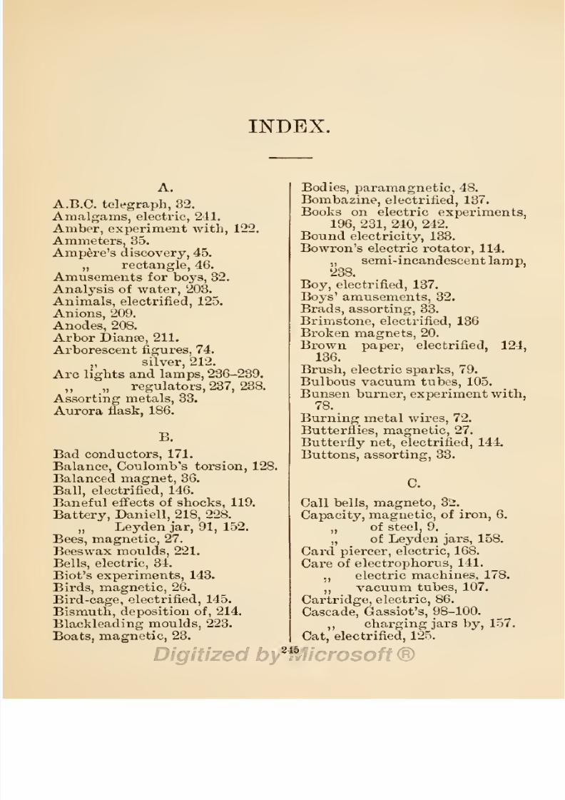
8/20/2019 electrical experiment.pdf
http://slidepdf.com/reader/full/electrical-experimentpdf 263/325
INDEX.
A.
A.B.C.
telegraph,
32.
Amalgams,
electric,
241.
Amber,
experiment
with,
122.
Ammeters,
35.
Ampere's
discovery,
45.
„ rectangle,
46.
Amusements
for
boys,
32.
Analysis
of
water,
203.
Animals,
electrified,
125.
Anions,
209.
Anodes,
208.
Arbor
Dianse,
211.
Arborescent
figures,
74.
„ silver,
212.
Arc
lights
and
lamps,
236-239.
„
„
regulators,
237,
238.
Assorting
metals,
33.
Aurora
flask,
186.
B.
Bad
conductors,
171.
Balance,
Coulomb's
torsion,
128.
Balanced
magnet,
36.
Ball,
electrified,
146.
Baneful
effects of
shocks,
119.
Battery,
Daniell,
218,
228.
„
Leyden
jar,
91,
152,
Bees,
magnetic,
27.
Beeswax
moulds,
221.
Bells,
electric,
34.
Biot's
experiments,
143.
Birds,
magnetic,
26.
Bird-cage,
electrified,
145.
Bismuth, deposition
of,
214.
Blackleading
moulds,
223.
Boats,
magnetic,
23.
Bodies,
paramagnetic,
48.
Bombazine,
electrified,
137.
Books
on
electric
experiments,
196, 231,
240,
242.
Bound
electricity,
133.
Bowron's electric
rotator,
114.
„
semi-incandescent
lamp,
238.
Boy,
electrified,
137.
Boys' amusements,
32.
Brads,
assorting,
33.
Brimstone,
electrified,
136
Broken
magnets,
20.
Brown
paper,
electrified,
124,
136.
Brush,
electric
sparks,
79.
Bulbous
vacuum
tubes,
105.
Bunsen
burner,
experiment
with,
78.
Burning
metal
wires,
72.
Butterflies,
magnetic,
27.
Butterfly
net,
electrified,
144.
Buttons,
assorting,
33.
Call
bells, magneto,
32.
Capacity,
magnetic,
of
iron,
6.
,,
of
steel,
9.
„
of
Leyden jars,
158.
Card
piercer,
electric,
168.
Care
of
electrophorus,
141.
.,
electric
machines,
178.
,,
vacuum
tubes,
107.
Cartridge,
electric,
86.
Cascade,
Gassiot's,
98-100.
,,
charging
jars
by,
157.
Cat,
electrified,
125.
245

8/20/2019 electrical experiment.pdf
http://slidepdf.com/reader/full/electrical-experimentpdf 264/325

8/20/2019 electrical experiment.pdf
http://slidepdf.com/reader/full/electrical-experimentpdf 265/325
INDEX.
247
Dr.
Knight's magnets,
12.
Dr.
Wright's
cohesion
experi-
ment,
75.
Dr. Gilbert's
discovery,
123.
Drying
oil
by
electricity,
77.
Duhamel's
magnets,
13.
Da
Fay's
theories,
132.
Dust
figures,
Lichtenberg's,
82.
Dynamo,
magnetizing
by,
17.
E.
Effects
of
electrical
discharges
—
physiological,
117
;
mechani-
cal,
188,
193;
heating,
186;
luminous,
186.
Effects
of
magnet
on
electric
striae,
97.
Effects
of
various
electrodes
on
electric
sparks,
98.
Egg,
electric,
96.
Electric
bells,
34
;
endless
chain,
45
;
hammer,
59
;
stencil,
73
;
stars,
74
;
dust
figures,
82
;
gas
lighter,
83
;
pistol,
84
;
fuse,
85
; cartridge,
86
;
glass
breaker,
92
;
egg,
94
;
lamps,
110,
235
;
rotators, 112,
113
;
fan,
115
;
shocks,
119
;
mortar,
167
; kiss,
194
;
amalgam,
cement, varnish,
241
; light,
235.
Electrical
value
of
thermopiles,
233,
234.
Electrical
condition
of
glass,
ebonite,
shellac,
resin,
seal-
ing-wax,
124.
Electrical
chimes,
166;
machines,
175.
Electricity,
in
transitu,
115
;
static,
121
;
and
magnetism,
122.
Electrified
water
and
coin,
118
;
brown
paper,
124,
135
;
cat,
125
;
horse
and
animals,
125
;
boy,
bombazine,
brimstone,
catskin,
chips,
chalk, coffee,
cork,
copper,
cotton,
ebonite,
flannel,
far, glass,
glove, gut-
tapercha, gun-cotton,
gun-
paper,
hair,
horsehair,
hand-
kerchief,
i
idia-rubber, ivory,
resin,
ribbon,
rock
crystal,
sealing-wax,
silk, sulphur,
silk,
wood
wool,
134-136
;
birdcage,
metal
cup,
145;
cone,
150;
ball,
cylinder,
147
;
head
of
hair,
193.
Electro-magnets,
51
;
use
of,
67.
„
magnetic
induction,
43.
„
attraction
and
repulsion,
45.
„
portation,
55.
„
solenoid,
58.
,,
motors,
115.
Electrodes,
98.
Electrometer, Thompson's,
130
;
Lane's
Leyden
jar,
Harris's
unit
jar,
131.
Electrophorus,
137
;
price,
use
of,
139
;
experiments
with,
and
care
of,
141.
Electroscope,
pith-ball,
130,
131;
gold-leaf,
127
; Henley's,
130
;
Lever's,
(Dotterel's,
Thomp-
son's,
130.
Electro-depositions
of
metals,
210,
227;
battery
for,
228
solutions
for,
229.
Electrolysis,
197
;
current
for,
198
;
of
water,
197
;
metallic
salts,
207;
coloured
fluids,
203.
Electrolyte,
197.
Electros,
backing
and
mounting,
227.
Electrotypes,
single
cell,
216
;
experiments,
219
;
of
medals,
coins,
etc.,
220
;
fishes,
ferns,
and
leaves,
224
;
of
stamped
and
engraved
surfaces,
226
;
printing
type,
226.
E.M.F.
of
induced
currents,
109.
„
of
sparks
from
coil,
109,
117.
Engraved
surfaces,
copying,
226.

8/20/2019 electrical experiment.pdf
http://slidepdf.com/reader/full/electrical-experimentpdf 266/325
243
INDEX.
Experiments
with
lighted
taper,
78
;
Bunsen
burner,
smoked
points,
79
;
horse-shoe
mag-
net,
53
;
electrified
ball,
147
;
spherical
condenser,
149.
Exploding
ether,
powder,
etc.,
79.
Fan, electric,
115.
Faraday's
discoveries,
48.
„
butterfly
net,
144.
Ferns,
electrotypes
of,
224.
Figures,
arborescent,
74.
„
electric
dust,
82.
Filings,
iron,
17,
31
;
steel,
52.
„
deflagrating,
72.
Finding
poles
of
magnet,
54.
Finishing
electrotypes,
224.
Fire
from
water,
75.
Firing
gun-cotton,
79,
87
; ether,
powder,
lycopodium,
79.
Fish, magnetized,
25.
Fizeau's
condenser,
175.
Flaming sparks,
79.
Flannel,
electrified,
133,
134.
Flask,
aurora,
186.
Floating needles,
23.
Foil,
metal,
firing,
73.
Forms
of
sparks
from
coil,
78.
Franklin's
fulminating
pane,
174.
,,
theories,
132.
Friction,
electrical
effects
of,
134.
Fulminating
mixture,
168.
„ pane,
173.
Fur,
electrified,
124.
Fuses, electric,
85-87.
Fusible
metal,
222.
G.
Galvanometers,
35.
Gases, experiment
with,
97.
Gas-lighter,
electric,
83,
187.
Gassiot's
cascade,
98.
„
experiments
with,
100.
tubes,
106.
Geese,
magnetized,
25.
Geissler
tubes,
102.
Gilding coins,
medals,
etc.,
230.
Glass
breaker,
92
;
uranium,
99.
„
electrified,
124
;
rod,
132.
„
piercing,
168,
169.
Glove,
electrified,
137.
Gold,
electro-deposition
of,
215.
„
-leaf
electroscope,
127.
Gore's
experiments,
216.
Guide
to
books,
196,
242.
Gun,
magnetic,
26.
Gun-cotton,
79,
87,
134.
Gutta-percha,
electrified,
134.
„ „
moulding
in,
221.
H.
Hair,
head
of,
electrified,
193.
Hammer,
electric,
59.
Hand rotator for
tubes,
111.
Handkerchief,
electrified,
137.
Harris'
unit
Leyden
jar,
131,
160.
Heating
effects of
electricity,
186.
Helical
contact-breaker,
63.
Helix,
61-2.
Hemispheres,
magic,
65.
„ charged,
143.
Henley's
discharger
for
coils,
71.
„
universal
discharger,
164-5.
„ pith-ball
electroscope,
130.
„
quadrant,
159.
Henry's,
Prof., experiments,
119.
High
insulation
Leyden
jars,
153.
Hollow
sphere,
electrified,
142.
Hook, magnetized,
26.
Horsehair,
electrified,
136.
Horse-shoe
magnet,
11.
„
electro-magnet,
53.
Horse, electrified,
125.
Hot
air,
conductivity
of,
77.
Igniting
phosphorus,
80.
Impulsion
sparks
and
effects,
80.
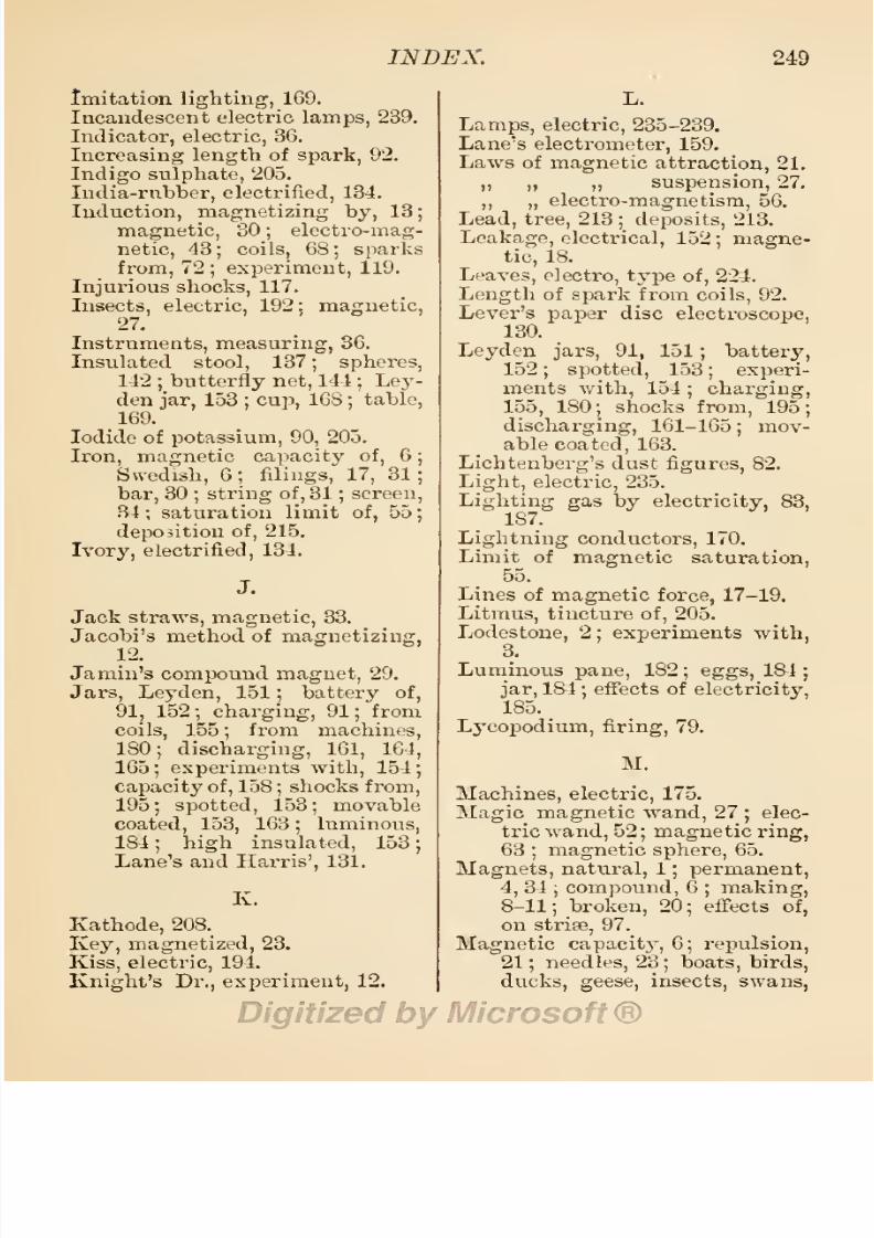
8/20/2019 electrical experiment.pdf
http://slidepdf.com/reader/full/electrical-experimentpdf 267/325

8/20/2019 electrical experiment.pdf
http://slidepdf.com/reader/full/electrical-experimentpdf 268/325
250
INDEX.
etc.,
27
;
suspension,
27
;
pendulum,
28
;
induction,
30
;
screens,
33
;
shell,
41.
Magnetism
and
electricity, 5,
40.
Magnetized
key,
23
;
iron,
30.
Magnetizing
steel,
3,
10, 12,
17.
Magneto
call
bells,
32.
Mahomet's
coffin,
28.
Making magnets,
8-11.
Mariner's
compass,
37.
Matthiessen's
table
of
thermo-
electric
elements,
233.
Mayer's
magnetic
floating
needles,
23.
Measuring
charge
of
jars,
159.
„
instruments,
36.
Mechanical
effects
of
discharges,
188.
Medals,
copying,
220,
222;
gild-
ing,
230.
Mercury, deposition of,
214.
Metal
cup,
electrified,
145.
Metallic
salts, electrolysis
of,
207.
Microfarad
condenser,
175.
Miscellaneous
magnetic
experi-
ments,
32.
Models, electric,
172.
Modifying
electric
sparks,
78.
Mortar,
electric,
167.
Moss,
silver,
212.
Moulding,
in
gutta-percha,
221
;
beeswax,
221
;
plaster,
221
;
clichee,
fusible
metal,
etc.,
222.
Moulds,
blackleading,
223.
Mounting
electros,
227.
Movable
coated
jars,
153,
163.
Multiplier,
electric,
47.
N.
Nails,
assorting,
33.
Natural
magnets,
1.
Needle,
floating,
23
; dipping,
39.
Negative
dust
figure,
82
;
elec-
tricity,
133
;
substances,
134.
Nickel,
magnetic, 6;
deposit
of,
215
;
solution
of,
231.
Nickelling,
231.
Nitrate of
potash,
205.
Nobili's
rings,
214.
O.
Obelisk,
model
of,
172.
Oersted's
discovery,
45.
Oils,
effects
of
sparks
on,
77
Ornamental
tubes,
106
;
silver
plate,
210.
Orrery,
electric,
189.
P.
Pane,
luminous,
182.
Paper,
brown
electrified,
124,
136.
Papyroxyline,
138.
Paramagnetic
bodies,
48.
Pendulum, magnetic,
28.
Permanent
magnet,
4-S
;
use
of.
34.
Phosphorus,
igniting,
80.
Physiological
effects
of
electri-
city,
117,
193.
Piercing
glass
and
cards,
169.
Pins,
assorting,
33.
Pith-ball
electroscopes,
125-130.
„
experiments
with,
131.
Plane,
proof,
141.
Platinum, deposition
of,
215.
Plaster
of
Paris, moulding,
221.
Plastic
materials,
moulding,
222.
Plating
solutions,
229
;
powders,
sham,
214.
Points, smoked,
of
discharger,
78.
Polarity
of
solenoids,
61
;
wire
helix,
62.
Poles
of
magnet, finding,
54.
Portative
force
of
magnet,
29
;
of
electro
magnet,
55.
Positive
dust
figure,
82;
elec-
tricity,
133.
Potassium
iodide,
90,
205
;
sul-
phate,
204
;
nitrate,
205.

8/20/2019 electrical experiment.pdf
http://slidepdf.com/reader/full/electrical-experimentpdf 269/325
INDEX.
251
Powder,
exploding,
79,
86.
Power
required
to
magnetize
steel,
14.
Price
of
magnets,
6
;
electro-
meters,
160
5
Wimshurst
machines,
177.
Printing-type
copying,
226.
Proof
plane,
111.
Prof. Crookes'
experiments,
116.
„
Henry's
experiments,
119.
Q.
Quadrant, Henley's,
159.
Quality
of
steel
for
magnet,
8.
R.
Reciprocal
action
of
magnetism
and
electricity,
32.
Rectangle,
Ampere's,
46.
Relation
of
magnetism
to
elec-
tricity,
40,
122.
Repulsion,
magnetic,
45.
Resin,
electrified,
124,
134.
Resinous
electricity,
132.
Ribbon,
electrified,
136.
Ring
rotators,
112.
Rings,
Nobili's,
214.
Rock
crystal,
electrified,
13 J.
Rotating
vacuum
tubes,
110.
Rotators
for
vacuum
tubes,
111,
112,
114.
S.
Saturation
limit of
iron,
55.
Screens,
magnetic,
34.
Sealing-wax,
electrified,
123,
131,
134.
See-saw,
electric,
190.
Semi-incandescent
lamp,
238.
Sham
plating
powder,
214.
Shellac,
electrified,
124;
rod
and
pith ball,
133.
Ship, electric,
172.
Shocks
from
coils, 117-119;
from
electrical
machines,
194;
from
Leyden
jars,
195.
Shocking
machines,
34.
Silk,
electrified,
124
;
glove,
137
;
handkerchief,
134,
136.
Silver,
deposition
of,
211
;
orna-
mentation
of,
210
;
moss
and
tree,
212;
arboi'escent,
212;
plating
solution,
229.
Simple
electro-magnet,
51
;
de-
position
of
metals,
210
;
arc
lamp,
237.
Single
cell
deposition,
215,
216,
227.
Single
touch,
magnetizing
by,
10.
Smoked
points
of
discharger,
78.
Solutions
for
electro
deposition,
229.
Spangled
tube,
181.
Spark
coils,
68
;
discharge
from,
71
;
sparks
from,
72.
Sparks,
from
water,
76
;
from
oil,
77
;
modifying
forms
of,
78
;
brush,
flashing,
and
de-
tonating,
79
;
impulsion,
80
;
length
of,
92
;
colour
of,
96-
98.
Sprague's
observations,
5.
Spherical
condenser,
149.
Spotted
Leyden
jar,
153.
Stamped
surfaces, copying,
226.
Stars,
electric,
74,
111.
Static
electricity,
121
;
magne-
tizer,
173.
Steel, testing,
4
;
quality
of,
8
;
capacity
of,
6-9
;
magne-
tizing,
3.
8-10,
12-17
;
filings,
52.
Stencil,
electric,
73.
Stool,
insulated,
137.
Striss,
electric, 94,
97, 101,
116.
Strengthening
weak
magnets,
8.
String
of
magnetized
irons,
30.
Sulphur,
electrified,
134.
Sulphate
of
potash,
204
;
indigo,
205
;
copper,
208.
Sulphuric
ether,
firing,
79.
Superior
conductivity
of
hot
air,
17.
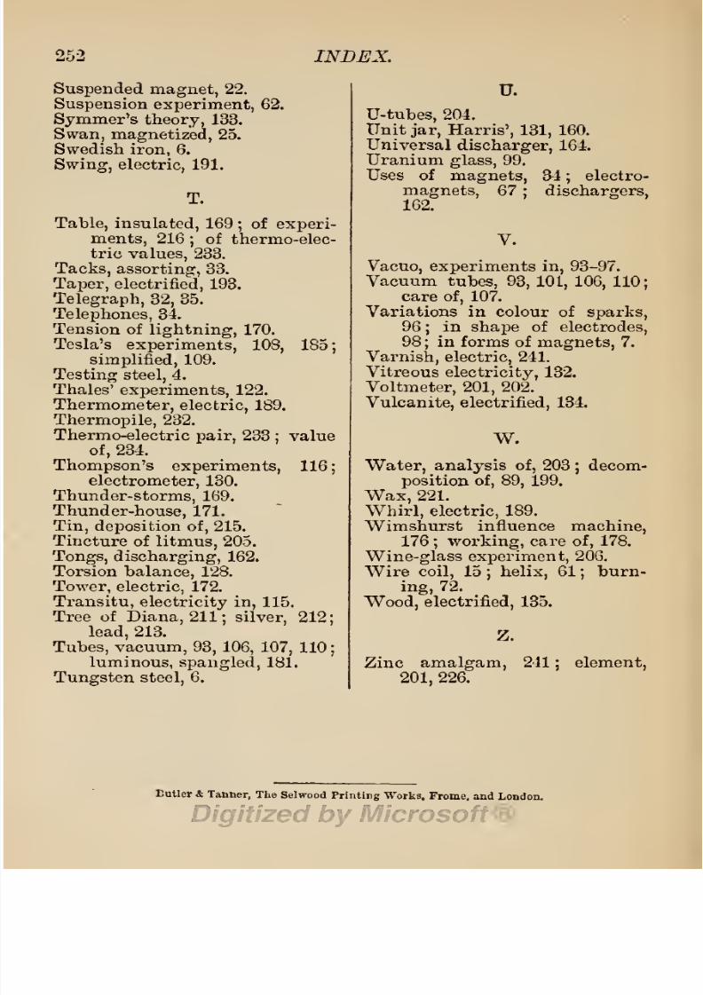
8/20/2019 electrical experiment.pdf
http://slidepdf.com/reader/full/electrical-experimentpdf 270/325
252
INDEX.
Suspended
magnet,
22.
Suspension
experiment,
62.
Symmer's
theory,
133.
Swan,
magnetized,
25.
Swedish
iron,
6.
Swing, electric,
191.
T.
Table,
insulated,
169
;
of
experi-
ments,
216
;
of
thermo-elec-
tric
values,
233.
Tacks,
assorting,
33.
Taper,
electrified,
193.
Telegraph, 32,
35.
Telephones,
34.
Tension of
lightning,
170.
Tesla's
experiments,
108,
185;
simplified,
109.
Testing steel,
4.
Thales'
experiments,
122.
Thermometer,
electric,
189.
Thermopile,
232.
Thermo-electric
pair,
233
;
value
of,
234.
Thompson's
experiments,
116
;
electrometer,
130.
Thunder-storms,
169.
Thunder-house,
171.
Tin, deposition
of,
215.
Tincture of
litmus,
205.
Tongs,
discharging,
162.
Torsion
balance,
128.
Tower,
electric.
172.
Transitu,
electricity
in,
115.
Tree of
Diana,
211;
silver,
212;
lead,
213.
Tubes,
vacuum,
93,
106,
107,
110;
luminous,
spangled,
181.
Tungsten
steel,
6.
U.
U-tubes,
204.
Unit
jar,
Harris', 131,
160.
Universal
discharger,
164.
Uranium
glass,
99.
Uses
of
magnets,
34
;
electro-
magnets,
67
; dischargers,
162.
V.
Vacuo, experiments in,
93-97.
Vacuum
tubes,
93,
101,
106,
110;
care
of,
107.
Variations
in
colour of
sparks,
96
;
in
shape
of
electrodes,
98
;
in
forms of
magnets,
7.
Varnish, electric,
241.
Vitreous
electricity,
132.
Voltmeter, 201,
202.
Vulcanite,
electrified,
134.
W.
Water, analysis
of,
203
;
decom-
position of, 89,
199.
Wax,
221.
Whirl, electric,
189.
Wimshurst
influence
machine,
176
;
working,
care
of,
178.
Wine-glass experiment,
206.
Wire
coil,
15
;
helix,
61
;
burn-
ing,
72.
Wood,
electrified,
135.
Z.
Zinc
amalgam,
241
;
element,
201,
226.
Eutler
&
Tanner,
The
Selwood
Printing
Works,
Frome,
and
London.

8/20/2019 electrical experiment.pdf
http://slidepdf.com/reader/full/electrical-experimentpdf 271/325
S.
BOTTONE,
Electrician,
WALLINGTON,
SURREY,
Manufactures
and
supplies
all
the
apparatus
needed for
the
experiments
described
in this
book,
as
well
as
parts
thereof. The articles
stocked are
:
—
Accumulators, from
5/-
each;
Ammeters,
5/-;
Batteries,
2/6;
Induction
Coils,
7,6;
Resistance
Coils,
2/6;
Dynamos,
15/-;
Electromotors,
10/- ;
Cast-
ings
for
either,
4/- ;
Electrical Machines—
Cylinder,
Plate,
Wimshurst,
and
other
types
—
from
£1
10s.
Electrophori,
from
5'- ;
Galvanometers,
2/6 ;
Lamps,
both
Incandescence
and
Arc,
from
5/-
to
£5
;
Leyden
Jars,
Conden-
sers,
Wheatstone
Bridges,
from
5/-
; Volfmeters,
5/-
; etc.,
etc.
FULL
LISTS,
lid.
POST
FREE.
BOOKS
by
S.
t
BOTTONE.
PUBLISHED
by
OJHITTAKEK
&
GO.
HOW
TO MANAGE
A
DYNAMO. A Practical Handbook
for
Workmen and others.
Second
Edition,
revised.
Illustrated.
Pott
8vo,
for
the
pocket,
cloth,
Is.
ELECTRO-MOTORS,
HOW
MADE
AND
HOW
USED.
A
Handbook
for Amateurs and Practical
Men. With
88
Illus-
trations.
Third
Edition,
revised
and
enlarged,
3s.
Mr. Bottone
has the
faculty
of
writing
so as to be
understood
by
amateurs.
—
Industries.
ELECTRICAL
INSTRUMENT-MAKING
for
AMATEURS.
A Practical
Handbook.
With
71
Illustrations. Sixth
Edition,
revised
and
enlarged,
3s.
To
those
about
to
study
electricity
and
its
application,
this
book will
form
a
very
useful
companion.
—
Mechanical World.
ELECTRIC
BELLS,
AND
ALL
ABOUT THEM.
A Prac-
tical
Book for
Practical Men. With
more
than
100
Illustrations.
Fifth
Edition,
revised,
3s.
Any
one desirous
of
undertaking
the
practical work
of
electric
bell-fitting
will
find
everything,
or
nearly
everything,
he
wants to
know.
—
Electrician.
No bell-fitter
should
be
without
it.
—
Building
News.
A
GUIDE
TO
ELECTRIC
LIGHTING. For
Householders and
Amateurs.
With
many
Illustrations.
Pictorial
cover,
Is.
Accurate,
lucid,
and
suitable for
the
purpose.
—
Electrician,
The
chapter
on
accumulators
is
perhaps
one of
tho
best
in
the
book.
—
Electrical
Review.
ELECTRICITY
AND
MAGNETISM.
An
easy
Introduction to
the
Science.
With
about
100
Illustrations.
2s.
6d.
S.
R.
BONNEY,
EIectro=
Plater,
etc.,
6,
Manor
Park
Parade
High
Boad,
Lee,
S.E.
Instruments and
Apparatus
for
Electrical
Experiments
made
and
repaired.
Materials
for
Electric
and
Mag-
netic
Belts
supplied.
l

8/20/2019 electrical experiment.pdf
http://slidepdf.com/reader/full/electrical-experimentpdf 272/325
Wbtttaker's
library
OF
Evts,
Sciences,
/Ifoanufactures,
ant)
Snfcustrfes.
Illustrated.
In
Square
Crown
8vo,
Cloth.
Messrs.
Whittakefs
valuable
series
of practical
manuals. —
Electrical
Kevieio.
By
W.
Pebren
Maycock,
M.I.E.E.
FIRST
BOOK
OF ELECTRICITY
AND
MAGNETISM.
Second
Edition,
Revised
and
Enlarged,
with 107 Illustrations.
2s. 6d.
Students
vrho
purchase
a
copy,
and
carefully
study it,
will obtain an
excellent
groundwork
of the
science.
—
Electrical Review.
As a first
book
for
such students
as
have
to
pass
examinations,
it
is
admirable.
—
Electrical
Engineer.
By
the
Same
Author.
ELECTRIC LIGHTING
AND
POWER
DISTRIBUTION,
An
Elementary
Manual of.
For
Students
preparing
for the
Preliminary
and
ordi-
nary
Grade
Examination of the
City
and Guilds
of
London
Institute
and
general
readers.
Third
Edition,
revised
and
enlarged,
in
2
volumes. Vol.
I.,
430
pp.,
with
231
Illustrations. Crown
8vo. 6s.
*'
The
work
will
no
doubt become a standard text-book for
schools
and
classes
on
this
subject ;
as
such it
has
few
equals. —
Electrical
Review.
FITTING,
THE
PRINCIPLES
OF.
For
Engineer
Students.
By
J.
Hobneb,
M.I.M.E.
Illustrated
with
about
250
Engravings,
and
containing
an
Appendix
of
Useful
Shop
Notes
and
Memoranda.
5s.
A
practical
manual
for
practical people.
—
E«glis7i,
Mechanic.
*
'
Calculated to aid
and
encourage
the
most
useful
set
of hau
dicraftsmen we have
amongst
us.
—
Daily
Chronicle.
THE
PRINCIPLES
OF
PATTERN
MAKING.
Written
specially
for
Apprentices,
and for
Students
in
Technical
Schools.
By
J.
Hohnek,
M.I.M.E. Illustrated with 101
Engravings,
and
containing
a
Glossary
of
the
Common Terms
employed
in
Pattern
Making
and
Moulding.
3s.
6d.
The
book
is
well
illustrated,
and
for
its
size will
be
found one
of
the best of
its
kind.
—
Industries.
This is
one of
those
works which have
a
more
than
ordinary
value.
—
Steamship.
PRACTICAL
IRONFOUNDING.
By
J.
Horner,
M.I.M.E.,
a
Fore-
man
Pattern
Maker. Illustrated with
over
100
Engravings.
Second
Edi-
tion.
4s.
Every
pupil
and
apprentice
would
find
it,
we
think,
an
assistance
to
obtaining
a
thorough knowledge
of his
work.
The
book,
however,
is
not
intended
merely
for
the
student,
but contains much useful information
for
practical
men.
—
Industries.
METAL
TURNING.
By
J.
Horner,
M.I.M.E.
With
81
Illustra-
tions. 4s.
Contents
:
The
Lathe
—
Tools and Tool
Angles
—
Chucks
—
Chucking
—
General
Remarks
on
Turning—
Hand
Turning—
Slide Rest
Turning—
Boring—
Screw
Cut-
ting,
etc.
A
handy
little work.
—
Ironmonger.
An
exceedingly
useful
publication
to
have at hand. —
Machinery.
By
G.
E.
Bonnet.
ELECTRICAL
EXPERIMENTS.
With 144
Illustrations.
2s.
6d.
This is an
excellent book
for
boys. —
Electrical
Review.
2

8/20/2019 electrical experiment.pdf
http://slidepdf.com/reader/full/electrical-experimentpdf 273/325
By
G. E.
Bonnet.
INDUCTION
COILS.
A
Practical
Manual
for
Amateur
Coil-makers.
With
a
New
Chapter
on Coils
for
Radiography.
With 101
Illustrations. 3s.
In
Mr.
Bonney's
useful
book
every
part
of the
coil
is
described
minutely
in de-
tail,
and
the methods
and
materials
required
in
insulating
and
winding
the wire
are
fully
considered.
—
Electrical Review.
By
G. E. Bonney.
THE
ELECTRO-PLATER'S
HANDBOOK.
A
Practical
Manual
for Amateurs and
Young
Students
in
Electro-Metallurgy.
With Pull
Index
and
61
Illustrations.
Second
Edition,
Revised
and
Enlarged,
with an
Ap-
pendix
on
ELECTROTYPING.
3s.
An
amateur
could
not
wish
for a
better
exposition
of the elements of the
subject.
—
Electrical
Review.
By
H.
Obfoed.
LENS
WORK
FOR
AMATEURS.
With
numerous
Illustrations.
Small
crown
8vo.
3s.
The
author
is
both
a sound
practical
opticiau
and
is
able to
convey
his know-
ledge
to others
in
a clear
manner. —
British
Journal
of
Photography.
MODERN OPTICAL INSTRUMENTS.
By
the same
Author. 2s. M.
By
J.
Traill
Taylor,
Editor of The
British
Journal
of Photography.
THE
OPTICS OF
PHOTOGRAPHY
AND
PHOTOGRAPHIC
.LENSES.
With 63 Illustrations.
3s.
6el.
Personally
we
look
upon
this book as a
most valuable
labour-saving
invention,
for
no
questions
are so
frequent,
or take so
long
to
answer,
as
those
about lenses.
^-Practical
Photographer.
By
Joseph
Poole,
A.I.E.E.
(Wh.
Sc.
1875),
Chief
Electrician to
the
New
Telephone
Company,
Manchester.
THE PRACTICAL TELEPHONE HANDBOOK.
With 228 Illus-
trations.
Second Edition.
Revised
and
considerably
Enlarged.
6s.
This
essentially practical
book
is
published
at
an
opportune
moment. It
con-
tains
readable
accounts
of
all
the best-known and most
widely
used
instruments,
together
with
a
considerable
amount
of
information
not
hitherto
published
in
book
form.
—
Electrician.
Will
be
found
most
useful
and
interesting
to
persons
who
use the
telephone,
as
Mr. Poole's
exposition
of
telephonic
apparatus
is
both
clear
and
comprehensive.
—
Saturday
Review.
By
Sydney
F.
Walker,
M.I.E.E.,
A.M.Inst.C.E.
ELECTRICITY
IN
OUR
HOMES
AND
WORKSHOPS.
A
Prac-
tical
Treatise
on
Auxiliary
Electrical
Apparatus.
Third
Ediiion.
Revised
and
Enlarged.
With
113
Illustrations.
6s.
It
would
be
difficult
to
find a
more
painstaking
writer
when
he is
describing
the
conditions
of
practical
success
in a
field
which
he
has himself
thoroughly
ex-
plored.
—
Electrician.
Mr.
Walker's
book
is
evidently
the work of a
practical
man
who
has had
much
experience.
.
. .
The
practical
hints
are
likely
to
be
of solid
value.''
—
Saturday
Revieiv.
By
D.
Denning.
THE
ART
AND
CRAFT
OF
CABINET
MAKING.
A
Practical
Handbook
to
the
Construction
of
Cabinet
Furniture,
the
Use
of
Tools,
Forma-
tion of
Joints,
Hints
on
Designing
and
Setting
Out
Work,
Veneering,
etc.
With 219
Illustrations. 5s.
We
heartily
commend
it.
—
Cabinet
Maker.
Well
planned,
and
written
in
a
pleasing
and
simple style.
—
Nature.
A
carefully-considered
and well-writtea
book.
—
Work.
By
F.
C.
Allsop,
Author of
The
Telephones
and
their
Construction.
PRACTICAL
ELECTRIC-LIGHT
FITTING.
A
Treatise on
the
Laying
Down
of
Private
Installations,
including
the latest
edition
of
the
Wiring
3

8/20/2019 electrical experiment.pdf
http://slidepdf.com/reader/full/electrical-experimentpdf 274/325
and
Fitting-up
of
Buildings
deriving
current from
Central
Station
Mains,
Phoenix
Fire
Office Rules.
With 221
Illustrations. Second
Edition,
revised,
5s.
A book we
have
every
confidence
in
recommending.
—
Daily
Chronicle.
A
highly practical
and
useful
hook.
—
Lighting.
The
book
is
certainly
very
complete.
—
Electrical Review.
By
J.
Hopkinson,
D.Sc,
F.R.S.
DYNAMO
MACHINERY,
ORIGINAL
PAPERS ON.
With
98
Illustrations.
5s.
Must
prove
of
great
value
to
the student
and
young
engineer. —
Electrical
Review.
A
most valuable
work.
—
English
Mechanic.
By
S.
R.
Bottone.
THE DYNAMO :
How
Made
and
How
Used.
Ninth
Edition,
with additional matter and Illustrations.
2s.
6d.
By
Sir
David
Salomons,
Bart.,
M.A.,
Vice-President
of
the
Institution of
Electrical
Engineers,
etc.
ELECTRIC-LIGHT
INSTALLATIONS,
AND
THE
MANAGEMENT
OF
ACCUMDLATOES.
A Practical
Handbook. Sixth
Edition,
Revised and
Enlarged,
with
numerous
Illustrations. 6s.
We
advise
every
man
who
has to do with installation work to
study
this
work.
—
Electrical
Engineer.
To
say
that
this
book is
the
best
of
its kind
would
be a
poor
compliment,
as it is
practically
the
only
work
on
Accumulators
that has been
written.
—
Electrical
Review.
By
J. Gray.
B.Sc.
ELECTRICAL INFLUENCE
MACHINES
:
containing
a
Full
Ac-
count
of their Historical
Development,
their Modern
Forms,
and
their
Prac-
tical
Construction. 4s.
6d.
This
excellent
book.
—
Electrical
Review.
By
Edwin
J.
Houston, A.M.,
Professor
of Natural
Philosophy
and
Physical
Geography
in
the Central
High
School
of
Philadelphia,
Professor
of
Physics
in
the
Franklin
Institute
of
Pennsylvania,
etc.
ADVANCED
PRIMERS OF
ELECTRICITY.
Vol.
I.—
ELECTRICITY
AND
MAGNETISM.
Ss.
Gd.
Vol.11.—
ELECTRICAL TRANSMISSION OF
INTELLIGENCE.
5s.
Vol.
III.—
ELECTRICAL
MEASUREMENTS.
5s.
We recommend
the book
strongly
to
all
electricians.
—
Electrical
Plant.
THE ALTERNATING
CURRENT CIRCUIT :
an
Introductory
and
Non-Mathematical
Book
for
Young
Engineers
and
Students.
By
W.
Pebben
Matcock,
M.I.E.E.
With 46
Illustrations.
Small
crown 8vo. Cloth. 2s.
6d.
THE
METRIC
SYSTEM
OF
WEIGHTS AND
MEASURES
COM-
PARED
WITH
THE
IMPERIAL
SYSTEM.
By
W.
H.
Wagstaff,
M.A.,
Professor
of
Geometry
at
Gresham
College.
Crown 8vo.
Cloth. Is. 6o\
ENGINEER
DRAUGHTSMEN'S
WORK.
Hints
for
Beginners.
By
a
Practical
Draughtsman.
With 80
Illustrations.
Small
crown
8vo.
Cloth.
Is. 6<Z.
Will
be found
of
practical
value
to
the
beginner
in
the
Drawing
Office.
—
Engineer.
PRACTICAL
ELECTRICAL
MEASUREMENTS.
An
Introductory
Manual
in Practical
Physics
for Students
and
Engineers.
By
E.
H.
Crappeb,
Lecturer
in
Electrical
Engineering
at the
Sheffield
Technical
School.
With
£6
Illustrations.
Crown
8vo.
2s.
6d.
Contents.
—
Magnetic
Fields
and
their Measurements
—
Action of
a
Magnetic
Field
on
a
Magnet
or Needle
—
Action
of
a
Magnet
upon
another
Magnet
—
Currents
of
Electricity
and
their
Effects—
Exercises with
Tangent
Galvanometer
—
Mirror Gal-
vanometer and
Simple
Measurements—
Measurement of
Resistance
—
The
Theory
of
the Wheatstone's
—
Shunts,
Measurements
of
E.M.F.'s,
Heating ESects,
and
Ther-
mal
Currents
—
Electro-Magnetism
—
Induction
of
Currents.
LONDON:
WHITTAKER
&.
CO.,
White Hart
Street,
Paternoster
Square,
E.C.

8/20/2019 electrical experiment.pdf
http://slidepdf.com/reader/full/electrical-experimentpdf 275/325

8/20/2019 electrical experiment.pdf
http://slidepdf.com/reader/full/electrical-experimentpdf 276/325
2
Whittaker's
Technological
and
Scientific
List.
1HE
SPECIALISTS*
SERIES
{Continued).
By
G.
A.
T.
MiDDLETON,
A.R.I.B.A.,
M.S.
A.,
Author
of
'Strains
in
Structures,' &c,
&c
SURVEYING
AND
SURVEYING
INSTRU-
MENTS.
With
41
Illustrations.
4s.
Gd.
Contents
:
—
Surveys
with
Chain
only
—
Obstructions
in
Chain-Line
and
Right-Angle
Instruments
—
The Uses
of the
Level
—
Various
Forms of
Level
and
their
Adjustments
—
The Uses
of
Angle-measuring
Instruments
—
The
Theodolite
and other
Angle-measuring
Instruments
—
Instruments
for Ascer-
taining
Distances.
'
This
is
a
very
neat
little
text-book,
and
very
suitable for students
preparing
to
pass
the
Institute
examinations.'—
Journ. 0/ Royal
Inst, of
British
Architects.
By
J.
O.
Arnold,
Professor of
Metallurgy,
Sheffield Technical
School.
STEEL
WORKS
ANALYSIS. With
22 Illustrations
and
Diagrams.
Crown 8vo.
\os. 6d.
Contents
:
—
The Steel
Works
—
Laboratory
and
Appliances
—
Section
I.
Analysis
of
Steel
and
Wrought
Iron
;
II.
Analysis
of Iron
Ore
;
III. Refrac-
tory
Materials
;
IV.
Fuel
;
V.
Sundries.
'This
book
is
of
an
essentially
practical
character.'
—
Engineer.
'Everything
that
a steel-works'
analyst
may
fairly
be called
upon
to examine
finds
a
place
in
this
volume
Prof.
Arnold has
rendered
steel-works'
analysis
a
decided
service
by
the
publication
of his
work.'
Prof.
John
Parry
in
Nature.
k
We
can
heartily
recommend
this book.'
—
Electrician.
By
C
C.
Hawkins,
M.A.,
A.I.E.E.,
and F.
Wallis,
A.I.E.E.
THE
DYNAMO,
ITS
THEORY,
DESIGN
AND
MANUFACTURE.
With
190
Illustrations,
mostly
from
original
Drawings.
Second
Edition,
Revised,
ior. 6d.
Contents
:
—
The
Magnetic
Field
—
The
Magnetic
Circuit
—
The
Production
of
an E.
M.
F.
—
The
Magnetic
Pull
—
Self
Induction
—
Classification
of
Dynamos
—
Bi-
and
Multi-polar
Alternators
—
Unipolar
Alternators
—
Open-
Coil
Armatures
—
Closed-Coil
Armatures
—
The
Magnetisation
of
Iron
—
Armatures
—
Field
Magnets—
The
Ampere
—
Turns
of
the Field
—
Series,
Shunt,
and
Compound
Winding
—
Sparking
and
Angle
of
Lead
—
Heating
of
Dynamos
—
Typical
Dynamos
—
Dynamo
Designing
—
The
Working
and
Management
of
Dynamos.
'
A
work
Of
no
mean
ability.
One
valuable
feature
throughout
the
book
is
the
excellence
and
number
of the
illustrations.'
—
Electrical
Engineer.
'The
work
is
well-arranged
. . .
the
explanations
are clear
and
the
formulae
simple.
. .
. The classification
of
dynamos
is
very
good
and
rational.'
—
Electrical
Review.
'We
welcome
this
book
as
a
thoroughly
trustworthy
and
useful
work.'
Elect}
iciam.
'An
admirable
exposition
01
the
theory
and
practice
of
the
modern
dynamo.
A
tkenautH.

8/20/2019 electrical experiment.pdf
http://slidepdf.com/reader/full/electrical-experimentpdf 277/325
W/iittaker's
Technological
and
Scientific
List.
THE
SPECIALISTS'
SERIES
[Continued).
By
Gisbert
Kapp, C.E.,
Member of
the Institution
of Civil
Engineers,
Member
of
the
Institution
of
Electrical
Engineers.
ELECTRIC TRANSMISSION
OF
ENERGY,
and
its
Transformation,
Sub-division,
and
Distribution.
A
Practical
Hand-
book.
Fourth
Edition,
mostly
re-written.
455
pp.
xii.
pp.
With 166 Illustrations.
Crown
8vo.
10s.
6d.
%*
The
work has
been
brought
up
to
date,
both
as
regards
theory
ar.d
practice.
Specimen
of
Illustrations
from
Kapp's
'
Electric
Transmission
of
Energy.'
'
This book
is
one which
must of
necessity
be
found
in
the
hands of
every
one
who
desires to become
acquainted
with
the
best
and
latest
information
on
the
subject,'
—
Electrical
Engineer.
'An ideal
book
on
applied
science.'—
Saturday
Rev
lew.
1
The
book
is
an
excellent one
in
every
way,
and
will,
we
imagine,
long
be
regarded
as
the
standard
treatise on
the
electrical
transmission of
energy.'
Meclu.
nical
World.
'
Although,
therefore,
the
book
will be
of
greater
interest
to
the trail
ed
specialist,
it has
an intrinsic
value
for
the
average
manufacturer -who
is
willing
to
give
a little
study
to
the
subject.'
—
Textile Recorder.
'Is
one
of
the
most
generally
useful books
to
1he
electrical
engineer
which
has
been
published.'
—
Industries
and Iron.

8/20/2019 electrical experiment.pdf
http://slidepdf.com/reader/full/electrical-experimentpdf 278/325

8/20/2019 electrical experiment.pdf
http://slidepdf.com/reader/full/electrical-experimentpdf 279/325
Whittaker's
Technological
and
Scientific
List.
5
THE
SPECIALISTS'
SERIES
(Continued).
'Practically
the
only
trustworthy
work on
the
manufacture of
modern
explosives
in
the
English
language.'—
Nature.
1
A
most
learned
and
exhaustive
work.'—
Colliery
Guardian.
1
This
admirable work.'
—
Railway
Engineer.
'This
work
commends
itself
most strongly
to
all
manufacturers and
users of
explosives,
and not
less
to
experts.'
—
Chemical
News.
'
He who
wants to
know
all about
everything
in
the
way
of
cordite
and
its
rival
ites,
will
find
whatever he
can
possibly
desire
to
know
in Mr. Guttmann's
volumes.
—
Daily
Chronicle.
'
Well
conceived,
well
arranged,
well
executed.'
—
Scotsman.
'
The
work
is
full of valuable
information.'
—
Manchester
Guautian.
mam
Specimen of
Illustrations
from Guttmann's
'
Explosives.'

8/20/2019 electrical experiment.pdf
http://slidepdf.com/reader/full/electrical-experimentpdf 280/325

8/20/2019 electrical experiment.pdf
http://slidepdf.com/reader/full/electrical-experimentpdf 281/325
Whit
taker's
Technological
and
Scientific
List.
THE
SPECIALISTS'
SERIES
{Continued).
By
Oliver
J.
Lodge,
F.R.S.,
LL.D.,
D.Sc,
M.I.E.E.
Professor
of
Experimental
Physics
in
the
University College,
Liverpool.
LIGHTNING
CONDUCTORS
AND
LIGHTNING
GUARDS.
A
Treatise
on
the
Protection
of
Buildings,
of
Telegraph
Instruments
and
Submarine
Cables,
and
of
Electric
Installations
generally,
from
Damage
by
Atmospheric
Discharges.
In
one
volume,
with
numer-
ous
Illustrations.
Crown 8vo.
1
55.
'
How
they
are
essential,
and in
what
manner
they
may
be
made
most
effective,
is
elaborately
shown in the
Professor's
comprehensive
and
rnost
instruc-
tive
treatise,
which is
the
work of
one
of
our best
authorities
on
modern
theories
of
electricity
and their
practical
appli-
cation.
—
Times.
'
There
is
probably
no one
who
knows
more about
lightning
conductors
than Dr.
Lodge.'—
Industries.
(Specimen
of
Illustrations.)
By
Thomas
H.
Blakesley,
M.A.,
M.Inst.
C.E.,
Hon.
Sec.
of
the
Physical
Society.
ALTERNATING
CURRENTS
OF
ELECTRICITY.
Third
Edition,
enlarged.
$s.
Contents
:— Self Induction
—
Mutual Induction
—
Condensers
—
Condenser
in
Circuit
—
Several Condensers
—
Combination
of Condensers
with
Self
Induc-
tion
—
Condenser
Transformer
—
Distributed
Condenser
—
Telephony
—
The
Transmission of
Power
—
Upon
the
Use of
the
Two-coil
Dynamometer
with
alternating
Currents
—
Silence
in a
Telephone
—
On
Magnetic Lag
—
Further
Contributions
to
Dynamometry.
'
It is written with
great
clearness
and
compactness
of
statement,
and
well
maintains
the
character
of
the series of books
with
which
it
is
now
associated.'
—
Electrician.
By
Stuart
A.
Russell,
Assoc.
M.Inst.
C.E.,
M.I.E.E.
ELECTRIC -LIGHT
CABLES,
AND
THE
DIS-
TRIBUTION
OF ELECTRICITY.
With
107
Illustrations.
7
s.
6d.
'The
various
systems
of main
distribution,
heating
losses, jointing,
cost of
distribu-
tion,
testing,
safety devices, &c,
are
dealt
with
A
book of
very great
VAlue.'—
Electrical Review.
A
more
thorough
book
could
not
have
been
written.'
—
Electrician

8/20/2019 electrical experiment.pdf
http://slidepdf.com/reader/full/electrical-experimentpdf 282/325

8/20/2019 electrical experiment.pdf
http://slidepdf.com/reader/full/electrical-experimentpdf 283/325
Whittaker's
Technological
and
Scientific
List.
1HE
SPECIALISTS'
SERIES
(Continued).
By
Gustav
May.
BALLOONING:
A
Concise
Sketch
of
its
History
and
Principles.
From the best
sources,
Continental and
English.
With
Illustrations. 2s.
6d.
'
Mr.
May
gives
a
clear
idea of
all
the
experiments
and
improvements
in aero-
navigation
from
its
beginning,
and the
various
useful
purposes
to which
it
has been
applied.'
—
Contemporary
Review.
By
George
Lunge,
Ph.D.,
Professor of
Technical
Chemistry,
Zurich,
and
Ferdinand
Hurter, Ph.D.,
Consulting
Chemist
to
the
United
Alkali
Co.,
Limited.
THE ALKALI
MAKERS'
HANDBOOK.
Tables
and
Analytical
Methods
for
Manufacturers of
Sulphuric
Acid,
Nitric
Acid,
Soda, Potash,
and Ammonia.
Second
Edition,
Enlarged
and
thoroughly
Revised .
In
crown
8vo.,
with
Illustrations,
10s. 6d.
;
strongly
bound
in
half
leather,
12s.
'
The
present
edition
gives
abundant evidence
that care is
being
taken to
make
the
book
a faithful
record
of
the
condition
of
contemporary quantitative analysis.'
Professor T. E.
Thorpe in Nature.
1
That excellent book.'
—
The late Professor W. Dittmar.
1
It is an
excellent
book,
and
ought
to
be in
the
hands
of
every
chemist.'—
Professor
J.
J.
Hummel.
By
Professor
Roberts
Beaumont,
Director
of the
Textile
Industries
Department,
The
Yorkshire
College.
COLOUR
IN
WOVEN
DESIGN.
With
thirty-two
Coloured
Plates
and
203
Illustrations.
21s.
Contents
:
—
Theories
of
Colouring
—
Attributes
of
Colours
—
Contrast
and
Harmony
—
Mixtures
—
Elements of Textile
Colouring
—
Stripes
—
Check
Patterns
—
Simple
Colourings
—
Compound
Colourings
—
Fancy
Shades
applied
to
Special
Designs
—
Colouring
of
Combination
Designs
—
Spotted
Effects
—
Colouring
of
Double
Weaves
and
Reversibles
—
Figured
Textiles
Coloured
in
the
Warp
—
Weft-coloured
Figured
Fabrics
—
Curl
Textures.
'
An
excellent
work on the
application
of
colour
to
woven
design.'
Textile
Manufacturer.
'
The
illustrations
are the
finest of the kind
we have
yet
come
across,
and
the
publishers
are to be
congratulated
on
the
general
excellence
of
the
work.'—
Textile
Mercury.

8/20/2019 electrical experiment.pdf
http://slidepdf.com/reader/full/electrical-experimentpdf 284/325
10
Whittaker's
Technological
and
Scientific
List.
THE
SPECIALIST'S SERIES
(Continued).
By
A.
B.
Griffiths,
Ph.D.,
F.R.S.
(Edin.),
F.C.S.
A
TREATISE
ON
MANURES; or,
the
Philosophy
of
Manuring.
With
Illustrations and Index.
A
Practical
Handbook
for
the
Agriculturist,
Manufacturer,
and
Student.
Second
Edition,
revised
and
enlarged.
Crown
8vo.
ys.
6d.
'
The
book
is
very
fall
of
matter,
and
may
be
recommended.'
—
Engineer.
The book is
brimful
of
highly
useful
information.'—Live Stock
Journal.
'We
gladly
welcome
its
appearance
as
supplying
a
want
long
felt
in
agricultural
literature,
and recommend
every
farmer
and
agricultural
student
to
possess
himself of a
copy
without
delay.'
—
Farm and Home.
'
We
consider
this
work
a
very
valuable
addition
to
the farm
library.'
Saturday
Review.
By J.
W.
Slater,
F.E.S.,
Editor
of
Journal
of
Science.
SEWAGE
TREATMENT,
PURIFICATION,
AND
UTILISATION.
A
Practical Manual for
the Use
of
Corporations,
Local
Boards,
Medical Officers of
Health,
Inspectors
of
Nuisances,
Chemists,
Manufacturers,
Riparian
Owners,
Engineers,
and
Ratepayers.
With
Illustrations.
6s.
'
The
writer,
in
addition to
a
calm
and
dispassionate
view
of
the
situation, gives
two
chapters
on
Legislation
and
Sewage
Patents. '
—
Spectator.
By
W. Lee
Beardmore,
Assoc.
M.
Inst.
C.E.,
Member of
Council
and
Hon.
Sec.
of
the
Civil
and
Mechanical
Engineers'
Society,
Author of
4
House
Drainage
Scientifically
and
Practically
Considered,'
and
•
Com-
pulsory
Registration
of Certain
Buildings
as to
their
Sanitary
Efficiency.
'
THE
DRAINAGE of
HABITABLE
BUILDINGS.
Illustrated.
Jy.
'
A
useful little volume.'
—
Scotsman.
'
Automatic
Flushing
and
the
notes
on
the
bath
are
particularly
well
done.'
National
Observer.
'
Gives in
a
small
compass
a
large
amount of useful
information.'
—
Industries.
By
Captain
M.
P.
Nadieine.
A
new treatise
on
SANITARY
DRAINAGE and
the
Treatment of
Sewage
Matter.
Demy
8vo. is.
8/20/2019 electrical experiment.pdf
http://slidepdf.com/reader/full/electrical-experimentpdf 285/325
Whittaker's
Technological
and
Scientific
List,
1
1
By
C.
C.
Wakefield,
F.R.G.S.,
Member of London Chamber
of
Commerce.
FUTURE
TRADE
IN THE FAR
EAST. With 16
Full
Page
Views,
Sketch
Maps,
Trade
Routes,
&c,
and
a
New
Map
of
the
Trans-Siberian Railway.
Crown
8vo.
cloth,
gilt,
Js.
6d.
Contents :
—
The
Trans-Siberian
Railway,
Yokohama, Tokio,
Subsidised
Japanese
Steamer
Lines,
Kob^-Hiogo,
Osaka,
Nagasaki
Niigata,
Hokkaido
(Yeso),
Formosa,
Shanghai,
Soochow,
Hangchow, Ningpo,
Foochow,
Amoy,.
Swatow,
Hoig
Kong,
Carlon,
Chinkiang,
Wuhu,
Kiukiang,
Hankow,
Shashih,
Ichang. Chungking,
Caravan
Routes in
Western
China,
Tienkin, Pekin,
Rail-
ways
in China
proper,
Fusan,
Chemulpo,
Seoul
(Hanyang),
Gensan
(Port
Lazareff),
Hanoi and
Haiphong,
Saigon, Bangkok,
Manila,
Labuan,
Sarawak,.
British
North
Borneo,
Java, Singapore,
Penang,
Perak,
Selangor,
Malacca,
Sumatra,
Rongoon,
Bombay,
Calcutta, Madras,
Colombo,
Customs'
Tariffs,
Patent
Laws
of the
East,
Conclusion,
Appendix,
Banks,
Cable
Rates,
&c.
'
A
work
which
every
British merchant
should
peruse
with
care.'
—
Irish
Times.
'Mr.
Wakefield has
based
this
most
interestini?
work of the
Trade
of
the
Far
East
upon
recent
personal
observations.'
—
British Trade
Journal.
'It
could
not
appear
more
opportunely.'—
Review
of
Reviews.
'At
the
present
time the
publication
of
a
book
of
handy
reference
is
a
happy
thought.'
—
Manchester
Guardian.
By
C.
J.
Bowen
Cooke, Assistant,
London and
North-Western
Locomotive
Department.
BRITISH
LOCOMOTIVES.
Their
History,
Con-
struction,
and
Modern
Development.
With
150
Illustrations.
Second
Edition,
Revised.
Crown
Svo.
is.
6d.
Contents:
—
I.
Early History
—
II.
The
Rainhill
Contest,
and
subsequent
Development
—
III.
Action of
Steam
in the
Cylinder
—
IV. Valve
Motion
—
V.
The
Boiler
—
VI. Boiler
Fittings
—
VII.
Cylinders,
Pistons,
and
Connecting-
rods
—
VIII.
General
Details
—
IX. How an
Engine
is
put
together
in the
Erecting
Shop
—
X.
How
the Slide Valves are
set
—
XL
Classification
o£
Engines—
XII.
Tenders—
XIII. Brakes—XIV. Modern
Locomotives—
XV.
Modern
Locomotives
{continued)
—
XVI.
Compound
Locomotives
—
XVIL
Lubrication
and
Packing
—
XVIII.
Combustion
and
Consumption
of
Fuel
—
XIX.
Engine-Drivers
and their
Duties
—
XX. Duties
of Drivers
and
Firemen
when
Working
a
Train
—
Concluding
Remarks
—
Index.
'We
congratulate
the author
on
producing
a
book
which
will
be
deservedly
successful.'
—
Railway Engineer.
'This
new work constitutes
undoubtedly
a most
valuable
addition
to
railway
literature.'
—
Raihvay
Herald.
'A
very
attractive
and
instructive little
work.'
—
Times.
'
A most
interesting
book.'—
Nature.
'
Interesting
and
valuable.'
—
Sun.

8/20/2019 electrical experiment.pdf
http://slidepdf.com/reader/full/electrical-experimentpdf 286/325
12
Whittaker's
Technological
and
Scientific
List.
LIBRARY
O
F
GREAT
INDUSTR
IES
(Continued).
By
the
late
Sir
George
Findlay,
Assoc.
Inst.
C.E.,
General
Manager
of
the
London
and
North-
Western
Railway.
AN
ENGLISH
RAILWAY,
THE
WORKING
AND
MANAGEMENT
OF. Fifth Edition,
thoroughly Revised
and
Enlarged,
with
a
short
Biography
of
Sir
George
Findlay,
and
Portrait, Appendix,
and
numerous
Illus-
trations.
Crown 8vo.
cloth,
7^.
6d.
Contents
:—
Management—
The
Staff—
The
Permanent
Way—Signals
and
Interlocking—
Telegraphs—Rolling
Stock—
Working
of Trains—
Shunting
and
Marshalling
of
Goods
Trains—
Working
of
Goods
Station—Rates
and
Fares—
Division
of
Traffic—
The
Railway
Clearing
House—
The
State
and
Railways—
On the
State
Purchase
of
Railways—
Passenger
Traffic—
On
the
Law
as
between
English
Railway
Companies
and
the
Public
—
On
the
Railway
as
a
means
of
Defence
—
Index.
•
This is
a
delightful
book.'—
Engineer.
'
Sir
George
Findlay's
book
displays
so
much
knowledge
and
ability
that
it
Well
deserves
to rank as a
standard work on
the
subject.'—
Nature.
1
A
very
interesting
work
throughout.'—
Railway
Engineer.
'
Sir
George Findlay's
book
will take
a
high
position
in
the
library
of
practical
science.'—
Athen&um.
By
J.
Alexander.
MODEL
ENGINE
CONSTRUCTION.
With
Practical
Instructions
to
Artificers
and
Amateurs.
With
59
Illustrations and 21
Sheets
of
Working
Drawings by
C.
E.Jones.
324
pp.
Crown
8vo.
\os.dd.
Contents
:
—
Part I.
Boiler
and
Engine
Details
with Tools.
—
Part II.
Different
Types
of
Engines
:
Stationary,
Locomotive,
Marine.
J
£xpaAiAicn,Va&/&
Specimen
of
Illustrations
f
rotn
'Model
Engine
Construction.'
'
Excellent
drawings
and
ample
instructive
matter.'—
Daily
Chronicle
'An
instructive
book,
which we
do
not
hesitate
in
recommending
to
our
apprentices
amateurs.'—
Railway
Herald.
In this
book
Mr.
Alexander,
aided
by
the
drawing
of
Mr.
C.
E.
Jones,
has made
things
considerably
easier
for
the
model
maker.'
—
Engineer.
'
This
book,
besides
affording
an
efficient and
comprehensive
guide
to the
construction of
model
engines
of
several
kinds,
is
of
considerable
educational
value.'
__.,,
.
Morning
Post.
Will
be
cordially
welcomed
by
all
who
revel
in the
fascinating
pursuit
of
model
engine-making.'
,
Prof.
W.
J.
Lineham,
in
the
Technical
World.
A
useful
hltle
book.
—
Satur-a
v
Review.

8/20/2019 electrical experiment.pdf
http://slidepdf.com/reader/full/electrical-experimentpdf 287/325
Whittaker's
Technological
and
Scientific
List.
13
LIBRARY
OF GREAT
INDUSTRIES
(Continued).
By
R.
Nelson
Boyd,
M.Inst.C.E.
COAL
PITS
AND
PITMEN.
A
Short
History
of
the
Development
of
the Coal
Trade,
and
the
legislation affecting
it.
Second
Edition,
Revised and
Enlarged,
with Illustrations.
Crown
8vo.
js.
6d.
'
The
story
of the
development
of
the
great
coal
ndustry
o
the
United
Kingdom
is
told in these
pages
in an
interesting
manner.'
—
Engineering.
'Mr.
Boyd's
well-written and
eminently
practical
book.'
'
It cannot fail
to
prove
interesting^'
—
Speaker.
Daily
Chronicle.
'
Not
only
a well-written and
fascinating
work,
but also
a
valuable
history
of
the
legislation
and
changes
which have taken
place
in
the
coal
industry.'
—
Industries.
By
A.
J.
Maginnis,
M.Inst.N.A., recently
Assistant
Superintendent
of
the
White Star
Line.
THE
ATLANTIC
FERRY.
With
Eighty
Illustrations,
many
of
them
from
scarce
prints
in the Author's
possession. Complete
Edition.
Crown
8vo.
cloth, js.
6d.
A
Popular Edition,
with
about
50
Illustrations,
2s.
6d.
'Will furnish
passengers
with
a
compendious
and authentic
history
of
the
develop-
ment,
construction,
and
organization
of the
great floating palaces
which
now
conduct
the service
of the
ferry
across
the
Atlantic'
—
Times.
'
Mr.
Maginnis'
handsome
volume
has had
a
well-deserved
success.'
'
The work
is
one
of
great
merit.'
—
Engineering. Engineer.
'
No
one
who
is
interested
in
steam
navigation should
be
without
a
Copy.'-
-Marine
Engineer.
By
James
Dredge.
Partly Reprintedfrom
'
Engineering.'
A
RECORD
OF
THE TRANSPORTATION
EX-
HIBITS
AT
THE
WORLD'S
COLUMBIAN
EXPOSITION
OF
1893.
With
about
190
Plates,
and
800
pp.
Text
and
Illustrations.
Imp.
4to.
handsomely
bound
in
Half Morocco.
3/.
p.
[Engineering.
Reprinted
from
'
Engineering.'
THE
NEW
CUNARDERS, 'CAMPANIA
AND
«
LUCANIA,'
and the
WORLD'S
COLUMBIAN EXPOSITION
of
1893.
Illustrated
by
Nine
two-paged
and
Four
single-page
Plates,
and
nearly
300
Figures. Royal
4to.
134
Pages,
gilt
lettered.
6s.
[Engineering.
By
A.
A.
Blair,
Chief Chemist
U.S.
Board
appointed
to
Test
Iron,
Steel,
and other
Metals,
&c.
THE
CHEMICAL
ANALYSIS OF
IRON.
A
com-
plete
account
of
all
the best-known
methods
for
the
Analysis
of
Iron,
Steel,
Pig
Iron,
Iron
Ore,
Limestone,
Slag,
Clay,
Sand,
Coal,
Coke,
and
Furnace
and Producer Gases.
Third
Edition,
revised.
Half-
leather,
cloth
sides,
i6j.
By
James
Dredge,
Dr.
M. F.
O'Reilly,
and
H.
Vivarez.
Reprinted
from
'
Engineering.
'
ELECTRIC
ILLUMINATION.
Vol.
II.
Edited
by
James
Dredge.
With
900
Paces
and
about
1500 Figures.
Demy
4to.
cloth.
301.
Vol. I. is
out
of
pi
int.
[Engineering.

8/20/2019 electrical experiment.pdf
http://slidepdf.com/reader/full/electrical-experimentpdf 288/325

8/20/2019 electrical experiment.pdf
http://slidepdf.com/reader/full/electrical-experimentpdf 289/325
Whittaker*
s
Technological
and
Scientific
List.
1
5
Reprinted
from
'
Engineering.'
THE
STORY
OF
THE
BATTLE
OF PORT
SAID:
A
Chapter
in
the
History
of
the
Future.
Illustrated.
Demy
8vo.
is.
[Engineering.
By
Wm.
H. Wiley and
Sara
King
Wiley.
Reprinted
from
'
Engineering.'
THE
YOSEMITE,
ALASKA,
AND THE
YELLOW-
STONE. A Record of
a
Journey
of
10,000
Miles
from
New York
to
the
Shores
of Alaska
and
back. Illustrated.
Demy
4to.
cloth.
15^.
[Engineering.
By James
Dredge.
Reprinted
from
'
Engineering.'
MODERN
FRENCH
ARTILLERY.
(The
St.
Cha-
mond,
De
Bange,
Canet
and Hotchkiss
Systems.)
With
Illustrations of
French
Warships.
500 Pages
of
Text,
Tables
and
Plates,
and
over
700
Illustrations.
The
Work is
provided
with a
carefully
prepared
and
copious
Index.
Imp.
4to.
handsomely
bound
in Half Morocco.
2/. 10^.
[Engineering.
By
J.
E.
Tuit,
M.Inst.C.E.,
Engineer
to
Sir
William
Arrol
&
Co.
THE
TOWER
BRIDGE:
its
History
and
Construc-
tion from the Date
of
the Earliest
Project
to the Present Time.
Profusely
Illustrated
by
C.
W.
Wyllie
and
others.
Demy
4to. cloth,
gilt
lettered,
5.C
By
W. Westhofen.
Reprinted
from 'Engineering.'
THE FORTH
BRIDGE.
Royal
4to.
Seventy-two Pages,
cloth,
gilt
lettered.
5*.
Illustrated
by
Nineteen Plates
and
157 Figures.
[Engineering,
Reprinted
from
'
Engineering.'
THE MANCHESTER
SHIP
CANAL.
Illustrated
with
Four
Two-page
Plates
and
numerous
Figures
in
the
Text.
Royal
4to.
46
pp.
Cloth,
gilt
lettered.
31.
6d.
[Engineering.
By
J.
Bucknall
Smith,
C.E.
Reprintedfrom 'Engineering.'
A
TREATISE UPON
CABLE OR
ROPE
TRAC-
TION
as
applied
to
the
Working
of
Street
and
other
Railways.
With
numerous
Plates
and
other Illustrations.
Crown
4to.
cloth.
5j.
[Engineering.
By
J.
Bucknall
Smith,
Author of
'Cable
Traction;'
'
Rope Hau'ag
Mines,'
<£x.
Reprinted
from
'
Engineering.'
WIRE:
ITS
MANUFACTURE
AND USES.
Pro
fusely
Illustrated.
Crown
4to.
cloth,
Js.
6d.
[Engineering,
By
Lieut.
-Colonel
Bucknill,
R.E.
Reprinted
from
'Engineering.'
SUBMARINE
MINING.
With
numerous
Illustrations.
Royal
8vo.
cloth.
12s.
6d.
[Engineering.

8/20/2019 electrical experiment.pdf
http://slidepdf.com/reader/full/electrical-experimentpdf 290/325
1
6 W
hit
take
rs
Teclinological
and
Scientific
List.
By
James
Dredge.
Reprinted
from
'
Engineering.'
THE PENNSYLVANIA RAILROAD. Its
Organiza-
tion,
Construction
and
Management
;
with
Folding
Map,
82
Plates,
100
Engravings
in
Text,
and
125
Tables.
Large Imp.
4to.
2.1. \2s.
6d.
[Engineering.
By
'GUNS.'
Reprinted
from
'
Engineering.
'
THE
AUTOBIOGRAPHY
OF
A
WHITEHEAD
TORPEDO.
Cr.
4to.
2s.
Illustrated.
Weight
14
oz.
[Engineering.
By
S.
R.
Bottone,
Author
of
'
Electrical Instrument
Making,'
'
Electro-
Motors,'
'Electric
Bells,'
'
The
Dynamo,'
&c.
A
GUIDE TO ELECTRIC
LIGHTING.
For
Householders
and
Amateurs.
Fifteenth
Thousand.
Third
Edition.
With
many
Illustrations.
Pictorial
cover,
is.
A
popular
guide
by
a well-known
writer,
giving
in clear
and
easily
under-
stood
language
the information
necessary
to
those
about
to
introduce the
electric
light
into their
dwellings.
'
Accurate,
lucid,
and
suitable
for the
-pwrpoBe.'—
Electrician.
'
The
chapter
on accumulators
is
perhaps
one of
the best
in
the
book.'
Electrical
Review.
'A
shilling spent
on
this book
will be well
repaid.'
—
Engineer's
Gazette.
'
Will
be
found
very
useful to
those
desiring
elementary knowledge
on the
subject.'
Iron.
By
A. D.
Southam.
ELECTRICAL
ENGINEERING
AS
A
PROFES-
SION,
AND HOW
TO
ENTER
IT.
Second Ed.
Illus.
Cr. 8vo.
4s.
6d.
'
It
gives
much
valuable information.'
—
Engineering:
By
A.
R.
Bennett,
M.I.E.E.
THE
TELEPHONING
OF
GREAT
CITIES
AND
THE ELECTRICAL PARCEL
EXCHANGE SYSTEM.
Two
Papers
read before the British Association.
Demy
8vc.
Sewed,
is.
By
O.
Gregory,
late
Professor
of
Mathematics
in
the
R.M.A.,
&c.
HUTTON'S
MATHEMATICAL
TABLES,
con-
taining
the
Common,
Hyperbolic,
and
Logistic
LOGARITHMS
;
also
Sines,
Tangents,
Secants,
and
Versed
Sines,
both
Natural
and
Logarithmic.
Together
with several other
Tables useful
in
Mathematical.Calcula
tions
;
also
the
Complete
Design
and
Use
of the Tables.
With
Seven
additional
Tables
of
Trigonometrical
Formulae.]
{
New
Edition.
Med. 8vo.
cloth,
12s.
By
Dr.
Fredk. Bedell
and
Dr.
Albert C.
Crehore,
of
Cornell
University.
ALTERNATING
CURRENTS.
An
Analytical
and
Graphical
Treatment
for Students
and
Engineers.
325 pages.
With
112
Illustrations. Second
Edition. Medium
8vo.
cloth,
I
os. 6d.
By
Frank B.
Cox,
B.S.
CONTINUOUS-CURRENT
DYNAMOS
and
MO.
TORS :
Their
Theory,
Design
and
Testing.
With
Sections
on
Indicator
Diagrams,
Properties
of
Saturated
Steam,
Belting
Calculations,
&c.
An
Elementary
Treatise
for
Students.
Cloth.
271pp.
83
Illustrations.
ys.6d.

8/20/2019 electrical experiment.pdf
http://slidepdf.com/reader/full/electrical-experimentpdf 291/325
Wluttake/s
Technological
and
Scientific
List.
ly
By
O. T.
Crosby
and
Dr.
Louis
Bell.
THE
ELECTRIC
RAILWAY IN
THEORY AND
PRACTICE.
400
Octavo
Pages,
179
Illustrations.
Third
Edition,
Revised
and
Enlarged.
10s.
6d.
Few technical books
have
met
with so wide an
appreciation
as
'
The
Electric
Railway,'
which
has had the distinction of
being
accepted
throughout
the
world
as
the
standard
authority
on
the
subject
of which
it
treats.
By
Carl
IIering.
ELECTRIC
RAILWAYS,
RECENT
PROGRESS
IN.
About
400
pages,
and 120
Illustrations.
Price
$s.
By
Lieut.
C.
D.
Parkhurst,
Assoc. Mem.
Am.
Inst. E.E.
DYNAMO
AND
MOTOR BUILDING FOR
AMA-
TEURS.
With
Working
Drawings.
With
22
Illustrations.
4*.
6d.
By
Wm.
Maver,
Jun.,
and
Minor
M.
Davis.
THE
QUADRUPLEX.
With
Chapters
on
the
Dynamo-
Electric Machine
in
Relation
to the
Quadruplex,
the Practical
Working
of
the
Quadruplex,
Telegraph Repeaters
and
the Wheatstone
Automatic
Telegraph
by
W.
Maver,
jun.
Large
8vo. cloth.
With
63
Illus.
6.r.
6d.
By
II.
A.
Foster,
Mem. Am.
Inst. E.E.
CENTRAL
STATION
BOOK-KEEPING
AND
SUGGESTED
FORMS.
With
an
Appendix
for
Street
Railways
and
numerous
Diagrams.
10s.
6d.
By
Gisbert
Kapp.
ALTERNATING
CURRENTS
of
ELECTRICITY,
their
Generation, Measurement,
Distribution,
and
Application.
With
37
Illustrations and
2
Plates.
4-r.
6d.
By
Philip
Atkinson, A.M.,
Ph.D.
ELEMENTS
OF
STATIC
ELECTRICITY.
With
full
description
of the Holtz
and
Topler
Machines,
and
their
Mode
of
Operating.
Second
Edition,
Revised.
With
64
Illustrations.
6s.
6d.
By
E.
J.
Houston,
Ph.D.
ELECTRICITY
ONE
HUNDRED
YEARS
AGO
AND
TO-DAY.
With
Notes,
&c.
4s.
6d.
By
E.
J.
Houston,
A.M.,
Professor of
Natural
Philosophy
in
the
Central
High
School,
Philadelphia
;
Professor
of
Physics
in
the
Franklin
Institute
of
Philadelphia
;
Electrician
of
the
International
Electrical
Exhibition.
DICTIONARY
OF
ELECTRICAL
WORDS,
TERMS,
AND
PHRASES.
Third
Edition. With an
Appendix.
667
Pages,
582
Illustrations.
Price
21s.
'
Fills a
very large gap
that
previously
existed
in
electrical
literature.'
A.
E.
Kennelly
(Edison
Laboratory).
'
The
name of
the
author
is a sufficient
guarantee
of the
excellence
of the
work.'
Electrical
Review
'A
book
of this kind
is
absolutely
necessary
to
the
general
leader
who wishes
to
understand
any
modern article
on
applied
electricity.'
—
New
York
Herald.
B

8/20/2019 electrical experiment.pdf
http://slidepdf.com/reader/full/electrical-experimentpdf 292/325
1
8
Whittaker's
Technological
and
Scientific
List.
By
Nikola
Tesla.
EXPERIMENTS
WITH
ALTERNATE
CUR-
RENTS
of
HIGH
POTENTIAL
and
HIGH
FREQUENCY.
With
a
Portrait
and
35
Illustrations,
and
Biographical
Sketch
of
the
Author.
4J.61/.
By
T.
D.
Lockwood,
Electrician,
American
Bell
Telephone
Company.
PRACTICAL
INFORMATION
FOR
TELE-
PHONISTS.
192
pages.
4-r.
6d.
By
E.
A.
Merrill.
Complete
Rules
for
the
Safe
Installation
of
Electrical
Plant.
ELECTRIC
LIGHTING
SPECIFICATIONS.
For
the
use
of
Engineers
and Architects.
With the
Phcenix
Fire
Rules.
Second
Edition,
Revised. Price
6s.
By
R. W.
Weekes,
Whit.Sch.,
A.M.I.C.E.
ALTERNATE
CURRENT
TRANSFORMER
DESIGN.
25.
By
N.
Scott
Russell,
M.Inst.C.E.
TOWN
COUNCILLORS'
HANDBOOK
TO
ELEC-
TRIC
LIGHTING.
Illustrated.
Price is.
'
Seems
to
have
accomplished
the
object
in
view.'
—
Nature.
'
Has done
yeoman
service in
preparing
this
little
book.'
—
Electrical
Engineer.
'A useful
shilling
handbook that
every
town
councillor
should read.'
Building
News.
By
J.
T.
NlBLETT.
SECONDARY
BATTERIES.
Illustrated.
Second
Edition.
51.
By
Prof. G.
Forbes, M.A.,
F.R.S.,
M.Inst.C.E.
ELECTRIC
CURRENTS,
ALTERNATING
AND
INTERRUPTED.
Illustrated.
2s.
6d.
Part I.
—
By
Martin
Hamilton Kilgour. Part
II.
—
By
H.
Swan
and C.
H. W.
Biggs.
ELECTRICAL
DISTRIBUTION
: ITS
THEORY
AND
PRACTICE.
Illustrated. 10s. 6d.
'
Mr.
Kilgour's
treatment
of
his
subjects
will
commend
itself to all
who
are
interested
in
them.*
—
Engineer.
'An excellent
compendium
on the
subject.'
—
Electrical
Engineer.
'Of
high
interest
and
usefulness.'
—
Nature.
By
Dr.
G.
Gore,
F.R.S.
THEORY
AND
PRACTICE
OF
ELECTRO-DEPO-
SITION,
including
every
known
mode
of
depositing
metals,
preparing
metals
for
immersion,
taking
moulds
and
rendering
them
conducting,
Illustrated. Crown
8vo.
is.
6d.
By
J.
T.
Niblett.
PORTATIVE
ELECTRICITY.
Illustrated.
2s.
6d.
8/20/2019 electrical experiment.pdf
http://slidepdf.com/reader/full/electrical-experimentpdf 293/325
Whit
taker's
Technological
and
Scientific
List.
19
By
various
Authors,
including
GIS
BERT
KAPP,
M.Inst.C.E.,
A.
Reckenzaun,
M.I.E.E.,
C.
Capito,
M.I.E
E.,
and
Hamilton
Kilgour.
PRACTICAL
ELECTRICAL ENGINEERING.
Being
a
complete
treatise
on
the Construction
and
Management
of
Electrical
Apparatus
as
used
in
Electric
Lighting
and
the
Electric
Trans-
mission
of
Power.
With
many
Hundreds
of
Illustrations. 2
Vols.
Imperial
4to.
2/.
2s.
net.
By
II.
J.
Skelton.
ECONOMICS
OF
IRON
AND
STEEL.
Illustrated.
Crown
8vo.
Price
51.
By
Arthur
F.
Guy,
A.
M.Inst.C.E.
ELECTRIC LIGHT
AND
POWER.
Giving
the
Re-
sults
of
Practical
Experience
in
Central Station
Work.
Illus.
Cr.
8vo.
$s.
'
There
are
many
similar works
in the
market,
but we do not know
of
one
better
suited to
give
the
manipulator
of
electric
dynamos
an
intelligent knowledge
of
the
forces
with
which
he has to deal.'
—
Nature.
By
Alex.
Black,
C.E.
FIRST
PRINCIPLES
OF
BUILDING.
Illustrated.
Crown 8vo.
35.
6d.
By
John
Imray
and
C.
II.
W.
Biggs.
FIRST
PRINCIPLES
OF
MECHANICAL
EN-
GINEERING.
Illustrated.
Crown
8vo.
3s.
6d.
'
The
book
will
be
found
useful
to
learners.'
—
Engineer.
By
C.
H.
W. Biggs.
FIRST
PRINCIPLES OF
ELECTRICAL
EN-
GINEERING.
Illustrated. Second
Edition. Crown
Svo. 2s. 6d.
'
The
first
principles
of
the
dynamo
are
clearly
and
accurately given.'
—
Nature.
'
We
commend
the
book
to
the
perusal
of
students.'
—
Electricity.
By Capt.
Ironside
Bax,
General
Manager
of
the
Westminster
Electric
Supply
Co.
POPULAR
ELECTRIC LIGHTING.
Illustrated.
Crown
8vo.
2s.
By
A. Reckenzaun.
ELECTRIC
TRACTION,
MORE
ESPECIALLY
AS
APPLIED
TO
TRAMWAYS.
Illustrated. 10s. 6d.
'
His
book
is
certainly
interesting
and
instructive.'
—
Electrical
Reviezu.
'
The most
useful
to
English
readers.'
—
Engineer.
'
Invaluable
to
electrical
engineers
commencing
traction work.'
Electrical
Engineer.
By
M.
Reynolds.
FIRST
PRINCIPLES
OF
THE
LOCOMOTIVE.
45
Illustrations.
Crown
Svo. 2s. 6d.
1
Those
who
would like to
know
all
about the
locomotive will fnd
it in
this little
book.'
—
Essex
Herald.

8/20/2019 electrical experiment.pdf
http://slidepdf.com/reader/full/electrical-experimentpdf 294/325
20
Whittaker's
Technological
and
Scientific
List.
By
Gisbert
Kapp,
M.Inst.C.E.,
M.I.E.E.
DYNAMOS, ALTERNATORS,
AND
TRANS-
FORMERS.
Crown
8vo.
10s. 6d.
'
Invaluable
to the advanced
student
and
dynamo
designer.'
—
Electrician.
'
We
can
heartily
recommend
it.'
—
Electrical
Engineer.
'A
valuable
contribution to
electrical literature.'
—
Electrical
World.
'
The reader
will
find
valuable information
concerning
dynamo design.'—
Nature.
By
Charles
Jones,
M.Inst.C.E.
REFUSE
DESTRUCTORS
:
WITH
RESULTS
UP TO
THE
PRESENT TIME.
A
Handbook for
Municipal
Officers,
Town
Councillors,
and
others.
With numerous
Diagrams.
Cr. 8vo.
$s.
By
H. P.
Boulnois, M.Inst.C.E.,
Past-President
of
Municipal
and
County
Engineers
;
City Engineer,
Liverpool.
CONSTRUCTION
OF
CARRIAGEWAYS
AND
FOOTWAYS.
$
s
-
By
E.
B.
Savage,
A.
M.Inst.C.E.
SEWERAGE
AND
SEWAGE
DISPOSAL of a
Small
Town.
Illustrated.
5-r.
By
E.
Parnell
Hooley,
A.
M.Inst.C.E.,
County
Surveyor
of
Nottingham.
MANAGEMENT
OF
HIGHWAYS,
i*.
By
E.
P.
SlLCOCK,
A.
M.Inst.C.E.,
Borough
Surveyor,
King's
Lynn.
HIGHWAY BRIDGES.
{Nearly
Ready.
By
R.
Godfrey,
A.
M.Inst.C.E.,
Surveyor
to
the
Rural
Sanitary Authority,
King's
Norton.
WATER
SUPPLY
IN
RURAL
DISTRICTS.
[Nearly Ready.
By
C.
Mason, M.Inst.C.E.,
Surveyor,
St.
Martin's-in-the-Fields,
London,
W.C.
STREET
and
TOWN
SANITATION.
[Nearly
Ready.
By
A.
E.
Kennelly
and H.
D.
Wilkinson,
M.I.E.E.
PRACTICAL
NOTES FOR
ELECTRICAL
STUDENTS.
LAWS,
UNITS,
AND
SIMPLE
MEASURING
INSTRUMENTS.
320
pages,
155
Illustrations.
6s.
6d.
By
Magnus
Maclean,
M.A.,
D.Sc,
F.R.S.E.
PHYSICAL
UNITS.
Illustrated.
Crown
8vo.
2s.
6d.
By
Professor
J.
A.
Fleming,
M.A., D.Sc,
F.R.S.,
M.R.I.,
Professor
of
Electrical
Engineering
in
University College,
London.
ELECTRIC LAMPS
and
ELECTRIC
LIGHTING.
Being
a
Course
of
Four Lectures delivered
at the
Royal
Institution,
April
—
Fay,
1894.
Fully
Illustrated. 8vo.
cloth,
7^.
6d.

8/20/2019 electrical experiment.pdf
http://slidepdf.com/reader/full/electrical-experimentpdf 295/325
Wliittaker's
Tecluiological
and
Scientific
List.
21
By
J.
A.
Fleming, M.A., D.Sc.,
F.R.S.,
M.R.I.,
&c,
Professor
of
Electrical
Engineering
in
University College,
London.
THE
ALTERNATE
CURRENT
TRANSFORMER
IN
THEORY
AND
PRACTICE.
In
two
vols,
demy
8vo.
Vol.
I.—
THE
INDUCTION
OF ELECTRIC
CURRENTS.
6oopages,
212
Illustrations. New
Edition,
revised
and
enlarged,
\2s. 6d.
Contents
:
—
Introductory-
—
Electro-Magnetic
Induction
—
The
Theory
of
Simple
Periodic
Currents
—
Mutual
and
Self
Induction
—
Dynamical
Theory
of
Current
Induction.
Vol. II.—
THE
APPLICATIONS
OF
INDUCED CURRENTS.
600
pages,
300
Illustrations.
\2s.
6d.
Contents
:
—
Chapter
I.
The Historical
Development
of
the
Induction
Coil
and
Transformer
—
Chapter
II. Distribution
of
Electrical
Energy
by
Transformers
—
Chapter
III. Alternate-Current
Electric Stations
—
Chapter
IV.
The Construction
and Action
of
Transformers
—
Chapter
V.
Further
Practical
Applications
of
Transformers.
Arranged by
J.
A.
Fleming,
M.A., D.Sc,
F.R.S.,
Professor
of
Electrical
Engineering
in
University
College,
London.
ELECTRICAL
LABORATORY
NOTES AND
FORMS
:
Elementary
and
Advanced.
Fcap.
folio,
cloth,
12s.
6d.
net.
By
F.
Martin
Weymouth.
DRUM
ARMATURES
AND
COMMUTATORS
(Theory
and
Practice).
A
complete
treatise
on
the
the
theory
and
con-
struction
of
Drum
Winding,
and of
Commutators
for
Closed Coil Arma-
tures,
together
w
ith
a
full
resume of some of
the
principal
points
in
their
design
;
and
an
exposition
of
Armature Re-actions r.nd
Sparking.
With
162
Illustrations.
Demy
Svo.
js.
6</.
By
H.
F.
Parshall
and H.
M.
Hobakt.
ARMATURE
WINDINGS
OF ELECTRIC
MA-
CHINES.
370
pages.
140
Full-page
Illustrations
;
65 Full-page
Tables
Large
4'.o. 30^.
Edited
by
W.
W.
Beaumont,
M.I.C.E.,
M.I.M.E.,
&c.
THE
STEAM-ENGINE
INDICATOR
AND
INDI-
CATOR
DIAGRAMS.
3s.
6d.
A Practical
Treatise
on
the Steam
Engine
Indicator
and
Indicator Dia-
grams,
with
Notes on
Steam
Engine
Performances,
Expansion
of
Steam,
Behaviour
of
Steam
in
Steam
Engine
Cylinders,
and on
Gas
Engine Diagrams.
By
Dr.
George
Gore,
LL.D.,
F.R.S.
ELECTRO-CHEMISTRY.
Second Edition.
2s.
By
Dr.
George
Gore,
LL.D.,
F.R.S.
THE
ART
OF
ELECTROLYTIC
SEPARATION
OF
METALS
(Theoretical
and
Practical).
Fully
Illustrated.
105. 6d.

8/20/2019 electrical experiment.pdf
http://slidepdf.com/reader/full/electrical-experimentpdf 296/325
22
Whittaker's
Technological
and
Scientific
List.
By J.
A.
EwiNG,
M.A.,
B.Sc,
Professor
of Mechanism
and
Applied
Mechanics
in
the
University
of
Cambridge.
MAGNETIC
INDUCTION
in IRON
and
OTHER
METALS.
370
pages,
159
Illustrations. Second
issue,
iar. 6d.
By
Oliver
Heavyside.
ELECTRO-MAGNETIC
THEORY.
Containing
Intro-
duction
—
Outline
of the
Electro-magnetic
Connexions
—
The
Elements
of
Vectorial
Algebra
and
Analysis
—
Theory
of
Plane
Electro-magnetic
Waves,
&c.
Vol.
I.
12s. 6d.
By
Professor Oliver
Lodge,
F.R.S.
THE
WORK
OF
HERTZ
AND
SOME
OF
HIS
SUCCESSORS.
With
Appendices,
31
Illustrations,
and
Portrait.
Crown
8vo.
2s.
6d. net.
By
W.
Geipel
and
II.
KlLGOUR.
ELECTRICAL
ENGINEERING
FORMULA,
&c.
This
Pocket-Book is
a
departure
from
previous
attempts
to
provide
for
Electrical
Engineers
and
Electricians
varied
information
for
every-day
use.
The
book
will
be
invaluable
to
Electrical
Engineers,
a
very
large
space
being
devoted
to
heavy
engineering
details,
formulae,
&c.
7-r.
6d.
net.
By
W.
S.
Boult.
WIRE
TABLE,
THE INTERNATIONAL
COM-
PREHENSIVE.
Cloth,
55.
In
Two
Vols,
stout
paper
covers,
2s.
;
strong
cloth,
2s. 6d.
each
volume
;
Single
Primers,
3d.
PRIMERS
OF
ELECTRICITY.
Fully
Illustrated.
A
Series
of
Helpful
Primers on Electrical
Subjects.
Table
of Contents
:— Volume
I.
—Theory.
—
Primer
No.:
1.
The
Effects
of
an Electric
Current
—
2.
Conductors
and
Insulators
—
3.
Ohm's
Law
—
4.
Primary
Batteries
—
5. Arrangements
of
Batteries
—
6.
Electrolysis
—
7. Secondary
Batteries—
8.
Lines
of
Force
—
9.
Magnets
—
10.
Electrical
Units
—
11.
The Galvanometer—
12.
Electrical
Measuring
Instruments—
13.
The
Wheatstone
Bridge
—
14.
The
Electrometer—
15.
The
Induction
Coil—
16.
Alternating
Currents
—
17.
The
Leyden
Jar
—
18.
Influence
Machines
—
19.
Lightning
Protectors
—
20.
Thermopiles.
Volume
II.
—
Practice.
—
Primer
No.
:
21.
The
Electric
Telegraph
—
22.
Automatic
and
Duplex Telegraphy
—
23.
The
Laying
and
Repair
of
Submarine Cables
—
24.
Testing
Submarine
Cables
—
25.
The
Telephone
—
26.
Dynamos—27.
Motors
—
28.
Transformers
—
29.
The
Arc
Lamp—30.
The
Incandescent
Lamp
—
31.
Underground
Mains
—
32.
Electric
Meters—
33.
Electric
Light Safety
Devices—
34.
Systems
of
Electric
Distribution—
35,
Electric Transmission
of
Energy
—
36.
Electric
Traction
—
37.
Eleclro-Depo-
sition
—
38.
Electric
Welding.

8/20/2019 electrical experiment.pdf
http://slidepdf.com/reader/full/electrical-experimentpdf 297/325
Whittaker's
Technological
and
Scientific
List.
23
By
Mining
Experts.
HANDBOOKS
FOR
MINING
STUDENTS
AND
COLLIERY
MANAGERS.
Being
a
series of
carefully
prepared Ques-
tions and
Answers,
dealing
with
every
branch
of
Mining
operations.
Each
part
complete
in
itself.
Price,
6d.
each
part
;
or,
bound
in
cloth,
is.
Part
i.
—
Dealing
with
Geology,
Surveying, Lighting
of
Mines,
The
Coal
Mines
Regulation
Act.
,,
2.
—
Dealing
with
Boilers and
Engines,
Heat
and
Steam,
Steam
and
other
Engines.
3.
—
Dealing
with the
Furnace,
and
other
Methods
and Problems
of
Ventilation,
Ventilation
by
Machinery,
the
Anemometer,
Barometer,
Thermometer,
Water-gauge.
,,
4.
—
Dealing
with
Boring
and
Sinking,
Methods of
Coal
Working,
Blasting
in
Mines.
(Other
Parts
to
follow.)
'
We
have
conceived
a
high
opinion
of
these
little
handbooks.'
—
Colliery
Guardian.
By
Wm.
Tate.
MINING
ARITHMETIC.
Contains
Questions
and
Answers on
Units of
Work,
Pumping, Winding
and
Balancing
Engines,
Specific
Gravities,
Weights
of
Coal,
Theory
of
Kline
Ventilation,
Strength
of
Materials,
Horse-power
of
Steam-Engines,
&c.
Fifth
Edition.
6d.
By
Wm.
Tate.
EXAMPLES
FOR MINING STUDENTS.
Includes
Questions
and
Answers on
Geology,
Mine
Chemistry,
Practice
of Mine
Ventilation,
Sinking
and
Boring,
Modes of
Working
Coal,
Pumping
and
Draining,
Winding
and
Hauling, Coal-cutting
Machines,
Transit of
Coals
in
the
Mine,
&c. Second
Edition.
6d.
By
Wm. Tate.
THE
THEORY
AND
PRACTICE
OF
MINE
VENTILATION.
Includes
Questions
and
Answers
on
Meteorological
Instruments,
the
Theory
of
Mine
Ventilation,
Rubbing
Surface,
Second
Law
of Mine
Ventilation,
Splitting
of
Air-Currents,
Pressure
Producing
Ventilation,
Third
Law
of
Mine
Ventilation,
Useful
Work done
by
Venti-
lating
Fans,
Extraction
of
the
Cube
Root.
Second
Edition.
6d.
By
Henry
Davies,
A.M. Fed.
Inst.
M.E.
A
GUIDE TO
MINING
EXAMINATIONS,
WITH
ANSWERS
TO EXAMINATION
QUESTIONS.
Each
part
com-
plete
in itself, is. 6d. each.
Part
i.
—
Mathematics.
—
Contains
information
on
the
Preparation
for
Ex-
aminations,
Proceedings
of the Board
for
Examinations,
Forms
of
Qualifica-
tion,
Mathematical
Questions
and
Answers,
&c.
Part
2.
—
Economic
Geology
and
Prospecting.
—
Contains
information
on
the
Department
of Science
and
Art,
the
Examinations,
University
College
of
South
Walas
and
Monmouthshire,
County
of
Glamorgan
Scholarships,
&c.
Also a
large
number
of
Questions
and Answers
are
given
on
Economic
Geology,
Prospecting,
Sinking, Explosives, Mining
Tools.

8/20/2019 electrical experiment.pdf
http://slidepdf.com/reader/full/electrical-experimentpdf 298/325
24
WJiittaker's
Technological
and
Scientific
List.
By
Wm.
Li.oyd.
MINE MANAGER.
Includes
example Questions
and
Answers on
Ventilation,
Fire-damp,
and
Dust,
Explosions,
Fan,
Furnace,
Water-gauge, Horse-power
of
Engines,
Barometer, Thermometer,
Special
Rules,
Duties
of
Machinery
Inspector,
Safety
Lamps,
Shot
Firing,
Ambu-
lance,
Rules
for
Sinkers,
General Instructions,
u.
6d.
By
A. Dury
Mitton.
THE
MANAGEMENT
OF
FIERY
MINES.
Being
a
description
of the Duties
assigned
to each
Department
in
the
Manage-
ment
of
Fiery
Mines,
including
Safety
Lamp,
Coal-getting,
Off-handed,
Engineering, Banking
or
Surface,
and
Office
Departments.
Also
Managers'
and
Under-Managers'
Duties.
Second
Edition,
u.
By
Wm.
Walker.
PRACTICAL
BOOK
ON
COAL
MINING,
UP-TO-
DATE,
1892.
The
subjects
dealt with
include
Geology,
Prospecting,
Methods
of
Working
Coal,
Timbering,
Walling
and
Arching, Blasting,
Haulage
and
Winding,
Drainage
and
Lighting
of
Mines,
Gases
met
with
in
Mines,
Coal-dust,
Ventilation,
Condensed
Act
of
Parliament.
2s.
6d.
By
H.
W.
Halbaum.
THE
NATURAL
PHILOSOPHY
OF
A
VENTI-
LATING
REGULATOR.
Deals
with
the
Re-distribution of
Pressure
by
a
Regulator,
its
Effect
on
the
Regulated
Split,
at the
Junction
of the
Splits,
and
on
the
total
Ventilating
Arrangements
;
Laws
Governing
the
Flow of
Air,
Combination
and
Reduction of
Formulae,
the
Use
of
Formulae.
Illustrated,
is.
By
J.
A.
Kingdon,
B.A.,
formerly
Math.
Schol.,
Pemb.
Coll.,
Oxon.
APPLIED
MAGNETISM :
An
Introduction to the
Design
of
Electro-Magnetic
Apparatus. 75
Illustrations,
many
original
;
7
Tables.
Js.
6d.
By
E.
Hospitalier.
POLYPHASED
ALTERNATING
CURRENTS.
Illustrated.
31.
6d.
By
Rankin
Kennedy.
PHOTOGRAPHIC
AND
OPTICAL
ELECTRIC
LAMPS.
A
Treatise for
Photographers,
Photo-Electric
Printers'
Etchers
and
Engravers,
and
including
Apparatus
for
Copying
Purposes
for
Engineers
and
Architects.
The
only
work
in
existence
treating
on
this
special
subject.
59
Illustrations.
2s.
6d.
By
Emile
Andreoli.
OZONE
:
Its
Commercial
Production,
and
its
Appli-
cations.
35
Illustrations,
is.
6d.
By
Ed.
C.
De
Segundo,
A.M.I.C.E.
DOMESTIC
ELECTRIC
LIGHTING,
Treated from
the
Consumer's
Point
of
View. is.
8/20/2019 electrical experiment.pdf
http://slidepdf.com/reader/full/electrical-experimentpdf 299/325
WJiittaker^s
Technological
and
Scientific
List.
25
By
T.
E.
Gatehouse.
THE
STRANGE
HISTORY
OF
A
DYNAMO.
Popularly
Written
and
Fully
Illustrated.
Should
be
read
by
all
interested
in the
Production
of
Electricity.
An
excellent
gift
for
schoolboys,
is.
By
F.
B. Badt.
BELL -HANGERS'
HANDBOOK.
97
Illustrations.
Cloth,
45'.
6d.
By
F. B.
Badt.
INCANDESCENT
WIRING
HANDBOOK.
Forty-
two
Illustrations
and
Five
Tables.
Fourth Edition. Tenth thousand.
Cloth,
4s.
6d.
By
F.
B.
Badt.
ELECTRIC
TRANSMISSION
HANDBOOK.
With
Twenty-two
Illustrations
and
Twenty-seven
Tables.
Cloth,
4s.
6d.
By
F. B.
Badt.
NEW
DYNAMO
TENDER'S
HANDBOOK.
140
Illustrations.
Cloth,
45.
6d.
By
Herbert
Laws
Webb,
Mem.Am.Inst.E.E.,
M.I.E.
THE
TELEPHONE
HANDBOOK. 128
Illustrations.
Cloth,
4T.
6d.
By
Augustus
Noll,
E.E.
HOW
TO
WIRE
BUILDINGS:
A
Manual
of
the
Art of Interior
Wiring,
for
Wiremen,
Contractors
Constructing
En-
gineers,
and
Architects.
Cloth,
8vo. Illustrated. 162
pages.
6s.
By
H. D.
Wilkinson, M.I.E.E., &c,
&c.
SUBMARINE
CABLE-LAYING
and
REPAIRING.
Contents
:
—
The
Cable
Ship
on
Repairs
—
Types
of
Cable
Ships
—
The
Localisation of
Faults
—
The
Laying
of
Submarine
Cables,
&c,
&c.
With
221
Illustrations,
demy
8vo.
12s.
6d.
By
Albion
T.
Snell,
A.M.Inst.
C.E.,
M.Inst.E.E.
ELECTRIC
MOTIVE
POWER.
The
Transmission
and
Distribution of Electric
Power
by
Continuous
and Alternate
Currents,
with
a Section
on
the
Application
of
Electricity
to
Mining
Work.
8vo.
cloth,
10s. 6d.
By
Gilbert S.
Ram.
THE
INCANDESCENT
LAMP
AND
ITS
MANU-
FACTURE.
7s.
6d.
By
W.
D.
Cruickshank,
M.I.M.E., &c,
Chief
Engineer Surveyor,
N.S.W. Government.
BOILER
CONSTRUCTION
AND
USEFUL
IN-
FORMATION
FOR PRACTICAL
MEN.
With
many
Drawings.
8vo.
cloth,
75.
6d.

8/20/2019 electrical experiment.pdf
http://slidepdf.com/reader/full/electrical-experimentpdf 300/325
26
Whittaker's
Technological
and
Scientific
List.
By
Charles
N.
Pickworth,
Wh.Sc.
THE
SLIDE
RULE. A
Practical
Manual
of
Instruction
for all
users
of
the
Modern
Type
of Slide
Rule,
containing
Succinct
Ex-
planations
of
the
Principle
of Slide Rule
Computation
,
and
numeroifc
Rules
and
Practical
Illustrations,
exhibiting
the
Application
of
this
valuable device to
the
everyday
work of
the
Engineer
—
Civil,
Mechanical
and
Electrical.
Second
Edition,
Revised. Flexible
cloth,
2.c.
By
Alfred H.
Gibbings, A.I.E.E.,
Electrical
Engineer
to
the
Corporation
of
Bradford.
DYNAMO
ATTENDANTS
and
their
DYNAMOS.
A
Practical Book for
Practical
Men.
Second
Edition,
Revised.
Crown
Svo.
cloth.
Illustrated,
is.
'
Should
be
useful
to
those
attending
to
dynamos,
both in
private
installations
and
in central stations.'
—
Electrical
Engineer.
'A
handy
little
book,
containing many
useful hints
and
suggestions.
Mechanical
World.
By
JAS.
Bell,
A.I.E.E.,
Certificated
Teacher
City
and
Guilds
of
London
Institute.
TELEGRAPHIST'S
GUIDE
TO
THE
NEW
EX-
AMINATIONS
IN
TECHNICAL TELEGRAPHY.
With
between
seventy
and
eighty
Diagrams.
Second
Edition,
Revised. Crown
8vo.
•cloth.
Illustrated.
Price
is.
6d.
Will
be found
helpful
to those
preparing
for
the
City
and
Guilds of
London
Institute
Examinations
in
Telegraphy.
By
Jas.
Bell,
A.I.E.E.,
and
S.
Wilson.
SUBMARINE
TELEGRAPHY. A
Work
dealing
with
the
subject
in a
thoroughly practical
manner
and
replete
with
Original
Drawings.
Crown 8vo. Illustrated,
is.
6d.
THE MANUFACTURE
OF
ELECTRIC
LIGHT
CARBONS.
A
Practical
Guide
to
the Establishment of
a
Carbon
Manu-
factory.
Fully
Illustrated, is. 6d.
THE
WOODHOUSE
AND
RAWSON
WIRING
TABLES.
In
neat cloth
case
for
pocket,
2s.
6d.
MAY'S
POPULAR
INSTRUCTOR FOR
THE
MANAGEMENT
OF
ELECTRIC
LIGHTING
PLANT.
size,
2s.
6d.
MAY'S
BELTING
TABLE.
For
the
pocket,
mounted
on
linen,
in
strong
case,
2s.
6d.
WOOD'S
IMPROVED DISCOUNT
TABLES.
Fourth
Edition.
Cloth,
ii-.

8/20/2019 electrical experiment.pdf
http://slidepdf.com/reader/full/electrical-experimentpdf 301/325
W/iittaker's
Technological
and
Scientific
List.
27
By
Frederick
Walker,
Member
of
the
Society
of
Civil
and
Mechanical
Engineers.
PRACTICAL
DYNAMO-BUILDING
for
Amateurs.
How to
Wind
for
any
Output.
Second
Edition,
revised.
Fully
Illus-
trated.
Cloth
gilt.
2s.
By
the
same
Author.
TABLES
AND
MEMORANDA FOR ELEC-
TRICAL
ENGINEERS.
2s.
By
W.
R.
P.
Hobbs,
Head
Schoolmaster
of the
Naval
Torpedo
School,
Portsmouth.
THE
ARITHMETIC
OF
ELECTRICAL
MEA-
SUREMENTS.
With
numerous
Examples
fully
worked.
Revised
Edition,
is.
By
G.
Plante.
THE
STORAGE OF ELECTRICAL
ENERGY,
and
Researches
in
the
Effects
created
by
Currents
combining
Quantity
with
High
Tension.
Translated from the French
by
Paul Bedford Elwell.
With Portrait and
89
Illustrations.
H\o.
pp.
vii.-268,
cloth,
12s.
By
B. H.
Thwaite,
C.E.,
F.CS.
GASEOUS
FUEL :
INCLUDING
WATER
GAS.
Its Production and
Application.
is.
6d.
By
M.
Powis
Bale, A.M.I.C.E.,
Author
of
'A
Handbook for
Steam
Users.'
MODERN SHAFTING
AND GEARING
AND
THE
ECONOMICAL TRANSMISSION
OF POWER.
112
pp.
Illustrated, is.
6d.
'A useful little
work,
inasmuch as it touches on
data
regarding
things
which
are
too
new to
be
found in
the
standard works
on
engineering.
It
contains
only
about
100
pages
—
and as far as
it
goes
is
excellent.'
—
Electrical
Review.
'A
very
useful
guide
to
users of
shafting,
gearing,
pulleys,
belts,
and other
appliances
for
transmitting power.'
—
Iron
and
Steel
Trades
Journal.
By
A.
J.
Wallis-Tayler,
A.M.
Inst.
C.E.
SUGAR
MACHINERY.
A
Descriptive
Treatise
on
Machinery
and
Apparatus
used
in
Manufacture
of
Cane and Beet
Sugars.
With
51
Illustrations
and
Appendix.
5-f.
By
Sydney
F.
Walker,
M.I.E.E.,
Assoc.
M.
Inst. C.E.
COLLIERY
LIGHTING
BY
ELECTRICITY.
Cloth,
fcap.
4to.
2j.
6d.
Edited
by
J.
Lukin,
B.A.
SCREWS
and
SCREW-MAKING.
With a
Chapter
on
Milling.
Crown
8vo.
3J.
By
J.
Lukin,
B.A.
TURNING
LATHES.
A
Guide
to
Turning,
Screw
Cutting,
Metal
Spinning,
&c.
Third
Edition,
3s.
1
This is
by
far
the
best treatise
ever
published.'—
Engineer.

8/20/2019 electrical experiment.pdf
http://slidepdf.com/reader/full/electrical-experimentpdf 302/325
28
Whittaker
y
s
TecJinological
and
Scientific
List.
By
George
Bousfield.
TIMBER
MERCHANT
and
BUILDER'S VADE
MECUM,
The. Fifth
Edition,
Revised
and
Enlarged.
120
pp.
4s.
Comprising
forty-six
different
Tables,
relating
to all
the
varied
Systems
of
Measurement
and
value
of
Timber,
Deals,
Flooring,
&c.
,
&c.
—
Thirty-five
valuable
Rules
and
Examples
for
working
every
conceivable
Method of Timber
Calculation,
&c.
—
Sixty-three
useful
Problems,
embracing
all
the
points
of
difficult
computation
experienced
in
the Trade
—
Treatise
on
Patent
Slide
Rule,
with
full
directions
and
examples
for
working
it
—
Treatise on
Timber,
em-
bracing every
description
of
Foreign
and
Home-grown
in
ordinary
use,
and
how to
detect
inferiority
of
quality,
&c.
,
&c.
—
Treatise on
Roofs,
Stairs,
Doors,
and
Frames,
and all
classes
of
Mouldings
and
Dressed
Wood
—
Specimens
of
Mouldings
and
the technical terms
for
ditto
—
Table of
Technical
Terms and
Definitions,
besides
a
host
of
other
useful and
miscellaneous information
peculiarly
adapted
to
the
requirements
of the
Trade.
Translated
from
the
French
of
the
Count des
Cars
by
C.
S.
Sargent,
Professor
of
Arboriculture
in Harvard
College,
U.S.A.
TREE
PRUNING:
a Treatise
on
Pruning
Forest
and Ornamental
Trees.
64
pp.
54
Illustrations.
2s.
6d.
'
It
cannot
fail to
be
useful
to
all
who are
interested in
the
care and
growth
of
woods and
plantations.'
—
Glasgow
Herald.
'
A.
very
useful
handbook,
freely
illustrated,
translated
from
the
work
of
one
of
the
highest
French authorities.'
—
Agricultural
Gazette.
By
A. D.
Webster,
Wood
Manager
to
the
Duke
of
Bedford
on the
Woburn
and
other
Estates.
PRACTICAL
FORESTRY.
120
pp.
3
s. 6d.
'
Mr. Webster
has done a
good
service
by
the
publication
of
his
excellent
manual,
1
'
Practical
Forestry.
'
—
Journal
0/
Horticulture.
'
Practical
Forestry
is
condensed
and
practical,
is
written
by
a
forester
who
knows
what he is
talking about,
and
who
is
fairly
abreast
of
the times
on
his
subject.'
The
Garden.
HOLTZAPFFEL'S
TURNING
and
MECHANICAL
MANIPULATION.
Volume
I.
—
Materials,
their
Differences, Choice,
and
Prepar-
ation
;
Various Modes of
Working
them,
Generally
Without
Cutting Tools.
300
Woodcuts,
price
155.
net.
Volume
II.
—
The
Principles
of
Construction,
Action,
and
Appli-
cation,
of Cutting Tools used by
Hand
;
and
also
of
Machines
Derived
from
the Hand
Tools.
700
Woodcuts,
price
20*. net.
Volume
III.
—
Abrasive
and
Miscellaneous
Processes,
which can-
not
be
Accomplished with
Cutting
Tools.
430
Woodcuts,
price
21s.
net.
Volume
IV.
—
The
Principles
and
Practice
of
Hand
or
Simple
Turning.
750
Woodcuts,
price
221.
net.
Volume
V.
—
The
Principles
and
Practice
of
Ornamental
or
Complex
Turning. With
numerous
Practical
Examples.
590
Woodcuts,
Autotype
and other
Plates,
price 30^.
net.
The
above
work is
recommended to
Students
preparing
for
Examination
in
Mechanical
subjects. Every
volume
is
a
complete
treatise,
and
may
be
had
separately.

8/20/2019 electrical experiment.pdf
http://slidepdf.com/reader/full/electrical-experimentpdf 303/325
Whittaker's
Technological
and
Scientific
List.
29
By
W.
Stevenson.
TREES
OF COMMERCE. A Practical
Manual,
giving
within
reasonable
limits,
and in a
popular
form,
an
account
of the
trees
that
yield
the
staple
of
the
British
timber trade. 226
pp.
2
s
-
6d.
'
Gives
within
reasonable
limits
and
in
a
popular
style
an
account
of
the
trees
that
yield
the
staple
of
that
important
branch
of British
commerce,
the trade in
home-grown
and
imported
timber.'
—
Contract
Journal.
1
Gives a
simply
written,
comprehensive,
and
instructive account of its
subject,
and
will
prove
useful
to
young
foresters and
to men
preparing
themselves
for the
timber
trade.'
—
Scotsman.
By
T.
Eustace
Smith,
Barrister-at-law.
HOW
TO
PATENT
AN
INVENTION
Without
the
Intervention of an
Agent.
Third.
Edition,
revised
and
enlarged.
2s.
6d.
net.
'This
is
an
excellent
little
book.'
'—Builder.
FODEN'S
MECHANICAL
TABLES.
New
Edition.
Crown
8vo.
cloth,
is.
6d.
By
Philip
Crellin,
Chartered
Accountant.
BOOKKEEPING.
For
Commercial,
Civil
Service,
and
Evening
Classes. With numerous
Examples
and
Questions,
and a
Glossary
of Terms
appended.
Crown
8vo.
cloth,
is.
6d.
A
Key,
2s, net.
'An
excellent
little
work.'
—
Morning
Post.
'
This is
undoubtedly
a
good
book.
A
valuable
feature is
the
glossary
of
com-
mercial terms.'
—
Schoolmaster.
PONCE
DE
LEON.
SPANISH
TECHNOLOGI-
CAL
DICTIONARY.
Containing
Terms
employed
in
the
Applied
Sciences,
Industrial
Arts, Mechanics,
Fine
Arts,
Metallurgy,
Machinery,
Commerce,
Shipbuilding
and
Navigation,
Civil and
Military Engineer-
ing, Agriculture, Railway
Construction,
Electro-technics,
&c.
8vo.
Vol.
I.
—
English-Spanish.
1/.
16s.
Vol.
II.
—
Spanish-English.
1/.
I2.r.
WERSHOVEN
(F.
J.),
TECHNOLOGICAL
DIC-
TIONARY
of the
PHYSICAL, MECHANICAL,
and
CHEMICAL
SCIENCES.
English,
German,
and
Ger.-Eng.
2
vols,
cloth. 2s. 6d.
each.
By
Charles
Scholl.
PHRASEOLOGICAL DICTIONARY OF
COM-
MERCIAL CORRESPONDENCE
IN
THE
ENGLISH,
GERMAN,
FRENCH,
AND
SPANISH LANGUAGES.
With
an
Appendix,
containing
Lists of
Commercial
Abbreviations,
Geographical
Names,
the
Principal
Articles
of
Commerce,
&c.
Second
Edition.
In
One
Volume,
Bound in Half
Morocco,
1/.
is.
English-French,
English-German,
English-Spanish,
Bound
separately
in
cloth.
Price,
8s.
each.
'
The
book is
likely
to
prove
of service to others than
business
men,
the
phraseology
is
so
varied
and
full.'
—
The
Titties.
1
There is a
true business
ring
in the
idiomatic
phrases,
which
constitute
so
important
a
feature
of
the
work.
It
will be a boon to
correspondence
clerks
of
all
nationalities
and
in
all
parts
of
the
world.'
—
The
Daily'jOhronicle.
8/20/2019 electrical experiment.pdf
http://slidepdf.com/reader/full/electrical-experimentpdf 304/325
30
Whittaker's
Technological
and
Scientific
List.
By
R.
Nelson
Boyd, M.Inst.C.E.,
&c.
PETROLEUM
:
Its
Development
and
Uses.
Crown
8vo.
cloth,
zs.
'
If this
little volume had
a wide
circulation,
petroleum
accidents
would
be
few and
far
between.'
—
Daily
Clironicle.
'
Should
be
of
much
interest to
all
engaged
in
the
petroleum
and lamp
trade.'
British
Trade
Journal.
'
We have
here
a
most useful manual
of the
origin,
composition,
properties,
and
and
uses
of
mineral
oils.'
—
Chemical
News.
Library
Edition,
5/.
5*.
net.
ARMORIAL
FAMILIES.
Compiled
and
Edited
by
Arthur
Charles
Fox-Davies.
With
Engraved
Plates of
Armorial
Bearings
amounting
to 600. Full
prospectus
and
subscription
forms on
application.
'
Mr.
Fox-Davies,
we
need
scarcely
say,
is
an
authority
on
heraldry,
and
tha
sumptuous
work
which
he
has
just
published
on
Armorial
Families,
is of a
kind,
not
merely
to
sustain,
but to extend
his
reputation.'
—
Standard.
'
A
perfect
treasure-house
of art.
—
Liverpool
Mercury.
Edited
by
W.
E.
Henley and
T.
F.
Henderson.
THE
CENTENARY
BURNS.
In
Four
Vols,
demy
8vo.
printed
on
superfine paper,
and
containing
an
Etched
Portrait
and
from
twenty
to
twenty-four
Original
Etchings
by
W.
Hole,
R.S.A.
7s.
6d.
per
vol. net.
Illustrated
Edition,
price
ior.
6d. the
vol.
net.
Of
this
Edition
there
will
be a
limited
impression
of
ninety
numbered
Large Paper
copies
on
Arnold's hand-made
paper,
with
etchings,
printed
on
Japanese
vellum as
proofs
before
letters.
Price
il.
us. 6d. the
vol.
net.
•
The
magnificent
edition
of
Burns.'—
A
thena-ian.
'
From
cover
to cover this
[
the first
volume] yields
testimony
of
the
care and
the
thought,
the
taste
and the cost
bestowed
upon
its
production.
... Of
the
scholarship'
and
literary
acumen
displayed
in
the
Notes,
it is
also not
easy
to
speak
in
adequate
terms
of
praise.'
—
The
Scotsman.
'
Seems
certain,
if the
other volumes
maintain
the
high
standard
of
the
volume
before
us,
to become the
standard
edition.'
—
Saturday
Review-
'
It
is a
rare
satisfaction to be able
to
say
that
we
possess
at last
the
definitive,
final
edition
of
Burns.'-
Pall
Mall
Gazette.
A
Work
for
Artificers
in
Gold,
Silver,
and other
Metals,
Leather, Wood,
&c. An
entirely
New Edition.
FAIRBAIRN'S
BOOK
OF
CRESTS
OF
THE
FAMILIES
OF
GREAT
BRITAIN
AND
IRELAND.
Edited
by
Arthur
Charles
Fox-Davies. 2
vols,
large
4to.
Half
morocco,
4/.
4s.
Artificers'
Edition,
specially
bound in
pigskin,
3/. 15s.
6d. net.
Buckram
Edition,
3/.
3^.
net.
Full prospectus
post
free
on
application.
'
As
heraldry
is
really
a
most
interesting
and valuable
handmaid
to
history
and
to
a
variety
of
archaeological
pursuits,
we
welcome this
book in its
revised form.'
Athenatun,
Edited,
with
Notes
and
Historical
Introduction,
by
S.
Baring
Gould,
M.A.
ENGLISH
MINSTRELSIE
:
a
National
Monument
of
English
Song.
With Airs in
both
Notations.
Eight
volumes,
\os.
each.
Sold
in
Sets
only
(Vols.
I. to V.
now
ready).

8/20/2019 electrical experiment.pdf
http://slidepdf.com/reader/full/electrical-experimentpdf 305/325
Whittaker's
Technological
at
id
Scientific
List.
31
Edited and
Arranged
by
John
Greig,
Mus.Doc.
SCOTS
MINSTRELSIE
: a National
Monument
of
Scottish
Song.
With Airs in
both
Notations.
Six
Volumes.
Cloth,
gilt,
red
edges,
$is.
Edited
by
Joseph Parry,
Mus.Doc.
CAMBRIAN
MINSTRELSIE
: a National
Monu-
ment
of
Welsh
Songs.
With
Airs
in both Notations.
Cloth
gilt,
red'
edges,
51J.
3/. y.
net.
Strongly
Half-bound,
3/.
10s.
THE
BOOK OF PUBLIC
ARMS
;
A
Cyclopedia
of
the
Armorial
Bearings,
Heraldic
Devices,
and
Seals,
as Authorised
andi
as
Used,
of
the
Counties,
Cities,
Towns,
and
Universities
of
the United
1
Kingdom.
Derived
from
the Official Records. Edited
by
A.
C.
Fox-
Davies,
Editor of
'
Fairbairn's Book of
Crests,'
Sec,
and
M.
E.
B.
Crookes.
'
Such
a work
can
hardly
fail
to
be of the
greatest
local
interest,
as
well
as
of
per-
manent national
value.'
—
Daily
Telegraph.
Stuben
ts'
Zext
Books.
By
J.
T.
Hewitt,
M.A., D.Sc,
Ph.D.,
F.C.S.,
Professor
of
Chemistry,
andi
F.
G.
Pope,
Assistant
Lecturer
and
Demonstrator
in
the
People's Palace-
Technical
Schools.
ELEMENTARY
PRACTICAL
CHEMISTRY,
In-
organic
and
Organic.
Revised
and
brought
down to
most recent
require-
ments
of
the Science
and
Art
Department.
Limp
cloth,
gd.
net.
'
This little book
will
certainly
rank
amongst
the
best
in
the
market.'
—
Teachers Aids..
1
Excellently
arranged.'
—
Board Teacher.
'
The
arrangement
is
clear,
and the
typical
analyses
are an excellent feature
of
ther
work.'-
—
Educational Times.
'
Will
certainly
become
popular
in
practical
chemistry
circles.'
—
Practical
Teacher.
By
Matthew
Wyatt,
F.R.G.S.,
F.I.
I.,
Author
of
'A
Treatise
on
Linear
Perspective,'
&c.
DIFFERENTIAL
and
INTEGRAL
CALCULUS:
An Introduction
to
the.
For the use
of
Students
reading
without
the aid
of
a
Tutor.
Crown
8vo.
3^.
6d.
'
Mr.
Wyatt
explains
the
fundamental
principles
in
such a
simple
manner,
any
one
with
a little trouble
could,
in a short
time,
learn sufficient from
his
book for
most
practical purposes.'
—
Builder.
'
That
at
first
the
Calculus
does
present
to
the
mind
of
the
ordinary
student
great
difficulties
will,
we
think,
be
generally
admitted,
and
the
way
in which
Mr.
Wyatt
smoothes
these over
is
indeed
a
work
of art.'
—
Railway
Engineer.
By
Henry
Adams,
M.Inst.C.E.,
M.Inst.
M.E., F.S.I.,
Professor
of
Engineering
at
the
City
of London
College.
PRACTICAL
TRIGONOMETRY.
For the
Use
of
En-
gineers,
Architects,
and
Surveyors,
zs. 6d. net.
Contents:
—
Angular
Measurements
—
Principles
of
Trigonometry
—
Construction and
Use
of
Logarithms
—
Trigonometrical
Formulae
—
Practica
Examples.
im
1
1*
'
This
is
likely
to
prove
a useful
book,
especially
to
young
surveyors.'—Engineer.
1
His
exposition
of
the
subject
is
clear
and
simple.'
—
Builder:

8/20/2019 electrical experiment.pdf
http://slidepdf.com/reader/full/electrical-experimentpdf 306/325
32
IV/iittaker's
Technological
and
Scientific
List.
By
the
Same
Author.
JOINTS
IN
WOODWORK. A
Paper
read
before
the
Civil and
Mechanical
Engineers' Society,
containing
information
upon
the
Varieties,
Properties,
Market
Sizes,
&c,
of
Timber,
the
Principles
of
Designing
Joints,
the
Form
and Arrangement
of
Joints
and
Fastenings,
Proportions
of
Bolts,
Strength
of
Fastenings,
&c.
Third
Edition.
Sixth
Thousand.
Demy
8vo.
44
pp.
with
Large
Plate
of
80
Joints,
is.
'
This
unpretentious
little
pamphlet
is an
excellent treatise
on a
subject
rarely
dealt
with
in
so
small a
compass.'
—
Technical
World.
'
Replete
with solid
information
in a
compart
form.'
—
Cabinet
Maker'
s
Guide.
'
The
paper may
be read with
advantage by
all
students
of wood
or timber
construction.'
—
Building
News.
aeijittafter's
JUhrarp
OF
9tt0,
Sciences,
manufactures,
anti
Jntmstues.
Illustrated.
In
Square
Crown
8vo.
Cloth.
1
Messrs.
Whittaker's valuable series
of
practical
manuals.'
Electrical
Review,
THE
PRINCIPLES
OF
PATTERN
MAKING.
Written
specially
for
Apprentices,
and
for
Students
in
Technical
Schools.
By J.
Horner,
M.I.M.E.,
Author
of
'Principles
of
Fitting,'
'Practical
Ironfounding,'
'
Metal
Turning,'
&c.
Illustrated
with
101
Engravings,
and
containing
a
Glossary
of
the
Common Terms
employed
in
Pattern
Making
and
Moulding.
3^.
6d.
'
The
book
is well
illustrated and for its
size will be
found
one of
the best o
f
its
kind.'
—
Industries.
'
This
is one
of
those
works
which have a
more
than
ordinary
value.'
Steamship.
____
c
yt
*K&SS£iS*b^ i
l
;£*• '-. **••».:«
'.
:
•
•*..<:•,>•.
>^'l
yb
^
Striking
up
a
Loam Pattern.
Specimen
of
Illustrations
to
'
Pattern
Making.'
^

8/20/2019 electrical experiment.pdf
http://slidepdf.com/reader/full/electrical-experimentpdf 307/325
Whittaker
's
TecJinological
and
Scientific
List.
33
Whittaker's
Library
of
Arts,
Sciences,
&c.
(Continued).
By
W,
Perren
Maycock,
M.I.E.E.
FIRST
BOOK
OF
ELECTRICITY
AND
MAG-
NETISM. Second
Edition,
Revised and
Enlarged,
with
107
Illustra-
tions.
2s.
6d.
'
Students who
purchase
a
copy,
and
carefully
study
it.
will obtain an
excellent
groundwork
of
the
science.'
—
Electrical
Review.
'
As a first book for such students
as
have
to
pass
examinations,
it is admirable.'
Electrical
Engineer.
'
This
is
a
capital
book to
place
in
the
hands
of
beginners
in
the
study
of
electricity
and
mag-
netism.'
—
Electricity.
'
An
admirable
work,'-&«^
Teacher.
By
the
Same
Author.
ELECTRIC
LIGHTING AND
POWER
DISTRIBUTION. An
Ele-
mentary
Manual for Students
preparing
for the
Preliminary
and
Ordinary
Grade
Examination
of
the
City
and
Guilds
of
London
Institute. Written
in
accordance
with
the
new
Syllabus.
Third
edition,
thoroughly
revised
and
enlarged,
in 2
Volumes.
Vol.
I.
ready,
with
231
Illus-
trations,
6s.
(Copies
of
the
Second
Edition
in 1 Vol.
may
still
be
had,
price
6s.
)
'
A
vast
improvement
on
the
last
edition.
Tbe
work
will
no doubt
become
a
standard
text-book
for schools and
classes on this
subject
;
as such it
has few
equals.'
Electrical Review.
'
One of
the
best and
most
up-to-date
educational
electrical
engineering
manuals
now
Specimen
of
Illustrations
to
'
Electric
before
the
public.'—Electricity.
Lighting
and
Power
Distribution.
'
METAL
TURNING.
By
J.
Horner,
M.I.M.E.
With
81
Illustrations.
Second
Edition.
4s.
Contents
:
—
The
Lathe
—
Tools
and
Tool
Angles—
Chucks—
Chucking
—General
Remarks
on
Turning—
Hand
Turning—
Slide Rest
Turning-
Boring
—
Screw
Cutting,
&c.
'
A
handy
little
work.'—
Ironmonger.
'
An
exceedingly
useful
publication
to have
at hand.'—
Machinery.
'
The
book
does
well
what
it
professes
to
do,
its
aim
being
to
explain
and
illustrate
the
practice
of
plain
hand
turning
and slide-rest
turning
as
performed
in
engineers'
workshops.'
—
Industries.

8/20/2019 electrical experiment.pdf
http://slidepdf.com/reader/full/electrical-experimentpdf 308/325
34
Whittaker's
Technological
and
Scientific
List.
Whittaker's
Library
of
Arts,
Sciences,
&c.
{Continued).
FITTING,
THE
PRINCIPLES
OF.
For
Engineer
Students.
By
J.
Horner,
M.I.M.E., Author
of
'The
Principles
of
Pattern
Making,'
'
Practical
Ironfounding,'
and
'
Metal
Turning.'
Illustrated
with
about
250
Engravings,
and
containing
an
Appendix
of Useful
Shop
Notes
and
Memoranda.
5*.
'
A
practical
manual
for
prac-
tical
people.'
—
English
Mechanic.
'
Calculated
to
aid
and
en-
courage
the
most useful set
of
handicraftsmen
we have
amongst
us.'
—
Daily
Chronicle.
Specimen
of
Illustrations
in
'
Principles
of
Fitting.'
PRACTICAL
IRONFOUNDING.
By J.
Horner,
M.I.M.E.,
'a
Foreman Pattern
Maker.'
Illustrated
with
over
100
En-
gravings.
Second
Edition.
4s.
'
Every pupil
and
apprentice
would
find
it,
we
think,
an
assistance
to
obtaining
a
thorough
knowledge
of
his
work.
The
book,
however,
is not
intended
merely
for the
student,
but
contains
much
useful
information
for
practical
men.'
Industries,
By
G.
E.
Bonney.
ELECTRICAL
EXPERIMENTS.
With
144
Illus. 2s.
6d.
'
This is
an
excellent book
for
boys.'—
Electrical Review.
By
G.
E.
Bonney.
With
a new
Chapter
on
Radiography
for
those
wishing
to
experiment
with
Rontgen's
X
Rays.
INDUCTION
COILS.
A
Practical
Manual
for
Amateur
Coil
-
makers.
With 101
3*-
Illustrations.
Sectional
Diagram
of
Coil Winder
{Specimen
0/
Illustrations).
'In
Mr.
Bonney's
useful book
every
part
of the
coil
is
described
minutely
in
detail,
and.the
methods and materials
re-
quired
in
insulating
and
winding
the
wire
are
fully
considered.'
—
Electrical
Review.

8/20/2019 electrical experiment.pdf
http://slidepdf.com/reader/full/electrical-experimentpdf 309/325
Whittaker's
Technological
and
Scieritific
List.
35
Whittaker's
Library
of
Arts,
Sciences,
&c.
{Continued).
By
G.
E.
Bonney.
THE
ELECTRO-
PLATERS'
HANDBOOK.
A
Practical Manual for Amateurs
and
Young
Students
in
Electro
Metal-
lurgy.
With
Full
Index
and 61 Illustrations.
Second
Edition,
Revised
and
Enlarged,
with
an
Appendix
on
ELECTROTYPING.
3*.
Contents
:
—
I.
Electro-Deposition
of Metal
—
II.
Electro-Deposition by
Current
from
Batteries
—
III.
Dynamo-Electric
Plating
Machines
—
IV.
Electro-
Platers' Materials
—
V.
Preparing
the Work
—
VI.
Electro-Plating
with Silver
—
VII.
Gold—
VIII. Nickel
—
IX.
Copper—
X.
Alloys
—
XI.
Zinc,
Tin,
Iron,
&c.
'
An
amateur could not
wish for
a
better
exposition
of
the
elements
of the subject
The
work
has
an
excellent
index
and
61
illustrations,
and
will
form
a
useful
addition
to Messrs.
Whittaker's valuable series of
practical
manuals.'
—
Electrical Review.
'
The
work
is of evident
utility,
and has before it a future.'
—
Chemical
News.
'
It
contains
a
large
amount
of sound
information.'
—
Nature.
By
II.
Orford.
LENS
WORK
FOR AMATEURS. With
numerous
Illustrations.
Small crown 8vo.
3^.
'
The
book
is
a
trustworthy
guide
to
the
manufacturer
of
lenses,
suitable
alike
for
the
amateur and
the
young
workman.'
—
Nature.
'
The
author
is
both a sound
practical
optician
and
is
able to
convey
his
knowledge
to
others
in a clear
manner.'
—
British
Journal
0/ Photography.
By
the same
Author.
MODERN
OPTICAL
INSTRUMENTS.
With 88
Illustrations.
2s. 6d.
Contents:
—
The
Eye
as an
Optical
Instrument
—
Properties
and
Aberra-
tions
of Lenses
—
Aberrations
of the
Eye
—
Examination
of
the
Eye
—
The
Ophthalmoscope
—
Ophthalmoscopes
and
their
Uses
—
The
Morton
Ophthal-
moscope
—
Various Forms
of
Ophthalmoscopes
—
Retinoscopy
—
Spectacles
and
their Selection
—
Various
Forms
of
Spectacles
Illustrated
and Described
—
Stereoscopic Projection—
Anderton's
System
—
Principles
of the
Optical
Lantern
—
The
Stereoscope
—
The
Spectroscope.
'
To
those
of our readers
who
wish to
inquire
into
the elements of
optical
instrument
construction
and the
principles
involved
therein,
we
can
cordially
recommend
the
little
book.'
—
Photographic
News.
'
Clearly
and
concisely
written.
—
British
Journal
of
Photography.
By
J.
Traill
Taylor,
late
Editor of
'
The
British
Journal
of
Photography.'
THE
OPTICS
OF
PHOTOGRAPHY
AND
PHO-
TOGRAPHIC LENSES.
With 68 Illustrations.
3s.
6d.
'
An
excellent
guide,
of
great
practical
use.'
—
Nature.
'
Personally
we
look
upon
this book
as
a
most valuable
labour-saving invention,
foir
no
questions
are so
frequent,
or
take
so
long
to
answer,
as those about lenses.'
Practical
Photographer.
'
Written
so
plainly
and
clearly
that
we
do
not
think
the merest
tyro
will
have
any
difficulty
in
mastering
its
contents.'
—
Amateur
Photographer.

8/20/2019 electrical experiment.pdf
http://slidepdf.com/reader/full/electrical-experimentpdf 310/325
36
Whittaker's
Technological
and
Scientific
List.
Whittaker's
Library
of
Arts, Sciences,
A~c.
(Continued).
By Joseph
Poole,
A.I.E.E.
(Wh.
Sc.
1875),
Chief
Electrician
to
the
New
Telephone
Company,
Manchester.
THE
PRACTICAL
TELEPHONE
HAND-BOOK.
With
228 Illus.
Second
Ed.
Revised and
considerably Enlarged.
55.
The
gratifying
reception
accorded
this
book
now enables the
author
to
issue
a
new
edition
in
a
considerably
enlarged
form.
New
chapters
on
Metallic
-
Circuit
Working
and
on Electrical
Measurements
have
been
added,
the former
in
order
to
keep pace
with the
rapid
advance
which
has
been made
in that direction
during
late
years,
and
the latter
in order to
make
the
book
more
complete.
From
the
Preface.
'This
essentially practical
book is
pub-
lished
at an
opportune
moment.'
—
Electrician.
'
It contains
readable accounts
of all
the
best-
known
and
most
widely
used
instruments,
together
with
a
considerable
amount of
information
not
hitherto
published
in
book
form.'
—
Electrician.
'
Will be
found
both
useful
and
interesting
to
persons
who
use
the
telephone,
as
Mr. Poole's
ex-
position
of
telephonic
apparatus
is both clear
and
comprehensive.'
—
Saturday
Review.
The
Hunnings
Transmitter.
(
Specimen of
Illustrations)
.
ENGINEER
DRAUGHTSMEN'S
WORK.
By
a
Practical
Draughtsman.
With 80
Illustrations,
tt.
6d.
'Will be
found
of
practical
value
to
the
beginner
in
the
drawing
office.'
—
Engineer.
'
Students
in technical
schools
will find
in
this book
a number
of
valuable hints
on
the
use of
mathematical
instruments and
the
worK of
drawing
offices.
Nature.
'
A
more
efficient
and
instructive
help
than
this
little
book it is
impossible
to
conceive.'
—
Railway
Engineer.
By
D.
Denning.
THE
ART
AND
CRAFT
OF
CABINET
MAKING.
A
Practical
Handbook
to the
Construction
ot
Cabinet
Furniture,
the
Use
of
Tools,
Forma-
tion
of
Joints,
Hints
on
Designing
and
Setting
Out
Work,
Veneering,
&c.
With
219
Illustra-
tions.
5
J
«
'We
heartily
com-
mend
it.'—
CabinetMaker.
'
Well
planned,
and
writ-
ten
in
a
pleasing
and
simple
style.'
—
Nature.
'
A
carefully
-
con-
sic
ered and well-writ,
ten book.'
—
Work.
Plain
Dov-tail.
Ditto
with
badly-tormed
pins.
(Specimens
of
Illustrations.)

8/20/2019 electrical experiment.pdf
http://slidepdf.com/reader/full/electrical-experimentpdf 311/325
Whittakers
Technological
and
Scientific
List.
37
Whittaker's
Library
of
Arts,
Sciences,
&c.
{Continued).
By
Sydney F.
Walker,
M.I.E.E.,
A.M.Inst.C.E.
ELECTRICITY
IN
OUR
HOMES
AND
WORK-
SHOPS.
A
Practical
Treatise
on
Auxiliary
Electrical
Apparatus.
Third
Edition. Revised
and
Enlarged.
With
143
Illustrations.
6s.
'
It
would
be
difficult to
find
a
more
painstaking
writer
when
he
is
describing
the conditions of
practical
success in a
field which
he has himself
thoroughly
explored.'
Electrician.
'
Mr. Walker's
book is
evidently
the work
of a
practical
man
who has
had
much
experience.
. . .
The
practical
hints
are
likely
to
be of
solid value.'
Saturday
Review.
'The work is a
valuable
contribution
to
the
literature
of
electrical
science
in
its
more
practical
forms.'
—
Iron and
Coal
Trades
Review.
By
F.
C.
Allsop,
Author
of
'
The
Telephones
and
their
Construction.'
PRACTICAL
ELECTRIC-LIGHT
FITTING.
A
Treatise
on
the
Wiring
and
Fitting up
of
Buildings
deriving
current
from
Central Station
Mains,
and the
Laying
down
of
Private
Installations,
including
the
latest
edition
of the Phcenix
Fire
Office
Rules.
With
224
Illustrations.
Second
Edition,
Revised.
$s.
'A
book
we
have
every
confidence
in
recommending.'
—
Daily
Chronicle.
'A
highly
practical
and useful book.'—
Lightning.
'
The
book
is
certainly
very
complete.'
—
Electrical
Reznew.
By J.
Hopkinson,
D.Sc,
F.R.S.
DYNAMO
MACHINERY,
ORIGINAL
PAPERS
ON.
With
98 Illustrations,
$s.
'
Must
prove
of
great
value
to
the student
and
young
engineer.'—
Electrical
Review
'
A
most valuable
work.'
—
EujIzs/i Mechanic.
By
S.
R.
Bottone.
ELECTRICAL
INSTRUMENT-MAKING
FOR
AMATEURS.
A
Practical
Handbook.
With
78
Illustrations.
Sixth
Edition,
revised
and
enlarged.
3*.
'
To those
about
to
study
electricity
and
its
application
this book
will
form
a
very
useful
companion.'
—
Mechanical
iVorld.
(Specimen
of
Illustrations.
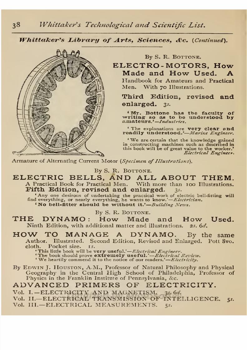
8/20/2019 electrical experiment.pdf
http://slidepdf.com/reader/full/electrical-experimentpdf 312/325
38
Whittaker's
Technological
and
Scientific
List.
Whittaker's
Library
of
Arts,
Sciences,
&c.
{Continued).
By
S.
R.
Bottone.
ELECTRO-MOTORS,
How
Made and
How
Used.
A
Handbook for
Amateurs
and
Practical
Men.
With
70
Illustrations.
Third
Edition,
revised
and
enlarged.
3s.
1
Mr.
Bottone
has
the
faculty
of
writing
so
as
to
be
understood
by
amateurs
.
'
—Industries.
'
The
explanations
are
very
clear
and
readily
understood.'—
Marine
Engineer.
'
We
are
certain that
the
knowledge
gained
in
constructing
machines
such
as described
in
this
book will be
of
great
value
to
the
worker.
Electrical
Engineer.
Armature
of
Alternating
Current
Motor
{Specimen of
Illustrations).
By
S.
R. Bottone.
ELECTRIC
BELLS,
AND ALL
ABOUT
THEM.
A
Practical
Book for
Practical
Men. With
more
than 100
Illustrations.
Fifth
Edition,
revised
and
enlarged.
35.
'Any
one
desirous
of
undertaking
the
practical
work of
electric
bell-fitting
will
find
everything,
or
nearly
everything,
he wants to know.'
—
Electrician.
'
No bell-fitter should
be
without it.
T
—
Building
News.
By
S.
R.
Bottone.
THE
DYNAMO:
How
Made
and
How
Used.
Ninth
Edition,
with additional
matter
and illustrations. 2s.
6d.
HOW
TO
MANAGE
A
DYNAMO.
By
the
same
Author.
Illustrated.
Second
Edition,
Revised
and
Enlarged.
Pott
8vo.
cloth.
Pocket size. u.
'This
little
book
will be
very
useful.'
—
Electrical
Engineer.
'The
book
should
prove
extremely
useful.
—
Electrical
Review.
'
We
heartily
commend
it to
the
notice of
our readers.'
—
Electricity.
By
Edwin
J.
Houston,
A.M.,
Professor
of
Natural
Philosophy
and
Physical
Geography
in
the
Central
High
School
of
Philadelphia,
Professor of
Physics
in the Franklin
Institute
of
Pennsylvania,
&c.
ADVANCED
PRIMERS OF
ELECTRICITY.
Vol.
I.
—ELECTRICITY
AND
MAGNETISM.
35.6^.
Vol.
II.—
ELECTRICAL
TRANSMISSION
OF
INTELLIGENCE.
$s.
Vol.
III.—
ELECTRICAL MEASUREMENTS.
5j.

8/20/2019 electrical experiment.pdf
http://slidepdf.com/reader/full/electrical-experimentpdf 313/325
W/iittaker's
Technological
and
Scientific
List.
39
Whittaker's
Librae
of
Arts,
Sciences,
etc.
{Continued).
By
Sir
David
Salomons, Bart.,
M.A.,
Vice-President of
the
Institution
of
Electrical
Engineers,
&c.
ELECTRIC-LIGHT INSTALLATIONS,
AND
THE
MANAGEMENT
OF
ACCUMULATORS.
A
practical
handbook.
Sixth
Edition,
revised
and
enlarged,
with
numerous
Illustra
tions.
6s.
•
We advise
every
man
who
has
to
do
with installation work
t*>
Study
this
work.'
—
Electrical
Engineer.
'
To
say
that
this
book
is
the best of
its kind
would
be a
poor compliment,
as
it
is
practically
the
only
work on
accumulators that
has
been
written.'
Electrical
Review
'Will
be
found
very
valuable
to those
owning
or
having
charge
of installations.*
Industries
.
By J.
Gray,
B.Sc
ELECTRICAL
INFLUENCE MACHINES:
Con
taining
a Full
Account
of their Historical
Development,
their
Modern
Forms,
and
their
Practical
Construction.
4s.
6d.
'This
excellent
book.'—
Electrical
Engineer.
'
We
recommend
the book
strongly
to
all
electricians.'
Electrical
Plant.
Wbittafcer'6
%ibran>
of
popular
Science.
Square
crown 8vo.
cloth,
2s.
6d.
per
vol.
A
Series of
easy
introductions
to
the
Physical
Sciences,
suitable
for
general
use.
ELECTRICITY
and
MAGNETISM.
By
S.
Bottone.
With
103
Illustrations. 2s.
6d.
GEOLOGY.
By
A.
J.
Jukes
Brdwne,
F.G.S.
With
95
Illus-
trations.
2s.
6d.
'
An
excellent
guide
to the rudiments
of the
science.'—
Atlienaum.
'
The book is a
good
one.'
—
Nature.
PICTORIAL ASTRONOMY.
By
G.
F.
Chambers,
F.R.A.S.
With
134
Illustrations.
Second
Edition,
revised.
2s. 6d.
'
One of the
most
interesting popular
treatises
that
we
have
had
in
our
hands
for
a
long
time.'
—
Daily
Chronicle.
'
An
elegantly
printed
and
profusely
illustrated
work,
which
is
worthy
of
the
author's
reputation.'—
A
thentrum.
LIGHT.
By
Sir
H.
Trueman Wood.
With
85
Illustrations.
2s.
6d.
'
We
have here a
popular
and
interesting
resume of
many
of
the
facts
relat-
ing
to
the
nature
and
properties
of
light.'
—
Nature.
THE PLANT
WORLD
;
Its
Past,
Present,
and
Future.
By
G.
Massee.
With
56
Illustrations.
Second
Edition,
Revised.
2s.
6d.
'
Its
easy
style,
intelligible
language, good
arrangement,
and
many
illustra-
tions, give
it
a
high
rank
among
books of
it?
kind.'—
Scotsman.

8/20/2019 electrical experiment.pdf
http://slidepdf.com/reader/full/electrical-experimentpdf 314/325
40
Whittaker's
Technological
and
Scientific
List.
Whittaker's
Library
of
Popular
Science
{Continued).
MINERALOGY
:
The
Characters
of
Minerals,
their Classification
and
Description.
By
F.
H.
Hatch,
Ph.D.
With
115
Illustrations.
25.
6d.
'
Dr.
Hatch
has
admirably
united
brevity
and
clearness
in his
treatment
of
the
crystallographical
and
physical
characters of minerals.'
—
Nature.
'
We
cordially
recommend this little
book of
Dr.
Hatch's as
one
of
the best that
students could
purchase.'—
Science
Gossip.
PUBLISHED
FIRST
DAY
OF
EACH
MONTH.
Price
2s.
6d.
net.
PHILOSOPHICAL
MAGAZINE,
and
JOURNAL
OF
SCIENCE,
THE
LONDON, EDINBURGH,
AND
DUBLIN.
A
Journal
devoted
to
Physics,
Astronomy,
Mechanics,
Chemistry,
Mineralogy,
and
Applied
Sciences.
Conducted
by
Lord
Kelvin,
LL.D.,
F.R.S.;
G.
F.
Fitzgerald,
M.A.,
Sc.D.,
F.R.S.;
and
W.
Francis,
Ph.D.,
F.S.S.
flfceotcal
Works.
By
C.
J.
S.
Thompson.
THE
CHEMIST'S
COMPENDIUM AND
DIARY.
A
Pocket-book
of Reference
for
Pharmacists,
Assistants,
and
Students.
Blue
cloth.
238
pp.
2s.
6d. net.
'A
veritable
mine
of
useful
information.'
— The Lancet.
'
It
will
undoubtedly
be
extremely
useful to
the
pharmacist.'
British
Medical
Journal.
'
It is
long
since
we
have
come
across
such a
handy
manual.
Every
chemist should
have
this
manual.'
—
Glasgow
Herald.
'
A novel
and
invaluable
book.'
—
Manchester Guardian.
A New
and Revised
{Twelfth)
Edition. Post
Svo.
10s.
6d.
HOBLYN'S
DICTIONARY
OF
TERMS USED
IN
MEDICINE
AND THE
COLLATERAL
SCIENCES.
Re-
vised
and
Enlarged
by
J.
A.
P.
Price,
B.A.,
M.D.
Oxon.,
Assistant-
Surgeon
to the
Royal
Berkshire
Hospital
;
late
Physician
to
the
Royal
Hospital
for Children
and Women.
'
This
well-known
work.'
—
Lancet.
'As a
handy
reference
volume for
the
physician,
surgeon,
and
pharmacist,
it
will
prove
invaluable.'
—
Pha?-»iaceutical
Journal.
'
From
considerable
experience
of
Hoblyn's
Dictionary,
we
are able to
say
that
it
has the
rare
merit
of
supplying
in
almost
every
case what
you
have a
right
to
expect
in
consulting
it.'
—
Glasgow
Medical
Journal.

8/20/2019 electrical experiment.pdf
http://slidepdf.com/reader/full/electrical-experimentpdf 315/325
W
'hit'taker's
Technological
and
Scientific
List.
41
Tenth Edition. Price
12s.
6d.
HOOPER'S PHYSICIANS'
VADE-MECUM: a
Manual of
the
Principles
and
Practice
of
Physic,
with an
Outline
of
General
Pathology, Therapeutics,
and
Hygiene.
Tenth
Edition,
with
Wood
Engravings.
Revised
by
William
Augustus
Guy,
M.B.
Cantab.,
F.R.S.,
F.R.C.P.
;
and
John
Harley,
M.D.
Lond., F.L.S.,
F.R.C.P.,
Physician
to St. Thomas's
Hospital.
A
WORK
FOR
MEDICAL STUDENTS AND
PRACTITIONERS.
By
C.
Gordon
Brodie,
F.R.C.S.,
late
Senior Demonstrator
of
Anatomy,
Mid-
dlesex
Hospital
Medical
School
;
Assistant
Surgeon,
North-West
Lon.
Hospital.
DISSECTIONS
ILLUSTRATED:
A
Graphic
Hand-
book
for
Students
of
Human
Anatomy.
With
73
Coloured
Plates
(mostly
two-thirds
natural
size)
Drawn
and
Lithographed
by
Percy Highley,
and
many
diagrams.
In
I
Vol.
imperial
8vo.
strongly
bound
in
half
buckram,
flexible
back,
plates
mounted on
tape,
2l. 2s.
In Four
Parts:
—
Part
I. THE
UPPER
LIMB.
17
Coloured
Plates,
is.
6d.
„
II.
THE
LOWER
LIMB.
20 Coloured Plates. 10s.
,,
III.
HEAD,
NECK,
AND
THORAX. 20
Coloured
Plates. 10s.
,,
IV.
ABDOMEN.
16
Coloured Plates. 10s.
'
A
book
which will
certainly
make its
influence
felt in
the
teaching
of
anatomy
in this
country.'
—
British
Medical
Journal.
'
The
plates
are
exceedingly
well drawn
and
placed
on the stone.
.
. .
The
explanatory
letterpress
is
clear
and
concise.'
—
The
Lancet.
'
This work
meets
a
distinct
want.'
—
Edinburgh
Medical
Journal.
'The
scheme
is
admirably
carried
out and
the
plates
most
reliable.'
'
This
very
useful anatomical atlas.'
—
Hospital. Guy's
Hospital
Gazette*
'
The student
will
be
in
possession
of an
excellent atlas of
anatomy.'
Medical
Press.
'
Students
will
find
this
an
invaluable
hand-book. The
plates
are
drawn
so
clearly,
and
they
are
so
large
that
the
muscles, vessels,
and nerves of
each
dissection
can
be found
without
any
difficulty.'
—
Nature.
'
They
will furnish to
many professional
men a
very
valuable
work
of
reference.'—
Glasgow
Medical
Journal.
'
No
hospital library
should
be
considered
complete
unless
it contains
at least one
copy
of
this
valuable work.'
—
Nursing- Record.
Super
Royal
4to.
cloth. Price 16s. net.
ATLAS
of
THE
HUMAN
BRAIN
and
DESCRIP-
TION OF
THE
COURSE
OF
THE
NERVE-FIBRES.
By
Dr.
E.
Flatau,
with
Preface
by
Professor
Mendel,
of
Berlin.
Translated
by
Wm.
Nathan,
M.D.,
and
John
H.
Carslaw,
M.D.
By
L.
Klindworth.
STUTTERING,
AND
HOW TO CURE
IT
:
A
Practical
and
Systematical
Hand-book
for
Self-
Instruction
;
containing
an
Improved
Method
of
Respiration
and
the
Gymnastic
of Voice
and
Speech.
333
pages
text,
demy
8vo. With
72
Woodcuts,
and several
thousand
Diagrams.
Cloth,
12s. 6d. net.
By
August
Dittmar.
PROF.
RONTGEN'S
X
RAYS,
and their
Application
in
the
New
Photography,
gd.
net.
'
It
is
a
fair
and correct
review
of
the
history
of
the
subject.'
—
Lancet.

8/20/2019 electrical experiment.pdf
http://slidepdf.com/reader/full/electrical-experimentpdf 316/325
42
W/iittaker's
Technological
and
Scientific
List.
y&ooks
for
^Technological
anfc
flDanual
Graining
Classes,
'THE ENGLISH
SLOYD.'
MANUAL
INSTRUCTION
-WOODWORK.
By
S.
BARTER,
Organizer
and
Instructor of
Manual
Training
in
Woodwork
to the London School Board
and
Organizing
Instructor
to the
Joint
Committee on Manual
Training
in
Woodwork of the
School Board for
London,
the
City
and
Guilds
of London Technical
Institute,
and
the
Worshipful
Company
of
Drapers.
With
a Preface
by
George
Ricks,
B.Sc.
Lond. Illustrated
by
303
Drawings
and
Photo-Engravings.
New
Edition.
Fcap.
4to.
cloth,
js.
6d.
Contents
:
—
Introduction
—
Drawing
—
Timber
—
Tools
—
Bench-work
—
Work-room
and
its
Fittings
—
List
of
Tools
Required,
&c.
The
above Work
covers the
Requirements of
the Examinations
of
the
City
and
Guilds
of
London Institute and
the Science
and
Art
Department
in
the
subject.
Sir
Philip
Magnus
says:
—
'Mr.
Barter,
in his book on
Woodwork,
has
succeeded in
showing,
what is
most
important,
the
educational value
of
manual
training
in school
instruction,
and has
thus
rendered a
great
service
to those
seeking
a
trustworthy
guide
in
the
practical
study
of the
subject.'
J.
H.
Reynolds,
Esq.,
Director
and
Secretary Municipal
Technical
Schools,
Manchester,
says:
—
'One of
the
best,
if
not the
best
book,
that
has
hitherto
been
published
on
this
subject,
whether
English
or
American.'
Professor W.
Ripper,
of Sheffield Technical
School,
says
:
—
'
Mr.
Barter,
by
his
ability, experience,
and
success
as
an instructor
of manual
training classes,
is the
right
man to
write
a
book
on
woodwork,
and
the
book he
has
produced
is
a most
valuable
addition
to our
literature
on manual
training
—
in
fact,
so
far
as I am
aware,
it is
the
most
complete
and
satisfactory
work,
as a
course of
instruction
for
schools,
yet published
in
this
country.'
By
S.
Barter,
Author
of
'
Manual Instruction
—
Woodwork.'
MANUAL
INSTRUCTION
—
DRAWING.
Showing
the
application
of Geometrical
Drawing
to
Manual
Instruction
in
Wood
and
Metal.
To
cover
the
requirements
of the
City
and
Guilds
of London
Examination.
32
plates
with
98
subjects,
cloth.
Foolscap
4to,
y.
6d.
'
The
examples
and illustrations are
admirable,
and
the
work
is a
worthy
companion
of
the
author's
treatise on
Woodwork.'
—
School
Board
Chronicle.
By
CHARLES
G.
LELAND,
M.A.
DRAWING AND
DESIGNING.
In
a
Series of
29
Lessons. With
42
Illustrations.
Second
Edition.
Fcap.
4to.
sewed,
1
j.; cloth,
is.
6d.
'
It
has a
good
equipment
of
plates,
and
the
text
is
full
of
valuable
practical
directions
for
beginners.'—
Scotsman.
'
Mr.
Leland
upholds
the
principle
that
drawing
and
designing
should
go
together,
and
maintains
that
inventive
powers
are
cramped by
the
system
of
teaching
which
requires
a
high
standard
of
manipulative
skill before the
student
is
instructed in
design.
In this
we
entirely
agree
with
him.'
—
Literary
World.
'The book
deserves the
widest
sxxccese.'Scottish
Leader.
'
The
system
is
simplicity
itself.'—
Liverpool
Daily
Post.

8/20/2019 electrical experiment.pdf
http://slidepdf.com/reader/full/electrical-experimentpdf 317/325
Whittakers
Technological
and
Scientific
List.
43
Whittalxer's
liooJcs
for
Manual
Training
(Continued).
By
the Same
Author.
WOOD-CARVING.
With numerous
Illustrations.
Third
Edition.
Fcap.
4to.
5-r.
'An
excellent
manual.'
Morning
Post.
'
An
admirable
little book.'
Builder.
'
Such
patient,
explicit,
step-by-step
teaching
as
Mr.
Leland's
is
indeed
the
only
road to excellence.'
Saturday
Review.
'Avery
useful
book.'
—
Mr.
\V. H.
Howard,
Sec-
retary
to the
Institute
of
British
Wood
Carvers,
and
Instructor
at
King's
College,
London.
'
A
splendid
help
for
Amateurs
and
those
beginning
the
trade.
Without
exception
it
is
the
best book I have
read
at
present.'—
Mr.
T.
J.
Perrin,
Society
of
Arts
Medallist,
Instructor
in
Wood-
carving
at
the
People's
Palace.
'
I
consider
it
the
best
manual
I
have seen.'
—
Miss
Hodgson,
Instructor in
Wood-carving
at Manchester
Technical
School.
Initial Letter
(Specimen
of
Illustrations).
A
Companion
Volume
to
'Wood-Carving,'
by
the
Same
Author.
LEATHER -WORK.
Stamped,
Moulded,
and
Cut.
Cuir-Bouilli, Sewn,
&c.
A
Practical
Manual
for Learners.
With
numerous
Illustrations.
%s.
'A
delightful
addition
to the
series
of
practical
manuals.'
—
Times.
By
the
Same
Author.
METAL
WORK.
Including
Repousse,
Bent
or
Strip
Work,
Cut
Sheet
Metal
Work,
Nail or
Knob,
Wire,
Easy
Silver Ornament and
Chasing
Work.
An
Elementary
Manual
for
Learners.
With
numerous
Illustrations.
$s.
By
the
Same
Author.
PRACTICAL
EDUCATION.
A
Work
on
Preparing
the
Memory,
Developing
Quickness
of
Perception,
and
Training
the
Constructive
Faculties.
Fourth
Edition.
Crown
8vo.
cloth,
6s.

8/20/2019 electrical experiment.pdf
http://slidepdf.com/reader/full/electrical-experimentpdf 318/325
44
Whit
takers
TecJinological
and
Scientific
List.
Whittaker's
Books
for
Manual
Training
{Continued).
By John
Southward,
Author
of
*
Practical
Printing,'
'The
Principle
and
Progress
of
Printing
Machinery,'
'
A
Treatise on
Modern
Typography'
ins
Encyclopedia
Britannica,
&c.
MODERN
PRINTING.
A
Treatise
on
the Science
and
Practice
of
Typography.
I
vol.
8vo.
cloth,
xos.
;
Quarterly
Sections,,
zs. 6d.
each
;
Monthly
Parts,
is.
each.
A
Large-paper
Edition,
limited
to
500
Copies,
crown
4to.
21s.
[In
the
Press,
By
C.
T.
Jacob
1.
THE
PRINTERS
HANDBOOK
OF
TRADE
RECIPES.
With
many
useful
Tables and
an
Index.
Second
Edition.,
Enlarged
and Classified.
Piice
5.?.
QUESTIONS
IN
TYPOGRAPHY,
Set from
i8go
to
1895
inclusive
at the
Examinations
of
the
City
and
Guilds of
London
Institute
for all
Grades.
Paper
cover,
8vo. 6d.
By
Florence
B.
Jack,
Head
Teacher
of
Laundry
Work,
Edinburgh
School of
Domestic
Economy.
LAUNDRY
WORK,
The
Art
of;
Practically
De-
monstrated for use
in
Homes and
Schools.
With
many
Illustrations.
Post 8vo.
2S.
COOKING
FOR
INVALIDS,
The
Art
of;
In
the
Home and the
Hospital.
By
the
same
Author.
Post
8vo. 2s.
By
Mrs.
Charles
Marshall,
Author
of
'
Gas
Cookery.'
GRANDMAMA'S
CAKES: A
Book
of
Recipes.
Fcap.
8vo.
paper
cover,
ij.
'
All
the
recipes
in
'
Grandmama's
Cakes
'
are
genuine
old-fashioned
ones,
and
were-
originally
collected
in
manuscript
form
by
my
grandmother,
who
was
famous
for the
good
things
at
her
table.'
—
From
Preface.
THE
MANUAL
TRAINING
SCHOOL:
ITS
AIMS,
METHODS,
AND
RESULTS,
with
Figured
Drawings
of
Shop
Exercises
in
Wood
and
Metals.
By
C.
M.
Woodward,
Director
ofthe
Manual
Training
School,
Washington
University.
8vo.
cloth,
$s.
net.
INDUSTRIAL
INSTRUCTION.
A
Pedagogic
and
Social
Necessity. By
R.
Sei
del,
Mollis,
Switzerland.
Crown
8vo.
cloth,
2s.
6d.
THE
DURHAM
UNIVERSITY
CALENDAR
and
ALMANAC.
Published
annually
in
January.
Cr. 8vo.
cloth,
15.
6d.
net.
PROGRAMME
OF
TECHNOLOGICAL
EXAMI-
NATIONS
OF
THE
CITY
AND
GUILDS
OF
LONDON
INSTI-
TUTE.
Including
Regulations
for
the
Registration
and
Inspection
of
Classes
in
Technology
and
Manual
Training, Syllabus
of
Instruction
and
Lists of Works of
Reference in
each
Subject,
this
year's
Examination
Questions,
Names of
Teachers of
Registered
Classes,
&c.
Published
annually
in
August.
lod.
net;
post
free,
is.
id.
London:
Whittaker
&
Co.,
Paternoster
Square,
E.C.

8/20/2019 electrical experiment.pdf
http://slidepdf.com/reader/full/electrical-experimentpdf 319/325
INDEX
ACCUMULATORS,
Salomons', 5
s,
and 6s.
Plants,
12s.
Adams'
Joints
in
Woodwork,
is.
Prac.
Trigonometry,
2S. 6d. net ...
Agricultural
Engineering
in
India,
3s.
6d.
Alexander's
Model
Steam
Eng.
,
ios. 6d.
Alkali Makers'
Handbook,
ios. 6d.
Allsop's
Electric
Light Fitting,
5s.
Alternating
Currents,
Blakesley,
5s.
...
Bedell and
Crehore,
ios.
6d.
Experiments,
Tesla,
4s.
6d.
..
Fleming,
2
vols.
25.?.
...
Hospitalier,
3s.
6d.
...
Kapp,
4s.
6d.
...
Alternate
Current
Transf.
Design,
2s. ...
Analysis, Iron,
Blair,
16s.
Steel
Works,
Arnold,
ios.
6d.
Anatomy,
Brodie,
4
parts,
or
1
vol.
Anderson's
Heat,
6s.
Andreoli's
Ozone,
2s.
6d.
...
Arithmetic,
Electrical,
is.
Armature
Windings,
Parshall,
30$.
Drum,
Weymouth,
7s.
6d....
Armorial
Families
5/.
55.
Arnold's
Steel
Works,
Analysis,
10s. 6d.
Artillery,
Modern
French,
50s.
...
Astronomy,
Chambers,
2s. 6d. ..
Atkinson's
Static
Electricity,
6s. 6d.
...
Atlantic
Ferry,
7s.
td. and 2s. 6d.
4-39
27
32
31
'4
12
9
37
7
16
18
21
24
17
iS
13
24
27
B
BALLOONING,
May,
2s. 64.
Badt's
Electrical
Works ...
Bale's
Mod.
Shafting
and
Gearing,
2S.6d.
Barter's
Drawing
Woodwork,
7s.
6d.
...
Battle
of
Port
Said,
is
Bax's
Electric
Lighting,
2s
Beardmore's
Drainage,
5s.
Beaumont's
Woven
Design,
21s.
Steam
Engine
Indicator,
3s
6d.
...
Bedell
and
Crehore's
Alternating
Cur-
rents,
las.
6d.
Bell's
Submarine
Telegraphy,
is. 6d.
...
Telegraphist's
Guide,
is.
6d.
Bennett's
Telephoning,
is.
Bigg's
Electrical
Engineering,
2s. 6d.
...
Black's
First Prin.
of
Building,
3s.
6d.
Blair's
Analysis
of
Iron,
16s.
Blakesley
's
Alternating
Currents, 5s.
...
Bodmer's
Hydraulics,
14s.
—
—
Railway
Material
Inspection
Boiler
Construction,
Cruikshank,
7s.
6d.
Bonney's
Electrical
Experiments,
2s. 6d.
Electro-platers'
Hand-book, 3s.
...
Induction
Coils,
3s.
...
Bookkeeping,
Crellin,
is. 6d.
Key,
2s.
Book
of
Crests,
3/. 3s
Public
Arms,
3/.
3s.
net.
Bom's
Metric
Mesures,
3s.
Botany, Massee,
2s. 6d.
...
Bottone's
Elecl. Instrument
Making, 3s.
Electric
Bells,
3s
Electro-Motors,
3s.
...
Bottone's
Electricity,
2s. 6d.
Electric
Light
Guide,
is
How to
Manage
a
Dynamo,
is. ...
The
Dynamo,
2s. 6d.
Boulnois'
Carriageways,
&c.
5s.
Boult's
Wire
Table, 5s.
3°
2
'5
39
17
13
9
25
27
42
42
15
19
10
9
16
26
26
16
19
19
13
7
6
1
*5
34
35
34
29
30
31
14
39
37
38
38
39
16
38
rAGE
Boyd's
Coal
Pits, 7s.
6d.
.. ...
...
13
Boyd's
Petroleum,
2s.
...
...
...
30
Brain,
Flatau's Atlas
of,
16s.
net ...
41
British
Locomotives,
Cooke,
7s.
6d. ... 11
Brodie's
Dissections,
2/.
2s.
...
...
41
Browne's (Jukes) Geology,
2s.
6d.
...
39
Bucknill's Submarine
Mining,
12s. 6d.
15
Building,
Black,
3s.
6d.
...
...
...
19
C_y
AB
IN
ET
Making,
5s 36
Cakes,
Marshall,
is.
44
Calculus,
Diff.
and
Intg.,
3s.
6d.
...
31
Cambrian
Minstrelsie,
2/. us.
...
...
31
Carriage
and
Footways
Construction,
5s.
20
Central
Station
Bookkeeping,
10s.
6d....
17
Chambers'
Astronomy,
2s. 6d.
...
...
39
Chemistry,
Elementary Practical,
9rf.net 31
Chemist's
Compendium,
2s.
6d.
net
...
40
City
and
Guilds
Examin.
Programme,
lod.
net;
is.
jrf.
post
free
...
...
44
Coal
Mining,
Walker,
2s.
6d.
24
Coal
Pits, Boyd, 7s.
id.
13
Colliery Lighting,
2s. 6d.
...
...
27
Colour
in Woven
Design,
21s.
...
...
9
Cooke's
Locomotives,
-js.
6d.
... ...
11
Cooking, Jack,
2s
44
Cox's
Cont.
Current
Dynamos,
7s.
6d. 16
Crehore
and
Bedell's
Alternating
Cur-
rents
of
Electricity,
10s. 6d. ...
... 16
Crellin's
Bookkpg.,
is. 6d.
;
Key,
2s.
net
29
Crests,
Fairbairn, 3/.
3s
30
Crosby
and
Bell s The
Electric
Railway,
10s. 6d.
...
...
...
...
...
17
Cruikshank's
Boiler
Construction, 7s.
td.
-55
Cunarders
(New),
6s
13
DAVIES'
Guide to
Mining
Exams.
2
parts,
is. 6d. each
Dawson's
Electric
Railways, 30s.
Denning's
Cabinet
Making,
5s
Designing,
Leland,
is
Dictionaries,
Technological
Dictionary
of Medical
Terms,
10s. 6d.
...
Discount
Tables,
is.
Dissections
Illustrated,
Brodie
\
1 Vol.
2I.
2S.,
or (
Part
I.,
8s. 6d.
Part
II„
ios.
(
'
Part
III,,
10s.
Part
IV.,
ios.
)
Dittmar's
Rontgen Rays,
gd.
net
Drainage,
Beardmore,
5s.
Nadieine,
is
Draughtsmen's
Work,
is. 6d.
Drawing
and
Designing,
is.
Barter
...
Dredge's
Chicago
Exhibition,
3/.
3s.
...
Electric
Illumination. Vol.
II.,
30s.
Modern
French
Artillery,
50s.
Pennsylvania
Railway, 52s.
6d.
...
Drum
Armatures, 7s.
6d.
Durham
University
Calendar,
is.
6d. net
Dynamo,
Bottone,
2s. 6d.
Building,
Walker,
2s.
Parkhurst, 4s.
6d.
Gibbings,
is.
... ...
Hawkins
and
Wallis,
ios. 6d.
How
to
Manage,
Bottone,
is.
Machinery,
Hopkinson,
5s.
Strange
History,
is.
Tenders,
H.
B.
Badt,
4s.
6d.
&c,
Kapp,
ios. 6d. ...
23
14
36
42
29
40
26
41
4i
10
10
36
42
42
13
J
3
15
16
21
44
38
27
17
26
2
38
37
24
»5
20
8/20/2019 electrical experiment.pdf
http://slidepdf.com/reader/full/electrical-experimentpdf 320/325
4
6
Whittakers
TecJinological
and
Scientific
List,
PAGE
.CdUCATION,
Practical,
6s
Egleston's
Metallurgy,
2
vols.,
31s.
6a .
ea.
Electric
Bell
Hangers,
H.
B.,
4s.
6d.
...
Bells,
Bottone,
3s.
...
Illumination,
by Dredge
and
others,
30s.
...
Influence
Machines,
4s.
6d.
Lamps,
Fleming,
ys.
6d.
..
Lamps,
R.
Kennedy,
2s. 6d.
Lamps,
Ram,
js.
6d.
Light
Cables,
Russell,
7s.
6d.
Light
Carbons,
is. 6d.
Light
Fitting.
Allsop,
5.?
Light
Installation, Salomons',
3
vols.
Vol.
I.,
Accumulators,
55-.
Vol.
II.,
Apparatus,
js.
6d.
Vol.
III.,
Ap-
plication,
5s
Light
Installations,
Salomons',
1
vol.,
6s.
..
Light
and
Power,
Guy, 5s.
Lighting,
Bax,
2s
Lighting
of
Colliery,
2s. 6d.
Lighting,
Guide
to,
is.
Lighting
Specifications,
6s.
Lighting,
Maycock,
6s
Lighting,
Segundo,
is.
Lighting,
T.
C.'s
Handbook,
is.
...
Motive
Power,
Snell,
10s.
6d.
Railways,
Crosby
and
Bell,
10s.
6d.
Railways,
Hering,
5s.
Railways
and
Tramways,
Dawson,
3°^
Traction,
Reckenzaun.
10s.
6d.
...
Transformers,
Kapp,
6s
Transformers,
Weekes,
2s....
Transmission,
Badt
...
Transn.
of
Energy,
Kapp,
10s.
6d.
Wiring,
Badt,
4s.
6d.
Wiring,
Noll,
6s
Wiring
Tables,
2s. 6d.
Electrical
Engineering,
4s.
6d.
...
Engineering,
Biggs,
2s. 6d.
Engineering
Formulas,
js.
6d.
Engineering,
Kapp
and
others,
42s.
Energy,
Kapp,
10s.
6d.
Energy,
Plante,
12s.
Engineers'
Tables,
&c,
2s.
Experiments,
Bonney,
2s.
6d.
Distribution,
Kilgour,
10s. 6d.
...
Instrument
Making,
3s
Lab.
Notes,
Fleming,
12s. 6d. net
Measurements,
Arithmetic
of,
is.
Notes, Kennelly,
6s. 6d.
Terms,
Houston,
21s.
Electricity,
Alternating
Currents
of,
Bedell
and
Crehore,
10s. 6d. ...
Alterng.
Currents
of,
Blakesley,
5.J.
Fleming,
2
vols.,
25.?.
Kapp,
4.J.
6d. ...
Experiments,
Tesla,
4s.
6d....
Forbes,
is.
6d....
100
years
ago, 4s.
6d.
Portative,
Niblett,
2s. 6d.
Houston,
3
vols.
13s.
6d. ...
a»d
Magnetism,
Bottone,
2s. 6d.
and
Magnetism,
Maycock.
2s. 6d.
-
in our
Homes, Walker,
6s....
Primers,
3d.
each
Static,
Atkinson,
6s. 6d.
Electro-chemistry,
Gore,
2s.
43
H
25
38
39
20
24
25
7
26
PAGE
Electro
-
magnetic
Theory,
Heaviside,
Vol.
I.,
12s. 6d. 22
Electro-motors,
Bottone,
3^.
... ...
3S
Electro-platers'
H.B.,
Bonney,
3s.
...
35
Electrolytic
Separation,
Gore,
10s. 6d.
21
Engineer
Draughtsmen's
Work,
is. 6d.
36
Fitting, $s.
_
34
English
Minstrelsie,
4/.
...
...
...
30
Ewing's
Induction,
10s. 6d.
...
.
22
Explosives,
Guttmann,
2
vols.,
2/. 2s.
...
4
39
19
19
26
16
iS
33
24
iS
25
17
17
14
19
25
3
25
25
26
16
19
22
19
3
27
27
34
18
37
21
27
20
17
16
7
21
17
18
18
17
18
38
39
33
37
22
17
21
TAIRBURN'S
Crests,
2
vols., 4I.
4s
Findlay's
English
Railway,
js.
6d.
Fitting,
Horner, 5s.
Electric
Light,
Allsop,
5s
Fitzgerald's
Nav.
Tactics,
is.
Flatau's
Atlas of Human
Brain,
16s.
ret
Fleming's
Transformers.
Vol.
I.,
12s.
6d.
Vol
II.,
12s. 6d.
Electric
Lamps,
js.
6d.
Electric
Lab.
Notes,
12s. 6d. net
Fletcher's
Steam-jacket,
-js.
6d.
Foden's
Mechanical
Tables,
is. 6d.
Forbes'
Electric
Currents,
2s. 6d.
Forestry,
Webster,
3s.
6d.
Formulae
for Electrical
Engineers,
ys.6d.
Forth
Bridge,
5s.
...
Foster's
Central Station
Bkpg.,
10s.
6d.
Fox-Davies'
Book
of
Crests,
4/.
4s.
Armorial
Families,
5/.
5s.
...
CjASEOUS
Fuel,
is.
6d.
Gatehouse's
Dynamo,
is....
Gearing,
Helical,
7.?.
6d.
..
Geipel
and
Kilgour's
El.
Formulas,
js.6d.
Geology,
Jukes-Browne,
zs.
6d....
German
Technological
Dictionary,
5$...
Gibbings'
Dynamo
Attendants,
is.
Godfrey's
Water
Supply
Gore's
Electro-Chemistry,
2s
Electro-deposition,
is.
6d.
Metals,
10s.
6d.
_
Gray's
Influence
Machines,
4s.
6d.
Griffith's
Manures,
7s.
6d.
Guttmann's
Explosives,
2
vols.,
2/.
2s...
Guy's
Electric
Light
and
Power,
5s.
..
R
30
12
34
37
14
41
21
20
21
6
29
18
28
22
15
17
30
30
27
25
8
22
39
29
26
20
21
18
21
39
10
4
19
_
lATCH'S
Mineralogy,
2s. 6d.
Haulbaum's
Ventilation,
is
Hawkins' and
Wallis's
Dynamo,
10s.
6d.
Heat
Engines,
Anderson,
6s.
_
Heaviside's
Electro
-
magnetic
Theory.
Vol.
I.
12s.
6d.
...
Helical
Gears, 7.J.
6d.
Hering,
Electric
Railways,
s-r
Hertz'
Work,
Lodge,
2s.
6d.
net.
Hewitt
and
Pope's
Elem.
Chem.,
gd.
net
...
Highways
Management,
Hooley,
is.
...
——
Bridges,
Silcock
Hobbs'
Electrical
Arithmetic,
is.
_
...
Hoblyn's
Medical
Dictionary,
10s. 6d.
Holtzapftel's
Turning,
5
vols,
5/.
gs.
...
Hooley's
Highways,
is.
...
Hooper's
Physician's
Vade
Mecum,i2^.6«'.
Hopkinson's
Dynamo
Machinery,
5J.
...
Horner's
Mechanical
Works
...
32,
33,
34
Hospitalier's
Poly.
Altg.
Currents, 3s.
6d.
24
Houston's
Electrical
Terms,
21s.
...
17
40
24
17
22
3i
20
20
27
40
28
20
41
37

8/20/2019 electrical experiment.pdf
http://slidepdf.com/reader/full/electrical-experimentpdf 321/325
Whittaker's
Technological
and
Scientific
List.
47
Hurter's
Alkali Makers'
Hndbk,
ios.6d.
Hutton's
Mathematical
Tables,
12$.
...
Hydraulic
Motors, Bodmer,
14s.
IMRAY
and
Biggs'
Mechanical
Engi-
neering,
3s.
6d....
...
Incandescent
Lamp,
Ram,
7$.
6d.
Induction
Coils, Bonney,
3.?.
Industrial
Instruction,
Seidel,
2s. 6d.
...
Inventions,
How to
Patent,
2s. 6d. net
Iron
Analysis,
Arnold,
10s. 6d.
...
Analysis,
Blair,
i6.r...
and
Steel,
Skelton,
5.?.
Ironfounding,
4s
PAGE
9
r
6
J
ACK'S
Cooking,
is
Laundty
Work,
2s. ...
Jacobi's
Printer's
Handbook,
$s.
Jones'
Refuse
Destructors,
5$.
..
Jukes-Browne's
Geology,
2s.
6d.
K
^APP'S
Alternating
Currents, 4.5.
6d.
Dynamos,
&c,
10s. 6d.
Elect.
Transmis. of
Energy,
10s.
6d.
Transformers,
6s.
Kennedy's
Electric
Lamps,
2s.
6d.
Kennelly's
Electrical
Notes,
6s.
6d.
Kilgour's
Electrical
Formulae,
7s.
6d.
...
Electrical
Distribution,
10s.
6d. ...
Kingdon's
Applied
Magnetism,
7s.
6d.
Klindworth's
Stuttering,
12s.
6d.
.Laundry
Work,
jack,
2i
.
...
Leather
Work, Leland's,
5.?.
Leland's
Wood-carving,
$s.
Metal
)
Work,
5^.
Leather
Work, $s.
'
Drawing
and
Designing,
is.
and f
is.
6d.
Practical
Education,
6s.
)
Lens
Work
for
Amateurs,
Orford,
3^..
...
Lenses,
Photographic,
Traill
Taylor,
3-r.
6d. ...
...
Library
of
Art,
Sciences,
&c.
'9
25
34
44
29
2
13
r
9
34
44
44
44
20
39
17
20
24
20
22
18
24
41
44
43
42,
43
of
Great Industries
•
•
35
...
34
1
1
e(
seq.
of
Pop.
Science,
2s.
6d.
per
vol.
Light,
Sir
H.
T.
Wood,
zs. 6d.
...
Lightning
Conductors,
Lodge,
15J.
Lockwood's
Telephonists,
45.
6d.
Lloyd's
Mine
Manager,
is.
6d.
...
Locomotives,
Cooke,
7s.
6d.
Reynolds,
2s. 6d.
Lodge's Lightning Conductors,
Hertz,
2s.
6d.
net
Lukin's
Turning
Lathes,
3.1.
Screws, 3.5-.
Lunge
and
Hurter's
Alkali Makers'
Handbook,
10s.
6d.
1
5
j.
M.
ACLEANS
Physical
Units,
2s.
6d.
Maginnis'
Atlantic
Ferry,
7s.
6d.
and
2S. 6d.
Magnetic Induction,
Ewing,
ioj.
6d.
...
Magnetism,
Kingdon,
ys.
6d
Manchester
Ship
Canal,
3.?.
6d.
Manual
Instruction and
Training
42,
43
Manures,
Griffiths, 7s.
6d.
Marine
Engineering,
Maw,
3/.
Marshall's
Cakes,
is
Martin's
Structures,
4^
Mason's
Sanitation
Massee's,
The
Plant
World,
zs. 6d.
...
Mathematical
Tables,
12$.
3'J
39
7
18
24
n
19
7
22
27
27
13
22
24
15
4t
10
H
44
14
20
39
16
PAGE
14
•
9
.
26
26
33
33
29
19
40-
18
33
43
Maw's
Marine
Engineering,
3/....
May's
Ballooning,
2.J.
6d.
Belting
Table,
2s. 6d.
Electric
Light
Plant,
2s.
6d.
Maycock's
Electr.
and
Magnet.,
2s.
6d.
Electric
Lighting,
6s.
Mechanical
Tables,
is.
6d
Eng.,
Imray
and
Biggs, 3^.
6d. ...
Medical
Terms,
Hoblyn,
10s. 6d.
Merrill's El.
Lighting
Specifications,
6.?.
Metal
Turning, 4s.
Work,
Leland,
$s.
...
Metallurgy,
Gold,
315.
6d. Silver
and
Mercury, 31s.
6d.
Egleston
...
Metric
Measures,
Born,
3.?.
Middleton's
Surveying,
\s.
6d.
...
Mill
Work,
Sutcliffe,
21s
Mine
Manager,
Lloyd,
is.
6d.
...
Ventilation,
Tate,
6d.
Halbaum,
is.
...
Mines
(Fiery)
Management
Mining
Arithmetic,
W.
Tate,
6d.
Examinations,
Davies,
2
Parts,
is.
6d.
each
Student's
Examples,
W.
Tate,
6d....
Students'
Handbooks, 4
Parts,
6d.
each
Mineralogy,
Hatch,
2s.
6d.
Minstrelsie,
English,
8
vols.,
4/. Scots,
6
vols. 2/.
us.
Cambrian,
2/.
us.
30,
31
Mitton's
Fiery
Mines,
is. ...
...
24
Model
Steam
Engine Making,
10s.
6d.
12-
14
2
8'-
24
23-
24
24
23
23
23
23
40.
I\L
ADIEINE,
Drainage,
is
Naval
Tactics,
Fitzgerald,
is.
...
Secondary
Batteries,
5.9.
...
Niblett's
Electricity,
2s. 6d.
Nicholl's
Agr.
Engg.
in
India,
3s.
6d.
.
Noll's
Wiring,
6s
O,
PTICAL
Instruments,
Orford
...
Optics
of
Photography, 3s.
6d.
...
Orford's
Lens
Work,
3.?.
...
Modern
Optical
Instruments
Ozone,
Andreoli,
2s.
6d.
...
PARKHURST'S
Dynamo
Building,
4s.
6d.
...
Parshall's Armature
Winding,
30s.
Patenf'ng
Inventions,
2s. 6d. net
Pattern
Making, 3s.
6d. ...
Petroleum,
Boyd,
2s.
Philosophical
Mag.,
Monthly,
2s.6d.TizX.
Photographic
Lenses,
Taylor,
3s.
6d.
...
Physician's
V.M.,
12J
6d.
Physical
Units,
Maclean,
2s.
6d.
Pickworth's
Slide
Rule,
2s.
Plant
World, Massee,
2s.
6d.
Plante's
Electric
Storage,
12s.
Ponce de Leon's
Spanish
Tech.
Vol
I.,
36s.
Vol.
II.,
32s.
...
Poole's
Telephone
Handbook, 5s.
Practical
Education,
6s.
...
Preece's
Telephony,
15s.
..
Price's
Hoblyn's
Dictionary,
io.j.
6d.
Primers of
Electricity, 3d.
each
...
Printer's
Handbook,
Jacobi,
5s.
Printing,
Southward,
10s.
Pruning,
Des
Cars,
2s.
6d.
Public
Arms,
3/.
3s.
Diet.
V^UADRUPLEX,
Maver,
6s.
6d.
H
18
18
14
25
35
35
35
35
24
17
21
29-
32
3°
40
35
41
20
26
39
27
29
36
43=
I
40
22
4+
44
28
31
7

8/20/2019 electrical experiment.pdf
http://slidepdf.com/reader/full/electrical-experimentpdf 322/325
48
Whit
taker's
Technological
and
Scientific
List.
R
AILWAY
7s.
td.
Management,
Findlay,
Material
Inspection,
Bodmer
Pennsylvania,
52s.
td.
Ram's
Incandescent
Lamp,
7s.
td.
Reckenzaun's
Electric
Traction,
10s.
6d.
Refuse
Destructors,
Jones,
5s
Repousse,
Leland,
5s.
.Reynolds'
Locomotive,
2s.
6d.
...
Rontgen's
X
Rays,
gd.
net
'Russell's
Electric
Cables,
7.?.
(3d.
T. C.'s
Hndbk.
Elec.
Lighting,
is.
SALOMONS'
Electric
Light
Installa-
tion,
6.?.
Electric
Light.
Vol.
I.,
Accumu-
lators, 5.?.
Vol.
II., Apparatus,
7s.
6d.
Vol.
III., Applications,
5s.
Sanitary
Drainage
Sanitation,
Mason
Savage's
Sewage
Disposal,
5s.
...
Scholl's
Phraseological
Dictionary,
Eng.,
Ger.,
Fr.,
and
Span.,
21.?
Scots
Minstrelsie,
2/.
in.
Screws
and Screw
Making,
3s.
...
Screw
Propulsion,
15s
Segundo's
Dom.
Elec.
Lighting,
is.
Seidel's
Industrial
Instruction,
2s.
6d....
Sewage
Disposal,
Savage, 5s
Treatment,
6s.
Shafting
and
Gearing, Bale,
2s.
td.
Ships'
Resistance,
15s
Silcock's
Highway
Bridges
Skelton's
Iron
and
Steel, 5s
Slater's
Sewage
Treatment,
6s. ...
Slide
Rule,
Pickworth,
2s.
Sloyd,
English, 7.?.
td
Smith's
Cable
Traction,
5s
How
to
Patent,
2s. td.
net...
Wire,
7s.
td.
...
Snell's
Electric
Motive
Power,
10s.
td.
Southam's
Elect.
Engineering,
4s.
td....
Southward's
Mod.
Printing,
10s.
Spanish
Techn.
Diet.,
2
vols.,
68s.
Specialists'
Series
.. ... ... ...
1
Steam
Engine
Indicator,
3s.
6d.
...
21
Jacket,
Fletcher,
7s.
td. ...
...
6
Locomotives,
Cooke,
ys.
td. ...
n
Model,
Alexander,
10s.
td.
...
12
Power
and
Mill
Work,
Sutcliffe,
21s
8
Steamships,
Atlantic,
ys.
td. and
2s.
td.
13
Steel Works
Analysis,
Arnold,
10s. td.
2
Stevenson's
Trees
of
Commerce,
3s.
td.
29
Structures, Martin, 4s
14
Stubbs'
Telephony, 15s
1
Stuttering,
Klindworth,
12s.
td. ...
41
Submarine
Cable
Laying,
12s.
td. ...
25
Mining,
12s.
td.
15
Telegraphy, Bell,
is. td.
...
...
26
Sugar
Machinery,
$s
27
Surveying,
Middleton,
4s.
td. ... ... 2
Sutcliffe's Steam
Power and Mill
Work,
T,
...
16
25
'9
19
43
20
4i
7
18
4
10
20
20
27
8
24
44
20
10
27
8
20
J
9
10
26
42
15
29
15
25
16
44
29
ATE'S
Mining
Books
23
Taylor's Optics
of
Photography, 3s.
td.
35
PAGE
Taylor's
Resistance
of
Ships,
15s.
... 8
Technological
Dictionaries
29
Telegraphist's
Guide,
Bell,
is.
td.
..
26
Telephone
Handbook, Poole, 5s.
..
36
Webb,
4-f.
td.
...
... ...
25
Telephoning,
Bennett,
is.
16
Lock
wood, 4s.
td.
... ... ... 18
Telephony,
Preece,
15s.
... ...
1
Tesla's
Experiments,
4s.
td.
...
...
18
Thames
Bridges,
7
parts,
5s.
each
..
14
ThompsonVChernist'sCompdm.2s.6</.net
40
Thwaite's
Gaseous
Fuel,
'is. td.
...
27
Timber
Merchant's
Vade
Mecum, 4s.
...
28
Torpedo,
Autobiography
of
a,
2s.
... it
Tower
Bridge
Tuit,
5s.
..
15
Traction,
Cable
or
Rope,
5s.
...
...
15
Electric,
10s.
td.
...
... ...
19
Trade in Far
East,
Wakefield's,
7s.
td.
11
Transformers, Kapp
..
...
...
1
Tree
Pruning,
Des
Cirs,
2s. td.
...
28
Trees of
Commerce,
Stevenson,
3s.
td.
29
Trigonometry
(Prac),
Adams,
2s. td.
net
31
Tuit,
Tower
Bridge,
5s.
..
15
Turbines
and
Pressure
Engines,
14s.
... 6
Turning,
&c, Holtzapffel,
5
vols.
5L
gs.
28
Turning
Lathes,
Lukin,
3s.
...
...
27
Metal,
4s.
33
Typography
Questions,
td.
44
see
Jacobi
and Southward.
WAKEFIELD'S
Trade
in Far
East
7
s. td.
11
Walker's
Coal
Mining,
2s. td.
...
...
24
Colliery
Lighting,
2s.
td.
27
Dynamo Building,
2s. ...
...
27
Electricity,
ts.
37
Electric
Engineer's
Tables,
2s.
...
27
Wallis's
Dynamo,
10s. td.
...
...
2
Wallis-Tayler's
Sugar
Machine, 5s.
...
27
Water
Supply,
Godfrey
20
Webb's
Telephone
Handbook,
4s.
td. ..
25
Webster's
Practical
Forestry,
3s.
td.
...
28
Weekes'
Transformer
Design,
2s.
... 18
Wershoven's
German
Technological
Dic-
tionary,
5s.
..
...
...
...
29
Westhofen's
Forth
Bridge,
5s
15
Weymouth
Drum
Armatures,
7s.
td. ...
21
Whittaker's
Library
of
Popular
Science,
6
vols. 2S.
td. each
39
Library
of
Arts,
&c
32
Specialists'
Series
...
...
...
1
Wiley's
Yosemite, 15s.
...
... ...
15
Wilkinson's
Electrical
Notes,
6s.
td.
...
20
Cable
Laying,
12s.
td.
... ...
25
Wire, by
Bucknall
Smith,
7s.
td.
...
15
Table,
Boult,
5s
22
Wiring Tables,
2s.
td.
26
Wood's Discount
Tables,
is
26
Light,
2s.
td.
39
Wood
Carving,
Leland,
5s.
_
43
Woodward's
Manual
Training,
5s.
...
44
Woodwork,
Barter,
7s.
td.
4
2
Joints,
Adams,
is
•••
3
2
Woven
Design,
Beaumont,
21s
9
Wyatt's
Diff.
and
Integ.
Calculus,
y.td. 31
Y
OSEMITE,
Alaska,
&c,
Wiley,
15s.
15

8/20/2019 electrical experiment.pdf
http://slidepdf.com/reader/full/electrical-experimentpdf 323/325

8/20/2019 electrical experiment.pdf
http://slidepdf.com/reader/full/electrical-experimentpdf 324/325

8/20/2019 electrical experiment.pdf
http://slidepdf.com/reader/full/electrical-experimentpdf 325/325
PLEASE
DO
NOT
REMOVE
CARDS
OR
SLIPS
FROM
THIS
UNIVERSITY
OF TORONTO
LIBRARY