electrical equipment of industrial machinery exported … · 2 electrical equipment of industrial...
TRANSCRIPT

White PaperMachinery Equipment for North America www.eaton.eu
Electrical equipment of industrial
machinery exported to North America
White Paper
Dipl.-Ing. Wolfgang Esser
Learning from the good, and bad,
experience of others
WP027007EN.indd 1WP027007EN.indd 1 30.03.15 15:3630.03.15 15:36
2
Electrical equipment of industrial
machinery exported to North America Learning from the good, and bad, experience of others
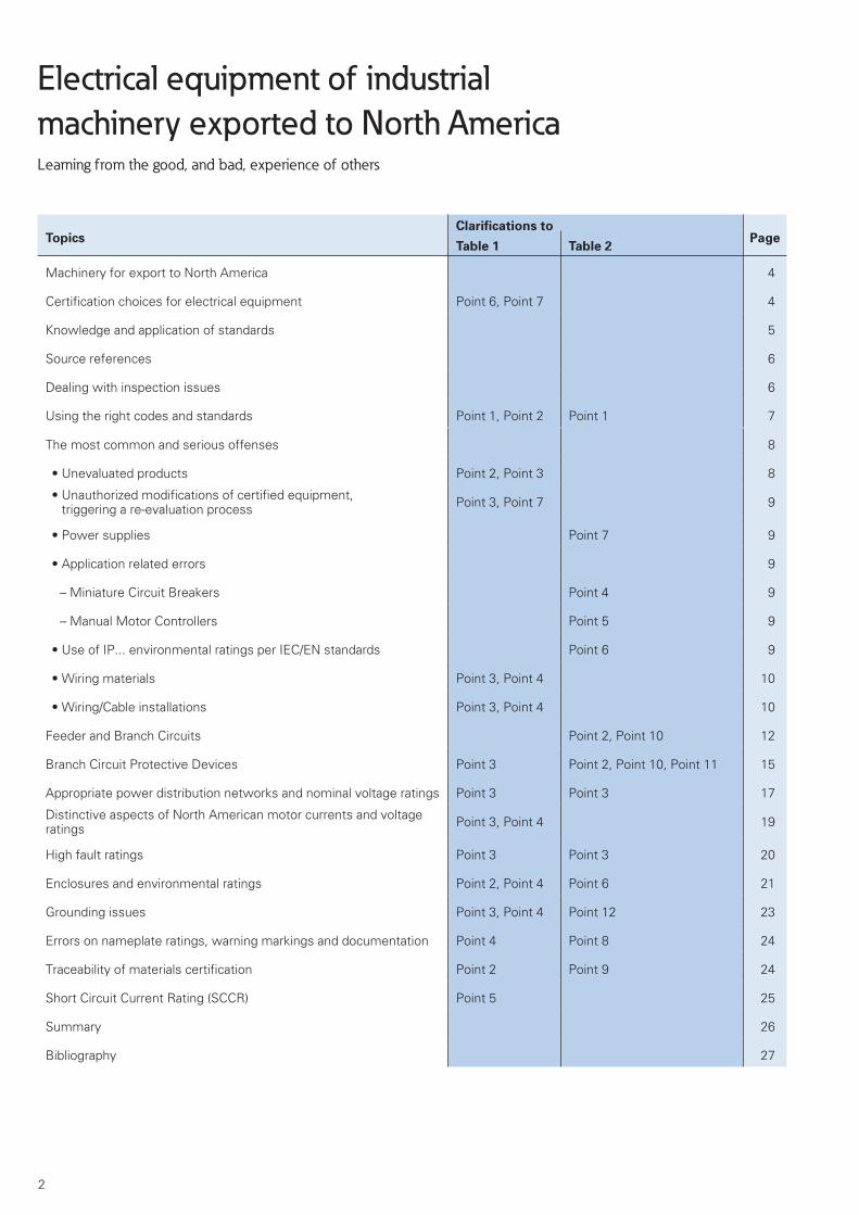
TopicsClarifications to
PageTable 1 Table 2
Machinery for export to North America 4
Certification choices for electrical equipment Point 6, Point 7 4
Knowledge and application of standards 5
Source references 6
Dealing with inspection issues 6
Using the right codes and standards Point 1, Point 2 Point 1 7
The most common and serious offenses 8
• Unevaluated products Point 2, Point 3 8
• Unauthorized modifications of certified equipment, triggering a re-evaluation process Point 3, Point 7 9
• Power supplies Point 7 9
• Application related errors 9
– Miniature Circuit Breakers Point 4 9
– Manual Motor Controllers Point 5 9
• Use of IP... environmental ratings per IEC/EN standards Point 6 9
• Wiring materials Point 3, Point 4 10
• Wiring/Cable installations Point 3, Point 4 10
Feeder and Branch Circuits Point 2, Point 10 12
Branch Circuit Protective Devices Point 3 Point 2, Point 10, Point 11 15
Appropriate power distribution networks and nominal voltage ratings Point 3 Point 3 17
Distinctive aspects of North American motor currents and voltage ratings Point 3, Point 4 19
High fault ratings Point 3 Point 3 20
Enclosures and environmental ratings Point 2, Point 4 Point 6 21
Grounding issues Point 3, Point 4 Point 12 23
Errors on nameplate ratings, warning markings and documentation Point 4 Point 8 24
Traceability of materials certification Point 2 Point 9 24
Short Circuit Current Rating (SCCR) Point 5 25
Summary 26
Bibliography 27
WP027007EN.indd 2WP027007EN.indd 2 30.03.15 15:3630.03.15 15:36

3
Notable differences in the rules governing the export of IEC based electrical equipment and machinery to North
America
1. – Use of North American based electrical codes and product equipment standards,
– attention to additional regional and locally enforced regulations which may apply.
2. – Use of equipment certified by NRTLs,
Components must be certified to the applicable product standards and applied properly per the electrical codes.
3. – Certified components must be selected, sized, combined and applied per the locally enforced codes and standards,
– Component combinations, e.g. motor starters, must be tested and submitted as complete assemblies by the manufac-turer in order to achieve certified high fault short circuit ratings,
– Any application limitations related to the equipment must be taken into consideration during the planning stages,
– Certified components and combinations cannot be physically altered or changed in any form,
– Applicable wiring and installation requirements outlined in locally enforced electrical codes must be strictly followed.
4. – Local market practices and conventions peculiar to North America, which can in some cases markedly differ from cus-tomary IEC practices, must be taken into consideration.
5. – The overall short circuit current rating (SCCR) of industrial control panels must be determined and be part of the control panel nameplate ratings.
6. – The need to establish whether the electrical assembly is best certified initially by a NRTL, and at which location.
– If applicable, obtain NRTL certification for the manufacturing facility.
7. – The machine and its associated electrical equipment will be inspected locally by the AHJ- Authority Having Jurisdiction – who ultimately will approve, or reject, the assembly,
– necessary changes can often only be carried out by locally based North American contractors,
– Changes to an assembly would likely result in a re-evaluation and re-labeling by a NRTL for approval by the AHJ.
Codes = National Electrical Code (NEC), USA, Canadian Electrical Code (CEC), CanadaNRTL = Nationally Recognized Testing Laboratories, e.g. UL, CSA, ETL IntertekHigh Fault Ratings = optimized test results, e.g. to achieve higher SCCR values
Table 1: The procedures governing the design, construction and installation of electrical equipment for machinery destined for export to
North America can be markedly different from those which apply in countries predominantly served by IEC standards. The major differ-
ences can be generally summed up by the 7 points indicated above. Refer to UL508A, Table SA1.1 for further information on applicable
standards.
12 Red Flags. Errors that are most commonly caught by inspectors from European based NRTLs.
1. Designing to the wrong standards
2. Improperly sized electrical clearances in the feeder circuit
3. Improper selection and sizing of components
4. Use of UL 1077 type supplementary protectors instead of proper branch circuit protective devices
5. Use of UL 508 type manual motor controllers instead of proper branch circuit protective devices
6. Environmental rating issues with enclosures
7. Power supplies (Recognized Components instead of Listed Components, industrial devices rather than Class 2 certified equipment)
8. Errors in nameplates, wiring diagrams and warning markings
9. Traceability of certification not possible (e.g. for wiring materials)
10. Improper selection of protective devices for adjustable speed drives
11. Transformer protection not meeting code requirements
12. Grounding/Earthing issues Source: UL Deutschland, ETL Intertek Deutschland
Table 2: Errors that are often caught by NRTL inspectors when evaluating „Industrial Control Panels for Machinery” designed to meet
the North American UL 508A und NFPA 79 standards. AHJs are regularly confronted with machinery related inst allation violations out-
side the panel as well, or with missing or insufficient environmental ratings on door mounted components and enclosures. If a panel
isn’t evaluated first by a NRTL, then a good portion of the above mentioned errors are likely to be flagged by the AHJ.
WP027007EN.indd 3WP027007EN.indd 3 30.03.15 15:3630.03.15 15:36

4
Machinery for export to North
America
The volume of industrial machinery exported to North America (mostly the US and Canada) from Germany, Europe and the rest of the IEC world1 is quite considerable. The positive trend has been especially noticeable in the area of innovative and technologically sophisticated machinery originating out of Germany.
Whereas electrical assemblies in the majority of countries around the world are primarily governed by IEC standards, the prevalent codes and standards in North America (NEC2, CEC3, UL 508A4, NFPA795), to which electrical equipment must comply, are still markedly different from the IEC standards in many respects. Market conventions [1] and customer sensibilities in North America also remain distinct and divergent in many ways from those encountered in the IEC world. Unfortunately, these habits and customs are largely undocumented and must often be laboriously extracted from passages in codes and standards that are difficult for foreigners to decipher. The fact that the documentation is solely formulated in English, or rather, in Americanized English, can be a further handicap to non-native speakers from foreign countries. This author has made a point of repeatedly describing these peculiar market habits and customs in many other technical papers under the general topic of export[2] in order to better familiarize readers with these concepts . Being confronted with unexpected market differences through costly mistakes and/or red-tagging is not the most efficient and appropriate way to go about the export business. It makes good sense for this reason to closely study and analyze the errors that exporters often make when dealing with the specialized requirements of the North American market. The primary goal of
1 IEC = International Electrotechnical Commission2 NEC = National Electrical Code = NFPA 703 CEC = Canadian Electrical Code4 UL 508A = Standard for Industrial Control Panels5 NFPA 79 = Electrical Standard for Industrial
Machinery
this paper is thus to enable exporters to get a jump on eliminating potential setbacks right from the start.
A North Americanized version of a machine and control panel6 from various machinery manufacturers involved in the export trade will tend to vary from make to make, and reflect either a lack of knowledge of the specialized requirements of that market or an unwillingness, or lack of capability, in taking the necessary steps to bring their equipment in conformity with locally applicable codes and standards. Space saving component designs and technologically modern solutions, combined with European advances in the field of functional safety, are important reasons why German and European made machinery equipment designs are in such demand in North America.
The electrical equipment portion of industrial machinery alone features a particularly large value added and differentiation potential. A significant percentage of exported machinery is fully automated. Many of our clients are internationally renowned as technological leaders in their field and, accordingly, demand for their products globally is high. Still, in spite of the state-of-the-art technology incorporated, the equipment must still be made to conform to the design and installation requirements of relevant North American codes and standards. There really is no exception to this rule. Adhering to local market and equipment application conventions will at least simplify the export process.
Certification choices for electrical
equipment
The possibility exists for machine manufacturers to submit to third party certification from certification agencies (NRTL7) right at their manufacturing locations in order to get their assemblies “approved”, a term that is commonly
6 Machinery assemblies refers to a group of machines which have a functional interdependence
7 NRTL = Nationally Recognized Testing Laboratories
used by Europeans even though “approval” is technically not the right word when referring to the certification process (Table 1, Point 6). There are many good reasons for certifying equipment in the country of origin. Potential errors can be more easily and economically remedied directly at the producer’s manufacturing location. It’s often not possible, or even allowed, for manufacturers to carry out the work themselves at the end-user’s site in North America. Their employees may only be able to supervise, and the work may need to be carried out by local contractors and field technicians (aspects of the NFPA 70E Standard may also come into play8) (Table 1, Point 7, -Changes-). Another alternative for producers is to have their own assembly facilities certified by a NRTL as a manufacturing location with listing privileges. This would add flexibility to their planning schedules. The manufacturer in this case, after a period of auditing and training, would be empowered to affix a NRTL label or listing to the electrical assembly. It can also be motivational for personnel to work in a certified manufacturing location since the certification process is associated to an additional level of personal commitment and responsibility on their part. Certified manufacturing locations are bound by contract to regular and periodical auditing conducted by field inspectors from the NRTL’s Follow-up-Service department, who are tasked with verifying that the manufacturing process is being performed in accordance with the provisions of the certification, and in full compliance with the product standards.
When the need arises to certify electrical equipment for export, the best way to proceed is often determined by the scope of the project, as well as the extent of the demand on the manufacturer. In cases where the export portion is relatively small, it often pays to sub-contract the work to more seasoned panel builders who possess the
8 NFPA 70E = Standard for Electrical Safety in the Workplace
Electrical equipment of industrial
machinery exported to North America Learning from the good, and bad, experience of others
WP027007EN.indd 4WP027007EN.indd 4 30.03.15 15:3630.03.15 15:36

5
knowledge and experience to re-engineer and adapt IEC layouts in order to make them compliant with North American requirements. Eaton can provide names of clients who can competently undertake such projects. This method can also be useful, at least pertaining to an initial batch of machines, as a means to stave off internal training costs for engineering personnel, which would eventually become necessary in the event of a significant rise in the export content of the business. On the other hand, manufacturers who are concerned with prematurely exposing proprietary information on their equipment to the market place may conclude that handling everything in-house is the better option to pursue. The technology usually determines the level of automation involved, and to a certain extent, the extremely fast turnout of a wide range of new products. Because of inherent secrecy aspects to the technology, many machinery panel doors at industrial trade shows purposely remain closed. It’s safe to say that the pratice is not meant solely to minimize electrical hazards.
There are yet other exporting manufacturers who willfully forego any actions at their production facility geared towards the conformity of their equipment with relevant North American codes and standards. They prefer to wait and see what transpires, if anything, at the installation site once the equipment is delivered. This method can also be successful, especially if the exporting firm has had experience and previous success in this regard. As a rule however, newly installed electrical equipment for machinery will need to be locally approved by the Authority Having Jurisdiction – AHJ (Table 1,
Point 7 -AHJ-). The term AHJ is used to refer either to individual field inspectors or to the local departments of towns and jurisdictions which are tasked with the approval of electrical installations in their districts. The AHJ is mostly, but not always, a specialist in the electrical field. In Canada the field inspections of electrical assemblies are in large part carried out by provincial authorities, such as the Electrical Safety Authority in the province of Ontario, who mostly work in close co-ordination with CSA regulatory services to insure compliance with the provisions of the Canadian Electrical Code. These inspectors often have ties to the Canadian Hydro electrical utility grids so that one can expect a high degree of competency on their part. The certification work on electrical equipment carried out by the NRTL’s is still not a 100% guarantee that the machine or its
control assembly will be approved by the local AHJ in the US or the provincial inspection services in Canada, but it goes a long way in verifying its compliance with relevant codes and standards to the local authorities. As a final alternative, the electrical assembly of industrial machinery can be submitted to a field certification and labeling evaluation contracted locally to a NRTL in North America, ideally scheduled before the approval inspection by the AHJ.
In cases where it’s difficult to determine the conformity requirements of specialized machinery or assemblies with local codes and standards, it can be especially useful to establish contact with the AHJ or approval authorities in North America during the planning stages of the project in order to arrive at mutually acceptable solutions to potentially problematic issues. A meeting with an AHJ in the US to go over the details can save time and money down the road, and likely positively influence the outcome of an approval evaluation. The caveat is, of course, that one knows ahead of time the location of the end-user and where the machinery will be installed. If so, another good reason to contact the AHJ is to establish whether any of the requirements found in national editions of relevant codes and standards are supplemented by locally applicable and enforced rules. Also, states in the US do not uniformly adopt and enable the newest editions of the national electrical code. Advanced contacts with local authorities in the case of serially or mass produced machinery, on the other hand, is essentially ruled out since the final destination of the equipment will largely remain unknown. However, we know from experience that complex machinery is likely to be associated with orders dealing with specific customers in mind, and with an established end-use location.
Local AHJs can request a field evaluation from a NRTL whenever electrical assemblies show no evidence of certification from a NRTL, and where they may suspect lack of conformity with local codes and may otherwise be reluctant or unwilling to carry out the approval of the equipment on their own. A certification mark from a NRTL is particularly advantageous, since it alleviates a good portion of the AHJ’s burden of responsibility in this respect. AHJs are likely to approve a control panel that is properly listed and labeled by a NRTL without performing any additional checking of the assembly.
In Canada, equipment that is deemed lacking in compliance with Canadian safety regulations may even be flagged by customs officials. That makes it very difficult to resolve the dispute locally. The equipment is likely to get sent back to the sender and country of origin, resulting in significant delays and financial losses, and possibly impact a supplier’s image in the market place.
Knowledge and application of
standards
This author is frequently contacted by phone and asked to provide information on the extent of differentiation between IEC and North American based electrical equipment designed for industrial machinery. Obviously, safe for very specific questions, this is not a topic which can be easily or satisfactorily covered in an individual phone call. Table 1 is an attempt at summarizing the experiences of the author on this topic, gathered through the many seminars he conducted on export related themes, as well as in consulting sessions with a broad spectrum of clients. Table 1 can serve as a chart or checklist to this effect. There are also many technical papers on specific export related topics available from Eaton [2] to interested readers. The text that follows will provide examples to better illustrate the individual points mentioned in Tables 1 and 2, along with commentary on frequently encountered pitfalls. Mistakes that are especially critical involve those that would require component replacements or exchanges for which there is insufficient room in the panel to accommodate. Whereas technical papers are usually written to describe how solutions and procedures can best be applied, this paper will focus more on following the correct path based on the difficult experiences and misfortunes of others, who were perhaps not as careful and diligent in their approach as they should have been.
North American standards will, on occasion, be dismissed too lightly by designers. Conscious efforts are even made to purposely avoid them. There is sometimes a sense on the part of manufacturers that this approach is validated simply because problems haven’t been encountered, or that one’s position as a market leader is strong enough to circumvent normal rules. This view can change quickly if a manufacturer supplies equipment to a new location and is suddenly faced with an AHJ that doesn’t like what he sees, and doesn’t really care whose name is on the
WP027007EN.indd 5WP027007EN.indd 5 30.03.15 15:3630.03.15 15:36

6
nameplate. The examples provided here, and which have occurred over and over again during the equipment inspections, will hopefully drive home the inherent limitations of this risky and questionable approach. Eaton can’t emphasize strongly enough how important and crucial it is for manufacturers to follow and comply fully with the requirements of the relevant North American codes and standards for their exported equipment. And Eaton goes to great lengths to help you achieve this goal.
Designers of control panels for industrial machinery should have as a minimum in their possession the latest versions of the UL 508A and NFPA 79 standards (Figure 1). Copies of the current edition of the National Electrical Code (NEC) for the USA and the Canadian Electrical Code (CEC) for Canada should also be part of their library. The electrical Codes are referenced often in Table 1. Unfortunately, only a small number of firms elect to keep copies of the electrical codes as in-house resources. Navigating through the English language documentation is admittedly a challenge, but can be greatly helped by attending export related seminars. Discussing difficult aspects of the subject matter with colleagues can also be very helpful, if the opportunities exist to do so. One should also seek application guidance from suppliers, whose products are purchased for export purposes. That’s a good way for clients to identify with whom they should be partnering for export related business. The export business can indeed provide compelling reasons to switch and embrace more helpful suppliers. Discounted pricing
practitioners, master tradespersons, technicians, engineers and NRTL specialists involved in the export business. These discussions reveal that not all problems can be resolved solely with input from technical experts. Teamwork amongst the varied groups within an organization is the real essence needed to make the export of complex equipment such as industrial machinery a truly successful endeavor. Information to and from sales personnel, support from the purchasing and commercial end, and in some cases from the legal department, can all be vital in this pursuit. Close co-operation with the marketing department is key, and the need for all to establish an excellent working relationship with the machinery design team is also a must. All these fundamentals have to be in place in order to successfully build and design machinery that is both safe and suitable for global usage.
Dealing with inspection issues
It’s best to remain calm whenever dealing with problems that may arise during inspections. Overly emotional responses and engaging in blame games are never helpful. If there is any red-tagging involved it will be formalized in a written process, which will then make it possible to clearly ascertain the reasons behind the stand-off. If the issue pertains to the questionable application of a particular component it’s recommended to contact the supplier of that product to solicit their comments and input. A supplier will often need to get involved and confirm the problem, because components really are frequently misapplied. Additional supplier provided information can also turn out to be particularly useful, especially when it leads to a quick resolution of the issue. The supplier can sometimes provide key additional documentation that can be crucial to an inspector in his evaluation of the equipment. Many firms undertake additional measures to facilitate inspections, such as incorporating product certification file numbers right into the parts list. Other companies prefer to provide separate binders containing product certification information as part of their overall documentation for the equipment. Eaton’s Online Catalog provides key certification information on its products on each component selection page (Figure 2). The AHJ always has the last word with respect to the approval of electrical equipment at the installation site and any problems that may have arisen during the inspection process. The withholding of approval on the part of
Industrial Machinery…. ….
….….
NEC (NFPA 70)
Part 1:General Use Panels
Part 2:Specific Use Panels
NFPA 79
Leading electrical standard for Industrial Mechinery
Art. 65 … 67IndustrialMachinery
Industrial Machinery
Requirements for the eletrical and elect-ronical equipment of Industrial Machinery
Electrical design requirements for machinery control panels
Design of Industrial Control Panels per UL 508A
Industrial MachineryNEC Art. 670
Applications:
in UL 508A and NFPA 79
only in NFPA 79
Figure 1: The dominant standards in North America dealing with electrical equipment for
industrial machinery. The National Electrical Code references both the UL 508A standard
for industrial control panels and NFPA79 standard for industrial machinery in the body of
its text. The NFPA 79 standard in North America is comparable in scope to the IEC/EN 60
204-1 standard.
shouldn’t be the only criterium for manufacturers to go by. A design engineer or team involved in export projects should always be keenly aware of the responsibilities they shoulder, and implement solutions accordingly.
Source references
Certification agencies like Underwriters Laboratories (UL)9 Germany and ETL Intertek10 Germany keep statistics on the errors most commonly encountered during their equipment evaluation process. Additional NRTLs are also planning to accumulate similar data. Table 2 summarizes the 12 most frequently encountered errors compiled from the agencies’ own lists of 10 common mistakes along with the author’s own results based on his experience on the subject matter. The problems and errors encountered with local AHJs in North America by clients undergoing inspections, and confided to the author, have also been covered in this paper. Often times a simple inquiry made during the design engineering phase, or a closer evaluation of the code requirements, would have been sufficient in avoiding the problems.
When mentioning „others“, i.e. those from whom we wish to learn based on their mistakes as well as from their positive experiences, the author is referring to the many discussions and exchanges he has had with over 1000
9 UL = Underwriters Laboratories = http://www.ul.com/global/deu/pages/
10 ETL Intertek = www.intertek.de
WP027007EN.indd 6WP027007EN.indd 6 30.03.15 15:3630.03.15 15:36

7
the inspector and the lack of resolution to the issues at hand effectively prevent the flow of power to the equipment at the installation site, and can directly expose the end-user/owner to potential insurance and liability concerns. In North America the owner of an establishment or plant is directly responsible for insuring the safety of the employees at the workplace and all employees have the right to contact OSHA11 if they perceive or detect any safety related issue in their work environment. OSHA has thousands of inspectors working in the field tasked with investigating such cases. It is in the end-user/owner’s best interest to require full compliance of applicable codes and standards for the machinery from a supplier. The AHJ’s or provincial authority’s approval of the equipment is also a verification of the
11 OSHA = U.S. Department of Labor, Occupational Safety & Health Administration, also: Occupational Safety & Health Act. OSHA also accredits each NRTL.
owner’s due diligence in creating a safe environment for his employees in the workplace and is another good reason to justify the inspection process. It also provides the owner with excellent grounds to defray any resultant costs of approval and inspection problems directly back to the supplier without much of an argument.
Using the right codes and standards
The National Electrical Code (NEC) in the USA and the Canadian Electrical Code (CEC) in Canada can be thought of, for all intents and purposes, as de facto legally binding documents. They each essentially provide a legal and technical foundation on which electrical equipment, such as is required for industrial machinery, can be properly installed and operated. Both the US and Canada possess their own standards making organizations. The codes and standards of each respective country are heavily harmonized, but not always identical in every respect. The paper does make references mostly to US
based standards, but this was not meant as a slight to corresponding Canadian standards. Rather, it was primarily due for brevity reasons, since US based standards tend to have shorter reference names and, generally speaking, are more widely recognized globally. Relevant standards are usually broken down into those specific to products and of more interest to component manufacturers (e.g. UL 489/CSA C22.2 No. 5-09, UL 508 /CSA C22.2 No. 14-05, UL 1077/CSA C22.2 No. 235-04 (R2009) etc…) and those that lean more towards installers, contractors and panel builders (e.g. UL 508A and NFPA 79). Component manufacturers must also keep abreast of installation based standards, since they can directly impact the development of component accessories, such as mounting and wiring aids, that facilitate compliance with these standards, as well as enable manufacturers to provide valuable application assistance to their clients.
Two main standards in the US dealing primarily with the design and installation
a
Figure 2: A sample page from the European edition of the online catalog showing how North American relevant information for
components is displayed. Section a provides the most important product certification information of the equipment featured on
the page. This gives clients the opportunity to incorporate key certification details into their own technical documentation as they
are going through the component selection process.
WP027007EN.indd 7WP027007EN.indd 7 30.03.15 15:3630.03.15 15:36

8
of industrial machinery equipment are UL 508A and NFPA 79. Canada does not really have any current and comparable standards to those two in terms of scope. Similar requirements exist, but they are integrated into existing, more broadly defined standards. Having an electrical assembly compliant with the requirements of UL 508A and NFPA79 thus makes sense in Canada as well, since both countries share many of the same regulatory practices. The scope of machinery is not defined exactly in the same manner in North America as it is in the IEC world. For example, pumps and compressors in the EU fall under the machinery directive, whereas they are not strictly considered machines in North America. It’s always advisable, therefore, to establish ahead of time if the equipment at hand is subject to the provisions of the industrial machinery standards, or is perhaps better covered under a different standard. The requirements for industrial machinery in North America, as per NFPA 79 and Part 2 of UL 508A Section 2, are amongst the most stringent, so that any equipment in compliance with those standards could be deemed to safely meet all the requirements encountered in general industrial applications. As an example, there is a standard now being formulated for the control of wind power and it is currently based to a large extent, both in Europe as well as in North America, on the same requirements being applied to industrial machinery. Examples of equipment that fall under the provisions of industrial machinery can be found under paragraphs 1.2 and 65.1 of the UL 508A standard, as well under Annex C of NFPA 79. Industrial control panels for machinery falling under Part 2 of UL 508A are also subject to the constructional requirements specified in the general (Part 1) portion of the standard.
Points 1 and 2 of Table 1 and Point 1 of Table 2 deal primarily with the product standards for a number of components. Many designers are under the impression that every product which carries a North American certification mark is automatically suitable for use in electrical assemblies for industrial machinery. That assumption is false. A power supply that is certified as informational technology equipment is not necessarily suitable for industrial machinery applications. Some components are even evaluated to multiple standards [3]. Information on the appropriate standards for components pertaining to industrial machinery, including category code numbers, is provided in Table
SA1.1 from the UL508A standard, and is fairly comprehensive in this regard. The 508A standard committee panel is also fully aware of the need to accommodate additional component categories (e.g. some important ones from Europe) into Table SA1.1. As a rule, EU style declarations of conformity from component manufacturers don’t carry a lot of weight in North America. Rather, the North American safety system is based primarily on third party certification of electrical equipment provided by NRTLs. The certification is associated with a mark from the certification agency, usually appearing on the product itself. Smaller scale component manufacturers outside North America are often unfamiliar with component certification, or simply can’t afford to go through the process. These firms have a tendency to promote the view that unevaluated components don’t necessarily present any acceptance problems in North America. Are you prepared to live with that kind of advice? Components can always be procured locally in North America in case of need. As mentioned, Table SA1.1 of the UL 508A standard provides information on various groupings and their corresponding category control numbers (CCNs). Keying
in a CCN using UL’s on-line certification directory (http://database.ul.com/cgibin/XYV/template/LISEXT/1FRAME/index.html) will yield a listing of suppliers for equipment certified under that control number.
The most common and serious
offenses
The obvious mistake when designing electrical equipment for industrial machinery is not taking into consideration the requirements of the UL 508A and NFPA 79 standards. It can’t be emphasized enough for designers to avail themselves of these standards and engineer their assemblies accordingly. The standards also contain valuable information on how to properly size key components in North American power and control circuits.
• Unevaluated equipment
The selection and sizing of power circuit components per IEC methods, or solely in conformity with IEC standards (i.e. products without any NA certification), will generally not be acceptable in North America. Control circuit components in secondary
Figure 3: The right side of the figure shows a Type FAZ…, IEC miniature circuit breaker that is commonly used as a load circuit protective device in the IEC world. In North America these devices are certified per UL 1077/CSA C22.2 No. 235-04 (R2009) as supplementary protectors and can be applied in branch or load circuits for supplementary protection only. The device on the left side of the figure (FAZ..-..-NA) has been constructionally modified in its termination area to accommodate the larger electrical clearances. These devices are certified as molded case circuit breakers per UL 489/CSA C22.2 No. 5-09 and are thus suitable, like any other molded case circuit breaker, as a branch circuit protective device for all loads as defined per the electrical codes.
MCCB for
Feeder and Branch Circuit Protection
USA: UL 489
Canada: CSA C22.2 No. 5-09
Large electrical spacingsLISTED Component
MCB for
Supplementary Protection
USA: UL 1077
Canada: CSA C22.2 No. 235
Small electrical spacingsRecognized Component
IEC / EN 60 898
Caution!An improper component selection in this area counts as one of the 10 most frequently made errors flagged by inspection authorities.
MCB = Miniature Circuit Breakers
MCCB = (Miniature) Molded Case Circuit Breaker
Main distribution system
incoming side
Branch CircuitProtective Device
Branch Circuitssmall creepage and clearance distances
Feeder CircuitsLarge creepage and clearance distances
Load side
Main switchBusbar system
Industrial control panel
WP027007EN.indd 8WP027007EN.indd 8 30.03.15 15:3630.03.15 15:36

9
auxiliary circuits (Low-voltage limited-energy circuits) which are unevaluated can be allowed under certain defined conditions. UL Germany und ETL Intertek Germany make use of a „100 Watt“ rule-of-thumb in this cases which usually refers to applications under low voltage conditions (24V, < 30V) and a maximum current of 4A. The conditions of acceptability for unevaluated components in UL listed control panels are defined in Appendix B of the UL 508A standard, and generally relegate these components to Class 2 defined circuits. There are no exceptions for components in the power circuit, and those that have a protective function will get especially scrutinized to make sure that they carry the right NRTL certification marks and ratings to verify their suitability per the NEC/CEC electrical codes (Table 1,
Points 2 and 3).
• Unauthorized modifications of
certified equipment, triggering a
re-evaluation process
It should be strongly emphasized that certified equipment may not be altered in the field, nor undergo any unauthorized modification in end-use products. To do so is a violation of the agreement under which the product was certified, and carries consequences. An example of that would be to cut the supply chord of a certified piece of equipment and connect the exposed wires to a set of terminals. (Table 1, Point 3, -Manipulation-). The goal is to select industrial equipment which has the proper certification and, in accordance with the manufacturer’s instructions, can be installed into an industrial control enclosure and/or panel. (There are, however, some inspectors that are more tolerant than others when it comes to the practice of modifying chord equipped components in order to fit an industrial application). The replacement of products in a high fault rated certified assembly with non-identical components (i.e. different type or make) would also fall under the header of product modifications that are not permitted. Any changes or modifications to a listed and labeled assembly can also trigger a re-evaluation process by a field inspector. (Table 1, Point 7, -Re-evaluation of an assembly).
• Power supplies
Transformers and power supplies belong to a product grouping in which
the use of equipment not certified to the proper standards can often present problems. The requirements for Class 2 certified equipment and proper separation of circuits are frequently not followed. The selection of transformers and power supplies should be done in accordance with the proper standard for the application and it’s always best, and least complicated, to use Listed equipment over Recognized components whenever possible. (Table 2, Point 7). Supplementary protectors are often used on the secondaries of power supplies to protect individual circuits. However, not all power supplies can deliver short circuit currents in those secondaries that are sufficiently high to trip a protective device. Besides the lack of adequate protection, that also means that a faulted circuit cannot be annunciated via an auxiliary contact of the protective switch. That in turn can complicate efforts to troubleshoot circuits.
• Application related errors
• Miniature circuit breakers
A recurring, and serious problem, is the use of overcurrent protective devices, mostly in load circuits, which do not carry the proper certification in North America as a branch circuit protective device (BCPDs, to be described later). Internationally rated miniature circuit breakers, in compliance with IEC/EN 60898, are normally certified in North America solely as Supplementary Protectors per UL 1077/CSA C22.2 No. 235-04 (R2009). As such, these devices typically fulfill only an additional or secondary protective function in North American power circuits (Table 2, Point 4). In addition, they are certified as recognized components only, which are typically amongst the most misapplied of products in North American assemblies. The improper application of IEC style miniature circuit breakers is a well known problem to most NRTL and AHJ field inspectors. The mistake made in the IEC world is to apply these in North American power circuits as branch circuit protective devices, which is one of the most commonly flagged problems in export assemblies. The proper way to use supplementary protectors is to apply them in circuits where the electrical codes do not mandate the use of BCPDs, e.g. in the secondaries of control circuit transformers, or in circuits tapped from the load of a BCPD. Branch circuit conductors for low voltage circuits
and loads, and which extend beyond enclosure walls, must be protected by BCPDs. Supplementary protectors that are suitable for DC circuits must also be marked with appropriate DC ratings. There is in the meantime a constructional variant of this protective device which incorporates larger electrical clearances on its field terminations. These devices have the Eaton type designation FAZ..-..-NA and are certified as true molded case circuit breakers per UL 489/CSA C22.2- No. 5-09 (Figure 3). A number of certified accessories such as bus connectors and wiring aids are also offered for this line.
• Manual motor controllers
As indicated in Table 2, Point 5, IEC style motor protective switches are certified as manual motor controllers per the UL 508 standard and are thus unsuitable as branch circuit protective devices in North American power circuits. As described later this particular certification can be expanded (UL 508 Type E, Manual Self-Protected Combination Motor Controller) so that a modified controller (larger spacing terminal on its supply side and padlockable knob) can provide the branch circuit protective function to individual motor branch circuits. An additional and typical mistake on the part of IEC based designers, which is very often made, is to use these Type E controllers for the branch circuit protection of non-motor loads. The Eaton controller type PKZM4 is available in the meantime as a variant (PKZM4-..-CB) that is certified as a molded case circuit breaker per the UL 489 and CSA C22.2- No. 5-09 product standards, and constructionally features the larger creepage and clearance distances on its field terminations (Figure 4). That product can thus be more universally applied per the electrical codes as a feeder and branch circuit protective device for a number of different loads and also features a high short circuit current interrupting rating (SCCR).
• Use of IP... environmental ratings
per IEC/EN standards
Another source of problems is the use of IEC based standards that are not recognized by the North American electrical codes. For example, the IP codes defined in IEC/EN 60 529, which references varying degrees of protection against ingress of liquids and solid particles, have no relevance
WP027007EN.indd 9WP027007EN.indd 9 30.03.15 15:3630.03.15 15:36

10
in North America (Table 2, Point 6). It is essential that North American environmental type ratings be used, and that they ideally be certified by UL/CSA, e.g. UL/CSA Type 4X (Table 3), rather than specified as NEMA ratings, such as NEMA 4X. The difference between NEMA ratings12 and UL/CSA ratings is that the former is a self-certified manufacturer rating, whereas UL/CSA ratings are third party, NRTL certified ratings which are sought and preferred by AHJs and field electrical inspection services.
• Wiring materials
The use of improper wiring materials (Table 1, Point 3, -Wiring- and Installation guidelines-) for any given application occurs as frequently as the use of incorrect standards. The NFPA 79 standard, in its 2007 edition, heavily restricted the use of popular AWM (Recognized Appliance Wiring Material) conductors, certified to UL 758. MTW-wire (Listed Machine Tool Wire), certified to UL 1063, can
12 NEMA = National Electrical Manufacturers Association = http://www.nema.org/
be used as a suitable replacement. The present situation is somewhat unclear. Various cable manufacturers are advising that it’s not always technologically possible to replace highly specialized AWM conductors with MTW equivalents. There are also signs that the present limitations imposed in the NFPA 79 standard will be reversed or scaled back quite a bit in the next edition to reflect that fact. At this time it’s best to consult your cable suppliers on the matter in order to find out the latest status. It’s also worthwhile, depending on the application, to carefully consider the need for particular characteristics when selecting cables, such as oil resistance, thickness of insulation, cable tray use and suitability for exposed runs. It’s important to clearly describe to your cable supplier the exact application you are facing in order to obtain precise information on the suitability of the products you are considering. Clarify the temperature rating for which the cable or conductor is certified. The ampacity tables in the electrical code for conductors are provided at an ambient temperature of 30 °C. Certified industrial control equipment is normally rated up to 40 °C. There are, however, in similar fashion to
IEC, reduction and conversion factors applicable to conductors provided by the electrical codes which must be factored in to all applications. It’s also a good idea to plan for ample reserve space and not push cable loading to maximum values which might invite discussions later on about potentially unacceptable temperature rises in the panel or machine. Also seek the advice of your cable supplier in this regard. Representatives of NRTL certification agencies in Germany recommend, whenever possible, to attach external cabling directly to the machinery, including the cable troughs linking individual machines. It’s a good idea to avoid any wiring installation on the building or structure itself, since it could potentially involve compliance with various additional chapters of the NEC or CEC. The goal would be to have only the supply conductors to the machine control panel be installed in conduit. Anyone interested in finding out more about North American installation practices would be wise to consult the handbook version of the current edition of the NEC [4]. One will instantly recognize the need to work with a North American contractor or partner in this respect, since market practices and conventions, including
Application as Type E/F
only with additional
BK50/3 terminal
UL 508
PKZM4
Only 55mm wide!
per UL 489
Molded Case
Circuit Breaker
PKZM4-..-CB
New!
Rated currents:
16, 25, 32 A
SCCR:
65 kA / 480Y/277 V
22 kA / 600Y/347 V
Molded case circuit breaker forthe North American market
Large electrical
clearances
PKZM4-..-CB
Large electrical
clearancesplus circuit breaker certification
Figure 4: The manual motor controller Type PKZM4, certified per UL 508/CSA C22.2 No. 14-05, constructionally modified to feature
larger electrical clearances on its terminations, was additionally evaluated and certified as a molded case circuit breaker per UL 489/CSA
C22.2 No. 5-09. The PKZM4-..-CB circuit breaker can be applied as a branch circuit protective device, whereas its manual motor controller
equivalent cannot.
WP027007EN.indd 10WP027007EN.indd 10 30.03.15 15:3630.03.15 15:36

11
selection of the appropriate materials, can be markedly different from the IEC world.
• Wiring/Cable installations
Cable trays and channels outside the enclosure, as well as certified wiring ducts inside the panel, shouldn’t be loaded at any more than 50% of their capacity. This is an area that is very often flagged by inspectors and little leeway is granted when these limits are exceeded. Cable channels that are too small for the demand are a difficult problem to solve since inevitably more room needs to be freed up inside the panel to accommodate the conductors installed. North American conductors (AWG-sizes13) usually
13 AWG = American Wire Gauge
have more copper per cross-section and have thicker insulation that IEC equivalents, something that needs to be taken into consideration when planning available panel space. The packing density of components and cabling inside many IEC based control panels tends to be relatively high versus typical North American layouts. North American control panels are normally laid out to accommodate more room for wiring, and are usually larger due to the use of power circuit components that typically occupy more volume than IEC based designs. The Authority Having Jurisdiction is normally used to seeing roomier panels, and that same standard will be expected when evaluating imported assemblies. Additional wiring and cabling installation errors include the lack of proper identification and separation between circuits of different potential, e.g. those that are tapped
from the main power circuit and may be feeding Class 2 type circuits, or those that are used in interlocking circuitry originating from outside the panel and may remain live when the supply circuit disconnecting means is in the OFF position. All conductors occupying the same cable channel must have an insulation rating in accordance with the maximum voltage present in the group. The insulation rating of network cabeling, which can sometimes be 150V only, is often not taken into consideration in this respect. The use of certified wiring materials, and of typical North American color schemes for wire insulation, is strictly enforced. The use of different color coding schemes in the IEC world is one of the major impediments towards the realization of a true world market machine. The NFPA 79 electrical standard for industrial machinery requires that conductors be identified
North American environmental Type ratings
Application Rough equivalency to IP ratings **per IEC/EN 60529, DIN 40050
North American environmental Type ratings
Application Rough equivalency to IP ratings **per IEC/EN 60529, DIN 40050
UL/CSA Type 1 Incidental contact with enclosed equipment; falling dirt
Indoor use IP20 UL/CSA Type 4 XWatertight, raintight, dusttight, corrosion resistant
Indoor orOutdoor use *
IP66
UL/CSA Type 2 Driptight Indoor use IP22 UL/CSA Type 5 Driptight, dusttight
Indoor use IP53
UL/CSA Type 3Dusttight, raintight,degree of protection against rain, snow and sleet
Outdoor use IP55 UL/CSA Type 6Raintight, watertight, temporarily submersible
Indoor orOutdoor use *
IP67
UL/CSA Type 3 RRainproof, degree of protection against rain, snow and sleet
Outdoor use IP24 UL/CSA Type 12Common industrial rating, driptight, dusttight
Indoor use IP54
UL/CSA Type 3 SDusttight, raintight, proof against snow and sleet
Outdoor use IP55 UL/CSA Type 13 driptight, dusttight, oiltight
Indoor use IP54
UL/CSA 3X, 3RX, 3SXSame as 3,3R and 3S, but with corrosion resistance
Outdoor use IP55
UL/CSA Type 4Watertight, raintight, dusttight
Indoor or Outdoor use *
IP66
general purposedrip-tightdust-tightrain-tightrain-proofweather-proof
water-tight submersibleice resistantsleet resistantcorrosion resistant oil-tight
* Take note of manufacturer markings and instructions!** IP ratings are not allowed as substitutes for Type Ratings in North America!
Table 3: The IP ratings referenced in the table represent a rough comparison only. A precise comparison is not possible since tests and
evaluation criteria between both standards are markedly different. UL/CSA certified Type ratings are now replacing equivalent NEMA
Types. UL/CSA Types are more meaningful to AHJs and field inspectors since the markings represent third party verification from a NRTL.
The North American reference standards are the NEC (NFPA70), CEC, UL 50, UL 50E, CSA-C22.2 No. 94-M91 (2006), NEMA 250 -2008.
WP027007EN.indd 11WP027007EN.indd 11 30.03.15 15:3630.03.15 15:36

12
at their terminations and provides various options for manufacturers to accomplish the task. The requirement often causes hardship because failure to do so usually gets flagged, and is difficult and time consuming to remedy once a panel is completed.
Feeder and Branch Circuits
A more detailed description of „Branch Circuits“ and „Feeder Circuits“, terms that are not readily understood in the IEC world, is required in order to better grasp the significance of the errors highlighted
under Point 2 of Table 2. It’s best to use these terms exactly as they appear in the North American electrical codes since they really don’t relate to anything else that is similar in international standards. Furthermore, familiarity with the terms will facilitate the dialogue with any North American based individual involved in a project, including local electrical contractors and field inspectors. Figure 5 shows how these terms are applied. The major difficulty in comprehension resides in identifying the proper boundaries between both power circuit forms. The boundary is essentially
defined by the branch circuit protective devices (BCPD’s) in the circuit, which will be described later. Table 4 provides definitions for the circuits in line with the NEC.
Components suitable for feeder circuits are constructionally equipped with larger electrical clearances, as shown in Table 5, on their power terminations. The larger clearances must also be present between power and control circuit termination areas of the component. Components in the branch circuit are allowed to have the smaller, more IEC like, industrial control spacings as per Table 6. Naturally, feeder style components with the larger clearances are allowed in the branch circuit. Figure 6 shows what is meant by creepage and clearance distances and how the spacings from Tables 5 and 6 are to be applied. The spacings shown are minimums and lower values are not permitted. Component manufacturers need to insure for certification purposes that the spacings present in their constructional designs fulfill the requirements of the respective product standards. A panel builder would be responsible to insure that spacings between live parts and live parts to ground for components, accessories and mounting hardware would be maintained in accordance with the installation standard. The blow-out area of protective devices like circuit breakers is an aspect that is often overlooked by panel designers. Those oversights are typically difficult to remedy once a panel layout has been finalized and implemented. This problem is not directly related to minimum creepage and clearance requirements, but is voltage dependent. It is thus critical that the manufacturer’s installation instructions be followed at all times in this regard, including the provision of any additional accessories or covers that may be indicated and deemed necessary to comply with all the requirements for a proper installation of the equipment. Parts like barriers and covers that are designed per IEC standards to provide protection against shock hazards often have the additional role in North American installations of maintaining proper clearances between live parts and grounded surfaces on components and within the electrical assembly. There are usually additional instructions pertaining to these accessories which are meant to be supplied to the user as well as be part of the overall documentation package associated to the machinery. Manufacturers will want to insure, also for liability reasons, that all the necessary
Figure 5: Clarification of the terms „Feeder Circuit“ and „Branch Circuit“ with respect to
electrical clearances. The lack of compliance with this boundary line often leads to errors
which are difficult to resolve.
f x mm
Exemple:
spacing over surface, creepage distance
spacing through air, clearance, air gap
live parts
Figure 6: Voltage dependent creepage and clearance distances hinder the likelihood of
electrical tracking over surfaces of insulating material and flash-overs through air. North
American spacings requirements are greater than those encountered in IEC standards.
There are additional detailed requirements to follow!
➡ ➡
Main distribution system
or
or
Incoming terminals are still part of the feeder circuitThe Branch Circuit ends at the branch circuit protective device (seen from the load side)
incoming side
Load side
Main switch
Branch Circuit Protective Device
Incoming terminals are still part of thefeeder circuit
Branch Circuit Protective Device
The Branch Circuit ends at the Branch Circuit protective Device BCPD(viewed from the local side)
Busbar system
Busbar system
Industrial control panel
Feeder CircuitsLarge creepage and clearance distances
Branch Circuitssmall creepage and clearance distances
WP027007EN.indd 12WP027007EN.indd 12 30.03.15 15:3630.03.15 15:36
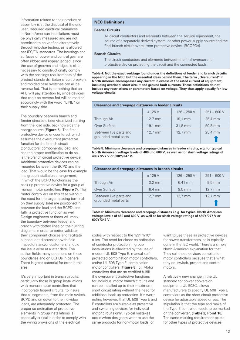
13
information related to their product or assembly is at the disposal of the end-user. Required electrical clearances in North American installations must be physically measured and are not permitted to be verified alternatively through impulse testing, as is allowed per IEC/EN standards. The housings and surfaces of power and control gear are often ribbed and appear jagged, since the use of grooves and ridges is often necessary to constructionally comply with the spacings requirements of the product standards. Eaton circuit breakers and molded case switches can all be reverse fed. That is something that an AHJ will pay attention to, since devices that can’t be reverse fed will be marked accordingly with the word “LINE” on their supply side.
The boundary between branch and feeder circuits is best visualized starting from the load side, back towards the energy source (Figure 5). The first protective device encountered, which assumes the overcurrent protective function for the branch circuit (conductors, components, load) and has the proper certification to do so, is the branch circuit protective device. Additional protective devices can be mounted between the BCPD and the load. That would be the case for example in a group installation arrangement, in which the BCPD functions as the back-up protective device for a group of manual motor controllers (Figure 7). The motor controllers (in this case without the need for the larger spacing terminal on their supply side) are positioned in between the load and the BCPD, and fulfill a protective function as well. Design engineers at times will mark the boundary between feeder and branch with dotted lines on their wiring diagrams in order to better validate their component choices and facilitate subsequent discussions with field inspectors and/or customers, should the issue arise at a later date. The author fields many questions on these boundaries and on BCPDs in general. There is great potential for error in this area.
It’s very important in branch circuits, particularly those in group installations with manual motor controllers that incorporate tapped circuits, to insure that all segments, from the main switch, BCPD and on down to the individual loads, are adequately protected. The proper co-ordination of protective elements in group installations is especially critical in order to comply with the wiring provisions of the electrical
codes with respect to the 1/3rd 1/10th rules. The need for closer co-ordination of conductor protection in group installations is alleviated by the use of modern UL 508 Type E, manual self-protected combination motor controllers, and/or UL 508 Type F, combination motor controllers (Figure 8) [5]. Motor controllers that are so certified fulfill the overcurrent protective functions for individual motor branch circuits and can be installed up to their maximum short circuit rating without the need for additional back-up protection. It’s worth noting however, that UL 508 Type E and F controllers are suitable as protective and switching devices for individual motor circuits only. Typical mistakes occur when designers want to use the same products for non-motor loads, or
want to use these as protective devices for power transformers, as is typically done in the IEC world. There’s a simple North American explanation for that. They call these devices combination motor controllers because that’s what they do: switch, protect and control motors.
A relatively new change in the UL standard for power conversion equipment, UL 508C, allows manufacturers to specify UL 508 Type E controllers as the short circuit protective device for adjustable speed drives. The stipulation is that the type and make of the Type E controller needs to be marked on the converter. (Table 2, Point 10). The same marking requirement exists for other types of protective devices
NEC Definitions
Feeder Circuits
All circuit conductors and elements between the service equipment, the source of a separately derived system, or other power supply source and the final branch-circuit overcurrent protective device. (BCOPDs).
Branch Circuits
The circuit conductors and elements between the final overcurrent protective device protecting the circuit and the connected loads.
Table 4: Not the exact verbiage found under the definitions of feeder and branch circuits
appearing in the NEC, but the essential ideas behind them. The term „Overcurrent“ in
North America encompasses any current in excess of the rated current of equipment,
including overload, short circuit and ground fault currents. These definitions do not
include any restrictions or parameters based on voltage. They thus apply equally for low
voltage circuits.
Clearance and creepage distances in feeder circuits
≤ 125 V 126 – 250 V 251 – 600 V
Through Air 12,7 mm 19,1 mm 25,4 mm
Over Surface 19,1 mm 31,8 mm 50,8 mm
Between live parts and grounded metal parts
12,7 mm 12,7 mm 25,4 mm
➡
Table 5: Minimum clearance and creepage distances in feeder circuits, e.g. for typical
North American voltage levels of 480 und 600 V, as well as for slash voltage ratings of
480Y/277 V or 600Y/347 V.
Clearance and creepage distances in branch circuits
≤ 125 V 126 – 250 V 251 – 600 V
Through Air 3,2 mm 6,41 mm 9,5 mm
Over Surface 6,4 mm 9,5 mm 12,7 mm
Between live parts and grounded metal parts
12,7 mm 12,7 mm 12,7 mm
➡Table 6: Minimum clearance and creepage distances i e.g. for typical North American
voltage levels of 480 und 600 V, as well as for slash voltage ratings of 480Y/277 V or
600Y/347 V.
WP027007EN.indd 13WP027007EN.indd 13 30.03.15 15:3630.03.15 15:36

14
that manufacturers may use for the short circuit test, such as semiconductor fuses and instantaneous-trip circuit breakers. It is, however, not necessary for either inverse time circuit breaker or standard fuse markings to appear on drives, assuming that they pass the short circuit test with both, at the full ratings required by the standard. Otherwise the drives would need to be marked with the current rating of the inverse time breaker and/or the class and ampere rating of the fuse used for the test. These markings are necessary to meet the intent of the electrical codes.
A general statement can be made that industrial control devices certified to UL 508/CSA C22.2 No. 14-05 (smaller electrical clearances), like contactors for example, are not allowed in feeder circuits (Table 2, Point 2). This also applies to Supplementary Protectors per UL 1077/ CSA C22.2 No. 235-04 (R2009). The technical committee panel for the UL 508A standard is discussing at this time under which conditions
UL 508 Type F Combination Motor Controller
Disconnect,
Short circuit,
controller and
motor overload
protection in
one combination.
= minimal coordinationrequirements
UL 508 Type F combination motor
controllers can be used up to their
maximum SCCR without back-up
protection.
Group Protection / Group Installation
BCPD
1 Branch Circuit
Feeder Circuit
1 Branch Circuit
Feeder Circuit
BCPD
BCPD A grouping of controllers has 1 only
Figure 7: Branch Circuit Protective Devices in the above diagram are installed ahead a
group of PKE-… or PKZM0-.., motor starters and DILM magnetic contactors. The BCPD
and motor starter components on the right side of the figure are mounted on a busbar
system. The manual motor controllers require the branch circuit overcurrent protective
device because their capabilities based on their certification include the motor switching
and overload protective function only [4]. The type of power distribution network in this
case has no impact with respect to the controller ratings. Yellow background = Feeder
circuit, green background = Branch Circuit.
Figure 8: UL 508 Type F combination motor controllers allow for a much simpler layout with minimal sizing requirements. The need
to co-ordinate reduced cross-sections as in group arrangements is eliminated. The short circuit and overload protective functions are
accomplished by the same device. Component co-ordination requirements are much less demanding.
M M M
(BCPD)
PKZM
The protective device
assumes the disconnect
and overcurrent protection
for the group of control-
lers and conductors.
= BCPD for the group
= Circuit Breaker or Fuse only 1 Branch Circuit, since
only 1 BCPD present
The PKZM will also tripunder short circuit conditions!
Differently sized conductors!Motor inrush currents!Co-ordination requirements!
The PKZM0 assumes the overload protection
for the motor and
conductor
Protective device
for the group
WP027007EN.indd 14WP027007EN.indd 14 30.03.15 15:3630.03.15 15:36

15
industrial components, contactors in particular, could be used in the feeder circuit, since these devices are finding more and more usage in functional safety circuits. As power switches they are also deemed to be well suited for safe and reliable isolation of energy sources under potentially hazardous conditions.
Branch Circuit Protective Devices
The application and significance of BCPD’s have been touched upon in the preceding sections. Branch Circuit Protective Devices provide overcurrent protection for all circuits from their nominal current rating up to their interrupting rating, which is to say their
short circuit current rating (SCCR). As a clarification to Table 2, Point 2 it’s worth noting that only listed inverse time circuit breakers certified to UL 489 and standard fuses certified to UL 248 are universally applicable as BCPD’s for all loads (Figure 9 and 10) (Table 7) and marked with short circuit interrupting ratings. This sets them apart from specialty components which, if they are to be used as short circuit protective devices for certain types of loads and controllers, such as drives for example, need to be identified by type and make on the equipment (Table 2, Point 10). The use of UL 508 Type E controllers in this regard is subject to the limitations highlighted in the accompanying text
to the illustration (Table 1, Point 3, -Application restrictions-) (Figure 10). Common mistakes involve the use of Type E controllers as protective devices for power transformers or heating loads (Table 2, Error 11). Both these loads can be protected by circuit breakers and fuses exclusively. Type E and Type F controllers are still relatively new to the North American landscape. They have mostly found their way into the market via imported machinery. However, their appeal is growing fast amongst North American end-users and OEMs who recognize their performance, as well as their space saving features, and are eager to take advantage of the new technology. North American standards
Suitability of various protective devices as Branch Circuit Protective Devices (BCPD)
For the following equipment/load types Type of BCPD
General Equipment protection. assemblies, conductor protection
DrivesPower con-version equipment
Motors Trans-formers
Lighting loads
Heating loads
x x (x)plus contac-tor and over-
load relay
x x x Molded case circuit breakers(Inverse Time Circuit Breakers)per UL 489, CSA C22.2 No. 5-09
x x xmostly with additional contactor
x x x Motor protective circuit breakersper UL 489, CSA C22.2 No. 5-09with additional calibration per UL 508, CSA C22.2 No. 14-05
***) ***) ***) ***) ***) ***) Supplementary Protectorsper UL 1077, CSA C22.2 No. 235-04
x x (x)plus contac-tor and over-
load relay
x x x Fusesper UL 248, CSA C22.2 No. 248
***) ***) ***) ***) ***) ***) Manual motor controllers
– (x)*) xStarter =
BCPD
– – – UL 508 Type E Self-Protected Combination Motor Controllers
– – xStarter =
BCPD
– – – UL 508 Type F Combination Motor Controllers
– – (x)**) – – – Manual motor controllerswith individual back-up protective device
– – (x)**) – – – Manual motor controllersin Group installations
(x) Conditional Usage*) The drives are tested and marked with the model number and manufacturer of the Type E controller.**) The protective device (circuit breaker or fuse) is the BCPD and the manual motor controller provides the motor overload protection.***) Not suitable as a BCPD under any circumstances!
Table 7: Inverse time circuit breakers and fuses can be universally applied as BCPDs. IEC-Manual motor controllers can be additionally evaluated
and certified to fulfill the BCPD function in individual motor circuits. A Type E controller cannot be combined with any motor controller, but
must be tested with specific controllers and marked accordingly as a Type F combination motor controller. The use of fuses may require the
specification of the class of fuse used. The interrupting rating of a BCPD, or the short circuit current rating of a combination motor controller, must
be sufficiently high enough for the application. It would have to be as high as the interrupting rating of the feeder current limiting protective device
in a 508A control panel, if the interrupting rating of the feeder device is to be used as the panel’s overall SCCR value, since the lower let-through
values of current limiting protective devices have no influence on downstream ratings of protective devices in 508A assemblies at this time.
WP027007EN.indd 15WP027007EN.indd 15 30.03.15 15:3630.03.15 15:36

16
organizations are thus faced with ever increasing pressure to incorporate many of the IEC based component designs and philosophies into the electrical codes. One can remain hopeful that the allowance of these specialty controllers as protective devices for motor loads is the first step towards expanding their functionality more in line with current
practices in the IEC world. An ongoing problem for new technology is that it takes time for it to make its way into the product and installation standards, and especially the electrical codes, which is the ultimate step towards legitimizing its application. Certification agencies must always determine that a product does not violate the requirements of the
NEC or CEC before they can certify it for usage. Ideally, new technology would also be described in electrical assembly standards like UL 508A and NFPA 79 for applications such as industrial machinery. It’s a complex and time consuming endeavor, especially considering that the cycle period for changes in the electrical codes runs typically in 3 year intervals. The picture is further complicated by conflicting interests on the part of manufacturers and trade groups who do not always pursue the same agenda when promoting changes to the codes.
The use of fuses as BCPDs is more prevalent in North America than in the IEC world, where people tend to prefer fuseless based panel engineering designs. The use of North American fuses in an IEC design based panel runs counter to the stated goal of having a layout for machinery that is truly global and uniform. IEC fuses are not acceptable in North America as protective devices and the amount of space they take up in a panel generally tends to be smaller, which would make a change to larger North American bases more problematic. Table 8 provides an overview of available fuses on the North American market. When selecting fuses as protective devices for components it’s important to consider, if applicable, the class and rating of fuse that was used to certify the equipment to make sure the correct choice of fuse can be made. Testing could involve the use of ratings and class designations which would need
///
Circuit breakers, always large spacingsFuses, always large spacingsUL 508 Type E, large spacings on
supply side only, for individual motors or drives only.
M? ?
? = All load types: e.g.HeatersTransformersLightingDrivesCapacitors
Figure 9: The type of load needs to be considered when applying UL 489/CSA C22.2
No. 5-09 circuit breakers, UL 248/CSA C22.2 No. 248 fuses and UL 508 Type E und Type
F controllers as protective devices. Circuit breakers and fuses can be universally applied,
but may require additional components in motor circuits. Type E controllers can only be
used to protect motors and drives in individual motor branch circuits.
Circuit breakers can be universally applied as branch circuit protective devices for various loads.
UL 508 Type E und F controllers provide the branch circuit protective function for individual motor branch circuits only.
FAZ…-NA PKZM4…-CB NZM…-NA UL 508 Type E *) UL 508 Type F *)
Nearly always suitable as BCPDs Limitations as BCPDs
Figure 10: It’s important to differentiate between branch circuit protective devices that are universally applicable, and those which can
fulfill the branch circuit protective function only in specific applications, e.g. for motors only. Component short circuit testing and certi-
fication markings ultimately determine the type of branch circuit protective device which can be used, e.g. not all types of devices are
suitable for drives, and some protective devices would require additional markings on components. *) In Canada, use of the large spacing BK../3-PKZ..-E terminal for Type E controllers is not required. Type E controllers at this time must all be equipped with
padlockable knobs, whether open or enclosed, in both the USA and Canada.
WP027007EN.indd 16WP027007EN.indd 16 30.03.15 15:3630.03.15 15:36

17
to be indicated on the component in the form of a marking and which would need to be relied upon for replacement purposes. The personnel safety provisions of the NFPA 70E standard with respect to fuse replacements need to be followed closely in this regard. As mentioned, the product standard requires several markings when using fuses to denote the class and type and fuse suitable for replacement purposes, if applicable. These markings normally appear in the form of labels adjacent to the fuse bases.
UL 508 Type E self-protected combination motor controllers and Type F combination motor controllers are typically rated for use in solidly grounded distribution networks only (the voltage rating needs to be particularly considered in this regard). The application of these devices in ungrounded systems, or in many delta configured networks, would most likely require an additional and suitably rated back-up protective device such as a breaker or fuse. The back-up protective device would provide the function of overcurrent protection and isolation for the branch circuit, and the controllers would assume motor overload and
switching duties. The Eaton controllers have been additionally evaluated for group installations, which would enable an arrangement of multiple controllers under one back-up branch circuit protective device, subject to the wiring and co-ordination requirements of the electrical codes for such installations [5] (i.e. protection for tapped circuits (e.g. 1/3rd rule), consideration of the starting conditions for the motors involved, summation of full load currents and applicable correction factors, ideally an arrangement that involves motors of relatively similar sizes, etc…).
The PKZM… and PKE manual motor controllers have additionally been evaluated as Tap Conductor Protectors. A certification as tap conductor protector allows the controllers to be used per the 1/10th rule provisions of the NEC under group installations. It is also worth noting that tap conductor protectors (Table 9) are mostly applicable in solidly grounded systems only. The use of Type F combination motor controllers for individual motor branch circuits can also be a very useful option to consider for these applications since, like Type E controllers, they don’t require additional back-up protection and are not subject
to the more restrictive provisions of the group installation rules.
Appropriate power distribution
networks and nominal voltage ratings
As mentioned in Table 1, Point 3, -Limitations-, as well as Point 3 of Table 2, improper equipment selection with respect to the power distribution network configuration is a very common error on the part of exporters. Many of the more compactly designed protective devices from the IEC world are rated in North America for applications in solidly grounded distribution systems only [6] (Table 10). In Germany this is the most common form of power distribution network. Solidly grounded distribution systems in North America are identified with a “slash voltage” rating. Examples of the way these systems are referenced in standards and technical documentation would be 480Y/277VAC or 600Y/347VAC. The presence of a single protective device so rated in a control panel would require the voltage rating appearing on the panel’s nameplate to reflect that system accordingly. As per Figure 12, protective devices with this rating are tested by a NRTL under configurations C and E at
Table 8: Standard North American feeder and branch circuit fuses certified per UL 248-.. and CSA C22.2 No. 248-.. including class
designations, ratings and areas of application.
WP027007EN.indd 17WP027007EN.indd 17 30.03.15 15:3630.03.15 15:36

18
the reduced voltage level between phase and ground. The set-up is used to verify that no dangerous arc-overs occur during various portions of certification testing. Any such arc-over causing the connected fuse to blow would constitute a test failure. It is possible for devices to have full, phase-to-phase/phase-to-ground ratings at lower voltages, e.g. 480V, and still be slash rated, e.g. 600Y/347VAC at higher voltage ratings. In that case, the device would be suitable in solidly grounded systems only at that higher voltage. The voltage markings on the device would then be referred to as 480 VAC and 600Y/347VAC . Please note that a slash rating alone of 600Y/347VAC does not adequately cover applications in full 480V systems. Only a fully 600V rated protective device would be able to be cover applications in straight, or full, 480V systems [6].
This can be a difficult situation for exporters of mass produced machinery who have no way of knowing ahead of time which type of power distribution network will be present at the final end-use location of their equipment. There are then 2 possible scenarios to contemplate as solutions. One would be to forego as a rule the selection of any equipment that is dependent on a solidly grounded power distribution network. The drawback would be that it would entail the likely use of larger and more numerous (additional back-up protective devices) components, and thus a more expensive machine. Another consequence of this option, which can be rather disappointing, is that the final layout would be in even greater contrast to comparable IEC based designs, and would make it harder to pursue the oft stated goal of achieving a more universal design for the machinery. The other option is one that lends itself well for
machinery with relatively smaller power requirements and involves the use of an additional power transformer whose secondary can be configured to form a solidly grounded voltage network to accommodate the equipment. In other words, create your own solidly grounded energy distribution system. Design layouts for larger machinery, which usually feature individual power transformers, can be made to insure that the secondary of the transformer is configured with a solidly grounded connection. Machinery that is exported to Canada, as a rule, is often equipped with step down transformers in order to get around the requirements of a full 600V rating for the equipment. The machinery is then operated with 400V or 480V, simply because there is a lack of fully rated 600V gear, or the 600V equipment may not be sufficiently rated to handle the breaking capacity requirements. It’s a good way to solve two problems
Table 9: The advantages and limitations of various IEC based manual motor controllers with respect to their scope of application.
Advantages and drawbacks of various motor starter configurations achieved with IEC/
EN manual motor controllers, in applications per North American electrical standards
1 Motor circuit conductors are always sized at motor full load currents (per tables) x 1.25.
2 BCPD = Branch Circuit Protective Device
Individual motor branch circuits with branch circuit
protective device
Grouping of manual motor controllers listed for group
installations
Grouping of manual motor controllers
additionally listed as tap conductor protectors
Individual motor branch circuits with
UL 508 Type E- und Type F-motor starters
Protective device required Protective device required Protective device requiredFulfills the role of the BCPD 3 branch circuit
protective device
Advantage:Application in grounded and
ungrounded networks
Advantage:Application in grounded and
ungrounded networks
Drawback:Application in solidly
grounded networks only
Drawback:Application in solidly
grounded networks only
Drawback:protentially many protective
devices repuired
Advantage:lesser amount of protective
devices repuired
Advantage:lesser amount of protective
devices repuired
Advantage:No protective device
required 1
Advantage:Conductor sizing 1
per individual motor rules
Drawback:Conductor sizing 1 and
protection per the 1/3 rule
Advantage:Conductor sizing 1 and
protection per the 1/10 rule and BCPD 2
Advantage:Conductor sizing1 per individual motor rules
Advantage:no complex group installation
provisions to follw
Drawback:group buildingmore difficult
Advantage:group buildingless difficult
Advantage:no complex group
installation provisions to follow
Drawback:additional groupings
necessary
Advantage:likely to lessen the number
of groupings necessary
WP027007EN.indd 18WP027007EN.indd 18 30.03.15 15:3630.03.15 15:36
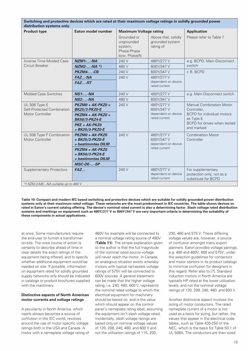
19
at once. Some manufacturers require the end-user to furnish a transformer on-site. The wise course of action is certainly to describe ahead of time in clear details the exact ratings of the equipment being offered, and to specify whether additional equipment would be needed on site. If possible, information on equipment rated for solidly grounded supply networks only should be indicated in catalogs or product brochures supplied with the machinery.
Distinctive aspects of North American
motor currents and voltage ratings
A peculiarity in North America, which nearly always becomes a source of confusion in the IEC world, revolves around the use of motor specific voltage ratings both in the USA and Canada. A motor with a nameplate voltage rating of
460V for example will be connected to a nominal voltage rating source of 480V (Table 11). The simple explanation given to the author is that the full magnitude of the nominal rated source voltage will never reach the motor. In Canada, an analogous situation exists whereby motors with typical nameplate voltage ratings of 575V will be connected to 600V sources. A general statement can be made that the higher voltage rating, i.e. 240, 480, 600 V, represents the nominal rated voltage to which the electrical equipment for machinery should be based on, and is the value which should appear on the control panel’s nameplate rating label, assuming the equipment isn’t slash voltage rated. Incidentally, slash voltage ratings are based only on nominal voltage values of 120, 208, 240, 480, and 600 V and not the utilization ratings of 115, 200,
230, 460 and 575 V. These differing voltage values are, however, a source of confusion amongst many export planners. Eaton provides voltage pairings, e.g. 480 and 460V, 600 and 575V, under the selection guidelines for contactors and motor starters in its product catalogs to minimize confusion for designers in this regard. Refer also to [7]. Standard induction motors in North America are typically HP rated at the lower utilization levels, and not the nominal voltage ratings of 120, 208, 240, 480, and 600 V.
Another distinctive aspect involves the sizing of motor conductors. The rated nameplate current of a motor is not used as a basis for sizing, but rather, the values that appear in the electrical code tables, such as Table 430-250 of the NEC, which is the basis for Table 50.1 of UL 508A. The conductors are then sized
Switching and protective devices which are rated at their maximum voltage ratings in solidly grounded power
distribution systems only.
Product type Eaton model number Maximum Voltage rating Application
Grounded or ungrounded system, Phase-Phase bzw. Phase/N
Above that, solidly grounded system rating of
Please refer to Table 7
Inverse Time Molded Case Circuit Breaker
NZM1-…-NA 240 V 480Y/277 V e.g. BCPD, Main Disconnect switchNZM2-…-NA *) 480 V 600Y/347 V
PKZM4-…-CB 240 V 600Y/347 V z. B. BCPDFAZ...-NA 240 V 480Y/277 V
dependent on device rated current
FAZ…-RT
Molded Case Switches NS1-…-NA 240 V 480Y/277 V e.g. Main Disconnect switchNS2-…-NA 480 V 600Y/347 V
UL 508 Type ESelf-Protected Combination Motor Controller
PKZM0 + AK-PKZ0 +
BK25/3-PKZ0-E
240 V 480Y/277 V 600Y/347 Vdependent on device rated current
Manual Combination Motor Controller,BCPD for individual motors as Type EBCPD for drives when tested and marked
PKZM4 + AK-PKZ0 +
BK50/3-PKZ4-E
PKE + AK-PKZ0
+ BK25/3-PKZ0-E
UL 508 Type F Combination Motor Controller
PKZM0 + AK-PKZ0
+ BK25/3-PKZ0-E
+ bestimmtes DILM
240 V 480Y/277 V 600Y/347 Vdependent on device rated current
Combination Motor Controller
PKZM4 + AK-PKZ0
+ BK50/3-PKZ4-E
+ bestimmtes DILM
MSC-DE-...-SP
Supplementary Protectors FAZ… 240 V 480Y/277 Vdependent on device rated current
For supplementary protection only, not as a substitute for BCPD
*) NZM.2-ME..-NA suitable up to 480 V
Table 10: Compact and modern IEC based switching and protective devices which are suitable for solidly grounded power distribution
systems only at their maximum rated voltage. These networks are the most predominant in IEC countries. The table shows devices so
rated in Eaton‘s current catalog offering. The device’s nominal rated current is also a determining factor. Slash voltage rated distribution
systems and markings on equipment such as 480Y/277 V or 600Y/347 V are very important criteria in determining the suitability of
these components in actual applications.
WP027007EN.indd 19WP027007EN.indd 19 30.03.15 15:3630.03.15 15:36

20
at a factor of 1.25 times the table values. Additional factors may impact conductor sizing, such as cable ratings, installation, conduit sizes, ambient temperature etc… A formulaic conversion to HP should also be made whenever applying motors that are rated in kW only. Even though a non-standard HP value is likely to result, which cannot be referenced in any code table, most field inspectors would then find it acceptable to base the motor conductor sizing on the next larger size standard HP rating found in the table.
for higher fault ratings, for example as part of a combination motor starter with fuses or circuit breakers as the protective device in the combination. The components which make up these tested and certified assemblies cannot subsequently be exchanged or interchanged in the field, as is more commonly practiced in the IEC world. High fault ratings for motor starter combinations are usually established at standardized values per the product standard, such as 50, 65 and 100kA. Eaton provides basic information on fault ratings in the online catalog, e.g. motor contactors, in association with fuses and circuit breakers, as well as high fault ratings, also in association with fuses and circuit breakers. Combination motor starter tables made up fuses or circuit breakers, together with a contactor and a separately mounted overload relay are also provided. Three component motor starter combinations with circuit breakers are typical in North America. A circuit breaker is not normally calibrated to provide motor overload protection, which explains the need for the additional motor overload relay. Eaton offers an interesting alternative in this regard consisting of a fully listed inverse time circuit breaker (Motor Protective Circuit Breaker) NZM.2.-ME…-NA, additionally evaluated and certified to provide the motor overload protective function in motor branch circuits. This represents a relatively new concept in North America [8]. The breaker, together with a magnetic motor contactor, allows the construction of a two component combination motor starter more typical of IEC based designs. This variant of circuit breaker is fully listed per UL 489 as an inverse time circuit breaker, but additionally meets the motor overload calibration requirements of UL 508. Eaton can thus supply 2 component combination starter solutions with a high SCCR rating of 65kA @ 480Y/277VAC values for motor full load currents of up to 200A.
Contactors are normally short-circuit tested per the product standard with fuses and circuit breakers that can be rated up to 400% of the contactor’s full load current ratings, a value which is based on a contactor’s application primarily in motor circuits per the electrical codes. However, the need to establish ever higher SCCR values for component usage in control panels has meant that component tests are being increasingly conducted with closer matched protective devices. The newly introduced PKZM4-..-CB molded case circuit breaker from Eaton is proving to
Sizing the conductors with this in mind ahead of time will help avoid the need to exchange conductors later on in the field.
High Fault Ratings
Power circuit components that are certified per the industrial control standard [1, 3] must undergo basic short circuit testing to establish a standard fault or SCCR rating (e.g. SCCR = 5 or 10kA, depending on the component). The component can then be submitted
The most important application restrictions of IEC based
equipment certified to North American standards
Per application:
IEC-Manual motor controllers
• only with additional back-up protection
• Group installation is possible• or certification as UL 508 Type E
Combination motor controller• or certification as UL 508 Type F
Combination motor controller• Used for motor protection only
IEC-Miniature circuit breakers• Used as Supplementary
Protectors only
Combination motor starters• mostly 3 components:
Circuit breaker, contactor, overload relay
Case by case basis, per technical ratings:
• pa. reduction in voltage ratings• pa. application in solidly grounded networks only• pa. reduction in nominal rated currents• pa. reduction in conductor ampacities
Per the type of circuit, in Feeder Circuits:
• No 508 type indsutrial control components• Exception: Incoming supply parts of UL 508 Type
E und Type F combination motor controllers• No supplementary protectors• Bus bar systems with larger electrical clearan-
ces only.• Terminals with larger electrical clearances only.
pa. = partial
Figure 11: Examples of restrictions applicable to IEC based equipment in North America
relative to IEC standards and international market conventions and practices.
Full Voltages
e.g. 480 V or 600 V:
Circuits A and BPhase / Phase
Slash Voltages
e.g. 480 Y / 277 V or 600 Y / 347 V:
Circuits C and EPhase / N
Figure 12: Test circuit configurations for full voltage (Phase-Phase) and slash voltage
(Phase-Neutral) ratings. A blown fuse during testing is indicative of a failed test.
WP027007EN.indd 20WP027007EN.indd 20 30.03.15 15:3630.03.15 15:36
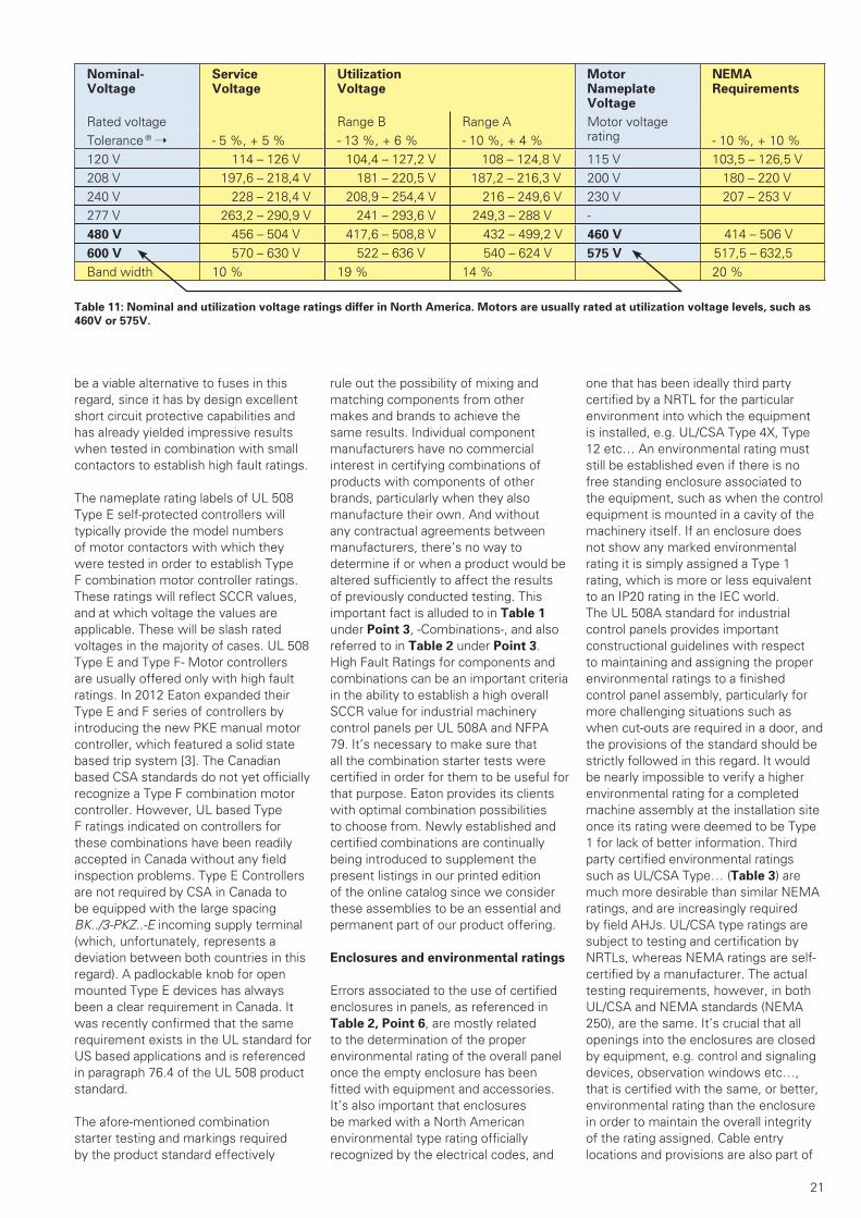
21
be a viable alternative to fuses in this regard, since it has by design excellent short circuit protective capabilities and has already yielded impressive results when tested in combination with small contactors to establish high fault ratings.
The nameplate rating labels of UL 508 Type E self-protected controllers will typically provide the model numbers of motor contactors with which they were tested in order to establish Type F combination motor controller ratings. These ratings will reflect SCCR values, and at which voltage the values are applicable. These will be slash rated voltages in the majority of cases. UL 508 Type E and Type F- Motor controllers are usually offered only with high fault ratings. In 2012 Eaton expanded their Type E and F series of controllers by introducing the new PKE manual motor controller, which featured a solid state based trip system [3]. The Canadian based CSA standards do not yet officially recognize a Type F combination motor controller. However, UL based Type F ratings indicated on controllers for these combinations have been readily accepted in Canada without any field inspection problems. Type E Controllers are not required by CSA in Canada to be equipped with the large spacing BK../3-PKZ..-E incoming supply terminal (which, unfortunately, represents a deviation between both countries in this regard). A padlockable knob for open mounted Type E devices has always been a clear requirement in Canada. It was recently confirmed that the same requirement exists in the UL standard for US based applications and is referenced in paragraph 76.4 of the UL 508 product standard.
The afore-mentioned combination starter testing and markings required by the product standard effectively
rule out the possibility of mixing and matching components from other makes and brands to achieve the same results. Individual component manufacturers have no commercial interest in certifying combinations of products with components of other brands, particularly when they also manufacture their own. And without any contractual agreements between manufacturers, there’s no way to determine if or when a product would be altered sufficiently to affect the results of previously conducted testing. This important fact is alluded to in Table 1 under Point 3, -Combinations-, and also referred to in Table 2 under Point 3. High Fault Ratings for components and combinations can be an important criteria in the ability to establish a high overall SCCR value for industrial machinery control panels per UL 508A and NFPA 79. It’s necessary to make sure that all the combination starter tests were certified in order for them to be useful for that purpose. Eaton provides its clients with optimal combination possibilities to choose from. Newly established and certified combinations are continually being introduced to supplement the present listings in our printed edition of the online catalog since we consider these assemblies to be an essential and permanent part of our product offering.
Enclosures and environmental ratings
Errors associated to the use of certified enclosures in panels, as referenced in Table 2, Point 6, are mostly related to the determination of the proper environmental rating of the overall panel once the empty enclosure has been fitted with equipment and accessories. It’s also important that enclosures be marked with a North American environmental type rating officially recognized by the electrical codes, and
one that has been ideally third party certified by a NRTL for the particular environment into which the equipment is installed, e.g. UL/CSA Type 4X, Type 12 etc… An environmental rating must still be established even if there is no free standing enclosure associated to the equipment, such as when the control equipment is mounted in a cavity of the machinery itself. If an enclosure does not show any marked environmental rating it is simply assigned a Type 1 rating, which is more or less equivalent to an IP20 rating in the IEC world. The UL 508A standard for industrial control panels provides important constructional guidelines with respect to maintaining and assigning the proper environmental ratings to a finished control panel assembly, particularly for more challenging situations such as when cut-outs are required in a door, and the provisions of the standard should be strictly followed in this regard. It would be nearly impossible to verify a higher environmental rating for a completed machine assembly at the installation site once its rating were deemed to be Type 1 for lack of better information. Third party certified environmental ratings such as UL/CSA Type… (Table 3) are much more desirable than similar NEMA ratings, and are increasingly required by field AHJs. UL/CSA type ratings are subject to testing and certification by NRTLs, whereas NEMA ratings are self-certified by a manufacturer. The actual testing requirements, however, in both UL/CSA and NEMA standards (NEMA 250), are the same. It’s crucial that all openings into the enclosures are closed by equipment, e.g. control and signaling devices, observation windows etc…, that is certified with the same, or better, environmental rating than the enclosure in order to maintain the overall integrity of the rating assigned. Cable entry locations and provisions are also part of
Table 11: Nominal and utilization voltage ratings differ in North America. Motors are usually rated at utilization voltage levels, such as
460V or 575V.
Nominal-Voltage
ServiceVoltage
UtilizationVoltage
Motor NameplateVoltage
NEMARequirements
Rated voltage Range B Range A Motor voltage ratingTolerance ® ➝ - 5 %, + 5 % - 13 %, + 6 % - 10 %, + 4 % - 10 %, + 10 %
120 V 114 – 126 V 104,4 – 127,2 V 108 – 124,8 V 115 V 103,5 – 126,5 V208 V 197,6 – 218,4 V 181 – 220,5 V 187,2 – 216,3 V 200 V 180 – 220 V240 V 228 – 218,4 V 208,9 – 254,4 V 216 – 249,6 V 230 V 207 – 253 V277 V 263,2 – 290,9 V 241 – 293,6 V 249,3 – 288 V -480 V 456 – 504 V 417,6 – 508,8 V 432 – 499,2 V 460 V 414 – 506 V600 V 570 – 630 V 522 – 636 V 540 – 624 V 575 V 517,5 – 632,5Band width 10 % 19 % 14 % 20 %
WP027007EN.indd 21WP027007EN.indd 21 30.03.15 15:3630.03.15 15:36
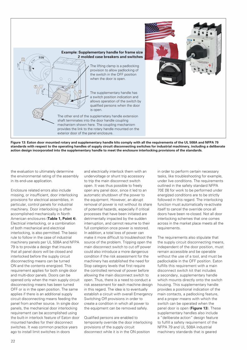
22
the evaluation to ultimately determine the environmental rating of the assembly in its end-use application.
Enclosure related errors also include missing, or insufficient, door interlocking provisions for electrical assemblies, in particular, control panels for industrial machinery. Door interlocking is often accomplished mechanically in North American enclosures (Table 1, Point 4). Electrical interlocking, or a combination of both mechanical and electrical interlocking, is also permitted. The basic rule to follow in the case of industrial machinery panels per UL 508A and NFPA 79 is to provide a design that insures that all panel doors will be closed and interlocked before the supply circuit disconnecting means can be turned ON and the contents energized. This requirement applies for both single door and multi-door panels. Doors can be opened only when the main supply circuit disconnecting means has been turned OFF or is in the open position. The same applies if there is an additional supply circuit disconnecting means feeding the panel from another source. In single door panels, the mechanical door interlocking requirement can be accomplished using the built-in interlock feature of Eaton door mounted handles for their disconnect switches. It was common practice years ago to install limit switches in doors
and electrically interlock them with an undervoltage or shunt trip accessory to trip the main disconnect switch open. It was thus possible to freely open any panel door, since it led to an automatic shutdown of the power to the equipment. However, an abrupt removal of power is not without its share of potential hazards, especially if critical processes that have been initiated are detrimentally impacted by the sudden interruption, and cannot resume to their full completion once power is restored. In addition, a total loss of power can make it more difficult to troubleshoot the source of the problem. Tripping open the main disconnect switch to cut off power could also introduce a more dangerous condition if the risk assessment for the machinery has established the need for Stop category levels that first require the controlled removal of power before allowing the main disconnect switch to open. Thus, there is a need to conduct a risk assessment for each machine design in this regard. The idea is to eventually establish a circuit with overall Emergency Switching Off provisions in order to create a condition in which all power to the equipment can be removed safely.
Qualified persons are enabled to temporarily override the door interlocking provisions of the supply circuit disconnect while it is in the ON position
in order to perform certain necessary tasks, like troubleshooting for example, under live conditions. The requirements outlined in the safety standard NFPA 70E [9] for work to be performed under energized conditions are to be strictly followed in this regard. The interlocking function must automatically re-activate itself to cancel the override once all doors have been re-closed. Not all door interlocking schemes that one comes across in the market place meets all the requirements.
The requirements also stipulate that the supply circuit disconnecting means, independent of the door position, must remain accessible and be operable without the use of a tool, and must be padlockable in the OFF position. Eaton fulfills this requirement with a main disconnect switch kit that includes a secondary, supplementary handle which mounts directly onto the switch housing. This supplementary handle provides a positional indication of the main contacts, a padlocking feature, and a proper means with which the switch can be operated when the panel door is open (Figure 13). These supplementary handles also include a “deliberate action” design feature to fulfill a safety requirement of the NFPA 79 and UL 508A industrial machinery standards that is geared
Figure 13: Eaton door mounted rotary and supplementary handle kits comply with all the requirements of the UL 508A and NFPA 79
standards with respect to the operating handles of supply circuit disconnecting switches for industrial machinery, including a deliberate
action design incorporated into the supplementary handle to meet the enclosure interlocking provisions of the standards.
TRIP
ON
3
1 2
Q20
°
TRIP
OFF
ON
Q20
°
1
The lifting clamp is a padlockingprovision to allow padlocking of the switch in the OFF position when the door is open.
The other end of the supplemetary handle extension shaft terminates into the door handle coupling mechanism shown here. The coupling mechanism provides the link to the rotary handle mounted on the exterior door of the panel enclosure.
The supplementary handle has a switch position indication and allows operation of the switch by qualified persons when the door is open.
Example: Supplementary handle for frame size
2 molded case breakers and switches
WP027007EN.indd 22WP027007EN.indd 22 30.03.15 15:3630.03.15 15:36

23
towards preventing inadvertent closing of the disconnecting means while the enclosure door is open. In order to engage the switch mechanism the handle must first be turned towards the ON position about 15 to 20°, depending on the frame size, and then be deliberately pushed down and turned simultaneously in order to complete the operation [10]. The inspectors are increasingly monitoring this situation very closely to insure that the deliberate action requirement of the standard is met. They are also actively asking for the exchange and replacement of main disconnect switches which they deem inadequate in fulfilling the requirement. The deliberate action requirement, as spelled out in the standards, deals more specifically with enclosure interlocking requirements, but it also directly impacts all door mounted rotary handle operators of IEC based disconnect switches which separate from the switch body when the enclosure door is open! Thus the need for the elaborate design features of the Eaton NFPA 79 supply circuit disconnecting switch operator kit.
There are applications, usually involving very large machines, in which the power supply source is furnished directly by the end-user, sometimes in specially enclosed electrical rooms that are not accessible to non-qualified personnel. The machinery manufacturer in this case is often asked to supply the machinery control portion, housed in an industrial control panel, but without its own supply circuit disconnecting means. The machinery control portion will also usually involve the supply of „intelligent“ loads equipped with adjustable speed drives and/or servos, as well as the necessary software to run them. There is always a greater need in these applications to insure that communication channels between the supplier of the highly automated machinery and the end-user, as well as with the AHJ, are well established. It’s also recommended to supply enclosures that allow access only to qualified persons. That can be easily achieved with the provision of customized safety locks with special keys for personnel to use when accessing the enclosure, rather than standardized enclosure locking systems that allow entry with commonly available keys or tools. Another worthwhile consideration may be to provide functionally safe circuitry in the control portion which would allow electrical actuation of the main disconnecting means from within the panel (in association with Lock Out/
Tag Out provisions and markings per NFPA 70E requirements). Certain machines may have cavities external to the control panel which are used to house additional electrical components. It’s likely that the need to access these machinery mounted components will be rare, so it’s recommended to close off the door or opening of this cavity with screws, so that its cover doesn’t have to be interlocked or require any special monitoring. A warning symbol should also be affixed to the cover if it’s not readily apparent from the outside that electrical components are mounted inside.
There is an additional aspect which is sometimes overlooked in enclosures. Individually enclosed components and combinations need to be tested in their respective enclosures. Enclosure volumes, which are established through product testing, represent minimum values which an installer or panel builder must abide by when planning a layout for an industrial control panel. Larger enclosures are also better at absorbing internal pressures released from short circuits inside the panel, and are able to more effectively dissipate temperature rises from energized components. The enclosure volumes established through short-circuit and temperature rise testing of combination motor starters, whether individually enclosed or in MCC (Motor Control Center) units, must thus be followed and considered as absolute minimum values. Individually enclosed components and combinations are not always available from European based manufacturers as complete type tested assemblies. The main reason is often tied to low demand for those specific types, and the desire of customers to have more flexibility in determining how best to utilize available enclosure types and sizes to house components. Another common mistake is to improperly size conductor cross-sections for the application and end up with smaller wire than what the components were tested with per the requirements of the product standard. Conductors do more than just conduct the electric current; they also draw heat away from the electrical components to which they are connected. Enclosure layouts should also leave ample room to make sure that requirements for minimum cable bending radii are followed. Tables are provided in the electrical codes (NEC/CEC) to this effect, and it is an aspect that is always closely monitored by the approval authorities. Market conventions differ somewhat in this respect. In North America, generally speaking, field wiring
will be terminated more often directly onto the power component whereas in IEC based assemblies, the use of terminal blocks for both power and control connections is more prevalent. North American layouts will, therefore, generally require more free space to accommodate this practice.
Grounding issues
Proper grounding concerns (Table 2,
Point 12) are very rarely an issue for European based industrial machinery and its associated electrical control equipment. Grounding related issues also occupy the last spot in the table statistically for errors encountered in North American assemblies. Although machinery manufacturers and panel builders supply their equipment usually completely assembled and wired, it’s still difficult to determine whether grounding related problems develop because the equipment is somehow lacking in this regard, or if there are grounding incompatibility issues with the supply source at the installation site. In any case, the grounding requirements of US based installations is thoroughly covered by NEC Article 250 and must be followed. These requirements are fully compatible with those that are outlined in sections 15, 16 and 17 of the UL 508A standard and in Chapter 8 of NFPA 79 for industrial control panels and the electrical equipment associated to industrial machinery.
The use of conduits (primarily rigid but also flexible metal conduits, as well as non-metallic conduit, also rigid and flexible in design) is the most popular and accepted means in North America of enclosing and protecting conductors that are used to distribute the electrical energy throughout a plant or industrial manufacturing location. Individual conductors, more so than multi-conductor jacketed assemblies, are pulled through these conduits to their final termination point. The NEC allows the use of rigid and flexible metal conduit as the equipment grounding conductor under certain defined conditions. However, the use of separately run equipment grounding conductors is a more frequently utilized method in modern installations. The conduits must establish and/or maintain continuity of ground throughout the installation and with the enclosures onto which they are terminated (Table 1, Point 4). The use of non-metallic enclosures in certain situations makes it especially imperative that proper ground continuity, ideally through the presence of a separate
WP027007EN.indd 23WP027007EN.indd 23 30.03.15 15:3630.03.15 15:36
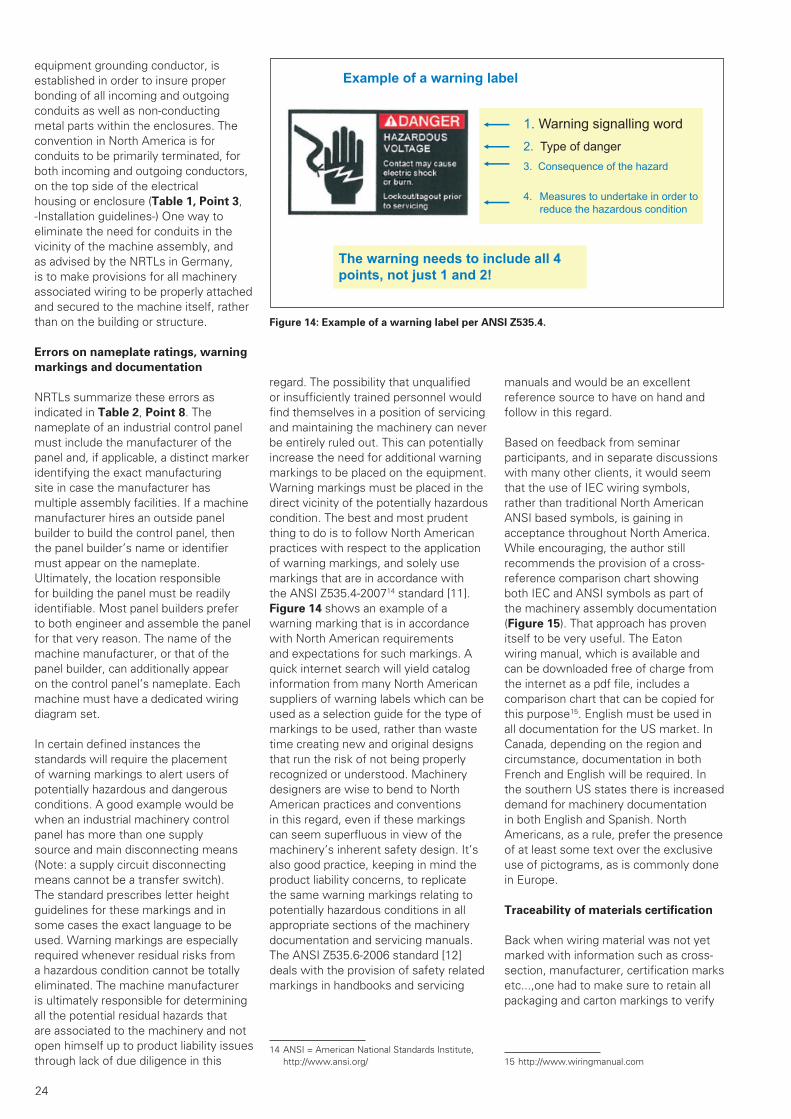
24
equipment grounding conductor, is established in order to insure proper bonding of all incoming and outgoing conduits as well as non-conducting metal parts within the enclosures. The convention in North America is for conduits to be primarily terminated, for both incoming and outgoing conductors, on the top side of the electrical housing or enclosure (Table 1, Point 3, -Installation guidelines-) One way to eliminate the need for conduits in the vicinity of the machine assembly, and as advised by the NRTLs in Germany, is to make provisions for all machinery associated wiring to be properly attached and secured to the machine itself, rather than on the building or structure.
Errors on nameplate ratings, warning
markings and documentation
NRTLs summarize these errors as indicated in Table 2, Point 8. The nameplate of an industrial control panel must include the manufacturer of the panel and, if applicable, a distinct marker identifying the exact manufacturing site in case the manufacturer has multiple assembly facilities. If a machine manufacturer hires an outside panel builder to build the control panel, then the panel builder’s name or identifier must appear on the nameplate. Ultimately, the location responsible for building the panel must be readily identifiable. Most panel builders prefer to both engineer and assemble the panel for that very reason. The name of the machine manufacturer, or that of the panel builder, can additionally appear on the control panel’s nameplate. Each machine must have a dedicated wiring diagram set.
In certain defined instances the standards will require the placement of warning markings to alert users of potentially hazardous and dangerous conditions. A good example would be when an industrial machinery control panel has more than one supply source and main disconnecting means (Note: a supply circuit disconnecting means cannot be a transfer switch). The standard prescribes letter height guidelines for these markings and in some cases the exact language to be used. Warning markings are especially required whenever residual risks from a hazardous condition cannot be totally eliminated. The machine manufacturer is ultimately responsible for determining all the potential residual hazards that are associated to the machinery and not open himself up to product liability issues through lack of due diligence in this
regard. The possibility that unqualified or insufficiently trained personnel would find themselves in a position of servicing and maintaining the machinery can never be entirely ruled out. This can potentially increase the need for additional warning markings to be placed on the equipment. Warning markings must be placed in the direct vicinity of the potentially hazardous condition. The best and most prudent thing to do is to follow North American practices with respect to the application of warning markings, and solely use markings that are in accordance with the ANSI Z535.4-200714 standard [11]. Figure 14 shows an example of a warning marking that is in accordance with North American requirements and expectations for such markings. A quick internet search will yield catalog information from many North American suppliers of warning labels which can be used as a selection guide for the type of markings to be used, rather than waste time creating new and original designs that run the risk of not being properly recognized or understood. Machinery designers are wise to bend to North American practices and conventions in this regard, even if these markings can seem superfluous in view of the machinery’s inherent safety design. It’s also good practice, keeping in mind the product liability concerns, to replicate the same warning markings relating to potentially hazardous conditions in all appropriate sections of the machinery documentation and servicing manuals. The ANSI Z535.6-2006 standard [12] deals with the provision of safety related markings in handbooks and servicing
14 ANSI = American National Standards Institute, http://www.ansi.org/
manuals and would be an excellent reference source to have on hand and follow in this regard.
Based on feedback from seminar participants, and in separate discussions with many other clients, it would seem that the use of IEC wiring symbols, rather than traditional North American ANSI based symbols, is gaining in acceptance throughout North America. While encouraging, the author still recommends the provision of a cross-reference comparison chart showing both IEC and ANSI symbols as part of the machinery assembly documentation (Figure 15). That approach has proven itself to be very useful. The Eaton wiring manual, which is available and can be downloaded free of charge from the internet as a pdf file, includes a comparison chart that can be copied for this purpose15. English must be used in all documentation for the US market. In Canada, depending on the region and circumstance, documentation in both French and English will be required. In the southern US states there is increased demand for machinery documentation in both English and Spanish. North Americans, as a rule, prefer the presence of at least some text over the exclusive use of pictograms, as is commonly done in Europe.
Traceability of materials certification
Back when wiring material was not yet marked with information such as cross-section, manufacturer, certification marks etc...,one had to make sure to retain all packaging and carton markings to verify
15 http://www.wiringmanual.com
1. Warning signalling word2. Type of danger3. Consequence of the hazard
4. Measures to undertake in order to reduce the hazardous condition
Example of a warning label
The warning needs to include all 4 points, not just 1 and 2!
Figure 14: Example of a warning label per ANSI Z535.4.
WP027007EN.indd 24WP027007EN.indd 24 30.03.15 15:3630.03.15 15:36

25
the data, and thus the problems alluded to in Table 2, Point 9 had much greater significance. Today, any material which lacks thesee key markings will be subject to close scrutiny. Plastic materials are especially critical with respect to their flammability ratings. Errors can be easily made, for example, when choosing the right kind of material for observation windows in panels, or any kind of cover plates for electrical components, or when putting together panel bus bar systems from loose parts. It’s not just a matter of getting the technical features right. The proper use and application of materials in this regard must be sanctioned by the standard, and verifiable by the inspection authorities accordingly for evaluation purposes.
Short Circuit Current Rating (SCCR)
The determination of an overall short circuit current rating per Table 1,
Point 5, is now one of the key aspects to consider in the design of industrial control panels. The resultant value must be part of the data appearing on the control panel’s nameplate. The inference
Figure 15: Excerpt of a comparison between IEC and ANSI electrical symbols.
Source: Chapter 9, Eaton Wiring Manual 2011, “Automation and Power Distribution. http://www.wiringmanual.com
Figure 16: The figure on the left shows an example of back-up protection per IEC
practices. The presence of the Q1 or F2 protective device increases the overall short
circuit rating of outgoing switches Q2 through Q4 up to a desired value established and
verified through testing. Manufacturers routinely include technical data on permissible
component combinations in their product catalogs to this effect. The principle would
be referred to as “Series Ratings” in North America. The right side of the figure shows
a current limiting upstream protective device, either Q5 or F2. Per IEC practices the
sizing of protective devices Q6 through Q8 relative to their short circuit rating would
be established in accordance with the let-through values of the upstream devices.
This allows the possibility for more compact and economical components with lower
short circuit ratings to be installed downstream. Both these principles are currently
not permitted as a means to establish overall short circuit current ratings for industrial
control panels per the UL 508A standard, although the electrical codes do permit the
practice under defined conditions for other types of applications.
Export to World Markets and North AmericaElectrical circuit symbols, Europe – North America
Eaton Wiring Manual 06/11
9-30
9
Electromechanical operating device with On-delay
or or
x device code letter table, page 9-17
Electromechanical device with Off-delay
or or
x device code letter table, page 9-17
Electromechanical device with On- and Off-delay
or or
x device code letter table, page 9-17
Electromechanical device of a thermal relay or
Contacts
N/O contact or or
N/C contact or
Changeover contact with interruption
or
Early-make N/O contact of a contact assembly
TC or TDC
Late-break N/C contact of a contact assembly
T0 or TD0
Description IEC (DIN EN) NEMA ICS/ANSI/IEEE
07-15-08
×
07-15-07
×
07-15-09
×
07-15-21
07-02-01 07-02-02
07-02-03
07-02-04
07-04-01
07-04-03
Export to World Markets and North AmericaElectrical circuit symbols, Europe – North America
Eaton Wiring Manual 06/11
9-31
9
N/O contact, delayed when closing
or
N/C contact, delayed when reclosing
or
Control devices
Push-button (not stay-put)
Spring-return switches with N/C contact, manually operated by pushing, e.g. push-button
Spring-return switches with N/O and N/C contacts, manually operated by pushing
Spring-return switches with latching position and one N/O contact, manually operated by pushing
Spring-return switches with latching position and one N/C contact, manually operated by striking (e.g. mushroom button)
Position switches (N/O contacts) Limit switches (N/O contacts)
Position switches (N/C contacts)Limit switches (N/C contacts)
Spring-return switches with N/O contacts, mechanically operated, N/O contacts closed
Description IEC (DIN EN) NEMA ICS/ANSI/IEEE
07-05-02 07-05-01T.C.
07-05-03 07-05-04T.C.
07-07-02
PB
PB
PB
PB
07-08-01
LS
07-08-02
LS
LS
Back-up-Protection per IEC-Practices Application of current limitingback-up protective devices
WP027007EN.indd 25WP027007EN.indd 25 30.03.15 15:3630.03.15 15:36

26
from Table 2 is that the NRTLs, up to this point anyway, do not consider this requirement to be overly prone for errors, since it doesn’t even show up as a problem issue in the tabulation. That is perhaps due to the degree of uncertainty which still prevails this topic. There are constant efforts under way to update Supplement SB of the UL 508A in this regard, which is the predominant document used in North America to establish SCCR values for control panels. A practical goal would be, for example, at least in the case of large machinery, to establish values more in line with the true relationship which exists in the field between the current rating of the machinery and the overall short circuit rating that is to be realistically expected. If a piece of machinery is large enough to require its own power transformer then it stands to reason that the available short circuit current of that power transformer will likely be high. Thus, the SCCR associated to the machinery assembly should also be correspondingly high. The author published a more extensive paper on this topic some time ago [13]. At the time of this writing the situation is such that many machinery and panel builders are mostly assigning overall values of 10kA to their panels and assemblies. Some NRTL field inspectors purposely avoid providing specific details on the topic whereas others advise the use of a 5kA minimum SCCR value to avoid the need for closer checking. There have also been important discussions on the effect of wire ferrules on component SCCR values, and the initial plan had been to limit ferrule equipped terminations to 10kA ceilings, which would have made it very difficult to achieve an overall panel value greater than that rating. The topic has in the meantime been thoroughly discussed amongst UL and 508A committee panel members and the ruling is, rightfully, that the use of ferrules does not have any negative or limiting impact on the SCCR of a component.
The UL 508A standard is also more restrictive than the IEC when it comes to fully utilizing the benefits of current limitation technology in control panels. Specifically, there are limitations imposed when evaluating component ratings based on lower let-through values and in the use of series connected protective devices with current limiting capabilities. A series rating, i.e. one based on the ability of a protective device to raise the overall rating of a lesser rated downstream protective device (such as FAZ…-NA) when used in a series connected arrangement (Figure 16),
is not a sanctioned practice in North American industrial control panels. Thus, the short circuit rating of all protective devices in a panel must have a SCCR that is at least equal to, or greater than, the overall short circuit rating that is assigned to the panel. This conservative approach can make the application of certain product lines of protective devices much more difficult, or eliminate their usage altogether.
Machinery manufacturers and panel builders, at least in Germany, strive to do the right thing and are very much interested in fully complying with the SCCR requirements outlined in the North American standards. But there remains much uncertainty on how best to achieve this.
Let’s keep in mind too that the reliability of machinery designed to IEC standards has proven itself the world over. What is produced in the IEC world can’t be all bad. It’s also difficult to obtain informational self-help guides or assistance manuals from North America which specifically address this particular requirement of the standard. In spite of this it is strongly recommended that machinery and panel builders be clear in specifying as part of their product offer to potential clients a SCCR rating for the North American equipment they would be supplying, since it is now a firmly established requirement of the electrical codes. There are always external measures which can be implemented on site to reduce the available fault current at the incoming terminals of a control panel and satisfy requirements.
The basic principle in establishing an overall SCCR value for a control panel revolves around the need to evaluate all the components and combinations which make up the power circuit, and singling out those with the lowest SCCR values. The standard then allows the possibility of raising the ratings of lesser rated, passive power circuit components through the use of power transformers, or through the use of a current limiting protective device such as a circuit breaker or fuse in the feeder circuit which would lower overall let-through values downstream from the device. The lowest SCCR value determined from this evaluation establishes the overall short circuit rating (SCCR) of the panel. This value must then appear on the control panel nameplate to meet the requirements of both the standard and the electrical codes.
Summary:
Both the positive experiences and unfortunate mishaps of others can enlighten us in determining the most effective way to avoid costly and time consuming export related errors. The paper attempted to highlight the most commonly made mistakes and provide advice on how to avoid them. The statistics demonstrate that the fall-out from these mistakes should not be under-estimated, and that purposely avoiding North American standards is unwise since all of these errors are likely to be flagged by field inspectors and AHJs. The negative consequences of having to remedy any of these mistakes after the fact will become immediately clear to a project engineer. In extreme cases it could mean a completely re-designed panel. Proper adherence to the requirements of North American codes and standards will help you avoid these major mistakes, and greatly improve your chances of designing and building a control panel assembly that will be approved by North American AHJs. Familiarity with the standards would also increase the odds of more quickly obtaining NRTL certification for your manufacturing facility should this option become more feasible in your business plan.
The complexity involved in designing „North American“ machinery is nearly always greater than its IEC equivalent. The broader the involvement in this business, the greater the need to access proper training and support material on the subject, and to have on hand current and relevant standards to follow. The additional outlay of resources should be readily documented in order to more accurately gauge and calculate the ultimate costs from machine to machine.
Validity: December 2014
The contents of this paper reflect editions of relevant North American codes & standards valid as of this date. Binding technical information on Eaton equipment mentioned throughout the paper can be found in the most recent versions of product catalogs and documentation. The suitability of the recommendations provided in the paper should be checked against the specific requirements of each application.
WP027007EN.indd 26WP027007EN.indd 26 30.03.15 15:3630.03.15 15:36

27
Acknowledgment:
The author gratefully acknowledges the technical support of the following individual in the preparation of this paper:
Mr. Andre R. Fortin, BA Phys.
……
References:
[1] „Schaltgeräte und Schaltanlagen für den Weltmarkt und für den Export nach Nordamerika“ VKF0211-563D
„Components and Systems suitable for World Markets and Export to North America“VKF0211-563GBEaton Industries GmbH, Bonn, 2010
[2] Wolfgang Esserweitere Veröffentlichungen:www.eaton.eu/veroeffentlichungen
www.eaton.eu/publications
[3] Wolfgang Esser„Leichtere Produktauswahl für den Export nach Nordamerika“VER0211-969de
„Product selection for North American exports made easy“VER0211-969enEaton Industries GmbH, Bonn, 2010
[4] Mark W. Earley, Jeffrey S. Sargent“National Electrical Code HandbookTwelfth EditionInternational Electrical Code SeriesNational Fire Protection Association, Quincy, Massachusetts
[5] Wolfgang Esser„Besondere Bedingungen für den Einsatz von Motorschutzschaltern und Motorstartern in Nordamerika“VER1210+1280-928D
„Special considerations governing the application of Manual Motor Controllers and Motor Starters in North America“VER1210+1280-928GB, Eaton Industries GmbH, Bonn, 2010
[6] Wolfgang Esser„Exportrelevante Spannungs-angaben und Netzformen in Nordamerika“VER4300-965de
„Export relevant voltage information and mains forms in North America“VER4300-965enEaton Industries GmbH, Bonn, 2010
[7] Wolfgang Esser„Leistungsschilder richtig nutzen – erfolgreich nach Nordamerika exportieren“VER4300-962de
„Be more successful in exports to North America – With the use of properly certified and marked equipment”VER4300-962enEaton Industries GmbH, Bonn, 2010
[8] Wolfgang Esser„2-Komponenten-Motorstarter für den Einsatz in Nordamerika“VER1200+2100-967de
„2-Component Combination Motor Controller solutions for North America”VER1200+2100-967enEaton Industries GmbH, Bonn, 2010
[9] NFPA 70E, Standard for Electrical Safety in the Workplace, 2009
[10] Wolfgang Esser„Hauptschalter mit Drehgriffen konform mit NFPA 79 und UL 508A einsetzen.“VER1230-966de
„Supply circuit disconnecting means with rotary handles in compliance with NFPA 79 and UL 508A”VER1230-966enEaton Industries GmbH, Bonn, 2010
[11] ANSI Z535.4-2007, “American National Standard for Product Safety Signs and Labels”
[12] ANSI Z535.6-2006, “American National Standard For Product Safety Information In Product Manuals, Instructions, And Other Collateral Materials”
[13] Wolfgang Esser„SCCR – Overall Panel Short Circuit Current Rating – gemäß NEC und UL Standards“VER 0211-956D
„SCCR – Overall Panel Short Circuit Current Rating – per NEC and UL Standards“VER0211-959GB, Article No. 110102Moeller GmbH, Bonn, 2007
WP027007EN.indd 27WP027007EN.indd 27 30.03.15 15:3630.03.15 15:36

Find your addresses on
www.eaton.eu/contact
After Sales Service
Eaton Industries GmbHHein-Moeller-Straße 7-1153115 BonnTel. +49 (0) 228 602-3640Fax +49 (0) 228 602-61400Hotline +49 (0) 1805 223822E-Mail: [email protected]/aftersales
Eaton Industries GmbH
Hein-Moeller-Str. 7–11D-53115 BonnGermany
© 2015 by Eaton CorporationAll rights reservedPrinted in Germany 03/15Publication No.: WP027007ENip March 2015Article No.: 180528
Moeller series is a registered trademark of Eaton Corporation
All other trademarks are property of their respective owners.
SmartWire-DT® is a registered trademark of Eaton Corporation.
Eaton is dedicated to ensuring that reliable, efficient and safe power is available when it’s needed most. With unparalleled knowledge of electrical power management across industries, experts at Eaton deliver customized, integrated solutions to solve our customers’ most critical challenges.
Our focus is on delivering the right solution for the application. But, decision makers demand more than just innovative products. They turn to Eaton for an unwavering commitment to personal support that makes customer success a top priority. For more information, visit www.eaton.eu/electrical.
WP027007EN.indd 28WP027007EN.indd 28 30.03.15 15:3630.03.15 15:36